US20170040887A1 - Dc/ac converter apparatus comprising means for controlling the reactive power and power conversion and generation system comprising such dc/ac converter apparatus - Google Patents
Dc/ac converter apparatus comprising means for controlling the reactive power and power conversion and generation system comprising such dc/ac converter apparatus Download PDFInfo
- Publication number
- US20170040887A1 US20170040887A1 US15/227,544 US201615227544A US2017040887A1 US 20170040887 A1 US20170040887 A1 US 20170040887A1 US 201615227544 A US201615227544 A US 201615227544A US 2017040887 A1 US2017040887 A1 US 2017040887A1
- Authority
- US
- United States
- Prior art keywords
- power
- converter apparatus
- current
- active
- reactive
- Prior art date
- Legal status (The legal status is an assumption and is not a legal conclusion. Google has not performed a legal analysis and makes no representation as to the accuracy of the status listed.)
- Granted
Links
- 238000006243 chemical reaction Methods 0.000 title claims description 12
- 230000033228 biological regulation Effects 0.000 claims description 18
- 238000000034 method Methods 0.000 claims description 15
- 230000002457 bidirectional effect Effects 0.000 claims description 9
- 238000002347 injection Methods 0.000 claims description 9
- 239000007924 injection Substances 0.000 claims description 9
- 208000019300 CLIPPERS Diseases 0.000 claims description 7
- 208000021930 chronic lymphocytic inflammation with pontine perivascular enhancement responsive to steroids Diseases 0.000 claims description 7
- 238000010248 power generation Methods 0.000 claims description 4
- 238000005259 measurement Methods 0.000 claims description 3
- 238000012545 processing Methods 0.000 claims description 2
- 238000010586 diagram Methods 0.000 description 4
- 239000003990 capacitor Substances 0.000 description 3
- 239000000446 fuel Substances 0.000 description 3
- 230000007423 decrease Effects 0.000 description 2
- 238000012546 transfer Methods 0.000 description 2
- 238000004891 communication Methods 0.000 description 1
- 230000005611 electricity Effects 0.000 description 1
- 239000007789 gas Substances 0.000 description 1
- 239000005431 greenhouse gas Substances 0.000 description 1
- 238000009434 installation Methods 0.000 description 1
- 230000010354 integration Effects 0.000 description 1
- 238000004519 manufacturing process Methods 0.000 description 1
- 238000005457 optimization Methods 0.000 description 1
- 239000000243 solution Substances 0.000 description 1
- 238000011144 upstream manufacturing Methods 0.000 description 1
Images

Classifications
-
- H—ELECTRICITY
- H02—GENERATION; CONVERSION OR DISTRIBUTION OF ELECTRIC POWER
- H02M—APPARATUS FOR CONVERSION BETWEEN AC AND AC, BETWEEN AC AND DC, OR BETWEEN DC AND DC, AND FOR USE WITH MAINS OR SIMILAR POWER SUPPLY SYSTEMS; CONVERSION OF DC OR AC INPUT POWER INTO SURGE OUTPUT POWER; CONTROL OR REGULATION THEREOF
- H02M1/00—Details of apparatus for conversion
- H02M1/42—Circuits or arrangements for compensating for or adjusting power factor in converters or inverters
-
- H—ELECTRICITY
- H02—GENERATION; CONVERSION OR DISTRIBUTION OF ELECTRIC POWER
- H02J—CIRCUIT ARRANGEMENTS OR SYSTEMS FOR SUPPLYING OR DISTRIBUTING ELECTRIC POWER; SYSTEMS FOR STORING ELECTRIC ENERGY
- H02J3/00—Circuit arrangements for ac mains or ac distribution networks
- H02J3/18—Arrangements for adjusting, eliminating or compensating reactive power in networks
- H02J3/1821—Arrangements for adjusting, eliminating or compensating reactive power in networks using shunt compensators
- H02J3/1835—Arrangements for adjusting, eliminating or compensating reactive power in networks using shunt compensators with stepless control
- H02J3/1842—Arrangements for adjusting, eliminating or compensating reactive power in networks using shunt compensators with stepless control wherein at least one reactive element is actively controlled by a bridge converter, e.g. active filters
-
- G—PHYSICS
- G01—MEASURING; TESTING
- G01R—MEASURING ELECTRIC VARIABLES; MEASURING MAGNETIC VARIABLES
- G01R21/00—Arrangements for measuring electric power or power factor
- G01R21/001—Measuring real or reactive component; Measuring apparent energy
- G01R21/003—Measuring reactive component
-
- G—PHYSICS
- G01—MEASURING; TESTING
- G01R—MEASURING ELECTRIC VARIABLES; MEASURING MAGNETIC VARIABLES
- G01R21/00—Arrangements for measuring electric power or power factor
- G01R21/133—Arrangements for measuring electric power or power factor by using digital technique
- G01R21/1331—Measuring real or reactive component, measuring apparent energy
-
- H—ELECTRICITY
- H02—GENERATION; CONVERSION OR DISTRIBUTION OF ELECTRIC POWER
- H02J—CIRCUIT ARRANGEMENTS OR SYSTEMS FOR SUPPLYING OR DISTRIBUTING ELECTRIC POWER; SYSTEMS FOR STORING ELECTRIC ENERGY
- H02J3/00—Circuit arrangements for ac mains or ac distribution networks
- H02J3/12—Circuit arrangements for ac mains or ac distribution networks for adjusting voltage in ac networks by changing a characteristic of the network load
- H02J3/16—Circuit arrangements for ac mains or ac distribution networks for adjusting voltage in ac networks by changing a characteristic of the network load by adjustment of reactive power
-
- H02J3/383—
-
- H—ELECTRICITY
- H02—GENERATION; CONVERSION OR DISTRIBUTION OF ELECTRIC POWER
- H02J—CIRCUIT ARRANGEMENTS OR SYSTEMS FOR SUPPLYING OR DISTRIBUTING ELECTRIC POWER; SYSTEMS FOR STORING ELECTRIC ENERGY
- H02J3/00—Circuit arrangements for ac mains or ac distribution networks
- H02J3/38—Arrangements for parallely feeding a single network by two or more generators, converters or transformers
- H02J3/46—Controlling of the sharing of output between the generators, converters, or transformers
- H02J3/48—Controlling the sharing of the in-phase component
-
- H—ELECTRICITY
- H02—GENERATION; CONVERSION OR DISTRIBUTION OF ELECTRIC POWER
- H02J—CIRCUIT ARRANGEMENTS OR SYSTEMS FOR SUPPLYING OR DISTRIBUTING ELECTRIC POWER; SYSTEMS FOR STORING ELECTRIC ENERGY
- H02J3/00—Circuit arrangements for ac mains or ac distribution networks
- H02J3/38—Arrangements for parallely feeding a single network by two or more generators, converters or transformers
- H02J3/46—Controlling of the sharing of output between the generators, converters, or transformers
- H02J3/50—Controlling the sharing of the out-of-phase component
-
- H—ELECTRICITY
- H02—GENERATION; CONVERSION OR DISTRIBUTION OF ELECTRIC POWER
- H02J—CIRCUIT ARRANGEMENTS OR SYSTEMS FOR SUPPLYING OR DISTRIBUTING ELECTRIC POWER; SYSTEMS FOR STORING ELECTRIC ENERGY
- H02J7/00—Circuit arrangements for charging or depolarising batteries or for supplying loads from batteries
- H02J7/0068—Battery or charger load switching, e.g. concurrent charging and load supply
-
- H—ELECTRICITY
- H02—GENERATION; CONVERSION OR DISTRIBUTION OF ELECTRIC POWER
- H02J—CIRCUIT ARRANGEMENTS OR SYSTEMS FOR SUPPLYING OR DISTRIBUTING ELECTRIC POWER; SYSTEMS FOR STORING ELECTRIC ENERGY
- H02J2300/00—Systems for supplying or distributing electric power characterised by decentralized, dispersed, or local generation
- H02J2300/20—The dispersed energy generation being of renewable origin
- H02J2300/22—The renewable source being solar energy
- H02J2300/24—The renewable source being solar energy of photovoltaic origin
- H02J2300/26—The renewable source being solar energy of photovoltaic origin involving maximum power point tracking control for photovoltaic sources
-
- H—ELECTRICITY
- H02—GENERATION; CONVERSION OR DISTRIBUTION OF ELECTRIC POWER
- H02J—CIRCUIT ARRANGEMENTS OR SYSTEMS FOR SUPPLYING OR DISTRIBUTING ELECTRIC POWER; SYSTEMS FOR STORING ELECTRIC ENERGY
- H02J2310/00—The network for supplying or distributing electric power characterised by its spatial reach or by the load
- H02J2310/10—The network having a local or delimited stationary reach
-
- H—ELECTRICITY
- H02—GENERATION; CONVERSION OR DISTRIBUTION OF ELECTRIC POWER
- H02J—CIRCUIT ARRANGEMENTS OR SYSTEMS FOR SUPPLYING OR DISTRIBUTING ELECTRIC POWER; SYSTEMS FOR STORING ELECTRIC ENERGY
- H02J3/00—Circuit arrangements for ac mains or ac distribution networks
- H02J3/38—Arrangements for parallely feeding a single network by two or more generators, converters or transformers
- H02J3/381—Dispersed generators
-
- H—ELECTRICITY
- H02—GENERATION; CONVERSION OR DISTRIBUTION OF ELECTRIC POWER
- H02M—APPARATUS FOR CONVERSION BETWEEN AC AND AC, BETWEEN AC AND DC, OR BETWEEN DC AND DC, AND FOR USE WITH MAINS OR SIMILAR POWER SUPPLY SYSTEMS; CONVERSION OF DC OR AC INPUT POWER INTO SURGE OUTPUT POWER; CONTROL OR REGULATION THEREOF
- H02M1/00—Details of apparatus for conversion
- H02M1/0003—Details of control, feedback or regulation circuits
- H02M1/0009—Devices or circuits for detecting current in a converter
-
- H02M2001/0009—
-
- Y—GENERAL TAGGING OF NEW TECHNOLOGICAL DEVELOPMENTS; GENERAL TAGGING OF CROSS-SECTIONAL TECHNOLOGIES SPANNING OVER SEVERAL SECTIONS OF THE IPC; TECHNICAL SUBJECTS COVERED BY FORMER USPC CROSS-REFERENCE ART COLLECTIONS [XRACs] AND DIGESTS
- Y02—TECHNOLOGIES OR APPLICATIONS FOR MITIGATION OR ADAPTATION AGAINST CLIMATE CHANGE
- Y02E—REDUCTION OF GREENHOUSE GAS [GHG] EMISSIONS, RELATED TO ENERGY GENERATION, TRANSMISSION OR DISTRIBUTION
- Y02E10/00—Energy generation through renewable energy sources
- Y02E10/50—Photovoltaic [PV] energy
- Y02E10/56—Power conversion systems, e.g. maximum power point trackers
-
- Y—GENERAL TAGGING OF NEW TECHNOLOGICAL DEVELOPMENTS; GENERAL TAGGING OF CROSS-SECTIONAL TECHNOLOGIES SPANNING OVER SEVERAL SECTIONS OF THE IPC; TECHNICAL SUBJECTS COVERED BY FORMER USPC CROSS-REFERENCE ART COLLECTIONS [XRACs] AND DIGESTS
- Y02—TECHNOLOGIES OR APPLICATIONS FOR MITIGATION OR ADAPTATION AGAINST CLIMATE CHANGE
- Y02E—REDUCTION OF GREENHOUSE GAS [GHG] EMISSIONS, RELATED TO ENERGY GENERATION, TRANSMISSION OR DISTRIBUTION
- Y02E40/00—Technologies for an efficient electrical power generation, transmission or distribution
- Y02E40/20—Active power filtering [APF]
Definitions
- the present invention relates to a DC/AC converter apparatus and to a power conversion and generation system comprising such DC/AC converter apparatus.
- the present invention relates to DC/AC conversion systems of the electrical power generated by photovoltaic systems and adapted to be connected directly to the power grid.
- Distributed generation of energy is based on the integration of small-sized and medium-sized power generators which use new and renewable energy generation technologies—such as solar, wind, and fuel cells—to provide power to local users and to a utility grid.
- new and renewable energy generation technologies such as solar, wind, and fuel cells
- conventional power stations such as coal-fired, gas and nuclear powered plants, as well as hydroelectric dams and large-scale solar power stations, are centralized and often require electricity to be transmitted to the users over long distances
- distributed generation systems are decentralized, modular, more flexible and located close to the load they serve, albeit having smaller capacities.
- the distributed generation systems generally employ one or more micro grids for generating power.
- Micro grids are localized power generation systems that operate in connection with the utility grid. Said micro grids may work either connected to or disconnected from the main grid. When they are connected to the main grid they provide power to said main grid and to the connected loads, when they are disconnected from the main grid they function autonomously in an isolated mode, supplying only the connected load.
- micro grid is based on solar inverters, widely used for generating electrical energy in distributed generation systems by converting solar energy collected by solar cell panels.
- Said solar inverters are adapted to convert the DC input voltage generated from the solar cell panels into an AC output voltage characterized by amplitude and frequency as required by the power grid specifications.
- the DC/AC conversion provided by said solar inverters generally comprises two stages: a first DC/DC conversion to boost and regulate the DC voltage from the solar cell panels, and a second DC/AC conversion to provide the requested AC power.
- the first DC/DC conversion is generally accomplished by a booster DC/DC converter whereas said second conversion is generally accomplished by a DC/AC converter based on a high-frequency Pulse Width Modulation (PWM) inverter.
- PWM Pulse Width Modulation
- reactive power is defined as the portion of power due to energy stored in inductors and capacitors of the circuit, which returns to the source in each cycle.
- the load supplied by said source is purely resistive, voltage and current on the load are in phase, at every instant the product of voltage and current is positive, indicating that the direction of energy flow does not reverse, and the power on the load is only of active type.
- the load supplied by said source is purely reactive, that is comprising only inductors or capacitors, then the voltage and current are 90 degrees out of phase. For half of each cycle, the product of voltage and current is positive, but on the other half of the cycle, the product is negative, indicating that on average, exactly as much energy flows toward the load as flows back.
- Utility grids provide the active power to their users and manage the reactive power flow as well.
- Reactive power flow mostly due to electrical motors and fluorescent lamp ballasts, strongly influences the voltage levels and the losses across the network, therefore reactive power flow must be carefully controlled and limited to allow a power system to be operated properly, minimizing the network energy losses and ultimately the amount of greenhouse gases that are released into the atmosphere.
- Managing the reactive power is a cost for the electric utility and therefore users may be charged if the loads they supply are such as causing relevant amounts of reactive power. This is referred to as “power factor charge”.
- Electric utilities normally specify in their supply contracts a power factor lower limit for user's load not to be trespassed in order not to incur the costs of the reactive power exchanged between the user and the electric utility.
- users may be requested by the electric utility to produce a certain amount of reactive power in order to stay within the power factor requested limits and not to be charged for trespassing them.
- micro grids In the case of micro grids, the problem with reactive power is worse than for normal users.
- micro grids produce active power which is either consumed locally or sent to the utility grid.
- the power produced by the micro grid is consumed locally to supply the local loads, the active power drawn by the utility grid decreases whereas the reactive power exchanged with said utility grid remains unchanged.
- the power factor (equal to the ratio between active power and apparent power) decreases as well, possibly below the limit allowed by the utility and therefore a “power factor charge” might be applied to the micro grid user.
- Some of the state of the art DC/AC conversion systems offer reactive power control: in case the utility needs to adjust the reactive power balance across its network and issues a request for limiting the overall reactive power to a micro grid, the user can change the operating mode of the DC/AC conversion system of the micro grid in order to limit reactive power according to the applicable standard, such as, for instance, CEI-021 or VDE AR-N4105.
- an improved DC/AC converter apparatus for converting DC power of a DC energy source into AC power for supplying a load and or the utility grid, while achieving automatic control of the amount of reactive power that is exchanged with said utility grid.
- the DC/AC converter apparatus will not need to receive a request, by the utility manager, to provide reactive power in order to keep the power factor above a predetermined threshold.
- the reactive power of the micro grid local loads will be controlled and balanced real-time, at the grid connection point, with no need of intervention by the user.
- the harmonic content of the produced AC power will be corrected and reduced accordingly.
- optimizing the electrical power usage of the micro grid means keeping the power factor above a predetermined threshold.
- FIG. 1 illustrates a schematic diagram of a first preferred embodiment of the DC/AC converter apparatus according to the present invention installed in a residential micro grid;
- FIG. 2 illustrates a schematic diagram of a second preferred embodiment of the DC/AC converter apparatus according to the present invention installed in a residential micro grid;
- FIG. 3 illustrates a schematic diagram of a first preferred embodiment of the DC/AC converter apparatus according to the present invention showing a first preferred embodiment of the controller of said DC/AC converter apparatus;
- FIG. 4 illustrates a schematic diagram of a second preferred embodiment of the apparatus according to the present invention showing a second preferred embodiment of the controller of said DC/AC converter apparatus;
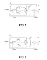
- FIG. 5 illustrates a preferred embodiment of a section of the control module of the DC/AC converter apparatus according to the present invention, the grid power injection regulator;
- FIG. 6 illustrates a preferred embodiment of a section of the control module of the DC/AC converter apparatus according to the present invention, the VAR regulator;
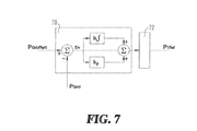
- FIG. 7 illustrates a preferred embodiment of a section of the control module of the DC/AC converter apparatus according to the present invention, the power consumption regulator.
- the DC/AC converter apparatus is adapted to convert an input DC voltage from a DC voltage source into an AC voltage to supply an AC load and to be fed into a utility grid, and it is further adapted to automatically control the amount of reactive power that is exchanged with said utility grid in order to keep the power factor above a predetermined threshold.
- the DC voltage source may, for example, be a renewable source of energy like a photovoltaic system or a wind power system, but it may also be a fuel cell or a battery.
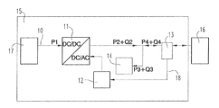
- FIG. 1 illustrates a typical installation of a first preferred embodiment of the DC/AC converter apparatus according to the present invention in a residential micro grid 15 .
- Home loads 14 may comprise a significant reactive part requiring a reactive power Q 3 in addition to the active power P 3 .
- a bidirectional power meter 13 is adapted to measure both the active P 4 and the reactive Q 4 power that flow between the micro grid 15 and the utility grid 16 .
- the DC/AC converter apparatus can read, through suitable communication line, the power meter 13 and produce an active power P 2 —preferably employing, in case of photovoltaic source, an MPPT algorithm, thus maximizing the power flow from said renewable source P 1 —and a reactive power Q 2 .
- the control module of the DC/AC converter apparatus will automatically produce the amount of reactive power Q 2 necessary to balance the home loads reactive power Q 3 demand, thus cancelling the reactive power Q 4 that needs to be exchanged with the utility grid.
- the utility grid will not be affected by the home reactive loads, the residential micro grid will thus exchange only active power with the utility grid keeping the overall power factor close to 1 and avoiding the extra cost of power factor charge.
- a first preferred embodiment of the DC/AC converter apparatus comprises:
- Input terminals 10 adapted to connect to a DC voltage source 17 preferably comprising a renewable DC voltage source;
- An inverter module adapted to convert the voltage of said DC voltage source into an AC voltage for supplying a load and for delivering to a utility grid;
- a control module 12 adapted to manage and regulate the operation of said inverter module, said control module 12 being preferably associated to a user interface;
- Power meter means for measuring the active and reactive electrical power flowing to and from the utility grid, said means for measuring active and reactive electrical power being associated to said control module 12 .
- Said means for measuring active and reactive electrical power preferably comprise a bidirectional power meter device 13 suitably connected to said control module 12 , through a wired or wireless data connection 18 , for sending and receiving data related to the performed measurements and control settings.
- Said inverter module may comprise a single stage or a double stage DC/AC inverter, said double stage DC/AC inverter comprising a DC/DC converter 11 and a cascaded DC/AC inverter 11 bis.
- the DC/DC converter is adapted to boost and/or regulate the DC voltage from the renewable DC voltage source in order to make it more stable and to optimize the power transfer from the renewable DC voltage source, preferably employing, in case of photovoltaic source, a suitable MPPT (Maximum Power Point Tracking) algorithm according to techniques well known in the art.
- MPPT Maximum Power Point Tracking
- the cascaded DC/AC inverter is adapted to convert the DC voltage from said upstream DC/DC converter into an AC voltage adapted to be delivered to the utility grid and to supply AC loads within the micro grid.
- the control module 12 by suitably interacting with said power meter means and with said DC/AC converter apparatus, is adapted to regulate the operation of said DC/AC converter apparatus in order to:
- non-export The optimal situation where the micro grid does not deliver energy to the utility grid at all is often referred to as “non-export”, “zero export”, “zero injection”, “zero immission to grid” etc.
- control module 12 of the apparatus allows adjusting the operation of said DC/AC converter apparatus so that the combination of the value of the active and reactive power produced by said DC/AC converter apparatus and of the value of the active and reactive power exchanged by said DC/AC converter apparatus with the utility grid, is approximately equal to a required value.
- said DC/AC converter apparatus further comprises
- Said control module 12 implements a double regulation loop, an output current regulation loop and an input voltage regulation loop.
- the output current regulation loop is based on a current controller 31 adapted to sense the output AC current of the DC/AC converter apparatus I Out and control the generation of instantaneous output current of said DC/AC inverter 11 bis according to the sensed current.
- the generation of instantaneous output current of DC/AC inverter 11 bis is controlled such that the output AC current follows the reference current I Ref .
- the input voltage regulation loop is based on a voltage controller 30 adapted to sense the input voltage of said DC/AC inverter 11 bis (output voltage of said DC/DC converter) and control the generation of the reference current I Ret with which the sensed current I Out is compared.
- the input voltage regulation loop can be further adapted to match the input voltage to a reference point provided by a suitable MPPT algorithm according to techniques well known to the person skilled in the art.
- said control module 12 comprises an active power controller 21 and a reactive power controller 22 placed between said output current regulation loop and said input voltage regulation loop.
- FIG. 3 shows a first preferred embodiment of said control module 12 comprising:
- Said control module 12 is adapted to control the operation of the DC/AC converter apparatus according to the present invention by providing current regulation which drives the DC/AC inverter 11 bis to operate in the one or more pre-defined modes.
- a control operation of said control module 12 senses the current I Out at the output of the DC-AC inverter 11 bis . Thereafter, the current I Out is provided to the current controller 31 that compares the sensed current I Out and a reference current I Ret .
- the reference current I Ret comprises a current magnitude and a current wave shape information and it represents the current that is required to flow into the load 14 and into the AC grid 16 .
- said reference current I Ref is generated with the contribution of said voltage controller 30 , said active power controller 21 and said reactive power controller 22 .
- the voltage controller 30 is adapted to sense the input voltage of said DC/AC inverter 11 bis (output voltage of said DC/DC converter), compare it with a reference voltage V DClinkRef and control the generation of a second reference current I 2Ref .
- the second reference current I 2Ref is then fed to said active power controller 21 together with a reference value of a first active output power P gridRef .
- the active power controller 21 senses, from said bidirectional power meter device 13 , the actual active output power P grid and processes it together with the second current reference I 2Ref and said first active power reference P gridRef to calculate a third current reference I 3Ref .
- the third current reference I 3Ref is then fed to said reactive power controller 22 together with a reference value of reactive output power Q gridRef .
- the reactive gridRef power controller 22 senses, from said bidirectional power meter device 13 , the actual reactive output power Q grid and processes it together with the second reference data I d2Ref and a reactive power reference Q gridRef to calculate said reference current I Ref .
- the active power controller 21 comprises a grid power injection regulator 26 and a current clipper module 27 .
- the grid power injection regulator 26 is adapted to sense, from said bidirectional power meter device 13 , the actual active output power P grid and compare it with a reference value of active output power P gridRef , the result is further processed to generate a first auxiliary current reference I lim which is fed to said current clipper module 27 to be compared with said second reference current I 2Ref generated by said voltage controller 30 .
- the comparison within current clipper module 27 generates said third current reference I 3Ref .
- the reactive power controller 22 comprises a VAR regulator 28 and a current reference generator module 29 .
- the VAR regulator 28 is adapted to sense, from said bidirectional power meter device 13 , the actual reactive output power Q grid and compare it with a reference value of reactive output power Q gridRef , the result is further processed to generate a second auxiliary current reference I q which is fed to said current reference generator module 29 to be compared with said third reference current I 3Ref generated by said active power controller 21 .
- the result of that comparison generates said reference current I Ref to be processed by said current controller 31 to close the current regulation loop of said DC/AC inverter 11 bis.
- the positions of said active power controller 21 and reactive power controller 22 can be exchanged within the control loop of the control module 12 , without departing from the scope of the invention and in order to prioritize the active power regulation over the reactive power regulation or vice-versa.
- a second preferred embodiment of the apparatus according to the present invention further comprises a battery module 20 and a battery charger 19 .
- said control module 12 further comprises a battery power manager 23 .
- Said battery module 20 and battery power manager 23 allow adding to the DC/AC converter apparatus according to the present invention further flexibility towards the optimization of the power usage of the micro grid.
- the battery power manager 23 is adapted to control the charge and discharge operation of the battery charger 19 according to the settings and the requirements by the user.
- the battery power manager 23 will set the battery charger 19 in its charge mode in order to store the energy excess into the battery module 20 .
- the battery power manager 23 will set the battery charger 19 in its discharge mode in order to convey the energy previously stored in said battery module 20 to said inverter module to be supplied to the local loads.
- the battery power manager 23 comprises a power consumption regulator 25 and a battery power controller 24 .
- the power consumption regulator 25 is adapted to sense, from said bidirectional power meter device 13 , the actual active output power P grid and compare it with a second reference value of active output power P GridRef1 . The result is further processed to generate an intermediate battery power reference P 1Ref . Said intermediate battery power reference P 1Ref is then fed to the battery power controller 24 to be compared with the actual battery power P Batt , the power being delivered to or from said battery module 20 as sensed by said battery power controller 24 . The result of the comparison leads to the generation of a battery power reference P BattRef that will be fed to said battery charger 19 to close the battery charger power regulation loop and drive the battery module 20 to charge or discharge mode according to the setting requirements.
- said grid power injection regulator 26 preferably comprises a proportional-integral controller (P-I controller) 50 adapted to calculate an error value (Err) as the difference between a measured process variable (P grid ) and a desired setpoint (P gridRef ).
- the P-I controller 50 attempts to minimize said error by adjusting the process through use of its output manipulated variable.
- a multiplier block 51 is cascaded to said P-I controller 50 adapted to multiply the P-I controller 50 output variable by the inverse of the grid voltage in order to get to the first auxiliary current reference value I lim .
- a saturation block 52 is preferably connected to the output of the P-I controller 50 in order to limit the output signal of said P-I controller 50 to a maximum value compatible with the hardware features of the DC/AC converter apparatus.
- Said current clipper module 27 can be implemented by a simple comparator adapted to detect and output said third auxiliary current reference value I 3Ref as the lower between said first auxiliary current reference I lim and said second current reference I 2Ref .
- Said VAR regulator 28 preferably comprises a P-I controller 60 cascaded by a multiplier block 61 .
- the P-I controller 60 processes variables and setpoints expressed in terms of reactive power and the multiplier block 61 is adapted to multiply the P-I controller 60 output variable by the inverse of the grid voltage in order to get to said second auxiliary current reference I q .
- Said current reference generator module 29 preferably comprises a sinusoidal signal adder adapted to calculate said reference current I Ref through the combination of two input signals, said second auxiliary current reference I q and said third auxiliary current reference I 3Ref according to the equation:
- I Ref ⁇ square root over (( I 3Ref) 2 +( Iq ) 2 ) ⁇ .
- said power consumption regulator 25 preferably comprises a P-I controller 70 .
- the P-I controller 70 processes variables and setpoints expressed in terms of active power.
- a saturation block 72 is preferably connected to the output of the P-I controller 70 in order to limit the output signal of said P-I controller 70 to a maximum value compatible with the hardware features of the DC/AC converter apparatus.
- the actual active output power P grid and the reference value of active output power P GridRef1 are processed to generate an intermediate battery power reference P 1Ref .
- Said intermediate battery power reference P 1Ref is then fed to the battery power controller 24 to be compared with the actual battery power P Batt , sensed by the battery power controller 24 .
- the result of the comparison leads to the generation of a battery power reference P BattRef that will be fed to said battery charger 19 to close the battery charger power regulation loop and drive the battery module 20 to charge or discharge mode according to the setting requirements.
Abstract
Description
- The present invention relates to a DC/AC converter apparatus and to a power conversion and generation system comprising such DC/AC converter apparatus. In particular, but not exclusively, the present invention relates to DC/AC conversion systems of the electrical power generated by photovoltaic systems and adapted to be connected directly to the power grid.
- Distributed generation of energy is based on the integration of small-sized and medium-sized power generators which use new and renewable energy generation technologies—such as solar, wind, and fuel cells—to provide power to local users and to a utility grid. While conventional power stations, such as coal-fired, gas and nuclear powered plants, as well as hydroelectric dams and large-scale solar power stations, are centralized and often require electricity to be transmitted to the users over long distances, distributed generation systems are decentralized, modular, more flexible and located close to the load they serve, albeit having smaller capacities.
- The distributed generation systems generally employ one or more micro grids for generating power. Micro grids are localized power generation systems that operate in connection with the utility grid. Said micro grids may work either connected to or disconnected from the main grid. When they are connected to the main grid they provide power to said main grid and to the connected loads, when they are disconnected from the main grid they function autonomously in an isolated mode, supplying only the connected load.
- One example of micro grid is based on solar inverters, widely used for generating electrical energy in distributed generation systems by converting solar energy collected by solar cell panels. Said solar inverters are adapted to convert the DC input voltage generated from the solar cell panels into an AC output voltage characterized by amplitude and frequency as required by the power grid specifications. The DC/AC conversion provided by said solar inverters generally comprises two stages: a first DC/DC conversion to boost and regulate the DC voltage from the solar cell panels, and a second DC/AC conversion to provide the requested AC power. The first DC/DC conversion is generally accomplished by a booster DC/DC converter whereas said second conversion is generally accomplished by a DC/AC converter based on a high-frequency Pulse Width Modulation (PWM) inverter. Same topologies are successfully employed with DC power input from wind turbines or fuel cells as well.
- On one side distributed generation systems offer great flexibility and means to manage the consumption of electrical power from the utility grid through the production of local electrical power at the micro grid. The active electrical power produced at the micro grid can be either consumed locally or provided to the utility grid thus reducing the overall consumption of the electrical power from the utility grid.
- On the other side micro grid are not so convenient regarding reactive electrical power.
- In alternating current (AC) circuits, reactive power is defined as the portion of power due to energy stored in inductors and capacitors of the circuit, which returns to the source in each cycle. If the load supplied by said source is purely resistive, voltage and current on the load are in phase, at every instant the product of voltage and current is positive, indicating that the direction of energy flow does not reverse, and the power on the load is only of active type. If the load supplied by said source is purely reactive, that is comprising only inductors or capacitors, then the voltage and current are 90 degrees out of phase. For half of each cycle, the product of voltage and current is positive, but on the other half of the cycle, the product is negative, indicating that on average, exactly as much energy flows toward the load as flows back. There is no net energy flow over one cycle. In this case, only reactive power flows and there is no active power transfer to the load. In practical cases loads have resistance, inductance, and capacitance, so both active and reactive power will flow to real loads. In this case apparent power is often measured, which is the magnitude of the vector sum of active and reactive power. The ratio between active power (usually measured in kilowatts, kW) and apparent power (usually measured in kilovolt-amperes, kVA) is called the power factor. Power factor ranges from 0 (for circuits comprising only inductors or capacitors) to 1 (for circuits comprising only resistors).
- Utility grids provide the active power to their users and manage the reactive power flow as well. Reactive power flow, mostly due to electrical motors and fluorescent lamp ballasts, strongly influences the voltage levels and the losses across the network, therefore reactive power flow must be carefully controlled and limited to allow a power system to be operated properly, minimizing the network energy losses and ultimately the amount of greenhouse gases that are released into the atmosphere.
- Managing the reactive power is a cost for the electric utility and therefore users may be charged if the loads they supply are such as causing relevant amounts of reactive power. This is referred to as “power factor charge”. Electric utilities normally specify in their supply contracts a power factor lower limit for user's load not to be trespassed in order not to incur the costs of the reactive power exchanged between the user and the electric utility.
- Alternatively, users may be requested by the electric utility to produce a certain amount of reactive power in order to stay within the power factor requested limits and not to be charged for trespassing them.
- In the case of micro grids, the problem with reactive power is worse than for normal users. In fact, micro grids produce active power which is either consumed locally or sent to the utility grid. When the power produced by the micro grid is consumed locally to supply the local loads, the active power drawn by the utility grid decreases whereas the reactive power exchanged with said utility grid remains unchanged. As a result the power factor (equal to the ratio between active power and apparent power) decreases as well, possibly below the limit allowed by the utility and therefore a “power factor charge” might be applied to the micro grid user.
- Some of the state of the art DC/AC conversion systems offer reactive power control: in case the utility needs to adjust the reactive power balance across its network and issues a request for limiting the overall reactive power to a micro grid, the user can change the operating mode of the DC/AC conversion system of the micro grid in order to limit reactive power according to the applicable standard, such as, for instance, CEI-021 or VDE AR-N4105.
- In light of the situation outlined above, there is a need for an improved DC/AC converter apparatus, for converting DC power of a DC energy source into AC power for supplying a load and or the utility grid, while achieving automatic control of the amount of reactive power that is exchanged with said utility grid. Provided with automatic reactive power control, the DC/AC converter apparatus will not need to receive a request, by the utility manager, to provide reactive power in order to keep the power factor above a predetermined threshold. The reactive power of the micro grid local loads will be controlled and balanced real-time, at the grid connection point, with no need of intervention by the user. Moreover, the harmonic content of the produced AC power will be corrected and reduced accordingly.
- It is therefore an object of the present invention to introduce an improved DC/AC converter apparatus, for converting DC power of a DC energy source into AC power for supplying a load and or the utility grid, adapted to automatically control the amount of both active and reactive electrical power that is exchanged with the utility grid in order to optimize the electrical power usage of the micro grid.
- In terms of active power, optimizing the electrical power usage of the micro grid means:
-
- maximizing the amount of DC power from said renewable power source which is converted into AC power;
- maximizing the so-called self-consumption, defined as the ratio between the fraction of self-produced power (that is power produced within the micro grid) that is consumed by the user and the total amount of self-produced power;
- minimizing the exchange of reactive power between the micro grid and the utility grid.
- In terms of reactive power, optimizing the electrical power usage of the micro grid means keeping the power factor above a predetermined threshold.
- Further features and advantages of the present invention will be apparent in the following description of a non-limitative embodiment with reference to the figures in the accompanying drawings, which are diagrammatic and show functional blocks which are adapted to be made according to different circuitry solutions in practice. In detail:
-
FIG. 1 illustrates a schematic diagram of a first preferred embodiment of the DC/AC converter apparatus according to the present invention installed in a residential micro grid; -
FIG. 2 illustrates a schematic diagram of a second preferred embodiment of the DC/AC converter apparatus according to the present invention installed in a residential micro grid; -
FIG. 3 illustrates a schematic diagram of a first preferred embodiment of the DC/AC converter apparatus according to the present invention showing a first preferred embodiment of the controller of said DC/AC converter apparatus; -
FIG. 4 illustrates a schematic diagram of a second preferred embodiment of the apparatus according to the present invention showing a second preferred embodiment of the controller of said DC/AC converter apparatus; -
FIG. 5 illustrates a preferred embodiment of a section of the control module of the DC/AC converter apparatus according to the present invention, the grid power injection regulator; -
FIG. 6 illustrates a preferred embodiment of a section of the control module of the DC/AC converter apparatus according to the present invention, the VAR regulator; -
FIG. 7 illustrates a preferred embodiment of a section of the control module of the DC/AC converter apparatus according to the present invention, the power consumption regulator. - The DC/AC converter apparatus according to the present invention is adapted to convert an input DC voltage from a DC voltage source into an AC voltage to supply an AC load and to be fed into a utility grid, and it is further adapted to automatically control the amount of reactive power that is exchanged with said utility grid in order to keep the power factor above a predetermined threshold.
- The DC voltage source may, for example, be a renewable source of energy like a photovoltaic system or a wind power system, but it may also be a fuel cell or a battery.
- The accompanying
FIG. 1 illustrates a typical installation of a first preferred embodiment of the DC/AC converter apparatus according to the present invention in aresidential micro grid 15.Home loads 14 may comprise a significant reactive part requiring a reactive power Q3 in addition to the active power P3. Abidirectional power meter 13 is adapted to measure both the active P4 and the reactive Q4 power that flow between themicro grid 15 and theutility grid 16. - The DC/AC converter apparatus according to the present invention can read, through suitable communication line, the
power meter 13 and produce an active power P2—preferably employing, in case of photovoltaic source, an MPPT algorithm, thus maximizing the power flow from said renewable source P1—and a reactive power Q2. - The control module of the DC/AC converter apparatus according to the present invention will automatically produce the amount of reactive power Q2 necessary to balance the home loads reactive power Q3 demand, thus cancelling the reactive power Q4 that needs to be exchanged with the utility grid. This way the utility grid will not be affected by the home reactive loads, the residential micro grid will thus exchange only active power with the utility grid keeping the overall power factor close to 1 and avoiding the extra cost of power factor charge.
- With reference to enclosed
FIG. 1 , a first preferred embodiment of the DC/AC converter apparatus according to the present invention comprises: -
Input terminals 10 adapted to connect to aDC voltage source 17 preferably comprising a renewable DC voltage source; - An inverter module adapted to convert the voltage of said DC voltage source into an AC voltage for supplying a load and for delivering to a utility grid;
- A
control module 12 adapted to manage and regulate the operation of said inverter module, saidcontrol module 12 being preferably associated to a user interface; - Power meter means for measuring the active and reactive electrical power flowing to and from the utility grid, said means for measuring active and reactive electrical power being associated to said
control module 12. - Said means for measuring active and reactive electrical power preferably comprise a bidirectional
power meter device 13 suitably connected to saidcontrol module 12, through a wired orwireless data connection 18, for sending and receiving data related to the performed measurements and control settings. - Said inverter module may comprise a single stage or a double stage DC/AC inverter, said double stage DC/AC inverter comprising a DC/
DC converter 11 and a cascaded DC/AC inverter 11 bis. - The DC/DC converter is adapted to boost and/or regulate the DC voltage from the renewable DC voltage source in order to make it more stable and to optimize the power transfer from the renewable DC voltage source, preferably employing, in case of photovoltaic source, a suitable MPPT (Maximum Power Point Tracking) algorithm according to techniques well known in the art.
- The cascaded DC/AC inverter is adapted to convert the DC voltage from said upstream DC/DC converter into an AC voltage adapted to be delivered to the utility grid and to supply AC loads within the micro grid.
- The
control module 12, by suitably interacting with said power meter means and with said DC/AC converter apparatus, is adapted to regulate the operation of said DC/AC converter apparatus in order to: -
- maximize the amount of DC power from said renewable power source which is converted into AC power;
- maximize the so-called self-consumption, defined as the ratio between the fraction of self-produced power (that is power produced within the micro grid) that is consumed by the user and the total amount of self-produced power;
- minimize the amount of energy transferred from the micro grid to the utility grid;
- minimize the exchange of reactive power between the micro grid and the utility grid.
- The optimal situation where the micro grid does not deliver energy to the utility grid at all is often referred to as “non-export”, “zero export”, “zero injection”, “zero immission to grid” etc.
- In general terms, the
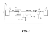
control module 12 of the apparatus according to the present invention allows adjusting the operation of said DC/AC converter apparatus so that the combination of the value of the active and reactive power produced by said DC/AC converter apparatus and of the value of the active and reactive power exchanged by said DC/AC converter apparatus with the utility grid, is approximately equal to a required value. - In a second preferred embodiment of the DC/AC converter apparatus according to the present invention, depicted in accompanying
FIG. 2 , said DC/AC converter apparatus further comprises -
- a battery-
charger module 19 associated to and adapted to charge - a
battery module 20 adapted to store power from said inverter module, during charge, and to supply energy to said inverter module during discharge. In both cases, thecontrol module 12 of the apparatus according to the present invention further manages to control the operation of said battery-charger module 19 and the charge and discharge of saidbattery module 20 in order to maximize the self-consumption within the micro grid: when the electrical power harvested from saidDC voltage source 17 exceeds the local load power needs, then it is fed to thebattery module 20 and stored. When the electrical power harvested from saidDC voltage source 17 falls short the local load power needs, then the energy previously stored in saidbattery module 20 is fed back to said inverter module to be supplied to the local loads.
- a battery-
- Said
control module 12 implements a double regulation loop, an output current regulation loop and an input voltage regulation loop. The output current regulation loop is based on acurrent controller 31 adapted to sense the output AC current of the DC/AC converter apparatus IOut and control the generation of instantaneous output current of said DC/AC inverter 11 bis according to the sensed current. The generation of instantaneous output current of DC/AC inverter 11 bis is controlled such that the output AC current follows the reference current IRef. - The input voltage regulation loop is based on a
voltage controller 30 adapted to sense the input voltage of said DC/AC inverter 11 bis (output voltage of said DC/DC converter) and control the generation of the reference current IRet with which the sensed current IOut is compared. The input voltage regulation loop can be further adapted to match the input voltage to a reference point provided by a suitable MPPT algorithm according to techniques well known to the person skilled in the art. - Furthermore, with reference to the accompanying
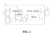
FIG. 3 , illustrating a first preferred embodiment of the apparatus according to the present invention showing a first preferred embodiment of thecontrol module 12 of said DC/AC converter apparatus according to the present invention, saidcontrol module 12 comprises anactive power controller 21 and areactive power controller 22 placed between said output current regulation loop and said input voltage regulation loop. - In greater detail, enclosed
FIG. 3 shows a first preferred embodiment of saidcontrol module 12 comprising: -
- a
current controller 31 adapted to sense the output AC current of said inverter module IOut (output AC current of said DC/AC inverter 11 bis) and control the generation of instantaneous output current of said inverter module (output AC current of said DC/AC inverter 11 bis) according to the sensed current and to a reference current value IRef; - a
voltage controller 30 adapted to sense the input voltage of said DC/AC inverter 11 bis (output voltage of said DC/DC converter) and control the generation of the reference current IRet with which the sensed current IOut is compared; - an
active power controller 21 adapted to control the active power output of the DC/AC converter apparatus according to the present invention and - a
reactive power controller 22 adapted to control the reactive power output of the DC/AC converter apparatus according to the present invention.
- a
- Said
control module 12 is adapted to control the operation of the DC/AC converter apparatus according to the present invention by providing current regulation which drives the DC/AC inverter 11 bis to operate in the one or more pre-defined modes. A control operation of saidcontrol module 12 senses the current IOut at the output of the DC-AC inverter 11 bis. Thereafter, the current IOut is provided to thecurrent controller 31 that compares the sensed current IOut and a reference current IRet. The reference current IRet comprises a current magnitude and a current wave shape information and it represents the current that is required to flow into theload 14 and into theAC grid 16. According to the present invention, said reference current IRef is generated with the contribution of saidvoltage controller 30, saidactive power controller 21 and saidreactive power controller 22. - The
voltage controller 30 is adapted to sense the input voltage of said DC/AC inverter 11 bis (output voltage of said DC/DC converter), compare it with a reference voltage VDClinkRef and control the generation of a second reference current I2Ref. - The second reference current I2Ref is then fed to said
active power controller 21 together with a reference value of a first active output power PgridRef. Theactive power controller 21 senses, from said bidirectionalpower meter device 13, the actual active output power Pgrid and processes it together with the second current reference I2Ref and said first active power reference PgridRef to calculate a third current reference I3Ref. - The third current reference I3Ref is then fed to said
reactive power controller 22 together with a reference value of reactive output power QgridRef. The reactivegridRef power controller 22 senses, from said bidirectionalpower meter device 13, the actual reactive output power Qgrid and processes it together with the second reference data Id2Ref and a reactive power reference QgridRef to calculate said reference current IRef. - In greater detail, the
active power controller 21 comprises a gridpower injection regulator 26 and acurrent clipper module 27. The gridpower injection regulator 26 is adapted to sense, from said bidirectionalpower meter device 13, the actual active output power Pgrid and compare it with a reference value of active output power PgridRef, the result is further processed to generate a first auxiliary current reference Ilim which is fed to saidcurrent clipper module 27 to be compared with said second reference current I2Ref generated by saidvoltage controller 30. The comparison withincurrent clipper module 27 generates said third current reference I3Ref. - The
reactive power controller 22 comprises aVAR regulator 28 and a currentreference generator module 29. TheVAR regulator 28 is adapted to sense, from said bidirectionalpower meter device 13, the actual reactive output power Qgrid and compare it with a reference value of reactive output power QgridRef, the result is further processed to generate a second auxiliary current reference Iq which is fed to said currentreference generator module 29 to be compared with said third reference current I3Ref generated by saidactive power controller 21. The result of that comparison generates said reference current IRef to be processed by saidcurrent controller 31 to close the current regulation loop of said DC/AC inverter 11 bis. - The positions of said
active power controller 21 andreactive power controller 22 can be exchanged within the control loop of thecontrol module 12, without departing from the scope of the invention and in order to prioritize the active power regulation over the reactive power regulation or vice-versa. - With reference to the accompanying
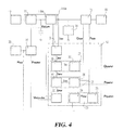
FIG. 4 , a second preferred embodiment of the apparatus according to the present invention further comprises abattery module 20 and abattery charger 19. Accordingly, saidcontrol module 12 further comprises abattery power manager 23. Saidbattery module 20 andbattery power manager 23 allow adding to the DC/AC converter apparatus according to the present invention further flexibility towards the optimization of the power usage of the micro grid. - The
battery power manager 23 is adapted to control the charge and discharge operation of thebattery charger 19 according to the settings and the requirements by the user. - If the requirement is to maximize the self-consumption within the micro grid, when the electrical power harvested from said
DC voltage source 17 exceeds the local load power needs, then thebattery power manager 23 will set thebattery charger 19 in its charge mode in order to store the energy excess into thebattery module 20. When, on the opposite, the electrical power harvested from saidDC voltage source 17 falls short the local load power needs, then thebattery power manager 23 will set thebattery charger 19 in its discharge mode in order to convey the energy previously stored in saidbattery module 20 to said inverter module to be supplied to the local loads. - In greater detail and with reference to accompanying
FIG. 4 , thebattery power manager 23 comprises apower consumption regulator 25 and abattery power controller 24. Thepower consumption regulator 25 is adapted to sense, from said bidirectionalpower meter device 13, the actual active output power Pgrid and compare it with a second reference value of active output power PGridRef1. The result is further processed to generate an intermediate battery power reference P1Ref. Said intermediate battery power reference P1Ref is then fed to thebattery power controller 24 to be compared with the actual battery power PBatt, the power being delivered to or from saidbattery module 20 as sensed by saidbattery power controller 24. The result of the comparison leads to the generation of a battery power reference PBattRef that will be fed to saidbattery charger 19 to close the battery charger power regulation loop and drive thebattery module 20 to charge or discharge mode according to the setting requirements. - In further detail, with reference to accompanying
FIGS. 5 to 7 , said gridpower injection regulator 26 preferably comprises a proportional-integral controller (P-I controller) 50 adapted to calculate an error value (Err) as the difference between a measured process variable (Pgrid) and a desired setpoint (PgridRef). TheP-I controller 50 attempts to minimize said error by adjusting the process through use of its output manipulated variable. Being said P-I controller processes variables and setpoints expressed in terms of power, amultiplier block 51 is cascaded to saidP-I controller 50 adapted to multiply theP-I controller 50 output variable by the inverse of the grid voltage in order to get to the first auxiliary current reference value Ilim. Furthermore asaturation block 52 is preferably connected to the output of theP-I controller 50 in order to limit the output signal of saidP-I controller 50 to a maximum value compatible with the hardware features of the DC/AC converter apparatus. - Said
current clipper module 27 can be implemented by a simple comparator adapted to detect and output said third auxiliary current reference value I3Ref as the lower between said first auxiliary current reference Ilim and said second current reference I2Ref. - Said
VAR regulator 28 preferably comprises aP-I controller 60 cascaded by amultiplier block 61. TheP-I controller 60 processes variables and setpoints expressed in terms of reactive power and themultiplier block 61 is adapted to multiply theP-I controller 60 output variable by the inverse of the grid voltage in order to get to said second auxiliary current reference Iq. Theprocessing block 62 is adapted to calculate the maximum allowable reactive power as: qMax=√{square root over ((SMax)2−(P)2)}, wherein SMax is the maximum value of apparent power, P is the actual value of active power and Qmax is the resulting maximum allowable reactive power from the DC/AC converter apparatus. - Said current
reference generator module 29 preferably comprises a sinusoidal signal adder adapted to calculate said reference current IRef through the combination of two input signals, said second auxiliary current reference Iq and said third auxiliary current reference I3Ref according to the equation: -
I Ref=√{square root over ((I3Ref)2+(Iq)2)}. - Finally, said
power consumption regulator 25 preferably comprises aP-I controller 70. TheP-I controller 70 processes variables and setpoints expressed in terms of active power. Asaturation block 72 is preferably connected to the output of theP-I controller 70 in order to limit the output signal of saidP-I controller 70 to a maximum value compatible with the hardware features of the DC/AC converter apparatus. - As explained before, the actual active output power Pgrid and the reference value of active output power PGridRef1 are processed to generate an intermediate battery power reference P1Ref. Said intermediate battery power reference P1Ref is then fed to the
battery power controller 24 to be compared with the actual battery power PBatt, sensed by thebattery power controller 24. The result of the comparison leads to the generation of a battery power reference PBattRef that will be fed to saidbattery charger 19 to close the battery charger power regulation loop and drive thebattery module 20 to charge or discharge mode according to the setting requirements.
Claims (20)
Q Max=√{square root over ((S Max)2−(P)2)}
Q Max=√{square root over ((S Max)2−(P)2)}
Applications Claiming Priority (3)
| Application Number | Priority Date | Filing Date | Title |
|---|---|---|---|
| EP15179469.0 | 2015-08-03 | ||
| EP15179469 | 2015-08-03 | ||
| EP15179469.0A EP3128637A1 (en) | 2015-08-03 | 2015-08-03 | Dc/ac converter apparatus comprising means for controlling the reactive power and power conversion and generation system comprising such dc/ac converter apparatus |
Publications (2)
| Publication Number | Publication Date |
|---|---|
| US20170040887A1 true US20170040887A1 (en) | 2017-02-09 |
| US10211721B2 US10211721B2 (en) | 2019-02-19 |
Family
ID=53773344
Family Applications (1)
| Application Number | Title | Priority Date | Filing Date |
|---|---|---|---|
| US15/227,544 Active 2037-03-09 US10211721B2 (en) | 2015-08-03 | 2016-08-03 | DC/AC converter apparatus comprising means for controlling the reactive power and power conversion and generation system comprising such DC/AC converter apparatus |
Country Status (4)
| Country | Link |
|---|---|
| US (1) | US10211721B2 (en) |
| EP (1) | EP3128637A1 (en) |
| AU (1) | AU2016208284B2 (en) |
| BR (1) | BR102016017984A2 (en) |
Cited By (6)
| Publication number | Priority date | Publication date | Assignee | Title |
|---|---|---|---|---|
| US20170104333A1 (en) * | 2015-10-07 | 2017-04-13 | General Electric Company | Solar power conversion system and method |
| EP3575805A1 (en) * | 2018-05-30 | 2019-12-04 | ALSTOM Transport Technologies | Dc substation and method for detecting an electrical energy flow in said substation |
| CN112531772A (en) * | 2020-11-27 | 2021-03-19 | 珠海格力电器股份有限公司 | Reactive power control method, device and system, storage medium and electronic device |
| CN113013917A (en) * | 2021-02-05 | 2021-06-22 | 浙江大学 | Hybrid phase synchronization controller and control method for power electronic converter |
| CN113285462A (en) * | 2021-05-28 | 2021-08-20 | 南方电网电力科技股份有限公司 | Intelligent voltage stabilizing device of power transmission line, control method, equipment and medium |
| EP4207532A1 (en) * | 2021-12-30 | 2023-07-05 | Wanbang Digital Energy Co., Ltd. | Grid-tied power generation system and grid-tied power fluctuation suppression device and method thereof |
Families Citing this family (7)
| Publication number | Priority date | Publication date | Assignee | Title |
|---|---|---|---|---|
| WO2018108277A1 (en) * | 2016-12-15 | 2018-06-21 | Abb Schweiz Ag | Method for detecting islanding conditions for a dc/ac converter apparatus and a dc/ac converter apparatus thereof |
| CN106877355B (en) * | 2017-03-30 | 2019-06-28 | 南方电网科学研究院有限责任公司 | A kind of reactive compensation adjusting method |
| EP4007106A4 (en) * | 2019-07-23 | 2023-05-03 | Toshiba Mitsubishi-Electric Industrial Systems Corporation | Power conversion device and distributed power source system |
| EP4007107B1 (en) * | 2019-07-23 | 2024-05-01 | Toshiba Mitsubishi-Electric Industrial Systems Corporation | Power conversion device and distributed power supply system |
| CA3174426A1 (en) | 2020-04-02 | 2021-10-07 | Abhineet H. PARCHURE | Electrical grid control systems and methods using dynamically mapped effective impedance |
| CN114123288B (en) * | 2021-11-30 | 2023-11-21 | 国网河南省电力公司直流运检分公司 | Method for determining optimal reactive power exchange quantity between converter station and alternating current power grid |
| CN115085175B (en) * | 2022-07-28 | 2023-05-23 | 广东电网有限责任公司电力调度控制中心 | AC/DC coordination control method, device, equipment and readable storage medium in power grid |
Citations (3)
| Publication number | Priority date | Publication date | Assignee | Title |
|---|---|---|---|---|
| US20170187303A1 (en) * | 2015-12-23 | 2017-06-29 | Abb Schweiz Ag | Dc/ac converter comprising control means for inrush current protection |
| US9787170B2 (en) * | 2012-02-13 | 2017-10-10 | Mitsubishi Electric Corporation | Power conversion device |
| US9912150B2 (en) * | 2013-07-10 | 2018-03-06 | Mitsubishi Electric Corporation | Power control system |
Family Cites Families (1)
| Publication number | Priority date | Publication date | Assignee | Title |
|---|---|---|---|---|
| JP2014033539A (en) * | 2012-08-03 | 2014-02-20 | Sharp Corp | Power controller, method, and program |
-
2015
- 2015-08-03 EP EP15179469.0A patent/EP3128637A1/en not_active Withdrawn
-
2016
- 2016-07-26 AU AU2016208284A patent/AU2016208284B2/en active Active
- 2016-08-03 BR BR102016017984A patent/BR102016017984A2/en not_active Application Discontinuation
- 2016-08-03 US US15/227,544 patent/US10211721B2/en active Active
Patent Citations (3)
| Publication number | Priority date | Publication date | Assignee | Title |
|---|---|---|---|---|
| US9787170B2 (en) * | 2012-02-13 | 2017-10-10 | Mitsubishi Electric Corporation | Power conversion device |
| US9912150B2 (en) * | 2013-07-10 | 2018-03-06 | Mitsubishi Electric Corporation | Power control system |
| US20170187303A1 (en) * | 2015-12-23 | 2017-06-29 | Abb Schweiz Ag | Dc/ac converter comprising control means for inrush current protection |
Cited By (8)
| Publication number | Priority date | Publication date | Assignee | Title |
|---|---|---|---|---|
| US20170104333A1 (en) * | 2015-10-07 | 2017-04-13 | General Electric Company | Solar power conversion system and method |
| US9997921B2 (en) * | 2015-10-07 | 2018-06-12 | General Electric Company | Solar power conversion system and method |
| EP3575805A1 (en) * | 2018-05-30 | 2019-12-04 | ALSTOM Transport Technologies | Dc substation and method for detecting an electrical energy flow in said substation |
| CN112531772A (en) * | 2020-11-27 | 2021-03-19 | 珠海格力电器股份有限公司 | Reactive power control method, device and system, storage medium and electronic device |
| CN113013917A (en) * | 2021-02-05 | 2021-06-22 | 浙江大学 | Hybrid phase synchronization controller and control method for power electronic converter |
| CN113285462A (en) * | 2021-05-28 | 2021-08-20 | 南方电网电力科技股份有限公司 | Intelligent voltage stabilizing device of power transmission line, control method, equipment and medium |
| EP4207532A1 (en) * | 2021-12-30 | 2023-07-05 | Wanbang Digital Energy Co., Ltd. | Grid-tied power generation system and grid-tied power fluctuation suppression device and method thereof |
| US11799289B2 (en) | 2021-12-30 | 2023-10-24 | Wanbang Digital Energy Co., Ltd. | Grid-tied power generation system and grid-tied power fluctuation suppression device and method thereof |
Also Published As
| Publication number | Publication date |
|---|---|
| EP3128637A1 (en) | 2017-02-08 |
| US10211721B2 (en) | 2019-02-19 |
| AU2016208284B2 (en) | 2021-02-11 |
| BR102016017984A2 (en) | 2017-02-21 |
| AU2016208284A1 (en) | 2017-02-23 |
Similar Documents
| Publication | Publication Date | Title |
|---|---|---|
| US10211721B2 (en) | DC/AC converter apparatus comprising means for controlling the reactive power and power conversion and generation system comprising such DC/AC converter apparatus | |
| CN102170241B (en) | System and method for a single stage power conversion system | |
| Ganesan et al. | Control scheme for a bidirectional converter in a self-sustaining low-voltage DC nanogrid | |
| CN102570868B (en) | System and method for power conversion | |
| Kotra et al. | Energy management of hybrid microgrid with hybrid energy storage system | |
| CN106887847B (en) | A kind of micro-capacitance sensor and its operation method of the control of variable frequency transformer direct load | |
| US20160181809A1 (en) | Grid system conducive to enhancement of power supply performance | |
| Arjun Kumar et al. | Design and control of grid-connected solar-wind integrated conversion system with DFIG supplying three-phase four-wire loads | |
| Gb et al. | Design and control of grid-connected solar-wind integrated conversion system with DFIG supplying three-phase four-wire loads | |
| Bajestan et al. | Control of a new stand-alone wind turbine-based variable speed permanent magnet synchronous generator using quasi-Z-source inverter | |
| WO2020211307A1 (en) | Building full-direct-current power supply and electricity storage system and control method | |
| US11929690B2 (en) | Microgrid controller with one or more sources | |
| Hu et al. | Model predictive control of smart microgrids | |
| CN103280835A (en) | Method for controlling power generation state of three-phase grid-connected photovoltaic inverter | |
| CN110572067B (en) | Island energy storage type power unit series micro-grid structure and control method | |
| Dehbonei et al. | A combined voltage controlled and current controlled" dual converter" for a weak grid connected photovoltaic system with battery energy storage | |
| Barbosa et al. | Distributed generation system using renewable energy sources and a new converter topology | |
| RU2695633C1 (en) | Modular electric power plant | |
| CN206807012U (en) | A kind of micro-capacitance sensor of variable frequency transformer direct load control | |
| Marti et al. | Frequency regulation strategy for modular two-stage grid-connected photovoltaic systems | |
| CN219875099U (en) | AC/DC hybrid micro-grid | |
| Rao et al. | A Novel Hybrid PV/FC Energy Management Scheme For Grid Connection And Islanded Operation Capabilities | |
| Kashyap et al. | Ancillary Services And Stability Analysis Of Distributed Generation System | |
| Sharma et al. | Optimal Design Analysis of Multimodal Hybrid AC/DC Microgrids | |
| US20210344198A1 (en) | Reactive Power Control Method for an Integrated Wind and Solar Power System |
Legal Events
| Date | Code | Title | Description |
|---|---|---|---|
| AS | Assignment |
Owner name: ABB SCHWEIZ AG, SWITZERLAND Free format text: ASSIGNMENT OF ASSIGNORS INTEREST;ASSIGNORS:BECATTINI, ANDREA;MACERINI, SAURO;REEL/FRAME:040943/0888 Effective date: 20161103 |
|
| STCF | Information on status: patent grant |
Free format text: PATENTED CASE |
|
| AS | Assignment |
Owner name: MARICI HOLDINGS THE NETHERLANDS B.V., NETHERLANDS Free format text: ASSIGNMENT OF ASSIGNORS INTEREST;ASSIGNOR:ABB SCHWEIZ AG;REEL/FRAME:054205/0806 Effective date: 20201009 |
|
| FEPP | Fee payment procedure |
Free format text: SURCHARGE FOR LATE PAYMENT, LARGE ENTITY (ORIGINAL EVENT CODE: M1554); ENTITY STATUS OF PATENT OWNER: LARGE ENTITY |
|
| MAFP | Maintenance fee payment |
Free format text: PAYMENT OF MAINTENANCE FEE, 4TH YEAR, LARGE ENTITY (ORIGINAL EVENT CODE: M1551); ENTITY STATUS OF PATENT OWNER: LARGE ENTITY Year of fee payment: 4 |