US1864591A - Thermionic device - Google Patents
Thermionic device Download PDFInfo
- Publication number
- US1864591A US1864591A US1182A US118225A US1864591A US 1864591 A US1864591 A US 1864591A US 1182 A US1182 A US 1182A US 118225 A US118225 A US 118225A US 1864591 A US1864591 A US 1864591A
- Authority
- US
- United States
- Prior art keywords
- cone
- plate
- compartment
- cathode
- current
- Prior art date
- Legal status (The legal status is an assumption and is not a legal conclusion. Google has not performed a legal analysis and makes no representation as to the accuracy of the status listed.)
- Expired - Lifetime
Links
Images

Classifications
-
- H—ELECTRICITY
- H01—ELECTRIC ELEMENTS
- H01J—ELECTRIC DISCHARGE TUBES OR DISCHARGE LAMPS
- H01J21/00—Vacuum tubes
- H01J21/20—Tubes with more than one discharge path; Multiple tubes, e.g. double diode, triode-hexode
-
- H—ELECTRICITY
- H01—ELECTRIC ELEMENTS
- H01J—ELECTRIC DISCHARGE TUBES OR DISCHARGE LAMPS
- H01J2893/00—Discharge tubes and lamps
- H01J2893/003—Tubes with plural electrode systems
Definitions
- My invention relates, in general, to electronlc devices and particularly to audion tubes used as detectors or amplifiers in radio work.
- the primary object of my invention is to provide an audion that may be energized by energy derived from a source of alternating current, suchas the usual light and powercircuit generall available.
- Another 0 ject of my invention is to provide an audion of novel construction embodying means for modifying an alternating current to render it suitable to energize the electron-emitting filament employed as the cathode.
- Another object of m invention is to provide a novel method 0 establishing an electron stream in a thermionic device.
- I provide a non-filamentary cathode which occupies the usual position however, within a cylindrical grid and plate.
- the cathode is of cone-shape, the base being supported upon a glass annulus which together with the cone serves as a partition to separate the tube into two compartments.
- One compartment constitutes the operating compartment containing the cone cathode, a grid and a plate.
- the other compartment contains a filament which is energized from an alternating current circuit, and which cooperates with the cone to constitute an electric valve.
- the cone thus serves as an anode for the filament and as a cathode for the grid and the plate.
- the cone extends into the active region of the operating compartment within the grid and the plate. On its inner surface it receives the electron stream from the filament and the current conducted by ionization. It is thus heated to incandescence and emits an electron stream from its outer surface into the active region within the grid and the late.
- a mo ified form of this tube comprises two valve compartments separated from the main operating compartment and also from each other.
- the cone is divided into two compartments by a partition of correspondin metal which is anchored in a glass artition between the valve compartments.
- igures 1 to 5, inclusive, illustrate schematically different modifications of tubes embodying 'my invention
- Figure 6 is a perspective view of the element common to both compartments of the tube illustrated in Fig. 2;
- Figures 7 and 8 illustrate the construction and arrangement of the cone-shaped electrode employed in the tubes illustrated in Fi ure' 4;
- igures 9 to 13, inclusive are front views, partially in elevation and partially in sec tion, of tubes embodying the features illustrated in Fi s. 1 to 5, inc.;
- the tube lllustrated in Fig. 1 comprises a vessel 60 divided into two compartments by a partition 61 consisting of a glass annulus 62 and a tungsten disk or plate 63 supported in the center thereof.
- the main compartment contains the usual grid 64 and plate 65.
- the other compartment which may be termed the auxiliary or control compartment, contains a filament 66 and some inert gas such as argon.
- the filament is energized from an alternating current circuit 20 through a transformer which is also connected through a resistor 27 to include the auxiliary chamber in a series circuit. The filament is thereby rendered incandescent and the target or plate 63 is heated by bombardment and by the current traversing it.
- the plate 63' should have an oxide coating on the surface in the operating compartment but not on the surface in the rectifying compartment.
- the plate will thus be rendered active at a temperature considerably lower than the operatin temperature of the filament. There will t erefore be less activity and electron emission from the uneoated surface-of the plate than from the filament.
- the rectifying character of the filament and the plate will therefore not be affected inasmuch as the potential diiference between them will be insuflicient to cause a reversal of current and a penetration of the highly active electron field near the filament.
- the striking potential necessary to cause a reversal would be of the order of 175 to 200 volts for about inch spacing.
- the voltage necessary to operate the rectifying compartment need only be somewhat in excess of the initial striking potential which would be about 25 to 30 volts for he same spacing.
- the operation is similar to that of the tungar batter chargin rectifier.
- i 3 is i ustrated a modified form in which t e plate or anode of the rectifying compartment is employed in the form of a hollow cone 68.
- the rim of the base of the cone is supported in the glass annular art-1- tion 62, and the apex of the cone exten s into the operating chamber where it serves as a nonfilamentary cathode and is surrounded by the usual grid and plate.
- the latter elements are preferably of the same shape as the conein order to present the minimum spacing between the cone and the plate.
- the portion at the apex will heat more quickly and retain its heat.
- the cross-section of the wall of the cone may be increasingly tapered to a small degree from the rim of the base to the apex to present a conductin path whose area will diminish less rapidly t an in the cone having a constant wall thickness.
- the apex will thus have more concentrated mass or body to retain the heat and maintain the temperature substantially even.
- Aheat-storage element 69 is provided which supplies heat to the cone 1 while no current is transmitted thereto throu h the rectifying compartment.
- ig. 2 is illustrated a modification which utilizes all current waves of both polarities, thereby supplying a continuous unidirectional current to the plate or anode, and maintaining the temperature more even.
- Two rectifying compartments are provided which are partitioned from the main compartment and from each other.
- the plate 70 embodies two portions 71 and 72 respectively disposed in the partitions 6 and 7 separating the several compartments.
- the filaments in the auxiliary compartments transmit current alternately to the plate 70 which is consequently energized continuously by unidirectional current.
- the value of the current transmitted may be controlled by the variable resistor 27 and the tem erature and electronemitting character of t e surface of the plate in the main compartment varied accordingly.
- Fig. 4 a modification embodying the conestructure 68 which is energized in accordance with the principle controlling the tube in Fig. 2.
- the cone is divided into two pockets or chambers by a artition 73 of correspondin metal. ach pocket communicates with t e corresponding rectifying comiartment and constitutes part thereof.
- the aments are supported within the respective pockets as close to the apex as is practicable, considering the design of the cone.
- the rim of the base of the cone is secured to the main glass partition 6 and the metal cone partition 73 is anchored in the auxiliary glass partition 7. In this structure the cone is traversed and heated by a continuous unidirectional current.
- Fig. 5 is illustrated a tube of modified form in which the electron-emitting element or cathode for the main operatin compartment is not electrically connecte in circuit with the rectifying unlts.
- the plate of each rectifying chamber consists of an annulus having a relatively large opening which registers with one surface of the portion 72 of the common element.
- the ener zed particles move from the filaments to t e annular elements with sufiicient velocity to pass through the opening and bombard the portion 72 which conducts heat to the portion 71 in the main compartment to render it active.
- This modification requires a greater amount of energy to operate it since only a portion of the ener y is transmitted to the common plate element y bombardment.
- Fig. 6 is a perspective view of the element or p ate 70 common to the three compartments of the tube illustrated in Figs. 2 and 5.
- Figs. 7 and 8 are views illustrating the disposition of the partition 73 in the cone and in the auxiliary partition 7 between the recti ing chambers. By means of the partition 3 in the cone and the glass partition 7, the two chambers are entirely separated.
- Figs. 9, 10 and 11 are shown the embodiment containing the featuresillustrated in Fig. 4.
- the view in Fig. 9 shows the disposition of the cone cathode 68 within the plate 78 oftruncated cone shape.
- the partition 73 is anchored in a glass partition 7 across the tube underneath the cone and its su orting annulus 62.
- e view in Fig. 10 is a side sectional view of the tube in Fig. 9 with parts broken away,
- the apex of the cone is connected to a base terminal through a conductor and support 82.
- the view inFig. 11 is a sectional view of I the tube in Fig. 10 taken along the line 1111 storage capacity of the cone and to the fact in the direction of the arrows.
- the vertical glass partition 7 cooperates with the cone partit1on to separate the rectifying compartments.
- the circuit connections correspond to those illustrated in Fig. 4.
- connection from the apex of the cone to an external circuit is made by a conductor 83 connected to the internal surface of the apex.
- connection is made by a conductor 82 connected to the external surface of the apex of the cone.
- an even constant temperature may be maintained, due to the heat that the heated air is pocketed in the cone.
- the outer surface of the cone may be coated with the commercial oxides as at present em-, ployed-to obtain high electron emission at relatively low temperatures.
- the heating and temperature of the cone may be controlled by the resistor 27 in the energizing circuit. By means of such a system a relatively large heating current may be supplied to the cone which permits of greater flexibility and regulation. By controlling the current traversing the rectifying filaments and also the current traversing the filament-cone circuit, the operating characteristics of the cone in the operating compartment may be readily controlled.
- thermionic tube comprising an audion and a full-wave rectifier, said full-wave rectifier havin heatable cathodes and a common anode whic is the cathode for the audion,
- an insulating barrier means isolating the I active -s aces surrounding said cathodes.
- a ll-wave rectifier comprislng a closed envelope containing two heatable cathodes
- co-operating anode means comprising two chamber enclosures respectively surrounding the active spaces surrounding the cathodes, and a dielectric medium adjacent the chamber enclosures to prevent current leakage bettgeen the active spaces adjacent to the oath- 0 es.
- An electron discharge device comprising a sealed glass envelope having a press therein, a plurality of thermionic cathodes supported from said press within said envelo e, an anode surrounding said cathodes and aving an outer surface adapted to function as an equi-potential cathode, means associated with said anode for forming a separate Sealed compartment enclosing said cathodes, means for dividing said separate enclosure into separate space discharge regions, each region having one cathode, and a control electrode and an anode disposed around said equi-potential cathode.
- An electron discharge device comprising a sealed glass envelope having a press therein, a plurality of thermionic cathodes supported thereon, a conical anode enclosing said cathodes and having an outer surface adapt-.
- ed to function as an equi-potential cathode means cooperating with said anode for forming a separate sealed chamber enclosing said cathodes, means for separatin said enclosed space into distinct space disc arge regions, and a control electrode and an anode disposed around said equi-potential cathode.
Landscapes
- Discharge Lamp (AREA)
Description
June 28, 1932. J. E. FOSTER THERMIONIC DEVICE 2 Sheets-Sheet 1 Filed Jan. 8, 1925 June 28, 1932. FOSTER 1,864,591
THERMIONIC DEVI GE Filed Jan. 8, 1925 2 Sheets-Sheet 2 INVENTO Patented June 28, 1932 UNITED STATES PATENT OFFICE JULIUS E. FOSTER, 0] PITTSBURGH, PENNSYLVANIA, ASBIGNOB 1'0 RADIO CORPORA- 'I'ION OF AMERICA, A CORPORATION 01' DELAWARE TEEBHIONIC DEVICE Application fled January 8, 1925. Serial No. 1,182.
My invention relates, in general, to electronlc devices and particularly to audion tubes used as detectors or amplifiers in radio work.
The primary object of my invention is to provide an audion that may be energized by energy derived from a source of alternating current, suchas the usual light and powercircuit generall available.
Another 0 ject of my invention is to provide an audion of novel construction embodying means for modifying an alternating current to render it suitable to energize the electron-emitting filament employed as the cathode.
Another object of m invention is to provide a novel method 0 establishing an electron stream in a thermionic device.
In a tube of one type embodyingmy invention, I provide a non-filamentary cathode which occupies the usual position however, within a cylindrical grid and plate. The cathode is of cone-shape, the base being supported upon a glass annulus which together with the cone serves as a partition to separate the tube into two compartments. One compartment constitutes the operating compartment containing the cone cathode, a grid and a plate. The other compartment contains a filament which is energized from an alternating current circuit, and which cooperates with the cone to constitute an electric valve. The cone thus serves as an anode for the filament and as a cathode for the grid and the plate. The cone extends into the active region of the operating compartment within the grid and the plate. On its inner surface it receives the electron stream from the filament and the current conducted by ionization. It is thus heated to incandescence and emits an electron stream from its outer surface into the active region within the grid and the late.
A mo ified form of this tube comprises two valve compartments separated from the main operating compartment and also from each other. The cone is divided into two compartments by a partition of correspondin metal which is anchored in a glass artition between the valve compartments. e
certain advantages of construction inherent in the foregoing types, is also illustrated and described herein. The principle of focusin energy waves upon the cathode is employed to establish an active condition conducive to electron emission.
The principles involved will be better apprehen ed upon consideration of the structures illustrated in the accompanying drawin s.
igures 1 to 5, inclusive, illustrate schematically different modifications of tubes embodying 'my invention;
Figure 6 is a perspective view of the element common to both compartments of the tube illustrated in Fig. 2;
Figures 7 and 8 illustrate the construction and arrangement of the cone-shaped electrode employed in the tubes illustrated in Fi ure' 4;
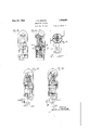
igures 9 to 13, inclusive, are front views, partially in elevation and partially in sec tion, of tubes embodying the features illustrated in Fi s. 1 to 5, inc.;
The tube lllustrated in Fig. 1 comprises a vessel 60 divided into two compartments by a partition 61 consisting of a glass annulus 62 and a tungsten disk or plate 63 supported in the center thereof. The main compartment contains the usual grid 64 and plate 65. The other compartment, which may be termed the auxiliary or control compartment, contains a filament 66 and some inert gas such as argon. The filament is energized from an alternating current circuit 20 through a transformer which is also connected through a resistor 27 to include the auxiliary chamber in a series circuit. The filament is thereby rendered incandescent and the target or plate 63 is heated by bombardment and by the current traversing it. The plate 63'should have an oxide coating on the surface in the operating compartment but not on the surface in the rectifying compartment. The plate will thus be rendered active at a temperature considerably lower than the operatin temperature of the filament. There will t erefore be less activity and electron emission from the uneoated surface-of the plate than from the filament. The rectifying character of the filament and the plate will therefore not be affected inasmuch as the potential diiference between them will be insuflicient to cause a reversal of current and a penetration of the highly active electron field near the filament. The striking potential necessary to cause a reversal would be of the order of 175 to 200 volts for about inch spacing. The voltage necessary to operate the rectifying compartment need only be somewhat in excess of the initial striking potential which would be about 25 to 30 volts for he same spacing. The operation is similar to that of the tungar batter chargin rectifier.
In i 3 is i ustrated a modified form in which t e plate or anode of the rectifying compartment is employed in the form of a hollow cone 68. The rim of the base of the cone is supported in the glass annular art-1- tion 62, and the apex of the cone exten s into the operating chamber where it serves as a nonfilamentary cathode and is surrounded by the usual grid and plate. The latter elements are preferably of the same shape as the conein order to present the minimum spacing between the cone and the plate.
Due to the decreasing cross-sectional area of the cone from the base to the apex, and the greater radiating surface near the base, the portion at the apex will heat more quickly and retain its heat.
The cross-section of the wall of the cone may be increasingly tapered to a small degree from the rim of the base to the apex to present a conductin path whose area will diminish less rapidly t an in the cone having a constant wall thickness. The apex will thus have more concentrated mass or body to retain the heat and maintain the temperature substantially even. Aheat-storage element 69 is provided which supplies heat to the cone 1 while no current is transmitted thereto throu h the rectifying compartment.
In ig. 2 is illustrated a modification which utilizes all current waves of both polarities, thereby supplying a continuous unidirectional current to the plate or anode, and maintaining the temperature more even. Two rectifying compartments are provided which are partitioned from the main compartment and from each other. The plate 70 embodies two portions 71 and 72 respectively disposed in the partitions 6 and 7 separating the several compartments. The filaments in the auxiliary compartments transmit current alternately to the plate 70 which is consequently energized continuously by unidirectional current. The value of the current transmitted may be controlled by the variable resistor 27 and the tem erature and electronemitting character of t e surface of the plate in the main compartment varied accordingly.
In Fig. 4 is illustrated a modification embodying the conestructure 68 which is energized in accordance with the principle controlling the tube in Fig. 2. The cone is divided into two pockets or chambers by a artition 73 of correspondin metal. ach pocket communicates with t e corresponding rectifying comiartment and constitutes part thereof. The aments are supported within the respective pockets as close to the apex as is practicable, considering the design of the cone. The rim of the base of the cone is secured to the main glass partition 6 and the metal cone partition 73 is anchored in the auxiliary glass partition 7. In this structure the cone is traversed and heated by a continuous unidirectional current.
By means of the partition in the cone as by the partition between the auxiliary compartments, any tendency to transmit 'current between both filaments is obviated.
In Fig. 5 is illustrated a tube of modified form in which the electron-emitting element or cathode for the main operatin compartment is not electrically connecte in circuit with the rectifying unlts. The plate of each rectifying chamber consists of an annulus having a relatively large opening which registers with one surface of the portion 72 of the common element. The ener zed particles move from the filaments to t e annular elements with sufiicient velocity to pass through the opening and bombard the portion 72 which conducts heat to the portion 71 in the main compartment to render it active. This modification requires a greater amount of energy to operate it since only a portion of the ener y is transmitted to the common plate element y bombardment.
Fig. 6 is a perspective view of the element or p ate 70 common to the three compartments of the tube illustrated in Figs. 2 and 5.
Figs. 7 and 8 are views illustrating the disposition of the partition 73 in the cone and in the auxiliary partition 7 between the recti ing chambers. By means of the partition 3 in the cone and the glass partition 7, the two chambers are entirely separated.
In Figs. 9, 10 and 11 are shown the embodiment containing the featuresillustrated in Fig. 4. The view in Fig. 9 shows the disposition of the cone cathode 68 within the plate 78 oftruncated cone shape. The partition 73 is anchored in a glass partition 7 across the tube underneath the cone and its su orting annulus 62.
e view in Fig. 10 is a side sectional view of the tube in Fig. 9 with parts broken away,
supports are sealed in the inner shell 50, and
connected to base terminals. The apex of the cone is connected to a base terminal through a conductor and support 82.
By disposing the rectifying filaments within the cone, all heat developed thereby is pocketed and confined to establish a heat zone to maintain the temperature of the cone substantially constant. Y
The view inFig. 11 is a sectional view of I the tube in Fig. 10 taken along the line 1111 storage capacity of the cone and to the fact in the direction of the arrows. The vertical glass partition 7 cooperates with the cone partit1on to separate the rectifying compartments. The circuit connections correspond to those illustrated in Fig. 4.
In Fig. 12, the connection from the apex of the cone to an external circuit is made by a conductor 83 connected to the internal surface of the apex. In Fig. 13 the connection is made by a conductor 82 connected to the external surface of the apex of the cone.
By .means of the cone structures illustrated in the described figures, an even constant temperature may be maintained, due to the heat that the heated air is pocketed in the cone. The outer surface of the cone may be coated with the commercial oxides as at present em-, ployed-to obtain high electron emission at relatively low temperatures. The heating and temperature of the cone may be controlled by the resistor 27 in the energizing circuit. By means of such a system a relatively large heating current may be supplied to the cone which permits of greater flexibility and regulation. By controlling the current traversing the rectifying filaments and also the current traversing the filament-cone circuit, the operating characteristics of the cone in the operating compartment may be readily controlled.
It is essential for proper operation of the rectifying units that the filaments be sep arated to obviate a clear path between them which would permit a partial short circuit and consequent erratic operation resulting in a fluctuating energizing current. Such erfrom the spirit and sco e of the invention as set forth in the appen ed claims.
I claim as my invention:
1. thermionic tube comprising an audion and a full-wave rectifier, said full-wave rectifier havin heatable cathodes and a common anode whic is the cathode for the audion,
and an insulating barrier means isolating the I active -s aces surrounding said cathodes.
2. A ll-wave rectifier comprislng a closed envelope containing two heatable cathodes,
co-operating anode means comprising two chamber enclosures respectively surrounding the active spaces surrounding the cathodes, and a dielectric medium adjacent the chamber enclosures to prevent current leakage bettgeen the active spaces adjacent to the oath- 0 es.
3. .An electron discharge device comprising a sealed glass envelope having a press therein, a plurality of thermionic cathodes supported from said press within said envelo e, an anode surrounding said cathodes and aving an outer surface adapted to function as an equi-potential cathode, means associated with said anode for forming a separate Sealed compartment enclosing said cathodes, means for dividing said separate enclosure into separate space discharge regions, each region having one cathode, and a control electrode and an anode disposed around said equi-potential cathode.
4. An electron discharge device comprising a sealed glass envelope having a press therein, a plurality of thermionic cathodes supported thereon, a conical anode enclosing said cathodes and having an outer surface adapt-.
ed to function as an equi-potential cathode, means cooperating with said anode for forming a separate sealed chamber enclosing said cathodes, means for separatin said enclosed space into distinct space disc arge regions, and a control electrode and an anode disposed around said equi-potential cathode.
In testimony whereof, I have hereunto subscribed my name this 7th day of December,
JULIUS E. FOSTER.
ratic operation results when both filaments have an unimpededgas path between them. By means. of the glass partition and thatinthe may be variously modified without departing
Priority Applications (5)
| Application Number | Priority Date | Filing Date | Title |
|---|---|---|---|
| US1182A US1864591A (en) | 1925-01-08 | 1925-01-08 | Thermionic device |
| US344336A US1850957A (en) | 1925-01-08 | 1929-03-05 | Rectifying system |
| US368685A US1976391A (en) | 1925-01-08 | 1929-06-05 | Thermionic system |
| US368686A US1878124A (en) | 1925-01-08 | 1929-06-05 | Thermionic system |
| US393970A US1925558A (en) | 1925-01-08 | 1929-09-20 | Rectifying device |
Applications Claiming Priority (1)
| Application Number | Priority Date | Filing Date | Title |
|---|---|---|---|
| US1182A US1864591A (en) | 1925-01-08 | 1925-01-08 | Thermionic device |
Publications (1)
| Publication Number | Publication Date |
|---|---|
| US1864591A true US1864591A (en) | 1932-06-28 |
Family
ID=21694791
Family Applications (1)
| Application Number | Title | Priority Date | Filing Date |
|---|---|---|---|
| US1182A Expired - Lifetime US1864591A (en) | 1925-01-08 | 1925-01-08 | Thermionic device |
Country Status (1)
| Country | Link |
|---|---|
| US (1) | US1864591A (en) |
Cited By (11)
| Publication number | Priority date | Publication date | Assignee | Title |
|---|---|---|---|---|
| US2450009A (en) * | 1942-05-22 | 1948-09-28 | Standard Telephones Cables Ltd | Multiple stage thermionic valve |
| US2453078A (en) * | 1940-12-05 | 1948-11-02 | Hartford Nat Bank & Trust Co | Device for wave length transformation of very short waves |
| US2534571A (en) * | 1947-07-10 | 1950-12-19 | Cinema Television Ltd | Circuit for cathode-ray tubes and method of operating the same |
| US2717963A (en) * | 1945-03-10 | 1955-09-13 | Wilson M Brubaker | Arc discharge device |
| US2721261A (en) * | 1951-10-08 | 1955-10-18 | Du Mont Allen B Lab Inc | Electronic tube and circuit therefor |
| US2774916A (en) * | 1951-06-09 | 1956-12-18 | Siemens Ag | Cathodes for electrical discharge devices |
| US2793281A (en) * | 1951-01-31 | 1957-05-21 | Zeiss Carl | Drilling by electrons |
| US2953701A (en) * | 1957-09-05 | 1960-09-20 | High Voltage Engineering Corp | Sealed-off diode with electron emitting anode |
| US3195058A (en) * | 1963-06-05 | 1965-07-13 | Zygmunt N Hof | Electron tube with anode-heated cathode |
| US3521113A (en) * | 1966-05-23 | 1970-07-21 | Ibm | Electron beam apparatus incorporating a hollow pyramidal indirectly heated cathode member |
| US5045749A (en) * | 1989-03-07 | 1991-09-03 | Thomson Tubes Electroniques | Electron beam generator and electronic devices using such a generator |
-
1925
- 1925-01-08 US US1182A patent/US1864591A/en not_active Expired - Lifetime
Cited By (11)
| Publication number | Priority date | Publication date | Assignee | Title |
|---|---|---|---|---|
| US2453078A (en) * | 1940-12-05 | 1948-11-02 | Hartford Nat Bank & Trust Co | Device for wave length transformation of very short waves |
| US2450009A (en) * | 1942-05-22 | 1948-09-28 | Standard Telephones Cables Ltd | Multiple stage thermionic valve |
| US2717963A (en) * | 1945-03-10 | 1955-09-13 | Wilson M Brubaker | Arc discharge device |
| US2534571A (en) * | 1947-07-10 | 1950-12-19 | Cinema Television Ltd | Circuit for cathode-ray tubes and method of operating the same |
| US2793281A (en) * | 1951-01-31 | 1957-05-21 | Zeiss Carl | Drilling by electrons |
| US2774916A (en) * | 1951-06-09 | 1956-12-18 | Siemens Ag | Cathodes for electrical discharge devices |
| US2721261A (en) * | 1951-10-08 | 1955-10-18 | Du Mont Allen B Lab Inc | Electronic tube and circuit therefor |
| US2953701A (en) * | 1957-09-05 | 1960-09-20 | High Voltage Engineering Corp | Sealed-off diode with electron emitting anode |
| US3195058A (en) * | 1963-06-05 | 1965-07-13 | Zygmunt N Hof | Electron tube with anode-heated cathode |
| US3521113A (en) * | 1966-05-23 | 1970-07-21 | Ibm | Electron beam apparatus incorporating a hollow pyramidal indirectly heated cathode member |
| US5045749A (en) * | 1989-03-07 | 1991-09-03 | Thomson Tubes Electroniques | Electron beam generator and electronic devices using such a generator |
Similar Documents
| Publication | Publication Date | Title |
|---|---|---|
| US1864591A (en) | Thermionic device | |
| US3154711A (en) | Electron beam focusing by means of contact differences of potential | |
| US2107520A (en) | Electron discharge device | |
| US2239416A (en) | Cathode for electron discharge devices | |
| US2518879A (en) | Hydrogen thyratron | |
| US1893887A (en) | Electron tube | |
| US1874753A (en) | Controlled arc discharge apparatus | |
| US2218331A (en) | Grid-controlled discharge tube | |
| US2549614A (en) | Rotary anode x-ray tube | |
| US1925558A (en) | Rectifying device | |
| US2348814A (en) | Rectifier for voltage duplicating circuits | |
| US1962159A (en) | Grid-controlled gaseous discharge tube | |
| US2201817A (en) | Electronic discharge method and apparatus | |
| US2172316A (en) | Electron discharge device | |
| US2686884A (en) | Space charge controlled X-ray tube | |
| US2444072A (en) | Gaseous electrical space discharge devices and circuits therefor | |
| US1850957A (en) | Rectifying system | |
| US2206954A (en) | Electron discharge device | |
| US2396807A (en) | Discharge device and cathode therefor | |
| US2074829A (en) | Electron beam tube | |
| US2459199A (en) | Arc discharge device | |
| US2090722A (en) | X-ray tube | |
| US2679016A (en) | Gas discharge device | |
| US1927475A (en) | High vacuum discharge vessel in particular X-ray tubes | |
| US1978918A (en) | Thermionic tube |