US11555799B2 - Multi-part nontoxic printed batteries - Google Patents
Multi-part nontoxic printed batteries Download PDFInfo
- Publication number
- US11555799B2 US11555799B2 US16/740,381 US202016740381A US11555799B2 US 11555799 B2 US11555799 B2 US 11555799B2 US 202016740381 A US202016740381 A US 202016740381A US 11555799 B2 US11555799 B2 US 11555799B2
- Authority
- US
- United States
- Prior art keywords
- carbon
- cathode
- anode
- graphene
- battery
- Prior art date
- Legal status (The legal status is an assumption and is not a legal conclusion. Google has not performed a legal analysis and makes no representation as to the accuracy of the status listed.)
- Active, expires
Links
- 231100000252 nontoxic Toxicity 0.000 title claims abstract description 11
- 230000003000 nontoxic effect Effects 0.000 title claims abstract description 11
- OKTJSMMVPCPJKN-UHFFFAOYSA-N Carbon Chemical compound [C] OKTJSMMVPCPJKN-UHFFFAOYSA-N 0.000 claims abstract description 609
- 229910052799 carbon Inorganic materials 0.000 claims abstract description 268
- VNWKTOKETHGBQD-UHFFFAOYSA-N methane Chemical compound C VNWKTOKETHGBQD-UHFFFAOYSA-N 0.000 claims abstract description 217
- 229910021389 graphene Inorganic materials 0.000 claims abstract description 195
- 239000007789 gas Substances 0.000 claims abstract description 151
- 239000003792 electrolyte Substances 0.000 claims abstract description 102
- 239000002184 metal Substances 0.000 claims abstract description 59
- 229910052751 metal Inorganic materials 0.000 claims abstract description 58
- 238000009792 diffusion process Methods 0.000 claims abstract description 38
- 229920000642 polymer Polymers 0.000 claims abstract description 34
- 239000011149 active material Substances 0.000 claims abstract description 31
- 229910052760 oxygen Inorganic materials 0.000 claims abstract description 26
- QVGXLLKOCUKJST-UHFFFAOYSA-N atomic oxygen Chemical compound [O] QVGXLLKOCUKJST-UHFFFAOYSA-N 0.000 claims abstract description 23
- 239000001301 oxygen Substances 0.000 claims abstract description 23
- 230000004888 barrier function Effects 0.000 claims abstract description 14
- 238000000034 method Methods 0.000 claims description 125
- 239000003575 carbonaceous material Substances 0.000 claims description 79
- 239000000654 additive Substances 0.000 claims description 40
- 238000004519 manufacturing process Methods 0.000 claims description 38
- 230000000996 additive effect Effects 0.000 claims description 30
- 150000001875 compounds Chemical class 0.000 claims description 29
- 230000004044 response Effects 0.000 claims description 28
- 239000007787 solid Chemical class 0.000 claims description 24
- XLYOFNOQVPJJNP-UHFFFAOYSA-N water Substances O XLYOFNOQVPJJNP-UHFFFAOYSA-N 0.000 claims description 19
- 238000010146 3D printing Methods 0.000 claims description 17
- 239000000123 paper Substances 0.000 claims description 10
- 150000003839 salts Chemical class 0.000 claims description 8
- 229910052725 zinc Inorganic materials 0.000 claims description 6
- 229910052749 magnesium Inorganic materials 0.000 claims description 5
- 239000012080 ambient air Substances 0.000 claims description 4
- 239000002245 particle Substances 0.000 description 244
- -1 300 Chemical class 0.000 description 195
- 229910001416 lithium ion Inorganic materials 0.000 description 170
- 239000000463 material Substances 0.000 description 159
- 239000010410 layer Substances 0.000 description 143
- 239000011148 porous material Substances 0.000 description 91
- 239000000758 substrate Substances 0.000 description 85
- 239000011540 sensing material Substances 0.000 description 82
- 239000012491 analyte Substances 0.000 description 67
- 229910002804 graphite Inorganic materials 0.000 description 62
- 239000010439 graphite Substances 0.000 description 62
- 230000008569 process Effects 0.000 description 62
- 239000000126 substance Substances 0.000 description 54
- 238000006243 chemical reaction Methods 0.000 description 46
- NINIDFKCEFEMDL-UHFFFAOYSA-N Sulfur Chemical compound [S] NINIDFKCEFEMDL-UHFFFAOYSA-N 0.000 description 39
- 230000008859 change Effects 0.000 description 39
- 229910052717 sulfur Inorganic materials 0.000 description 37
- HBBGRARXTFLTSG-UHFFFAOYSA-N Lithium ion Chemical compound [Li+] HBBGRARXTFLTSG-UHFFFAOYSA-N 0.000 description 36
- 230000015572 biosynthetic process Effects 0.000 description 35
- 210000004027 cell Anatomy 0.000 description 34
- 239000010408 film Substances 0.000 description 33
- 229910052744 lithium Inorganic materials 0.000 description 33
- 239000011593 sulfur Substances 0.000 description 33
- 230000002776 aggregation Effects 0.000 description 32
- 230000037361 pathway Effects 0.000 description 32
- 239000005077 polysulfide Substances 0.000 description 32
- 229920001021 polysulfide Polymers 0.000 description 32
- 239000011230 binding agent Substances 0.000 description 31
- 150000008117 polysulfides Polymers 0.000 description 31
- 238000005054 agglomeration Methods 0.000 description 30
- 239000003570 air Substances 0.000 description 30
- 150000002500 ions Chemical class 0.000 description 30
- 241000894007 species Species 0.000 description 30
- WHXSMMKQMYFTQS-UHFFFAOYSA-N Lithium Chemical compound [Li] WHXSMMKQMYFTQS-UHFFFAOYSA-N 0.000 description 29
- 239000002149 hierarchical pore Substances 0.000 description 29
- 230000000670 limiting effect Effects 0.000 description 28
- 239000007788 liquid Substances 0.000 description 28
- 238000001514 detection method Methods 0.000 description 26
- 238000009830 intercalation Methods 0.000 description 26
- 238000000576 coating method Methods 0.000 description 25
- 238000000151 deposition Methods 0.000 description 22
- 239000007921 spray Substances 0.000 description 22
- 239000000203 mixture Substances 0.000 description 20
- 239000012071 phase Substances 0.000 description 20
- 230000008021 deposition Effects 0.000 description 19
- 238000007639 printing Methods 0.000 description 19
- 125000004429 atom Chemical group 0.000 description 18
- 230000008901 benefit Effects 0.000 description 18
- 238000005516 engineering process Methods 0.000 description 18
- 238000005755 formation reaction Methods 0.000 description 18
- 238000006722 reduction reaction Methods 0.000 description 18
- 238000003786 synthesis reaction Methods 0.000 description 18
- 239000011248 coating agent Substances 0.000 description 17
- 239000002131 composite material Substances 0.000 description 17
- 230000012010 growth Effects 0.000 description 17
- 230000002687 intercalation Effects 0.000 description 17
- 230000009467 reduction Effects 0.000 description 17
- 239000003990 capacitor Substances 0.000 description 16
- 238000009826 distribution Methods 0.000 description 15
- 230000032258 transport Effects 0.000 description 15
- CURLTUGMZLYLDI-UHFFFAOYSA-N Carbon dioxide Chemical compound O=C=O CURLTUGMZLYLDI-UHFFFAOYSA-N 0.000 description 14
- 229910021387 carbon allotrope Inorganic materials 0.000 description 14
- 230000008595 infiltration Effects 0.000 description 14
- 238000001764 infiltration Methods 0.000 description 14
- 238000005245 sintering Methods 0.000 description 14
- 229910003481 amorphous carbon Inorganic materials 0.000 description 13
- 238000012545 processing Methods 0.000 description 13
- 238000003860 storage Methods 0.000 description 13
- IJGRMHOSHXDMSA-UHFFFAOYSA-N Atomic nitrogen Chemical compound N#N IJGRMHOSHXDMSA-UHFFFAOYSA-N 0.000 description 12
- 239000006260 foam Substances 0.000 description 12
- NUJOXMJBOLGQSY-UHFFFAOYSA-N manganese dioxide Chemical compound O=[Mn]=O NUJOXMJBOLGQSY-UHFFFAOYSA-N 0.000 description 12
- 238000010899 nucleation Methods 0.000 description 12
- 230000006911 nucleation Effects 0.000 description 12
- 230000009471 action Effects 0.000 description 11
- 239000006183 anode active material Substances 0.000 description 11
- 230000009286 beneficial effect Effects 0.000 description 11
- 239000002608 ionic liquid Substances 0.000 description 11
- 238000001000 micrograph Methods 0.000 description 11
- 238000012805 post-processing Methods 0.000 description 11
- 239000000243 solution Substances 0.000 description 11
- CSCPPACGZOOCGX-UHFFFAOYSA-N Acetone Chemical compound CC(C)=O CSCPPACGZOOCGX-UHFFFAOYSA-N 0.000 description 10
- 239000002041 carbon nanotube Substances 0.000 description 10
- 229910021393 carbon nanotube Inorganic materials 0.000 description 10
- 239000007772 electrode material Substances 0.000 description 10
- 239000000976 ink Substances 0.000 description 10
- 230000037427 ion transport Effects 0.000 description 10
- 150000002739 metals Chemical class 0.000 description 10
- 238000007254 oxidation reaction Methods 0.000 description 10
- 238000012546 transfer Methods 0.000 description 10
- QGZKDVFQNNGYKY-UHFFFAOYSA-N Ammonia Chemical group N QGZKDVFQNNGYKY-UHFFFAOYSA-N 0.000 description 9
- 229910002092 carbon dioxide Inorganic materials 0.000 description 9
- 239000013078 crystal Substances 0.000 description 9
- 238000011161 development Methods 0.000 description 9
- 230000018109 developmental process Effects 0.000 description 9
- 230000000694 effects Effects 0.000 description 9
- 235000013305 food Nutrition 0.000 description 9
- 238000001802 infusion Methods 0.000 description 9
- 239000000047 product Substances 0.000 description 9
- 230000002829 reductive effect Effects 0.000 description 9
- VYPSYNLAJGMNEJ-UHFFFAOYSA-N Silicium dioxide Chemical compound O=[Si]=O VYPSYNLAJGMNEJ-UHFFFAOYSA-N 0.000 description 8
- 238000007306 functionalization reaction Methods 0.000 description 8
- 229930195733 hydrocarbon Natural products 0.000 description 8
- 150000002430 hydrocarbons Chemical class 0.000 description 8
- 239000011159 matrix material Substances 0.000 description 8
- 230000007246 mechanism Effects 0.000 description 8
- 238000001228 spectrum Methods 0.000 description 8
- XMWRBQBLMFGWIX-UHFFFAOYSA-N C60 fullerene Chemical class C12=C3C(C4=C56)=C7C8=C5C5=C9C%10=C6C6=C4C1=C1C4=C6C6=C%10C%10=C9C9=C%11C5=C8C5=C8C7=C3C3=C7C2=C1C1=C2C4=C6C4=C%10C6=C9C9=C%11C5=C5C8=C3C3=C7C1=C1C2=C4C6=C2C9=C5C3=C12 XMWRBQBLMFGWIX-UHFFFAOYSA-N 0.000 description 7
- MHAJPDPJQMAIIY-UHFFFAOYSA-N Hydrogen peroxide Chemical compound OO MHAJPDPJQMAIIY-UHFFFAOYSA-N 0.000 description 7
- 230000003213 activating effect Effects 0.000 description 7
- 238000013459 approach Methods 0.000 description 7
- 239000000470 constituent Substances 0.000 description 7
- 210000001787 dendrite Anatomy 0.000 description 7
- 238000013461 design Methods 0.000 description 7
- 229910003460 diamond Inorganic materials 0.000 description 7
- 239000010432 diamond Substances 0.000 description 7
- 239000000975 dye Substances 0.000 description 7
- 238000009713 electroplating Methods 0.000 description 7
- 230000002349 favourable effect Effects 0.000 description 7
- 229910003472 fullerene Inorganic materials 0.000 description 7
- 125000000524 functional group Chemical group 0.000 description 7
- 230000004048 modification Effects 0.000 description 7
- 238000012986 modification Methods 0.000 description 7
- 229910052757 nitrogen Inorganic materials 0.000 description 7
- 230000003647 oxidation Effects 0.000 description 7
- 229920005596 polymer binder Polymers 0.000 description 7
- 239000002491 polymer binding agent Substances 0.000 description 7
- 239000002002 slurry Substances 0.000 description 7
- 239000002904 solvent Substances 0.000 description 7
- 229910052718 tin Inorganic materials 0.000 description 7
- 238000009736 wetting Methods 0.000 description 7
- SECXISVLQFMRJM-UHFFFAOYSA-N N-Methylpyrrolidone Chemical compound CN1CCCC1=O SECXISVLQFMRJM-UHFFFAOYSA-N 0.000 description 6
- 239000002134 carbon nanofiber Substances 0.000 description 6
- 238000005336 cracking Methods 0.000 description 6
- 230000007423 decrease Effects 0.000 description 6
- 238000007599 discharging Methods 0.000 description 6
- 239000006185 dispersion Substances 0.000 description 6
- 238000004146 energy storage Methods 0.000 description 6
- 229910052739 hydrogen Inorganic materials 0.000 description 6
- 230000003993 interaction Effects 0.000 description 6
- 238000002156 mixing Methods 0.000 description 6
- 230000035699 permeability Effects 0.000 description 6
- 230000002441 reversible effect Effects 0.000 description 6
- 230000035945 sensitivity Effects 0.000 description 6
- 238000004904 shortening Methods 0.000 description 6
- 229910052710 silicon Inorganic materials 0.000 description 6
- 229910052709 silver Inorganic materials 0.000 description 6
- 239000004215 Carbon black (E152) Substances 0.000 description 5
- LFQSCWFLJHTTHZ-UHFFFAOYSA-N Ethanol Chemical compound CCO LFQSCWFLJHTTHZ-UHFFFAOYSA-N 0.000 description 5
- 229910001216 Li2S Inorganic materials 0.000 description 5
- JCXJVPUVTGWSNB-UHFFFAOYSA-N Nitrogen dioxide Chemical compound O=[N]=O JCXJVPUVTGWSNB-UHFFFAOYSA-N 0.000 description 5
- XUIMIQQOPSSXEZ-UHFFFAOYSA-N Silicon Chemical compound [Si] XUIMIQQOPSSXEZ-UHFFFAOYSA-N 0.000 description 5
- BQCADISMDOOEFD-UHFFFAOYSA-N Silver Chemical compound [Ag] BQCADISMDOOEFD-UHFFFAOYSA-N 0.000 description 5
- 239000006229 carbon black Substances 0.000 description 5
- 239000006182 cathode active material Substances 0.000 description 5
- 239000000919 ceramic Substances 0.000 description 5
- 238000012993 chemical processing Methods 0.000 description 5
- 238000002485 combustion reaction Methods 0.000 description 5
- 238000004891 communication Methods 0.000 description 5
- 229920001940 conductive polymer Polymers 0.000 description 5
- 239000004020 conductor Substances 0.000 description 5
- 230000001351 cycling effect Effects 0.000 description 5
- 230000003247 decreasing effect Effects 0.000 description 5
- 230000007547 defect Effects 0.000 description 5
- 239000002019 doping agent Substances 0.000 description 5
- 238000003411 electrode reaction Methods 0.000 description 5
- 238000001652 electrophoretic deposition Methods 0.000 description 5
- 239000011888 foil Substances 0.000 description 5
- 230000002209 hydrophobic effect Effects 0.000 description 5
- 239000012535 impurity Substances 0.000 description 5
- 230000001965 increasing effect Effects 0.000 description 5
- 230000001939 inductive effect Effects 0.000 description 5
- 239000007791 liquid phase Substances 0.000 description 5
- 238000006138 lithiation reaction Methods 0.000 description 5
- 230000033001 locomotion Effects 0.000 description 5
- 238000005259 measurement Methods 0.000 description 5
- 239000013335 mesoporous material Substances 0.000 description 5
- 239000000178 monomer Substances 0.000 description 5
- 239000002121 nanofiber Substances 0.000 description 5
- 125000000449 nitro group Chemical group [O-][N+](*)=O 0.000 description 5
- 230000003071 parasitic effect Effects 0.000 description 5
- 150000002978 peroxides Chemical class 0.000 description 5
- 238000002360 preparation method Methods 0.000 description 5
- 230000005855 radiation Effects 0.000 description 5
- 230000009257 reactivity Effects 0.000 description 5
- 238000011160 research Methods 0.000 description 5
- 239000010703 silicon Substances 0.000 description 5
- 239000007784 solid electrolyte Substances 0.000 description 5
- 238000012360 testing method Methods 0.000 description 5
- 230000007704 transition Effects 0.000 description 5
- 229920000049 Carbon (fiber) Polymers 0.000 description 4
- UFHFLCQGNIYNRP-UHFFFAOYSA-N Hydrogen Chemical compound [H][H] UFHFLCQGNIYNRP-UHFFFAOYSA-N 0.000 description 4
- PPBRXRYQALVLMV-UHFFFAOYSA-N Styrene Chemical compound C=CC1=CC=CC=C1 PPBRXRYQALVLMV-UHFFFAOYSA-N 0.000 description 4
- 230000004913 activation Effects 0.000 description 4
- 238000007792 addition Methods 0.000 description 4
- 229910052782 aluminium Inorganic materials 0.000 description 4
- 239000012298 atmosphere Substances 0.000 description 4
- 238000000498 ball milling Methods 0.000 description 4
- 230000005540 biological transmission Effects 0.000 description 4
- 238000003490 calendering Methods 0.000 description 4
- 239000004917 carbon fiber Substances 0.000 description 4
- 239000011852 carbon nanoparticle Substances 0.000 description 4
- 239000003054 catalyst Substances 0.000 description 4
- 239000001913 cellulose Substances 0.000 description 4
- 229920002678 cellulose Polymers 0.000 description 4
- 239000013626 chemical specie Substances 0.000 description 4
- 239000002482 conductive additive Substances 0.000 description 4
- 238000005137 deposition process Methods 0.000 description 4
- 238000004090 dissolution Methods 0.000 description 4
- 230000005611 electricity Effects 0.000 description 4
- 239000011263 electroactive material Substances 0.000 description 4
- 238000003487 electrochemical reaction Methods 0.000 description 4
- 238000004070 electrodeposition Methods 0.000 description 4
- 239000000835 fiber Substances 0.000 description 4
- 230000006870 function Effects 0.000 description 4
- 239000001257 hydrogen Substances 0.000 description 4
- 238000001566 impedance spectroscopy Methods 0.000 description 4
- 230000001976 improved effect Effects 0.000 description 4
- 238000010348 incorporation Methods 0.000 description 4
- 230000010354 integration Effects 0.000 description 4
- 230000002427 irreversible effect Effects 0.000 description 4
- 239000011244 liquid electrolyte Substances 0.000 description 4
- 239000007773 negative electrode material Substances 0.000 description 4
- 229920001691 poly(ether urethane) Polymers 0.000 description 4
- 239000005518 polymer electrolyte Substances 0.000 description 4
- 238000003825 pressing Methods 0.000 description 4
- 230000002787 reinforcement Effects 0.000 description 4
- 239000000377 silicon dioxide Substances 0.000 description 4
- 239000004332 silver Substances 0.000 description 4
- 239000002356 single layer Substances 0.000 description 4
- 238000001179 sorption measurement Methods 0.000 description 4
- 239000010409 thin film Substances 0.000 description 4
- 229910052723 transition metal Inorganic materials 0.000 description 4
- RYGMFSIKBFXOCR-UHFFFAOYSA-N Copper Chemical compound [Cu] RYGMFSIKBFXOCR-UHFFFAOYSA-N 0.000 description 3
- 238000003775 Density Functional Theory Methods 0.000 description 3
- 229920000997 Graphane Polymers 0.000 description 3
- KFZMGEQAYNKOFK-UHFFFAOYSA-N Isopropanol Chemical group CC(C)O KFZMGEQAYNKOFK-UHFFFAOYSA-N 0.000 description 3
- 229910018688 LixC6 Inorganic materials 0.000 description 3
- 229920002367 Polyisobutene Polymers 0.000 description 3
- 229910021607 Silver chloride Inorganic materials 0.000 description 3
- UCKMPCXJQFINFW-UHFFFAOYSA-N Sulphide Chemical compound [S-2] UCKMPCXJQFINFW-UHFFFAOYSA-N 0.000 description 3
- JDZCKJOXGCMJGS-UHFFFAOYSA-N [Li].[S] Chemical compound [Li].[S] JDZCKJOXGCMJGS-UHFFFAOYSA-N 0.000 description 3
- 238000009825 accumulation Methods 0.000 description 3
- 238000000137 annealing Methods 0.000 description 3
- 239000010405 anode material Substances 0.000 description 3
- 239000011805 ball Substances 0.000 description 3
- 239000010406 cathode material Substances 0.000 description 3
- 239000003610 charcoal Substances 0.000 description 3
- 238000005229 chemical vapour deposition Methods 0.000 description 3
- 229910052802 copper Inorganic materials 0.000 description 3
- 239000010949 copper Substances 0.000 description 3
- 238000000280 densification Methods 0.000 description 3
- 230000001419 dependent effect Effects 0.000 description 3
- 239000003989 dielectric material Substances 0.000 description 3
- 238000010494 dissociation reaction Methods 0.000 description 3
- 230000005593 dissociations Effects 0.000 description 3
- 238000004880 explosion Methods 0.000 description 3
- 239000002360 explosive Substances 0.000 description 3
- 238000001125 extrusion Methods 0.000 description 3
- 229910052731 fluorine Inorganic materials 0.000 description 3
- 229910052733 gallium Inorganic materials 0.000 description 3
- 239000007792 gaseous phase Substances 0.000 description 3
- 239000011521 glass Substances 0.000 description 3
- 238000000227 grinding Methods 0.000 description 3
- 238000010438 heat treatment Methods 0.000 description 3
- 238000001453 impedance spectrum Methods 0.000 description 3
- 230000006872 improvement Effects 0.000 description 3
- 238000007641 inkjet printing Methods 0.000 description 3
- 239000000543 intermediate Substances 0.000 description 3
- 238000007726 management method Methods 0.000 description 3
- 238000002844 melting Methods 0.000 description 3
- 230000008018 melting Effects 0.000 description 3
- 230000005012 migration Effects 0.000 description 3
- 238000013508 migration Methods 0.000 description 3
- 238000003801 milling Methods 0.000 description 3
- 239000002105 nanoparticle Substances 0.000 description 3
- 239000002064 nanoplatelet Substances 0.000 description 3
- 229910000069 nitrogen hydride Inorganic materials 0.000 description 3
- 238000004806 packaging method and process Methods 0.000 description 3
- 239000011236 particulate material Substances 0.000 description 3
- 239000004033 plastic Substances 0.000 description 3
- 229920003023 plastic Polymers 0.000 description 3
- 238000007747 plating Methods 0.000 description 3
- 230000010287 polarization Effects 0.000 description 3
- 229920002755 poly(epichlorohydrin) Polymers 0.000 description 3
- 229920000128 polypyrrole Polymers 0.000 description 3
- 239000002243 precursor Substances 0.000 description 3
- 238000006479 redox reaction Methods 0.000 description 3
- 229920005989 resin Polymers 0.000 description 3
- 239000011347 resin Substances 0.000 description 3
- 238000000926 separation method Methods 0.000 description 3
- 238000007086 side reaction Methods 0.000 description 3
- HKZLPVFGJNLROG-UHFFFAOYSA-M silver monochloride Chemical compound [Cl-].[Ag+] HKZLPVFGJNLROG-UHFFFAOYSA-M 0.000 description 3
- 238000007582 slurry-cast process Methods 0.000 description 3
- 238000005507 spraying Methods 0.000 description 3
- 230000035882 stress Effects 0.000 description 3
- 239000013076 target substance Substances 0.000 description 3
- 238000007751 thermal spraying Methods 0.000 description 3
- 231100000331 toxic Toxicity 0.000 description 3
- 230000002588 toxic effect Effects 0.000 description 3
- 150000003624 transition metals Chemical class 0.000 description 3
- MYRTYDVEIRVNKP-UHFFFAOYSA-N 1,2-Divinylbenzene Chemical compound C=CC1=CC=CC=C1C=C MYRTYDVEIRVNKP-UHFFFAOYSA-N 0.000 description 2
- AZQWKYJCGOJGHM-UHFFFAOYSA-N 1,4-benzoquinone Chemical compound O=C1C=CC(=O)C=C1 AZQWKYJCGOJGHM-UHFFFAOYSA-N 0.000 description 2
- 238000004438 BET method Methods 0.000 description 2
- UGFAIRIUMAVXCW-UHFFFAOYSA-N Carbon monoxide Chemical compound [O+]#[C-] UGFAIRIUMAVXCW-UHFFFAOYSA-N 0.000 description 2
- VEXZGXHMUGYJMC-UHFFFAOYSA-M Chloride anion Chemical compound [Cl-] VEXZGXHMUGYJMC-UHFFFAOYSA-M 0.000 description 2
- VTLYFUHAOXGGBS-UHFFFAOYSA-N Fe3+ Chemical compound [Fe+3] VTLYFUHAOXGGBS-UHFFFAOYSA-N 0.000 description 2
- QIGBRXMKCJKVMJ-UHFFFAOYSA-N Hydroquinone Chemical compound OC1=CC=C(O)C=C1 QIGBRXMKCJKVMJ-UHFFFAOYSA-N 0.000 description 2
- SNIOPGDIGTZGOP-UHFFFAOYSA-N Nitroglycerin Chemical compound [O-][N+](=O)OCC(O[N+]([O-])=O)CO[N+]([O-])=O SNIOPGDIGTZGOP-UHFFFAOYSA-N 0.000 description 2
- DYAHQFWOVKZOOW-UHFFFAOYSA-N Sarin Chemical compound CC(C)OP(C)(F)=O DYAHQFWOVKZOOW-UHFFFAOYSA-N 0.000 description 2
- 229910000831 Steel Inorganic materials 0.000 description 2
- 238000010521 absorption reaction Methods 0.000 description 2
- 230000004308 accommodation Effects 0.000 description 2
- 239000002156 adsorbate Substances 0.000 description 2
- 238000004220 aggregation Methods 0.000 description 2
- 229910052783 alkali metal Inorganic materials 0.000 description 2
- 150000001340 alkali metals Chemical class 0.000 description 2
- 229920013820 alkyl cellulose Polymers 0.000 description 2
- 229910045601 alloy Inorganic materials 0.000 description 2
- 239000000956 alloy Substances 0.000 description 2
- HSFWRNGVRCDJHI-UHFFFAOYSA-N alpha-acetylene Natural products C#C HSFWRNGVRCDJHI-UHFFFAOYSA-N 0.000 description 2
- XAGFODPZIPBFFR-UHFFFAOYSA-N aluminium Chemical compound [Al] XAGFODPZIPBFFR-UHFFFAOYSA-N 0.000 description 2
- 229910052785 arsenic Inorganic materials 0.000 description 2
- 229910021383 artificial graphite Inorganic materials 0.000 description 2
- 239000011324 bead Substances 0.000 description 2
- QKSKPIVNLNLAAV-UHFFFAOYSA-N bis(2-chloroethyl) sulfide Chemical compound ClCCSCCCl QKSKPIVNLNLAAV-UHFFFAOYSA-N 0.000 description 2
- 230000000903 blocking effect Effects 0.000 description 2
- OJIJEKBXJYRIBZ-UHFFFAOYSA-N cadmium nickel Chemical compound [Ni].[Cd] OJIJEKBXJYRIBZ-UHFFFAOYSA-N 0.000 description 2
- 150000001722 carbon compounds Chemical class 0.000 description 2
- 239000001569 carbon dioxide Substances 0.000 description 2
- 229910002091 carbon monoxide Inorganic materials 0.000 description 2
- 125000003178 carboxy group Chemical group [H]OC(*)=O 0.000 description 2
- 230000020411 cell activation Effects 0.000 description 2
- 239000003153 chemical reaction reagent Substances 0.000 description 2
- 239000003638 chemical reducing agent Substances 0.000 description 2
- 238000004581 coalescence Methods 0.000 description 2
- 229910000428 cobalt oxide Inorganic materials 0.000 description 2
- IVMYJDGYRUAWML-UHFFFAOYSA-N cobalt(ii) oxide Chemical compound [Co]=O IVMYJDGYRUAWML-UHFFFAOYSA-N 0.000 description 2
- 229910052681 coesite Inorganic materials 0.000 description 2
- 238000001246 colloidal dispersion Methods 0.000 description 2
- 238000007796 conventional method Methods 0.000 description 2
- 229910052906 cristobalite Inorganic materials 0.000 description 2
- 238000002425 crystallisation Methods 0.000 description 2
- 230000008025 crystallization Effects 0.000 description 2
- 238000000354 decomposition reaction Methods 0.000 description 2
- 238000012377 drug delivery Methods 0.000 description 2
- 230000005684 electric field Effects 0.000 description 2
- 239000010411 electrocatalyst Substances 0.000 description 2
- 239000008151 electrolyte solution Substances 0.000 description 2
- 230000008030 elimination Effects 0.000 description 2
- 238000003379 elimination reaction Methods 0.000 description 2
- 238000004299 exfoliation Methods 0.000 description 2
- KTWOOEGAPBSYNW-UHFFFAOYSA-N ferrocene Chemical compound [Fe+2].C=1C=C[CH-]C=1.C=1C=C[CH-]C=1 KTWOOEGAPBSYNW-UHFFFAOYSA-N 0.000 description 2
- 238000011049 filling Methods 0.000 description 2
- 238000001914 filtration Methods 0.000 description 2
- 239000010419 fine particle Substances 0.000 description 2
- 239000012530 fluid Substances 0.000 description 2
- 229910021397 glassy carbon Inorganic materials 0.000 description 2
- 229960003711 glyceryl trinitrate Drugs 0.000 description 2
- 229910021385 hard carbon Inorganic materials 0.000 description 2
- LELOWRISYMNNSU-UHFFFAOYSA-N hydrogen cyanide Chemical compound N#C LELOWRISYMNNSU-UHFFFAOYSA-N 0.000 description 2
- AMWRITDGCCNYAT-UHFFFAOYSA-L hydroxy(oxo)manganese;manganese Chemical compound [Mn].O[Mn]=O.O[Mn]=O AMWRITDGCCNYAT-UHFFFAOYSA-L 0.000 description 2
- 239000003230 hygroscopic agent Substances 0.000 description 2
- 238000011065 in-situ storage Methods 0.000 description 2
- AMGQUBHHOARCQH-UHFFFAOYSA-N indium;oxotin Chemical compound [In].[Sn]=O AMGQUBHHOARCQH-UHFFFAOYSA-N 0.000 description 2
- 239000011261 inert gas Substances 0.000 description 2
- 238000003780 insertion Methods 0.000 description 2
- 230000037431 insertion Effects 0.000 description 2
- 238000011068 loading method Methods 0.000 description 2
- 230000014759 maintenance of location Effects 0.000 description 2
- 230000003446 memory effect Effects 0.000 description 2
- 229910052987 metal hydride Inorganic materials 0.000 description 2
- 229910021645 metal ion Inorganic materials 0.000 description 2
- 239000011156 metal matrix composite Substances 0.000 description 2
- 229910044991 metal oxide Inorganic materials 0.000 description 2
- 150000004706 metal oxides Chemical class 0.000 description 2
- 239000002923 metal particle Substances 0.000 description 2
- 239000004005 microsphere Substances 0.000 description 2
- 239000002103 nanocoating Substances 0.000 description 2
- 239000002107 nanodisc Substances 0.000 description 2
- 239000002135 nanosheet Substances 0.000 description 2
- 239000002071 nanotube Substances 0.000 description 2
- 229910001317 nickel manganese cobalt oxide (NMC) Inorganic materials 0.000 description 2
- 230000003287 optical effect Effects 0.000 description 2
- 239000005486 organic electrolyte Substances 0.000 description 2
- 239000003960 organic solvent Substances 0.000 description 2
- 239000007800 oxidant agent Substances 0.000 description 2
- 230000033116 oxidation-reduction process Effects 0.000 description 2
- 238000012856 packing Methods 0.000 description 2
- 230000036961 partial effect Effects 0.000 description 2
- 238000002161 passivation Methods 0.000 description 2
- 238000005325 percolation Methods 0.000 description 2
- 239000000843 powder Substances 0.000 description 2
- 230000000750 progressive effect Effects 0.000 description 2
- 238000000197 pyrolysis Methods 0.000 description 2
- 230000027756 respiratory electron transport chain Effects 0.000 description 2
- 230000000717 retained effect Effects 0.000 description 2
- 238000007650 screen-printing Methods 0.000 description 2
- 239000004065 semiconductor Substances 0.000 description 2
- 239000002409 silicon-based active material Substances 0.000 description 2
- 229910021384 soft carbon Inorganic materials 0.000 description 2
- 239000011343 solid material Substances 0.000 description 2
- 238000007614 solvation Methods 0.000 description 2
- 238000002490 spark plasma sintering Methods 0.000 description 2
- 230000003595 spectral effect Effects 0.000 description 2
- 238000004611 spectroscopical analysis Methods 0.000 description 2
- 238000004528 spin coating Methods 0.000 description 2
- 230000002269 spontaneous effect Effects 0.000 description 2
- 230000007480 spreading Effects 0.000 description 2
- 238000003892 spreading Methods 0.000 description 2
- 239000010959 steel Substances 0.000 description 2
- 229910052682 stishovite Inorganic materials 0.000 description 2
- BDHFUVZGWQCTTF-UHFFFAOYSA-M sulfonate Chemical compound [O-]S(=O)=O BDHFUVZGWQCTTF-UHFFFAOYSA-M 0.000 description 2
- 239000013589 supplement Substances 0.000 description 2
- 230000008093 supporting effect Effects 0.000 description 2
- 238000006557 surface reaction Methods 0.000 description 2
- 229910052715 tantalum Inorganic materials 0.000 description 2
- GUVRBAGPIYLISA-UHFFFAOYSA-N tantalum atom Chemical compound [Ta] GUVRBAGPIYLISA-UHFFFAOYSA-N 0.000 description 2
- XSOKHXFFCGXDJZ-UHFFFAOYSA-N telluride(2-) Chemical compound [Te-2] XSOKHXFFCGXDJZ-UHFFFAOYSA-N 0.000 description 2
- 238000002411 thermogravimetry Methods 0.000 description 2
- XOLBLPGZBRYERU-UHFFFAOYSA-N tin dioxide Chemical compound O=[Sn]=O XOLBLPGZBRYERU-UHFFFAOYSA-N 0.000 description 2
- 229910001887 tin oxide Inorganic materials 0.000 description 2
- 239000010936 titanium Substances 0.000 description 2
- 229910052905 tridymite Inorganic materials 0.000 description 2
- 230000000007 visual effect Effects 0.000 description 2
- ZXMGHDIOOHOAAE-UHFFFAOYSA-N 1,1,1-trifluoro-n-(trifluoromethylsulfonyl)methanesulfonamide Chemical compound FC(F)(F)S(=O)(=O)NS(=O)(=O)C(F)(F)F ZXMGHDIOOHOAAE-UHFFFAOYSA-N 0.000 description 1
- CBYDUPRWILCUIC-UHFFFAOYSA-N 1,2-diethynylbenzene Chemical compound C#CC1=CC=CC=C1C#C CBYDUPRWILCUIC-UHFFFAOYSA-N 0.000 description 1
- RVEJOWGVUQQIIZ-UHFFFAOYSA-N 1-hexyl-3-methylimidazolium Chemical compound CCCCCCN1C=C[N+](C)=C1 RVEJOWGVUQQIIZ-UHFFFAOYSA-N 0.000 description 1
- NYUTUWAFOUJLKI-UHFFFAOYSA-N 3-prop-2-enoyloxypropane-1-sulfonic acid Chemical compound OS(=O)(=O)CCCOC(=O)C=C NYUTUWAFOUJLKI-UHFFFAOYSA-N 0.000 description 1
- 229910052582 BN Inorganic materials 0.000 description 1
- PZNSFCLAULLKQX-UHFFFAOYSA-N Boron nitride Chemical compound N#B PZNSFCLAULLKQX-UHFFFAOYSA-N 0.000 description 1
- CPELXLSAUQHCOX-UHFFFAOYSA-M Bromide Chemical compound [Br-] CPELXLSAUQHCOX-UHFFFAOYSA-M 0.000 description 1
- 239000004966 Carbon aerogel Substances 0.000 description 1
- 229920002134 Carboxymethyl cellulose Polymers 0.000 description 1
- 229910052684 Cerium Inorganic materials 0.000 description 1
- 229920001661 Chitosan Polymers 0.000 description 1
- BWGNESOTFCXPMA-UHFFFAOYSA-N Dihydrogen disulfide Chemical compound SS BWGNESOTFCXPMA-UHFFFAOYSA-N 0.000 description 1
- 229920002943 EPDM rubber Polymers 0.000 description 1
- 241000196324 Embryophyta Species 0.000 description 1
- CWYNVVGOOAEACU-UHFFFAOYSA-N Fe2+ Chemical compound [Fe+2] CWYNVVGOOAEACU-UHFFFAOYSA-N 0.000 description 1
- KRHYYFGTRYWZRS-UHFFFAOYSA-M Fluoride anion Chemical compound [F-] KRHYYFGTRYWZRS-UHFFFAOYSA-M 0.000 description 1
- DGAQECJNVWCQMB-PUAWFVPOSA-M Ilexoside XXIX Chemical compound C[C@@H]1CC[C@@]2(CC[C@@]3(C(=CC[C@H]4[C@]3(CC[C@@H]5[C@@]4(CC[C@@H](C5(C)C)OS(=O)(=O)[O-])C)C)[C@@H]2[C@]1(C)O)C)C(=O)O[C@H]6[C@@H]([C@H]([C@@H]([C@H](O6)CO)O)O)O.[Na+] DGAQECJNVWCQMB-PUAWFVPOSA-M 0.000 description 1
- 241000533950 Leucojum Species 0.000 description 1
- 229910003003 Li-S Inorganic materials 0.000 description 1
- 229910010661 Li22Si5 Inorganic materials 0.000 description 1
- 229910002983 Li2MnO3 Inorganic materials 0.000 description 1
- 229910052493 LiFePO4 Inorganic materials 0.000 description 1
- 229910002097 Lithium manganese(III,IV) oxide Inorganic materials 0.000 description 1
- 241001124569 Lycaenidae Species 0.000 description 1
- LSDPWZHWYPCBBB-UHFFFAOYSA-N Methanethiol Chemical compound SC LSDPWZHWYPCBBB-UHFFFAOYSA-N 0.000 description 1
- 229910000861 Mg alloy Inorganic materials 0.000 description 1
- ZOKXTWBITQBERF-UHFFFAOYSA-N Molybdenum Chemical compound [Mo] ZOKXTWBITQBERF-UHFFFAOYSA-N 0.000 description 1
- 229920000557 Nafion® Polymers 0.000 description 1
- IOVCWXUNBOPUCH-UHFFFAOYSA-M Nitrite anion Chemical compound [O-]N=O IOVCWXUNBOPUCH-UHFFFAOYSA-M 0.000 description 1
- XOJVVFBFDXDTEG-UHFFFAOYSA-N Norphytane Natural products CC(C)CCCC(C)CCCC(C)CCCC(C)C XOJVVFBFDXDTEG-UHFFFAOYSA-N 0.000 description 1
- 102000003992 Peroxidases Human genes 0.000 description 1
- 229920003171 Poly (ethylene oxide) Polymers 0.000 description 1
- 239000005062 Polybutadiene Substances 0.000 description 1
- 239000004743 Polypropylene Substances 0.000 description 1
- 238000001069 Raman spectroscopy Methods 0.000 description 1
- FOIXSVOLVBLSDH-UHFFFAOYSA-N Silver ion Chemical compound [Ag+] FOIXSVOLVBLSDH-UHFFFAOYSA-N 0.000 description 1
- 238000003917 TEM image Methods 0.000 description 1
- ATJFFYVFTNAWJD-UHFFFAOYSA-N Tin Chemical compound [Sn] ATJFFYVFTNAWJD-UHFFFAOYSA-N 0.000 description 1
- RTAQQCXQSZGOHL-UHFFFAOYSA-N Titanium Chemical compound [Ti] RTAQQCXQSZGOHL-UHFFFAOYSA-N 0.000 description 1
- 239000007983 Tris buffer Substances 0.000 description 1
- 238000005411 Van der Waals force Methods 0.000 description 1
- 235000019013 Viburnum opulus Nutrition 0.000 description 1
- 244000071378 Viburnum opulus Species 0.000 description 1
- QYKIQEUNHZKYBP-UHFFFAOYSA-N Vinyl ether Chemical compound C=COC=C QYKIQEUNHZKYBP-UHFFFAOYSA-N 0.000 description 1
- QCWXUUIWCKQGHC-UHFFFAOYSA-N Zirconium Chemical compound [Zr] QCWXUUIWCKQGHC-UHFFFAOYSA-N 0.000 description 1
- GJEAMHAFPYZYDE-UHFFFAOYSA-N [C].[S] Chemical compound [C].[S] GJEAMHAFPYZYDE-UHFFFAOYSA-N 0.000 description 1
- XHCLAFWTIXFWPH-UHFFFAOYSA-N [O-2].[O-2].[O-2].[O-2].[O-2].[V+5].[V+5] Chemical compound [O-2].[O-2].[O-2].[O-2].[O-2].[V+5].[V+5] XHCLAFWTIXFWPH-UHFFFAOYSA-N 0.000 description 1
- 238000005299 abrasion Methods 0.000 description 1
- 238000000862 absorption spectrum Methods 0.000 description 1
- 230000001133 acceleration Effects 0.000 description 1
- 230000002350 accommodative effect Effects 0.000 description 1
- 239000002253 acid Substances 0.000 description 1
- NIXOWILDQLNWCW-UHFFFAOYSA-M acrylate group Chemical group C(C=C)(=O)[O-] NIXOWILDQLNWCW-UHFFFAOYSA-M 0.000 description 1
- 239000000853 adhesive Substances 0.000 description 1
- 230000001070 adhesive effect Effects 0.000 description 1
- 239000003463 adsorbent Substances 0.000 description 1
- 239000000443 aerosol Substances 0.000 description 1
- 230000032683 aging Effects 0.000 description 1
- 238000004887 air purification Methods 0.000 description 1
- 239000003513 alkali Substances 0.000 description 1
- 238000005275 alloying Methods 0.000 description 1
- 230000004075 alteration Effects 0.000 description 1
- PNEYBMLMFCGWSK-UHFFFAOYSA-N aluminium oxide Inorganic materials [O-2].[O-2].[O-2].[Al+3].[Al+3] PNEYBMLMFCGWSK-UHFFFAOYSA-N 0.000 description 1
- 150000001412 amines Chemical class 0.000 description 1
- 229910021529 ammonia Inorganic materials 0.000 description 1
- 238000004458 analytical method Methods 0.000 description 1
- 238000004873 anchoring Methods 0.000 description 1
- 150000001450 anions Chemical class 0.000 description 1
- 229910052787 antimony Inorganic materials 0.000 description 1
- 239000007864 aqueous solution Substances 0.000 description 1
- 150000004982 aromatic amines Chemical class 0.000 description 1
- 125000003118 aryl group Chemical group 0.000 description 1
- 230000003190 augmentative effect Effects 0.000 description 1
- 239000002585 base Substances 0.000 description 1
- 230000002902 bimodal effect Effects 0.000 description 1
- 229920000249 biocompatible polymer Polymers 0.000 description 1
- 230000008827 biological function Effects 0.000 description 1
- HSLXOARVFIWOQF-UHFFFAOYSA-N bis(trifluoromethylsulfonyl)azanide;1-butyl-1-methylpyrrolidin-1-ium Chemical compound CCCC[N+]1(C)CCCC1.FC(F)(F)S(=O)(=O)[N-]S(=O)(=O)C(F)(F)F HSLXOARVFIWOQF-UHFFFAOYSA-N 0.000 description 1
- INDFXCHYORWHLQ-UHFFFAOYSA-N bis(trifluoromethylsulfonyl)azanide;1-butyl-3-methylimidazol-3-ium Chemical compound CCCCN1C=C[N+](C)=C1.FC(F)(F)S(=O)(=O)[N-]S(=O)(=O)C(F)(F)F INDFXCHYORWHLQ-UHFFFAOYSA-N 0.000 description 1
- 229910052797 bismuth Inorganic materials 0.000 description 1
- JCXGWMGPZLAOME-UHFFFAOYSA-N bismuth atom Chemical compound [Bi] JCXGWMGPZLAOME-UHFFFAOYSA-N 0.000 description 1
- 238000005219 brazing Methods 0.000 description 1
- 239000000872 buffer Substances 0.000 description 1
- 239000007975 buffered saline Substances 0.000 description 1
- 239000008364 bulk solution Substances 0.000 description 1
- 239000001273 butane Substances 0.000 description 1
- 239000006227 byproduct Substances 0.000 description 1
- 150000001721 carbon Chemical class 0.000 description 1
- 125000004432 carbon atom Chemical group C* 0.000 description 1
- 239000002717 carbon nanostructure Substances 0.000 description 1
- 150000004649 carbonic acid derivatives Chemical class 0.000 description 1
- 238000005266 casting Methods 0.000 description 1
- 230000015556 catabolic process Effects 0.000 description 1
- 230000003197 catalytic effect Effects 0.000 description 1
- 150000001768 cations Chemical class 0.000 description 1
- 210000003850 cellular structure Anatomy 0.000 description 1
- ZMIGMASIKSOYAM-UHFFFAOYSA-N cerium Chemical compound [Ce][Ce][Ce][Ce][Ce][Ce][Ce][Ce][Ce][Ce][Ce][Ce][Ce][Ce][Ce][Ce][Ce][Ce][Ce][Ce][Ce][Ce][Ce][Ce][Ce][Ce][Ce][Ce][Ce][Ce][Ce][Ce][Ce][Ce][Ce][Ce][Ce][Ce] ZMIGMASIKSOYAM-UHFFFAOYSA-N 0.000 description 1
- 238000012512 characterization method Methods 0.000 description 1
- 239000002800 charge carrier Substances 0.000 description 1
- 235000013351 cheese Nutrition 0.000 description 1
- 238000003486 chemical etching Methods 0.000 description 1
- 150000001805 chlorine compounds Chemical class 0.000 description 1
- XYLGPCWDPLOBGP-UHFFFAOYSA-N chlorine nitrate Chemical compound ClON(=O)=O XYLGPCWDPLOBGP-UHFFFAOYSA-N 0.000 description 1
- CZKMPDNXOGQMFW-UHFFFAOYSA-N chloro(triethyl)germane Chemical compound CC[Ge](Cl)(CC)CC CZKMPDNXOGQMFW-UHFFFAOYSA-N 0.000 description 1
- 235000019219 chocolate Nutrition 0.000 description 1
- 230000009194 climbing Effects 0.000 description 1
- 239000011294 coal tar pitch Substances 0.000 description 1
- 230000001427 coherent effect Effects 0.000 description 1
- 239000000571 coke Substances 0.000 description 1
- 230000002301 combined effect Effects 0.000 description 1
- 235000009508 confectionery Nutrition 0.000 description 1
- 238000007596 consolidation process Methods 0.000 description 1
- 239000000356 contaminant Substances 0.000 description 1
- 238000011109 contamination Methods 0.000 description 1
- 238000013270 controlled release Methods 0.000 description 1
- 229920001577 copolymer Polymers 0.000 description 1
- ORTQZVOHEJQUHG-UHFFFAOYSA-L copper(II) chloride Chemical compound Cl[Cu]Cl ORTQZVOHEJQUHG-UHFFFAOYSA-L 0.000 description 1
- 239000011258 core-shell material Substances 0.000 description 1
- 230000007797 corrosion Effects 0.000 description 1
- 238000005260 corrosion Methods 0.000 description 1
- 235000012495 crackers Nutrition 0.000 description 1
- 239000002182 crystalline inorganic material Substances 0.000 description 1
- 238000005520 cutting process Methods 0.000 description 1
- 238000006352 cycloaddition reaction Methods 0.000 description 1
- 230000000254 damaging effect Effects 0.000 description 1
- 238000006731 degradation reaction Methods 0.000 description 1
- 230000000593 degrading effect Effects 0.000 description 1
- 230000002939 deleterious effect Effects 0.000 description 1
- 238000009795 derivation Methods 0.000 description 1
- 230000001066 destructive effect Effects 0.000 description 1
- 238000010586 diagram Methods 0.000 description 1
- 235000005911 diet Nutrition 0.000 description 1
- 230000000378 dietary effect Effects 0.000 description 1
- 238000000113 differential scanning calorimetry Methods 0.000 description 1
- 238000002050 diffraction method Methods 0.000 description 1
- 238000007323 disproportionation reaction Methods 0.000 description 1
- 238000010891 electric arc Methods 0.000 description 1
- 238000012983 electrochemical energy storage Methods 0.000 description 1
- 230000005518 electrochemistry Effects 0.000 description 1
- 238000005323 electroforming Methods 0.000 description 1
- 238000005868 electrolysis reaction Methods 0.000 description 1
- 239000002001 electrolyte material Substances 0.000 description 1
- 230000005672 electromagnetic field Effects 0.000 description 1
- 238000001962 electrophoresis Methods 0.000 description 1
- 239000003822 epoxy resin Substances 0.000 description 1
- AHRQMWOXLCFNAV-UHFFFAOYSA-O ethylammonium nitrate Chemical compound CC[NH3+].[O-][N+]([O-])=O AHRQMWOXLCFNAV-UHFFFAOYSA-O 0.000 description 1
- 125000002534 ethynyl group Chemical group [H]C#C* 0.000 description 1
- 230000005284 excitation Effects 0.000 description 1
- 230000001747 exhibiting effect Effects 0.000 description 1
- 239000000284 extract Substances 0.000 description 1
- 229920002457 flexible plastic Polymers 0.000 description 1
- 230000004907 flux Effects 0.000 description 1
- 239000010794 food waste Substances 0.000 description 1
- 238000009472 formulation Methods 0.000 description 1
- 239000002803 fossil fuel Substances 0.000 description 1
- 239000012634 fragment Substances 0.000 description 1
- 239000003574 free electron Substances 0.000 description 1
- 239000003502 gasoline Substances 0.000 description 1
- 229910052737 gold Inorganic materials 0.000 description 1
- 238000007646 gravure printing Methods 0.000 description 1
- LNEPOXFFQSENCJ-UHFFFAOYSA-N haloperidol Chemical compound C1CC(O)(C=2C=CC(Cl)=CC=2)CCN1CCCC(=O)C1=CC=C(F)C=C1 LNEPOXFFQSENCJ-UHFFFAOYSA-N 0.000 description 1
- 238000003306 harvesting Methods 0.000 description 1
- 231100001261 hazardous Toxicity 0.000 description 1
- 239000000383 hazardous chemical Substances 0.000 description 1
- 150000002431 hydrogen Chemical class 0.000 description 1
- XMBWDFGMSWQBCA-UHFFFAOYSA-N hydrogen iodide Chemical compound I XMBWDFGMSWQBCA-UHFFFAOYSA-N 0.000 description 1
- 230000003116 impacting effect Effects 0.000 description 1
- 238000001727 in vivo Methods 0.000 description 1
- 239000004615 ingredient Substances 0.000 description 1
- 239000003999 initiator Substances 0.000 description 1
- 229910010272 inorganic material Inorganic materials 0.000 description 1
- 239000011147 inorganic material Substances 0.000 description 1
- 229910052500 inorganic mineral Inorganic materials 0.000 description 1
- 239000011229 interlayer Substances 0.000 description 1
- 230000016507 interphase Effects 0.000 description 1
- 239000010416 ion conductor Substances 0.000 description 1
- 229910000398 iron phosphate Inorganic materials 0.000 description 1
- WBJZTOZJJYAKHQ-UHFFFAOYSA-K iron(3+) phosphate Chemical compound [Fe+3].[O-]P([O-])([O-])=O WBJZTOZJJYAKHQ-UHFFFAOYSA-K 0.000 description 1
- OZHNSXNGSKKWMC-UHFFFAOYSA-N iron;1,2,3,4,5-pentamethylcyclopentane Chemical compound [Fe].C[C]1[C](C)[C](C)[C](C)[C]1C.C[C]1[C](C)[C](C)[C](C)[C]1C OZHNSXNGSKKWMC-UHFFFAOYSA-N 0.000 description 1
- 230000001788 irregular Effects 0.000 description 1
- 238000010902 jet-milling Methods 0.000 description 1
- 238000005304 joining Methods 0.000 description 1
- 150000002576 ketones Chemical class 0.000 description 1
- 239000002650 laminated plastic Substances 0.000 description 1
- 238000000707 layer-by-layer assembly Methods 0.000 description 1
- 239000011344 liquid material Substances 0.000 description 1
- 239000006193 liquid solution Substances 0.000 description 1
- 238000000626 liquid-phase infiltration Methods 0.000 description 1
- 229910001947 lithium oxide Inorganic materials 0.000 description 1
- 239000000314 lubricant Substances 0.000 description 1
- 239000000155 melt Substances 0.000 description 1
- 239000012528 membrane Substances 0.000 description 1
- 229910001510 metal chloride Inorganic materials 0.000 description 1
- 150000004681 metal hydrides Chemical class 0.000 description 1
- 239000006262 metallic foam Substances 0.000 description 1
- 238000005272 metallurgy Methods 0.000 description 1
- 238000005555 metalworking Methods 0.000 description 1
- WSFSSNUMVMOOMR-NJFSPNSNSA-N methanone Chemical compound O=[14CH2] WSFSSNUMVMOOMR-NJFSPNSNSA-N 0.000 description 1
- 229920000609 methyl cellulose Polymers 0.000 description 1
- 239000001923 methylcellulose Substances 0.000 description 1
- 239000012229 microporous material Substances 0.000 description 1
- 239000011707 mineral Substances 0.000 description 1
- 229910052750 molybdenum Inorganic materials 0.000 description 1
- 239000011733 molybdenum Substances 0.000 description 1
- IJDNQMDRQITEOD-UHFFFAOYSA-N n-butane Chemical compound CCCC IJDNQMDRQITEOD-UHFFFAOYSA-N 0.000 description 1
- OFBQJSOFQDEBGM-UHFFFAOYSA-N n-pentane Natural products CCCCC OFBQJSOFQDEBGM-UHFFFAOYSA-N 0.000 description 1
- 239000011807 nanoball Substances 0.000 description 1
- 229910021392 nanocarbon Inorganic materials 0.000 description 1
- 239000002114 nanocomposite Substances 0.000 description 1
- 239000002070 nanowire Substances 0.000 description 1
- 239000003345 natural gas Substances 0.000 description 1
- 229910001172 neodymium magnet Inorganic materials 0.000 description 1
- 230000007935 neutral effect Effects 0.000 description 1
- PXHVJJICTQNCMI-UHFFFAOYSA-N nickel Substances [Ni] PXHVJJICTQNCMI-UHFFFAOYSA-N 0.000 description 1
- 229910052758 niobium Inorganic materials 0.000 description 1
- 239000010955 niobium Substances 0.000 description 1
- GUCVJGMIXFAOAE-UHFFFAOYSA-N niobium atom Chemical compound [Nb] GUCVJGMIXFAOAE-UHFFFAOYSA-N 0.000 description 1
- 239000003921 oil Substances 0.000 description 1
- 125000002524 organometallic group Chemical group 0.000 description 1
- 238000013021 overheating Methods 0.000 description 1
- 230000001590 oxidative effect Effects 0.000 description 1
- 235000021485 packed food Nutrition 0.000 description 1
- 238000010422 painting Methods 0.000 description 1
- 244000045947 parasite Species 0.000 description 1
- 239000013618 particulate matter Substances 0.000 description 1
- 235000015927 pasta Nutrition 0.000 description 1
- 230000000737 periodic effect Effects 0.000 description 1
- 230000002093 peripheral effect Effects 0.000 description 1
- 108040007629 peroxidase activity proteins Proteins 0.000 description 1
- 239000011301 petroleum pitch Substances 0.000 description 1
- 230000000704 physical effect Effects 0.000 description 1
- 238000005240 physical vapour deposition Methods 0.000 description 1
- 239000000049 pigment Substances 0.000 description 1
- 239000011295 pitch Substances 0.000 description 1
- 235000013550 pizza Nutrition 0.000 description 1
- 239000003495 polar organic solvent Substances 0.000 description 1
- 229920002239 polyacrylonitrile Polymers 0.000 description 1
- 229920002857 polybutadiene Polymers 0.000 description 1
- 125000005575 polycyclic aromatic hydrocarbon group Chemical group 0.000 description 1
- 229920000647 polyepoxide Polymers 0.000 description 1
- 229920000139 polyethylene terephthalate Polymers 0.000 description 1
- 239000005020 polyethylene terephthalate Substances 0.000 description 1
- 230000000379 polymerizing effect Effects 0.000 description 1
- 235000013824 polyphenols Nutrition 0.000 description 1
- 229920001155 polypropylene Polymers 0.000 description 1
- 229920001343 polytetrafluoroethylene Polymers 0.000 description 1
- 229920000915 polyvinyl chloride Polymers 0.000 description 1
- 239000004800 polyvinyl chloride Substances 0.000 description 1
- 239000013354 porous framework Substances 0.000 description 1
- 229910001414 potassium ion Inorganic materials 0.000 description 1
- 238000004663 powder metallurgy Methods 0.000 description 1
- 239000002244 precipitate Substances 0.000 description 1
- 230000002265 prevention Effects 0.000 description 1
- 239000011164 primary particle Substances 0.000 description 1
- 238000004886 process control Methods 0.000 description 1
- 230000000644 propagated effect Effects 0.000 description 1
- 239000002296 pyrolytic carbon Substances 0.000 description 1
- 230000005667 quantum oscillations Effects 0.000 description 1
- 239000002994 raw material Substances 0.000 description 1
- 230000036647 reaction Effects 0.000 description 1
- 230000008439 repair process Effects 0.000 description 1
- 238000012827 research and development Methods 0.000 description 1
- 229920006395 saturated elastomer Polymers 0.000 description 1
- 229930195734 saturated hydrocarbon Natural products 0.000 description 1
- 238000001878 scanning electron micrograph Methods 0.000 description 1
- OMEPJWROJCQMMU-UHFFFAOYSA-N selanylidenebismuth;selenium Chemical compound [Se].[Bi]=[Se].[Bi]=[Se] OMEPJWROJCQMMU-UHFFFAOYSA-N 0.000 description 1
- 150000003346 selenoethers Chemical class 0.000 description 1
- 238000007493 shaping process Methods 0.000 description 1
- 235000012239 silicon dioxide Nutrition 0.000 description 1
- 239000011866 silicon-based anode active material Substances 0.000 description 1
- 239000002109 single walled nanotube Substances 0.000 description 1
- 238000005549 size reduction Methods 0.000 description 1
- 239000011734 sodium Substances 0.000 description 1
- 229910001415 sodium ion Inorganic materials 0.000 description 1
- 239000002689 soil Substances 0.000 description 1
- 238000000527 sonication Methods 0.000 description 1
- 238000009718 spray deposition Methods 0.000 description 1
- 238000010025 steaming Methods 0.000 description 1
- 229920003048 styrene butadiene rubber Polymers 0.000 description 1
- 238000007920 subcutaneous administration Methods 0.000 description 1
- 238000006467 substitution reaction Methods 0.000 description 1
- 150000003463 sulfur Chemical class 0.000 description 1
- 150000003464 sulfur compounds Chemical class 0.000 description 1
- OBTWBSRJZRCYQV-UHFFFAOYSA-N sulfuryl difluoride Chemical compound FS(F)(=O)=O OBTWBSRJZRCYQV-UHFFFAOYSA-N 0.000 description 1
- 230000000153 supplemental effect Effects 0.000 description 1
- 230000003319 supportive effect Effects 0.000 description 1
- 239000002344 surface layer Substances 0.000 description 1
- 230000003746 surface roughness Effects 0.000 description 1
- 239000000725 suspension Substances 0.000 description 1
- 230000009897 systematic effect Effects 0.000 description 1
- 230000008685 targeting Effects 0.000 description 1
- 239000004753 textile Substances 0.000 description 1
- 229920001187 thermosetting polymer Polymers 0.000 description 1
- 239000002562 thickening agent Substances 0.000 description 1
- 229910052719 titanium Inorganic materials 0.000 description 1
- OGIDPMRJRNCKJF-UHFFFAOYSA-N titanium oxide Inorganic materials [Ti]=O OGIDPMRJRNCKJF-UHFFFAOYSA-N 0.000 description 1
- 239000002341 toxic gas Substances 0.000 description 1
- 231100000419 toxicity Toxicity 0.000 description 1
- 230000001988 toxicity Effects 0.000 description 1
- 238000006276 transfer reaction Methods 0.000 description 1
- 230000009466 transformation Effects 0.000 description 1
- 238000000844 transformation Methods 0.000 description 1
- 229910000314 transition metal oxide Inorganic materials 0.000 description 1
- JFZKOODUSFUFIZ-UHFFFAOYSA-N trifluoro phosphate Chemical compound FOP(=O)(OF)OF JFZKOODUSFUFIZ-UHFFFAOYSA-N 0.000 description 1
- WFKWXMTUELFFGS-UHFFFAOYSA-N tungsten Chemical compound [W] WFKWXMTUELFFGS-UHFFFAOYSA-N 0.000 description 1
- 229910052721 tungsten Inorganic materials 0.000 description 1
- 239000010937 tungsten Substances 0.000 description 1
- 229930195735 unsaturated hydrocarbon Natural products 0.000 description 1
- 238000011144 upstream manufacturing Methods 0.000 description 1
- 229910001935 vanadium oxide Inorganic materials 0.000 description 1
- 239000011800 void material Substances 0.000 description 1
- 230000037303 wrinkles Effects 0.000 description 1
- 229910052726 zirconium Inorganic materials 0.000 description 1
Images


Classifications
-
- G—PHYSICS
- G01—MEASURING; TESTING
- G01N—INVESTIGATING OR ANALYSING MATERIALS BY DETERMINING THEIR CHEMICAL OR PHYSICAL PROPERTIES
- G01N27/00—Investigating or analysing materials by the use of electric, electrochemical, or magnetic means
- G01N27/26—Investigating or analysing materials by the use of electric, electrochemical, or magnetic means by investigating electrochemical variables; by using electrolysis or electrophoresis
- G01N27/403—Cells and electrode assemblies
- G01N27/414—Ion-sensitive or chemical field-effect transistors, i.e. ISFETS or CHEMFETS
- G01N27/4141—Ion-sensitive or chemical field-effect transistors, i.e. ISFETS or CHEMFETS specially adapted for gases
-
- B—PERFORMING OPERATIONS; TRANSPORTING
- B01—PHYSICAL OR CHEMICAL PROCESSES OR APPARATUS IN GENERAL
- B01J—CHEMICAL OR PHYSICAL PROCESSES, e.g. CATALYSIS OR COLLOID CHEMISTRY; THEIR RELEVANT APPARATUS
- B01J20/00—Solid sorbent compositions or filter aid compositions; Sorbents for chromatography; Processes for preparing, regenerating or reactivating thereof
- B01J20/28—Solid sorbent compositions or filter aid compositions; Sorbents for chromatography; Processes for preparing, regenerating or reactivating thereof characterised by their form or physical properties
- B01J20/28054—Solid sorbent compositions or filter aid compositions; Sorbents for chromatography; Processes for preparing, regenerating or reactivating thereof characterised by their form or physical properties characterised by their surface properties or porosity
- B01J20/28057—Surface area, e.g. B.E.T specific surface area
- B01J20/28066—Surface area, e.g. B.E.T specific surface area being more than 1000 m2/g
-
- C—CHEMISTRY; METALLURGY
- C01—INORGANIC CHEMISTRY
- C01B—NON-METALLIC ELEMENTS; COMPOUNDS THEREOF; METALLOIDS OR COMPOUNDS THEREOF NOT COVERED BY SUBCLASS C01C
- C01B32/00—Carbon; Compounds thereof
- C01B32/15—Nano-sized carbon materials
- C01B32/182—Graphene
-
- C—CHEMISTRY; METALLURGY
- C23—COATING METALLIC MATERIAL; COATING MATERIAL WITH METALLIC MATERIAL; CHEMICAL SURFACE TREATMENT; DIFFUSION TREATMENT OF METALLIC MATERIAL; COATING BY VACUUM EVAPORATION, BY SPUTTERING, BY ION IMPLANTATION OR BY CHEMICAL VAPOUR DEPOSITION, IN GENERAL; INHIBITING CORROSION OF METALLIC MATERIAL OR INCRUSTATION IN GENERAL
- C23C—COATING METALLIC MATERIAL; COATING MATERIAL WITH METALLIC MATERIAL; SURFACE TREATMENT OF METALLIC MATERIAL BY DIFFUSION INTO THE SURFACE, BY CHEMICAL CONVERSION OR SUBSTITUTION; COATING BY VACUUM EVAPORATION, BY SPUTTERING, BY ION IMPLANTATION OR BY CHEMICAL VAPOUR DEPOSITION, IN GENERAL
- C23C20/00—Chemical coating by decomposition of either solid compounds or suspensions of the coating forming compounds, without leaving reaction products of surface material in the coating
-
- H—ELECTRICITY
- H01—ELECTRIC ELEMENTS
- H01M—PROCESSES OR MEANS, e.g. BATTERIES, FOR THE DIRECT CONVERSION OF CHEMICAL ENERGY INTO ELECTRICAL ENERGY
- H01M10/00—Secondary cells; Manufacture thereof
- H01M10/05—Accumulators with non-aqueous electrolyte
- H01M10/052—Li-accumulators
- H01M10/0525—Rocking-chair batteries, i.e. batteries with lithium insertion or intercalation in both electrodes; Lithium-ion batteries
-
- H—ELECTRICITY
- H01—ELECTRIC ELEMENTS
- H01M—PROCESSES OR MEANS, e.g. BATTERIES, FOR THE DIRECT CONVERSION OF CHEMICAL ENERGY INTO ELECTRICAL ENERGY
- H01M12/00—Hybrid cells; Manufacture thereof
- H01M12/08—Hybrid cells; Manufacture thereof composed of a half-cell of a fuel-cell type and a half-cell of the secondary-cell type
-
- H—ELECTRICITY
- H01—ELECTRIC ELEMENTS
- H01M—PROCESSES OR MEANS, e.g. BATTERIES, FOR THE DIRECT CONVERSION OF CHEMICAL ENERGY INTO ELECTRICAL ENERGY
- H01M4/00—Electrodes
- H01M4/02—Electrodes composed of, or comprising, active material
- H01M4/62—Selection of inactive substances as ingredients for active masses, e.g. binders, fillers
- H01M4/624—Electric conductive fillers
- H01M4/625—Carbon or graphite
-
- H—ELECTRICITY
- H01—ELECTRIC ELEMENTS
- H01M—PROCESSES OR MEANS, e.g. BATTERIES, FOR THE DIRECT CONVERSION OF CHEMICAL ENERGY INTO ELECTRICAL ENERGY
- H01M4/00—Electrodes
- H01M4/02—Electrodes composed of, or comprising, active material
- H01M4/64—Carriers or collectors
- H01M4/66—Selection of materials
- H01M4/663—Selection of materials containing carbon or carbonaceous materials as conductive part, e.g. graphite, carbon fibres
-
- H—ELECTRICITY
- H01—ELECTRIC ELEMENTS
- H01M—PROCESSES OR MEANS, e.g. BATTERIES, FOR THE DIRECT CONVERSION OF CHEMICAL ENERGY INTO ELECTRICAL ENERGY
- H01M4/00—Electrodes
- H01M4/02—Electrodes composed of, or comprising, active material
- H01M4/64—Carriers or collectors
- H01M4/66—Selection of materials
- H01M4/665—Composites
- H01M4/667—Composites in the form of layers, e.g. coatings
-
- H—ELECTRICITY
- H01—ELECTRIC ELEMENTS
- H01M—PROCESSES OR MEANS, e.g. BATTERIES, FOR THE DIRECT CONVERSION OF CHEMICAL ENERGY INTO ELECTRICAL ENERGY
- H01M4/00—Electrodes
- H01M4/02—Electrodes composed of, or comprising, active material
- H01M4/64—Carriers or collectors
- H01M4/70—Carriers or collectors characterised by shape or form
- H01M4/80—Porous plates, e.g. sintered carriers
- H01M4/801—Sintered carriers
-
- H—ELECTRICITY
- H01—ELECTRIC ELEMENTS
- H01M—PROCESSES OR MEANS, e.g. BATTERIES, FOR THE DIRECT CONVERSION OF CHEMICAL ENERGY INTO ELECTRICAL ENERGY
- H01M4/00—Electrodes
- H01M4/86—Inert electrodes with catalytic activity, e.g. for fuel cells
- H01M4/96—Carbon-based electrodes
-
- B—PERFORMING OPERATIONS; TRANSPORTING
- B33—ADDITIVE MANUFACTURING TECHNOLOGY
- B33Y—ADDITIVE MANUFACTURING, i.e. MANUFACTURING OF THREE-DIMENSIONAL [3-D] OBJECTS BY ADDITIVE DEPOSITION, ADDITIVE AGGLOMERATION OR ADDITIVE LAYERING, e.g. BY 3-D PRINTING, STEREOLITHOGRAPHY OR SELECTIVE LASER SINTERING
- B33Y80/00—Products made by additive manufacturing
-
- C—CHEMISTRY; METALLURGY
- C01—INORGANIC CHEMISTRY
- C01B—NON-METALLIC ELEMENTS; COMPOUNDS THEREOF; METALLOIDS OR COMPOUNDS THEREOF NOT COVERED BY SUBCLASS C01C
- C01B2204/00—Structure or properties of graphene
- C01B2204/04—Specific amount of layers or specific thickness
-
- C—CHEMISTRY; METALLURGY
- C01—INORGANIC CHEMISTRY
- C01B—NON-METALLIC ELEMENTS; COMPOUNDS THEREOF; METALLOIDS OR COMPOUNDS THEREOF NOT COVERED BY SUBCLASS C01C
- C01B2204/00—Structure or properties of graphene
- C01B2204/20—Graphene characterized by its properties
- C01B2204/22—Electronic properties
-
- C—CHEMISTRY; METALLURGY
- C01—INORGANIC CHEMISTRY
- C01B—NON-METALLIC ELEMENTS; COMPOUNDS THEREOF; METALLOIDS OR COMPOUNDS THEREOF NOT COVERED BY SUBCLASS C01C
- C01B2204/00—Structure or properties of graphene
- C01B2204/20—Graphene characterized by its properties
- C01B2204/32—Size or surface area
-
- G—PHYSICS
- G01—MEASURING; TESTING
- G01N—INVESTIGATING OR ANALYSING MATERIALS BY DETERMINING THEIR CHEMICAL OR PHYSICAL PROPERTIES
- G01N2291/00—Indexing codes associated with group G01N29/00
- G01N2291/01—Indexing codes associated with the measuring variable
- G01N2291/014—Resonance or resonant frequency
-
- G—PHYSICS
- G01—MEASURING; TESTING
- G01N—INVESTIGATING OR ANALYSING MATERIALS BY DETERMINING THEIR CHEMICAL OR PHYSICAL PROPERTIES
- G01N27/00—Investigating or analysing materials by the use of electric, electrochemical, or magnetic means
- G01N27/02—Investigating or analysing materials by the use of electric, electrochemical, or magnetic means by investigating impedance
- G01N27/04—Investigating or analysing materials by the use of electric, electrochemical, or magnetic means by investigating impedance by investigating resistance
- G01N27/12—Investigating or analysing materials by the use of electric, electrochemical, or magnetic means by investigating impedance by investigating resistance of a solid body in dependence upon absorption of a fluid; of a solid body in dependence upon reaction with a fluid, for detecting components in the fluid
- G01N27/125—Composition of the body, e.g. the composition of its sensitive layer
- G01N27/127—Composition of the body, e.g. the composition of its sensitive layer comprising nanoparticles
-
- G—PHYSICS
- G01—MEASURING; TESTING
- G01N—INVESTIGATING OR ANALYSING MATERIALS BY DETERMINING THEIR CHEMICAL OR PHYSICAL PROPERTIES
- G01N27/00—Investigating or analysing materials by the use of electric, electrochemical, or magnetic means
- G01N27/26—Investigating or analysing materials by the use of electric, electrochemical, or magnetic means by investigating electrochemical variables; by using electrolysis or electrophoresis
- G01N27/403—Cells and electrode assemblies
- G01N27/404—Cells with anode, cathode and cell electrolyte on the same side of a permeable membrane which separates them from the sample fluid, e.g. Clark-type oxygen sensors
- G01N27/4045—Cells with anode, cathode and cell electrolyte on the same side of a permeable membrane which separates them from the sample fluid, e.g. Clark-type oxygen sensors for gases other than oxygen
-
- G—PHYSICS
- G01—MEASURING; TESTING
- G01N—INVESTIGATING OR ANALYSING MATERIALS BY DETERMINING THEIR CHEMICAL OR PHYSICAL PROPERTIES
- G01N29/00—Investigating or analysing materials by the use of ultrasonic, sonic or infrasonic waves; Visualisation of the interior of objects by transmitting ultrasonic or sonic waves through the object
- G01N29/02—Analysing fluids
- G01N29/036—Analysing fluids by measuring frequency or resonance of acoustic waves
-
- G—PHYSICS
- G01—MEASURING; TESTING
- G01N—INVESTIGATING OR ANALYSING MATERIALS BY DETERMINING THEIR CHEMICAL OR PHYSICAL PROPERTIES
- G01N33/00—Investigating or analysing materials by specific methods not covered by groups G01N1/00 - G01N31/00
- G01N33/0004—Gaseous mixtures, e.g. polluted air
- G01N33/0009—General constructional details of gas analysers, e.g. portable test equipment
- G01N33/0027—General constructional details of gas analysers, e.g. portable test equipment concerning the detector
- G01N33/0036—General constructional details of gas analysers, e.g. portable test equipment concerning the detector specially adapted to detect a particular component
- G01N33/0037—NOx
-
- G—PHYSICS
- G01—MEASURING; TESTING
- G01N—INVESTIGATING OR ANALYSING MATERIALS BY DETERMINING THEIR CHEMICAL OR PHYSICAL PROPERTIES
- G01N33/00—Investigating or analysing materials by specific methods not covered by groups G01N1/00 - G01N31/00
- G01N33/0004—Gaseous mixtures, e.g. polluted air
- G01N33/0009—General constructional details of gas analysers, e.g. portable test equipment
- G01N33/0027—General constructional details of gas analysers, e.g. portable test equipment concerning the detector
- G01N33/0036—General constructional details of gas analysers, e.g. portable test equipment concerning the detector specially adapted to detect a particular component
- G01N33/0039—O3
-
- G—PHYSICS
- G01—MEASURING; TESTING
- G01N—INVESTIGATING OR ANALYSING MATERIALS BY DETERMINING THEIR CHEMICAL OR PHYSICAL PROPERTIES
- G01N33/00—Investigating or analysing materials by specific methods not covered by groups G01N1/00 - G01N31/00
- G01N33/0004—Gaseous mixtures, e.g. polluted air
- G01N33/0009—General constructional details of gas analysers, e.g. portable test equipment
- G01N33/0027—General constructional details of gas analysers, e.g. portable test equipment concerning the detector
- G01N33/0036—General constructional details of gas analysers, e.g. portable test equipment concerning the detector specially adapted to detect a particular component
- G01N33/004—CO or CO2
-
- G—PHYSICS
- G01—MEASURING; TESTING
- G01N—INVESTIGATING OR ANALYSING MATERIALS BY DETERMINING THEIR CHEMICAL OR PHYSICAL PROPERTIES
- G01N33/00—Investigating or analysing materials by specific methods not covered by groups G01N1/00 - G01N31/00
- G01N33/0004—Gaseous mixtures, e.g. polluted air
- G01N33/0009—General constructional details of gas analysers, e.g. portable test equipment
- G01N33/0027—General constructional details of gas analysers, e.g. portable test equipment concerning the detector
- G01N33/0036—General constructional details of gas analysers, e.g. portable test equipment concerning the detector specially adapted to detect a particular component
- G01N33/0044—Sulphides, e.g. H2S
-
- Y—GENERAL TAGGING OF NEW TECHNOLOGICAL DEVELOPMENTS; GENERAL TAGGING OF CROSS-SECTIONAL TECHNOLOGIES SPANNING OVER SEVERAL SECTIONS OF THE IPC; TECHNICAL SUBJECTS COVERED BY FORMER USPC CROSS-REFERENCE ART COLLECTIONS [XRACs] AND DIGESTS
- Y02—TECHNOLOGIES OR APPLICATIONS FOR MITIGATION OR ADAPTATION AGAINST CLIMATE CHANGE
- Y02A—TECHNOLOGIES FOR ADAPTATION TO CLIMATE CHANGE
- Y02A50/00—TECHNOLOGIES FOR ADAPTATION TO CLIMATE CHANGE in human health protection, e.g. against extreme weather
- Y02A50/20—Air quality improvement or preservation, e.g. vehicle emission control or emission reduction by using catalytic converters
-
- Y—GENERAL TAGGING OF NEW TECHNOLOGICAL DEVELOPMENTS; GENERAL TAGGING OF CROSS-SECTIONAL TECHNOLOGIES SPANNING OVER SEVERAL SECTIONS OF THE IPC; TECHNICAL SUBJECTS COVERED BY FORMER USPC CROSS-REFERENCE ART COLLECTIONS [XRACs] AND DIGESTS
- Y02—TECHNOLOGIES OR APPLICATIONS FOR MITIGATION OR ADAPTATION AGAINST CLIMATE CHANGE
- Y02E—REDUCTION OF GREENHOUSE GAS [GHG] EMISSIONS, RELATED TO ENERGY GENERATION, TRANSMISSION OR DISTRIBUTION
- Y02E60/00—Enabling technologies; Technologies with a potential or indirect contribution to GHG emissions mitigation
- Y02E60/10—Energy storage using batteries
Definitions
- This disclosure relates generally to batteries and other electronic and mechanical components that are fabricated by three-dimensional (3D) printing techniques, and more specifically, to a point-of-use battery system that transitions to an activated state from a dormant state based on a folding or peel-back action.
- 3D three-dimensional
- Li-ion batteries which use an intercalated Li compound as a formative material at the positive electrode and graphite at the negative electrode.
- Li-ion batteries as opposed to other battery types, have been sought for usage in portable electronic devices due to their high energy density, limited to no memory effect (describing how traditional nickel-cadmium and nickel-metal hydride rechargeable batteries lose their ability to store electrical charge over multiple charge-discharge cycles involving partial discharge), and relatively low self-discharge.
- Li-ion batteries offer many of the benefits found in primary (non-rechargeable) lithium batteries, including high charge density that results in longer useful lifespans, without the concerns of rapid discharge resulting in overheating, rupture or explosion that may be encountered in Li batteries due to the highly reactive (and potentially explosive and/or combustible) nature of Li metal.
- amorphous carbon has also been considered (in conjunction with Li) as a formative material for Li ion battery electrodes. Nevertheless, such electrodes continue to suffer from a relatively a low electrical conductivity (high charge transfer resistance), which, in turn, results in a high polarization or internal power loss. Conventional amorphous carbon-based anode materials also may tend to give rise to a high irreversible capacity, among creating other potential issues. Moreover, current Li-intercalated carbon-based electrode compositions or compounds typically include graphene, conductive carbon particles, and binder.
- carbon-based particles are all typically deposited, such as being dropped into, existing slurry cast electrodes including current collectors made from metal foil such as copper.
- Slurry typically is prepared to contain an organic binder or binder material referred to as NMP (N-methyl-2-pyrrolidone).
- One innovative aspect of the subject matter described in this disclosure can be implemented as a: (1) initially inactive multi-part battery, (2) a point-of-use battery system, and (3) a multi-part battery to power an analyte detector.
- Such batteries are configured into various implementations to be used in multiple environments and/or for multiple purposes.
- An initially-inactive battery can include a first current collector having a cathode three-dimensionally (3D) printed thereon, the cathode comprising a first scaffolded mesoporous carbon-based material; a second current collector having an anode 3D printed thereon, the second current collector and the anode positioned substantially opposite to the first current collector and cathode, the anode comprising a second scaffolded mesoporous carbon-based material; and an electrolyte provided in an initial dormant state, the electrolyte infiltrating of pores of the first and second scaffolded carbon-based material to at least partially enhance ionic charge storage therein and to complete an electric circuit between the first and second current collectors, and to transform the initially-inactive battery to an active state upon placement of the cathode substantially proximal to the anode and in absence of directed thermal radiation.
- 3D three-dimensionally
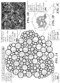
- first scaffolded mesoporous carbon-based material and the second scaffolded mesoporous carbon-based material can each further include a plurality of electrically conductive three-dimensional (3D) aggregates of graphene sheets.
- the aggregates can be sintered together to form an open porous scaffold configured to provide an electrical conduction along and across contact points of the graphene sheets.
- the open porous scaffold can include a 3D hierarchical structure with mesoscale structuring in combination with fractal-like structuring, wherein the fractal-like structuring is formed based at least in part on a mass or number of primary particles, or based at least in part on a micro, meso, or macro characteristic of a cluster size.
- the first scaffolded mesoporous carbon-based material and the second scaffolded mesoporous carbon-based material can include a porous arrangement formed in the open porous scaffold and configured to receive electrolyte dispersed therein for ion transport through interconnected pores that define one or more channels.
- each channel of the one or more channels includes: (1) a first portion that provides tunable ion conduits, (2) a second portion that facilitates rapid ion transport, and (3) a third portion that at least partially or temporarily confines active material.
- the point-of-use battery system comprising: an anode composed of non-toxic biocompatible metal comprising any one or more of Zn, Mg, or Al and configured to yield a cell voltage of approximately 1.5V-3V, a first printable carbon-based current collector comprising biocompatible multiple few layer graphene (FLG) sheets in electrical contact with the anode and extending therefrom, a 3D hierarchical mesoporous carbon-based cathode having an open porous structure for gas diffusion with areas to catalyze active material reduction comprising oxygen (O 2 ) and other gaseous species, the reduced oxygen creating water upon exposure to ambient air, the open porous structure for active water management.
- anode composed of non-toxic biocompatible metal comprising any one or more of Zn, Mg, or Al and configured to yield a cell voltage of approximately 1.5V-3V
- a first printable carbon-based current collector comprising biocompatible multiple few layer graphene (FLG) sheets in electrical contact with the anode and extending therefrom
- FLG biocompatible multiple
- a polymer-based barrier film is applied over the 3D hierarchical mesoporous carbon-based cathode to prevent oxygen and moisture from entering the open porous structure, the polymer-based barrier film being removable via the peel-back action to permit oxygen to enter the open porous structure.
- the foregoing point-of-use battery system further includes a second printable carbon-based current collector comprising biocompatible multiple few layer graphene (FLG) sheets in electrical contact with the cathode and extending therefrom, an electrolyte comprising a non-toxic biocompatible aqueous solution independent of organic solvents, the electrolyte activating to conduct ions upon any one or more of the following situations: when an applied pressure causes rupture of electrolyte containing polymeric microspheres such that the rupture releases electrolyte that infiltrates the open porous structure and the anode; or when a hygroscopic compound having solid salts contained within the anode is activated such that the hygroscopic compound extracts moisture to solubilize the solid salts.
- FLG multiple few layer graphene
- the foregoing point-of-use battery system further includes an ion-impregnated cellulose support structure wherein any one or more of the anode or the 3D hierarchical mesoporous carbon-based cathode is 3D printed on opposing sides thereof that activate upon exposure of the ion-impregnated cellulose support structure to O occurring upon the peel-back of the polymer-based barrier film.
- the point-of-use battery system can be configured such that the anode and the cathode each further include a 3D scaffolded mesoporous carbon-based material.
- the scaffolded mesoporous carbon-based material further can include a plurality of electrically conductive three-dimensional (3D) aggregates of graphene sheets, the aggregates forming an open porous scaffold that facilitates electrical conduction along contact points of the graphene sheets.
- 3D electrically conductive three-dimensional
- the point-of-use battery is activated by directly or indirectly applying pressure to the anode or by directly or indirectly applying pressure to the cathode, or by directly or indirectly applying pressure to both the anode and the cathode.
- the battery system can be fabricated by any one or more of 3D printing and/or additive manufacturing techniques.
- the anode and and/or the cathode are 3D printed onto any one or more of a flexible substrate, a semi-rigid substrate, or a rigid substrate, moreover in some situations, the substrate is formed by a portion of a shipping or mailing container.
- the shipping or mailing container may be formed of card stock, and/or cardboard, and/or paper, and/or polymer-coated paper.
- the flexible substrate, the semi-rigid substrate, or the rigid substrate can be produced as a label such as a shipping or mailing label.
- Another innovative aspect of the subject matter described in this disclosure can be implemented as a multi-part battery system configured to power a sensor having a sensing material with a chemistry additive for detecting an analyte.
- Some of such implementations include an anode; a cathode; and an electrolyte, wherein activation of the multi-part battery system to power the sensor is accomplished to release the electrolyte between the anode and the cathode in directed absence of thermal radiation. Once released, the electrolyte between the anode and the cathode establishes ionic transport there-between.
- the sensing material may include a particulate carbon.
- any one or more of the anode or the cathode are formed of electrically conductive three-dimensional (3D) aggregates of graphene sheets that form an open porous scaffold to facilitate electrical conduction along contact points of the graphene sheets.
- the porous arrangement in the open porous scaffold is conducive to receiving the electrolyte dispersed therein for ion transport through interconnected pores, thus providing power to an electrical circuit.
- the sensor is an impedance sensor that is tuned to respond to presence of an analyte such as nitroglycerine, sarin gas, mustard gas, or cyclone B.
- the sensor can trigger (such as by either directly or indirectly powering) a beacon if the analyte is any one or more of nitroglycerine, sarin gas, mustard gas, or cyclone B to at least partially assist in location of a container equipped with the multi-part battery system.
- one or more of the anode, the cathode, or the electrolyte are substantially non-toxic so as to at least partially assist in biodegradable disposal of the container.
- the foregoing multi-part battery system further can include: (1) a flexible substrate; (2) a resonant gas sensor circuit comprising a transducer arranged on the flexible substrate; (3) a sensing material disposed on the flexible substrate and electrically coupled to the transducer, wherein the sensing material includes carbon material in particulate form and a reactive chemistry additive; and (4) an alternating current (AC) source configured to supply AC signals to a first terminal of the transducer, the AC signals comprising a range of frequencies, any one or more of which stimulate the resonant gas sensor.
- AC alternating current
- Implementations further include a ground electrode electrically coupled to the transducer and non-ground terminal.
- the foregoing multi-part battery system can be configured such that the reactive chemistry additive reacts with the analyte to change electrical properties of the sensing material.
- the sensing material is interrogated by the gas sensor circuit to detect the change in electrical properties due to exposure of the sensing material to the analyte.
- a carbon material in particulate form is used to enhance sensitivity of the gas sensor circuit when detecting the analyte.
- Such a point-of-use battery system includes: (1) active electrode materials for both anode and cathode consisting of printable non-toxic biocompatible polymers, metal oxides/chlorides, metals, or carbon wherein the anode is composed of metal comprising any one or more of Zn, Mg, or Al; (2) a 3D hierarchical mesoporous carbon-based cathode having an open porous structure for gas or liquid ionic diffusion and having areas to catalyze active material reduction comprising oxygen (O 2 ) and water (H 2 O) that is actively managed from ambient air or from amounts of MnO 2 or AgO that is loaded onto a carbon host structure; and (3) a carbon cellulose nanofibril film that serves as a non-toxic, biocompatible/bioresorbable electrolyte and that serves as
- the electrolyte is an aqueous based electrolyte exhibiting a cell voltage of less than 1.5 Volts.
- the aqueous based electrolyte contains solid salts and hygroscopic agents. Further, the hygroscopic agents are composed of carbon so as to absorb water from ambient air for cell activation. Cell activation is contemporaneous with and/or is caused by solvation of buffered saline.
- the electrolyte is an organo-polymer based electrolyte having a cell voltage up to 4V.
- the polymer serves as a porous medium for retaining a pre-loaded ionic liquid therein.
- the polymer can serve to retain or absorb ionic liquid released from ruptured microspheres.
- Some implementations include an air cathode where a substrate serves as structure to provide electrolyte support for the point-of-use battery.
- the anode and cathode are disposed and/or aligned on opposing sides of the electrolyte support structure.
- battery activation can be accomplished by peeling back a thin film polymer barrier film that is disposed over the air cathode so as to expose the air cathode to oxygen and moisture.
- This and other implementations can further include: (1) a first printable carbon-based current collector comprising biocompatible multiple few layer graphene (FLG) sheets in electrical contact with the anode and extending therefrom; and/or (2) a polymer-based barrier film applied over the 3D hierarchical mesoporous carbon-based cathode to prevent O and moisture from entering the open porous structure, wherein the polymer-based barrier film is removable by a peel-back action to permit oxygen to enter the open porous structure; and/or (3) a second printable carbon-based current collector comprising biocompatible multiple few layer graphene (FLG) sheets in electrical contact with the cathode.
- a first printable carbon-based current collector comprising biocompatible multiple few layer graphene (FLG) sheets in electrical contact with the anode and extending therefrom
- FLG multiple few layer graphene
- FIGS. 1 A- 1 B show an exploded view of layers of a printed battery, such layers including elements of a cathode and anode portion, respectively.
- FIGS. 1 C 1 - 1 C 2 show folding techniques related to activating aspects of the printed battery shown in FIGS. 1 A- 1 B .
- FIGS. 1 D 1 - 1 D 3 discuss example printed battery features.
- FIG. 1 E shows a flowchart related to a method for activating an example printed battery.
- FIG. 2 shows an example schematic for a traditional Li ion battery incorporating the presently disclosed 3D self-assembled binder-less mesoporous carbon-based particles.
- FIGS. 3 A-F show illustrative schematic representations, at various magnification levels, and/or micrographs of a 3D self-assembled binder-less 3D mesoporous carbon-based particle having tunable electrical pathways and ionic conduits throughout the thickness thereof.
- FIG. 3 G shows a micrograph of an example enlarged section of the 3D self-assembled binder-less mesoporous carbon-based particle shown in at least FIGS. 1 A- 1 E .
- FIG. 3 H shows an illustrative schematic representation of a multi-layered carbon-based scaffolded structure, each layer comprising various concentrations of the 3D mesoporous carbon-based particles shown in FIGS. 1 A-F , deposited on an electrically conductive substrate.
- FIG. 4 A shows an illustrative schematic representation of a multi-layered carbon-based scaffolded structure, each layer comprising various concentrations of any one or more of the 3D mesoporous carbon-based particles shown herein, deposited on an electrically conductive substrate, the multi-layered carbon-based scaffolded structure having lithium metal infused into nanoscale gaps therein.
- FIG. 4 B shows an illustrative schematic representation of a series of plasma spray torches oriented in a substantially continuous sequence above a roll-to-roll (R2R) processing apparatus, where the plasma spray torches are configured to grow the 3D mesoporous carbon-based particles in an incremental layer-by-layer manner.
- R2R roll-to-roll
- FIGS. 5 A-B show various photographs and/or micrographs related of example variants of the 3D mesoporous carbon-based particles shown herein.
- FIGS. 5 C 1 - 5 C 3 show examples related to a printed battery featuring pressure-based electrolyte release capabilities.
- FIGS. 5 C 4 - 5 C 5 shows an example of metal-air battery chemistry including an air (cathode) electrode reaction and a metal (anode) electrode reaction.
- FIG. 6 A- 6 C shows views of a printed battery that can be activated at a point-of-use.
- FIGS. 7 A- 8 A show self-aligning geometry that self-aligns even in presence of lateral misregistration.
- FIG. 8 B shows an example listing of printed battery properties and advantages.
- FIG. 9 illustrates a configuration of an anode and cathode interdigitated therewith, both the anode and cathode being disposed on a component layer, which is disposed on a substrate layer.
- FIG. 10 an exploded view of layers of an example printed battery, such layers including elements of a cathode and anode portion, respectively.
- FIG. 11 an exploded view of layers of an example printed battery, such layers including elements of a cathode and anode portion, respectively.
- FIGS. 12 A-B show an example where printed batteries are activated by an external source.
- FIGS. 12 C- 18 show information, targets, properties, and related materials for printed batteries according to a variety of examples of the presently disclosed implementations.
- FIGS. 19 A and 19 B show scanning electron microscope (SEM) images from particulate carbon containing graphene, in accordance with some implementations.
- FIGS. 20 A and 20 B show transmission electron microscope (TEM) images from particulate carbon containing graphene, in accordance with some implementations.
- TEM transmission electron microscope
- FIG. 21 is a plan view schematic of an electrochemical gas sensor, in accordance with some implementations.
- FIG. 22 is a table that lists examples of possible redox mediators that may be used, in accordance with some implementations.
- FIG. 23 shows an example of an electrochemical sensor where a first electrode and a second electrode are configured as interdigitated fingers, in accordance with some implementations.
- FIG. 24 shows an example of a chemical sensor in which high frequency spectroscopy is used as the detection method, in accordance with some implementations.
- FIG. 25 A shows a non-limiting example of a resonant gas sensor inside view and plan view, in accordance with some implementations.
- FIG. 25 B shows an example of a response from a resonant gas sensor in the presence of an analyte of interest, in accordance with some implementations.
- FIGS. 25 C and 25 D show non-limiting examples of resonant gas sensors inside view and plan view, in accordance with some implementations.
- FIG. 25 E shows a non-limiting example of a resonant gas sensor with a sensing material containing particulate carbon, in accordance with some implementations.
- FIG. 25 F shows a non-limiting example of a resonant gas sensor inside view and plan view, in accordance with some implementations.
- FIGS. 26 A- 26 C show a time evolution of example spectra produced when an analyte is detected by a resonant gas sensor, in accordance with some implementations.
- FIG. 27 shows a non-limiting example of a chemiluminescent gas sensor, in accordance with some implementations.
- FIG. 28 shows a non-limiting example of a sensor system in which multiple individual chemical sensors are used for detecting an analyte, in accordance with some implementations.
- Li-ion battery is a type of secondary (rechargeable) battery.
- Li-ion battery technology has become very important in recent years as these batteries show great promise as power sources that can lead to an electric vehicle (EV) revolution (referring to widespread implementation of EVs across numerous applications).
- EV electric vehicle
- the development of new materials (for Li-ion batteries) is the focus of research in the field of materials science, as Li-ion batteries can be considered to be the most impressive success story of modern electrochemistry.
- Li-ion batteries power most modern portable devices and seem to have overcome psychological barriers of the consuming public against the use of such high energy density devices on a larger scale for more demanding applications, such as EV.
- Li-ion batteries Li ions (Li+) migrate from the negative electrode through an electrolyte to the positive electrode during discharge and return when charging.
- Li-ion batteries traditionally use an intercalated Li compound as a formative material at the positive electrode and graphite at the negative electrode.
- the batteries have a high energy density, no “memory-effect” (describing the situation in which nickel-cadmium batteries gradually lose their maximum energy capacity if they are repeatedly recharged after being only partially discharged) and low self-discharge.
- Li ion batteries can (due to the highly reactive nature of elemental and ionic Li) present a safety hazard.
- Li ion batteries can contain a flammable electrolyte, if they are punctured, hit, otherwise damaged or even incorrectly (excessively) charged, Li batteries can deteriorate unexpectedly, including through explosions and fires. Nevertheless, the high energy density of Li ion batteries permits for longer usable lifespans of several hours between charging cycles, and longer cycle life, referring to the electric current delivery or output performance of a given Li-ion battery over multiple repeat charge-discharge (partial or total charge depletion) cycles.
- Li metal due to its high theoretical specific capacity of 3,860 mAh/g, low density (0.59 g cm ⁇ 3) and low negative electrochemical potential ( ⁇ 3.040 V compared to a standard hydrogen electrode), appears as an ideal material for the negative electrode of secondary Li-ion batteries.
- unavoidable and uncontrollable dendrite growth referring the growth of a branching tree-like structure within the battery itself, caused by Li precipitates can cause serious safety concerns related to short-circuits, and limited Coulombic efficiency, referring to the charge efficiency by which electrons are transferred in batteries, during deposition and stripping operations inherent in Li-ion batteries.
- Such challenges have previously impeded Li ion battery applications.
- Li-ion batteries typically feature carbonaceous materials used as an anode, such carbonaceous anode materials including: (1) graphite; (2) amorphous carbon; and, (3) graphitized carbon.
- the first type of the three carbonaceous materials presented above includes naturally occurring graphite and synthetic graphite (or artificial graphite, such as Highly Oriented Pyrolytic Graphite, HOPG). Either form of graphite can be intercalated with Li.
- the resulting Graphite Intercalation Compound (GIC) may be expressed as Li x C 6 , where X is typically less than 1. To limit (minimize) the loss in energy density due to the replacement of Li metal with the GIC, X in Li x C 6 must be maximized and the irreversible capacity loss (Q ir ), in the first charge of the battery must be minimized.
- Carbon-based anodes such as (1) graphite intercalated with Li as discussed above, can demonstrate extended cycle lifespans due to the presence of a surface-electrolyte interface layer (SEI), which results from the reaction between Li and surrounding electrolyte (or between Li and the anode surface/edge atoms or functional groups) during the initial several charge-discharge cycles.
- SEI surface-electrolyte interface layer
- Li ions consumed in this reaction may be derived from some of the Li ions originally intended for the charge transfer purpose (referring to the dissociation of elemental Li when intercalated with carbon in a carbon-based structure, such as the anode, during Li ion movement in electrolyte across a porous separator to the cathode as related to electron release and flow to power a load during Li ion battery discharge cycles.
- the Li ions become part of the inert SEI layer and become “irreversible”, in that they can no longer be an active element (or ion) used for charge transfer.
- Q ir has been attributed to graphite exfoliation caused by electrolyte/solvent co-intercalation and other side reactions.
- amorphous carbon contains no (or very little) micro- or nano-crystallites.
- Amorphous carbon includes both so-called “soft carbon” and “hard carbon”. Soft carbon refers to a carbon material that can be graphitized at a temperature of about 2,500° C. or higher. In contrast, hard carbon refers to a carbon material that cannot be graphitized at a temperature higher than 2,500° C.
- amorphous carbons commonly used as anode active materials may not be purely amorphous, but rather contain some minute amount of micro- or nano-crystallites, each crystallite being defined as a small number of graphene sheets (oriented as basal planes) that are stacked and bonded together by weak van der Waals forces.
- the number of graphene sheets can vary between one and several hundreds, giving rise to a c-directional dimension (thickness L e ) of typically 0.34 nm to 100 nm.
- the length or width (La) of these crystallites is typically between tens of nanometers to microns.
- soft and hard carbons can be produced by low-temperature pyrolysis (550-1,000° C.) and exhibit a reversible specific capacity of 400-800 mAh/g in the 0-2.5 V range.
- a so-called “house-of-cards” carbonaceous material has been produced with enhanced specific capacities approaching 700 mAh/g.
- Li ion battery variants may vary across Li ion battery variants.
- Handheld electronics may use Li polymer batteries (with a polymer gel as electrolyte) with Li cobalt oxide (LiCoO 2 ) as cathode material, which offers high energy density but may present safety risks, especially when damaged.
- Li iron phosphate (LiFePO 4 ), Li ion manganese oxide battery (LiMn 2 O 4 , Li 2 MnO 3 , or LMO), and Li nickel manganese cobalt oxide (LiNiMnCoO 2 or NMC) may offer lower energy density but provide longer useful lives and less likelihood of fire or explosion.
- Such batteries are widely used for electric tools, medical equipment, and other roles. NMC in particular is often considered for automotive applications.
- High conductance carbon materials such as carbon nanotubes (CNT), graphene, amorphous carbon, and/or crystalline graphite in electronics allows for the printing of these materials onto many types of surfaces without necessarily using printed circuit boards, and/or without the use of materials or compounds that have been identified as being toxic to humans.
- Usage of high conductance carbon as a feedstock material and/or other material during any one or more of the additive manufacturing processes described above may facilitate the fabrication of batteries (including Li ion batteries) with micro-lattice structures suitable for enhanced functionality, electric power storage and delivery, and optimal efficiency.
- Printing technologies using high conductance carbon materials such as carbon nanotubes (CNT), graphene, amorphous carbon, or crystalline graphite may be implemented and/or otherwise incorporated in the fabrication of the following devices: antennas (tuned antennas), sensors (bio sensors), energy harvesters (photocells), and other electronic devices.
- CNT carbon nanotubes
- amorphous carbon amorphous carbon
- crystalline graphite amorphous graphite
- Graphene is an allotrope of carbon in the form of a single layer of atoms in a two-dimensional hexagonal lattice in which one atom forms each vertex. It is the basic structural element of other allotropes, including graphite, charcoal, carbon nanotubes and fullerenes. It can also be considered as an indefinitely large aromatic molecule, the ultimate case of the family of flat polycyclic aromatic hydrocarbons.
- Graphene has a special set of properties which set it apart from other elements. In proportion to its thickness, it is about 100 times stronger than the strongest steel. Yet its density is dramatically lower than any other steel, with a surfacic (surface-related) mass of 0.763 mg per square meter. It conducts heat and electricity very efficiently and is nearly transparent. Graphene also shows a large and nonlinear diamagnetism, even greater than graphite and can be levitated by Nd—Fe—B magnets. researchers have identified the bipolar transistor effect, ballistic transport of charges and large quantum oscillations in the material.
- Functionalization implies the process of adding new functions, features, capabilities, or properties to a material or substance by altering the surface chemistry of the material. Functionalization is a fundamental technique used throughout chemistry, materials science, biological engineering, textile engineering, and nanotechnology and may be performed by attaching molecules or nanoparticles to the surface of a material, with a chemical bond or through adsorption, the adhesion of atoms, ions or molecules from a gas, liquid or dissolved solid to a surface to create a film of the adsorbate on the surface of the adsorbent without forming a covalent or ionic bond thereto.
- Functionalization and dispersion of graphene sheets may be of critical importance to their respective end-use applications.
- Chemical functionalization of graphene enables the material to be processed by solvent-assisted techniques, such as layer-by-layer assembly, spin-coating, and filtration and also prevents the agglomeration of single layer graphene (SLG) during reduction and maintains the inherent properties of graphene.
- solvent-assisted techniques such as layer-by-layer assembly, spin-coating, and filtration and also prevents the agglomeration of single layer graphene (SLG) during reduction and maintains the inherent properties of graphene.
- SSG single layer graphene
- the functionalization of graphene may be performed by covalent and noncovalent modification techniques.
- surface modification of graphene oxide followed by reduction has been carried out to obtain functionalized graphene. It has been found that both the covalent and noncovalent modification techniques are very effective in the preparation of processable graphene.
- Graphite as commonly understood and as referred to herein, implies a crystalline form of elemental carbon with atoms arranged in a hexagonal structure. Graphite occurs naturally in this form and is the most stable form of carbon under standard (atmospheric) conditions. Otherwise, under high pressures and temperatures, graphite converts to diamond. Graphite is used in pencils and lubricants. Its high conductivity makes it useful in electronic products such as electrodes, batteries, and solar panels.
- R2R processing refers to the process of creating electronic devices on a roll of flexible plastic or metal foil.
- R2R processing may also refer to any process of applying coatings, printing, or performing other processes starting with a roll of a flexible material and re-reeling after the process to create an output roll. These processes, and others such as sheeting, may be grouped together under the general term “converting”. When the rolls of material have been coated, laminated or printed they can be subsequently cut and/or slit to their finished size on a slitter rewinder.
- R2R processing of large-area electronic devices may reduce manufacturing cost.
- Other applications could arise which take advantage of the flexible nature of the substrates, such as electronics embedded into clothing, 3D-printed Li ion batteries, large-area flexible displays, and roll-up portable displays.
- 3D printing or Additive Manufacturing has found applications in various manufacturing, medical, industry and sociocultural sectors, which in turn have generated enough interest to further facilitate research and development. Also, 3D printing has been used in humanitarian applications to produce a range of medical items, including prosthetics, spares, and repairs.
- Additive manufacturing techniques are adaptable and may be configured for a nearly innumerable amount of end-use applications, including, by way of example, but not limitation thereto, food, such as by squeezing out food, layer by layer, into three-dimensional objects.
- food such as by squeezing out food, layer by layer, into three-dimensional objects.
- a large variety of foods may be appropriate candidates, such as chocolate and candy, and flat foods such as crackers, pasta, and pizza.
- sources indicate that NASA is looking into the technology in order to create 3D printed food to limit food waste and to make food that are designed to fit an astronaut's dietary needs.
- 3D printing has also entered clothing, with fashion designers experimenting with 3D-printed shoes and dresses.
- Nike® is using 3D printing to prototype and manufacture the 2012 Vapor Laser Talon football shoe for players of American football
- New Balance is 3D manufacturing custom-fit shoes for athletes.
- 3D printing has even progressed to a level where companies are printing consumer-grade eyewear with on-demand custom fit and styling (although they cannot print the lenses). On-demand customization of glasses is possible with rapid prototyping.
- Lithium-ion battery capacity may be significantly improved upon, at a microscale level, if such batteries are produced with electrodes that have pores and channels. And, although previously often used, an interdigitated geometry allows for lithium to transport through the battery efficiently during charging and discharging, but may not always be optimal depending on intended end-uses, etc.
- electrodes with porous architectures can lead to higher charge capacities since such architectures or configurations allow lithium to penetrate through the electrode volume leading to very high electrode utilization, and thus higher energy storage capacity.
- battery electrodes manufactured by 3D printing create a microlattice electrode architecture that allows for the efficient transport of lithium through the entire electrode, which also increases battery charging rates.
- 3D-printed microlattice structures used as electrodes in lithium-ion batteries have been shown to improve battery performance in several ways, including, but not limited to: a fourfold increase in specific capacity and a twofold increase in areal capacity when compared to a solid block electrode, such as may be related to surface area to volume ratios of such 3D printed microlattice structures. Further, 3D printed electrodes have been shown to retain their complex 3D lattice structures after many, such as forty, electrochemical cycles thus demonstrating their mechanical robustness and ongoing reliability.
- such 3D printed batteries with specific microstructures can have relatively high electrical charge storage capacity for the same weight or alternately, for the same capacity, a greatly reduced weight, such as by offering optimal surface area to volume ratios and configurations, which may be an important attribute for certain applications requiring enumerated parameters, such as transportation and medical device applications, including implantable devices beneath the skin.
- Non-biological electronic micro-devices may also benefit from developments in 3D printing of battery microstructures.
- electronic devices, small drones, and aerospace applications themselves may also benefit from and use 3D printing technology as well, due to the low weight and high capacity of the batteries printed using this method.
- Redox are a type of chemical reaction in which the oxidation states of atoms are changed. Redox reactions are characterized by the transfer of electrons between chemical species, most often with one species, such as the reducing agent, undergoing oxidation, losing electrons, while another species, the oxidizing agent, undergoes reduction, gains electrons. The chemical species from which the electron is stripped is said to have been oxidized, while the chemical species to which the electron is added is said to have been reduced.
- intercalation is the reversible inclusion or insertion of a molecule (or ion) into materials with layered structures. Examples are found in graphite, graphene, and transition metal dichalcogenides.
- Electrochemical Capacitors ECs
- Electrochemical capacitors also referred to as “ultracapacitors” and/or “supercapacitors”, are considered for uses in hybrid or full EVs.
- ECs can supplement (or in certain uses replace) traditional batteries, including high-performance Li ion batteries, used in an EVs to provide short bursts of power (forward propulsion) often needed for rapid acceleration.
- Traditional batteries may still be used provide uniform power for cruising at normal highway speeds, but supercapacitors (with their ability to release energy much more quickly than batteries) may activate and supplement battery-provided power at times when the car needs to accelerate, such as for merging, passing, emergency maneuvers, and hill climbing.
- ECs must also store sufficient energy to provide an acceptable driving range, such as from 220-325 miles or more. And, to be cost- and weight-effective compared to additional battery capacity, ECs must combine adequate specific energy and specific power with long cycle life and meet cost targets as well. Specifically, ECs for application in EVs must store about 400 Wh of energy, be able to deliver about 40 kW of power for about 10 seconds and provide high cycle-life (>100,000 cycles).
- the high volumetric capacitance density of an EC derives from using porous electrodes, which may incorporate, feature, and/or be constructed from scaffolded graphene-based materials, to create a large effective “plate area” and from storing energy in the diffuse double layer.
- This double layer created naturally at a solid-electrolyte interface when voltage is imposed, has a thickness of only about 1-2 nm, therefore forming an extremely small effective “plate separation.”
- stored energy is further augmented by pseudo-capacitance effects, occurring again at the solid-electrolyte interface due to electrochemical phenomena such as the redox charge transfer.
- the double layer capacitor is based on a high surface area electrode material, such as activated carbon, immersed in an electrolyte. A polarized double layer is formed at electrode-electrolyte interfaces providing high capacitance.
- Electrochemical Li intercalation or de-intercalation properties of carbon and carbon-based materials depend significantly on their respective morphology, crystallinity, orientation of crystallites, and defects as well. Further, the electric storage capacity of a Li-ion battery can be enhanced by the selection and integration of desirable nano-structured carbon materials such as carbon in certain allotropes such as graphite and graphene, or nano-sized graphite, nanofibers, isolated single walled carbon nanotubes, nano-balls, and nano-sized amorphous carbon, having small carbon nanostructures in which no dimension is greater than about 2 m.
- known methods for fabricating carbon and Li-ion electrodes for rechargeable Li cells include steps for forming a carbon electrode composed of graphitic carbon particles adhered by an ethylene propylene diene monomer binder used to achieve a carbon electrode capable of subsequent intercalation by Li-ions.
- the carbon electrode is reacted with Li-ions to incorporate Li-ions into graphitic carbon particles of the electrode.
- An electrical current is repeatedly applied to the carbon electrode to initially cause a surface reaction between the Li-ions and to the carbon and subsequently cause intercalation of the Li-ions into crystalline layers of the graphitic carbon particles. With repeated application of the electrical current, intercalation is achieved to near a theoretical maximum.
- exfoliated graphite-based hybrid material compositions relate to: (a) micron- or nanometer-scaled particles or coating which are capable of absorbing and desorbing alkali or alkaline metal ions (particularly, Li ions); and, (b) exfoliated graphite flakes that are substantially interconnected to form a porous, conductive graphite network comprising pores.
- the particles or coating resides in a pore of the network or is attached to a flake of the network.
- the exfoliated graphite amount is in the range of 5% to 90% by weight and the number of particles or amount of coating is in the range of 95% to 10% by weight.
- silicon-based anode active materials have been shown to be effective in combination with high capacity Li rich cathode active materials.
- Supplemental Li is shown to improve the cycling performance and reduce irreversible capacity loss for some silicon based active materials.
- Silicon based active materials can be formed in composites with electrically conductive coatings, such as pyrolytic carbon coatings or metal coatings, and composites can also be formed with other electrically conductive carbon components, such as carbon nano fibers and carbon nanoparticles.
- the carbonaceous electrode may include a multi-phase composition including both highly graphitized and less graphitized phases or may include a single phase, highly graphitized composition subjected to intercalation of Li at above about 50° C. Incorporation of an electrically conductive filamentary material such as carbon black intimately interspersed with the carbonaceous composition minimizes capacity loss upon re-peated cycling.
- a known Li based negative electrode material is characterized by comprising 1 m 2 /g or more of carbonaceous negative electrode active material specific surface area, a styrene-butadiene rubber binder, and a fiber diameter formed to 1,000 nanometers of carbon fiber.
- Such negative electrode materials are used for Li batteries, which have desirable characteristics, such as a low electrode resistance, high strength of the electrode, an electrolytic solution having excellent permeability, high energy density and a high rate charge/discharge.
- the negative electrode material contains 0.05 to 20 mass % of carbon fibers and a styrene at 0.1 to 6.0% by mass.
- Butadiene rubber forms the binder and may further contain 0.3 to 3% by mass thickener, such as carboxymethyl methylcellulose.
- anode active material that has been: (1) pre-lithiated; and, (2) pre-pulverized.
- This anode may be prepared with a method that comprises: (a) providing an anode active material; (b) intercalating or absorbing a desired amount of Li into the anode active material to produce a pre-lithiated anode active material; (c) comminuting, referring to the reduction of solid materials from one average particle size to a smaller average particle size, by crushing, grinding, cutting, vibrating, or other processes, the pre-lithiated anode active material into fine particles with an average size less than 10 ⁇ m (preferably ⁇ 1 ⁇ m and most preferably ⁇ 200 nm); and, (d) combining multiple fine particles of the pre-lithiated anode active material with a conductive additive and/or a binder material to form the anode.
- the pre-lithiated particles are protected by a Li ion-conducting matrix or coating material.
- Graphitic nanofibers have also been disclosed and include tubular fullerenes (commonly called “buckytubes”), nano tubes and fibrils, which are functionalized by chemical substitution, are used as electrodes in electrochemical capacitors.
- the graphitic nanofiber-based electrode increases the performance of the electrochemical capacitors.
- Preferred nanofibers have a surface area greater than about 200 m 2 /gm and are substantially free of micropores.
- known high surface area carbon nanofibers have an outer surface on which a porous high surface area layer is formed.
- Methods of making the high surface area carbon nanofiber include pyrolizing a polymeric coating substance provided on the outer surface of the carbon nanofiber at a temperature below the temperature at which the polymeric coating substance melts.
- the polymeric coating substance used as the high surface area around the carbon nanofiber may include phenolics such as formaldehyde, polyacrylonitrile, styrene, divinyl benzene, cellulosic polymers and cyclotrimerized diethynyl benzene.
- the high surface area polymer which covers the carbon nanofiber may be functionalized with one or more functional groups.
- FIGS. 1 A- 1 B show an exploded view of layers of a printed battery, such layers including elements of a cathode and anode portion, respectively.
- a stacked (such as “sandwiched”) architecture of a battery 100 B (shown implemented in package 300 A) as shown here includes elements of a cathode portion and an anode portion.
- the cathode portion may include an electrolyte layer 140 B and a cathode 106 B in a vertically stacked and adjacent configuration shown adhered to substrate 108 B by seal 107 B.
- anode portion 110 B may also include substrate 101 B adhered to anode 104 B via seal 103 B.
- Each the anode and cathode portions may include collectors 102 B, 109 B that are 3D printed substrates 101 B, 108 B, respectively.
- electrolyte layer 105 B is shown as being included on the cathode portion, although in other implementations the electrolyte may be incorporated within the cathode 106 B.
- Each electrode, such as anode 104 B and cathode 106 B, is shown in FIGS. 1 A- 1 B as being a layer positioned between current collectors 102 B, 109 B, respectively and the electrolyte layer 105 B.
- Seals 103 B, 107 B can define perimeters (to be described in further detail below) that constrain spreading of electrolyte 105 B and/or electrode materials when the battery is activated.
- Printed substrate surrounding battery 100 B may serve as seals 103 B, 107 B, while in other implementations seals 303 B, 107 B may be formed from another substance deposited onto the substrate.
- FIGS. 1 C 1 - 1 C 2 show folding techniques related to activating aspects of the printed battery shown in FIGS. 1 A- 1 B .
- FIGS. 1 D 1 - 1 D 3 discuss example printed battery features.
- FIG. 1 E shows a flowchart related to a method for activating an example printed battery.
- FIG. 2 shows an example schematic for a traditional Li ion battery incorporating the presently disclosed 3D self-assembled binder-less mesoporous carbon-based particles.
- An example Li ion secondary electrochemical cell (battery) system 200 is shown in FIG. 2 , having an anode 203 and cathode 202 separated by separator 217 , all at least partially contained and/or exposed to (Li) ion-conducting electrolyte solution 238 (containing dissociated lithium ion conducting salt 202 ) as shown.
- the separator a porous membrane to electrically isolate the two electrodes from each other, is also in the position showed.
- Single lithium ions migrate through pathway 207 back and forth between the electrodes of the lithium ion-battery during charging and discharging and are intercalated into the active materials.
- the active materials of the positive electrode are, for example, mixed oxides. Those of the negative electrode mainly are graphite and amorphous carbon compounds.
- the positive electrode contains active materials such as mixed oxides.
- the active materials of the negative electrode mainly are graphite and amorphous carbon compounds. These are the materials into which the lithium is intercalated.
- lithium ion conducting salt 202 (also referring to Li ions generally) can intercalate into any one or more of the unique carbon-based structures (referring the mesoporous carbon-based particle 300 A, 300 E, carbon-scaffold 300 H, and lithiated carbon-scaffold 400 A and/or the like employed as an anode 203 , replacing traditional anode 203 , and/or a cathode 204 , replacing traditional cathode 202 ) all of which are proprietary to LytEn, Inc., of Sunnyvale, Calif., to achieve surprising and wholly unexpected specific capacity retention capability far in excess of the 372 mAh/g values commonly cited in traditional Li ion battery related technologies, inclusive of performance at a level 3x or greater (referring to specific capacity retention capabilities exceeding 3,300 mAh/g or more), all made possible through the unique, multi-modal, hierarchical pores 303 A and/or 307 F defined by open porous scaffold 302 A of mesoporous carbon-based particle 300
- Li ions form complexes and/or compounds with S, for example, and are temporarily retained during charge-discharge cycles at levels not otherwise achievable through conventional unorganized carbon structures requiring adhesive definition and combination via a binder, which can (as discussed earlier) also inhibit overall battery performance and longevity.
- lithium metal 234 micro-confined within hierarchical mesoporous carbon-based anode 203 (and in between graphene sheets 232 associated therewith as shown in area 233 ) may dissociate pursuant to the following equation (3): FLG-Li ⁇ FLG+Li+ e ⁇ (1)
- Eq. (3) shows electrons 233 discharging 208 to power an external load and lithium ions 232 migrating to cathode 202 and/or hierarchical mesoporous carbon-based cathode 204 to return to a thermodynamically favored position within a cobalt oxide-based lattice pursuant to the following equation (2): x Li + +xe ⁇ +Li 3 ⁇ x CoO 2 ⁇ LiCoO 2 . (2) During charging, this process is reversed, where lithium ions 202 migrate from the positive electrode through the electrolyte and the separator to the negative electrode.
- Disclosed carbon-based structures (referring to the surprising favorable specific capacity values made possible by the unique multi-modal hierarchical structures of mesoporous carbon-based particle 300 A, 300 E and/or derivatives thereof, including carbon scaffold 300 H and lithiated carbon scaffold 400 A) build upon traditional advantages offered by lithium ion technology. Compared to sodium or potassium ions, the small lithium ion exhibits a significantly quicker kinetics in the different oxidic cathode materials. Another difference: as opposed to other alkaline metals, lithium ions can intercalate and deintercalate reversibly in graphite and silicon. Furthermore, a lithiated graphite electrode enables very high cell voltages.
- Disclosed carbon-based structures uniquely and unexpectedly enhance the ease through which lithium ions can intercalate and deintercalate reversibly between graphene sheets, due to the unique lay-out of few-layer graphene (FLG) (2-32 layers of graphene in a generally horizontally stacked configuration) 303 C as employed in mesoporous carbon-based particle 300 A and/or the like, and are suitable for application in traditional cylindrical (hardcase), pouch cell (softpack), and prismatic (hardcase) applications.
- FLG few-layer graphene
- FIGS. 3 A-H show illustrative schematic representations, at various magnification levels, and/or micrographs of a 3D self-assembled binder-less 3D mesoporous carbon-based particle having tunable electrical pathways and ionic conduits throughout the thickness thereof.
- FIG. 3 A shows a three-dimensional (3D) self-assembled binder-less multi-modal mesoporous carbon-based particle 300 A having controllable electrical and ionic conducting gradients distributed throughout, within which various aspects of the subject matter disclosed herein may be implemented.
- a mesoporous material as generally understood and as referred to herein, implies a material containing pores with diameters between 2 and 50 nm, according to IUPAC nomenclature
- IUPAC defines microporous material as a material having pores smaller than 2 nm in diameter and macroporous material as a material having pores larger than 50 nm in diameter.
- Mesoporous materials may include various types of silica and alumina that have similarly sized mesopores.
- Mesoporous oxides of niobium, tantalum, titanium, zirconium, cerium and tin have been researched and reported.
- mesoporous carbon has achieved particular prominence, having direct applications in energy storage devices.
- Mesoporous carbon is defined as having porosity within the mesopore range, and this significantly increases the specific surface area.
- Another common mesoporous material is “activated carbon”, referring to a form of carbon processed to have small, low-volume pores that increase the surface area.
- Activated carbon in a mesoporous context, is typically composed of a carbon framework with both mesoporosity and microporosity (depending on the conditions under which it was synthesized).
- a mesoporous material can be disordered or ordered in a mesostructure.
- mesoporous structure noticeably limits the number of lattice units, and this significantly changes the solid-state chemistry.
- the battery performance of mesoporous electroactive materials is significantly different from that of their bulk structure.
- Mesoporous carbon-based particle 300 A is nucleated and grown in an atmospheric plasma-based vapor flow stream of reagent gaseous species, which may include methane (CH 4 ), to form an initial carbon-containing and/or carbon-based particle. That initial particle may be expanded upon either:
- mesoporous carbon-based particle 300 A within a reaction chamber in and/or otherwise associated with a microwave-based reactor, such as a reactor disclosed by Stowell, et al., “Microwave Chemical Processing Reactor”, U.S. Pat. No. 9,767,992, (Sep. 19, 2017), incorporated by reference herein in its entirety, or thermal reactor, referring generally to a chemical reactor defined by an enclosed volume in which a temperature-dependent chemical reactor occurs.
- Mesoporous carbon-based particle 300 A (also mesoporous carbon-based particle 300 E as shown in FIG. 1 E ) is synthesized with a three-dimensional (3D) hierarchical structure comprising short range, local nano-structuring in combination with long range approximate fractal feature structuring, which in this context refers to the formation of successive layers involving the 90-degree rotation of each successive layer relative to the one beneath it, and so on and so forth, allowing for the creation of vertical (or substantially vertical) layers and/or intermediate (“inter”) layers.
- 3D three-dimensional
- the plurality of hierarchical (and/or contiguous) pores 307 F at least in part further define open porous scaffold 302 A with one or more Li ion diffusion pathways 309 F (as shown in FIG. 1 F ) having:
- Li ion diffusion pathways 309 F and/or hierarchical porous network 100 F more generally may act as or otherwise provide active Li intercalating structures, which may provide a source for specific capacity of an anode or cathode Li ion battery electrode at between about 744 mAh/g to about 1,116 mAh/g.
- Li may infiltrate open porous scaffold to at least partially chemically react with exposed carbon therein.
- Mesoporous carbon-based particle 300 A may be synthesized at least in part by a vapor flow stream of gaseous reagents including any one or more of a saturated or unsaturated hydrocarbon, such as methane (CH 4 ), flowed onto a substrate in a reactor, such as a microwave-based reactor and/or a thermal reactor.
- a saturated or unsaturated hydrocarbon such as methane (CH 4 )
- One or more physical, electrical, chemical and/or material properties of the mesoporous carbon-based particle 300 A may be defined during its synthesis.
- dopants referring to traces of impurity element that is introduced into a chemical material to alter its original electrical or optical properties, such as Si, SiO, SiO 2 , Ti, TiO, Sn, Zn, and/or the like
- material properties including: electrical conductivity, wettability, and/or ion conduction or transport through hierarchical porous network 100 F.
- Microporous textures having dimension 103 F and/or hierarchical porous network 100 F more generally may be synthesized, prepared or otherwise created to also (or otherwise) include smaller pores for chemical micro-confinement, the smaller pores being defined as ranging from 1 to 3 nm. Also, each graphene sheet (as shown in FIG. 1 C ) may range from 50 to 200 nm in diameter (La).
- Hierarchical porous network 100 F may be a further magnified and/or detailed variant of open porous scaffold 302 A, may provide one or more active Li intercalating structures, to be further described in structure and/or functionality in connection with FIGS. 6 - 19 C , which show various topic diagrams, flowcharts, schematics, photographs and/or micrographs related to lithium, lithium ion, sulfide, and/or lithium, sulfur and/or other element derived chemical substances and/or compounds infiltrated and/or infused into the multi-layered carbon-based scaffolded structure shown in FIG. 4 B .
- Open porous scaffold 302 A may be created independent of a binder, such as a traditional, nonconductive polymer binder typically used in conjunction with and a conductive additive onto a metal foil current collector in battery end-use applications.
- a binder such as a traditional, nonconductive polymer binder typically used in conjunction with and a conductive additive onto a metal foil current collector in battery end-use applications.
- Traditional configurations involving usage of a binder can lead to electronic/current conduction-related or ionic constrictions and poor contacts due to randomly distributed conductive phases.
- high-capacity electrode materials are employed, relatively high physical stress generated during electrochemical reactions can disrupt mechanical integrity of traditional binder systems, therefore, in turn, reducing cycle life of batteries.
- a vapor flow stream used to synthesize mesoporous carbon-based particle 300 A may be at least flowed in part into a vicinity of a plasma, such as that generated and/or flowed into a reactor and/or chemical reaction vessel.
- a plasma reactor may be configured to propagate microwave energy toward the vapor flow stream to at least in part assist with synthesis of mesoporous carbon-based particle 300 A, may involve carbon-particle based and/or derived nucleation and growth from constituent carbon-based gaseous species, such as methane (CH 4 ), where such nucleation and growth may substantially occur from an initially formed seed particle within a reactor. More particularly, such a reactor accommodates control of gas-solid reactions under non-equilibrium conditions, where the gas-solid reactions may be controlled at least in part by any one or more of:
- a vapor flow stream including carbon-containing constituent species, such as methane (CH 4 ) may be flowed into one of two general reactor types:
- An example microwave processing reactor used to synthesize mesoporous carbon-based particle 300 A may include microwave-generating energy source and a field-enhancing waveguide.
- the field-enhancing waveguide has a field-enhancing zone between a first cross-sectional area and a second cross-sectional area of the waveguide, and also has a plasma zone and a reaction zone.
- the second cross-sectional area is smaller than the first cross-sectional area, is farther away from the microwave energy source than the first cross-sectional area and extends along a reaction length of the field-enhancing waveguide.
- the supply gas inlet is upstream of the reaction zone. In the reaction zone, a majority of the supply gas flow is parallel to the direction of the microwave energy propagation.
- the supply gas is used to generate a plasma in the plasma zone to convert a process input material into separated components in the reaction zone at a pressure of at least 0.1 atmosphere, with a preference for 1 atmosphere where the surprising favorable physical properties of mesoporous carbon-based particle 300 A, as discussed above, were discovered.
- Propagation of microwave energy toward the carbon-containing or carbon-based vapor flow stream at least in part assists with synthesis of mesoporous carbon-based particle 300 A and facilitates carbon-particle nucleation and growth within a reactor.
- in-flight implies a novel method of chemical synthesis based on contacting particulate material derived from inflowing carbon-containing gaseous species, such as those containing methane (CH 4 ), to “crack” such gaseous species.
- Cracking implies the technical process of methane pyrolysis to yield elemental carbon, such as high-quality carbon black, and hydrogen gas, without the problematic contamination by carbon monoxide, and with virtually no carbon dioxide emissions.
- a basic endothermic reaction that may occur within a microwave reactor is shown as equation (1) below: CH 4 +74.85 kJ/mol ⁇ C+2H 2 (1)
- Carbon derived from the above-described “cracking” process and/or a similar or a dissimilar process may fuse together while being dispersed in a gaseous phase, referred to as “in-flight”, to create carbon-based particles, structures, (substantially) 2D graphene sheets, 3D agglomerations, and/or pathways defined therein, including:
- interconnected 3D agglomerations of multiple layers of graphene sheets 303 B sinter (or otherwise adjoin) together to serve as a type of intrinsic, self-supporting, “binder” or joining material allowing for the elimination of a separate traditional binder material.
- Sintering, or “frittage”, as commonly understood and as referred to herein, implies the process of compacting and forming a solid mass of material by heat or pressure without melting it to the point of liquefaction. Sintering happens naturally in mineral deposits or as a manufacturing process used with metals, ceramics, plastics, and other materials. The atoms in the materials diffuse across the boundaries of the particles, fusing the particles together and creating one solid piece.
- sintering Since sintering temperature does not have to reach the melting point of the material, sintering is often chosen as the shaping process for materials with extremely high melting points such as tungsten (W) and molybdenum (Mo).
- W tungsten
- Mo molybdenum
- powder metallurgy An example of sintering can be observed when ice cubes in a glass of water adhere to each other, which is driven by the temperature difference between the water and the ice. Examples of pressure-driven sintering are the compacting of snowfall to a glacier, or the forming of a hard snowball by pressing loose snow together.
- FLG layer graphene
- process conditions may be tuned to achieve synthesis, nucleation, and/or growth of 3D multi-modal mesoporous carbon-based particles on a component and/or a wall surface within a reaction chamber, or entirely in-flight (upon contact with other carbon-based materials).
- Electrical conductivity of deposited carbon and/or carbon-based materials may be tuned by adding metal additions into the carbon phase in the first part of the deposition phase or to vary the ratios of the various particles discussed. Other parameters and/or additions may be adjusted, as a part of an energetic deposition process, such that the degree of energy of deposited carbon and/or carbon-based particles will either: (1) bind together; or, (2) not bind together.
- a traditional battery may use a starting stock of active materials, graphite, etc., which may be obtained as off-the-shelf materials to be mixed into a slurry.
- the 3D self-assembled binder-less multi-modal mesoporous carbon-based particle 300 A disclosed herein may enable, as a part of the carbon or carbon-based material synthesis and/or deposition process, tailoring and/or tuning the properties of materials, in real-time, as they are being synthesized in-flight and/or deposited onto a substrate. This capability presents a surprising, unexpected, and substantial favorable departure from that currently available regarding creation of carbon-based scaffolded electrode materials in the secondary battery field.
- Reactor and/or reactor design of that disclosed by Stowell, et al., “Microwave Chemical Processing Reactor”, U.S. Pat. No. 9,767,992 (Sep. 19, 2017) may be adjusted, configured and/or tailored to control wanted or unwanted nucleation sites on internal surfaces of reaction chambers exposed to carbon-based gaseous feedstock species (such as methane (CH 4 )).
- carbon-based gaseous feedstock species such as methane (CH 4 )
- In-flight particles qualities may be influenced by their solubility in the gaseous species in which they are flowed in such that once a certain energy level is achieved, it is not inconceivable for carbon to “crack off” (as so described by “cracking”) and form its own solid in a microwave reactor.
- tuning of disclosed reactors and related systems may be performed to both proactively and reactively address issues associated with carbon-based microwave reactor clogging.
- open surfaces, feed holes, hoses, piping, and/or the like may accumulate unwanted carbon-based particulate matter as a by-product of synthetic procedures performed to create mesoporous carbon-based particle 300 A.
- a central issue observed in a microwave reactor may include this tendency to experience clogging in and/or along orifices, the reason being related to walls and other surfaces exposed to in-flowing gaseous carbon-containing species having carbon solubility as well. Therefore, is it possible to unwantedly grow on the walls of a reaction chamber and/or on the exit tube.
- methane is primarily used to create mesoporous carbon-based particle 300 A, in theory any carbon-containing and/or hydrocarbon gas, like C 2 or acetylene or any one or more of: C 2 H 2 , CH 4 , butane, natural gas, biogas, derived from decomposition of biological matter, will function to provide a carbon-containing source.
- any carbon-containing and/or hydrocarbon gas like C 2 or acetylene or any one or more of: C 2 H 2 , CH 4 , butane, natural gas, biogas, derived from decomposition of biological matter, will function to provide a carbon-containing source.
- the described uncontrolled and unwanted carbon growth within exposed surfaces of a microwave reactor may be compared to that occurring within an internal combustion engine exhaust manifold, rather than within a cylinder bore, of the engine, especially where the plume of plasma, and/or hot, excited gas about to enter into the plasma phase, is at the onset of the manifold, and burnt gas and carbon-based fragments are traveling down and plugging-up flow through the manifold, cross-pipes, and catalytic converter, and exit-pipes.
- Process conditions may therefore be proactively tuned to adjust and therefore accommodate for potential carbon-build-up as so-described in the microwave reactor, which relies on the presence of a plasma for hydrocarbon gas cracking. To maintain this plasma, a certain set of conditions must be maintained, otherwise back-pressure accumulation can potentially destroy the plasma prior to its creation and subsequent ignition, etc.
- mesoporous carbon-based particle 300 A in a microwave-based and/or microwave reactor as substantially described above, specifically structured and/or scaffolded carbons and/or carbon-based structures can be created by “cracking” hydrocarbons purely by heat application in a reactor featuring application of thermal radiation, such as heat, referred to herein as a “thermal reactor”.
- Example configurations may include exposure of incoming carbon-based gaseous species, such as any one or more of the aforementioned hydrocarbons, to a heating element, similar to a wire in a lightbulb.
- the heating element heats up the inside of a reaction chamber where incoming carbon-containing gas is ionized.
- the carbon-containing gas is not burnt, due to the absence of sufficient oxygen to sustain combustion, but is rather ionized from contact with incoming thermal radiation, alternatively referred to as heat, and/or other forms of thermal energy to cause nucleation of constituent members of mesoporous carbon-based particle 300 A, and ultimately synthesize, via nucleation, mesoporous carbon-based particle 300 A in its entirety.
- some, or most, of the observed nucleation of carbon-based particles can occur on walls or on the heating element itself. Nevertheless, particles can still nucleate which are small enough to be cracked by the speed of flowing gas, such particles are captured to assist in the creation of mesoporous carbon-based particle 300 A.
- Cracked carbons can be used to create CNO as shown, for example, by 100 H in FIG. 1 H , and/or fullerenes, and smaller fractions of carbons with fullerene internal crystallography.
- thermal reactors are currently being used to build Li S electrochemical cell electrodes, such as anodes and cathodes.
- Typical treatment process temperatures range in the thousands of Kelvin, with optimal, surprising, and otherwise unexpected favorable performance properties, such as referring to mesoporous carbon-based particle 300 A and/or carbon-based aggregates associated therewith, when compressed, have an electrical conductivity greater than 500 S/m, or greater than 5,000 S/m, or from 500 S/m to 20,000 S/m.
- Optimal performance has been observed at between 2,000-4,000 K.
- any one or more of the carbon-based structures, intermediaries, or features associated with mesoporous carbon-based particle 300 A may be incorporated at least in part into a secondary battery electrode, such as that of a lithium ion battery, as substantially set forth by Lanning, et al., “Lithium Ion Battery and Battery Materials”, U.S. Pat. Pub. No. 2019/0173125, (published on Jun. 6, 2019), incorporated by reference herein in its entirety.
- Particulate carbon contained in and/or otherwise associated with mesoporous carbon-based particle 300 A may be implemented in a Li ion battery cathode as a structural and/or electrically conductive material and have at least a substantially a mesoporous structure as shown by hierarchical porous network 100 F with a wide distribution of pore sizes (also referred to as a multi-modal pore size distribution).
- mesoporous particulate carbon can contain multi-modal distribution of pores in addition or in the alternative to plurality of hierarchical pores 307 F (as shown in FIG. 3 F ) that at least in part further define open porous scaffold 302 A with one or more Li ion diffusion pathways 309 F.
- Pore structures may have sizes from 0.1 nm to 10 nm, from 10 nm to 100 nm, from 100 nm to 1 micron, and/or larger than 1 micron.
- Pore structures can contain pores with a bi-modal distribution of sizes, including smaller pores (with sizes from 1 nm to 4 nm) and larger pores (with sizes from 30 to 50 nm).
- Such a bimodal distribution of pore sizes in mesoporous carbon-based particle 300 A can be beneficial in sulfur-containing cathodes in lithium ion batteries, as the smaller pores (1 to 4 nm in size) can confine the sulfur (and in some cases control of saturation and crystallinity of sulfur and/or of generated sulfur compounds) in the cathode, and the larger pores (30 to 50 nm in size, or pores greater than twice the size of solvated lithium ions) can enable and/or facilitate rapid diffusion (or, mass transfer) of solvated Li ions in the cathode.
- Li—S battery is a type of rechargeable battery, notable for its high specific energy.
- a lithium/sulfur (Li/S) battery (such as that represented by sulfur (S) infiltrated into hierarchical pores 307 F of mesoporous particle 300 E (such as where S infiltrates open porous scaffold 302 A to deposit on internal surfaces of mesoporous carbon-based particle 300 A, 300 E and/or within pores 307 F), as shown in at least FIGS. 3 A and 3 E respectively, and by schematic 300 G shown in FIG. 1 G , showing intermediate steps associated with the reduction of sulfur to the sulfide ion (S 2 ⁇ )).
- mesoporous carbon-based particle 300 A and cathodic active material form a meta-particle framework, where cathodic electroactive materials (such as elemental sulfur that may form PS compounds 300 G as shown in FIG. 1 G ) are arranged within mesoporous carbon pores/channels, such as within any one or more of hierarchical pores 307 F (as shown in FIG. 1 F , including pores 304 F, 305 F, and/or pathways 306 F and/or 309 F).
- S can be, for example, substantially incorporated within pores 307 F at a loading level that represents 35-100% of the total weight/volume of active material in mesoporous carbon-based particle 300 A and/or 300 E overall.
- This type of organized particle framework can provide a low resistance electrical contact between the insulating cathodic electroactive materials (such as elemental sulfur) and the current collector while providing relatively high exposed surface area structures that are beneficial to overall specific capacity (and that may be at least assist lithium ion micro-confinement as enhanced by the formation of Li S compounds temporarily retained in hierarchical pores 307 F, and the controlled release and migration of Li ions as related to electric current conduction) in a battery electrode and/or system.
- the insulating cathodic electroactive materials such as elemental sulfur
- Implementations of mesoporous carbon-based particle 300 A can also benefit cathode stability by trapping at least some portion of any created polysulfides by using tailored structures, such as that shown by hierarchical pores 307 F, to actively prevent them from unwantedly migrating through electrolyte to the anode resulting in unwanted parasitic chemical reactions associated with battery self-discharge.
- polysulfides dissolve very well in electrolytes. This causes another lithium-sulfur cell characteristic, the so-called shuttle mechanism.
- the polysulfides S n2 that form and dissolve at the cathode, diffuse to the lithium anode and are reduced to Li 2 S 2 and Li 2 S.
- the polysulfide species S n 2 ⁇ that form at the cathode during discharging dissolve in the electrolyte there.
- a concentration gradient versus the anode develops, which causes the polysulfides to diffuse toward the anode.
- Step by step the polysulfides are distributed in the electrolyte.) Subsequent high-order polysulfide species react with these compounds and form low-order polysulfides S (n ⁇ X) . This means that the desired chemical reaction of sulfur at the cathode partly also takes place at the anode in an uncontrolled fashion (chemical or electrochemical reactions are conceivable), which negatively influences cell characteristics.
- low-order polysulfide species form near the anode, they diffuse to the cathode. When the cell is discharged, these diffused species are further reduced to Li 2 S 2 or Li 2 S. Simply put, the cathode reaction partly takes place at the anode during the discharging process or, rather, the cell self-discharges. Both are undesirable effects decreasing [specific] capacity. In contrast to that, the diffusion to the cathode during the charging process is followed by a re-oxidation of the polysulfide species from low order to high order. These polysulfides then diffuse to the anode again. This cycle is generally known as the shuttle mechanism. If the shuttle mechanism is very pronounced, it is possible that a cell can accept an unlimited charge, it is ‘chemically short-circuited’.
- the shuttle mechanism causes a parasitic sulfur active matter loss. This is due to the uncontrolled separation of Li 2 S 2 and Li 2 S outside of the cathode area and it eventually causes a considerable decrease in cell cycling capability and service life. Further aging mechanisms can be an inhomogeneous separation of Li 2 S 2 and Li 2 S on the cathode or a mechanical cathode structure breakup due to volume changes during cell reaction.
- any one or more of the plurality of hierarchical pores 307 F of mesoporous carbon-based particle 300 A in a cathode can provide a suitable region, formed with an appropriate dimension, to drive the creation of lower order polysulfides (such as S and Li 2 S) and therefore prevent the formation of the higher order soluble polysulfides (Li x S y with y greater than 3) that facilitate lithium shuttle (such as loss) to the anode.
- the structure of the particulate carbon and the cathode mixture of materials can be tuned during particulate carbon formation (within a microwave plasma or thermal reactor).
- cathodic electroactive materials electroactive materials solubility and crystallinity in relation to lithium phase formation, can be confined/trapped within the micro/meso porous framework.
- the present lithium ion batteries can incorporate particulate carbon as presented by mesoporous carbon-based particle 300 A and/or any derivatives thereof into the cathode, anode, and/or one or both substrates with improved properties compared to conventional carbon materials.
- the particulate carbon can have high compositional purity, high electrical conductivity, and a high surface area compared to conventional carbon materials.
- the particulate carbon also has a structure that is beneficial for battery properties, such as small pore sizes and/or a mesoporous structure.
- a mesoporous structure can be characterized by a structure with a wide distribution of pore sizes (with a multimodal distribution of pore sizes).
- a multimodal distribution of pore sizes can be indicative of structures with high surface areas and a large quantity of small pores that are efficiently connected to the substrate and/or current collector via material in the structure with larger feature sizes (such as that provide more conductive pathways through the structure).
- Some non-limiting examples of such structures are fractal structures, dendritic structures, branching structures, and aggregate structures with different sized interconnected channels (composed of pores and/or particles that are roughly cylindrical and/or spherical).
- the substrate, cathode, and/or anode contains one or more particulate carbon materials.
- the particulate carbon materials used in the lithium ion batteries described herein are described in U.S. Pat. No. 9,997,334, entitled “Seedless Particles with Carbon Allotropes,” which is assigned to the same assignee as the present application, and is incorporated herein by reference as if fully set forth herein for all purposes.
- the particulate carbon materials contain graphene-based carbon materials that comprise a plurality of carbon aggregates, each carbon aggregate having a plurality of carbon nanoparticles, each carbon nanoparticle including graphene, optionally including multi-walled spherical fullerenes, and optionally with no seed particles (such as with no nucleation particle).
- the particulate carbon materials are also produced without using a catalyst.
- the graphene in the graphene-based carbon material has up to 15 layers.
- a ratio (such as percentage) of carbon to other elements, except hydrogen, in the carbon aggregates is greater than 99%.
- a median size of the carbon aggregates is from 1 micron to 50 microns, or from 0.1 microns to 50 microns.
- a surface area of the carbon aggregates is at least 10 m 2 /g, or is at least 50 m 2 /g, or is from 10 m 2 /g to 300 m 2 /g or is from 50 m 2 /g to 300 m 2 /g, when measured using a Brunauer-Emmett-Teller (BET) method with nitrogen as the adsorbate.
- BET Brunauer-Emmett-Teller
- the carbon aggregates, when compressed, have an electrical conductivity greater than 500 S/m, or greater than 5000 S/m, or from 500 S/m to 20,000 S/m.
- Conventional composite-type Li-ion or Li S battery electrodes may be fabricated from a slurry cast mixture of active materials (shown as in FIG. 2 A ), including: conductive additives (such as fine carbon black and graphite for usage in a battery cathode at a specific aspect ratio), and polymer-based binders that are optimized to create a unique self-assembled morphology defined by an interconnected percolated conductive network.
- active materials shown as in FIG. 2 A
- conductive additives such as fine carbon black and graphite for usage in a battery cathode at a specific aspect ratio
- polymer-based binders that are optimized to create a unique self-assembled morphology defined by an interconnected percolated conductive network.
- additives and binders can be optimized to improve electrical conductivity there-through (by, for example, offering lower interfacial impedance) and therefore correspondingly yield improvements in power performance (delivery), they represent a parasitic mass that also necessarily reduces specific (also referred to as gravimetric) energy and density, an unwanted end result for today's demanding high-performance battery applications.
- hierarchical pores 303 A and/or open porous scaffold 302 A may be created from reduced-size carbon particles and/or active materials (down to nanometer scales), since the external specific surface area (SSA, defined as the total surface area of a material per unit of mass, (with units of m 2 /kg or m 2 /g) or solid or bulk volume (units of m 2 /m 3 or m ⁇ 1 ); it is a physical value that can be used to determine the type and properties of a material (soil or snow)) of a sphere increases with decreasing diameter.
- SSA specific surface area
- ion diffusion pathways 309 F shown in FIG. 1 F Another approach to shortening ion diffusional pathways, referring to ion diffusion pathways 309 F shown in FIG. 1 F , is to uniquely engineer the internal porosity of the constitutive carbon-based particles, such as those created by the electrically conductive interconnected agglomerations of graphene sheets 303 B to create open porous scaffold 302 A and/or define hierarchal pores 303 A and/or 307 F.
- a “surface curvature” is referred to as a “pore” if its cavity is deeper than it is wide.
- this definition necessarily excludes many nanostructured carbon materials where just the external surface area is modified, or in close packed particles where voids (intra-particular) are created between adjacent particles (as in the case of a conventional slurry cast electrode).
- reactor process parameters may be adjusted to tune the size, geometry, and distribution of hierarchical pores 303 A and/or 307 F within mesoporous carbon-based particle 300 A.
- Hierarchical pores 303 A and/or 307 F within mesoporous carbon-based particle 300 A may be tailored to achieve performance figures particularly well-suited for implementation in high-performance fast-current delivery devices, such as supercapacitors.
- a supercapacitor also called an ultracapacitor
- SC is a high-capacity capacitor with a capacitance value much higher than other capacitors, but with lower voltage limits, that bridges the gap between electrolytic capacitors and rechargeable batteries. It typically stores 10 to 100 times more energy per unit volume or mass than electrolytic capacitors, can accept and deliver charge much, much faster than batteries, and tolerates many more charge and discharge cycles than rechargeable batteries.
- the presently disclosed 3D hierarchical porous materials may be synthesized to have well-defined pore dimensions (such as hierarchical pores 307 F including pores 304 F, 305 F, and/or pathways 306 F and/or 309 F) and topologies overcome the shortcomings of conventional ‘mono-sized’ porous carbon particles by creating, multi-modal (such as bi-modal) pores and/or channels having the following dimensions and/or widths:
- mesoporous carbon-based particle 300 A offers surprising favorable results in providing optimal micropore size distributions and/or configurations (such as when integrated into a Li ion or Li S battery electrode to achieve certain specific capacity and power values or ranges) that are different for each intended end-use application (such as an electrolyte system) and corresponding voltage window.
- mesoporous carbon-based particle 300 A may be synthesized with very narrow “pore size distributions” (PSD); and, as desired or required voltages are increased, larger pores are preferred.
- PSD pore size distributions
- current state-of-the-art supercapacitors have provided a pathway to engineering the presently disclosed 3D hierarchical structured materials for particular end-use applications.
- Li-ion storage batteries undergo faradaic reduction/oxidation reactions within the active material and thereby may require not only all of the Li ion transport features of a supercapacitor (such as efficiently oriented and/or shortened Li ionic diffusion pathways).
- a 3D nanocarbon-based framework/architecture (such as that defined open porous scaffold 302 A) can provide continuous electrical conducting pathways (such as across and along electrically conductive interconnected agglomerations of graphene sheets 303 B) alongside, for example, highly-loaded active material having high areal and volumetric specific capacity.
- mesoporous carbon-based particle 300 A has hierarchical pores 303 A and/or 307 F formed therein to define open porous scaffold 302 A, which includes pores 305 F with microporous textures 103 F having a dimension (such as 1-4 nm cavities) suitable to at least temporarily micro-confine elemental sulfur and/or Li S related compounds.
- Open porous scaffold 302 A at the same time as confining sulfur as so described, also provides a host scaffold-type structure to manage sulfur expansion to ensure surprising, unexpected, and highly desirable electron transport across the sulfur-carbon interface (such as at contact and/or interfacial regions of sulfur and carbon within pores 305 F) by, for example, tailored in-situ nitrogen doping of the carbon within the reactor.
- Confining sulfur within a nanometer scale cavity (such as pores 305 F with microporous textures 103 F) favorably alters both:
- mesoporous carbon-based particle 300 A further uniquely provides the ability to effectively load or infuse carbon scaffold 300 H shown in FIG. 3 B (that may be created in-reactor by either:
- unique vapor infusion process unexpectedly (and favorably) completely infuses sulfur into fine pores (such as any one or more of hierarchical pores 303 A and/or 307 F and/or pores 304 F, 305 F and/or pathways 306 F and/or 309 F) at the core of mesoporous carbon-based particle 300 A, and therefore not just at its surface.
- fine pores such as any one or more of hierarchical pores 303 A and/or 307 F and/or pores 304 F, 305 F and/or pathways 306 F and/or 309 F
- Mesoporous carbon-based particle 300 A may be fabricated any number of ways using both known and novel techniques disclosed herein, including:
- Either (1) or (2) as described above, or any other known or novel fabrication techniques, may be used to create carbon scaffold 300 H in a “graded” manner, referring to under specifically controlled conditions resulting in corresponding control of:
- Mesoporous carbon-based particle 100 can be produced in the form of an organized scaffold, such as a carbon-based scaffold, out of a reactor (including thermal or microwave-based reactor) or be created (at least partially) during post-processing activities taking place outside of primary synthesis within a reactor.
- an organized scaffold such as a carbon-based scaffold
- a reactor including thermal or microwave-based reactor
- Plasma processing and/or plasma-based processing may be conducted within a reactor as disclosed by Stowell, et al., “Microwave Chemical Processing Reactor”, U.S. Pat. No. 9,767,992, (Sep. 19, 2017), where supply gas is used to generate a plasma in the plasma zone to convert a process input material (such as methane and/or other suitable hydrocarbons in a gaseous phase) into separated components in a reaction zone (such as a reaction chamber) to facilitate in-flight synthesis of carbon-based materials, including mesoporous carbon-based particle 300 A grown to create carbon scaffold 300 H at approximately 1 atmosphere.
- a process input material such as methane and/or other suitable hydrocarbons in a gaseous phase
- a reaction zone such as a reaction chamber
- thermal energy may be directed toward or near carbon-containing feedstock materials supplied in a gaseous phase onto sacrificial substrate 306 B to sequentially deposit multiple layers of mesoporous carbon-based particles 300 A by, for example, plasma spray-torch system 400 B shown in FIG. 4 B .
- Such particles may be either fused together in-flight (in a microwave reactor) or deposited (in a thermal reactor) in a controlled manner to achieve varying concentration levels of carbon-based particles 300 A to therefore, in turn, achieve “graded” electrical conductivity proportionate to concentration levels of mesoporous carbon-based particles 300 A.
- Such procedures may be used to formulate porous carbon-based electrode structure (such as carbon scaffold 300 H) that has a high degree of tunability (regarding electrical conductivity and ionic transport) while also eliminating many production steps and otherwise retaining a conventional outward appearance.
- An objective of producing mesoporous carbon-based particle 300 A out of, for example, a microwave reactor includes producing open porous scaffold 302 A with an open cellular structure such that a liquid-phase electrolyte can easily infiltrate into the pores of mesoporous carbon-based particle 300 A via (at least) open porous scaffold 302 A.
- a “porous medium” or a “porous material” refers to a material containing pores, also referred to herein as “voids”.
- Skeletal portions of open porous scaffold 302 A may be referred to as a “matrix” or a “frame”, and pores (such as hierarchical pores 303 A and/or 307 F) can be infiltrated with a fluid (liquid or gas), whereas, skeletal material is usually formed as a solid material.
- a porous medium such as mesoporous carbon-based particle 300 A, can be characterized by its porosity.
- Other properties of the medium such as permeability, tensile strength, electrical conductivity, and tortuosity may be derived from the respective properties of its constituents (of solid matrix and fluid interspersed therein), as well as media porosity and pore structure.
- Mesoporous carbon-based particle 300 A can be created out of a reactor (and possibly also subsequently post-processed, to be discussed in detail herein) to achieve desirable porosity levels that are unexpectedly conducive for ion diffusion (such as Li ion), whereas contacting electrically conductive interconnected agglomerations of graphene sheets 303 B facilitate electron conduction while also allowing for electrons to reunite with positive ions at reaction sites.
- ion diffusion such as Li ion
- Porosity in this example, refers to spacing between the marbles that allows liquid-phase electrolyte to penetrate into void spaces between the marbles, similar to hierarchical pores 307 F that define ion diffusion pathways 309 F.
- the marbles themselves may be like swiss cheese, by allowing electrolyte not only to penetrate in cracks between agglomerations of graphene sheets 303 B, but also into agglomerations of graphene sheets 303 B themselves.
- the relative “shortening” of ion diffusion pathways 309 F refers to how long it takes Li ions infiltrated therein by, for example, capillary action to contact active material (such as S confined within pores 305 F).
- Ion diffusion pathways 309 F accommodate convenient and rapid infiltration and diffusion of electrolyte, that may contain Li ions, into mesoporous carbon-based particle 300 A, synthesized further to create carbon scaffold 300 H with graded electric conductivity.
- the “shortening” of ion diffusion pathways 309 F refers toward the shortening of diffusion lengths through which Li ions move within open porous scaffold 302 A in carbon scaffold 300 H and not active material itself (as it is commonly understood that the diffusion length of the active material may be shortened only by making the thickness of the active material lesser or smaller).
- Ion diffusion pathways 309 F can act as ion buffer reservoirs by controlling flow and/or transport of ions therein to provide a surprisingly favorable freer flowing structure for ion transport therein, as may be beneficial for ion confinement and transport during electrochemical cell charge-discharge cycles. Transport of Li ions throughout ion diffusion pathways 309 F in the general directions shown in FIG.
- 1 F can take place in a liquid electrolyte initially infused and captured within open porous scaffold 302 A, where such infusion of electrolyte occurs prior to cyclic carbon scaffold 300 H usage.
- vacuum or air may also be used to at least partially fill hierarchical pores 303 A and/or 307 F, which may allow or assist with wetting of electrolyte with carbon-containing exposed surfaces within open porous scaffold 302 A (to be described further herein).
- Li ions actually bounce from one location to another by a chain reaction, similar to the striking of “newton” balls, where one hits to result in force transference resulting in the movement of other balls.
- each Li ion moves a relatively short distance, yet remains able to move great numbers of Li ions in the collective through this type of chain reaction as described.
- the extent of individual Li ion movement may be influenced by the quantity of Li ions supplied altogether to carbon scaffold 300 H via capillary infusion into open porous scaffold 302 A, as may be the crystallographic arrangement of Li ions and/or particles in, around, or within agglomerations of graphene sheets 303 B.
- Electrochemical Cell Electrode (Anode or Cathode) Created from Carbon Scaffold
- Carbon scaffold 300 H can be functionally integrated in a variety of battery or supercapacitor applications, battery types including Li ion batteries and Li S batteries, as well as Li air cathodes, upon suitable development.
- Such an example battery system may include an electrochemical cell configured to supply electric power to a system.
- the electrochemical cell may have an anode containing an anode active material, a cathode containing a cathode active material, a porous separator disposed between the anode and the cathode, and an electrolyte in ionic contact with the anode active material and the cathode active material.
- the anode and cathode may include sacrificial substrate 306 B (that is electrically conductive), with a first layer deposited there-upon as a first contiguous film having a first concentration of mesoporous carbon-based particles 300 A and/or 302 H, each mesoporous carbon-based particle 300 A and/or 302 H contacting another and being composed of electrically conductive interconnected 3D aggregates of graphene sheets 303 B. Aggregates of graphene sheets 303 B are sintered together to form open porous scaffold 302 A (shown in FIG. 3 A ) that facilitates electrical conduction along and across contact points of the graphene sheets 303 B.
- Open porous scaffold 302 A has a 3D hierarchical structure with mesoscale structuring in combination with micron-scale fractal structuring, any one or more further featuring minute carbon-based particles 304 H interspersed in and/or between adjacent carbon-based particles 300 A and/or 302 H.
- a porous arrangement is formed in open porous scaffold 302 A.
- the porous arrangement is conducive to receive electrolyte dispersed therein for ion (such as Li ion) transport through interconnected hierarchical pores 303 A and/or 307 F that define one or more channels including:
- the first layer including a first electrical conductivity ranging from 500 S/m to 20,000 S/m.
- a second layer is deposited on the first layer.
- the second layer has a second contiguous film with a second concentration of mesoporous carbon-based particles 300 A in contact with each other to yield a second electrical conductivity ranging from 0 S/m to 500 S/m (lower than the first electrical conductivity).
- FIG. 3 G shows a micrograph of an example enlarged section of the 3D self-assembled binder-less mesoporous carbon-based particle shown in any one or more of the presently disclosed implementations including both macropores 301 G and micropores 302 G.
- FIG. 3 H shows an illustrative schematic representation of a multi-layered carbon-based scaffolded structure, each layer comprising various concentrations of the 3D mesoporous carbon-based particles shown in FIGS. 3 A-F , deposited on an electrically conductive substrate.
- Carbon scaffold 300 H may be pre-lithiated and later infused with Li ion liquid solution via capillary action to create lithiated carbon scaffold 400 A (to be further explained herein) as shown in FIG. 4 A .
- Interim layers 406 A, 408 A, 410 A, and 412 A (having defined thicknesses in the vertical direction extending from the current collector, which may be a sacrificial and/or electrically conductive substrate, toward electrolyte layer 414 A) may be synthesized in-flight in a microwave reactor, or deposited layer-by-layer in or out of a thermal reactor.
- Interim layers 406 A, 408 A, 410 A, and 412 A have varying electrical conductivity ranging from high (such as at interim layer 406 A) to low (such as at layer 412 A) in a direction orthogonal and away from the current collector, which may also be a sacrificial and/or electrically conductive substrate.
- Varying electrical conductivity may be at least partially proportionate to interfacial surface tension of a Li ion solution infiltrated into the porous arrangement of the open porous scaffold, where infiltration of the Li ion solution is done via capillary infusion engineered to promote wetting (to be further explained herein) of surfaces of open porous scaffold 302 A exposed to Li ion solution, as well as the prevalence (concentration) of conductive carbon particles 404 A interspersed within mesoporous carbon-based particles 402 A (that are equivalent or similar to mesoporous carbon-based particles 300 A, 300 E and/or the like).
- Li ion diffusion pathways 309 F ensure that deposition and stripping operations associated with one or more oxidation-reduction (“redox”) reactions occurring within mesoporous carbon-based particles 300 A and/or 302 H are uniform.
- anode active material and/or cathode active material resides in pores of the anode and the cathode, respectively, and may contain single-layer graphene (SLG) and/or few-layer graphene (FLG) including from 1 to 10 graphene planes, respectively, the graphene planes being positioned in a substantially aligned orientation along a vertical axis.
- Anode active material or cathode active material may have a specific surface area from approximately 500 m 2 /g to 2,675 m 2 /g when measured in a dried state, and may contain a graphene material comprising any one or more of pre-lithiated graphene sheets, pristine graphene, graphene oxide, reduced graphene oxide, graphene fluoride, graphene chloride, graphene bromide, graphene iodide, hydrogenated graphene, nitrogenated graphene, boron-doped graphene, nitrogen doped graphene, chemically functionalized graphene, physically or chemically activated or etched versions thereof, conductive polymer coated or grafted versions thereof, and/or combinations thereof.
- a graphene material comprising any one or more of pre-lithiated graphene sheets, pristine graphene, graphene oxide, reduced graphene oxide, graphene fluoride, graphene chloride, graphene bromide, graphene io
- electrically conductive interconnected agglomerations of graphene sheets 303 B are sintered together to form open porous scaffold independent of a binder, however alternative examples do exist where a binder is used. Configurations with or without a binder may each involve open porous scaffold 302 A acting or serving as an active lithium intercalating structure with a specific capacity of approximately 744-1,116 mAh/g, or more.
- examples include the preparation of electrically conductive interconnected agglomerations of graphene sheets 303 B using chemically functionalized graphene, involving the surface functionalization thereof, comprising imparting to open porous scaffold 302 A a functional group selected from quinone, hydroquinone, quaternized aromatic amines, mercaptan, disulfide, sulfonate (—SO 3 ), transition metal oxide, transition metal sulfide, other like compounds or a combination thereof.
- a functional group selected from quinone, hydroquinone, quaternized aromatic amines, mercaptan, disulfide, sulfonate (—SO 3 ), transition metal oxide, transition metal sulfide, other like compounds or a combination thereof.
- the current collector shown in FIG. 4 A is, for example, at least partially foam-based or foam-derived and is can be selected from any one or more of metal foam, metal web, metal screen, perforated metal, sheet-based 3D structure, metal fiber mat, metal nanowire mat, conductive polymer nanofiber mat, conductive polymer foam, conductive polymer-coated fiber foam, carbon foam, graphite foam, carbon aerogel, carbon xerogel, graphene foam, graphene oxide foam, reduced graphene oxide foam, carbon fiber foam, graphite fiber foam, exfoliated graphite foam, and combinations thereof.
- Anode or cathode electrically conductive or insulative material can include any one or more of nanodiscs, nanoplatelets, nano-fullerenes, carbon nano-onions (CNOs), nano-coating, or nanosheets of an inorganic material selected from: (i) bismuth selenide or bismuth telluride, (ii) transition metal dichalcogenide or trichalcogenide, (iii) sulfide, selenide, or telluride of a transition metal; (iv) boron nitride, or (v) a combination thereof.
- the nanodiscs, nanoplatelets, nano-coating, or nano sheets can have a thickness less than 100 nm. In similar or dissimilar examples, the nanoplatelets can have a thickness less than 10 nm and/or a length, width, or diameter less than 5 ⁇ m.
- Example processes for producing a three-dimensional (3D) mesoporous electrode, such as that created from lithiated carbon scaffold 400 A can include depositing (such as from one or more plasma-based thermal reactors or torches, in which thermal energy is propagated through a plasma and/or feedstock material supplied in a gaseous state) mesoporous carbon-based particles 300 A or 400 A to form a first contiguous film layer (such as layer 406 A shown in FIG. 4 A ) on a substrate, where the first contiguous film layer is characterized by a first electrical conductivity.
- Each of the mesoporous carbon-based particles comprises electrically conductive three-dimensional (3D) aggregates or agglomerations of graphene sheets 303 B.
- the aggregates are sintered together to form open porous scaffold 302 A that facilitates electrical conduction along and across contact points of the graphene sheets.
- the first contiguous film layer has an average thickness no greater than approximately 100-200 ⁇ m.
- a binder material is combined with graphene sheets 303 B to retain graphene sheets 303 B in a desired position to impart structure to open porous scaffold 302 A.
- the binder may be or comprise a thermosetting resin or a polymerizable monomer, wherein curing the resin or polymerizing the polymerizable monomer forms a solid resin or polymer with assistance of heat, radiation, an initiator, a catalyst, or a combination thereof.
- the binder may be initially a polymer, coal tar pitch, petroleum pitch, mesa-phase pitch, or organic precursor material and is later thermally converted into a carbon material.
- Additional quantities of mesoporous carbon-based particles 303 A and/or 400 A are deposited on the first contiguous film layer to form a second contiguous film layer there-upon, the second contiguous film layer having a second electrical conductivity lower than the first electrical conductivity, and being positioned closer to electrolyte 414 A and away from the current collector (which may be a sacrificial substrate).
- Li ion solution can be infiltrated into (such as by capillary infusion action) open porous scaffold 302 A react with exposed carbon on surfaces thereof to facilitate Li ion dissociation and electric current supply, where the exposed carbon on the open porous scaffold including a surface area greater than approximately 100 m 2 /gm.
- Mesoporous carbon-based particles 300 A and/or lithiated carbon scaffold 400 A can be synthesized ‘in-flight’ in a microwave reactor, or deposited in a bottom-up manner, referring to a layer-by-layer deposition or “growth” within a thermal reactor, and may then be cast, via a liquid slurry to be subsequently dried to form a carbon-based electrode that may be suitable for implementation or incorporation within a Li ion battery.
- a slurry may, in some examples, comprise chemical binders and conducting graphite, along with the electrochemically active innate carbon.
- mesoporous carbon-based particle 300 A and/or lithiated carbon scaffold 400 A may be grown by layer-by-layer deposition in a thermal reactor to create one or more “grades” (as indicated by layers 406 A to 412 A of mesoporous conductive particles 300 A, 302 H and/or 402 A), referring to that created by specific control of electrical (referring to contact points of electrically conductive interconnected agglomerations of graphene sheets 303 B) and ionic (referring to Li ion diffusion pathways 309 F) conducting gradients throughout the thickness of lithiated carbon scaffold 400 A. Tuning of each individually deposited layer 406 A through 412 A results in relatively higher electrical conductivity at the current collector interface, and progressive lower electrical conductivity moving outwardly therefrom.
- Electrically conductive interconnected agglomerations of graphene sheets 303 B within mesoporous carbon-based particle 300 A serve as both electrical conductors, by conducting electric current through contact points and/or regions, and as “active” Li intercalating structures, and therefore may be configured to provide a source for the specific capacity of the anode electrode at 7-[4-1,116 mAh/g, such as 2-3 times that otherwise available from conventional graphite anodes at 372 mAh/g.
- interconnected 3D bundles of graphene sheets 102 within mesoporous carbon-based particle 100 may be considered as ‘nanoscale’ electrodes that concurrently enable a relatively high-volume fraction of electrolytically active material along with efficient, 3D interpenetrating, ion and electron pathways.
- This unique 3D structure of mesoporous carbon-based particle 100 enables both storage of electric charge at its exposed surfaces (via capacitive charge storage) for desirable high-power delivery, relative to conventional applications, and also provides faradaic redox ions within the bulk thereof for desirable high electric energy storage.
- Redox refers to “reduction-oxidation” reactions in which the oxidation states of atoms are changed involving the transfer of electrons between chemical species, most often with one species undergoing oxidation while another species undergoes reduction.
- pseudocapacitors store electrical energy faradaically by electron charge transfer between electrode and electrolyte. This is accomplished through electrosorption, reduction-oxidation reactions (redox reactions), and intercalation processes, termed pseudocapacitance.
- lithiated carbon scaffold 400 A can be manufactured (to fabricate and/or build electrochemical cell electrodes, such as cathodes and/or anodes) in large-scale quantities by sequential, layer-by-layer (such as layers 406 A through 412 A shown in FIG. 4 A ) deposition of concentrations of mesoporous carbon-based particle 300 A and/or 300 E onto a moving substrate (such as a current collector) through a roll-to-roll (“R2R”) production approach.
- R2R roll-to-roll
- battery electrodes employing lithiated carbon scaffold 400 A may be more readily produced with controlled electrical, ionic, and chemical concentration gradients due to the “layer-by-layer”, sequential particle deposition capabilities of a plasma-spray type processes; and, specific elements (such as dopants) can also be introduced at different stages within the plasma deposition process.
- lithiated carbon scaffold 400 A may be manufactured in a manner such that it is gravimetrically, referring to a set of methods used in analytical chemistry for the quantitative determination of an analyte based on its mass, superior to known devices. That is, mesoporous carbon-based particle 300 A, with pores and/or voids defined throughout 3D bundles of graphene sheets 102 and/or conductive carbon particles 104 , may be lighter than comparable battery electrodes without a mesoporous structure including various pores and/or voids, etc.
- Mesoporous carbon-based particle 100 may feature a ratio of active material to inactive material that is superior relative to conventional technologies, in that greater quantities of active material are available and prepared for electricity conduction there-through relative to inactive and/or structural reinforcement material.
- Such structural reinforcement material although involved in defining a general structure of mesoporous carbon-based particle 300 A, may not be involved or as involved in electrically conductive interconnected agglomerations of graphene sheets 303 B. Accordingly, due to its high active material to inactive material ratio, mesoporous carbon-based particle 300 A may demonstrate superior electrical conductivity properties relative to conventional batteries, as well as being significantly lighter than such conventional batteries given that carbon may be used to replace traditionally used heavier metals. Therefore, mesoporous carbon-based particle 300 A may be particular well-suited for demanding end-use application areas that also may benefit from its relatively light weight, automobiles, light trucks, etc.
- Mesoporous carbon-based particle 300 A may be created to rely electrically conductive interconnected agglomerations of graphene sheets 303 B to obtain a percolation threshold, referring to a mathematical concept in percolation theory that describes the formation of long-range connectivity in random systems. Below the threshold a giant connected component does not exist, while above it, there exists a giant component of the order of system size. Accordingly, 3D bundles of graphene electrically conductive interconnected agglomerations of graphene sheets 303 B may conduct electricity from the current collector, as shown in FIG. 4 A , toward electrolyte 414 A.
- R2R Roll-to-Roll
- integrated, contiguous 3D hierarchical carbon scaffold films can be constructed utilizing a spray torch configuration, such as that shown by roll-to-roll (“R2R”) system 400 b .
- Plasma torches generally permit for materials to be initially formulated, similar to waveguided reactor, then accelerated into an impact zone on a substrate surface (moving or stationary) wherein each zone can provide for unique control of dissimilar (mixed phase or composite) material synthesis, formulation (consolidation), and integration (densification).
- the plasma torch in combination with a continuous, moving substrate enable a unique additive type process control (such as both within the hot plasma and beyond the plasma afterglow region up to the impact zone of the substrate) of properties, such as defect density, residual stress, through thickness chemical and thermal gradients, phase transformations, and anisotropy.
- a unique additive type process control such as both within the hot plasma and beyond the plasma afterglow region up to the impact zone of the substrate
- properties such as defect density, residual stress, through thickness chemical and thermal gradients, phase transformations, and anisotropy.
- FIG. 4 B shows in detail roll-to-roll (“R2R”) system 400 b employing an example arrangement of a group 444 B of plasma spray torches 422 B through 428 B (such as 422 B, 424 B, 426 B, and/or 428 B) configured to perform layer-by-layer deposition to fabricate, otherwise referred to as “growing”, carbon-based scaffold 300 H, shown in FIG. 3 B , and/or variants thereof, incrementally.
- R2R roll-to-roll
- Group 444 B of plasma spray torches 414 B through 420 B are oriented in a continuous sequence above the R2R processing apparatus 440 B, which, may include wheels and/or rollers 434 B and 439 B configured to rotate in the same direction, 430 B and 432 B, respectively, to result in translated forward motion 436 B of sacrificial layer 402 B upon which layers 442 B of carbon scaffold 436 B may be deposited in a layer-by-layer manner to achieve a “graded” electrical conduction gradient proportionate to the concentration level of mesoporous carbon-based particles 300 A contained per unit volume area in each progressive deposited layer (such as interim layers 406 A- 412 A).
- Such deposition may involve the positioning of group 444 B of plasma spray torches 414 B through 420 B as shown in FIG. 4 B , with an initial, in direction of forward motion 436 B, spray torch 414 B extending the furthest in a downward direction, toward sacrificial layer 404 B from feedstock supply line 412 B, positioned to spray 422 B carbon-based material to deposit initial layer 404 B (also may be shown as interim layer 406 A in FIG. 4 A , and so on and so forth) of carbon scaffold 300 H on sacrificial layer 402 B.
- Initial layer 404 B may be deposited to achieve the highest conductivity values, with each of the subsequent layers 406 B through 410 B featuring a proportionately less-dense dispersion of mesoporous carbon-based particle 300 A composing carbon-based scaffold 300 H to achieve a ‘graded’ electric gradient for layers 442 B.
- plasma spray torches 414 B through 420 B may be oriented to have incrementally decreasing (or otherwise varying) heights as shown in FIG. 4 B , such that each spray torch from group 444 B may be tuned to spray, from spray 422 B to 428 B, respectively, sprays of carbon-based feedstock material supplied by feedstock supply line 412 B.
- battery electrodes can be more readily produced with controlled electrical, ionic, and chemical concentration gradients due to the “layer-by-layer”, sequential deposition described herein with connection to plasma spray-torch system 400 B, which presents desirable features of plasma spray type processes; and, specific elements or additional ingredients can also be introduced at different stages within the plasma-based spray deposition process described by plasma spray-torch system 400 B.
- Such control may, extend to tunability of plasma spray-torch system 400 B to achieve target electric field and/or electromagnetic field properties of any one or more of layers 442 B.
- Group 444 B of plasma spray torches 414 B through 420 B may employ plasma-based thermally enhanced carbon spraying techniques to provide carbon coating processes in which melted (or heated) materials are sprayed onto a surface.
- the “feedstock” (coating precursor) is heated by electrical (plasma or arc) or chemical means (combustion flame).
- Thermal spraying by plasma spray torches 414 B through 420 B can provide thick coatings (approx. thickness range is 20 ⁇ m or more to several mm, depending on the process and feedstock), over a large area at high deposition rate as compared to other coating processes such as electroplating, physical and chemical vapor deposition.
- Coating materials available for thermal spraying include metals, alloys, ceramics, plastics, and composites. They are fed in powder or wire form, heated to a molten or semi-molten state, and accelerated towards substrates in the form of ⁇ m-size particles. Combustion or electrical arc discharge is usually used as the source of energy for thermal spraying. Resulting coatings are made by the accumulation of numerous sprayed particles. The surface may not heat up significantly, allowing the coating of flammable substances.
- Coating quality is usually assessed by measuring its porosity, oxide content, macro and micro-hardness, bond strength and surface roughness. Generally, the coating quality increases with increasing particle velocities.
- Group 444 B of plasma spray torches 414 B through 420 B may be configured or tuned to spray carbon-based material in a controlled manner to achieve specific desired hierarchical and organized structures, such as open porous scaffold 302 A of mesoporous carbon-based particle 300 A and/or 300 E with hierarchical pores 307 F suitable to be used for Li ion infiltration via capillary action therein dependent on percentage porosity of mesoporous carbon-based particle 300 A and/or 300 E.
- Total quantities of S able to be infused into hierarchical pores 307 F and/or deposited on exposed surface regions of mesoporous carbon-based particle 300 A and/or 300 E may depend on the percentage porosity thereof as well, where 3D fractal-shaped structures providing larger pores, such as pores 305 F, each having dimension 103 F can efficiently accommodate and micro-confine S for desired time-frames during electrochemical cell operation.
- a defined percentage such as: 0-5%, 0-10%, 0-30%, 0-40%, 0-50%, 0-60%, 0-70%, 0-80%, 0-90%, and/or 0-100%, any one or more of such ranges successfully showing of retardation of polysulfide migration out of the electrode structure.
- Devices can be made with some sort of air pump mechanism, but air purification remains an issue, given that any amount of impurity prevalent in the air can and will react with available Li in parasitic side-reactions ultimately degrading specific capacity of the overall electrochemical cell. Moreover, air only provides only about 20.9% O 2 , and thus is not as efficient as other alternative current advanced battery technologies.
- examples provided above relating to mesoporous carbon-based particle 300 A, 300 E and/or any variants thereof implemented in carbon scaffold 300 H and/or lithiated carbon scaffold 400 A can be configured to function in a 3D-printed battery.
- measures can be taken to guard against, such as by tuning to achieve desirable structural reinforcement in certain targeted areas of open porous scaffold 302 A, to prevent against unwanted and/or sudden collapse of porous structures, such as to create ‘clogging’ of passageways defined therein.
- carbon scaffold 300 H can be decorated with a myriad of metal oxides to achieve such reinforcement, which may also control or otherwise positive contribute to mechanical tunnelling of the structure itself once lithium reacts with air to spontaneously form a solid from that state, etc.
- Traditional circumstances (such as absent special preparations undertaken regarding implementation of the disclosed mesoporous carbon-based particle 300 A and/or the like with Li air cathodes) can otherwise involve Li ions reacting with carbon provided in a gaseous state, such that the Li ion and the carbon-containing gas react to form a solid that expands. And, depending on where this expansion occurs, can mechanically degrade the overall carbon-based mesoporous scaffold structure, such as of carbon scaffold 300 H.
- a scalable pre-lithiation method for carbon-based structured intended for implementation in electrochemical cell electrodes may be required.
- Such efforts have been used to “pre-lithiate”, referring to chemically preparing a carbon-based structure to react with and/or confine lithium physically and/or chemically, but have met with uniformity, lithium reactivity, costs, and scalability challenges.
- 3D mesoporous carbon-based particle 300 A, 300 E, and/or carbon scaffold 300 H may be synthesized and/or fabricated by layer-by-layer deposition process, as substantially discussed earlier, to serve as a carbon-based ‘host’ structure with engineered surface chemistry (such as including nitrogen and oxygen doping) to facilitate rapid decomposition (involving disproportionation of oxides).
- Li metal can be spontaneously (such as without a pressure gradient) and non-reactively infiltrated (driven by capillary forces) to create a controlled, pre-lithiated carbon structure (or particle building blocks).
- spark Upon thermal (referred to herein as “spark”) activation, Li metal can be spontaneously (such as without a pressure gradient) and non-reactively infiltrated (driven by capillary forces) to create a controlled, pre-lithiated carbon structure (or particle building blocks).
- pre-lithiated carbon structure or particle building blocks.
- pre-lithiation process is readily adaptable to a continuous roll-to-roll (R2R) format, analogous to other liquid melt wetting processes such as brazing.
- Thin film lithium clad foil (tantalum or copper), can be loaded onto a heated calendaring roll, to be brought into contact with 3D mesoporous carbon-based particle 300 A and/or the like pre-form (or carbon film, in the case of the spray torch process) in a controlled thermal, dry environment.
- Thermal residence (soak) time, gradient, and applied pressure can adjusted and controlled to facilitate both: (1) “spark” activation; and, (2) infiltration process steps.
- FIG. 4 A shows a schematic representation of agglomerations or aggregations of 3D mesoporous carbon-based particles 402 A, akin to 3D mesoporous carbon-based particles 300 A and/or 300 E, synthesized or deposited at varying concentration levels in layers 406 A to 412 A, from most concentrated to least concentrated.
- All layers 406 A through 412 A, subsequent to creation, can be infiltrated, via non-reactive capillary infusion methods, with Li metal and/or Li ion solution in liquid state or phase for intercalation of Li ions in-between individual graphene sheets of electrically conductive interconnected agglomerations of graphene sheets 303 B of 3D mesoporous carbon-based particle 300 A, which may be created with a spacing of 1 to 3 ⁇ to accommodate more Li ions between alternating graphene sheets when compared to conventional commercially available graphene sheet stacks.
- Voids (referring to vacant regions or spaces) between adjacent and/or contacting mesoporous carbon-based particles 300 A and/or 300 E composing any one or more of layers 406 A- 412 A of lithiated carbon scaffold 400 A may be encased or at least partially covered by, at a section of lithiated carbon scaffold 400 A positioned away from the current collector and facing the electrolyte, a passivation layer.
- a passivation layer refers a material becoming “passive,” that is, less affected or corroded by the environment of future use.
- an ion conduction (insulating) or graded interphase layer can be deposited on layer 412 A facing electrolyte 414 A to minimize side reactions with free and/or unattached (physically and/or chemically) Li in ionic form.
- lithium in the form of Li ions, may be flowed in liquid state into hierarchical pores 303 A and/or 307 F of open porous scaffold 302 A of any one or more of mesoporous carbon-based particles 300 A and/or 300 E composing layers to form electrochemical gradients proportionate to the level of concentration of mesoporous carbon-based particles 300 A and/or 300 E composing each layer of layers 406 A- 412 A, layer 406 A having the highest concentration of mesoporous carbon-based particles 300 A and/or 300 E permitting for relatively high levels of electric current conduction between electrically conductive interconnected agglomerations of graphene sheets 303 B.
- Layers 408 A- 412 A each have progressively lower (sparser) concentration levels of mesoporous carbon-based particles 300 A and/or 300 E, thus correspondingly having proportionately lower levels of electric conductance capabilities.
- Electroplating is often used to change the surface properties of an object (such as abrasion and wear resistance, corrosion protection, lubricity, aesthetic qualities), but may also be used to build up thickness on undersized parts or to form objects by electroforming.
- Electrophoretic deposition is a term for a broad range of industrial processes which includes electrocoating, cathodic electrodeposition, anodic electrodeposition, and electrophoretic coating, or electrophoretic painting.
- a characteristic feature of this process is that colloidal particles suspended in a liquid medium migrate under the influence of an electric field (electrophoresis) and are deposited onto an electrode. All colloidal particles that can be used to form stable suspensions and that can carry a charge can be used in electrophoretic deposition. This includes materials such as polymers, pigments, dyes, ceramics, and metals.
- Electroplating, as described above, with Li ions may result in a volume expansion on the order of approximately 400% or more of lithiated carbon scaffold 400 A.
- Such an expansion is undesirable from a stability standpoint micro-mechanically and causes degradation with many “dead zones”, referring to inactive or non-chemically and/or electrically activated regions, therefore ultimately preventing the derivation of longer lifespans out of so-equipped Li ion batteries.
- Layers 406 A- 412 A experimentally, have been found (in an example) to have interfacial surface tension, ⁇ sl , engineered to promote wetting of exposed carbon-based surfaces with Li ion.
- layer 406 A may be defined as having low-ion transport, high electrical conductivity, low electrical resistance ( ⁇ 1,000 ⁇ ); whereas, layer 412 (facing electrolyte 414 A) may be defined as having high-ion transport, low electrical conductivity, and high electrical resistance (>1,000-10,000 ⁇ ).
- Li when infiltrated into lithiated carbon scaffold 400 A may tend to form unwanted dendrites, defined as crystals that develop with a typical multi-branching tree-like form.
- Dendritic crystal growth may be, in certain circumstances, illustrated (in example) by snowflake formation and frost patterns on a window. Dendritic crystallization forms a natural fractal pattern. Functionally, dendritic crystals can grow into a supercooled pure liquid or form from growth instabilities that occur when the growth rate is limited by the rate of diffusion of solute atoms to the interface. In the latter case, there must be a concentration gradient from the supersaturated value in the solution to the concentration in equilibrium with the crystal at the surface.
- any protuberance that develops is accompanied by a steeper concentration gradient at its tip. This increases the diffusion rate to the tip. In opposition to this is the action of the surface tension tending to flatten the protuberance and setting up a flux of solute atoms from the protuberance out to the sides. However, overall, the protuberance becomes amplified. This process occurs again and again until a dendrite is produced.
- Such Li ion dendrites (also in the form of acicular Li ion dendrites, “acicular” describing a crystal habit composed of slender, needle-like crystal deposits) grow away from surfaces upon which Li ions are infiltrated (such as upon and/or in-between individual graphene sheets 303 B).
- acicular Li ion dendrites “acicular” describing a crystal habit composed of slender, needle-like crystal deposits
- a dendritic protrusion or protuberance will grow across all the way through the cathode and “short” it out, describing when there is a low resistance connection between two conductors that are supplying electrical power to a circuit. This may generate an excess of voltage streaming and cause excessive flow of current in the power source. The electricity will flow through a “short” route and cause a “short” circuit.
- Li ion battery may be compared to Li metal hydride or lead-acid, or Ni Cad batteries (providing energy storage density figures a factor of 2-3 greater than any one of those traditional battery chemistries), even greater advancements in electric power storage and delivery are possible, regarding the protection against or prevention of unwanted Li-based dendritic formations, upon the incorporation of carbon-based materials, such as that disclosed by the present examples, and approaches theoretic capacities (not attained in practice), of pure Li metal, which has a specific capacity of around 3,800 mAh/g.
- Li metal due to oxide electrolyte being used to achieve and stabilize contact with Li.
- alternatives to Li metal have also been explored including Si, Sn, and various other alloys.
- a Li ion source may still be required (as originated from an opposing side of the battery device.)
- Alternative-to-lithium materials in a Li ion battery electrode structure may yield the following energy density values: oxides provide 260 mAh/g; and, sulfur provides 650 mAh/g. Due to its relatively high energy density capabilities, it is desirable in battery electrode applications to confine sulfur (S), so it is not solubilized or dissolved into surrounding electrolyte. To that effect, sulfur micro-confinement is needed (as described earlier in relation to pores 305 F of open porous scaffold 302 A), describing that a “confined” (or “micro-confined”) liquid is a liquid that is subject to geometric constraints on a nanoscopic scale so that most molecules are close enough to an interface to sense some difference from standard bulk conditions. Typical examples are liquids in porous media or liquids in solvation shells.
- various improvements to traditional graphite-based anodes may be achieved by instead employing few layer graphene (FLG) materials and/or structures, defined as having less than 15 layers of graphene grown, deposited or otherwise organized in a stacked architecture with Li ions intercalated there-between at defined interval and/or concentration levels.
- FLG few layer graphene
- Any one or more of mesoporous carbon-based particle 300 A, 300 E and/or the like may be so prepared.
- Doing so (going from graphite to FLG) may improve specific capacity from approximately 380 to over a 1,000 mAh/g for Li-intercalated carbon-based structures.
- Disclosed materials can replace graphite with FLG to permit for a higher active surface area and can increase spacing in-between individual graphene layers for infiltration of up to 2-3 Li ions, as opposed to just 1 Li ion as commonly may be found elsewhere.
- hexagonal carbon structures in each graphene sheet may stay positioned on top of each other—this is referred to as an “A-A” packing sequence instead of an “A-B” packing sequence.
- A-A hexagonal carbon structures in each graphene sheet
- A-B hexagonal carbon structures in each graphene sheet
- configurations are envisioned for graphene sheets and/or FLG where individual layers of graphene may be stacked directly on top of each other, to obtain incommensurate, disproportionate and/or otherwise irregular, stacking, which in turn permits for the intercalation of addition Li ions in-between each graphene layer of FLG structures.
- Production techniques employed to fabricate any one or more of the carbon-based structures disclosed herein may indicate a desirability of adjustment of individual graphene-layer edge lengths relative to planar surfaces thereof; also, the adjustment of the spacing in between individual graphene stacks may be possible.
- Graphene given its two-dimensional structure, necessarily provides significantly more surface area in which Li ions can be inserted.
- applying graphene sheets in accordance with various aspects of the subject matter disclosed herein may provide a natural evolution in the direction of enhanced energy storage density.
- Carbon based “gumball-like” structures are self-assembled in-flight (as described earlier) from FLG and/or combinations of to form particles (such as mesoporous carbon-based particle 300 A and/or the like) somewhat but with a defined long-range order defined generally and herein as where solid is crystalline if it has long-range order—once the positions of an atom and its neighbors are known at one point, the place of each atom is known precisely throughout the crystal, to it—smaller structures agglomerate to form essentially what resembles a gumball.
- Size dimensions of such “gumball-like” structures may be on the order of 100 nm across (at its widest point). Larger agglomerated particles made up from multiple “gumball-like” structures may be an order of magnitude larger, about 20-30 microns in diameter.
- These “gumball-like” structures may comprise of multiple FLG structures (electrically conductive interconnected agglomerations of graphene sheets 303 B) with Li ions interspersed there-within, at a level of 2-3 Li ions in-between each individual graphene layer (made possible by the tuning of the height or gap length between individual graphene layers) tied into a carbon scaffold gradient by joining the larger 3D graphene-based particles together to form a thin film.
- traditional battery electrode production methods typically employ known deposition techniques such as chemical vapor deposition (CVD) or other fabrication techniques, nanotubes, etc., to “grow” structures off of a defined fixed substrate or surface.
- CVD chemical vapor deposition
- Such known assembly processes and procedures can tend to be very labor intensive, and they may also permit for the growth of structures of limited thickness, 200-300 microns in thickness.
- Graphene-on-graphene densification, of multiple FLG, on an original gumball-based carbon scaffold may also result in increased energy density and capacity.
- Such densification in target regions of the carbon scaffold may also be performed or otherwise accomplished after creation of a larger agglomerated particle comprising multiple mesoporous carbon-based particles 300 A.
- Li ions may be plated onto electrode prior to reduction, therefore Li ion may transition from an ion to a metal state dependent on battery chemistry.
- graphene may be grown in a stacked manner on other materials, such as plastic, and tuned to obtain a desirable bright and/or smooth finish.
- electroplating processes are reversible and may include separate but interrelated plating process and a stripping processes, intended to place the Li ions and/or atoms down (and for the subsequent removal thereof).
- Metal-matrix composites have been studied, in relation to the disclosed carbon-based structures, regarding usage of Li metallically bonding or otherwise forming a metal-matrix composite with C, therefore offering additional options regarding the fine-tunability and management of reactivity at exposed surfaces.
- Li in contact with C may result in circumstances where the free energy of carbide of Li at contact surfaces must be suppressed and/or controlled to avoid unwanted reactivity related to spontaneous Li infiltration in mesoporous carbon-based particle 300 A and/or the like.
- Li in a liquid phase, typically forms carbonates and other formations due to the chemistry of the electrolyte.
- SEI solid electrolyte interface
- Li ion interface areas may be available. For instance, preparing the surface of liquid Li by alloying with Si and other elements will reduce the reactivity and promote overall Li ion wetting of larger agglomerated particles, each comprising multiple “gumball” structures (mesoporous carbon-based particles 300 A). In an example, approximately less than 1.5% of Li was observed to have preferentially moved to exposed surfaces, exposed to the electrolyte.
- FIGS. 5 A-B show various photographs and/or micrographs related of example variants of the 3D mesoporous carbon-based particles shown in FIGS. 3 A-J .
- FIGS. 5 A-B show various photographs and/or micrographs related of example variants (variant 500 A and variant 500 B) of the 3D mesoporous carbon-based particles shown in FIGS. 3 A-J at various magnification levels illustrating internal porosity and microstructure.
- mesoporous carbon-based particle 300 A, 300 E and/or the like self-assembles upon an initial nucleation, such as in-flight in a microwave plasma-based reactor (as discussed earlier) to form ornate scaffolded agglomerations such as carbon scaffold 300 H suitable for lithiation to become lithiated carbon scaffold 400 A.
- FIGS. 5 C 1 - 5 C 3 show examples related to a printed battery featuring pressure-based electrolyte release capabilities.
- the present batteries utilize a metal air battery chemistry, illustrated by FIG. 5 C 1 - 5 C 3 , which includes an air (cathode) electrode reaction and a metal (anode) electrode reaction.
- the batteries include a dry carbon electrode with embedded conducting salt (such as ionic liquid), where the carbon is activated when exposed to moisture in the air.
- the active metal anode may be made of, for example, Mg, Zn, Al or other metals, and may or may not include a carbon-based material. In one implementation, Mg alloy is used for the anode because of its benign biological function and high theoretical capacity.
- biocompatible conductive polymers such as Polypyrrole (PPy) could be used in combination with carbons and specific oxygen reduction catalysts to create a composite cathode material that is biocompatible.
- Py Polypyrrole
- the approach is to use biocompatible/biodegradable materials such as Mg, Zn, Al, and the like and as a separator, cellulose and polymer-based materials would be used. Management of toxicity, biocompatibility and biodegradability can be controlled as independent variables.
- the cathode may be made of, for example, graphite, silver chloride, copper chloride, MnO 2 , or carbon/MnO 2 in the case of a supercapacitor.
- the carbon electrode may include an electrocatalyst to accelerate the reaction.
- the carbon electrode surface can be functionalized to absorb CO 2 in the air, in order to prevent the CO 2 from blocking the electrode reaction. This is because CO 2 in the air could undergo a carbonation reaction with the electrocatalyst (such as alkaline electrolyte), thus changing the reaction environment inside the cell, blocking the gas diffusion layer and limiting access of air by the battery.
- the battery includes hydrophobic and/or hydrophilic areas to inhibit and promote wetting and infiltration spatially across the surface.
- carbon-based materials can be tailored to be hygroscopic (such as hydrophilic) for use within the electrodes so that when the battery is exposed to air, adsorption of water from the air activates the electrode materials.
- carbon-based materials can be tailored to be hydrophobic to form a barrier around the battery so that the electrolyte, when activated by moisture, will stay within the battery area of the substrate.
- the tailoring of the carbons to be hydrophobic or hydrophilic can be achieved by, for example, altering the surface energies of the carbon. In some implementations, this tailoring may be achieved in the reactor when the carbon particles are produced, creating a surface layer that is stable in air.
- the anode is a metal-doped carbon such as metal/graphite.
- the bulk of the anode such as such as a central area, is hydrophilic, such as with a specifically tailored carbon-based material.
- the cathode can be an air cathode that operates using functional carbon, particularly its porous and conductive properties.
- the carbon serves as a gas diffusion layer, controlling diffusion of water and carbon dioxide across the carbon layer.
- the cathode has an embedded electrolyte and a catalyst that are activated when water is introduced.
- the electrodes are surrounded by a hydrophobic perimeter, which serves as a dam to prevent the activated materials from spreading to other areas.
- the perimeter can be made from, for example, carbon that is tailored to be hydrophobic.
- the electrolyte may be an ionic conductor and may be a semi-solid or gel-type compound embedded in a liquid.
- the liquid may be, for example, aqueous graphite (with electrochemical window; such as 1.3 V), an organic liquid, or a dry ionic liquid (4-6 V window).
- the electrolyte may be activated with a hygroscopic additive or with an ionic liquid bound to a polymer (such as polypyrrole) in the carbon air cathode.
- nanoscopic active materials such as MnO 2 or hydrogen (for the cathode) can be incorporated directly onto or into the surface of nanostructured carbons.
- the nanostructured carbon substrate serves a high-surface-area, 3-D current collector for a coating (such as MnO 2 ) and defines the internal pore structure of the electrode, which facilitates the infiltration and rapid transport of electrolyte to a nanoscopic MnO 2 phase.
- the battery components are fabricated by printing, which may include a binder.
- printing materials include chitosan for aqueous liquids (embedded chlorine nitrate is biodegradable) and ionic liquids.
- Carboxymethyl cellulose (CMC) is an example an organic electrolyte.
- An example of a material for the current collectors is a metal laminated plastic with a thin graphite layer to reduce contact resistance to electrode materials.
- the printed batteries of the present implementations are compatible with high-volume, roll-to-roll manufacturing processes such as gravure and screen printing. Thus, the present printed batteries may be economically produced.
- the printed batteries can be used, for example, in short-term (duty cycle), single-use events needing a safe, “throw-away” power requirement.
- Example applications include using the printed battery as a power source for smart tags, tracking labels for boxes/packaging (such as a multi-day international package delivery), electronic accessories to be powered for a limited time (such as a display for notebooks), and consumer products on a retailer's shelf (such as for inventory control). Additional examples include entertainment applications, such as “smart” concert tickets, greeting cards, and toys.
- the biodegradable (such as biocompatible) nature of the batteries enable their use as a power source for medical applications, such as drug delivery. Applications with larger available footprints will typically enable more usable amounts of power to be generated.
- Another application of the present printed batteries is that the process of activating battery can also provide an opportunity for analyzing contaminants or hazardous materials that may have been transferred from a user's skin to a sensor connected to the battery.
- the present printed batteries can be used in medical devices.
- applications of the present printed batteries arise when used in subcutaneous medical devices, and since medical devices are often stored for relatively long periods of time before being used in vivo, there are number advantages of using the two-part aspects of the batteries described herein.
- the two-part batteries can be stored for long periods of time before being activated (such as when being dispensed to a patient). This feature results in medical devices that have reliably long usability.
- the individual separate components have an expected “shelf life” (such as usable life in un-activated state) of greater than 5 years.
- biodegradability of a component or combination of components depends on the specific chemistries in use. In some cases, the materials and chemistries are preferentially selected to be biocompatible, independent of biodegradability.
- bio-compatibility aspects as well as biodegradability aspects of a particular battery option can be engineered in accordance with the specific requirements of a specific end-use or specific application.
- FIG. 6 A- 6 C shows views of a printed battery that can be activated at a point-of-use.
- FIGS. 7 A- 8 A show self-aligning geometry that self-aligns even in presence of lateral misregistration.
- FIG. 8 B shows an example listing of printed battery properties and advantages.
- FIG. 9 illustrates a configuration of an anode and cathode interdigitated therewith, both the anode and cathode being disposed on a component layer, which is disposed on a substrate layer.
- FIG. 10 an exploded view of layers of an example printed battery, such layers including elements of a cathode and anode portion, respectively.
- FIG. 11 an exploded view of layers of an example printed battery, such layers including elements of a cathode and anode portion, respectively.
- FIGS. 12 A-B show an example where printed batteries are activated by an external source.
- FIGS. 12 C- 18 show information, targets, properties, and related materials for printed batteries according to a variety of examples of the presently disclosed implementations.
- FIGS. 19 A and 19 B show SEM images
- FIGS. 20 A and 20 B show TEM images, of the carbon aggregates of the particulate carbon of this example showing graphite and graphene allotropes.
- the layered graphene is clearly shown within the distortion (wrinkles) of the carbon.
- the 3D structure of the carbon allotropes is also visible.
- the carbon allotropes in this example have a 3D structure with a hierarchical mesoporous, few layer, graphene structure with a specific edge-to-basal plane ratio.
- the edge-to-basal plane ratio for the graphene in the present particulate carbon is about 1:10, or about 1:100, or from 1:10 to 1:100.
- the surface area of the aggregates in this example were measured using the nitrogen BET method and the density functional theory (DFT) method.
- the surface area of the aggregates as determined by the BET method was approximately 85.9 m2/g.
- the surface area of the aggregates as determined by the DFT method was approximately 93.5 m2/g.
- the microwave plasma reactor produced carbon particles and aggregates in this example contained graphite and graphene had high purity, high electrical conductivities, and large surface areas. Additionally, these particles had Raman signatures indicating a high degree of order and contained no seed particles.
- the particulate carbon in the present gas sensors contains doped carbon materials (such as carbon doped with H, O, N, S, Li, Cl, F, Si, Se, Sb, Sn, Ga, As, and/or other metals), undoped carbon materials, or combinations thereof.
- Doped carbon can also include carbon with a matrix allotrope doped with carbon atoms (not in the matrix structure) and/or doped with other types of carbon allotropes.
- Doped carbon materials can also be doped with functional groups, such as amine (NH3) groups.
- doped carbon materials are formed using a dopant material, where the dopant material is introduced within a gas, liquid, or colloidal dispersion and fed into a reactor that is used to produce the doped particulate carbon.
- dopant materials can be combined with a hydrocarbon precursor material and cracked in a reactor (such as a microwave plasma reactor or a thermal reactor) to produce a doped particulate carbon.
- the particulate carbon in the present gas sensors contains nano-mixed particulate carbon.
- the surface area, structure, and/or surface activity of the present particulate carbon materials are tuned by nano-mixing the carbon particles within the carbon materials with particles of other materials.
- particles of nano-mix additive materials can be beneficially integrated with particles of the graphene-based carbon on a particle level, which shall be referred to as nano-mixing in this disclosure.
- the average diameter of the particles of the nano-mix additive material and the graphene-based carbon materials in the nano-mixed particulate carbon can be from 1 nm to 1 micron, or from 1 nm to 500 nm, or from 1 nm to 100 nm, or can be as small as 0.1 nm.
- the nano-mix additive material and the graphene-based carbon material are chemically bound, or are physically bound, together in the nano-mixed particulate carbon.
- the nano-mixing involves introducing nano-mix additives during particulate formation (such as during a hydrocarbon cracking process in a microwave plasma reactor or in a thermal reactor) such that the nano-mix additive material is integrated into the graphene-based carbon material as the carbon material is produced, rather than combining a carbon raw material with an additive in a later process as in certain conventional methods.
- the nano-mix additive material can be introduced as a gas, liquid, or colloidal dispersion into a reactor that is used to produce the nano-mixed particulate carbon.
- silicon can be input into a reactor along with a hydrocarbon process gas (or other carbon-containing process material such as a liquid alcohol) to produce silicon nano-mixed with graphene, graphene-based carbon materials, and/or other carbon allotropes.
- the particulate carbon to be used in the present gas sensors are produced and collected, and no post-processing is done. In other implementations, the particulate carbon is produced and collected, and some post-processing is done. Some examples of post-processing include mechanical processing, such as ball milling, grinding, attrition milling, micro-fluidizing, jet milling, and other techniques to reduce the particle size without damaging the carbon allotropes contained within.
- post-processing include exfoliation processes such as shear mixing, chemical etching, oxidizing (such as Hummer method), thermal annealing, doping by adding elements during annealing (such as O, S, Li, Si, Se, Sb, Sn, Ga, As, and/or other metals), steaming, filtering, and lypolizing, among others.
- post-processing include sintering processes such as SPS (Spark Plasma Sintering, such as Direct Current Sintering), Microwave, and UV (Ultra-Violet), which can be conducted at high pressure and temperature in an inert gas.
- SPS Spark Plasma Sintering, such as Direct Current Sintering
- Microwave Microwave
- UV Ultra-Violet
- the particulate carbon described herein can be combined with a second phase of material to create composite films. These composite films can be fabricated utilizing different methods to create specific detector responses.
- solid carbon particles such as particle size from 0.3 microns to 40 microns
- polymer beads such as ball mixed for size reduction and improved aggregation
- This mixture can then be cast onto a substrate (such as one containing prefabricated electrodes, or an antenna platform), and then treated (such as using a low temperature, post treatment in an inert gas oven, a reactive gas oven, or a vacuum oven).
- the mixing of the solid carbon particles and polymer beads described in the example above can be further combined with a solvent to form an ink, which can then be deposited onto a substrate (such as cast using doctor blade, or printed). After deposition, the film can then be treated at a low temperature to remove the solvent and consolidate the film.
- particulate carbon can be encapsulated with a polymer to form colloidal core-shell structures that can be printed onto antenna platform using various techniques including inkjet printing, aerosol spray coating, spin coating and roll coating.
- the particulate carbon can be combined with a soluble polymer to form jettable inks for printing.
- conductive binders such as silver flakes/particles, can also be added to tune the dielectric properties (such as at particle-particle contact points).
- FIG. 21 is a plan view schematic of an electrochemical gas sensor 2100 , in accordance with some implementations.
- the gas sensor 2100 has a circuit containing a first electrode 2110 printed from a conductive ink, a second electrode 2111 printed from a conductive ink, a non-volatile electrolyte 2120 that electrically couples the first electrode 2110 to the second electrode 2111 , a signal generator 2160 (shown as a voltage source), and a measurement (or detection) circuit element 2170 (shown as a mega-Ohm resistance measurement in the figure, but could also be a capacitance, impedance or other electrical measurement in other implementations).
- the presence of a target chemical produces a detectable signal between the two electrodes 2110 and 2111 .
- the change in the resistance of the circuit, the capacitance of the circuit, and/or the impedance of the circuit can be used as a detection signal.
- One of the electrodes 2110 or 2111 serves as the sensing electrode, and the other is the counter electrode.
- one or both of the electrodes 2110 and 2111 contain particulate carbon (such as the particulate carbon described herein), silver particles, metal particles, conductive oxide particles (such as indium tin oxide and/or fluorine-doped tin oxide particles), or other conductive particulate materials (including any aspect ratio particulates, such as those shaped as spheroids, rods, and wires).
- one or both of the electrodes 2110 and 2111 contain carbon allotropes such as, but not limited to, graphene, graphenes (graphene-based materials), graphene oxide, reduced graphene oxide, graphite oxide, graphite intercalation compounds, graphite, graphane, carbon nano-onions, diamond, p-type diamond, n-type diamond, glassy carbon, amorphous carbon, activated carbon, carbon black and/or carbon nano-tubes.
- the carbon materials in the first electrode 2110 may be the same as or different from the carbon materials in the second electrode 2111 .
- the first electrode 2110 includes a high surface area, highly conductive carbon allotrope combined with a redox mediator such as from the class of metallocenes (such as ferrocene), while the second electrode 2111 includes a conductive ink with a low surface area carbon allotrope with no redox mediator.
- the first electrode 2110 , second electrode 2111 , and electrolyte 2120 are all printed on a substrate 2150 , such as by ink-jet printing.
- the substrate 2150 is a rigid or flexible material, such as paper, such as paper used in a label material.
- substrate materials are polymers (such as polyethylene terephthalate, or polypropylene), and cardboard.
- One benefit of the present gas sensors is that they can be printed on many different substrates, in accordance with some implementations.
- the electrolyte 2120 can be inkjet printed and contain materials such as polymer electrolytes, ceramics, or monomers that solidify into a suitable solid electrolyte.
- liquid electrolyte materials include ionic liquids, such as 1-butyl-3-methylimidazolium bis(trifluoromethylsulfonyl)imide, 1-butyl-3-methylimidazolium hexafluorophosphate, 1-butyl-3-methylimidazolium tetrafluoroborate, 1-hexyl-3-methylimidazolium tris(pentafluoroethyl)trifluorophosphate, 1-butyl-1-methylpyrrolidinium bis(trifluoromethylsulfonyl)imide, ethylammonium nitrate, and tetrabutylmethylammonium bis(trifluoromethylsulfonyl)imide.
- Ionic liquid monomers with acrylate functional groups can be in-situ polymerized to make polymer ionic liquids, such as poly(tetrabutylphosphonium3-sulfopropylacrylate) or poly(tributylhexylphosphonium 3-sulfopropylacrylate).
- solid polymer electrolytes could be used, which include a copolymer of poly(tetrafluoroethylene) with poly(sulphonylfluoride vinyl ether) (commercial example includes Nafion 117 from DuPont), poly(dimethyldiallyammoniuim chloride), plasticized poly(vinylchloride) containing tetrabuylammonium hexafluorophosphate, and poly(ethylene oxide) complex with silver trifluoromethane sulfonate.
- the electrolyte 2120 contains a reactive chemistry additive and serves as a sensing material (such as and neither of the electrodes contains a reactive chemistry additive).
- the presence of the target chemical is detected by measuring a change in a signal (such as the capacitance of the circuit) in the sensor 2100 due to the change in the electrical properties of the electrolyte.
- a signal such as the capacitance of the circuit
- charge arising from electron transfer from a reactive chemistry additive (such as a redox mediator material) compound to a target molecule such as the compound of interest (such as analyte or target chemical), or products arising from the compound of interest) affects the electrical properties of the electrolyte, thereby affecting the signal in the gas sensor 2100 .
- the electrolyte 2120 can have as a solvent: water, polar organic solvents, ionic liquids, or polymer electrolytes, for instance.
- the electrolyte can be printed from a class of polymer electrolytes or ionic liquids.
- the sensing reactions such as the interaction of the sensing material with the analyte
- the sensing reactions occur at room temperature and ambient pressure, or at elevated temperatures (such as from 30° C. to 80° C.).
- photons such as visible light, or UV light
- the sensing material of any of the gas sensors described herein to increase the rate of the sensing reactions.
- one or both of the first and second electrodes 2110 and 2111 serves as a sensing material, and includes a redox mediator, where the redox mediator may be in the form of a polymer or a solution. That is, in some implementations, at least one of the first electrode, the second electrode, or the electrolyte material contains a redox mediator.
- the one or both of the first and second electrodes 2110 and 2111 , or the electrolyte 2120 can include a redox mediator, which is a compound that donates or receives a proton or an electron from an electrode and performs reduction or oxidation of a substance in bulk solution away from the electrode by transferring this electron or proton to/away from the substance.
- a redox mediator which is a compound that donates or receives a proton or an electron from an electrode and performs reduction or oxidation of a substance in bulk solution away from the electrode by transferring this electron or proton to/away from the substance.
- FIG. 22 is a table that lists non-limiting examples of possible redox mediators that may be used in the present implementations.
- the redox mediator is an organometallic material, such as a metallocene (such as ferrocene).
- the redox mediator is a polymer or a solution in which there is non-covalent tethering of the redox mediator to the carbon one or more of the gas sensor components (such as the first or second electrodes 2110 and 2111 , and/or the electrolyte 2120 ), covalent tethering, or the redox mediator is untethered to the carbon.
- Covalent tethering of the mediator refers to chemically bonding a material that has redox activity to a carbon (such as using organic chains comprised of, for instance, combinations of carbon, oxygen, nitrogen, silicon, sulfur, and/or hydrogen).
- FIG. 23 shows an example of an electrochemical gas sensor 2300 in another implementation of an electrochemical sensor, where a first electrode 2310 and a second electrode 2311 are configured as interdigitated fingers to increase the area for electrical interaction between the electrodes, which can be beneficial for example in cases where the electrolyte contains the sensing material (such as reactive chemistry additives). Additionally, such an interdigitated electrode geometry can be used to tune the capacitance of the sensor element to allow it to be integrated with other circuit elements more advantageously.
- the first and second electrodes 2310 and 2311 are printed using carbon-based conductive inks (optionally containing one or more redox mediators), as described in relation to the sensor 2100 of FIG. 21 .
- An electrolyte 2320 which can include a redox mediator (as described in relation to FIGS. 21 and 22 ), can be printed as a layer over the electrodes 2310 and 2311 .
- the electrolyte 2320 is configured as a circular layer (such as by applying a droplet of the electrolyte during fabrication of the sensor).
- the electrolyte 2320 can be formed (such as inkjet printed or cast) in other geometries, such as a rectangular layer, or other patterned shape to impact the electrical properties of the sensor circuit.
- the first electrode 2310 , second electrode 2311 , and electrolyte 2320 can all be printed on a flexible or rigid substrate 2350 , where the substrate 2350 may be, for example, an SiO2-coated paper or polymeric material.
- the electrodes and electrolytes of the present implementations contain the particulate carbon described herein and are tuned to sense the target chemical.
- tuning the particulate carbon materials includes functionalizing the particulate carbon to be sensitive to certain materials.
- the particulate carbon can contain one or more reactive chemistry additives which react with a target chemical to be detected.
- target chemicals moieties that can be detected by the sensors of the present disclosure include, but are not limited to, acetone, ammonia, carbon monoxide, ethanol, hydrogen peroxide (H2O2), nitro (NO2) groups, oxygen, and water (such as to detect humidity levels).
- Characteristic interactions between these chemicals and reactive chemistry additives of one or more of the gas sensor components are used to detect the presence of these chemicals.
- NO2 groups withdraw electrons
- NH3 gas is an electron donor
- CO2 gas is an electron donor
- acetone is a neutral molecule
- H2O2 is an oxidizer
- ethanol is an electron donor.
- these types of interactions change the electrical properties (such as the conductivity, or the complex impedance) of the sensing material, which causes a change in the measured response from the gas sensor indicating the presence of the species.
- a sensing material in a gas sensor contains particulate carbon containing p-type doped graphene semiconductors, which have a response towards NO2, CO 2 , or NH3 gases.
- NO2 gas or NO2 containing molecules adsorb/desorb on a graphene surface via three possible adsorption configurations: nitro, nitrite, and cycloadditions. During these configurations, there is a charge transfer between NO2 molecules and the p-type graphene molecules.
- the electron withdrawing effect of NO2 increases the hole-density which leads to a decrease in resistance (or a change in the complex impedance spectrum).
- CO2 and NH3 are donors, so the resistance of the p-type doped graphene semiconductors increases (or the complex impedance spectrum changes) due to a depletion in hole density.
- a sensing material in a gas sensor contains particulate carbon containing n-type graphene composites, which can be used for acetone sensing.
- surface oxygen sp hybrid orbitals interact with acetone to form CO2 and H2O and release free electrons which decreases the resistance (or change the complex impedance) of the sensing material.
- a graphene composite with iron (II) reacts with H2O2 to produce O2 and Fe (III). Either O2 can be detected, or UV can be used to check the wavelength of the Fe (III) complex.
- the carbon allotropes within the particulate carbon in the present sensors can be tuned to detect the desired chemical by utilizing a certain microstructure, such as the porosity or curvature (such as curved graphene) of the carbon.
- the carbons can contain sp3, sp2 and/or sp hybrid orbitals, or a combination of these.
- tuning can be achieved by adding reactive chemistry additives in the form of functional groups to the carbon, such as oxygen, ketones, or carboxyl.
- the tuning in the various implementations may be achieved during initial production of the carbon, and/or by post-processing after the carbon has been made.
- the post-processing, as described herein, can include steps such as changing the surface area of the carbon material (such as by ball milling), changing the conductivity, adding functional groups, or a combination of these.
- a sensor similar to that of FIG. 23 was used to test for the presence of hydrogen peroxide.
- the interdigitated fingers in this example contained the particulate carbon described herein.
- the redox mediator solution was 10 ⁇ L of 5 mM bis(pentamethylcyclopentadienyl) iron (II), 100 mM tetraethylammonium tetrafluoroborate, and 25 mM KOH in butylmethylimidazolium tetrafluoroborate.
- the sensor was activated by applying a voltage of 1.0 V in the absence of peroxide and then allowed to equilibrate for 5 minutes to establish a baseline current.
- the sensor was then put into an atmosphere containing peroxide (single digit parts per million to parts per billion) for 1.0 hr, after which a 1.0 V voltage was applied, and the current was measured.
- Table 1 The results are shown in Table 1 below.
- the electrochemical sensor demonstrated the ability to detect peroxide with high sensitivity using low amounts of electrical power.
- Some electrochemical sensors utilize direct current (DC) electrical signals to detect changes to a sensing material (such as changes in charge carrier concentration causing a change in resistance to indicate chemistry, and/or changes in molecular structure causing a change in capacitance to indicate chemistry). While such DC gas sensors are capable of sensing low levels of chemistry, the detection range without costly equipment (such as utilizing high power energy sources) to drive chemical reactions makes widespread adoption impractical for most applications.
- alternating current (AC) signals are used to detect characteristic, reversible impedance responses of a sensing material.
- a multi-frequency AC signal (such as RF current with a range of frequencies) is applied to a sensing material within a sensing circuit and the complex impedance of the circuit is detected.
- the frequencies of the AC signals used in such “high frequency” gas sensors are typically greater than 1 kHz, or are from 1 kHz to 20 GHz, or are from 100 kHz to 20 GHz.
- High frequency gas sensors contain AC circuits with a sensing material incorporated.
- the geometries and materials in the AC circuits can be tuned to be sensitive to certain frequency ranges, and the complex impedance of the AC circuit changes upon interaction with an analyte that changes the complex impedance of the sensing material.
- the complex impedance of a material within the AC circuit will affect the signals detected from the circuit and can be tuned to tune the response of the circuit.
- the sensing material can contain a carbon material
- the properties of the carbon material can affect the complex impedance, and therefore the complex impedance of a carbon sensing material and a sensing circuit containing that material can be controlled by specifically tuning the properties of the carbon materials (such as the structure of the carbon materials, the types of allotropes present, and the concentration of defects in any ordered carbon allotropes present).
- high frequency gas sensors contain a structured material within the sensing material.
- the complex impedance of a structured material is a result of the inherent materials properties forming the structure as well as the geometry of the structure, such as the pore size, the pore spacing and the macroscopic shape of the material.
- the distribution of the materials with different properties also affects the complex impedance of the material.
- electrically conductive materials such as the particulate carbons described herein
- the structure, composition, distribution of materials, and/or the concentration of impurities and/or defects are changed to tune the complex impedance of a structured sensing material within a high frequency gas sensor.
- a structured sensing material is beneficial in high frequency resonant gas sensors because they contain a variety of random paths and path lengths available for conduction at many frequencies, which can provide a sensor with a wide bandwidth of possible frequencies with which to detect a target analyte.
- the structured materials (such as with the particulate carbon described herein) are frequency selective materials, which are used in high frequency circuits within the present gas sensors.
- dielectric polarization modification impedance spectroscopy is utilized, which is a low-cost method for detecting low concentrations of analytes (such as volatile gases or vapors) in a gas sensor.
- an impedance spectroscopy measurement can be used to detect the modulation of properties of a sensing material containing reactive chemistry additives (such as a structured sensing material containing particulate carbon and a redox mediator in the presence or absence of an analyte).
- selective frequency interrogations of S 21 can be used to detect a change in the complex impedance of the sensing material and/or circuit (or system) as a whole.
- the operation of the gas sensor relies on a change in the measured S 21 or S 11 value upon exposure to an analyte.
- the combination of such high frequency gas sensors (such as utilizing impedance spectroscopy) and the unique properties of the particulate carbon described herein (such as structure, surface area, and conductivity) enables gas sensors that are able to generate the same results as the more costly counterparts (such as detecting an analyte with concentrations in the parts per million (ppm) or parts per billion (ppb) ranges) at a greatly reduced price, and an improved ease of adoption and portability.
- the low power requirement of the present implementations allows for the system to be powered by battery systems and in some cases using energy harvester systems.
- the imaginary part of the complex impedance of the sensing materials described herein have spectral signatures (such as peaks in the spectra) that can discriminate one molecular arrangement from others, enabling the detection of several molecules with one sensor.
- FIG. 24 shows an example implementation of a chemical sensor 2400 in which high frequency (such as impedance) spectroscopy is used as the detection method.
- Sensor 2400 includes a first electrode 2410 , a second electrode 2411 , and a dielectric 2420 sandwiched between the electrodes 2410 and 2411 , all of which are arranged on substrate 2450 .
- the electrodes 2410 and 2411 and/or the dielectric 2420 are printed from inks on the substrate 2450 .
- Substrate 2450 may be rigid or flexible, for example, a label. In some cases, a device may be formed on both sides of a substrate.
- the electrodes 2410 and 2411 contain the particulate carbon described herein), silver particles, metal particles, conductive oxide particles (such as indium tin oxide and/or fluorine-doped tin oxide particles), or other conductive particulate materials (including any aspect ratio particulates, such as those shaped as spheroids, rods, and wires).
- one or both of the electrodes 2410 and 2411 contain a carbon allotrope such as, but not limited to, graphene, graphene oxide, carbon nano-onions, and/or carbon nanotubes.
- one electrode includes a metal while the other electrode does not.
- One or both electrodes 2410 and 2411 and/or dielectric 2420 can include a reactive chemistry additive (such as a redox mediator), as described in reference to the electrochemical sensors above, which is tuned to one or more target analyte (such as volatile gas or vapor) species.
- a reactive chemistry additive such as a redox mediator
- an AC source 2430 applies AC signals having a range of frequencies (such as greater than 1 kHz, or from 10 kHz to 20 GHz, or from 10 kHz to 1 GHz, or from 500 kHz to 20 GHz, or from 500 MHz to 20 GHz) to the sensor 2400 , and a detection circuit 2460 detects a change in impedance at specified frequencies when the target substance interacts with (such as is absorbed into, or adsorbed onto) the sensing material.
- the sensor 2400 uses an impedance spectroscopy technique, in which specific target analyte chemicals interact with the sensing material (such as containing the particulate carbon described herein) causing a change in the complex impedance of the sensing material.
- the change in the complex impedance can then be measured by the circuitry 2460 , and the measured change used for detecting the target substance.
- the sensing material contains tailored carbon and a reactive chemistry additive with electrons that interact with the target compound and change the resonance frequency.
- a resonant gas sensor contains one or more sensing materials, and changes to the resistivity and permittivity of the sensing materials result in changes to the resonant behavior of the sensor.
- a resonant gas sensor can be printed and utilize small electronics (such as a small IC chip), such that it can be miniaturized and produced at low cost.
- small electronics such as a small IC chip
- low cost resonant gas sensors are enabled by the particulate carbon materials described herein, which improve the resonant gas sensor sensitivity allowing for low power signals to produce adequate responses.
- the high the surface area and mesoporous structure of the particulate carbon allows more analyte vapors to enter into the structure and increases the changes in the sensing material resistivity and permittivity for a given analyte concentration.
- the sensing materials or materials making up the other elements contain frequency selective materials, which are used to tune the resonant frequencies of the resonant circuits within the present gas sensors.
- the resonant gas sensors contain pickup electrodes to provide AC signal power input to the sensing materials and detect an output from the sensing materials.
- the geometries of the constituent elements can be tuned in order to produce a resonant structure with certain frequency response in the sensor.
- the materials properties (such as resistivity and/or complex permittivity) of the sensing material can also be tuned to form a resonator structure or composite with a certain spectral frequency response. Tuning the materials properties and resonant structure geometries can be advantageous to enhance the performance of the gas sensor to be more sensitive in certain frequency ranges.
- a resonant gas sensor system includes a microprocessor, which provides a signal to a transducer (such as an antenna) that drives a sensing material in the resonant gas sensor over a specific frequency range.
- the microprocessor can also detect the response (such as the complex impedance spectrum of the sensor). In different cases, the response can be a reflected AC signal (such as S 11 ) or a transmitted AC signal (such as S 21 ).
- the sensing material can be integrated into the transducer or be a separate element. Different resonant gas sensor architectures are described below.
- the response is compared to a database (such as a library) of resonance spectra for a variety of molecular chemistries related to certain molecules of interest (such as those in explosives, or rotting foods).
- a database such as a library
- the functionality of the detector and transducer are integrated into a single, monolithic, patterned film structure, optionally integrated with other electronics such as an integrated microprocessor and/or communication chip (such as to communicate a detection event to another device).
- the microprocessor (and other optional integrated electronics) can be powered using an integrated battery or using energy harvesting structures (such as using an antenna that absorbs RF energy or a photocell that absorbs light, coupled to an integrated capacitor to store the harvested energy).
- such an integrated sensor can contain a resonant structure with engineered properties (such as conductivity, and geometry) to minimize the antenna absorption loss at high frequency.
- a resonant gas sensor contains a set of electrically conductive elements that form a resonant structure.
- the resonant structure itself exhibits resonance or resonant behavior, that is, it naturally oscillates at some frequencies, called its resonant frequencies, with greater amplitude than at others.
- These resonant structures within the sensors are used to select specific frequencies from a signal (such as the signal provided by the microprocessor in the resonant gas sensor systems described herein).
- a resonant gas sensor can contain two conductive electrodes surrounding and/or electrically coupled to a dielectric or an electrically conductive gas sensing material, all of which form a single resonant structure (along with other components of the system, in some cases).
- a transducer (such as an antenna) can be excited with a signal, and the sensing material can be arranged adjacent to the transducer such that the complex impedance of the sensing material impacts a detected response.
- the electrode(s) and/or the gas sensing material can contain the particulate carbon described herein.
- the electrode(s) and/or the gas sensing material can be printed and/or be deposited from a liquid, gas or ink dispersion.
- the resonant structures described above can be incorporated into the resonant gas sensor circuit to form an LC tank circuit.
- a coiled antenna can be used as an inductive element, and a sensing material between two electrodes can be used as a capacitive element, and the inductive and capacitive elements can be connected in parallel or in series to form a tank circuit in a resonant gas sensor.
- a single transducer structure (such as a coiled antenna) can contain (or be formed from) the sensing material, and also provide the inductive and capacitive elements of the tank circuit.
- Such multi-functional transducers can be driven by a microprocessor, and upon interaction with an analyte the transducer material properties change, which change the characteristic response of the gas sensor circuit, which in turn can be measured by detection circuitry to detect the presence of an analyte.
- the transducer does not contain sensing materials, and the sensing materials change the properties of one or more elements within the tank circuit (such as the capacitance of a capacitive element), which change the characteristic response of the circuit, which in turn can be measured by detection circuitry to detect the presence of an analyte.
- the varying material properties can lead to a change in the wave propagation of a signal (such as a multi-frequency signal provided by a microprocessor) through a resonant structure (such as an LC tank circuit, an antenna, or a microstrip line).
- the wave propagation of a signal in a resonant gas sensor also depends on the geometry of the structures formed by the elements of the sensor.
- the resonant structures in the resonant gas sensor contain one or more waveguides, and the wave propagation of a signal also depends on the design of the waveguide(s).
- electromagnetic waves are guided to a desired transmission mode by restricting their expansion in one or two dimensions.
- One transmission structure for waves with a transversal electromagnetic mode (TEM) is the planar microstrip line, consisting of a strip conductor and a ground plane either separated by a dielectric substrate or separated by a dielectric material on a single side of a substrate.
- TEM transversal electromagnetic mode
- the two-dimensional structure of microstrips make them well suited for miniaturization and integration with other components and, because of the planar structure, they can be fabricated conventionally by thick or thin film technology.
- the circuit elements are formed (such as by printing) on one side of a substrate to create a resonator (such as a microstrip line with co-planar electrodes separated by a dielectric gap), while in other implementations, the elements are formed (such as by printing) on both sides of a substrate to create a resonator (such as a patch antenna separated from a ground plane electrode by a dielectric substrate containing a sensing material).
- the substrate can be many different materials including rigid or flexible materials, those with suitable dielectric properties, a polymer sheet, or paper.
- a base layer can be pre-deposited on the substrate to act as an anchoring layer to absorb part of the deposited (such as printed) material and or to create a barrier to prevent absorption of the deposited material into the substrate (such as paper).
- FIG. 25 A shows a non-limiting example of a resonant gas sensor 2500 A inside view and plan view, including a substrate 2510 A, a transducer 2520 A, a microprocessor 2530 A, and a ground electrode 2540 A, in accordance with some implementations.
- a first terminal of the microprocessor 2530 A is electrically coupled to a first terminal of the transducer 2520 A, and the ground electrode 2540 A completes the circuit from a second terminal of the transducer to a second terminal of the microprocessor 2530 A.
- the ground electrode is connected to the second terminal of the transducer 2520 A and to the second terminal of the microprocessor 2530 A through vias in the substrate (not shown).
- the transducer 2520 A in this example is a spiral with successive loops with different dimensions.
- the microprocessor 2530 A provides AC signals at different frequencies to the first terminal of the transducer 2520 A and measures the response (either reflected from the transducer 2520 A or transmitted through the transducer 2520 A, in different implementations).
- the transducer 2520 A contains a sensing material (such as a redox mediator), which is sensitive to an analyte, such that when the resonant gas sensor 2500 A is exposed to the analyte, the complex impedance of the transducer 2520 A changes, and the response detected at the microprocessor 2530 A changes indicating the detection of the analyte.
- the complex permittivity and/or permeability of the sensing material changes upon exposure to an analyte, which changes the resonant frequency of the sensor circuit indicating the detection of the analyte.
- FIG. 25 B shows an example of a response from a resonant gas sensor (such as 2500 A in FIG. 25 A ) in the presence of an analyte of interest.
- the x-axis in the plot in FIG. 25 B is frequency (from 1 MHz to 5000 MHz), and the y-axis is the reflected signal from the transducer (such as element 2520 A in FIG. 25 A ) (such as S 11 , which is the signal reflected back from the first terminal of the transducer) in dB.
- the troughs in the plot in FIG. 25 B indicate the resonant frequencies of the circuit, where the AC signals are not reflected (such as dissipated) in the resonant circuit.
- troughs can change depending on the type and concentration of an analyte present, and in some cases can be compared to a library to determine the identity of a detected analyte species. Since the location of the troughs depends on the resonant frequencies of the entire gas sensor circuit, in some implementations, a library of analyte species and concentrations is created for a specific resonant gas sensor design and materials set.
- FIG. 25 C shows a non-limiting example of a resonant gas sensor 2502 C inside view and plan view, including a substrate 2510 C, a transducer 2520 C, a microprocessor 2530 C, a ground electrode 2540 C, and a sensing material 2550 C, in accordance with some implementations.
- the resonant gas sensor 2502 C is similar to the resonant gas sensor 2500 C, and further includes a separate sensing material 2550 C disposed above and in between successive loops of the spiral transducer 2520 C.
- the sensing material is sensitive to an analyte, such that when the resonant gas sensor 2502 C is exposed to the analyte, the frequency response of the resonant circuit formed by the transducer 2520 C and sensing material 2550 C changes, and the response detected at the microprocessor 2530 C changes indicating the detection of the analyte.
- the change in frequency response in this example can be caused by a change in the inductance of the transducer 2520 C and/or a change in the capacitance between successive loops of the transducer 2520 C, which change the resonant frequencies of a tank circuit formed by the transducer 2520 C and sensing material 2550 C.
- the complex permittivity and/or permeability of the sensing material changes upon exposure to an analyte, which changes the resonant frequency of the sensor tank circuit indicating the detection of the analyte.
- FIG. 25 D shows a non-limiting example of a resonant gas sensor 2504 D in side view and plan view, including a substrate 2510 D, a transducer 2520 D, a microprocessor 2530 D, a ground electrode 2540 D, a second electrical connection 2542 D, a sensing material 2550 D, and a capacitive element 2560 D, in accordance with some implementations.
- the resonant gas sensor 2504 D is similar to the resonant gas sensor 2500 D, and further includes a capacitive element 2560 D.
- the capacitive element 2560 D in this example is formed from interdigitated electrodes 2562 D and 2564 D.
- the capacitive element 2560 D has the sensing material 2550 D disposed on and between the interdigitated fingers 2562 D and 2564 D.
- the capacitive element 2560 D is wired in parallel with the transducer 2520 D; the ground electrical connection 2540 D is electrically coupled to electrode 2562 D of the capacitive element 2560 D, and the second electrical connection 2542 D couples the electrode 2564 D of the capacitive element 2560 D to the first terminal of the transducer 2520 D (as described in resonant gas sensor 2500 A in FIG. 25 A ). Therefore, an LC tank circuit (with the inductive element and capacitive element in parallel) is formed from the transducer 2520 D and the capacitive element 2560 D in this example.
- the sensing material 2550 D (such as a redox mediator) is sensitive to an analyte, such that when the resonant gas sensor 2504 D is exposed to the analyte, the capacitance of the capacitive element 2560 D changes, and the response detected at the microprocessor 2530 D changes indicating the detection of the analyte.
- the complex permittivity and/or permeability of the sensing material changes upon exposure to an analyte, which changes capacitance of the capacitive element 2560 D and the resonant frequency of the sensor tank circuit indicating the detection of the analyte.
- resonant frequency of the tank circuit can be tuned.
- lowering the resonant frequency to a lower frequency range such as from about 20 GHz to about 1 GHz to reduce the cost of the electronics required to drive the sensor circuit.
- FIG. 25 E shows a non-limiting example of a resonant gas sensor containing a substrate 2510 E, a transducer antenna 2520 E, and a composite detecting film 2550 E for sorption of an analyte (such as volatile organic solvent vapors), in accordance with some implementations.
- the composite detecting film 2550 E contains a structured particulate conducting phase encapsulated with a polymeric binder.
- Insets 2570 E and 2580 E show schematics of the particulate conducting phase 2572 E encapsulated by the polymer binder 2574 E.
- Inset 2580 E shows a volatile gas (or more generally, an analyte) adsorbed by the polymer binder and/or the interior surfaces of the particulate carbon.
- the polymer binder contains one or more reactive chemistry additives, which interact with an analyte and cause the electrical properties of the sensing material 2550 E to change.
- a reactive chemistry additive such as a dissolved salt
- the reactive chemistry additives can be incorporated into the particulate carbon and the polymer binder to further improve the sensitivity of the sensing material.
- the reactive chemistry additive can be added to the particulate carbon and the sensing material can contain the particulate carbon and no polymer binder.
- Inset 2590 E shows schematics of graphene sheets 2592 E and the porous 3-dimensional structure 2594 E of the particulate carbon in the composite detecting film 2550 E.
- the structured particulate conducting phase can contain 3-dimensionally structured microporous or mesoporous graphene-containing particles, or the particulate carbon described herein.
- polymeric binder include PEUT, PECH, PIB, and alkyl cellulose. Such structures are beneficial to detect analyte species and concentration in resonant gas sensors because they produce characteristic, reversible impedance responses that can be measured (or transduced) with a high frequency (resonant) antenna element.
- FIG. 25 F shows a non-limiting example of a resonant gas sensor 2506 F inside view and plan view, including a substrate 2510 F, a transducer 2522 F, a microprocessor 2530 F, a ground electrode 2540 F, and a sensing material 2550 F, in accordance with some implementations.
- the resonant gas sensor 2506 F contains similar elements to those in resonant gas sensor 2500 F, however, the transducer 2522 F in this example is a patch antenna in the shape of a circle, which is electrically coupled to a first terminal of the microprocessor, rather than a spiral antenna.
- the ground plane is formed from ground electrode 2540 F on the opposite side of substrate 2510 F and is coupled to a second terminal of the microprocessor through a via in the substrate (not shown in the figure).
- the substrate 2510 F in this example contains the sensing material.
- the sensing material 2550 F (such as a redox mediator) is sensitive to an analyte, such that when the resonant gas sensor 2506 F is exposed to the analyte, the frequency response of the resonant circuit formed form the transducer 2522 F and the sensing material 2550 F changes, and the response detected at the microprocessor 2530 F changes indicating the detection of the analyte. Similar to the examples shown in FIGS.
- the response can either be reflected from the patch antenna transducer 2522 F back to the first terminal of the microprocessor, or be transmitted through the patch antenna transducer 2522 F and be detected at the second terminal of the microprocessor (connected to the ground electrode 2540 F), in different implementations.
- the electrodes, transducers, capacitive elements and/or substrates can contain sensing material in any of the above examples.
- the sensing material itself can be patterned to affect the resonant frequencies of the gas sensor circuit. Additional elements can also be added, for instance, to provide additional sensing materials that can affect the response from the circuits in the above examples.
- the electrodes, transducers, capacitive elements and/or substrates in any of the above examples can contain the particulate carbon described herein.
- the electrodes, transducers, capacitive elements and/or substrates can be formed in many different shapes as well.
- the transducers can be rectangular spiral antennas, such as that shown in FIGS. 25 A, 25 C and 25 D , square spiral antennas, ovular spiral antennas, or other types of spiral antennas.
- the patch antenna transducers can be circular, such as that shown in FIG. 25 F , rectangular, square, ovular, or other patch-like shapes. Other transducer shapes are also possible, such as patterns that are resonant at particular frequency ranges.
- more than one transducer can be driven by a single microprocessor, and multiple signals from the circuits containing the multiple transducers can also be detected by a single microprocessor.
- the circuits can also contain waveguides, such as microstrip lines, instead of simple electrical connections, such as that shown in FIGS.
- the geometry of the waveguides can be designed such that there is low loss of the AC signals between elements in the circuits.
- the capacitive elements can also be different types than that shown in FIG. 25 D .
- a 3-dimensional capacitor can be formed with structured electrodes surrounding a sensing material, to further increase the surface area of the capacitor and further improve the capacitance change upon exposure to an analyte.
- the circuits also can be electrically coupled by direct connections, such as as that shown in FIGS. 25 A, 25 C, 25 D and 25 F , or can be coupled through a dielectric material (since the AC fields can extend outside of a waveguide or other resonant structure.
- the transducers used in the gas sensors described herein are one or more of the antennas or transducers described in U.S. application Ser. No. 15/944,482, entitled “Microwave Chemical Processing,” which is assigned to the same assignee as the present application, and is incorporated herein by reference as if fully set forth herein for all purposes.
- FIGS. 26 A- 26 C show a time evolution of example spectra produced when an analyte was detected by a resonant gas sensor similar to that shown in FIG. 25 D , but the system in this example used a separate virtual network analyzer rather than an integrated microprocessor.
- the resonant gas sensor in this example contained a substrate that was paper with a silica layer deposited on the surface, and a printed spiral transducer and capacitive element connected in parallel.
- the capacitive element contained a sensing material with the particulate carbon described herein and a reactive chemistry additive containing PEUT.
- the analyte in this example is isopropyl alcohol mixed with acetone and water.
- 26 A, 26 B and 26 C show the reflected signal, such as S 11 , from the circuit after about 1-2 seconds, about 15 seconds and about 30 seconds, respectively. In the absence of any analyte the signal is a flat line with no features at 0 dB.
- FIG. 26 A shows some evidence that an analyte is present after only about 1-2 seconds. Therefore, the design and materials of the resonant gas sensor in this example enable a fast detection of an analyte.
- FIG. 26 C shows multiple peaks representative of the analyte detected and illustrates the capability of this type of resonant gas sensor to identify a species of analyte, such as such as by comparing a detected spectrum with those in a stored library.
- the AC signals used by the resonant gas sensors described above contain a set of frequencies, such as such as in a range from 1 MHz to 20 GHz, and the method by which the signal is applied can vary. For example, a single frequency sweep can be performed continuously, or periodically at various intervals, such as such as once every 1 second, 10 seconds, 1 minute, 10 minutes, or once an hour. In some cases, different sweeps with different resolutions, such as such as frequency spacing between the different frequencies within a range can be performed at different intervals.
- a first course sweep is performed followed by targeted sweeps.
- Other similar methods for supplying different frequencies to a resonant gas sensor are also possible in different implementations.
- a first fast/coarse sweep of the frequency range is performed by the microprocessor, and a peak is detected. After the first coarse sweep, the microprocessor can drive the resonant sensor to the peak and dither around it to more accurately ascertain the peak frequency and relative intensity values.
- Ascertained peak values can be compared to a library of possible analytes, and in some cases, if the library indicates a possible match, the microprocessor can be used to sweep to a second peak in the spectrum of a possible analyte to obtain a second indicator as a check to reduce the number of false positives.
- the peak values, and/or other features of measured spectra are compared to a library of possible analytes using an integrated microprocessor, such as that shown in FIG. 25 A, 25 C, 25 D or 25 F , or communicating with a remote processor and/or database.
- Such a method containing a first course scan followed by targeted subsequent dither scans can be beneficial to provide high detection accuracy with lower power requirements than performing a fine scan over a large set of potential analyte resonant frequencies.
- a method can be performed periodically, such as such as once every 1 second, 10 seconds, 1 minute, 10 minutes, or once an hour.
- the system requirements can be relaxed to further save cost and power by targeting a +/ ⁇ 20% accuracy level for the concentration of a measured analyte.
- Such a system may not provide highly accurate concentrations, it can have low power requirements, such as such as less than 1 nW, or less than 1 pW, and have a low production cost, such as such as less than 1 US dollar per unit, or less than 5 US dollars per unit, depending on the complexity of the system and the number of analytes capable of being detected, and therefore still be useful in many applications where indication and detection of an analyte are needed and an accurate concentration measurement is not required, such as to detect the presence of an explosive inside of a mailed package, or detecting the occurrence of food spoilage in a packaged food product.
- the sensor 2700 includes a chemiluminescent composite material 2710 printed on a substrate 2750 .
- the material 2710 includes a luminescent dye material 2715 tethered to a graphene-based material 2718 , where the dye material is chosen based on being a receptor for a certain target chemical molecule.
- the graphene-based material 2718 is contained within the particulate carbon described herein. Detection of various functional groups of a target chemical is indicated by a wavelength shift in the absorption spectra of the dye. Due to electron transfer, there is a change in the structure and excitation energy of the dye.
- luminescent dyes include, for example, Ru(Bpy)3, or analogues of it; or Au, Cu or Ag pyrazolytes.
- peroxidase or chemical vapors in contact with metallo-organic luminescent material can coordinate, resulting in a wavelength shift which can be visually observed.
- the dye-sensitized graphene sheets, such as graphene oxide are carboxyl-group functionalized. Due to the high surface area and beneficial structure of the particulate carbon described herein; the composite material provides a structure that results in higher sensitivity than conventional chemiluminescent sensors.
- FIG. 28 shows a non-limiting example implementation of a sensor system 2801 in which multiple individual gas sensors are used for detecting one or more chemical compounds (such as various analytes).
- Sensor system 2801 includes a first sensor 2800 a for detecting a first target chemical, and a second sensor 2800 b for detecting a second target chemical.
- first sensor 2800 a and second sensor 2800 b are electrochemical sensors, but other types of sensors, described herein, can also be used.
- the gas sensors of the sensor system may be electrochemical, high frequency, resonant, chemiluminescent, or a combination of these.
- first sensor 2800 a and second sensor 2800 b are printed on the same substrate 2850 , such as a label.
- Each sensor 2800 a/b can include a first electrode 2810 a/b , a second electrode 2811 a/b , and an electrolyte 2820 a/b , where the components include particulate carbon and redox mediators as described in relation to FIG. 21 .
- two sensors 2800 a and 2800 b are shown in this example, more than two sensors can also be included.
- an array of sensors can be used to add functionality, such as the ability to detect multiple gases, subtract a background level of moisture and/or improve the sensitivity to an analyte.
- other non-printed sensors such as IR sensors, can be included.
- an IR sensor can be included to detect NO2 groups.
- An indicator 2860 is coupled to sensors 2800 a and 2800 b through electrical circuitry (not shown), where both sensors 2800 a and 2800 b must positively sense detection of their target chemical in order for the indicator 2860 to be activated.
- the combination of all the individual target substances being present indicates that a certain compound is present.
- Types of indicators 2860 that may be used include an optical indicator (such as a light emitting diode), an acoustic output, or a visual display such as a text or graphic read-out.
- the indicator 2860 may be part of the sensor devices, such as if the individual sensors themselves can provide a positive indication of detection through a color change of the sensing material, or other indicator mechanism.
- the sensor system 2801 represents implementations in which the presence of multiple sensors in one device are utilized to detect a combination of chemicals, in order to characterize an overall compound. The presence of multiple sensors can also help rule out false positives.
- the sensor systems include a first sensor configured to detect a first target chemical, a second sensor configured to detect a second target chemical that is different from the first target chemical, and a substrate on which the first sensor and the second sensor are printed.
- An indicator indicates when both the first sensor positively detects the first target chemical and the second sensor positively detects the second target chemical.
- electro-active labels containing the present gas sensors that also contain a display-based human/machine interface are devices that can display telemetry, Q-codes or bar codes, and/or icons.
- Example scenarios include telemetry, where information can be updated, and/or have an image such as a gage; a Q-code (QR code) or bar code, using digital data or number/text formats; and icons for packages where a color or image change is displayed.
- a change in the display such as in the symbol or color, or a back-and-forth change, can be used to indicate the condition of the product.
- These display telemetry devices are a new approach to providing information about the contents of a package status, using a microprocessor-based machine and user detection of the conditions within a package.
- the present devices can also optionally include low power communications components (such as to communicate directly with other electronic devices).
- a cardboard shipping box was equipped with an electrochemical sensor similar to that shown in FIG. 23 , a resonant sensor similar to that shown in FIG. 25 D , integrated microprocessors to drive the sensors and detect signals from the sensors, a display to communicate visual information (such as a species of analyte detected) and a wireless communication chip (such as a Wi-Fi chip) to communicate information to other devices.
- the electronics were powered by an integrated battery.
- the sensing material in the electrochemical sensor and the resonant sensor in this example were both printed, and both contained the particulate carbon described herein.
- the beneficial properties of the particulate carbon coupled with the sensor designs enabled them to utilize low power (such as with currents from 0.1 microamps to 5 microamps) to detect analyte species.
- This example illustrates that gas sensors utilizing the particulate carbon described herein can be produced using low cost low power driver/detection electronics that can be integrated into a small package. Furthermore, this example showed that such low cost printed gas sensors can also be integrated with other system components such as displays and communication chips.
- gas sensor components are printed from carbon-based inks (such as containing the particulate carbons describe herein).
- the electrical components of the present gas sensors can be printed on backing materials such as labels, and integrated with other hardware components on a substrate. More than one sensor can be printed on the same substrate, such as multiple sensors of the same type, or different types of sensors (such as electrochemical, high frequency, chemiluminescent).
- printed gas sensor components containing the particulate carbon described herein are further processed after printing to increase the conductivity of the printed components.
- particulate carbon containing electrodes, transducers, and/or capacitive elements of the resonant gas sensors described herein can be further processed after initial printing to increase the conductivity of these printed components.
- the transducers described herein require high conductivities (such as greater than 3500 S/m, or greater than 5000 S/m, or greater than 10000 S/m, in different implementations) in order to perform as effective transducers, and in some cases these conductivities cannot be reached using printed particulate carbon without further processing.
- sintering can be performed using a plasma, laser or microwave energy.
- the sintering process can locally heat the printed material and not substantially affect the substrate and/or other underlying materials.
- calendaring is performed to increase the conductivity of the printed carbon materials. For example, calendaring using a heated roller, or a roller equipped with an energy source (such as microwave energy) to sinter and calendar simultaneously can increase the conductivity of the printed particulate carbon.
- high conductivity printed gas sensor components can be formed by printing a mixture of the present particulate carbon with other conductive particles added to increase the conductivity of the printed components.
- the electrodes, transducers, and/or capacitive elements of the resonant gas sensors described herein can be formed using such mixtures.
- Some non-limiting examples of conductive particles that can be mixed with the particulate carbon described herein are Ag, Sn and/or Sb particles.
- Printed components for gas sensors containing the particulate carbon and additional conductive particles can be advantageous in some implementations because the particulate carbon provides beneficial structure to the printed components (such as high surface areas), and the conductive particles improve the conductivity of the printed components.
- the devices can be designed to operate in low power ranges, such as 0 to 1 volts, or less than 100 ⁇ W, or less than 1 ⁇ W. In some cases, the low power consumption is made possible by the high conductivity, the high surface area and mesoporous structure of the carbon-based materials used in printing the components, the small size of the devices, the choice of detection methodologies, and optionally the choice of display technologies.
- the overall device architecture may also use low power technology for the various system components (such as gas sensor and indicator).
- the printed components are made from carbon-based inks and can be electrically coupled to each other and/or to one or more additional hardware components, which can be mounted on the substrate.
- the hardware components can be, for example, one or more of an output display, microcontroller units (MCU), switches, and capacitors, among others.
- MCU microcontroller units
- the hardware components use information stored in, generated by, and/or communicated from the printed components, such as by processing or displaying data from the printed components.
- the present devices can also optionally include low power printed communications components.
- types of carbon materials for the various implementations of printed components can include, but are not limited to, graphene, graphenes (graphene-based materials), graphene oxide, reduced graphene oxide, graphite oxide, graphite intercalation compounds, graphite, graphane, carbon nano-onions, diamond, p-type diamond, n-type diamond, glassy carbon, amorphous carbon, activated carbon, carbon black and/or carbon nano-tubes, sulfur-based carbons (such as sulfur melt diffused carbon), and carbons with metal (such as nickel-infused carbon, carbon with silver nanoparticles, graphene with metal).
- the printed components can be printed by, for example, screen printing or ink-jet printing.
Landscapes
- Chemical & Material Sciences (AREA)
- Chemical Kinetics & Catalysis (AREA)
- Electrochemistry (AREA)
- General Chemical & Material Sciences (AREA)
- Engineering & Computer Science (AREA)
- Organic Chemistry (AREA)
- Materials Engineering (AREA)
- Analytical Chemistry (AREA)
- Life Sciences & Earth Sciences (AREA)
- Health & Medical Sciences (AREA)
- Manufacturing & Machinery (AREA)
- Inorganic Chemistry (AREA)
- Nanotechnology (AREA)
- Physics & Mathematics (AREA)
- Microelectronics & Electronic Packaging (AREA)
- Molecular Biology (AREA)
- Biochemistry (AREA)
- General Health & Medical Sciences (AREA)
- General Physics & Mathematics (AREA)
- Immunology (AREA)
- Pathology (AREA)
- Metallurgy (AREA)
- Mechanical Engineering (AREA)
- Composite Materials (AREA)
- Battery Electrode And Active Subsutance (AREA)
Abstract
Description
FLG-Li→FLG+Li+e− (1)
xLi+ +xe −+Li3−xCoO2→LiCoO2. (2)
During charging, this process is reversed, where
-
- (1) “in-flight”, describing the systematic coalescence (to nucleate from an initially formed seed particle) of additional carbon-based material derived from incoming carbon-containing gas mid-air within a microwave-plasma reaction chamber (as shown by micrograph 300D in
FIG. 1D ); or, - (2) grown (and/or deposited) directly onto a supporting or sacrificial substrate, such as a current collector, within a thermal reactor.
In chemistry-related context, “coalescence” implies a process in which two phase domains of the same composition come together and form a larger phase domain. Alternatively put, the process by which two or more separate masses of miscible substances seem to “pull” each other together should they make the slightest contact. Mesoporous carbon-based particle 300A, may be alternatively referred to as just “particle”, and/or by any other similar term. The term “mesoporous”, as both generally understood and as used herein, may be defined as a material containing pores with diameters between 2 and 50 nm, according to International Union of Pure and Applied Chemistry (“IUPAC”) nomenclature.
- (1) “in-flight”, describing the systematic coalescence (to nucleate from an initially formed seed particle) of additional carbon-based material derived from incoming carbon-containing gas mid-air within a microwave-plasma reaction chamber (as shown by micrograph 300D in
-
- (1) microporous frameworks defined by a
dimension 303F of >50 nm that provide tunable Li ion conduits; - (2) mesoporous channels defined by a
dimension 303F of about 20 nm to about 50 nm (generally defined under IUPAC nomenclature and referred to as “mesopores” or “mesoporous”) that act as Li ion-highways for rapid Li ion transport therein; and - (3) microporous textures defined by a dimension 103F of <4 nm for charge accommodation and/or active material confinement.
- (1) microporous frameworks defined by a
-
- (1) ionization potentials and/or thermal energy associated with constituent carbon-based gaseous species introduced to the reactor for synthesis of the mesoporous carbon-based particle; and/or
- (2) kinetic momentum associated with the gas-solid reactions.
The vapor flow stream may be flowed into a reactor and/or reaction chamber for the synthesis of mesoporous carbon-based particle 300A at substantially atmospheric pressure. And, change in wettability of mesoporous carbon-based particle 300A (and/or any constituent members such as openporous scaffold 302A) at least in part may involve adjustment of polarity of a carbon matrix associated with mesoporous carbon-based particle 300A.
-
- (1) when synthesized in a microwave-based reactor in micrograph 300D in
FIG. 3D ; - (2) when synthesized in the form of multi-shell fullerene (CNO);
- (3) when used to decorate graphite to form graphene-decorated graphite; and,
- (4) when synthesized in-flight in a microwave reactor.
Mesoporous Carbon-Based Particle—Procedures for Synthesis Microwave Reactor
- (1) when synthesized in a microwave-based reactor in micrograph 300D in
-
- (1) a thermal reactor; or,
- (2) a microwave-based (and/or “microwave”) reactor. Suitable types of microwave reactors are disclosed by Stowell, et al., “Microwave Chemical Processing Reactor”, U.S. Pat. No. 9,767,992 (Sep. 19, 2017), incorporated herein by reference in its entirety.
CH4+74.85 kJ/mol→C+2H2 (1)
-
- (1) a plurality of interconnected 3D agglomerations 303B of multiple layers of graphene sheets 303C (also, each sheet of graphene is schematically depicted in
FIG. 1C ) that are sintered together to form an openporous scaffold 302A that facilitates electrical conduction along and across contact points of the graphene sheets 303C (which, as shown inFIG. 1B , may include and/or refer to 5 to 15 layers of graphene are oriented in a stacked configuration to have a vertical height referred to as a stack height (La)); and, - (2) a plurality of
hierarchical pores 307F (as shown inFIG. 1F , and includingpores pathways 306F and/or 309F, any one or more which may be of a different dimension than the others) interspersed with the plurality of interconnected 3D agglomerations 303B of multiple layers of graphene sheets 303C, that may comprise one or more of single layer graphene (SLG), few layer graphene (FLG) defined as ranging from 5 to 15 layers of graphene, or many layer graphene (MLG), throughout the multi-modal mesoporous carbon-based particle 300A and/or 300E to define a hierarchical porous network 100F that facilitates rapid Li ion (Li+) 108F diffusion therein by orienting and/or manipulating, such as by shortening, Liion diffusion pathways 306F and/or 309F.
- (1) a plurality of interconnected 3D agglomerations 303B of multiple layers of graphene sheets 303C (also, each sheet of graphene is schematically depicted in
-
- (1) microwave reactors can provide tuning capabilities suitable to provide a broader range of allotropes of carbon; whereas,
- (2) thermal reactors tend to allow for the fine-tuning of process parameters, such as heat flow, temperature, and/or the like, to achieve the needs of specific end-use application targets of mesoporous carbon-based particle 300A.
-
- (1) meso (2 nm<dpore<50 nm) pores;
- (2) macro (dpore>50 nm) pores 303A (as shown in micrograph 300A of
FIG. 3A ) to minimize diffusive resistance to mass transport; and, - (3) micro (dpore<2 nm) pores 302A to increase surface area for active site dispersion and/or ion storage (capacitance relating to density and number of ions that can be stored within a given pore size, such as that shown by
pore 305F having dimension 103F inFIG. 1F ).
-
- (1) surface area of the pore wall;
- (2) size of pore; and
- (3) interconnectivity of the pore channels (which affect electric double layer performance)
-
- (1) the equilibrium saturation (solubility product); and,
- (2) crystalline behavior of sulfur, such that sulfur remains confined (as may be necessary for desirable electrical conduction upon dissociation of Li S compounds, etc.) within microporous textures having dimension 103F, with no external driving force required to migrate to the anode electrode.
As a result, unique dimension 103F (including diameter, height and/or width of about 1-4 nm in cavity form as described above) provided bypores 305F results in no need for separators that attempt to impede polysulfide diffusion while, at the same time, negatively impacting cell impedance (referring to the effective resistance of an electric circuit or component to alternating current, arising from the combined effects of ohmic resistance and reactance) and polarization. By using carbon with optimum (relative to elemental sulfur, lithium and/or Li S micro-confinement) and non-optimum multi-modal, referring tohierarchical pores 307F includingpores 304F, 102F, and/or 103F, or (alternatively) bi-modal pore distributions, mesoporous carbon-based particle 300A demonstrates, unexpectedly and favorably, operation of the principle of micro-confinement in properly optimized (relative to final end-use application specific demands) structures.
-
- (1) layer-by-layer deposition of multiple mesoporous carbon-based particles 300A by a slurry-case method; or,
- (2) by a continuous sequence of a group of plasma spray-torches, as shown by plasma spray-
torch system 400B inFIG. 4B ), with sulfur, such as elemental sulfur.
-
- (1) slurry-casting, referring to conventional metalworking, manufacturing and/or fabrication techniques in which a liquid material is usually poured into a mold, which contains a hollow cavity of the desired shape, and then allowed to solidify; or
- (2) plasma spray-
torch system 400B (shown inFIG. 4B ), which may be used to perform layer-by-layer deposition to grow mesoporous carbon-based particle 300A incrementally.
-
- (1) electrical gradients (referring to interconnected 3D agglomerations of multiple layers of graphene sheets 303B that are sintered together, as discussed earlier, to form open
porous scaffold 302A that facilitates electrical conduction along and across contact points of graphene sheets 303B); and, - (2) ionic conductive gradients (referring Li ion transport through
hierarchical pores 303A and/or 307F, which are defined by electrically conductive interconnected agglomerations of graphene sheets 303B, and cause rapid lithium (Li) ion diffusion effectively shortening Liion diffusion pathways 309F) throughout thickness ofcarbon scaffold 300H, in the vertical height direction A as shown inFIG. 3B , of mesoporous carbon-basedparticle 100.
- (1) electrical gradients (referring to interconnected 3D agglomerations of multiple layers of graphene sheets 303B that are sintered together, as discussed earlier, to form open
-
- (1) microporous frameworks defined by a
dimension 303F of >50 nm that provide tunable Li ion conduits; - (2) mesoporous channels defined by a
dimension 303F of about 20 nm to about 50 nm (generally defined under IUPAC nomenclature and referred to as “mesopores” or “mesoporous”) that act as Li ion-highways for rapid Li ion transport therein; and - (3) microporous textures defined by a dimension 103F of <4 nm for charge accommodation and/or active material confinement.
- (1) microporous frameworks defined by a
-
- (1) a high conductivity at a back plane in contact with the current collector (such as shown by
interim layer 406A, to - (2) an insulated ion conducting layer at the electrolyte/electrode plane.
Surface chemistry, as may be related to non-reactive infiltration of Li metal can be tuned by optimizing oxide thermal reduction degree (exotherm) by using thermogravimetric analysis (TGA) or differential scanning calorimetry DSC analytical techniques.
- (1) a high conductivity at a back plane in contact with the current collector (such as shown by
-
- (1) growing microwave graphene sheets that have extended de-spacing that would allow intercalation to occur in-between individual graphene sheets at a much more efficient or a faster rate than what would occur in typical, commercially-available, graphene sheets; and, growing FLG in such a way to successfully and repeatably achieve such higher de-spacing; and
- (2) using a wet liquid Li metal front that propagates into
hierarchical pores 303A and/or 307F defined by openporous scaffold 302A of 3D mesoporous carbon-based particle 300A and/or 300E. Attraction from Li metal to exposed carbon-based surfaces wet the same in an efficient way relative to otherwise performing functionalization on exposed carbon-based surfaces.
Presently disclosed examples relating to thermal reactors further provide for capabilities for post processing to create highly organized and structured carbons that have that particular functioning relating to the infiltration of metal and/or other species, such as infiltration of aluminum into a silicon carbide-sintered material, and hammering the surface of the particles to promote infiltration of a molten (Li) metal front without additional pressure from outside sources. Such efforts permit for continuous wetting instead of using pressure to push metal into openporous scaffold 302A of 3D mesoporous carbon-based particle 300A and/or 300E.
| TABLE 1 |
| Sample experimental results for electrochemical sensor |
| No peroxide | Peroxide vapor | |||
| Test cycle | ||||
| 1 | |
|||
| Current | 2.63 | μA | 19.7 | μA | 20.5 | μA | ||
| E we | 311 | nWh | 1912 | nWh | 1973 | nWh | ||
Claims (13)
Priority Applications (5)
| Application Number | Priority Date | Filing Date | Title |
|---|---|---|---|
| US16/740,381 US11555799B2 (en) | 2018-01-04 | 2020-01-10 | Multi-part nontoxic printed batteries |
| US17/219,342 US20210218110A1 (en) | 2020-01-10 | 2021-03-31 | Battery including nanofibrous membrane |
| US17/219,279 US11901580B2 (en) | 2020-01-10 | 2021-03-31 | Selectively activated metal-air battery |
| US17/219,311 US20210226225A1 (en) | 2020-01-10 | 2021-03-31 | Metal-air battery including electrolyte beads |
| US18/154,235 US20230168223A1 (en) | 2018-01-04 | 2023-01-13 | Multi-part nontoxic printed batteries |
Applications Claiming Priority (8)
| Application Number | Priority Date | Filing Date | Title |
|---|---|---|---|
| US201862613716P | 2018-01-04 | 2018-01-04 | |
| US16/239,423 US10502705B2 (en) | 2018-01-04 | 2019-01-03 | Resonant gas sensor |
| US201962790932P | 2019-01-10 | 2019-01-10 | |
| US201962894621P | 2019-08-30 | 2019-08-30 | |
| US201962926225P | 2019-10-25 | 2019-10-25 | |
| US201962942103P | 2019-11-30 | 2019-11-30 | |
| US16/706,542 US10955378B2 (en) | 2018-01-04 | 2019-12-06 | Resonant gas sensor |
| US16/740,381 US11555799B2 (en) | 2018-01-04 | 2020-01-10 | Multi-part nontoxic printed batteries |
Related Parent Applications (1)
| Application Number | Title | Priority Date | Filing Date |
|---|---|---|---|
| US16/706,542 Continuation-In-Part US10955378B2 (en) | 2017-04-05 | 2019-12-06 | Resonant gas sensor |
Related Child Applications (4)
| Application Number | Title | Priority Date | Filing Date |
|---|---|---|---|
| US17/219,279 Continuation-In-Part US11901580B2 (en) | 2020-01-10 | 2021-03-31 | Selectively activated metal-air battery |
| US17/219,311 Continuation-In-Part US20210226225A1 (en) | 2020-01-10 | 2021-03-31 | Metal-air battery including electrolyte beads |
| US17/219,342 Continuation-In-Part US20210218110A1 (en) | 2020-01-10 | 2021-03-31 | Battery including nanofibrous membrane |
| US18/154,235 Continuation US20230168223A1 (en) | 2018-01-04 | 2023-01-13 | Multi-part nontoxic printed batteries |
Publications (2)
| Publication Number | Publication Date |
|---|---|
| US20200278316A1 US20200278316A1 (en) | 2020-09-03 |
| US11555799B2 true US11555799B2 (en) | 2023-01-17 |
Family
ID=72236052
Family Applications (2)
| Application Number | Title | Priority Date | Filing Date |
|---|---|---|---|
| US16/740,381 Active 2040-02-24 US11555799B2 (en) | 2018-01-04 | 2020-01-10 | Multi-part nontoxic printed batteries |
| US18/154,235 Pending US20230168223A1 (en) | 2018-01-04 | 2023-01-13 | Multi-part nontoxic printed batteries |
Family Applications After (1)
| Application Number | Title | Priority Date | Filing Date |
|---|---|---|---|
| US18/154,235 Pending US20230168223A1 (en) | 2018-01-04 | 2023-01-13 | Multi-part nontoxic printed batteries |
Country Status (1)
| Country | Link |
|---|---|
| US (2) | US11555799B2 (en) |
Cited By (1)
| Publication number | Priority date | Publication date | Assignee | Title |
|---|---|---|---|---|
| US20210172905A1 (en) * | 2018-01-04 | 2021-06-10 | Lyten, Inc. | Sensing device for detecting analytes in batteries |
Families Citing this family (15)
| Publication number | Priority date | Publication date | Assignee | Title |
|---|---|---|---|---|
| US10756334B2 (en) | 2017-12-22 | 2020-08-25 | Lyten, Inc. | Structured composite materials |
| US11309545B2 (en) | 2019-10-25 | 2022-04-19 | Lyten, Inc. | Carbonaceous materials for lithium-sulfur batteries |
| US11398622B2 (en) | 2019-10-25 | 2022-07-26 | Lyten, Inc. | Protective layer including tin fluoride disposed on a lithium anode in a lithium-sulfur battery |
| US11342561B2 (en) | 2019-10-25 | 2022-05-24 | Lyten, Inc. | Protective polymeric lattices for lithium anodes in lithium-sulfur batteries |
| US11489161B2 (en) | 2019-10-25 | 2022-11-01 | Lyten, Inc. | Powdered materials including carbonaceous structures for lithium-sulfur battery cathodes |
| US11901580B2 (en) | 2020-01-10 | 2024-02-13 | Lyten, Inc. | Selectively activated metal-air battery |
| US20220041498A1 (en) | 2020-08-04 | 2022-02-10 | Lyten, Inc. | Methods for manufacturing or reinforcing carbon-containing glass materials |
| EP4315458A1 (en) * | 2021-03-31 | 2024-02-07 | Lyten, Inc. | Selectively activated metal-air battery |
| US11735745B2 (en) | 2021-06-16 | 2023-08-22 | Lyten, Inc. | Lithium-air battery |
| CN113745711B (en) * | 2021-07-16 | 2024-03-29 | 北京印刷学院 | Flexible metal-air battery and application thereof |
| CN114014311B (en) * | 2021-10-29 | 2022-12-06 | 广东极客亮技术有限公司 | Antibacterial and antiviral graphene and nano mirror aluminum composite material as well as preparation method and application thereof |
| CN114216948B (en) * | 2021-11-01 | 2023-09-26 | 佛山科学技术学院 | Electrochemical method for detecting arsenic ions in solution |
| CN114604849B (en) * | 2022-03-30 | 2023-11-10 | 长沙理工大学 | Modified waste asphalt-based nitrogen-doped mesoporous carbon material, and preparation method and application thereof |
| WO2023225072A1 (en) * | 2022-05-18 | 2023-11-23 | The Regents Of The University Of California | Flow-assisted battery |
| CN115888441B (en) * | 2023-01-06 | 2023-05-23 | 湖南沁森高科新材料有限公司 | Composite nanofiltration membrane and preparation method thereof |
Citations (48)
| Publication number | Priority date | Publication date | Assignee | Title |
|---|---|---|---|---|
| CA2032137C (en) | 1989-05-11 | 1995-03-14 | Rosamaria Fong | Carbonaceous electrodes for lithium cells |
| US5436093A (en) | 1993-04-30 | 1995-07-25 | California Institute Of Technology | Method for fabricating carbon/lithium-ion electrode for rechargeable lithium cell |
| US6031711A (en) | 1996-05-15 | 2000-02-29 | Hyperion Catalysis International, Inc. | Graphitic nanofibers in electrochemical capacitors |
| US6099960A (en) | 1996-05-15 | 2000-08-08 | Hyperion Catalysis International | High surface area nanofibers, methods of making, methods of using and products containing same |
| US6757154B2 (en) | 2001-12-13 | 2004-06-29 | Advanced Energy Technology Inc. | Double-layer capacitor components and method for preparing them |
| US6830595B2 (en) | 2002-12-20 | 2004-12-14 | Advanced Energy Technology Inc. | Method of making composite electrode and current collectors |
| US7071258B1 (en) | 2002-10-21 | 2006-07-04 | Nanotek Instruments, Inc. | Nano-scaled graphene plates |
| US7206189B2 (en) | 2002-12-20 | 2007-04-17 | Advanced Energy Technology Inc. | Composite electrode and current collectors and processes for making the same |
| US7465519B2 (en) | 2004-09-03 | 2008-12-16 | The Hongkong University Of Science And Technology | Lithium-ion battery incorporating carbon nanostructure materials |
| US20090022649A1 (en) | 2007-07-19 | 2009-01-22 | Aruna Zhamu | Method for producing ultra-thin nano-scaled graphene platelets |
| US20090028777A1 (en) | 2007-07-27 | 2009-01-29 | Aruna Zhamu | Environmentally benign chemical oxidation method of producing graphite intercalation compound, exfoliated graphite, and nano-scaled graphene platelets |
| CN100541870C (en) | 2004-01-05 | 2009-09-16 | 昭和电工株式会社 | Negative electrodes for lithium batteries material and lithium battery |
| US7623340B1 (en) | 2006-08-07 | 2009-11-24 | Nanotek Instruments, Inc. | Nano-scaled graphene plate nanocomposites for supercapacitor electrodes |
| US7824651B2 (en) | 2007-05-08 | 2010-11-02 | Nanotek Instruments, Inc. | Method of producing exfoliated graphite, flexible graphite, and nano-scaled graphene platelets |
| US7842421B2 (en) | 2004-01-06 | 2010-11-30 | Sion Power Corporation | Electrolytes for lithium sulfur cells |
| US7875219B2 (en) | 2007-10-04 | 2011-01-25 | Nanotek Instruments, Inc. | Process for producing nano-scaled graphene platelet nanocomposite electrodes for supercapacitors |
| US20110059343A1 (en) | 2009-09-08 | 2011-03-10 | Powergenix Systems, Inc. | Heat sealing separators for nickel-zinc cells |
| US8119288B2 (en) | 2007-11-05 | 2012-02-21 | Nanotek Instruments, Inc. | Hybrid anode compositions for lithium ion batteries |
| US8132746B2 (en) | 2007-04-17 | 2012-03-13 | Nanotek Instruments, Inc. | Low-temperature method of producing nano-scaled graphene platelets and their nanocomposites |
| US8241793B2 (en) | 2009-01-02 | 2012-08-14 | Nanotek Instruments, Inc. | Secondary lithium ion battery containing a prelithiated anode |
| US8415054B2 (en) | 1999-11-23 | 2013-04-09 | Sion Power Corporation | Lithium anodes for electrochemical cells |
| US20130122380A1 (en) | 2008-06-16 | 2013-05-16 | Steven J. Visco | Catholytes for aqueous lithium/air battery cells |
| US8497225B2 (en) | 2007-08-27 | 2013-07-30 | Nanotek Instruments, Inc. | Method of producing graphite-carbon composite electrodes for supercapacitors |
| US8524067B2 (en) | 2007-07-27 | 2013-09-03 | Nanotek Instruments, Inc. | Electrochemical method of producing nano-scaled graphene platelets |
| US8617748B2 (en) | 2006-12-04 | 2013-12-31 | Sion Power Corporation | Separation of electrolytes |
| US8624222B2 (en) | 2011-10-21 | 2014-01-07 | University Of Utah Research Foundation | Homogeneous multiple band gap devices |
| US8748043B2 (en) | 2004-01-06 | 2014-06-10 | Sion Power Corporation | Electrolytes for lithium sulfur cells |
| US20140255799A1 (en) | 2013-03-08 | 2014-09-11 | Ford Global Technologies, Llc | Lithium-Air Battery Cathodes and Methods of Making the Same |
| US8936870B2 (en) | 2011-10-13 | 2015-01-20 | Sion Power Corporation | Electrode structure and method for making the same |
| US9005809B2 (en) | 2009-08-28 | 2015-04-14 | Sion Power Corporation | Electrochemical cells comprising porous structures comprising sulfur |
| US9034421B2 (en) | 2008-01-08 | 2015-05-19 | Sion Power Corporation | Method of forming electrodes comprising sulfur and porous material comprising carbon |
| US9040201B2 (en) | 2006-03-22 | 2015-05-26 | Sion Power Corporation | Electrode protection in both aqueous and non-aqueous electrochemical cells, including rechargeable lithium batteries |
| US20150210558A1 (en) | 2011-04-19 | 2015-07-30 | Graphene Technologies, Inc. | Process for Producing Magnesium Oxide |
| US20150291431A1 (en) | 2012-10-24 | 2015-10-15 | National Institute For Materials Science | Ultrathin graphene piece, apparatus for preparing ultrathin graphene piece, method for preparing ultrathin graphene piece, capacitor, and method of manufacturing capacitor |
| US9190694B2 (en) | 2009-11-03 | 2015-11-17 | Envia Systems, Inc. | High capacity anode materials for lithium ion batteries |
| US9190667B2 (en) | 2008-07-28 | 2015-11-17 | Nanotek Instruments, Inc. | Graphene nanocomposites for electrochemical cell electrodes |
| US9246185B2 (en) | 2013-03-14 | 2016-01-26 | Sion Power Corporation | Electrochemical cell having a folded electrode and separator, battery including the same, and method of forming same |
| US20160207291A1 (en) | 2014-05-30 | 2016-07-21 | University Of Massachusetts | Multilayer Graphene Structures With Enhanced Mechanical Properties Resulting From Deterministic Control Of Interlayer Twist Angles And Chemical Functionalization |
| US20160207688A1 (en) | 2015-01-20 | 2016-07-21 | R.J. Reynolds Tobacco Products | Humidity control insert for cigarette packs |
| US9577243B2 (en) | 2010-05-28 | 2017-02-21 | Sion Power Corporation | Use of expanded graphite in lithium/sulphur batteries |
| US20170062821A1 (en) | 2014-02-17 | 2017-03-02 | William Marsh Rice University | Laser induced graphene materials and their use in electronic devices |
| US9742030B2 (en) | 2010-09-13 | 2017-08-22 | The Regents Of The University Of California | Ionic gel electrolyte, energy storage devices, and methods of manufacture thereof |
| US9819053B1 (en) | 2012-04-11 | 2017-11-14 | Ionic Materials, Inc. | Solid electrolyte high energy battery |
| KR20170139914A (en) | 2016-06-10 | 2017-12-20 | 현대자동차주식회사 | Manufactoring method of gas diffusion layer |
| WO2018122368A1 (en) | 2017-01-02 | 2018-07-05 | Breton S.P.A. | Graphene and other 2d materials as layered "shells" supported on "core" nanoparticle carriers |
| US10020494B2 (en) | 2013-08-08 | 2018-07-10 | Nanotek Instruments, Inc. | Anode containing active material-coated graphene sheets and lithium-ion batteries containing same |
| US10083801B2 (en) | 2015-10-13 | 2018-09-25 | Nanotek Instruments, Inc. | Continuous process for producing electrodes for supercapacitors having high energy densities |
| US10530011B1 (en) | 2014-07-21 | 2020-01-07 | Imprint Energy, Inc. | Electrochemical cells and metal salt-based electrolytes |
-
2020
- 2020-01-10 US US16/740,381 patent/US11555799B2/en active Active
-
2023
- 2023-01-13 US US18/154,235 patent/US20230168223A1/en active Pending
Patent Citations (50)
| Publication number | Priority date | Publication date | Assignee | Title |
|---|---|---|---|---|
| CA2032137C (en) | 1989-05-11 | 1995-03-14 | Rosamaria Fong | Carbonaceous electrodes for lithium cells |
| US5436093A (en) | 1993-04-30 | 1995-07-25 | California Institute Of Technology | Method for fabricating carbon/lithium-ion electrode for rechargeable lithium cell |
| US6031711A (en) | 1996-05-15 | 2000-02-29 | Hyperion Catalysis International, Inc. | Graphitic nanofibers in electrochemical capacitors |
| US6099960A (en) | 1996-05-15 | 2000-08-08 | Hyperion Catalysis International | High surface area nanofibers, methods of making, methods of using and products containing same |
| US8415054B2 (en) | 1999-11-23 | 2013-04-09 | Sion Power Corporation | Lithium anodes for electrochemical cells |
| US6757154B2 (en) | 2001-12-13 | 2004-06-29 | Advanced Energy Technology Inc. | Double-layer capacitor components and method for preparing them |
| US7071258B1 (en) | 2002-10-21 | 2006-07-04 | Nanotek Instruments, Inc. | Nano-scaled graphene plates |
| US6830595B2 (en) | 2002-12-20 | 2004-12-14 | Advanced Energy Technology Inc. | Method of making composite electrode and current collectors |
| US7206189B2 (en) | 2002-12-20 | 2007-04-17 | Advanced Energy Technology Inc. | Composite electrode and current collectors and processes for making the same |
| CN100541870C (en) | 2004-01-05 | 2009-09-16 | 昭和电工株式会社 | Negative electrodes for lithium batteries material and lithium battery |
| US7842421B2 (en) | 2004-01-06 | 2010-11-30 | Sion Power Corporation | Electrolytes for lithium sulfur cells |
| US8748043B2 (en) | 2004-01-06 | 2014-06-10 | Sion Power Corporation | Electrolytes for lithium sulfur cells |
| US7465519B2 (en) | 2004-09-03 | 2008-12-16 | The Hongkong University Of Science And Technology | Lithium-ion battery incorporating carbon nanostructure materials |
| US9040201B2 (en) | 2006-03-22 | 2015-05-26 | Sion Power Corporation | Electrode protection in both aqueous and non-aqueous electrochemical cells, including rechargeable lithium batteries |
| US7623340B1 (en) | 2006-08-07 | 2009-11-24 | Nanotek Instruments, Inc. | Nano-scaled graphene plate nanocomposites for supercapacitor electrodes |
| US8617748B2 (en) | 2006-12-04 | 2013-12-31 | Sion Power Corporation | Separation of electrolytes |
| US8132746B2 (en) | 2007-04-17 | 2012-03-13 | Nanotek Instruments, Inc. | Low-temperature method of producing nano-scaled graphene platelets and their nanocomposites |
| US7824651B2 (en) | 2007-05-08 | 2010-11-02 | Nanotek Instruments, Inc. | Method of producing exfoliated graphite, flexible graphite, and nano-scaled graphene platelets |
| US20090022649A1 (en) | 2007-07-19 | 2009-01-22 | Aruna Zhamu | Method for producing ultra-thin nano-scaled graphene platelets |
| US8524067B2 (en) | 2007-07-27 | 2013-09-03 | Nanotek Instruments, Inc. | Electrochemical method of producing nano-scaled graphene platelets |
| US20090028777A1 (en) | 2007-07-27 | 2009-01-29 | Aruna Zhamu | Environmentally benign chemical oxidation method of producing graphite intercalation compound, exfoliated graphite, and nano-scaled graphene platelets |
| US8497225B2 (en) | 2007-08-27 | 2013-07-30 | Nanotek Instruments, Inc. | Method of producing graphite-carbon composite electrodes for supercapacitors |
| US7875219B2 (en) | 2007-10-04 | 2011-01-25 | Nanotek Instruments, Inc. | Process for producing nano-scaled graphene platelet nanocomposite electrodes for supercapacitors |
| US8119288B2 (en) | 2007-11-05 | 2012-02-21 | Nanotek Instruments, Inc. | Hybrid anode compositions for lithium ion batteries |
| US9034421B2 (en) | 2008-01-08 | 2015-05-19 | Sion Power Corporation | Method of forming electrodes comprising sulfur and porous material comprising carbon |
| US20130122380A1 (en) | 2008-06-16 | 2013-05-16 | Steven J. Visco | Catholytes for aqueous lithium/air battery cells |
| US9190667B2 (en) | 2008-07-28 | 2015-11-17 | Nanotek Instruments, Inc. | Graphene nanocomposites for electrochemical cell electrodes |
| US8241793B2 (en) | 2009-01-02 | 2012-08-14 | Nanotek Instruments, Inc. | Secondary lithium ion battery containing a prelithiated anode |
| US9005809B2 (en) | 2009-08-28 | 2015-04-14 | Sion Power Corporation | Electrochemical cells comprising porous structures comprising sulfur |
| US9419274B2 (en) | 2009-08-28 | 2016-08-16 | Sion Power Corporation | Electrochemical cells comprising porous structures comprising sulfur |
| US20110059343A1 (en) | 2009-09-08 | 2011-03-10 | Powergenix Systems, Inc. | Heat sealing separators for nickel-zinc cells |
| US9190694B2 (en) | 2009-11-03 | 2015-11-17 | Envia Systems, Inc. | High capacity anode materials for lithium ion batteries |
| US9577243B2 (en) | 2010-05-28 | 2017-02-21 | Sion Power Corporation | Use of expanded graphite in lithium/sulphur batteries |
| US9742030B2 (en) | 2010-09-13 | 2017-08-22 | The Regents Of The University Of California | Ionic gel electrolyte, energy storage devices, and methods of manufacture thereof |
| US20190288334A1 (en) | 2010-09-13 | 2019-09-19 | The Regents Of The University Of California | Ionic gel electrolyte, energy storage devices, and methods of manufacture thereof |
| US20150210558A1 (en) | 2011-04-19 | 2015-07-30 | Graphene Technologies, Inc. | Process for Producing Magnesium Oxide |
| US8936870B2 (en) | 2011-10-13 | 2015-01-20 | Sion Power Corporation | Electrode structure and method for making the same |
| US8624222B2 (en) | 2011-10-21 | 2014-01-07 | University Of Utah Research Foundation | Homogeneous multiple band gap devices |
| US9819053B1 (en) | 2012-04-11 | 2017-11-14 | Ionic Materials, Inc. | Solid electrolyte high energy battery |
| US20150291431A1 (en) | 2012-10-24 | 2015-10-15 | National Institute For Materials Science | Ultrathin graphene piece, apparatus for preparing ultrathin graphene piece, method for preparing ultrathin graphene piece, capacitor, and method of manufacturing capacitor |
| US20140255799A1 (en) | 2013-03-08 | 2014-09-11 | Ford Global Technologies, Llc | Lithium-Air Battery Cathodes and Methods of Making the Same |
| US9246185B2 (en) | 2013-03-14 | 2016-01-26 | Sion Power Corporation | Electrochemical cell having a folded electrode and separator, battery including the same, and method of forming same |
| US10020494B2 (en) | 2013-08-08 | 2018-07-10 | Nanotek Instruments, Inc. | Anode containing active material-coated graphene sheets and lithium-ion batteries containing same |
| US20170062821A1 (en) | 2014-02-17 | 2017-03-02 | William Marsh Rice University | Laser induced graphene materials and their use in electronic devices |
| US20160207291A1 (en) | 2014-05-30 | 2016-07-21 | University Of Massachusetts | Multilayer Graphene Structures With Enhanced Mechanical Properties Resulting From Deterministic Control Of Interlayer Twist Angles And Chemical Functionalization |
| US10530011B1 (en) | 2014-07-21 | 2020-01-07 | Imprint Energy, Inc. | Electrochemical cells and metal salt-based electrolytes |
| US20160207688A1 (en) | 2015-01-20 | 2016-07-21 | R.J. Reynolds Tobacco Products | Humidity control insert for cigarette packs |
| US10083801B2 (en) | 2015-10-13 | 2018-09-25 | Nanotek Instruments, Inc. | Continuous process for producing electrodes for supercapacitors having high energy densities |
| KR20170139914A (en) | 2016-06-10 | 2017-12-20 | 현대자동차주식회사 | Manufactoring method of gas diffusion layer |
| WO2018122368A1 (en) | 2017-01-02 | 2018-07-05 | Breton S.P.A. | Graphene and other 2d materials as layered "shells" supported on "core" nanoparticle carriers |
Non-Patent Citations (44)
Cited By (1)
| Publication number | Priority date | Publication date | Assignee | Title |
|---|---|---|---|---|
| US20210172905A1 (en) * | 2018-01-04 | 2021-06-10 | Lyten, Inc. | Sensing device for detecting analytes in batteries |
Also Published As
| Publication number | Publication date |
|---|---|
| US20200278316A1 (en) | 2020-09-03 |
| US20230168223A1 (en) | 2023-06-01 |
Similar Documents
| Publication | Publication Date | Title |
|---|---|---|
| US11555799B2 (en) | Multi-part nontoxic printed batteries | |
| US11299397B2 (en) | 3D self-assembled multi-modal carbon-based particles integrated into a continuous electrode film layer | |
| Sun et al. | 3D graphene materials: from understanding to design and synthesis control | |
| Huang et al. | The chemistry and promising applications of graphene and porous graphene materials | |
| US20210126244A1 (en) | Advanced lithium (li) ion and lithium sulfur (li s) batteries | |
| Pang et al. | Applications of 2D MXenes in energy conversion and storage systems | |
| El-Kady et al. | Graphene for batteries, supercapacitors and beyond | |
| Cui et al. | Recent progress in rational design of anode materials for high-performance Na-ion batteries | |
| US20210126246A1 (en) | Systems and methods of manufacture of carbon-based structures incorporated into lithium ion and lithium sulfur (li s) battery electrodes | |
| Radhamani et al. | ZnO@ MnO2 core–shell nanofiber cathodes for high performance asymmetric supercapacitors | |
| Lv et al. | Graphene-based materials for electrochemical energy storage devices: opportunities and challenges | |
| Howli et al. | Co3O4 nanowires on flexible carbon fabric as a binder-free electrode for all solid-state symmetric supercapacitor | |
| US11631893B2 (en) | Artificial solid electrolyte interface cap layer for an anode in a Li S battery system | |
| US11127941B2 (en) | Carbon-based structures for incorporation into lithium (Li) ion battery electrodes | |
| Rui et al. | Olivine-type nanosheets for lithium ion battery cathodes | |
| Xiao et al. | Graphene nanoribbons derived from the unzipping of carbon nanotubes: controlled synthesis and superior lithium storage performance | |
| Chen et al. | Integration of ultrathin MoS2/PANI/CNT composite paper in producing all-solid-state flexible supercapacitors with exceptional volumetric energy density | |
| US20230067032A1 (en) | Protective carbon layer for lithium (li) metal anodes | |
| Zhu et al. | Porous CoO nanostructure arrays converted from rhombic Co (OH) F and needle-like Co (CO3) 0.5 (OH)· 0.11 H2O and their electrochemical properties | |
| Zhu et al. | Composite of CoOOH nanoplates with multiwalled carbon nanotubes as superior cathode material for supercapacitors | |
| Jia et al. | Graphene-based hierarchically micro/mesoporous nanocomposites as sulfur immobilizers for high-performance lithium–sulfur batteries | |
| Sahu et al. | Turning hazardous diesel soot into high performance carbon/MnO2 supercapacitive energy storage material | |
| Song et al. | General scalable strategy toward heterogeneously doped hierarchical porous graphitic carbon bubbles for lithium-ion battery anodes | |
| Sharma et al. | Cu doped zinc cobalt oxide based solid-state symmetric supercapacitors: a promising key for high energy density | |
| Yun et al. | Hybridization of 2D nanomaterials with 3D graphene architectures for electrochemical energy storage and conversion |
Legal Events
| Date | Code | Title | Description |
|---|---|---|---|
| FEPP | Fee payment procedure |
Free format text: ENTITY STATUS SET TO UNDISCOUNTED (ORIGINAL EVENT CODE: BIG.); ENTITY STATUS OF PATENT OWNER: SMALL ENTITY |
|
| FEPP | Fee payment procedure |
Free format text: ENTITY STATUS SET TO SMALL (ORIGINAL EVENT CODE: SMAL); ENTITY STATUS OF PATENT OWNER: SMALL ENTITY |
|
| STPP | Information on status: patent application and granting procedure in general |
Free format text: APPLICATION DISPATCHED FROM PREEXAM, NOT YET DOCKETED |
|
| STPP | Information on status: patent application and granting procedure in general |
Free format text: DOCKETED NEW CASE - READY FOR EXAMINATION |
|
| AS | Assignment |
Owner name: LYTEN, INC., CALIFORNIA Free format text: ASSIGNMENT OF ASSIGNORS INTEREST;ASSIGNORS:LANNING, BRUCE;COOK, DANIEL;CHMIOLA, JOHN;SIGNING DATES FROM 20210201 TO 20211118;REEL/FRAME:059057/0503 |
|
| AS | Assignment |
Owner name: LYTEN, INC., CALIFORNIA Free format text: ASSIGNMENT OF ASSIGNORS INTEREST;ASSIGNOR:SINGH, SHREEYUKTA;REEL/FRAME:059075/0921 Effective date: 20160520 Owner name: LYTEN, INC., CALIFORNIA Free format text: ASSIGNMENT OF ASSIGNORS INTEREST;ASSIGNORS:STOWELL, MICHAEL W.;MONTALVO, CARLOS;LIM, SUNG H.;SIGNING DATES FROM 20200929 TO 20200930;REEL/FRAME:059076/0163 |
|
| STPP | Information on status: patent application and granting procedure in general |
Free format text: NON FINAL ACTION MAILED |
|
| STPP | Information on status: patent application and granting procedure in general |
Free format text: RESPONSE TO NON-FINAL OFFICE ACTION ENTERED AND FORWARDED TO EXAMINER |
|
| STPP | Information on status: patent application and granting procedure in general |
Free format text: NON FINAL ACTION MAILED |
|
| STPP | Information on status: patent application and granting procedure in general |
Free format text: NOTICE OF ALLOWANCE MAILED -- APPLICATION RECEIVED IN OFFICE OF PUBLICATIONS |
|
| STPP | Information on status: patent application and granting procedure in general |
Free format text: PUBLICATIONS -- ISSUE FEE PAYMENT VERIFIED |
|
| STCF | Information on status: patent grant |
Free format text: PATENTED CASE |