US11213214B2 - Electronic blood pressure monitor - Google Patents
Electronic blood pressure monitor Download PDFInfo
- Publication number
- US11213214B2 US11213214B2 US16/015,257 US201816015257A US11213214B2 US 11213214 B2 US11213214 B2 US 11213214B2 US 201816015257 A US201816015257 A US 201816015257A US 11213214 B2 US11213214 B2 US 11213214B2
- Authority
- US
- United States
- Prior art keywords
- cuff
- blood pressure
- measurement
- pressure
- mmhg
- Prior art date
- Legal status (The legal status is an assumption and is not a legal conclusion. Google has not performed a legal analysis and makes no representation as to the accuracy of the status listed.)
- Active, expires
Links
Images


Classifications
-
- A—HUMAN NECESSITIES
- A61—MEDICAL OR VETERINARY SCIENCE; HYGIENE
- A61B—DIAGNOSIS; SURGERY; IDENTIFICATION
- A61B5/00—Measuring for diagnostic purposes; Identification of persons
- A61B5/02—Detecting, measuring or recording pulse, heart rate, blood pressure or blood flow; Combined pulse/heart-rate/blood pressure determination; Evaluating a cardiovascular condition not otherwise provided for, e.g. using combinations of techniques provided for in this group with electrocardiography or electroauscultation; Heart catheters for measuring blood pressure
- A61B5/021—Measuring pressure in heart or blood vessels
- A61B5/022—Measuring pressure in heart or blood vessels by applying pressure to close blood vessels, e.g. against the skin; Ophthalmodynamometers
- A61B5/0225—Measuring pressure in heart or blood vessels by applying pressure to close blood vessels, e.g. against the skin; Ophthalmodynamometers the pressure being controlled by electric signals, e.g. derived from Korotkoff sounds
-
- A—HUMAN NECESSITIES
- A61—MEDICAL OR VETERINARY SCIENCE; HYGIENE
- A61B—DIAGNOSIS; SURGERY; IDENTIFICATION
- A61B2560/00—Constructional details of operational features of apparatus; Accessories for medical measuring apparatus
- A61B2560/04—Constructional details of apparatus
- A61B2560/0475—Special features of memory means, e.g. removable memory cards
-
- A—HUMAN NECESSITIES
- A61—MEDICAL OR VETERINARY SCIENCE; HYGIENE
- A61B—DIAGNOSIS; SURGERY; IDENTIFICATION
- A61B5/00—Measuring for diagnostic purposes; Identification of persons
- A61B5/02—Detecting, measuring or recording pulse, heart rate, blood pressure or blood flow; Combined pulse/heart-rate/blood pressure determination; Evaluating a cardiovascular condition not otherwise provided for, e.g. using combinations of techniques provided for in this group with electrocardiography or electroauscultation; Heart catheters for measuring blood pressure
- A61B5/021—Measuring pressure in heart or blood vessels
- A61B5/02108—Measuring pressure in heart or blood vessels from analysis of pulse wave characteristics
-
- A—HUMAN NECESSITIES
- A61—MEDICAL OR VETERINARY SCIENCE; HYGIENE
- A61B—DIAGNOSIS; SURGERY; IDENTIFICATION
- A61B5/00—Measuring for diagnostic purposes; Identification of persons
- A61B5/02—Detecting, measuring or recording pulse, heart rate, blood pressure or blood flow; Combined pulse/heart-rate/blood pressure determination; Evaluating a cardiovascular condition not otherwise provided for, e.g. using combinations of techniques provided for in this group with electrocardiography or electroauscultation; Heart catheters for measuring blood pressure
- A61B5/021—Measuring pressure in heart or blood vessels
- A61B5/022—Measuring pressure in heart or blood vessels by applying pressure to close blood vessels, e.g. against the skin; Ophthalmodynamometers
-
- A—HUMAN NECESSITIES
- A61—MEDICAL OR VETERINARY SCIENCE; HYGIENE
- A61B—DIAGNOSIS; SURGERY; IDENTIFICATION
- A61B5/00—Measuring for diagnostic purposes; Identification of persons
- A61B5/103—Detecting, measuring or recording devices for testing the shape, pattern, colour, size or movement of the body or parts thereof, for diagnostic purposes
- A61B5/11—Measuring movement of the entire body or parts thereof, e.g. head or hand tremor, mobility of a limb
- A61B5/1116—Determining posture transitions
-
- A—HUMAN NECESSITIES
- A61—MEDICAL OR VETERINARY SCIENCE; HYGIENE
- A61B—DIAGNOSIS; SURGERY; IDENTIFICATION
- A61B5/00—Measuring for diagnostic purposes; Identification of persons
- A61B5/48—Other medical applications
- A61B5/4806—Sleep evaluation
-
- A—HUMAN NECESSITIES
- A61—MEDICAL OR VETERINARY SCIENCE; HYGIENE
- A61B—DIAGNOSIS; SURGERY; IDENTIFICATION
- A61B5/00—Measuring for diagnostic purposes; Identification of persons
- A61B5/72—Signal processing specially adapted for physiological signals or for diagnostic purposes
- A61B5/7221—Determining signal validity, reliability or quality
Definitions
- the present invention relates to an electronic blood pressure monitor, and more specifically relates to an electronic blood pressure monitor that includes a cuff worn on a measurement site of a measurement subject, and that increases the pressure of the cuff by supplying a fluid thereto to compress the measurement site and perform blood pressure measurement.
- Patent Document 1 JP 2008-188197A
- an electronic blood pressure monitor is known in which, upon being started up, air is supplied to a cuff, pressure increase is started, and based on the extent of the increase in the pressure in the cuff, it is determined whether or not the cuff is being worn appropriately on a measurement site such as an upper arm.
- a user includes a medical professional such as a doctor or a nurse, for example, in addition to the measurement subject; the same applies in the following description
- a user can later check whether or not there was compression from the outside (external compression) on the cuff during blood pressure measurement.
- the present invention aims to provide a blood pressure monitor according to which a user can check whether or not there was external compression on the cuff during blood pressure measurement.
- the electronic blood pressure monitor of this disclosure includes:
- a blood pressure measurement cuff configured to be worn on a measurement site of a measurement subject
- a blood pressure measurement unit configured to measure a blood pressure value of the measurement subject using the cuff
- an external compression detection unit configured to detect whether or not there was external compression on the cuff during the blood pressure measurement performed by the blood pressure measurement unit, wherein in each predetermined pressure segment, the external compression detection unit calculates a cuff compliance, which is an amount of air that is to be pumped into the cuff and is needed to increase pressure in the cuff per unit pressure, as the pressure of the cuff is increased by the blood pressure measurement unit during blood pressure measurement, and the external compression detection unit determines whether or not there is external compression on the cuff based on a change indicated by the cuff compliance in each pressure segment.
- a cuff compliance which is an amount of air that is to be pumped into the cuff and is needed to increase pressure in the cuff per unit pressure, as the pressure of the cuff is increased by the blood pressure measurement unit during blood pressure measurement, and the external compression detection unit determines whether or not there is external compression on the cuff based on a change indicated by the cuff compliance in each pressure segment.
- “during blood pressure measurement” does not indicate the entire period in which the blood pressure measurement cuff is worn for night-time blood pressure measurement and the like, for example, but indicates a timing during which the blood pressure values of the measurement subject are measured by actually increasing or reducing the pressure of the above-described blood pressure measurement cuff.
- “external compression” indicates compression from the outside of the external circumferential surface of the blood pressure monitor that is wrapped around the measurement site. In other words, “external compression” does not encompass compression from the measurement site (inner circumferential surface side of the cuff) around which the blood pressure measurement cuff is wrapped.
- external compression occurs when the measurement subject lying on the bed surface places the cuff worn on the measurement site under the torso in the case of night-time blood pressure measurement.
- bed surface widely indicates a surface on which a measurement subject can lie, such as an upper surface of a bed or futon. The torso of the measurement subject may be wearing clothes.
- FIG. 1 is a schematic view showing an exterior of a blood pressure monitor in which the cuff and the main body are integrated, and in which a blood pressure related information display apparatus according to an embodiment of the invention is included.
- FIG. 2 is a diagram showing a block configuration of the blood pressure monitor.
- FIG. 3 is a diagram showing a block configuration of a hospital terminal that can communicate with the blood pressure monitor via a network.
- FIG. 4A is a diagram showing a state in which the measurement subject wears the blood pressure monitor on a left upper arm serving as a measurement site and is in a supine orientation (supine position) on a bed surface.
- FIG. 4B is a diagram showing a state in which the measurement subject has changed the torso angle with respect to the bed surface from the state of FIG. 4A .
- FIG. 5 is a diagram showing an overall operation flow of the blood pressure monitor.
- FIG. 6A is a diagram illustrating a cuff pressure signal, a pulse wave signal, a pump driving signal, and a cuff compliance during blood pressure measurement (pressure increase process) in the case where there is no external compression on the cuff of the blood pressure monitor.
- FIG. 6B is a diagram illustrating a cuff pressure signal, a pulse wave signal, a pump driving signal, and a cuff compliance during blood pressure measurement (pressure increase process) in the case where there is external compression on the cuff of the blood pressure monitor (here, a case in which the cuff is placed under the torso of the measurement subject).
- FIG. 7 is a diagram illustrating the output of an acceleration sensor built in the main body, during blood pressure measurement performed by the blood pressure monitor.
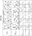
- FIG. 8A is a diagram showing a correspondence relationship between the orientation (torso angle and arm position) of the measurement subject during blood pressure measurement and the outputs (XZ coordinates and XY coordinates) of the acceleration sensor.
- FIG. 8B is a diagram showing a correspondence relationship between the orientation (torso angle and arm position) of the measurement subject during blood pressure measurement and the outputs (XZ coordinates and XY coordinates) of the acceleration sensor.
- FIG. 8C is a diagram showing a correspondence relationship between the orientation (torso angle and arm position) of the measurement subject during blood pressure measurement and the outputs (XZ coordinates and XY coordinates) of the acceleration sensor.
- FIG. 8D is a diagram showing a correspondence relationship between the orientation (torso angle and arm position) of the measurement subject during blood pressure measurement and the outputs (XZ coordinates and XY coordinates) of the acceleration sensor.
- FIG. 8E is a diagram showing a correspondence relationship between the orientation (torso angle and arm position) of the measurement subject during blood pressure measurement and the outputs (XZ coordinates and XY coordinates) of the acceleration sensor.
- FIG. 8F is a diagram showing a correspondence relationship between the orientation (torso angle and arm position) of the measurement subject during blood pressure measurement and the outputs (XZ coordinates and XY coordinates) of the acceleration sensor.
- FIG. 8G is a diagram showing a correspondence relationship between the orientation (torso angle and arm position) of the measurement subject during blood pressure measurement and the outputs (XZ coordinates and XY coordinates) of the acceleration sensor.
- FIG. 8H is a diagram showing a correspondence relationship between the orientation (torso angle and arm position) of the measurement subject during blood pressure measurement and the outputs (XZ coordinates and XY coordinates) of the acceleration sensor.
- FIGS. 9A and 9B are diagrams illustrating images to be displayed on a display device of the blood pressure monitor.
- FIGS. 10A and 10B are diagrams illustrating images to be displayed on the display device of the blood pressure monitor.
- FIG. 11 is a diagram showing portions of the overall operation flow (portions relating to detection of external compression) of FIG. 5 .
- FIG. 12 is a diagram showing a specific flow of cuff compliance calculation processing shown in FIG. 11 .
- FIG. 13 is a diagram showing a specific flow of cuff pressure existence detection processing shown in FIG. 11 .
- FIG. 14A is a diagram showing a change in the compliance ratio accompanying a change in the cuff pressure during blood pressure measurement (pressure increase process) in the case where there is no external compression on the cuff.
- FIG. 14B is a diagram showing a change in the compliance ratio accompanying a change in the cuff pressure during blood pressure measurement (pressure increase process) in the case where there is external compression on the cuff (here, in the case where the cuff is placed under the torso of the measurement subject).
- FIG. 15 is a diagram illustrating an image to be displayed on the display device of the hospital terminal.
- FIG. 16 is a diagram illustrating another image to be displayed on the display device of the hospital terminal.
- FIG. 17 is a diagram illustrating yet another image to be displayed on the display device of the hospital terminal.
- FIG. 1 shows an exterior of an electronic blood pressure monitor (indicated overall by reference numeral 1 ) according to an embodiment of the invention.
- the blood pressure monitor 1 mainly includes a blood pressure measurement cuff 20 that is to be wrapped around a measurement site of a measurement subject, and a main body 10 that is integrally attached to the cuff 20 .
- the cuff 20 has a shape that is elongated so as to wrap around the measurement site along the circumferential direction, and includes a band-shaped inner cloth 20 a that is to come into contact with the measurement site, and an outer cloth 20 b that opposes the inner cloth 20 a .
- the inner cloth 20 a and the outer cloth 20 b are formed into a bladder shape by having their peripheral edges sewn together.
- the cuff 20 contains a fluid bladder 22 (see FIG. 2 ) for compressing a measurement site.
- the surface (inner circumferential surface that is to come into contact with the measurement site) of the inner cloth 20 a is provided with many minute hooks (not shown).
- many minute loops (not shown) that engage with the above-described hooks are formed on the surface (outer circumferential surface) of the outer cloth 20 b.
- the main body 10 is integrally attached to a site between one end (end portion that is to serve as the inner circumferential end when worn) 20 e and another end (end portion that is to serve as the outer circumferential end when worn) 20 f with respect to the lengthwise direction (circumferential direction) of the cuff 20 .
- the left upper arm 90 a When the blood pressure monitor 1 is worn on the left upper arm 90 a (see FIG. 4A ) serving as the measurement site, the left upper arm 90 a is arranged in the orientation indicated by the arrow A in FIG. 1 and the cuff 20 is arranged along with the main body 10 on the front surface of the left upper arm 90 a .
- the cuff 20 is wrapped in the form of a left-handed spiral as viewed by the measurement subject.
- the corresponding surface of the inner cloth 20 a is pressed onto and fixed to a site near the inner circumferential end 20 e compared to the main body 10 of the outer cloth 20 b .
- the extra portion near the other end 20 f in the lengthwise direction (circumferential direction) of the cuff 20 is folded over so as to prevent the main body 10 from being hidden.
- FIG. 2 shows a schematic block configuration of the cuff 20 and the main body 10 of the blood pressure monitor 1 .
- the blood pressure monitor 1 includes a CPU (Central Processing Unit) 100 serving as a control unit, a display device 50 , an operation unit 52 , a memory 51 serving as a storage unit, a communication unit 59 , a power source unit 53 , a pump 32 , a valve 33 , a pressure sensor 31 , and an acceleration sensor 34 , all of which are mounted in the main body 10 .
- a CPU Central Processing Unit
- the main body 10 includes an oscillation circuit 310 that converts the output from the pressure sensor 31 into a frequency, a pump driving circuit 320 that drives the pump 32 , a valve driving circuit 330 that drives the valve 33 , and an AD converter 340 that performs AD (Analog to Digital) conversion on the output from the acceleration sensor 34 , all of which are mounted in the main body 10 .
- an oscillation circuit 310 that converts the output from the pressure sensor 31 into a frequency
- a pump driving circuit 320 that drives the pump 32
- a valve driving circuit 330 that drives the valve 33
- AD converter 340 that performs AD (Analog to Digital) conversion on the output from the acceleration sensor 34 , all of which are mounted in the main body 10 .
- the display device 50 is composed of an LCD (Liquid Crystal Display) and displays information relating to blood pressure, such as a blood pressure measurement result, in accordance with a control signal from the CPU 100 .
- LCD Liquid Crystal Display
- the operation unit 52 includes a power source switch 52 A for turning on and off the power source of the main body 10 , a measurement start switch 52 B for receiving an instruction to start blood pressure measurement, and a memory switch 52 C for calling a blood pressure measurement result stored in the memory.
- the switches 52 A, 52 B, and 52 C input operation signals corresponding to instructions performed by a user to the CPU 100 .
- the display device 50 and the operation unit 52 are provided on the front surface (upper surface in FIG. 1 ) or the side surface of the main body 10 .
- the memory 51 shown in FIG. 2 stores data of programs for controlling the blood pressure monitor 1 , data to be used to control the blood pressure monitor 1 , setting data for setting various functions of the blood pressure monitor 1 , data of measurement results of blood pressure values, data indicating whether or not there is later-described external compression on the cuff 20 , whether or not there is bodily movement of a measurement subject, and the orientation of the measurement subject, and the like. Also, the memory 51 is used as a work memory or the like for when a program is executed.
- the CPU 100 performs control for driving the pump 32 and the valve 33 according to the operation signal from the operation unit 52 . Also, based on a signal from the pressure sensor 31 , the CPU 100 performs control for calculating the blood pressure values and control for detecting whether or not there is external compression on the cuff 20 . Furthermore, based on the output of the acceleration sensor 34 , the CPU 100 performs control for detecting whether or not there is bodily movement of the measurement subject and the orientation of the measurement subject. These controls will be described in detail later.
- the communication unit 59 is controlled by the CPU 100 to transfer predetermined information to an external apparatus via the network 900 , and to receive information from the external apparatus via the network 900 and transfer it to the CPU 100 .
- Communication via the network 900 may be performed wirelessly or using a wire.
- the network 900 is the Internet, but there is no limitation to this, and it is also possible to use another type of network such as an in-hospital LAN (Local Area Network), or one-to-one communication using a USB cable or the like.
- the power source unit 53 supplies power to the units, namely the CPU 100 , the pressure sensor 31 , the pump 32 , the valve 33 , the acceleration sensor 34 , the display device 50 , the memory 51 , the communication unit 59 , the oscillation circuit 310 , the pump driving circuit 320 , the valve driving circuit 330 , and the AD converter 340 .
- the pump 32 , the valve 33 , and the pressure sensor 31 are connected to the fluid bladder 22 contained in the cuff 20 via a common air tube 39 serving as a tube system.
- the pump 32 supplies air to the fluid bladder 22 through the air tube 39 in order to increase the pressure (cuff pressure) in the fluid bladder 22 contained in the cuff 20 .
- the valve 33 is a solenoid valve that is controlled so as to open and close through application of a current, and is used to control the cuff pressure by discharging the air in the air bladder 22 through the air tube 39 or sealing the air in the air bladder 22 .
- the pump driving circuit 320 drives the pump 32 based on the control signal provided by the CPU 100 .
- the valve driving circuit 330 opens and closes the valve 33 based on the control signal provided from the CPU 100 .
- the pressure sensor 31 is a piezoresistance pressure sensor that detects the pressure of the cuff 20 (fluid bladder 22 ) through the air tube 39 , and in this example, the pressure sensor 31 detects a pressure obtained with reference to atmospheric pressure (with atmospheric pressure being set to zero) and outputs the detected pressure as a cuff pressure signal Pc in a time series.
- the oscillation circuit 310 oscillates based on an electricity signal value that is based on a change in the electric resistance caused by a piezoresistance effect from the pressure sensor 31 , and outputs a frequency signal having a frequency corresponding to the electricity signal value of the pressure sensor 31 to the CPU 100 .
- the output of the pressure sensor 31 is used to calculate the blood pressure values (includes systolic blood pressure and diastolic blood pressure; the same applies in the description hereinafter) of the measurement subject 90 through an oscillomertic method.
- the output of the pressure sensor 31 is used to determine whether or not there is external compression on the cuff 20 by calculating the cuff compliance (amount of air needed to change the cuff pressure by a unit pressure 1 mmHg).
- cuff compliance amount of air needed to change the cuff pressure by a unit pressure 1 mmHg.
- external compression occurs when the cuff 20 and the left upper arm 90 a serving as the measurement site are placed under the torso of the measurement subject who is lying down, and are compressed by the torso and the bed surface.
- the acceleration sensor 34 is composed of a triaxial acceleration sensor that is integrally built into the main body 10 .
- the acceleration sensor 34 outputs an acceleration signal indicating acceleration in three mutually orthogonal directions of the main body 10 and accordingly, of the cuff 20 integrally attached to the main body 10 , to the CPU 100 via the AD converter 340 .
- an XYZ orthogonal coordinate system is set with the position of the acceleration sensor 34 in the main body 10 serving as the origin.
- the Z axis is set facing outward orthogonally to the front surface of the main body 10 .
- the Y axis is set in an orientation facing from the knee to the shoulder along the left upper arm 90 a of the measurement subject 90 in a state in which the blood pressure monitor 1 is worn on the left upper arm 90 a serving as the measurement site as described above.
- the X axis is set orthogonally to the Y axis and the Z axis (the X axis faces approximately leftward as viewed by the measurement subject 90 , but this depends on the orientation of the measurement subject 90 as well).
- the measurement subject 90 is in a supine orientation (supine position) on the bed surface 99 , but in actuality, especially in the case of night-time blood pressure measurement, the measurement subject 90 can be in various orientations.
- the measurement subject can be in an orientation in which the angle ⁇ of the torso is changed with respect to the bed surface 99 .
- the output of the acceleration sensor 34 is used to detect whether or not there is bodily movement of the measurement subject 90 .
- the output of the acceleration sensor 34 is used to detect the orientation of the measurement subject 90 according to the direction (e.g., in FIGS. 4A and 4B , the directions of the gravity acceleration vectors G with respect to the XYZ orthogonal coordinate system are different) of a gravity acceleration vector G with respect to the above-described XYZ orthogonal coordinate system.
- FIG. 6A shows a cuff pressure signal Pc, a pulse wave signal SM, a pump driving signal Vout, and a cuff compliance CL during blood pressure measurement (pressure increase process) in the case where there is no external compression on the cuff 20 .
- FIG. 6B shows a cuff pressure signal Pc, a pulse wave signal SM, a pump driving signal Vout, and a cuff compliance CL during blood pressure measurement (pressure increase process) in the case where there is external compression on the cuff 20 (here, a case in which the cuff 20 is placed under the torso of the measurement subject 90 ).
- the cuff pressure signal Pc indicates the pressure of the cuff 20 (fluid bladder 22 ) that is detected via the air tube 39 and the oscillation circuit 310 by the pressure sensor 31 .
- the pulse wave signal SM indicates a signal extracted through a filter (not shown) as a fluctuation component of the cuff pressure signal Pc (the pulse wave signal SM is used to calculate the blood pressure values through an oscillometric method).
- the pump driving signal Vout indicates a square wave signal (pulse width modulation signal) output from the CPU 100 to the pump driving circuit 320 in order to increase the pressure of the cuff 20 .
- the cuff compliance CL is obtained as values (calculated for each predetermined pressure segment) CMa, CMb, CMc, CMd, . .
- an envelope EV is added to the sequence formed by the values CMa, CMb, CMc, CMd, . . . of the cuff compliance CL.
- the reason for this is because if there is no external compression on the cuff 20 , the volume of the cuff easily expands in the low pressure region (0 mmHg to less than 40 mmHg), and therefore a large amount of air is needed to raise the cuff pressure, but the volume of the cuff 20 is substantially less likely to increase when the tensile force of the cuff 20 increases due to the cuff pressure rising by a certain degree.
- the cuff compliance CL has a maximum value in the pressure increase process.
- the cuff compliance CL changes gradually from a low value (varies due to the influence of the tensile force of wrapping the cuff around the measurement site) to a high value.
- the torso is pushed away by the top of the cuff 20 due to the inflation of the cuff 20 , and therefore the cuff compliance CL gradually decreases and is saturated, similarly to the case shown in FIG. 6A (the case in which there is no external compression).
- the cuff compliance CL has a maximum value accompanying the rising of the cuff pressure.
- FIG. 7 illustrates the outputs (acceleration signals) of the acceleration sensor 34 during blood pressure measurement.
- the measurement subject 90 is essentially in a resting state, and therefore an output ⁇ x in the X-axis direction of the acceleration sensor 34 , an output ⁇ y in the Y-axis direction, and an output ⁇ z in the Z-axis direction have approximately constant values.
- the outputs ⁇ x , ⁇ y , and ⁇ z change as indicated by ⁇ x 1, ⁇ y 1, and ⁇ z 1.
- the CPU 100 functions as a bodily movement detection unit, and during blood pressure measurement, obtains average values ⁇ x >, ⁇ y >, and ⁇ z > of the outputs ⁇ x, ⁇ y , and ⁇ z of the acceleration sensor 34 in each unit period (e.g., one second or several seconds). Furthermore, the CPU 100 obtains fluctuation amounts ( ⁇ x ⁇ x >), ( ⁇ y ⁇ y >), and ( ⁇ z ⁇ z >) by which the acceleration outputs ⁇ x , ⁇ y , and ⁇ z of the times in the unit period fluctuate with respect to the average values ⁇ x >, ⁇ y >, and ⁇ z >.
- FIGS. 8A to 8H show correspondence relationships between the orientation (torso angle and arm position) of the measurement subject 90 during blood pressure measurement and the normalized outputs (XZ coordinates and XY coordinates) of the acceleration sensor 34 .
- FIGS. 8A to 8H show eight types of “torso angles” as torso patterns in the first rows (top rows).
- “Torso angle” means the angle (indicated by reference numeral ⁇ in FIG. 4B ) by which the flat torso 90 b is rotated about a center (approximately matches the spine) in a view along the body height direction (in this example, in a view from head to feet) of a person lying on a bed surface.
- the torso 90 b is in the supine position and the torso angle is 0 degrees.
- the torso 90 b is between the supine position and the right side position, and the torso angle is 20 degrees.
- the torso 90 b is in the right side position and the torso angle is 90 degrees.
- the torso 90 b is between the right side position and the prone position, and the torso angle is 160 degrees.
- the torso 90 b is in the prone position and the torso angle is 180 degrees.
- the torso 90 b is between the prone position and the left side position, and the torso angle is 200 degrees.
- the torso 90 b is in the left side position and the torso angle is 270 degrees.
- the torso 90 b is between the left side position and the supine position, and the torso angle is 340 degrees.
- the second rows each show four or three types of representative arm positions serving as arm patterns corresponding to arm positions that are varied with respect to a person's torso.
- the left upper arm 90 a in the first column (leftmost column), the left upper arm 90 a is at a “body-lateral” position of extending along the lateral side of the torso 90 b
- the left upper arm 90 a in the second column, the left upper arm 90 a is at a “body-side separated” position of being separated laterally from the torso 90 b
- the left upper arm 90 a is at an “on-chest” position of being placed on the torso 90 b
- the fourth column in the fourth column (rightmost column) the left upper arm 90 a is in a “hurrah” position of being raised toward the head.
- the left upper arm 90 a in the first columns (leftmost columns), the left upper arm 90 a is at a “back-side” position of being rotated rearward of the torso 90 b , in the second columns, the left upper arm 90 a is at a “body-lateral” position of extending along the lateral side of the torso 90 b , in the third columns, the left upper arm 90 a is at a “chest-side” position of being rotated frontward of the torso 90 b , and in the fourth columns (rightmost columns), the left upper arm 90 a is at a “hurrah” position of being raised toward the head.
- FIG. 8B, 8C, and 8D in the first columns (leftmost columns), the left upper arm 90 a is at a “back-side” position of being rotated rearward of the torso 90 b , in the second columns, the left upper arm 90 a is at a “body-lateral” position of extending along the lateral side of the torso 90
- the left upper arm 90 a in the first column (leftmost column), the left upper arm 90 a is at a “body-lateral” position of extending along the lateral side of the torso 90 b , in the second column, the left upper arm 90 a is at a “body-side separated” position of being separated laterally from the torso 90 b , and in the third column, (rightmost column), the left upper arm 90 a is in a “hurrah” position of being raised toward the head.
- the left upper arm 90 a in the first column (leftmost column), the left upper arm 90 a is at a “body-lateral” position of extending along the lateral side of the torso 90 b , in the second column, the left upper arm 90 a is at a “body-side separated” position of being separated laterally from the torso 90 b , and in the third column, (rightmost column), the left upper arm 90 a is in a “hurrah” position of being raised toward the head.
- the left upper arm 90 a in the first column (leftmost column), the left upper arm 90 a is at a “back-side” position of being rotated rearward of the torso 90 b , in the second column, the left upper arm 90 a is at a “body-lateral” position of extending along the lateral side of the torso 90 b , and in the third column (rightmost column), the left upper arm 90 a is at a position of being rotated frontward of the torso 90 b .
- FIG. 8F in the first column (leftmost column), the left upper arm 90 a is at a “back-side” position of being rotated rearward of the torso 90 b , in the second column, the left upper arm 90 a is at a “body-lateral” position of extending along the lateral side of the torso 90 b , and in the third column (rightmost column), the left upper arm 90 a is at a position of being rotated frontward of the torso 90 b .
- the left upper arm 90 a in the first column (leftmost column), the left upper arm 90 a is at a “chest-front separated” position of being separated frontward from the torso 90 b , in the second column, the left upper arm 90 a is at a “body-lateral” position of extending along the lateral side of the torso 90 b , and in the third column (rightmost column), the left upper arm 90 a is at a “hurrah” position of being raised toward the head. Also, in FIG.
- the left upper arm 90 a in the first column (leftmost column), the left upper arm 90 a is at a “chest-front” position of being rotated frontward from the torso 90 b , in the second column, the left upper arm 90 a is at a “body-lateral” position of extending along the lateral side of the torso 90 b , and in the third column (rightmost column), the left upper arm 90 a is at a “hurrah” position of being raised toward the head.
- the orientations of the measurement subject 90 during blood pressure measurement are specified using combinations of the “torso angles” in the first rows (top rows) and the “arm positions” in the second rows corresponding thereto in FIGS. 8A to 8H .
- the normalized (normalized to 1) outputs of the acceleration sensor 34 in cases where the measurement subject 90 is in orientations specified using combinations of the “torso angles” in the first rows and the “arm positions” in the second rows are indicated in XZ coordinate planes and XY coordinate planes.
- the measurement subject 90 is substantially in a resting state, and the outputs (the above-described average values ⁇ x >, ⁇ y >, and ⁇ z >) of the acceleration sensor 34 correspond to the direction of the gravity acceleration vector G corresponding to the XYZ orthogonal coordinate system set in the main body 10 .
- the measurement subject 90 is in an orientation specified using the combination in which the “torso angle” is 0 degrees and the “arm position” is “body-side separated” in the second column of FIG.
- the measurement subject 90 is in an orientation specified using the combination in which the “torso angle” is 0 degrees and the “arm position” is “on-chest” in the third column of FIG.
- the normalized outputs of the acceleration sensor 34 are detected as point a xz where 0 ⁇ X ⁇ 1 and 0 ⁇ Z ⁇ 1 (first quadrant) in the XZ coordinate plane in the third row, and as point a xy where 0 ⁇ X ⁇ 1 and ⁇ 1 ⁇ Y ⁇ 0 (fourth quadrant) are satisfied in the XY coordinate plane in the fourth row.
- the measurement subject 90 is in an orientation specified using the combination in which the “torso angle” is 0 degrees and the “arm position” is “hurrah” in the fourth column (rightmost column) of FIG.
- the normalized outputs of the acceleration sensor 34 are detected as point a xz where ⁇ 1 ⁇ X ⁇ 0 and ⁇ 1 ⁇ Z ⁇ 0 (third quadrant) in the XZ coordinate plane in the third row, and as point a xy where ⁇ 1 ⁇ X ⁇ 0 and ⁇ 1 ⁇ Y ⁇ 0 (third quadrant) in the XY coordinate plane in the fourth row.
- FIGS. 8A to 8H when the measurement subject 90 is in an orientation specified using a combination of a “torso angle” in a first row and an “arm position” in a second row, the orientation and the normalized output (combination of XZ coordinates and XY coordinates) of the acceleration sensor 34 are in a one-to-one correspondence. Accordingly, if the normalized outputs (combination of the XZ coordinates and the XY coordinates) of the acceleration sensor 34 are specified, the orientation of the measurement subject 90 , that is, the combination of the “torso angle” and the “arm position” is specified. In other words, the orientation of the measurement subject 90 is determined.
- the CPU 100 functions as an orientation detection unit and determines the orientation of the measurement subject 90 based on the outputs (the above-described average values ⁇ x >, ⁇ y >, and ⁇ z > are desirable) of the acceleration sensor 34 . Accordingly, the orientation of the measurement subject can be detected easily.
- illustrations A- 1 to A- 4 shown in the first row in FIG. 8A illustrations B- 1 to B- 4 shown in the first row in FIG. 8B , illustrations C- 1 to C- 4 shown in the first row in FIG. 8C , illustrations D- 1 to D- 4 shown in the first row in FIG. 8D , illustrations E- 1 to E- 3 shown in the first row in FIG. 8E , illustrations F- 1 to F- 3 shown in the first row in FIG. 8F , illustrations G- 1 to G- 3 shown in the first row in FIG. 8G , and illustrations H- 1 to H- 3 shown in the first row in FIG.
- A- 1 to A- 4 , B- 1 to B- 4 , C- 1 to C- 4 , D- 1 to D- 4 , E- 1 to E- 3 , F- 1 to F- 3 , G- 1 to G- 3 , and H- 1 to H- 3 correspond to combinations obtained using the torso patterns and arm patterns as materials.
- the torso 90 b of the measurement subject 90 is expressed as an elongated circle.
- the head 90 h of the measurement subject 90 is indicated by a circle and a small triangle corresponding to the nose, in a state of being overlaid slightly shifted in the short axis direction.
- the left upper arm 90 a around which the cuff 20 is wrapped is indicated by a circle on the left side of the elongated circle indicating the torso 90 b .
- the main body 10 attached integrally to the cuff 20 is indicated by a rectangle.
- the elongated circle indicating the torso 90 b is extended in the horizontal direction so as to indicate that the torso angle is 0 degrees (supine position).
- the circle indicating the head 90 h of the measurement subject 90 is overlaid shifted upward of the elongated circle indicating the torso 90 b (note that up, down, left, and right in this paragraph indicate up, down, left, and right in FIG. 8A ).
- the circle indicating the left upper arm 90 a is adjacent to the left of the elongated circle indicating the torso 90 b so as to indicate “body-lateral”.
- the rectangle indicating the main body 10 is located on the upper portion of the circle indicating the left upper arm 90 a so as to indicate that the main body 10 is on the front surface of the left upper arm 90 a .
- the circle indicating the left upper arm 90 a is separated from the elongated circle indicating the torso 90 b so as to indicate “body-side separated”.
- the circle indicating the left upper arm 90 a is located above and to the left of the elongated circle indicating the torso 90 b so as to indicate “on-chest”.
- the circle indicating the left upper arm 90 a is located above and to the left of the elongated circle indicating the torso 90 b and the rectangle indicating the main body 10 is located below the circle indicating the left upper arm 90 a so as to indicate “hurrah”.
- the other portions of the illustrations A- 2 to A- 4 are drawn in the same manner as those of the illustration A- 1 .
- the elongated circle indicating the torso 90 b is elongated in the vertical direction so as to indicate that the torso angle is 270 degrees (left side position).
- the circle indicating the head 90 h of the measurement subject 90 is overlaid shifted to the left of the elongated circle indicating the torso 90 b (note that up, down, left, and right in this paragraph indicate up, down, left, and right in FIG. 8G ).
- the circle indicating the left upper arm 90 a is separated from the elongated circle indicating the torso 90 b so as to indicate “chest-front separated”.
- the rectangle indicating the main body 10 is located on the left portion of the circle indicating the left upper arm 90 a so as to indicate that the main body 10 is on the front surface of the left upper arm 90 a .
- the circle indicating the left upper arm 90 a is adjacent to the bottom of the elongated circle indicating the torso 90 b so as to indicate “body-lateral”.
- the circle indicating the left upper arm 90 a is located downward and to the left of the elongated circle indicating the torso 90 b and the rectangle indicating the main body 10 is located on the right portion of the circle indicating the left upper arm 90 a so as to indicate “hurrah”.
- the other portions of the illustrations G- 2 to G- 3 are drawn in the same manner as those of the illustration G- 1 .
- the orientation of the measurement subject 90 can be schematically indicated using the illustrations A- 1 to A- 4 , B- 1 to B- 4 , C- 1 to C- 4 , D- 1 to D- 4 , E- 1 to E- 3 , F- 1 to F- 3 , G- 1 to G- 3 , and H- 1 to H- 3 , that is, as a combination of a torso pattern indicating the “torso angle” and an arm pattern indicating the “arm position”.
- the normalized outputs (XZ coordinates and XY coordinates) of the acceleration sensor 34 in the third rows and the fourth rows in FIGS. 8A to 8H and the illustrations A- 1 to A- 4 , B- 1 to B- 4 , C- 1 to C- 4 , D- 1 to D- 4 , E- 1 to E- 3 , F- 1 to F- 3 , G- 1 to G- 3 , and H- 1 to H- 3 in the first rows are stored in a one-to-one correspondence as an orientation table in the memory 51 .
- image data including an illustration of an orientation of the measurement subject 90 can be created rapidly with simple processing during later-described display processing (step ST 110 in FIG. 5 ).
- FIG. 5 illustrates an overall operation flow of the blood pressure monitor 1 .
- the blood pressure monitor 1 starts the blood pressure measurement.
- the CPU 100 initializes a memory region for processing and outputs a control signal to the valve driving circuit 330 .
- the valve driving circuit 330 opens the valve 33 to discharge the air in the fluid bladder 22 of the cuff 20 .
- control for adjusting the pressure sensor 31 to 0 mmHg is performed.
- the CPU 100 closes the valve 33 via the valve driving circuit 330 , and thereafter drives the pump 32 via the pump driving circuit 320 while monitoring the cuff pressure signal Pc using the pressure sensor 31 (and the air tube 39 and the oscillation circuit 310 ), and thus performs control for sending air to the fluid bladder 22 . Accordingly, the fluid bladder 22 is inflated and the cuff pressure gradually increases (step ST 101 ).
- the CPU 100 integrates the pump driving signal Vout for the pump driving circuit 320 to acquire data indicating the cuff compliance CL, as illustrated in FIGS. 6A and 6B (step ST 102 ).
- the CPU 100 acquires the outputs of the acceleration sensor 34 (step ST 103 ).
- the CPU 100 acquires the pulse wave signal SM serving as a fluctuation component through a filter (not shown) from the cuff pressure signal Pc (step ST 104 ).
- the CPU 100 functions as a blood pressure measurement unit and attempts calculation of the blood pressure values (systolic blood pressure SBP and diastolic blood pressure DBP) and the pulse by applying a known algorithm through the oscillometric method based on the pulse wave signal SM acquired at this time point (step ST 105 ).
- step ST 105 if the blood pressure values cannot yet be calculated due to insufficient data (NO in step ST 105 ), the processing of steps ST 101 to ST 105 are repeated as long as the cuff pressure has not reached the upper limit pressure (in the interest of safety, the upper limit pressure is set in advance to 300 mmHg, for example) (NO in step ST 106 ).
- step ST 105 When the blood pressure values and pulse can be thus calculated (YES in step ST 105 ), the processing advances to step ST 107 , and the CPU 100 detects whether or not there is external compression on the cuff 20 , whether or not there is bodily movement of the measurement subject 90 , and the orientation of the measurement subject 90 .
- the CPU 100 functions as an external compression detection unit and detects whether or not there is external compression on the cuff 20 based on whether or not the cuff compliance CL is at a maximum value in the pressure increase process. Specifically, when the cuff compliance CL decreases monotonically as illustrated in FIG. 6A in the pressure increase process, it is determined that there is no external compression. On the other hand, when the cuff compliance CL has a maximum value as illustrated in FIG. 6B in the pressure increase process, it is determined that there is external compression.
- the CPU 100 functions as a bodily movement detection unit and detects whether or not there is bodily movement of the measurement subject 90 based on changes in the output of the acceleration sensor 34 . Specifically, in each unit period (e.g., one second or multiple seconds) in the pressure increase process, the CPU 100 obtains the average values ⁇ x >, ⁇ y >, and ⁇ z > of the outputs ⁇ x , ⁇ y , and ⁇ z of the acceleration sensor 34 illustrated in FIG. 7 .
- the CPU 100 functions as an orientation detection unit and detects the orientation of the measurement subject 90 based on the outputs (the above-described average values ⁇ x >, ⁇ y >, ⁇ z >) of the acceleration sensor 34 in the pressure increase process. Specifically, the CPU 100 determines whether or not the orientation of the measurement subject 90 corresponds to an orientation in an illustration in one of the first rows (top rows) in FIGS. 8A to 8H based on the correspondence relationship between the normalized outputs (XZ coordinates and XY coordinates) of the acceleration sensor 34 in the third rows and fourth rows of FIGS.
- step ST 108 in FIG. 5 the CPU 100 stores the measurement number, measurement time, measured blood pressure values (systolic blood pressure SBP and diastolic blood pressure DBP), pulse, whether or not there is external compression on the cuff 20 , whether or not there is bodily movement of the measurement subject 90 , and the orientation of the measurement subject 90 , in association with each other in the memory 51 .
- measured blood pressure values systolic blood pressure SBP and diastolic blood pressure DBP
- the data stored in the memory 51 is accumulated for each measurement of the blood pressure, as shown in the following data table (Table 1) for example.
- Table 1 data table for example.
- the night-time blood pressure measurement is performed every 30 seconds.
- the orientation of the measurement subject 90 is indicated by the reference sign specifying an illustration in a first row (top row) of FIGS. 8A to 8H .
- the reference sign “K- 1 ” in the “orientation” column indicates an orientation (e.g., an orientation corresponding to the first illustration K- 1 in later-described FIG. 15 ) in which the measurement subject 90 is in a sitting position and the left upper arm 90 a serving as the measurement site naturally hangs downward.
- the “correction using altitude difference” column will be described later.
- step ST 109 in FIG. 5 the CPU 100 functions as a blood pressure correction unit and corrects the measured blood pressure values according to the obtained orientation of the measurement subject 90 .
- the measured blood pressure values are shifted from the actual values (values in the case where the heart and the measurement site are at the same height level) according to an altitude difference between the heart and the measurement site (in this example, the left upper arm 90 a ) of the measurement subject 90 .
- a correction amount that is thought to be suitable due to experience is set in advance according to the obtained orientation of the measurement subject 90 , as shown in the “correction amount” column in “correction according to altitude difference” of the data table (Table 1). For example, with the orientation “A- 1 ”, the heart and the left upper arm 90 a of the measurement subject 90 are at the same height level, and therefore the correction amount is set to 0 [mmHg].
- the left upper arm 90 a With the orientation “C- 2 ”, the left upper arm 90 a is at a higher level than the heart of the measurement subject 90 , and therefore the correction amount is set to 16 [mmHg]. Also, with the orientation “B- 2 ”, the altitude difference between the heart and the left upper arm 90 a of the measurement subject 90 is at a level between that of the orientation “A- 1 ” and that of the orientation “C- 2 ”, and therefore the correction amount is set to 8 [mmHg].
- the CPU 100 adds the pre-set correction amount to the measured blood pressure value according to the obtained orientation of the measurement subject 90 .
- the obtained orientation is “C- 2 ”
- the obtained orientation is “B- 2 ”
- the CPU 100 additionally stores the correction amount corresponding to the orientation and the corrected blood pressure values (systolic blood pressure SBP′ and diastolic blood pressure DBP′) in the data table (Table 1) in the memory 51 in association with the measurement number, the measurement time, the measured blood pressure values (systolic blood pressure SBP and diastolic blood pressure DBP), the pulse, whether or not there is external compression on the cuff 20 , whether or not there is bodily movement of the measurement subject 90 , and the orientation of the measurement subject 90 .
- Table 1 data table
- the CPU 100 refers to the data table (Table 1) in the memory 51 , functions as a notification unit, and displays the blood pressure values (systolic blood pressure SBP and diastolic blood pressure DBP) measured in this instance of measurement, the pulse, whether or not there is external compression on the cuff 20 , whether or not there is bodily movement of the measurement subject 90 , and the orientation of the measurement subject 90 on the display screen of the display device 50 .
- Table 1 data table
- DBP diastolic blood pressure
- step ST 111 in FIG. 5 the CPU 100 performs control for opening the valve 33 via the valve driving circuit 330 and discharging the air in the fluid bladder 22 of the cuff 20 .
- the acquisition of the cuff compliance data, the acquisition of the output of the acceleration sensor, the acquisition of the pulse wave signal, and the calculation of the blood pressure values are performed in the process of increasing the pressure of the cuff 20 , but there is no limitation to this.
- the acquisition of the output of the acceleration sensor, the acquisition of the pulse wave signal, and the calculation of the blood pressure values may be performed in the pressure decrease process.
- an orientation region 50 f for displaying the orientation of the measurement subject 90 as an illustration are set on the display screen of the display device 50 .
- An illustration J- 1 indicating that there is bodily movement is composed of a circle m 1 indicating the head of the measurement subject 90 , a rounded-corner rectangle (a rectangle with rounded corners) m 2 indicating the torso of the measurement subject 90 , and a waveform mark m 3 indicating motion of the body.
- the illustration J- 2 indicating that there is external compression is obtained approximately by adding a waveform mark m 4 indicating the bed surface to the illustration G- 2 .
- the illustrations J- 1 and J- 2 are stored in advance in the memory 51 . Note that when there is no bodily movement, the “bodily movement” region 50 d is blank (empty) and when there is no external compression, the “compression” region 50 e is blank (empty).
- the illustration corresponding to the content (reference numeral specifying the illustration) of the “orientation” column of the data table (Table 1) is selected from among the multiple illustrations A- 1 to A- 4 , B- 1 to B- 4 , C- 1 to C- 4 , D- 1 to D- 4 , E- 1 to E- 3 , F- 1 to F- 3 , G- 1 to G- 3 , and H- 1 to H- 3 in the first rows (top rows) in FIGS. 8A to 8H , and is displayed in the orientation region 50 f . Accordingly, the image data including the illustration indicating the orientation of the measurement subject 90 can be rapidly created with simple processing.
- a systolic blood pressure SBP of 117 mmHg, a diastolic blood pressure DBP of 81 mmHg, and a pulse of 70 BPM that were measured in the current instance of measurement are displayed as numerical values in the “systolic blood pressure” region 50 a , the “diastolic blood pressure” region 50 b , and the “pulse” region 50 c , similarly to the example above.
- the fact that there is no bodily movement is displayed as a blank in the “bodily movement” region 50 d .
- the fact that there is no external compression is displayed as a blank in the “compression” region 50 e .
- the orientation of the measurement subject 90 is displayed as an illustration A- 1 in the orientation region 50 f.
- a systolic blood pressure SBP of 111 mmHg, a diastolic blood pressure DBP of 68 mmHg, and a pulse of 70 BPM that were measured in the current instance of measurement are displayed as numerical values in the “systolic blood pressure” region 50 a , the “diastolic blood pressure” region 50 b , and the “pulse” region 50 c .
- the fact that there is no bodily movement is displayed as a blank in the “bodily movement” region 50 d .
- the fact that there is external compression is displayed as the illustration J- 2 in the “compression” region 50 e .
- the orientation of the measurement subject 90 is displayed as the illustration G- 2 in the orientation region 50 f.
- a systolic blood pressure SBP of 131 mmHg, a diastolic blood pressure DBP of 85 mmHg, and a pulse of 70 BPM that were measured in the current instance of measurement are displayed as numerical values in the “systolic blood pressure” region 50 a , the “diastolic blood pressure” region 50 b , and the “pulse” region 50 c .
- the fact that there is bodily movement is displayed as the illustration J- 1 in the “bodily movement” region 50 d .
- the fact that there is no external compression is displayed as a blank in the “compression” region 50 e .
- the orientation of the measurement subject 90 is displayed as the illustration A- 1 in the orientation region 50 f.
- the user can find out the blood pressure values (systolic blood pressure SBP and diastolic blood pressure DBP) and the value of the pulse that were measured in this instant of measurement by viewing the numerical values in the “systolic blood pressure” region 50 a , the “diastolic blood pressure” region 50 b , and the “pulse” region 50 c on the display screen of the display device 50 .
- blood pressure values systolic blood pressure SBP and diastolic blood pressure DBP
- the user can intuitively understand whether or not there is bodily movement of the measurement subject 90 , whether or not there is external compression on the cuff 20 , and the orientation of the measurement subject 90 during blood pressure measurement.
- step ST 112 the fact that an error occurred is stored in the memory 51 in association with the measurement time.
- “Error” is stored in the columns for the measured blood pressure values (systolic blood pressure SBP and diastolic blood pressure DBP) in the data table (Table 1) in the memory 51 . Even if this error is present, it is desirable to store the detection results in the “external compression” column, the “bodily movement” column, and the “orientation” column of the data table (Table 1), if possible.
- step ST 110 in FIG. 5 “Error” is displayed as character strings in the “systolic blood pressure” region 50 a and the “diastolic blood pressure” region 50 b on the display screen of the display device 50 in this example, and illustrations indicating the detection results are displayed in the “bodily movement” region 50 d , the “compression” region 50 e , and the orientation region 50 f .
- the user can infer the cause of the error by viewing the illustrations in the “bodily movement” region 50 d , the “compression” region 50 e , and the orientation region 50 f.
- FIG. 14A shows change in a compliance ratio accompanying change in the cuff pressure during blood pressure measurement (pressure increase process) in the case where there is no external compression on the cuff 20 .
- FIG. 14B shows change in a cuff compliance ratio accompanying change in the cuff pressure during blood pressure measurement (pressure increase process) in the case where there is external compression on the cuff 20 (here, a case in which the cuff 20 is placed under the torso of the measurement subject 90 ).
- “compliance ratio” means the ratio between the cuff compliance calculated during blood pressure measurement and the cuff compliance (referred to as “reference cuff compliance”) measured once as a reference in a state in which there is no external compression on the cuff 20 .
- (compliance ratio) (cuff compliance measured during blood pressure measurement)/(reference cuff compliance).
- the compliance ratio is used to more accurately determine whether or not there is external compression on the cuff 20 .
- the data of the compliance ratio during multiple instances of blood pressure measurement is denoted by respective signs at the locations of cuff pressures 10 mmHg, 30 mmHg, 50 mmHg, 70 mmHg, 90 mmHg, 110 mmHg, 130 mmHg, 150 mmHg, . . . .
- the average values of the data of the multiple instances are denoted as a line graph CLR.
- the compliance ratio is approximately constant (except for the location of the cuff pressure 10 mmHg in the low pressure region).
- the compliance ratio graph CLR
- the compliance ratio has a maximum value in the intermediate pressure region (40 mmHg or more and 120 mmHg or less) in the pressure increase process.
- the compliance ratio (CLR) is less than a first threshold REF 1 (in this example, 0.7) in the low pressure region (0 mmHg to less than 40 mmHg) and the compliance ratio CLR is greater than or equal to a second threshold REF 2 (in this example, 1.3) in the intermediate pressure region (40 mmHg or more and 120 mmHg or less).
- the CPU 100 functions as an external compression detection unit and executes the operation flow shown in FIGS. 11 to 13 .
- FIG. 11 shows portions of the overall operation flow (portions related to detection of external compression) in FIG. 5 . That is, if blood pressure measurement is in progress (YES in step ST 201 of FIG. 11 ), the cuff pressure is acquired and the current cuff pressure is set as pc[i] (step ST 202 ).
- calculation for a pump driving signal (duty) is performed, and the current pump driving voltage is set as duty[i] (step ST 203 ).
- cuff compliance calculation processing FIG. 12 for obtaining a cuff compliance is performed (step ST 204 ).
- step ST 206 of FIG. 11 the index i indicating the number of instances of processing is incremented (increased by one) in step ST 206 of FIG. 11 , and the processing of steps ST 202 and ST 203 and steps ST 301 to ST 303 in FIG. 12 is repeated.
- the current cuff pressure pc reaches 10 mmHg in step ST 304 (when pc[i] ⁇ 10 mmHg and pc[i ⁇ 1] ⁇ 10 mmHg)
- the addition variable duty_sum is cleared, and the processing returns to the flow of FIG. 11 (NO in step ST 205 ).
- step ST 206 of FIG. 11 the index i indicating the number of instances of processing is incremented in step ST 206 of FIG. 11 , and the processing of steps ST 202 and ST 203 and steps ST 301 to ST 303 of FIG. 12 is repeated.
- the current cuff pressure pc[i] reaches 30 mmHg in step ST 304 (when pc[i] ⁇ 30 mmHg and pc[i ⁇ 1] ⁇ 30 mmHg)
- step ST 205 of FIG. 11 corresponds to step ST 105 of FIG. 5 .
- step ST 207 external compression existence detection processing for determining whether or not there is external compression on the cuff 20 is performed.
- the CPU 100 functions in advance as a reference data acquisition unit, and in a state in which the cuff 20 is worn on a left upper arm 90 a and there is no external compression, the CPU 100 increases the pressure in the cuff 20 and calculates the reference cuff compliance (reference signal COMP_STD) that is to serve as a reference at the times of the cuff pressures 10 mmHg, 30 mmHg, 50 mmHg, 70 mmHg, 90 mmHg, and 110 mmHg.
- reference signal COMP_STD reference cuff compliance
- step ST 403 a compression flag indicating that there was external compression is set.
- COMP_STDs in Eq. 0 to Eq. 5 are indicated by the same reference signs for the sake of simplicity, they respectively indicate the reference cuff compliances at the times of the cuff pressures 10 mmHg, 30 mmHg, 50 mmHg, 70 mmHg, 90 mmHg, and 110 mmHg (the same applies also to Eq. 6 to Eq. 11, which will be described next).
- step ST 401 it is determined that there is no external compression in the case where, regarding the low pressure region (0 mmHg to less than 40 mmHg), Comp(0)/COMP_STD ⁇ 0.7 (Eq.6) or Comp(1)/COMP_STD ⁇ 0.7 (Eq.7) is established (NO in step ST 401 ), or, regarding the intermediate pressure region (40 mmHg or more and 120 mmHg or less), Comp(2)/COMP_STD ⁇ 1.3 (Eq.8) or Comp(3)/COMP_STD ⁇ 1.3 (Eq.9) or Comp(4)/COMP_STD ⁇ 1.3 (Eq.10) or Comp(5)/COMP_STD ⁇ 1.3 (Eq.11) is established (NO in step ST 402 ). In this case, in step ST 404 , a no compression flag indicating that there was no external compression is set.
- step ST 403 When the compression flag is set in step ST 403 , “1”, which indicates that there is external compression in the current instance of blood pressure measurement, is stored in the “external compression” column of the above-described data table (Table 1). On the other hand, when the no compression flag is set in step ST 404 , “0”, which indicates that there is no external compression in the current instance of blood pressure measurement, is stored in the “external compression” column of the data table (Table 1).
- step ST 208 compression information (e.g., the illustration J- 2 shown in FIGS. 9A and 10B ) indicating that there was external compression in the present instance of blood pressure measurement is displayed in step ST 209 (corresponds to step ST 110 of FIG. 5 ).
- FIG. 3 shows a block configuration of a hospital terminal 200 that can communicate with the blood pressure monitor 1 via a network 900 .
- the hospital terminal 200 is composed of a commercially-available personal computer, includes a main body 200 M, and includes a control unit 210 composed of a CPU, a memory 220 including a RAM (Random Access Memory) and a ROM (Read Only Memory), an operation unit 230 including a keyboard and a mouse, a display device 240 composed of an LCD, and a communication unit 290 for performing communication via the network 900 , all of which are mounted in the main body 200 M.
- a control unit 210 composed of a CPU
- a memory 220 including a RAM (Random Access Memory) and a ROM (Read Only Memory)
- an operation unit 230 including a keyboard and a mouse
- a display device 240 composed of an LCD
- a communication unit 290 for performing communication via the network 900 , all of which are mounted in the main body 200 M.
- FIGS. 15 to 17 illustrate images displayed on the display screen of the display device 240 based on the image data received by the hospital terminal 200 from the blood pressure monitor 1 via the communication unit 290 .
- the “measurement orientation” region 240 a indicating the orientation of the measurement subject 90 during blood pressure measurement
- the “bodily movement/compression” region 240 b indicating whether or not there is bodily movement of the measurement subject 90 or compression
- a blood pressure/pulse region 240 c indicating the measured blood pressure values or the corrected blood pressure values
- a legend region 240 d indicating a legend of reference signs displayed on the blood pressure/pulse region 240 c are set on the display screen of the display device 240 .
- the illustrations K- 1 , A- 1 , C- 2 , . . . , which correspond to the reference numerals “K- 1 ”, “A- 1 ”, “C- 2 ”, . . . stored in the above-described “orientation” column of the data table (Table 1) are displayed in alignment with the passage of time (measurement time shown on the horizontal axis in the blood pressure/pulse region 240 c ).
- a doctor serving as a user can intuitively understand the orientations of the measurement subject 90 during blood pressure measurement according to the passage of time.
- the orientation of the measurement subject 90 changes from K- 1 to A- 1 , A- 1 , C- 2 , C- 2 , B- 2 , B- 2 , G- 2 , A- 1 , A- 3 , A- 1 , B- 2 , C- 2 , C- 2 , and B- 2 in the period of measurement times 23:00 to 6:00.
- the bodily movement information that is stored in the “bodily movement” column of the data table (Table 1) and indicates that there is bodily movement is indicated by a mark M- 1 at the positions in the horizontal direction corresponding to the measurement times when there was bodily movement.
- the compression information that is stored in the “external compression” column of the data table (Table 1) and indicates that there is external compression is indicated by a mark M- 2 at the position on the horizontal axis corresponding to the measurement time when there was external compression.
- the mark M- 1 is constituted by the words “BOD. MVMT.” being included in a rectangle with rounded corners.
- the mark M- 2 is constituted by the word “COMP.” being included in a rectangle with rounded corners.
- a doctor serving as a user can intuitively understand that there was bodily movement of the measurement subject 90 and that there was external compression on the cuff 20 at a specific blood pressure measurement time.
- FIG. 15 it can be understood intuitively that there was bodily movement during blood pressure measurement at the blood pressure measurement times 1:00 and 3:00, and that there was external compression during blood pressure measurement at the blood pressure measurement time 2:30.
- the measured blood pressure values (systolic blood pressure SBP and diastolic blood pressure DBP) in the data table (Table 1) and the pulse value PR stored in the “pulse” column are displayed as line graphs in this example.
- line graphs a user can intuitively understand the passage of time of the blood pressure values and the pulse of the measurement subject 90 .
- the user can intuitively understand the influence that the orientation, bodily movement, and external compression have on the blood pressure value of the measurement subject 90 .
- a doctor serving as a user can make a diagnosis giving consideration to the influence that the orientation, bodily movement, and external compression have on the blood pressure value of the measurement subject 90 .
- the doctor can make a diagnosis based only on the blood pressure values measured at times when the measurement subject 90 was in a specific orientation (e.g., A- 1 ).
- the bodily movement or the external compression has a large influence on the blood pressure value of the measurement subject 90 , it is possible to ignore the blood pressure values measured when there is bodily movement and the blood pressure values measured when there is external compression, and to make a diagnosis based only on the blood pressure values measured when there is no bodily movement and no external compression.
- the corrected blood pressure values (systolic blood pressure SBP′ and diastolic blood pressure DBP′) in the data table (Table 1) may be displayed as line graphs instead of the measured blood pressure values (systolic blood pressure SBP and diastolic blood pressure DBP) in the data table (Table 1).
- the corrected blood pressure values (systolic blood pressure SBP′ and diastolic blood pressure DBP′) in the data table (Table 1) may be displayed along with the measured blood pressure values (systolic blood pressure SBP and diastolic blood pressure DBP) in the data table (Table 1) as line graphs in the blood pressure/pulse region 240 c .
- the orientations of the measurement subject 90 are detected as combinations of eight types of “torso angles” and four or three types of “arm positions”. Furthermore, in correspondence to this, the orientations of the measurement subject 90 are indicated using the illustrations A- 1 to A- 4 , B- 1 to B- 4 , C- 1 to C- 4 , D- 1 to D- 4 , E- 1 to E- 3 , F- 1 to F- 3 , G- 1 to G- 3 , and H- 1 to H- 3 , which are obtained by combining eight types of torso patterns and four or three types of arm patterns.
- the torso angle may be detected roughly as four types, namely 0 degrees (supine position), 90 degrees (right side position), 180 degrees (prone position), and 270 degrees (left side position), and in correspondence to this, the torso angle may be displayed as four types of torso patterns.
- the “arm position” of the measurement subject 90 may be at a special arm position other than the four or three types of representative “arm positions” in FIGS. 8A to 8H .
- the points that are to be detected in the XZ coordinate plane in the third rows in FIGS. 8A to 8H and in the XY coordinate plane in the fourth rows are defined, and the arm pattern that indicates the special arm position is prepared.
- the torso angle of the measurement subject 90 is 0 degrees (supine position).
- the left upper arm 90 a is in an arm position of being separated frontward with respect to the torso 90 b of the measurement subject 90 (being extended approximately vertically upward).
- the points that are to be detected in the XZ coordinate plane in the third row and in the XY coordinate plane in the fourth row in FIG. 8A are defined and the arm pattern indicating this arm position (in this example, illustration A- 3 ′) is prepared.
- the orientation of the measurement subject 90 is indicated using the illustrations A- 1 to A- 4 , B- 1 to B- 4 , C- 1 to C- 4 , D- 1 to D- 4 , E- 1 to E- 3 , F- 1 to F- 3 , G- 1 to G- 3 , and H- 1 to H- 3 in the first rows (top rows) of FIGS. 8A to 8H .
- the orientation of the measurement subject 90 may be indicated using illustrations of another type, for example, the illustrations in the second rows of FIGS. 8A to 8H .
- the illustrations in the second rows in FIGS. 8A to 8H indicate schematic views of the orientations of the measurement subject 90 from above in the vertical direction.
- the head 90 h of the measurement subject 90 is indicated by an oval
- the torso 90 b is indicated by a half-oval
- the left upper arm 90 a is indicated by a rounded-corner rectangle.
- the cuff 20 and the main body 10 are constituted integrally, but there is no limitation to this. Instead, the cuff 20 and the main body 10 may be constituted separately, and may be connected via an elongated tube corresponding to the air tube 39 .
- the acceleration sensor 34 is preferably mounted in (built in) the cuff 20 so as to be able to detect the orientation of the measurement subject 90 .
- the electronic blood pressure monitor of this disclosure includes:
- a blood pressure measurement cuff configured to be worn on a measurement site of a measurement subject
- a blood pressure measurement unit configured to measure a blood pressure value of the measurement subject using the cuff
- an external compression detection unit configured to detect whether or not there was external compression on the cuff during the blood pressure measurement performed by the blood pressure measurement unit
- the external compression detection unit calculates a cuff compliance, which is an amount of air that is to be pumped into the cuff and is needed to increase pressure in the cuff per unit pressure, as the pressure of the cuff is increased by the blood pressure measurement unit during blood pressure measurement, and
- the external compression detection unit determines whether or not there is external compression on the cuff based on a change indicated by the cuff compliance in each pressure segment.
- “during blood pressure measurement” does not indicate the entire period in which the blood pressure measurement cuff is worn for night-time blood pressure measurement and the like, for example, but indicates a timing during which the blood pressure values of the measurement subject are measured by actually increasing or reducing the pressure of the above-described blood pressure measurement cuff.
- “external compression” indicates compression from the outside of the external circumferential surface of the blood pressure monitor that is wrapped around the measurement site. In other words, “external compression” does not encompass compression from the measurement site (inner circumferential surface side of the cuff) around which the blood pressure measurement cuff is wrapped.
- external compression occurs when the measurement subject lying on the bed surface places the cuff worn on the measurement site under the torso in the case of night-time blood pressure measurement.
- bed surface widely indicates a surface on which a measurement subject can lie, such as an upper surface of a bed or futon. The torso of the measurement subject may be wearing clothes.
- the electronic blood pressure monitor of the present disclosure in a state in which the cuff is worn on the measurement site of the measurement subject, a fluid is supplied to the cuff to increase the pressure, and thereby the measurement site is compressed, and the blood pressure measurement unit performs blood pressure measurement. According to this, the blood pressure value is obtained. Also, the external compression detection unit detects whether or not there was external compression on the cuff during the blood pressure measurement performed by the blood pressure measurement unit. Accordingly, the user can check whether or not there was external compression on the cuff during blood pressure measurement, based on the detection result.
- the external compression detection unit calculates a cuff compliance, which is an amount of air that is to be pumped into the cuff and is needed to increase pressure in the cuff per unit pressure, as the pressure of the cuff is increased by the blood pressure measurement unit during blood pressure measurement, and the external compression detection unit determines whether or not there is external compression on the cuff based on a change indicated by the cuff compliance in each pressure segment. Accordingly, for example, if the cuff is wrapped tightly around the measurement site, it is possible to avoid a circumstance in which it is erroneously determined that there is external compression on the cuff due to the influence of the tension of the wrapping. Accordingly, it is possible to more accurately determine whether or not there is external compression on the cuff.
- the external compression detection unit determines whether or not there is external compression on the cuff according to whether or not the cuff compliance has a maximum value with respect to pressure change of the cuff in an intermediate pressure region in which the pressure of the cuff is 40 mmHg or more and 120 mmHg or less.
- cuff compliance means the amount of air that is to be pumped into the cuff, and which is needed to increase the pressure, per unit pressure of the cuff.
- ml/mmHg milliliters/millimeters of mercury
- the “intermediate pressure region” (40 mmHg or more and 120 mmHg or less) is a pressure region that is set based on experiments performed by the inventor of the present invention.
- the cuff compliance gradually decreases and is saturated as the fluid is supplied to the cuff and the pressure is increased from the low pressure region (0 mmHg to less than 40 mmHg) to the high pressure region (more than 120 mmHg).
- the reason for this is as follows: the volume of the cuff easily increases in the low pressure region, and therefore a large amount of air is needed to increase the cuff pressure, but if the tensile force of the cuff increases due to the cuff pressure increasing by a certain extent, the volume of the cuff substantially stops increasing.
- the cuff is compressed from the outside (the torso and the bed surface).
- the volume of the cuff increases due to the cuff pressing back against the torso of the measurement subject. Accordingly, the cuff compliance changes gradually from a low value (varies due to the influence of the tensile force of wrapping the cuff around the measurement site) to a high value.
- the torso is pressed by the upper portion of the cuff due to the inflation of the cuff, and therefore, similarly to the case in which there is no external compression, the cuff compliance gradually decreases and is saturated.
- the intermediate range 40 mmHg or more, 120 mmHg or less
- the cuff compliance has a maximum value accompanying the increase of the cuff pressure.
- the external compression detection unit determines whether or not there is external compression on the cuff according to whether or not the cuff compliance has a maximum value with respect to the pressure change of the cuff in the intermediate pressure region (40 mmHg or more and 120 mmHg or less). Accordingly, it is possible to accurately determine whether or not there is external compression on the cuff.
- a reference data acquisition unit configured to increase pressure in the cuff and calculate a reference cuff compliance that is to serve as a reference, in a state in which the cuff is worn on the measurement site and there is no external compression
- the external compression detection unit detects a compliance ratio between the cuff compliance calculated during blood pressure measurement and the reference cuff compliance
- the external compression detection unit detects whether or not there is external compression on the cuff according to whether or not the compliance ratio has a maximum value with respect to the pressure change of the cuff in an intermediate pressure region in which the pressure of the cuff is 40 mmHg or more and 120 mmHg or less.
- “compliance ratio” means (cuff compliance calculated during blood pressure measurement)/(reference cuff compliance).
- the pressure is increased and the reference data acquisition unit calculates the reference cuff compliance that is to serve as a reference in a state in which the cuff is worn on the measurement site and there is no external compression.
- the external compression detection unit detects the compliance ratio between the cuff compliance calculated during blood pressure measurement and the reference cuff compliance. Furthermore, the external compression detection unit detects whether or not there is external compression on the cuff according to whether or not the compliance ratio has a maximum value in the pressure change of the cuff in the intermediate pressure region, in which the pressure of the cuff is 40 mmHg or more and 120 mmHg or less. Accordingly, it is possible to more accurately determine whether or not there is external compression on the cuff.
- the external compression detection unit determines that there is external compression on the cuff only when the compliance ratio is smaller than a predetermined threshold in a low pressure region in which the pressure of the cuff is less than 40 mmHg.
- the external compression detection unit determines that there is external compression on the cuff only when the compliance ratio is smaller than a predetermined threshold in a low pressure region in which the pressure of the cuff is less than 40 mmHg.
- the cuff is wrapped tightly around the measurement site, it is possible to avoid a situation in which it is erroneously determined that there is external compression on the cuff due to the influence of the tensile force of the wrapping. Accordingly, it is possible to more accurately determine whether or not there is external compression on the cuff.
- An electronic blood pressure monitor of an embodiment includes a storage unit configured to store compression information indicating a result of detection performed by the external compression detection unit, in association with the blood pressure value measured by the blood pressure measurement unit.
- the storage unit stores the compression information indicating the result of detection performed by the external compression detection unit, in association with the blood pressure value measured by the blood pressure measurement unit.
- the storage content of the storage unit is read out, whereby the user can check whether or not there was external compression on the cuff during blood pressure measurement.
- An electronic blood pressure monitor of an embodiment includes a notification unit configured to perform notification of compression information indicating the result of detection performed by the external compression detection unit, in association with the blood pressure value measured by the blood pressure measurement unit.
- the notification unit performs notification of the compression information indicating the result of detection performed by the external compression detection unit, in association with the blood pressure value measured by the blood pressure measurement unit.
- the notification content of the notification unit the user can find out whether or not there was external compression on the cuff during blood pressure measurement. Accordingly, for example, in the case of diagnosing the health state of the measurement subject, a doctor serving as a user can make a diagnosis giving consideration to the influence that the external compression has on the blood pressure value of the measurement subject. Specifically, for example, if the external compression has a large influence on the blood pressure values of the measurement subject 90 , the blood pressure values measured when there was external compression can be ignored, and diagnosis can be performed based on only the blood pressure values measured when there was no external compression.
- an electronic blood pressure monitor of an embodiment includes
- a reference data acquisition unit configured to increase pressure in the cuff and calculate a reference cuff compliance that is to serve as a reference, in a state in which the cuff is worn on the measurement site and there is no external compression
- the external compression detection unit detects a compliance ratio between the cuff compliance calculated during blood pressure measurement and the reference cuff compliance
- the external compression detection unit detects whether or not there is external compression on the cuff according to whether or not the compliance ratio is smaller than a predetermined first threshold in a low pressure region in which the pressure of the cuff is less than 40 mmHg and the compliance ratio is greater than or equal to a predetermined second threshold in an intermediate pressure region in which the pressure of the cuff is 40 mmHg or more and 120 mmHg or less.
- a user can check whether or not there was external compression on a cuff during blood pressure measurement.
Abstract
Description
{(αx−<αx>)2+(αy−<αy>)2+(αz−<αz>)2}1/2
exceeds a predetermined threshold (denoted as Δα), it is determined that there is bodily movement. On the other hand, if the square root of the sum of the squares is less than or equal to the threshold Δα, it is determined that there is no bodily movement.
{(αx-<αx>)2+(αy-<αy>)2+(αz-<αz>)2}1/2
exceeds a predetermined threshold Δα, it is determined that there is bodily movement. On the other hand, if the square root of the sum of the squares is less than or equal to the threshold Δα, it is determined that there is no bodily movement.
| TABLE 1 |
| Data table |
| Correction according to altitude difference |
| Systolic | Diastolic | Systolic | Diastolic | |||||||
| Measure- | Measure- | blood pressure | blood pressure | Correction | blood pressure | blood pressure | ||||
| ment | ment | SBP | DBP | Pulse | External | Bodily | Orien- | amount | SBP′ | DBP′ |
| number | time | [mmHg] | [mmHg] | [BPM] | compression | movement | tation | [mmHg] | [mmHg] | [mmHg] |
| 0 | 23:00 | 125 | 93 | 64 | 0 | 0 | K-1 | 0 | 125 | 93 |
| 1 | 23:30 | 117 | 81 | 55 | 0 | 0 | A-1 | 0 | 117 | 81 |
| 2 | 0:00 | 111 | 77 | 55 | 0 | 0 | A-1 | 0 | 111 | 77 |
| 3 | 0:30 | 107 | 71 | 62 | 0 | 0 | C-2 | 16 | 123 | 87 |
| 4 | 1:00 | 99 | 71 | 55 | 0 | 1 | C-2 | 16 | 115 | 87 |
| 5 | 1:30 | 103 | 65 | 57 | 0 | 0 | B-2 | 8 | 111 | 73 |
| 6 | 2:00 | 105 | 69 | 54 | 0 | 0 | B-2 | 8 | 113 | 77 |
| 7 | 2:30 | 111 | 68 | 62 | 1 | 0 | G-2 | 0 | 111 | 68 |
| 8 | 3:00 | 131 | 85 | 55 | 0 | 1 | A-1 | 0 | 131 | 85 |
| 9 | 3:30 | 105 | 71 | 47 | 0 | 0 | A-3 | 10 | 115 | 81 |
| 10 | 4:00 | 119 | 81 | 55 | 0 | 0 | A-1 | 0 | 119 | 81 |
| 11 | 4:30 | 119 | 81 | 50 | 0 | 0 | B-2 | 8 | 127 | 89 |
| 12 | 5:00 | 118 | 82 | 54 | 0 | 0 | C-2 | 16 | 134 | 98 |
| 13 | 5:30 | 114 | 79 | 55 | 0 | 0 | C-2 | 16 | 130 | 95 |
| 14 | 6:00 | 121 | 83 | 53 | 0 | 0 | B-2 | 8 | 129 | 91 |
| . . . | . . . | . . . | . . . | . . . | . . . | . . . | . . . | . . . | . . . | . . . |
Comp(0)/COMP_STD<0.7 (Eq.0)
or
Comp(1)/COMP_STD<0.7 (Eq.1)
is established (YES in step S401) and, regarding the intermediate pressure region (40 mmHg or more and 120 mmHg or less),
Comp(2)/COMP_STD≥1.3 (Eq.2)
or
Comp(3)/COMP_STD≥1.3 (Eq.3)
or
Comp(4)/COMP_STD≥1.3 (Eq.4)
or
Comp(5)/COMP_STD≥1.3 (Eq.5)
is established (YES in step ST402). In this case, in step ST403, a compression flag indicating that there was external compression is set. Note that although COMP_STDs in Eq. 0 to Eq. 5 are indicated by the same reference signs for the sake of simplicity, they respectively indicate the reference cuff compliances at the times of the
Comp(0)/COMP_STD≥0.7 (Eq.6)
or
Comp(1)/COMP_STD≥0.7 (Eq.7)
is established (NO in step ST401), or, regarding the intermediate pressure region (40 mmHg or more and 120 mmHg or less),
Comp(2)/COMP_STD<1.3 (Eq.8)
or
Comp(3)/COMP_STD<1.3 (Eq.9)
or
Comp(4)/COMP_STD<1.3 (Eq.10)
or
Comp(5)/COMP_STD<1.3 (Eq.11)
is established (NO in step ST402). In this case, in step ST404, a no compression flag indicating that there was no external compression is set.
Claims (5)
Applications Claiming Priority (4)
| Application Number | Priority Date | Filing Date | Title |
|---|---|---|---|
| JP2015-257066 | 2015-12-28 | ||
| JP2015257066A JP6627502B2 (en) | 2015-12-28 | 2015-12-28 | Electronic sphygmomanometer |
| JPJP2015-257066 | 2015-12-28 | ||
| PCT/JP2016/079314 WO2017115517A1 (en) | 2015-12-28 | 2016-10-03 | Electronic sphygmomanometer |
Related Parent Applications (1)
| Application Number | Title | Priority Date | Filing Date |
|---|---|---|---|
| PCT/JP2016/079314 Continuation WO2017115517A1 (en) | 2015-12-28 | 2016-10-03 | Electronic sphygmomanometer |
Publications (2)
| Publication Number | Publication Date |
|---|---|
| US20180296101A1 US20180296101A1 (en) | 2018-10-18 |
| US11213214B2 true US11213214B2 (en) | 2022-01-04 |
Family
ID=59224951
Family Applications (1)
| Application Number | Title | Priority Date | Filing Date |
|---|---|---|---|
| US16/015,257 Active 2037-07-13 US11213214B2 (en) | 2015-12-28 | 2018-06-22 | Electronic blood pressure monitor |
Country Status (5)
| Country | Link |
|---|---|
| US (1) | US11213214B2 (en) |
| JP (1) | JP6627502B2 (en) |
| CN (1) | CN108471964B (en) |
| DE (1) | DE112016006095T5 (en) |
| WO (1) | WO2017115517A1 (en) |
Families Citing this family (2)
| Publication number | Priority date | Publication date | Assignee | Title |
|---|---|---|---|---|
| EP3456252A1 (en) * | 2017-09-14 | 2019-03-20 | Koninklijke Philips N.V. | Inflation apparatus for an inflation-based non-invasive blood pressure monitor and a method of operating the same |
| JP6718000B1 (en) * | 2019-06-27 | 2020-07-08 | シチズン時計株式会社 | Sphygmomanometer |
Citations (21)
| Publication number | Priority date | Publication date | Assignee | Title |
|---|---|---|---|---|
| JPS57173038A (en) | 1981-04-15 | 1982-10-25 | Matsushita Electric Works Ltd | Hemonanometer |
| JPS60225538A (en) | 1984-04-25 | 1985-11-09 | セイコーインスツルメンツ株式会社 | Automatic hemomanometer |
| JPH0282940A (en) | 1988-09-19 | 1990-03-23 | Omron Tateisi Electron Co | Electronic hemomanometer |
| JPH05176900A (en) | 1991-12-30 | 1993-07-20 | Shimadzu Corp | Hemomanometer |
| US6224558B1 (en) * | 1999-03-12 | 2001-05-01 | Critikon Company, L.L.C. | Signal enhancing and artifact reducing blood pressure cuff |
| CN1400882A (en) | 2000-11-14 | 2003-03-05 | 欧姆龙株式会社 | Electronic sphygmomanometer |
| CN1517060A (en) | 2003-01-24 | 2004-08-04 | ŷķ������ҽ����ҵ��ʽ���� | Pulse wave measuring apparatus |
| WO2006124768A1 (en) | 2005-05-12 | 2006-11-23 | State Of Oregon Acting By And Through The State Board Of Higher Education On Behalf Of The University Of Oregon | Method and apparatus for blood pressure measurement and analysis |
| JP2008188197A (en) | 2007-02-05 | 2008-08-21 | Citizen Holdings Co Ltd | Electronic sphygmometer |
| CN101340845A (en) | 2005-12-20 | 2009-01-07 | 欧姆龙健康医疗事业株式会社 | Electronic blood pressure meter for calculating blood pressure value |
| US20090163823A1 (en) * | 2005-12-05 | 2009-06-25 | Omron Healthcare Co., Ltd. | Blood pressure measuring apparatus enabling accurate blood pressure measurement |
| US20100305459A1 (en) * | 2009-06-02 | 2010-12-02 | Michael David Whitt | Method and device for detecting and assessing reactive hyperemia using segmental plethysmography |
| JP2012061105A (en) | 2010-09-15 | 2012-03-29 | Terumo Corp | Sphygmomanometer |
| CN202723842U (en) | 2011-03-31 | 2013-02-13 | 欧姆龙健康医疗事业株式会社 | Blood pressure determination apparatus |
| US20130226010A1 (en) | 2012-02-23 | 2013-08-29 | Tanita Corporation | Blood pressure measurement apparatus and blood pressure measurement method |
| CN103919526A (en) | 2013-01-11 | 2014-07-16 | 株式会社百利达 | Biological Information Management Module, Sleep Monitor, And Control Apparatus |
| US20140257116A1 (en) * | 2011-10-26 | 2014-09-11 | Omron Healthcare Co., Ltd. | Electronic blood pressure meter |
| US20140276144A1 (en) * | 2009-06-02 | 2014-09-18 | Cordex Systems, Inc. | Method and device for detecting and assessing reactive hyperemia using segmental plethysmography |
| JP2014233529A (en) | 2013-06-04 | 2014-12-15 | 株式会社村田製作所 | Blood pressure manometer |
| US20170238824A1 (en) * | 2014-08-28 | 2017-08-24 | Koninklijke Philips N.V. | Method for oscillatory non-invasive blood pressure (nibp) measurement and control unit for an nibp apparatus |
| US20180263517A1 (en) * | 2015-12-28 | 2018-09-20 | Omron Healthcare Co., Ltd. | Blood pressure related information display apparatus |
-
2015
- 2015-12-28 JP JP2015257066A patent/JP6627502B2/en active Active
-
2016
- 2016-10-03 WO PCT/JP2016/079314 patent/WO2017115517A1/en active Application Filing
- 2016-10-03 CN CN201680076489.8A patent/CN108471964B/en active Active
- 2016-10-03 DE DE112016006095.5T patent/DE112016006095T5/en active Pending
-
2018
- 2018-06-22 US US16/015,257 patent/US11213214B2/en active Active
Patent Citations (28)
| Publication number | Priority date | Publication date | Assignee | Title |
|---|---|---|---|---|
| JPS57173038A (en) | 1981-04-15 | 1982-10-25 | Matsushita Electric Works Ltd | Hemonanometer |
| JPS60225538A (en) | 1984-04-25 | 1985-11-09 | セイコーインスツルメンツ株式会社 | Automatic hemomanometer |
| JPH0282940A (en) | 1988-09-19 | 1990-03-23 | Omron Tateisi Electron Co | Electronic hemomanometer |
| JPH05176900A (en) | 1991-12-30 | 1993-07-20 | Shimadzu Corp | Hemomanometer |
| US6224558B1 (en) * | 1999-03-12 | 2001-05-01 | Critikon Company, L.L.C. | Signal enhancing and artifact reducing blood pressure cuff |
| US20040077958A1 (en) | 2000-11-14 | 2004-04-22 | Hiroyuki Kato | Electronic sphygmomanometer |
| CN1400882A (en) | 2000-11-14 | 2003-03-05 | 欧姆龙株式会社 | Electronic sphygmomanometer |
| CN1517060A (en) | 2003-01-24 | 2004-08-04 | ŷķ������ҽ����ҵ��ʽ���� | Pulse wave measuring apparatus |
| US20040254484A1 (en) | 2003-01-24 | 2004-12-16 | Omron Healthcare Co., Ltd. | Pulse wave measuring apparatus |
| WO2006124768A1 (en) | 2005-05-12 | 2006-11-23 | State Of Oregon Acting By And Through The State Board Of Higher Education On Behalf Of The University Of Oregon | Method and apparatus for blood pressure measurement and analysis |
| US20090163823A1 (en) * | 2005-12-05 | 2009-06-25 | Omron Healthcare Co., Ltd. | Blood pressure measuring apparatus enabling accurate blood pressure measurement |
| CN101340845A (en) | 2005-12-20 | 2009-01-07 | 欧姆龙健康医疗事业株式会社 | Electronic blood pressure meter for calculating blood pressure value |
| US20090312651A1 (en) | 2005-12-20 | 2009-12-17 | Omron Healthcare Co., Ltd. | Electronic blood pressure measurement device calculating blood pressure value |
| JP2008188197A (en) | 2007-02-05 | 2008-08-21 | Citizen Holdings Co Ltd | Electronic sphygmometer |
| US20100305459A1 (en) * | 2009-06-02 | 2010-12-02 | Michael David Whitt | Method and device for detecting and assessing reactive hyperemia using segmental plethysmography |
| US20140276144A1 (en) * | 2009-06-02 | 2014-09-18 | Cordex Systems, Inc. | Method and device for detecting and assessing reactive hyperemia using segmental plethysmography |
| JP2012061105A (en) | 2010-09-15 | 2012-03-29 | Terumo Corp | Sphygmomanometer |
| CN202723842U (en) | 2011-03-31 | 2013-02-13 | 欧姆龙健康医疗事业株式会社 | Blood pressure determination apparatus |
| US20140257116A1 (en) * | 2011-10-26 | 2014-09-11 | Omron Healthcare Co., Ltd. | Electronic blood pressure meter |
| US20130226010A1 (en) | 2012-02-23 | 2013-08-29 | Tanita Corporation | Blood pressure measurement apparatus and blood pressure measurement method |
| JP2013198720A (en) | 2012-02-23 | 2013-10-03 | Tanita Corp | Apparatus and method for measuring blood pressure |
| CN104605834A (en) | 2012-02-23 | 2015-05-13 | 株式会社百利达 | Blood pressure measurement apparatus and blood pressure measurement method |
| JP2014133049A (en) | 2013-01-11 | 2014-07-24 | Tanita Corp | Biological information management module, sleep meter, and control device |
| US20140200413A1 (en) | 2013-01-11 | 2014-07-17 | Tanita Corporation | Biological information management module, sleep monitor, and control apparatus |
| CN103919526A (en) | 2013-01-11 | 2014-07-16 | 株式会社百利达 | Biological Information Management Module, Sleep Monitor, And Control Apparatus |
| JP2014233529A (en) | 2013-06-04 | 2014-12-15 | 株式会社村田製作所 | Blood pressure manometer |
| US20170238824A1 (en) * | 2014-08-28 | 2017-08-24 | Koninklijke Philips N.V. | Method for oscillatory non-invasive blood pressure (nibp) measurement and control unit for an nibp apparatus |
| US20180263517A1 (en) * | 2015-12-28 | 2018-09-20 | Omron Healthcare Co., Ltd. | Blood pressure related information display apparatus |
Non-Patent Citations (3)
| Title |
|---|
| English translation of Official Communication issued in International Patent Application No. PCT/JP2016/079314, dated Jun. 28, 2018. |
| Official Communication issued in corresponding Chinese Patent Application No. 201680076489.8, dated May 21, 2020. |
| Official Communication issued in International Patent Application No. PCT/JP2016/079314, dated Dec. 6, 2016. |
Also Published As
| Publication number | Publication date |
|---|---|
| US20180296101A1 (en) | 2018-10-18 |
| JP6627502B2 (en) | 2020-01-08 |
| JP2017118983A (en) | 2017-07-06 |
| WO2017115517A1 (en) | 2017-07-06 |
| DE112016006095T5 (en) | 2018-09-20 |
| CN108471964B (en) | 2020-11-27 |
| CN108471964A (en) | 2018-08-31 |
Similar Documents
| Publication | Publication Date | Title |
|---|---|---|
| US20210161410A1 (en) | Blood pressure related information display apparatus | |
| JP2017118982A5 (en) | ||
| EP2582287B1 (en) | Pressure sensor for monitoring a subject and pressure sensor with inflatable bladder | |
| US11350833B2 (en) | Device comprising a blood pressure sensor and a method for controlling the device | |
| EP1733679A2 (en) | Blood vessel elasticity index | |
| EP3551059B1 (en) | An apparatus and method for determining a calibration parameter for a blood pressure measurement device | |
| US11213214B2 (en) | Electronic blood pressure monitor | |
| JPH03231630A (en) | Portable type blood pressure measuring apparatus | |
| CN113520357A (en) | Blood pressure measuring device and method | |
| GB2553435A (en) | Sealing force detection enabled, therapeutic fluid delivery device | |
| WO2021213071A1 (en) | Blood pressure measurement method and wearable device | |
| US11547308B2 (en) | Blood pressure monitor | |
| CN106618540A (en) | Non-invasive blood pressure detection method and device | |
| JP6217964B2 (en) | Sphygmomanometer | |
| JP2013132326A (en) | Bioimpedance measuring device and bioimpedance measurement method | |
| JP6597805B2 (en) | Sphygmomanometer | |
| US20120108985A1 (en) | Cuffless blood pressure monitor | |
| JP2017118983A5 (en) | ||
| US20140288443A1 (en) | Monitoring system | |
| JP2020018542A (en) | Blood pressure measurement device, method and program | |
| US20210015374A1 (en) | Electronic blood pressure meter and heart failure detector | |
| JP2008228995A (en) | Body fat measuring apparatus | |
| KR20080001060U (en) | Manually pressurized electronic sphygmomanometer | |
| CN107440701A (en) | Do not have the wearable blood pressure measuring equipment of force (forcing) pump | |
| JP2008228976A (en) | Mounting assisting device for body part mounted unit for bioimpedance measurement |
Legal Events
| Date | Code | Title | Description |
|---|---|---|---|
| AS | Assignment |
Owner name: OMRON HEALTHCARE CO., LTD., JAPAN Free format text: ASSIGNMENT OF ASSIGNORS INTEREST;ASSIGNOR:KUBO, TAKESHI;REEL/FRAME:046173/0856 Effective date: 20180608 |
|
| FEPP | Fee payment procedure |
Free format text: ENTITY STATUS SET TO UNDISCOUNTED (ORIGINAL EVENT CODE: BIG.); ENTITY STATUS OF PATENT OWNER: LARGE ENTITY |
|
| STPP | Information on status: patent application and granting procedure in general |
Free format text: DOCKETED NEW CASE - READY FOR EXAMINATION |
|
| STPP | Information on status: patent application and granting procedure in general |
Free format text: NON FINAL ACTION MAILED |
|
| STPP | Information on status: patent application and granting procedure in general |
Free format text: RESPONSE TO NON-FINAL OFFICE ACTION ENTERED AND FORWARDED TO EXAMINER |
|
| STPP | Information on status: patent application and granting procedure in general |
Free format text: RESPONSE AFTER FINAL ACTION FORWARDED TO EXAMINER |
|
| STPP | Information on status: patent application and granting procedure in general |
Free format text: ADVISORY ACTION MAILED |
|
| STPP | Information on status: patent application and granting procedure in general |
Free format text: DOCKETED NEW CASE - READY FOR EXAMINATION |
|
| STPP | Information on status: patent application and granting procedure in general |
Free format text: NON FINAL ACTION MAILED |
|
| STPP | Information on status: patent application and granting procedure in general |
Free format text: RESPONSE TO NON-FINAL OFFICE ACTION ENTERED AND FORWARDED TO EXAMINER |
|
| STPP | Information on status: patent application and granting procedure in general |
Free format text: NOTICE OF ALLOWANCE MAILED -- APPLICATION RECEIVED IN OFFICE OF PUBLICATIONS |
|
| STPP | Information on status: patent application and granting procedure in general |
Free format text: PUBLICATIONS -- ISSUE FEE PAYMENT RECEIVED |
|
| STPP | Information on status: patent application and granting procedure in general |
Free format text: PUBLICATIONS -- ISSUE FEE PAYMENT VERIFIED |
|
| STCF | Information on status: patent grant |
Free format text: PATENTED CASE |