US11011908B2 - System and method for adding a high voltage DC source to a power bus - Google Patents
System and method for adding a high voltage DC source to a power bus Download PDFInfo
- Publication number
- US11011908B2 US11011908B2 US16/532,683 US201916532683A US11011908B2 US 11011908 B2 US11011908 B2 US 11011908B2 US 201916532683 A US201916532683 A US 201916532683A US 11011908 B2 US11011908 B2 US 11011908B2
- Authority
- US
- United States
- Prior art keywords
- positive
- negative
- hvdc
- output line
- rail
- Prior art date
- Legal status (The legal status is an assumption and is not a legal conclusion. Google has not performed a legal analysis and makes no representation as to the accuracy of the status listed.)
- Active, expires
Links
Images


Classifications
-
- H—ELECTRICITY
- H02—GENERATION; CONVERSION OR DISTRIBUTION OF ELECTRIC POWER
- H02J—CIRCUIT ARRANGEMENTS OR SYSTEMS FOR SUPPLYING OR DISTRIBUTING ELECTRIC POWER; SYSTEMS FOR STORING ELECTRIC ENERGY
- H02J1/00—Circuit arrangements for dc mains or dc distribution networks
- H02J1/10—Parallel operation of dc sources
- H02J1/109—Scheduling or re-scheduling the operation of the DC sources in a particular order, e.g. connecting or disconnecting the sources in sequential, alternating or in subsets, to meet a given demand
-
- H—ELECTRICITY
- H02—GENERATION; CONVERSION OR DISTRIBUTION OF ELECTRIC POWER
- H02J—CIRCUIT ARRANGEMENTS OR SYSTEMS FOR SUPPLYING OR DISTRIBUTING ELECTRIC POWER; SYSTEMS FOR STORING ELECTRIC ENERGY
- H02J1/00—Circuit arrangements for dc mains or dc distribution networks
-
- G—PHYSICS
- G05—CONTROLLING; REGULATING
- G05F—SYSTEMS FOR REGULATING ELECTRIC OR MAGNETIC VARIABLES
- G05F1/00—Automatic systems in which deviations of an electric quantity from one or more predetermined values are detected at the output of the system and fed back to a device within the system to restore the detected quantity to its predetermined value or values, i.e. retroactive systems
- G05F1/10—Regulating voltage or current
- G05F1/46—Regulating voltage or current wherein the variable actually regulated by the final control device is dc
-
- H—ELECTRICITY
- H02—GENERATION; CONVERSION OR DISTRIBUTION OF ELECTRIC POWER
- H02J—CIRCUIT ARRANGEMENTS OR SYSTEMS FOR SUPPLYING OR DISTRIBUTING ELECTRIC POWER; SYSTEMS FOR STORING ELECTRIC ENERGY
- H02J1/00—Circuit arrangements for dc mains or dc distribution networks
- H02J1/10—Parallel operation of dc sources
- H02J1/108—Parallel operation of dc sources using diodes blocking reverse current flow
-
- H—ELECTRICITY
- H02—GENERATION; CONVERSION OR DISTRIBUTION OF ELECTRIC POWER
- H02J—CIRCUIT ARRANGEMENTS OR SYSTEMS FOR SUPPLYING OR DISTRIBUTING ELECTRIC POWER; SYSTEMS FOR STORING ELECTRIC ENERGY
- H02J3/00—Circuit arrangements for ac mains or ac distribution networks
- H02J3/04—Circuit arrangements for ac mains or ac distribution networks for connecting networks of the same frequency but supplied from different sources
- H02J3/06—Controlling transfer of power between connected networks; Controlling sharing of load between connected networks
-
- H—ELECTRICITY
- H02—GENERATION; CONVERSION OR DISTRIBUTION OF ELECTRIC POWER
- H02J—CIRCUIT ARRANGEMENTS OR SYSTEMS FOR SUPPLYING OR DISTRIBUTING ELECTRIC POWER; SYSTEMS FOR STORING ELECTRIC ENERGY
- H02J2310/00—The network for supplying or distributing electric power characterised by its spatial reach or by the load
- H02J2310/40—The network being an on-board power network, i.e. within a vehicle
- H02J2310/44—The network being an on-board power network, i.e. within a vehicle for aircrafts
Definitions
- Exemplary embodiments pertain to the art of power distribution and, in particular, to adding a high voltage DC source to an already powered DC bus.
- Aircraft require electrical power to operate many parts of the aircraft system, including on-board flight control systems, lighting, air conditioning etc.
- the current and future generations of aircraft use more and more electrical control in place of convention hydraulic, pneumatic etc. control.
- Such MEA aircraft have advantages in terms of the size and weight of the controls and power systems as well as in terms of maintenance and reliability.
- HVDC high voltage dc
- voltage is provided on board aircraft in one of two (or more) ways.
- power comes from an external ground generator supplying, say 115 V ac at 400 Hz.
- An auto-transformer rectifier unit (ATRU) rectifies the supply voltage to provide voltages required for the different loads on the aircraft.
- ATRU auto-transformer rectifier unit
- the power can be rectified by active rectification using power flow controllers.
- the power comes from the aircraft engine or aircraft power unit (APU) via a three-phase ac generator that is then rectified.
- the rectified power is provided to a so-called DC bus.
- HVDC high voltage direct current
- the method includes: lowering a voltage output by the second HVDC source below a voltage being output by the first HVDC source; closing a first auxiliary contactor to connect the second positive output line to the positive rail through a first diode; closing a second auxiliary contactor to connect the second negative output line to the negative rail through a second diode; raising the voltage output by the second HVDC source until current is flowing through the first and second diodes; closing, after current is flowing in through the first and second diodes, a first main contactor that is connected in parallel with the first auxiliary contactor and the first diode to connect the second positive output line to positive rail and a second main contactor that is connected in parallel with the second auxiliary contactor and the second diode to connect the second negative output line to positive rail; and opening the first and second auxiliary contactors.
- the second HDVC source rather than initially lowering the voltage output by the second HDVC source, it could be raised and then lowered until current flows through the diodes. This method assumes that the diodes are connected in the opposite direction that in the above method and that the second source can accept power.
- the method can also be used to offload power onto a source that is not under aircraft control, such as ground power.
- a source that is not under aircraft control, such as ground power.
- the bus voltage would first be raised above that of the ground power supply. Then the bus coupling circuit ( 160 ) will close the first auxilliary contactor ( 162 , 172 ). Bus voltage can then be lowered until current flows in the diodes at which point the main contacts can be closed and the aircraft power source turned off.
- the first HVDC source can include a first generator connected to a first prime mover.
- the first prime mover can be a high pressure spool of a gas turbine engine.
- the first prime mover is one of: high pressure spool of a gas turbine engine, a low pressure spool of a gas turbine engine, a medium pressure spool of the gas turbine engine or an auxiliary power unit.
- the second HVDC source includes a second generator connected to a second prime mover.
- the prime mover is a one of high pressure spool of a gas turbine engine, a low pressure spool of a gas turbine engine, a medium pressure spool of the gas turbine engine or an auxiliary power unit to which the first prime mover is not connected.
- lowering the voltage output by the second HVDC source includes lowering a voltage across second positive and negative smoothing capacitors connected, respectively, between the second positive and negative output lines and ground to below a voltage across first positive and negative smoothing capacitors connected, respectively, between the first positive and negative output lines and ground.
- lowering the voltage output by the second HVDC source includes lowering a voltage between the second positive and negative output lines and ground to below a voltage between the first positive and negative output lines and ground.
- a system for connecting first and second high voltage direct current (HVDC) sources in parallel to a bus including a positive rail and a negative rail, the first HVDC source having a first positive output line and a first negative output line and the second HVDC source having a second positive output line and a second negative output line is disclosed.
- the system includes: one or more contactors connecting the first HVDC source to the bus such that the first positive output line is connected to the positive rail and the first negative output line is connected to the negative rail; and a bus coupling circuit located between the second HVDC source and the bus that, in operation, couples the second HVDC source to the bus such that first and second HVDC sources are in parallel with the second positive output is connected to the positive rail and the second negative output connected to the negative rail.
- the bus coupling circuit includes: a positive line coupler and a negative line coupler, the positive line coupler including a first auxiliary contactor and a first diode connected in series and a first main contactor connected in parallel with the series connected first auxiliary contactor and first diode, the negative line coupler including a second auxiliary contactor and a second diode connected in series and a second main contactor connected in parallel with the series connected second auxiliary contactor and second diode; and a controller.
- the controller is configured to: lower a voltage output by the second HVDC source below a voltage being output by the first HVDC source; close the first auxiliary contactor to connect the second positive output line to the positive rail through the first diode; close the second auxiliary contactor to connect the second negative output line to the negative rail through the second diode; raise the voltage output by the second HVDC source until that current is flowing through the first and second diodes; and close the first and second main contactor after current is flowing through the first and second diodes.
- the controller is configured to: raise a voltage output by the second HVDC source above a voltage being output by the first HVDC source; close the first auxiliary contactor to connect the second positive output line to the positive rail through the first diode; close the second auxiliary contactor to connect the second negative output line to the negative rail through the second diode; lower the voltage output by the second HVDC source until that current is flowing through the first and second diodes; and close the first and second main contactor after current is flowing through the first and second diodes.
- the controller is further configured to open the first and second auxiliary contactors after current is flowing through the first and second diodes.
- the first HVDC source includes a first generator connected to a first prime mover.
- the first prime mover is one of: high pressure spool of a gas turbine engine, a low pressure spool of a gas turbine engine, a medium pressure spool of the gas turbine engine or an auxiliary power unit.
- the second HVDC source includes a second generator connected to a second prime mover.
- the prime mover is a one of high pressure spool of a gas turbine engine, a low pressure spool of a gas turbine engine, a medium pressure spool of the gas turbine engine or an auxiliary power unit to which the first prime mover is not connected.
- the first HVDC source includes a battery.
- FIG. 1 is a schematic of a power bus that is initially driven by a first power source and to which a second power source is to be added in parallel;
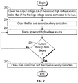
- FIG. 2 is a flow chart illustrating a method of connecting two high voltage DC sources to a bus in parallel according to one embodiment
- FIG. 3 is a schematic of a power bus that is initially driven by a first power source and to which a second power source (battery) is to be added in parallel.
- the power comes from the aircraft engine or aircraft power unit (APU) generally provides power to the DC bus.
- APU aircraft power unit
- a generator connects to the high pressure spool of a gas turbine engine via gear box. The power thus produced is connected to the DC bus of the aircraft.
- he proposed approach for and one HVDC source into parallel with another is to temporarily lower the voltage of the channel requesting to come on-line and use a pair of diodes and an auxiliary contactor to make the parallel connection while the voltage of the channel coming on line is ramped up.
- the natural commutation of the diodes connects the capacitors at the point(s) in time when their voltages are equal and thereby avoid a current spike.
- the main contactor is closed to provides paths around the diodes and the auxiliary contactors. At this time normal voltage and load division control is engaged.
- the auxiliary contactors carry modest current and only for a short time.
- FIG. 1 shows an example of bus 100 that includes a positive bus rail 102 and negative bus rail 104 .
- the terms positive and negative merely refer to the fact that the rails 102 , 104 can have a voltage differential.
- the positive rail 102 can be at +270V and the negative rail 104 can be a ⁇ 270V.
- these voltages could be +540V and 0V.
- the bus 100 is being driven by a first high voltage source 110 .
- the first high voltage source 110 includes a prime mover 112 that drives a first AC generator 114 .
- the prime mover 112 can be a spool of the gas turbine engine.
- the prime mover 112 is a high pressure spool of the gas turbine engine in one embodiment but can be other spools (e.g., low or medium) or can be an auxiliary power unit (APU) in one embodiment.
- the prime mover 112 can be connected to the first AC generator 114 by a gear box as is known in the art.
- the output of the first AC generator 114 is provided to a first rectifier 116 that converts the AC power received form the first AC generator 114 into a HVDC power.
- the first rectifier 116 produces a positive output (V+) on a first positive output line 120 and a negative output (V ⁇ ) on a first negative output line 122 .
- V+ positive output
- V ⁇ negative output
- first negative output line 122 This can be accomplished in any known manner including having two rectifiers, one of which is inverting.
- the first positive output line 120 and the first negative output line 122 are connected to the positive and negative bus rails 102 , 104 , respectively.
- First positive and negative smoothing capacitors 124 , 126 are connected between the first positive output line 120 and the first negative output line 122 , respectively, and ground to smooth the voltages provided on the first positive output line 120 and the first negative output line 122 (and thus, positive and negative bus rails 102 , 104 ).
- the first high voltage source 110 can be connected to the bus by one or more contactors 128 , 129 on the first positive output line 120 and the first negative output line 122 , respectively.
- the contactors 128 , 129 are shown as being closed.
- a bus coupling circuit 160 and method may allow the second high voltage source 130 to be added without creating a large current spike.
- the second high voltage source 130 is not connected to the bus 100 in FIG. 1 but based on the discussion herein, after the steps disclosed herein are performed, the second high voltage source 130 will be connected to the bus 100 in parallel with the first high voltage source 110 .
- the first and second high voltage sources can also be referred to as first and second high voltage direct current (HVDC) sources herein.
- the second high voltage source 130 includes a second prime mover 142 that drives a second AC generator 144 .
- the second prime mover 142 can be another spool of the gas turbine engine that is different than the first prime mover or can be an auxiliary power unit (APU).
- the second prime mover 142 can be connected to the second AC generator 144 by a gear box as is known in the art.
- the output of the second AC generator 144 is provided to a second rectifier 146 that converts the AC signal received form the second AC generator 144 into a HVDC signal. As shown, the second rectifier 146 produces a positive output (V+) on a second positive output line 150 and a negative output (V ⁇ ) on a second negative output line 152 .
- Second positive and negative smoothing capacitors 154 , 156 are connected between the second positive output line 150 and the second negative output line 152 , respectively, and ground to smooth the voltages provided on second positive output line 150 and the second negative output line 152 .
- bus coupling circuit 160 is connected between the second high voltage source 130 and the bus 100 .
- contactors 166 and 176 will couple the second positive output line 150 and the second negative output line 152 to the positive and negative bus rails 102 , 104 , respectively.
- the bus coupling circuit 160 includes positive line coupler 161 and a negative line coupler 171 that, respectively, are connected to the second positive output line 150 and the second negative output line 152 and the positive and negative bus rails 102 , 104 .
- Both the positive line coupler 161 and the negative line coupler 171 include main contactors that are connected in parallel to a serially connected diode/auxiliary contactor combination.
- the positive line coupler 161 includes a first auxiliary contactor 162 serially connected to a first diode 164 such that the diode 164 allows current flow from the second high voltage source 130 to the bus 100 but block a reverse flow of current (assuming the diode is not in reverse breakdown). The order of the two components can be reversed.
- a first main contactor 166 is connected in parallel with the first auxiliary contactor 162 /first diode 164 combination.
- negative positive line coupler 141 includes a first auxiliary contactor 162 serially connected to a second diode 174 such that the diode 164 allows current flow from the bus 100 to return to the second high voltage source 130 and such that is block a reverse flow of current (assume the diode is not in reverse breakdown). The order of the two components can be reversed.
- a second main contactor 176 is connected in parallel with the second auxiliary contactor 172 /second diode 174 combination.
- the output voltage out of the second high voltage source 130 is lowered so that it is below that of the first high voltage source 110 .
- This can include lowering the voltage so that the voltages across the second positive and negative smoothing capacitors 154 , 156 are below the voltages across the first positive and negative smoothing capacitors 124 , 126 .
- a controller 190 can be connected to voltage sensors (not shown) to perform this operation.
- the voltage of the second high voltage source 130 is ramped up. This ramping can continue until a current is detected through both the first and second diodes 164 , 174 as indicated by decision block 208 .
- This determination can be made by a controller 190 connected to one or more current sensors 192 , 194 that measure current through the first and second diodes.
- the current sensor 192 could measure current though both the diode and the switch in each line coupler 161 , 171 . That is, the current sensor could measure current through the first diode 162 and through the first main contactor 166 . In this manner, the sensors could also be sued for load division control after first main contactor 166 closes.
- the main contactors 166 and 176 are closed and the auxiliary contactors 162 , 172 can be opened as indicated at block 210 .
- the natural commutation of the first and second diodes 164 , 174 is used to connect the capacitors of each high voltage source 110 , 130 at the point(s) in time when their voltage is equal and thereby avoid a current spike.
- the main contactors 166 and 176 can each have two poles and be actuated by a single solenoid.
- the diodes are connected as shown in FIG. 1 . If the direction was reversed, rather than ramping voltage up, the voltage of the second high voltage source could be brought to level above that of the first and lowered until the diodes conduct. Such a configuration is shown in FIG. 3 . To distinguish, the reverse oriented diodes include a prime indication attached thereto. Thus, in one embodiment, in the system of FIG. 3 , the voltage across provided by the second high voltage source can be raised above that of the first high voltage source 110 and then lowered.
- the second high voltage source 130 includes a battery 143 rather than a prime mover/generator combination.
- the battery 143 could be replaced by the prime mover/generator combination of FIG. 1 .
- the battery 143 could replace the prime mover/generator combination in FIG. 1 .
- the voltage of the first power source 100 would be adjusted to connect the battery.
Abstract
Description
Claims (18)
Priority Applications (2)
| Application Number | Priority Date | Filing Date | Title |
|---|---|---|---|
| US16/532,683 US11011908B2 (en) | 2019-08-06 | 2019-08-06 | System and method for adding a high voltage DC source to a power bus |
| EP19216125.5A EP3772791B1 (en) | 2019-08-06 | 2019-12-13 | System and method for adding a high voltage dc source to a power bus |
Applications Claiming Priority (1)
| Application Number | Priority Date | Filing Date | Title |
|---|---|---|---|
| US16/532,683 US11011908B2 (en) | 2019-08-06 | 2019-08-06 | System and method for adding a high voltage DC source to a power bus |
Publications (2)
| Publication Number | Publication Date |
|---|---|
| US20210044107A1 US20210044107A1 (en) | 2021-02-11 |
| US11011908B2 true US11011908B2 (en) | 2021-05-18 |
Family
ID=68917324
Family Applications (1)
| Application Number | Title | Priority Date | Filing Date |
|---|---|---|---|
| US16/532,683 Active 2039-11-21 US11011908B2 (en) | 2019-08-06 | 2019-08-06 | System and method for adding a high voltage DC source to a power bus |
Country Status (2)
| Country | Link |
|---|---|
| US (1) | US11011908B2 (en) |
| EP (1) | EP3772791B1 (en) |
Cited By (1)
| Publication number | Priority date | Publication date | Assignee | Title |
|---|---|---|---|---|
| US20230251326A1 (en) * | 2022-02-09 | 2023-08-10 | Hamilton Sundstrand Corporation | System and method for input power detection of two power sources using single monitoring circuit |
Citations (16)
| Publication number | Priority date | Publication date | Assignee | Title |
|---|---|---|---|---|
| US6130813A (en) * | 1999-01-11 | 2000-10-10 | Dell U.S.A., L.P. | Protection circuit for electronic devices |
| US20070091528A1 (en) * | 2004-05-31 | 2007-04-26 | Denso Corporation | Inrush current limiting switching circuit for power supply |
| US20070268726A1 (en) | 2006-05-16 | 2007-11-22 | Honeywell International Inc. | Method and apparatus for integrated active-diode-oring and soft power switching |
| US20090224599A1 (en) * | 2008-03-06 | 2009-09-10 | Edwin Yue | Paralleled hvdc bus electrical power system architecture |
| US7595609B2 (en) * | 2006-03-09 | 2009-09-29 | Dell Products L.P. | Battery system power path configuration and methods for implementing same |
| CN102394557A (en) | 2011-09-06 | 2012-03-28 | 清华大学 | Hybrid parallel type high-voltage direct current traction power supply current transformer and control method thereof |
| US8237420B2 (en) * | 2010-02-26 | 2012-08-07 | Ambit Microsystems (Shanghai) Ltd. | Inrush current suppressing circuit and electronic device using the same |
| US20130329329A1 (en) * | 2012-06-11 | 2013-12-12 | Honeywell International Inc. | Solid state power control system for aircraft high voltage dc power distribution |
| US8723360B2 (en) | 2008-10-27 | 2014-05-13 | Rolls-Royce Plc | Distributed electrical generation system |
| US20140146582A1 (en) | 2012-11-29 | 2014-05-29 | General Electric Company | High voltage direct current (hvdc) converter system and method of operating the same |
| US9099936B2 (en) | 2013-03-14 | 2015-08-04 | General Electric Company | High voltage direct current (HVDC) converter system and method of operating the same |
| US20160322809A1 (en) | 2015-04-28 | 2016-11-03 | General Electric Company | Dc circuit breaker and method of use |
| WO2018130557A1 (en) | 2017-01-13 | 2018-07-19 | Siemens Aktiengesellschaft | Dc power switching assembly and method |
| US20180375327A1 (en) | 2017-06-27 | 2018-12-27 | Ge Aviation Systems, Llc | Solid state power contactor |
| US20190350105A1 (en) * | 2018-05-10 | 2019-11-14 | Microsoft Technology Licensing, Llc | Dc bus architecture for datacenters |
| US20200259360A1 (en) * | 2017-11-16 | 2020-08-13 | Murata Manufacturing Co., Ltd. | Power storage module and power supply system |
-
2019
- 2019-08-06 US US16/532,683 patent/US11011908B2/en active Active
- 2019-12-13 EP EP19216125.5A patent/EP3772791B1/en active Active
Patent Citations (16)
| Publication number | Priority date | Publication date | Assignee | Title |
|---|---|---|---|---|
| US6130813A (en) * | 1999-01-11 | 2000-10-10 | Dell U.S.A., L.P. | Protection circuit for electronic devices |
| US20070091528A1 (en) * | 2004-05-31 | 2007-04-26 | Denso Corporation | Inrush current limiting switching circuit for power supply |
| US7595609B2 (en) * | 2006-03-09 | 2009-09-29 | Dell Products L.P. | Battery system power path configuration and methods for implementing same |
| US20070268726A1 (en) | 2006-05-16 | 2007-11-22 | Honeywell International Inc. | Method and apparatus for integrated active-diode-oring and soft power switching |
| US20090224599A1 (en) * | 2008-03-06 | 2009-09-10 | Edwin Yue | Paralleled hvdc bus electrical power system architecture |
| US8723360B2 (en) | 2008-10-27 | 2014-05-13 | Rolls-Royce Plc | Distributed electrical generation system |
| US8237420B2 (en) * | 2010-02-26 | 2012-08-07 | Ambit Microsystems (Shanghai) Ltd. | Inrush current suppressing circuit and electronic device using the same |
| CN102394557A (en) | 2011-09-06 | 2012-03-28 | 清华大学 | Hybrid parallel type high-voltage direct current traction power supply current transformer and control method thereof |
| US20130329329A1 (en) * | 2012-06-11 | 2013-12-12 | Honeywell International Inc. | Solid state power control system for aircraft high voltage dc power distribution |
| US20140146582A1 (en) | 2012-11-29 | 2014-05-29 | General Electric Company | High voltage direct current (hvdc) converter system and method of operating the same |
| US9099936B2 (en) | 2013-03-14 | 2015-08-04 | General Electric Company | High voltage direct current (HVDC) converter system and method of operating the same |
| US20160322809A1 (en) | 2015-04-28 | 2016-11-03 | General Electric Company | Dc circuit breaker and method of use |
| WO2018130557A1 (en) | 2017-01-13 | 2018-07-19 | Siemens Aktiengesellschaft | Dc power switching assembly and method |
| US20180375327A1 (en) | 2017-06-27 | 2018-12-27 | Ge Aviation Systems, Llc | Solid state power contactor |
| US20200259360A1 (en) * | 2017-11-16 | 2020-08-13 | Murata Manufacturing Co., Ltd. | Power storage module and power supply system |
| US20190350105A1 (en) * | 2018-05-10 | 2019-11-14 | Microsoft Technology Licensing, Llc | Dc bus architecture for datacenters |
Non-Patent Citations (1)
| Title |
|---|
| European Search Report for Application No. 19216125.5, dated Jul. 20, 2020, 8 pages. |
Cited By (1)
| Publication number | Priority date | Publication date | Assignee | Title |
|---|---|---|---|---|
| US20230251326A1 (en) * | 2022-02-09 | 2023-08-10 | Hamilton Sundstrand Corporation | System and method for input power detection of two power sources using single monitoring circuit |
Also Published As
| Publication number | Publication date |
|---|---|
| US20210044107A1 (en) | 2021-02-11 |
| EP3772791A1 (en) | 2021-02-10 |
| EP3772791B1 (en) | 2023-09-13 |
Similar Documents
| Publication | Publication Date | Title |
|---|---|---|
| US9413264B2 (en) | Ground power unit for aircraft | |
| RU2467891C2 (en) | Method of feeding standby auxiliary consuming hardware, auxiliary converter and railway vehicle to this end | |
| CN107627860B (en) | External power supply device and method for realizing fireless loopback | |
| CN106208071B (en) | Hybrid AC and DC distribution system and method of use | |
| CN111033275B (en) | System for generating a power output and corresponding use | |
| US10910842B2 (en) | Systems and methods for providing electrical power to wind turbine components | |
| CN101903202A (en) | Arrangement for supplying devices of a locomotive with electric energy and method for operating said arrangement | |
| CN109421539A (en) | A kind of train rescuing power supply unit and its control method | |
| CN109327073A (en) | A kind of double dynamical power supply system | |
| US11011908B2 (en) | System and method for adding a high voltage DC source to a power bus | |
| CN107554299B (en) | Hybrid power source system of railway engineering machinery | |
| CN107650690B (en) | Control method for hybrid power source of railway engineering machinery | |
| US8264100B2 (en) | Electric power generating system for multiple sources and interface to an AC grid | |
| CN104603424A (en) | Electrical apparatus | |
| CN112600252A (en) | Multi-power supply parallel operation system and method for petroleum drilling machine | |
| SE524384C2 (en) | Electric power transmission system | |
| US11133672B1 (en) | System and method for adding a high voltage DC source to a power bus | |
| CN105978117A (en) | Storage battery charger | |
| CN202333829U (en) | Dynamic voltage restorer for 400-Hz medium-frequency power supply | |
| CN205319966U (en) | Vehicle auxiliary electrical power source power supply system | |
| US10658959B2 (en) | Power supply system with first and second AC voltage generators and respective 6-pulse rectifier units | |
| CN111756269A (en) | Passenger train DC power supply device | |
| CN207339706U (en) | A kind of aircraft power truck DC output voltage autocompensation installation | |
| CN111746592A (en) | Safe driving method and safe driving module for node-free three-phase alternating current point switch | |
| CN110401388A (en) | Generating set parallel connection control system and rail engineering automobile |
Legal Events
| Date | Code | Title | Description |
|---|---|---|---|
| FEPP | Fee payment procedure |
Free format text: ENTITY STATUS SET TO UNDISCOUNTED (ORIGINAL EVENT CODE: BIG.); ENTITY STATUS OF PATENT OWNER: LARGE ENTITY |
|
| AS | Assignment |
Owner name: HAMILTON SUNDSTRAND CORPORATION, NORTH CAROLINA Free format text: ASSIGNMENT OF ASSIGNORS INTEREST;ASSIGNOR:HARKE, MICHAEL C.;REEL/FRAME:050263/0913 Effective date: 20190806 Owner name: CLAVERHAM LTD., UNITED KINGDOM Free format text: ASSIGNMENT OF ASSIGNORS INTEREST;ASSIGNOR:HOPKINS, CHRISTOPHER E.;REEL/FRAME:050263/0818 Effective date: 20190808 Owner name: HAMILTON SUNDSTRAND CORPORATION, NORTH CAROLINA Free format text: ASSIGNMENT OF ASSIGNORS INTEREST;ASSIGNOR:CLAVERHAM LTD.;REEL/FRAME:050266/0393 Effective date: 20190902 |
|
| STPP | Information on status: patent application and granting procedure in general |
Free format text: NOTICE OF ALLOWANCE MAILED -- APPLICATION RECEIVED IN OFFICE OF PUBLICATIONS |
|
| STPP | Information on status: patent application and granting procedure in general |
Free format text: PUBLICATIONS -- ISSUE FEE PAYMENT RECEIVED |
|
| STPP | Information on status: patent application and granting procedure in general |
Free format text: PUBLICATIONS -- ISSUE FEE PAYMENT VERIFIED |
|
| STCF | Information on status: patent grant |
Free format text: PATENTED CASE |