US10908036B2 - Method and apparatus for less destructive evaluation and monitoring of a structure - Google Patents
Method and apparatus for less destructive evaluation and monitoring of a structure Download PDFInfo
- Publication number
- US10908036B2 US10908036B2 US14/250,266 US201414250266A US10908036B2 US 10908036 B2 US10908036 B2 US 10908036B2 US 201414250266 A US201414250266 A US 201414250266A US 10908036 B2 US10908036 B2 US 10908036B2
- Authority
- US
- United States
- Prior art keywords
- damage
- physical structure
- variable
- sizes
- simulated
- Prior art date
- Legal status (The legal status is an assumption and is not a legal conclusion. Google has not performed a legal analysis and makes no representation as to the accuracy of the status listed.)
- Active, expires
Links
- 238000000034 method Methods 0.000 title claims abstract description 46
- 238000012544 monitoring process Methods 0.000 title claims abstract description 43
- 230000001066 destructive effect Effects 0.000 title description 3
- 238000011156 evaluation Methods 0.000 title description 2
- 230000006378 damage Effects 0.000 claims abstract description 363
- 230000036541 health Effects 0.000 claims description 16
- 238000004088 simulation Methods 0.000 claims description 14
- 230000015654 memory Effects 0.000 claims description 9
- 238000012512 characterization method Methods 0.000 claims description 8
- 238000005259 measurement Methods 0.000 claims 4
- 238000004891 communication Methods 0.000 claims 1
- 230000006870 function Effects 0.000 description 8
- 230000008569 process Effects 0.000 description 7
- 238000012360 testing method Methods 0.000 description 7
- 230000000644 propagated effect Effects 0.000 description 5
- 230000008859 change Effects 0.000 description 4
- 238000009658 destructive testing Methods 0.000 description 4
- 239000000463 material Substances 0.000 description 4
- 239000000853 adhesive Substances 0.000 description 3
- 230000001070 adhesive effect Effects 0.000 description 3
- 230000001902 propagating effect Effects 0.000 description 3
- 230000008439 repair process Effects 0.000 description 3
- 238000004458 analytical method Methods 0.000 description 2
- 238000001514 detection method Methods 0.000 description 2
- 238000012986 modification Methods 0.000 description 2
- 230000004048 modification Effects 0.000 description 2
- 229910000831 Steel Inorganic materials 0.000 description 1
- 238000013459 approach Methods 0.000 description 1
- 230000006399 behavior Effects 0.000 description 1
- 230000008901 benefit Effects 0.000 description 1
- 239000003990 capacitor Substances 0.000 description 1
- 239000002131 composite material Substances 0.000 description 1
- 238000010276 construction Methods 0.000 description 1
- 230000032798 delamination Effects 0.000 description 1
- 238000010586 diagram Methods 0.000 description 1
- 238000009661 fatigue test Methods 0.000 description 1
- 229910001095 light aluminium alloy Inorganic materials 0.000 description 1
- 238000007620 mathematical function Methods 0.000 description 1
- 230000004044 response Effects 0.000 description 1
- 239000010959 steel Substances 0.000 description 1
Images


Classifications
-
- G—PHYSICS
- G01—MEASURING; TESTING
- G01L—MEASURING FORCE, STRESS, TORQUE, WORK, MECHANICAL POWER, MECHANICAL EFFICIENCY, OR FLUID PRESSURE
- G01L1/00—Measuring force or stress, in general
- G01L1/16—Measuring force or stress, in general using properties of piezoelectric devices
-
- G—PHYSICS
- G01—MEASURING; TESTING
- G01M—TESTING STATIC OR DYNAMIC BALANCE OF MACHINES OR STRUCTURES; TESTING OF STRUCTURES OR APPARATUS, NOT OTHERWISE PROVIDED FOR
- G01M5/00—Investigating the elasticity of structures, e.g. deflection of bridges or air-craft wings
- G01M5/0033—Investigating the elasticity of structures, e.g. deflection of bridges or air-craft wings by determining damage, crack or wear
-
- G—PHYSICS
- G01—MEASURING; TESTING
- G01M—TESTING STATIC OR DYNAMIC BALANCE OF MACHINES OR STRUCTURES; TESTING OF STRUCTURES OR APPARATUS, NOT OTHERWISE PROVIDED FOR
- G01M5/00—Investigating the elasticity of structures, e.g. deflection of bridges or air-craft wings
- G01M5/0066—Investigating the elasticity of structures, e.g. deflection of bridges or air-craft wings by exciting or detecting vibration or acceleration
Definitions
- Embodiments of the invention relate generally to structural health monitoring. More specifically, embodiments of the invention relate to methods and apparatuses for the less destructive evaluation and monitoring of structures.
- Embodiments of the invention can be implemented in a number of ways, including as a method, as an apparatus, and as a computer-readable medium.
- a structural health monitoring method comprises: for a second structure representative of a first structure, determining a first relationship between sizes of simulated damage on the second structure and values of a damage index determined for the simulated damage. Also included is determining a second relationship between sizes of actual damage to the second structure and values of the damage index determined for the actual damage. From the first and second relationships, a third relationship is determined between the sizes of actual damage to the second structure and the sizes of simulated damage on the second structure. A fourth relationship is also determined between sizes of simulated damage on the first structure and values of the damage index determined for the simulated damage on the first structure.
- the method may further include monitoring the first structure so as to determine at least one value of the damage index for actual damage to the first structure; and substituting the at least one value of the damage index for actual damage to the first structure for the corresponding values of the damage index determined for the simulated damage of the fourth relationship, so as to determine corresponding values of the sizes of simulated damage on the first structure. Also included may be substituting the corresponding values of the sizes of simulated damage on the first structure for the corresponding values of the sizes of simulated damage on the second structure of the third relationship, so as to determine corresponding values of the sizes of actual damage to the second structure, and so as to thereby approximate the corresponding values of the sizes of actual damage to the second structure as one or more sizes of the actual damage to the first structure.
- the simulated damage on the second structure may comprise damage simulators of differing sizes, each coupled to the second structure.
- the simulated damage on the first structure may comprise damage simulators of differing sizes, each coupled to the first structure.
- the damage simulators may comprise rigid devices each having a first elongated flat side having a first length representing a length of a simulated crack, the flat side having a pointed end representing a tip of the simulated crack.
- the first relationship may be a first curve fit to the sizes of simulated damage on the second structure; the second relationship may be a second curve fit to the sizes of actual damage to the second structure; the third relationship may be a third curve fit to the sizes of actual damage to the second structure; and the fourth relationship may be a fourth curve fit to the sizes of simulated damage on the first structure.
- At least one of the first, second, third, and fourth curves may be a first degree polynomial.
- At least one of the first, second, third, and fourth curves may be a power curve.
- the method may further comprise determining a minimum size from among the sizes of simulated damage on the first structure, the minimum size being a threshold damage size below which a corresponding size of actual damage to the first structure is disregarded.
- a method of monitoring a first structure at least partially according to properties of a second structure may comprise: determining a first relationship between a first variable and a second variable, wherein the first variable represents sizes of actual damage to the second structure, and the second variable represents sizes of simulated damage on the second structure.
- the method may also include determining a second relationship between a third variable and a fourth variable, wherein the third variable represents sizes of simulated damage on the first structure, and the fourth variable represents values of a damage index determined for the simulated damage on the first structure; and determining an estimate of damage to the first structure according to the first and second relationships.
- the determining an estimate of damage to the first structure may further comprise: approximating values of the damage index determined from a monitoring of the first structure as corresponding values of the fourth variable, so as to determine from the second relationship corresponding values of the third variable; approximating the corresponding values of the third variable as corresponding values of the second variable, so as to determine from the first relationship corresponding values of the first variable; and approximating the corresponding values of the first variable as sizes of actual damage to the first structure.
- the simulated damage on the second structure may comprise damage simulators of differing sizes, each coupled to the second structure; and wherein the simulated damage on the first structure comprises damage simulators of differing sizes, each coupled to the first structure.
- the damage simulators may comprise rigid devices each having a first elongated flat side having a first length representing a length of a simulated crack, the flat side having a pointed end representing a tip of the simulated crack.
- the method may further comprise determining a minimum size from among the sizes of simulated damage on the first structure, the minimum size being a threshold damage size below which a corresponding size of actual damage to the first structure is disregarded.
- a structural health monitoring system for monitoring a first structure at least partially according to properties of a second structure comprises: a controller; and one or more memories storing data corresponding to a first relationship between a first variable and a second variable, and a second relationship between a third variable and a fourth variable.
- the first variable represents sizes of actual damage to the second structure
- the second variable represents sizes of simulated damage on the second structure.
- the third variable represents sizes of simulated damage on the first structure
- the fourth variable represents values of a damage index determined for the simulated damage on the first structure.
- the controller is configured to determine an estimate of actual damage to the first structure according to the stored data corresponding to the first and second relationships.
- the controller may be further configured to: approximate values of the damage index determined from a monitoring of the first structure as corresponding values of the fourth variable, so as to determine from the second relationship corresponding values of the third variable; approximate the corresponding values of the third variable as corresponding values of the second variable, so as to determine from the first relationship corresponding values of the first variable; and approximate the corresponding values of the first variable as sizes of actual damage to the first structure.
- the one or more memories may further store a minimum size from among the sizes of simulated damage on the first structure, the minimum size being a threshold damage size below which a corresponding size of the estimated actual damage to the first structure is disregarded.
- one or more non-transitory computer-readable memories collectively store data and collectively further store instructions for carrying out a method.
- the data comprises data corresponding to a first relationship between a first variable and a second variable, and a second relationship between a third variable and a fourth variable; and the method comprises determining an estimate of actual damage to the first structure according to the stored data corresponding to the first and second relationships.
- the first variable represents, for a first structure representative of a second structure, sizes of actual damage to the second structure, and the second variable represents sizes of simulated damage on the second structure.
- the third variable represents sizes of simulated damage on the first structure, and the fourth variable represents values of a damage index determined for the simulated damage on the first structure.
- the method may further comprise: approximating values of the damage index determined from a monitoring of the first structure as corresponding values of the fourth variable, so as to determine from the second relationship corresponding values of the third variable; approximating the corresponding values of the third variable as corresponding values of the second variable, so as to determine from the first relationship corresponding values of the first variable; and approximating the corresponding values of the first variable as sizes of actual damage to the first structure.
- the data may further comprise data corresponding to a minimum size from among the sizes of simulated damage on the first structure, the minimum size being a threshold damage size below which a corresponding estimated size of actual damage to the first structure is disregarded.
- FIGS. 1A-1C illustrate an exemplary sensor system that can be used in conjunction with embodiments of the present invention.
- FIG. 2 is a flowchart illustrating process steps taken in accordance with embodiments of the present invention.
- FIG. 3 illustrates a conceptual damage simulator and actual damage simulators constructed in accordance with embodiments of the present invention.
- FIG. 4 is a graph conceptually illustrating threshold determination in accordance with embodiments of the present invention.
- a method and apparatus which allows for accurate monitoring and damage characterization without requiring damage to the structure in question. More specifically, embodiments of the invention acquire information about how the structure is affected by damage, without first damaging the structure. A coupon, or replica of the structure, is subjected to both simulated and actual damage instead. In addition, damage simulators are applied to the real structure. The performance of the coupon when subjected to damage (both real and simulated), as well as the performance of the real structure with simulated damage, is used to infer the performance of the real structure when undergoing actual damage.
- Embodiments of the invention can employ any sensors, such as piezoelectric (PZT) transducer s capable of both generating and detecting stress waves in a structure.
- PZT piezoelectric
- FIG. 1A shows a flexible sensing layer that can be used in accordance with embodiments of the present invention.
- a diagnostic layer 100 is shown, which contains an array of sensors 102 .
- the sensors 102 can be any sensors capable of generating and receiving signals used in structural health monitoring such as stress waves, and are connected to conductive traces 104 .
- the traces 104 connect (or interconnect, if necessary) sensors 102 to one or more output leads 106 configured for connection to a processor or other device capable of analyzing the data derived from the sensors 102 .
- the diagnostic layer 100 and its operation are known, and are further described in U.S. Pat. No. 6,370,964 to Chang et al., which is hereby incorporated by reference in its entirety and for all purposes. Construction of the diagnostic layer 100 is also explained in U.S. Pat. No. 7,413,919 to Qing et al., which is also incorporated by reference in its entirety and for all purposes. It should be noted that the present invention is not limited to the embodiments disclosed in the aforementioned U.S. Pat. No. 7,413,919, but instead encompasses the use of flexible sensor layers having any configuration. For illustration, FIG. 1B further describes aspects of the operation of the diagnostic layer 100 .
- the output leads 106 are electrically connected to an analysis unit such as a microprocessor 108 , suitable for analyzing signals from the sensors 102 .
- the flexible layer 100 is first attached to a structure in a manner that allows the sensing elements 102 to detect quantities related to the health of the structure.
- the sensors 102 can be sensors configured to detect stress waves propagated within the structure, and emit electrical signals accordingly.
- the microprocessor 108 analyzes these electrical signals to assess various aspects of the health of the structure. For instance, detected stress waves can be analyzed to detect crack propagation within the structure, delamination within composite structures, or the likelihood of fatigue-related failure. Quantities such as these can then be displayed to the user via display 110 .
- the sensors 102 can be piezoelectric transducers capable of reacting to a propagating stress wave by generating a voltage signal. Analysis of these signals highlights properties of the stress wave, such as its magnitude, propagation speed, frequency components, and the like. Such properties are known to be useful in structural health monitoring.
- FIG. 1C illustrates a circuit diagram representation of such an embodiment. This embodiment can often be represented as a circuit 112 , where each sensor 102 is represented as a voltage source 114 in series with a capacitor 116 (impedance circuitry) used to adjust signal strength.
- This pair is in electrical contact with a data acquisition unit 118 , such as a known data acquisition card employed by microprocessors 108 (the data acquisition unit 118 can be thought of as a component interface to the microprocessor 108 ).
- Propagating stress waves induce the sensor 102 to emit a voltage signal that is recorded by the data acquisition unit 118 , where it can be analyzed to determine the health of the structure in question.
- These piezoelectric transducers can also act as actuators, converting an applied voltage to a stress wave signal.
- FIG. 2 is a flowchart illustrating process steps taken in accordance with embodiments of the present invention.
- the process starts by fabricating a representative structural “coupon” (Step 200 ).
- the coupon is a simulation of a particular part of the “real” structure that is to be monitored.
- the “real” structure of interest is a helicopter, as shown at the top of FIG. 2 .
- the area to be monitored is a portion of the helicopter's tail, as shown.
- the coupon would then be a mock-up or simulation of that portion of the tail, made of the same or similar materials and having similar shape, dimensions, and features. It would therefore have the same or similar structural properties, and damage to the coupon would thus likely exhibit the same or similar characteristics as the same damage inflicted upon the real structure (i.e., the helicopter).
- monitoring signals such as stress waves can be propagated through the undamaged structure by certain sensors 102 , and subsequently detected by other sensors 102 .
- the characteristics of the detected stress waves thus indicate what the monitoring signals look like after they have propagated through the undamaged structure. They thus can be considered baseline signals, representative of a baseline or undamaged state of the structure. Characteristics of these signals can therefore be stored as baseline signal information, and used as a reference point. Later signals can be compared to these baseline signals, where differences from baseline signals indicate a change in the structure such as damage.
- a diagnostic layer 100 is attached to the coupon, and baseline testing of various locations on the coupon is then performed (Step 202 ).
- This baseline testing can include propagating stress waves through locations of the coupon, detecting the propagated stress waves at sensors 102 of diagnostic layer 100 , and storing the detected waveforms as baseline signals.
- Embodiments of the invention contemplate the use of any type and shape of signals, sent from any suitable signal generator, and the storage of the resulting detected waveforms in any manner for comparison to subsequent monitoring signals.
- Damage simulators are applied to the coupon, to simulate damage thereto (Step 204 ).
- Damage simulators are known, and one type of damage simulator suitable for use with embodiments of the invention is further described below in connection with FIG. 3 .
- Damage simulators typically represent damage of a particular size and shape, such as a crack of a particular length. Accordingly, damage simulators can be placed at any locations on the coupon where damage to the corresponding real structure may be expected to occur. For instance, damage simulators representing cracks may be placed and oriented radially outward from a screw hole, or placed to represent cracks emanating from a notch or other stress concentrator.
- Embodiments of the invention contemplate the placement of damage simulators of any size, at any location on a coupon, so that the signals corresponding to any kind of simulated damage may be recorded and used in monitoring for real damage.
- the diagnostic layer 100 generates stress waves, or monitoring signals, within the structure, where they are detected by certain sensors 102 after the waves pass through regions occupied by the damage simulators.
- the sensors 102 are preferably located in the same positions as those that collected baseline information, for accurate comparison of data.
- the detected stress waves are then compared to the stored baseline stress wave shapes determined from Step 202 , with differences between the detected stress waves and the baseline stress waves representing the degree of damage due to the sizes and orientations of the damage simulators used.
- This comparison can be performed in any manner that can be used in subsequent damage detection.
- One such approach involves determining values of a damage index DI from the signal comparisons, and plotting the corresponding damage simulator size values on a graph of damage size versus DI. That is, for each individual damage simulator, stress waves are passed through that particular region of the coupon, and the resulting detected stress waves are compared to previously-determined baseline stress waveforms for that same region of the coupon without the damage simulator. A DI value is then determined from this comparison, and the process is repeated for each damage simulator.
- Successive tests can be performed for a single location on the coupon, with the previous simulator removed and a differently-sized simulator applied for each test. For multiple damage simulators of different sizes, this results in a graph of damage size versus DI for simulated damage to one location on the coupon. Multiple such locations can be tested in this manner, to produce a graph for each location on the coupon.
- Embodiments of the invention contemplate the determination of DI values in any manner.
- One nonlimiting example involves determining DI values according to the following:
- the DI values calculated from Equations (1) can be plotted along with their corresponding damage simulator sizes to produce a graph of damage size versus DI, which represents damage size as a function of DI for simulated damage to the coupon (Step 206 ).
- This function can be seen as the lower curve of the topmost graph of FIG. 2 , i.e. curve SIM in the uppermost graph of FIG. 2 .
- Step 208 the damage simulators are removed from the coupon.
- the process of Step 206 is then repeated without the damage simulators, and with actual damage applied to the coupon. That is, the coupon is damaged, and a plot of damage size versus DI for actual damage to the coupon is determined (Step 210 ). More specifically, actual damage is inflicted upon the coupon, in the same locations and having the same damage sizes and orientations as represented by the damage simulators.
- the diagnostic layer 100 then passes stress waves through the areas of actual damage, which alters the stress waves.
- the SIM and ACT curves for the various coupon locations are then used to determine a curve of size of actual damage to the coupon versus the size of simulated damage to the coupon at each location (Step 212 ).
- the corresponding damage size values of the SIM and ACT curves are plotted on a graph of damage size of actual damage (DS ACT ) vs. damage size of simulated damage (DS SIM ).
- the resulting curve, or collection of data points represents the relationship between actual damage size and simulated damage size for the coupon. That is, for each size of simulated damage to a particular location on the coupon, how much larger (or smaller) the corresponding actual damage to the coupon will be. This relationship is represented by the graph to the right of Step 212 in FIG. 2 .
- Baseline testing of the actual structure to be monitored is then performed (Step 214 ).
- This baseline testing can be performed in similar manner to that of Step 202 , such as by applying a diagnostic layer 100 to the actual structure so that sensors 102 are located in corresponding locations as those placed on the coupon during Step 202 .
- Stress waveforms are then passed through various portions of the actual structure, received at various sensors 102 , and stored to serve as baseline waveforms for particular locations on the real structure.
- signals from subsequent monitoring of the actual structure can then be compared to these stored baseline waveforms, with differences indicating changes, such as damage, to particular locations on the structure.
- damage simulators are then applied to the actual structure (Step 216 ). These damage simulators are of the same size as those used in Step 204 , and are placed in the same locations and orientations as those placed on the coupon in Step 204 .
- the actual structure is then tested to determine its response to simulated damage (Step 218 ).
- the sensors 102 generate stress waveforms within the structure, and also detect these same stress waves after they have propagated through the areas occupied by the damage simulators.
- the detected stress waves and the stored baseline waveforms of Step 214 are then used in connection with Equations (1) to determine plots of damage size versus DI for simulated damage to locations on the actual structure.
- the relationship between damage size and DI is determined for simulated damage to locations on the actual structure. This is represented, for one location, by the graph to the right of Step 218 in FIG. 2 .
- a curve can be fit to the relationship of Step 218 , similar to the ACT and SIM curves, and/or the curve of Step 212 , above. Also as above, this curve can be any curve, linear or otherwise. Alternatively, no curve need be fitted to the data.
- Steps 212 and 218 are then used in real-time monitoring of the actual structure to detect the occurrence of damage thereto.
- the damage simulators are removed from the actual structure, and at any subsequent time, the structure can be monitored to detect the possible presence of damage (Step 220 ). This monitoring can be at any time, e.g. during, before, or after operation, or the like.
- the diagnostic layer 100 is employed to transmit the same stress waveforms through the structure once again, and Equations (1) are used to determine, from the resulting detected stress waveforms and stored baseline waveform data, DI values corresponding to the current state of the actual structure.
- Step 222 These DI values are then used to determine corresponding damage size values according to the relation from Step 218 , e.g., the graph exemplified to the right of Step 218 in FIG. 2 (Step 222 ). More specifically, the graph of Step 218 describes the relationship between damage size and damage index for simulated damage to the real structure. By assuming that the measured DI values from Step 220 are approximately equal to the same DI values determined from simulated damage to the real structure, the graph of Step 218 can then be used to determine corresponding simulated damage size values for that same structure.
- the DS SIM R values determined at Step 222 are then used to determine corresponding actual damage size values according to the relation from Step 212 , e.g., the graph exemplified to the right of Step 212 in FIG. 2 (Step 224 ).
- the graph of Step 212 describes the relationship between actual damage size and simulated damage size for the coupon.
- the relation of Step 212 can be used to determine the size of actual damage which corresponds to the simulated damage determined at Step 222 .
- the result of Step 224 is a set of damage sizes, DS ACT C , corresponding to the measured DI values determined from the real structure.
- embodiments of the invention determine two relationships.
- the first is the relationship between simulated and actual damage size for the coupon, i.e. for the coupon, the size of actual damage that any given simulated damage size represents.
- the second is the relationship between simulated damage size and simulated damage index for the real structure, i.e. for the real structure, the simulated damage size corresponding to a particular DI value.
- the real structure is analyzed to determine the relationship between DI and corresponding simulated damage size
- the coupon is analyzed to determine the relationship between simulated damage size and actual damage size. If the sizes of simulated damage applied to the real structure are the same as the sizes of simulated damage applied to the coupon, then the output of the second relationship is equal to the input of the first relationship.
- the two relationships together create a relationship between damage index values for simulated damage to the real structure, and the size of actual damage to the coupon. Therefore, by assuming that measured damage index values for actual damage to the structure are approximately equal to the corresponding DI values for simulated damage to the real structure (i.e. that simulated damage to the real structure influences stress waveforms in the same manner as actual damage to the real structure), and by further assuming that the coupon responds to damage in the same manner as the real structure, the damage size predicted by the two relationships is an accurate prediction of the size of the actual damage to the real structure.
- This allows the two relationships to serve as a mathematical function of sorts, with the input being DI values measured from the real structure, and the output being the size of corresponding damage.
- the two relationships thus allow for real-time damage assessment, with the processor 108 measuring DI values for the real structure, and the relationships determining a corresponding damage size.
- the only actual damage done to any structure in the formulating of the above two relationships is damage done to the coupon, at Step 210 .
- the real structure itself is not damaged—rather, only simulated damage is applied.
- the real structure is used to determine the relationship between DI and simulated damage size, while the coupon is used to determine the relationship between simulated damage size and actual damage size.
- embodiments of the invention allow for damage to the real structure to be characterized without requiring any actual damage to the real structure.
- the only actual damage is to the coupon, a replica of a portion of the structure. In this manner, characterization of the real structure can be accomplished in less destructive fashion. This in turn may result in significant savings of time and money, as no repairs need be made to the structure, and the coupon may typically be fabricated quicker and cheaper, and may simply be disposed of after testing.
- FIG. 2 illustrates methods of the invention applied to a helicopter tail, with the corresponding coupon being sized and shaped as the portion of the tail that is of interest.
- the coupon would thus be made of the same material, e.g. aircraft aluminum or steel, and having the same thickness and curvature as the tail.
- the coupon would also have rivets or bolts located in the same locations as those on the tail.
- many different damage simulators may be used.
- Embodiments of the invention contemplate any damage simulator capable of accurately simulating damage to a structure.
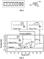
- FIG. 3 illustrates one such exemplary damage simulator.
- a damage simulator 300 has a metallic, wedge like or elongated body with a substantially flat face 302 that can be applied to a structure such as by a removable adhesive.
- damage simulator 300 is configured to simulate a crack. As such, it has a pointed end 304 simulating a crack tip, and the face 302 is generally linear and elongated to simulate the overall shape of a crack.
- FIG. 3 also shows examples of different-sized damage simulators, to be used for simulating different-sized cracks. The simulated crack length is written in mm on an upper face of each damage simulator.
- the damage simulator 300 can be removably applied to the surface of a structure, such as with a removable adhesive. Any adhesive is contemplated, although AquaBond® 55 can be used as one example. When applied to the surface of a structure (such as a real structure or its corresponding coupon), the damage simulator 300 constrains the surface of the structure, altering any stress waves that may pass through that region of the structure's surface in a manner similar to that of an actual crack. Other geometries, materials, and types of damage simulators 300 are contemplated for simulation of other types of damage.
- the process can include the determination of a minimum damage size, or threshold value below which damage is not determined. That is, at Step 222 , if it is determined that the detected DI value corresponds to a size of damage that is below the threshold value, the corresponding damage is considered to be too small to be of concern, and disregarded, so that the process can stop at Step 222 , or alternatively may continue but with the final results being discarded.
- the determination of this threshold value may be made in any manner. For instance, the real structure or the coupon may be tested to determine the size at which damage begins to be of concern, as decided in any manner.
- FIG. 4 illustrates one such example of threshold damage size determination.
- crack length as a function of fatigue cycles is shown in the graph of FIG. 4 . From this graph, it can be seen that crack length (as measured by corresponding DI value) remains relatively stable until approximately 45K cycles, at which point the crack begins to grow. Accordingly, the threshold value is set at the critical crack length beyond which cracks tend to grow with further stress cycles. This point is shown as the dotted line in FIG. 4 , corresponding to a crack size of just less than 1 mm and a damage index value of just over 0.1. In operation then, any measured DI values resulting in a DS SIM R value below this threshold number can be disregarded.
- any relationships between damage index and damage size are contemplated, and these relationships can be of any form.
- the relationships can be any function fit to the corresponding data, such as any linear or nonlinear function.
- the relationship can simply be a set of data points, with intermediate values determined by interpolation or by any other suitable manner if desired.
- any coupon type and geometry is contemplated, so long as it is representative of its corresponding real structure.
- any damage simulator is contemplated, of any material and geometry, for simulating any type of damage.
- the embodiments were chosen and described in order to best explain the principles of the invention and its practical applications, to thereby enable others skilled in the art to best utilize the invention and various embodiments with various modifications as are suited to the particular use contemplated.
- the various features of the disclosed embodiments and examples may be mixed and matched in any manner or combination to form further embodiments contemplated by the invention.
Abstract
Description
where
Claims (19)
Priority Applications (1)
| Application Number | Priority Date | Filing Date | Title |
|---|---|---|---|
| US14/250,266 US10908036B2 (en) | 2013-04-12 | 2014-04-10 | Method and apparatus for less destructive evaluation and monitoring of a structure |
Applications Claiming Priority (2)
| Application Number | Priority Date | Filing Date | Title |
|---|---|---|---|
| US201361811664P | 2013-04-12 | 2013-04-12 | |
| US14/250,266 US10908036B2 (en) | 2013-04-12 | 2014-04-10 | Method and apparatus for less destructive evaluation and monitoring of a structure |
Publications (2)
| Publication Number | Publication Date |
|---|---|
| US20140309950A1 US20140309950A1 (en) | 2014-10-16 |
| US10908036B2 true US10908036B2 (en) | 2021-02-02 |
Family
ID=51687362
Family Applications (1)
| Application Number | Title | Priority Date | Filing Date |
|---|---|---|---|
| US14/250,266 Active 2036-09-19 US10908036B2 (en) | 2013-04-12 | 2014-04-10 | Method and apparatus for less destructive evaluation and monitoring of a structure |
Country Status (1)
| Country | Link |
|---|---|
| US (1) | US10908036B2 (en) |
Families Citing this family (2)
| Publication number | Priority date | Publication date | Assignee | Title |
|---|---|---|---|---|
| US10458954B2 (en) * | 2016-09-15 | 2019-10-29 | Kabushiki Kaisha Toshiba | Structure evaluation system, structure evaluation apparatus, and structure evaluation method |
| US10352912B2 (en) | 2016-09-15 | 2019-07-16 | Kabushiki Kaisha Toshiba | Structure evaluation system, structure evaluation apparatus, and structure evaluation method |
Citations (10)
| Publication number | Priority date | Publication date | Assignee | Title |
|---|---|---|---|---|
| US5816530A (en) * | 1996-10-09 | 1998-10-06 | Northrop Grumman Corporation | Structural life monitoring system |
| US6006163A (en) * | 1997-09-15 | 1999-12-21 | Mcdonnell Douglas Corporation | Active damage interrogation method for structural health monitoring |
| US6370964B1 (en) | 1998-11-23 | 2002-04-16 | The Board Of Trustees Of The Leland Stanford Junior University | Diagnostic layer and methods for detecting structural integrity of composite and metallic materials |
| US20070265790A1 (en) * | 2006-05-09 | 2007-11-15 | Lockheed Martin Corporation | System to monitor the health of a structure, program product and related methods |
| US7413919B2 (en) | 2003-06-20 | 2008-08-19 | Acellent Technologies, Inc. | Method of manufacturing a structural health monitoring layer |
| US20110040496A1 (en) * | 2009-08-13 | 2011-02-17 | Banerjee Sourav | Method and apparatus for estimating damage in a structure |
| US20120271824A1 (en) * | 2011-04-19 | 2012-10-25 | Jentek Sensors, Inc. | Performance Curve Generation For Non-Destructive Testing Sensors |
| US20140058709A1 (en) * | 2011-02-28 | 2014-02-27 | Critical Materials, Lda. | Structural health management system and method based on combined physical and simulated data |
| US20140100832A1 (en) * | 2012-10-09 | 2014-04-10 | The Boeing Company | Methods and systems for structural health monitoring |
| US20170108402A1 (en) * | 2014-03-26 | 2017-04-20 | Sikorsky Aircraft Corporation | Fracture mechanics based method for composite damage tolerance criteria |
-
2014
- 2014-04-10 US US14/250,266 patent/US10908036B2/en active Active
Patent Citations (10)
| Publication number | Priority date | Publication date | Assignee | Title |
|---|---|---|---|---|
| US5816530A (en) * | 1996-10-09 | 1998-10-06 | Northrop Grumman Corporation | Structural life monitoring system |
| US6006163A (en) * | 1997-09-15 | 1999-12-21 | Mcdonnell Douglas Corporation | Active damage interrogation method for structural health monitoring |
| US6370964B1 (en) | 1998-11-23 | 2002-04-16 | The Board Of Trustees Of The Leland Stanford Junior University | Diagnostic layer and methods for detecting structural integrity of composite and metallic materials |
| US7413919B2 (en) | 2003-06-20 | 2008-08-19 | Acellent Technologies, Inc. | Method of manufacturing a structural health monitoring layer |
| US20070265790A1 (en) * | 2006-05-09 | 2007-11-15 | Lockheed Martin Corporation | System to monitor the health of a structure, program product and related methods |
| US20110040496A1 (en) * | 2009-08-13 | 2011-02-17 | Banerjee Sourav | Method and apparatus for estimating damage in a structure |
| US20140058709A1 (en) * | 2011-02-28 | 2014-02-27 | Critical Materials, Lda. | Structural health management system and method based on combined physical and simulated data |
| US20120271824A1 (en) * | 2011-04-19 | 2012-10-25 | Jentek Sensors, Inc. | Performance Curve Generation For Non-Destructive Testing Sensors |
| US20140100832A1 (en) * | 2012-10-09 | 2014-04-10 | The Boeing Company | Methods and systems for structural health monitoring |
| US20170108402A1 (en) * | 2014-03-26 | 2017-04-20 | Sikorsky Aircraft Corporation | Fracture mechanics based method for composite damage tolerance criteria |
Non-Patent Citations (2)
| Title |
|---|
| Choi et al., "Nondestructive damage detection in structures using changes in compliance", International Journal of Solids and Structures 42, pp. 4494-4513 (2005). * |
| Viana, Julio C. et al., "Combining Experimental and Computed Data for Effective SHM of Critical Structural Components," IEEEEAC paper#1360 pp. 1-10 (2011) (Year: 2011). * |
Also Published As
| Publication number | Publication date |
|---|---|
| US20140309950A1 (en) | 2014-10-16 |
Similar Documents
| Publication | Publication Date | Title |
|---|---|---|
| US7881881B2 (en) | Structural health monitoring apparatus and methodology | |
| Croxford et al. | Efficient temperature compensation strategies for guided wave structural health monitoring | |
| Konstantinidis et al. | An investigation into the temperature stability of a guided wave structural health monitoring system using permanently attached sensors | |
| EP2720024A2 (en) | Methods and systems for structural health monitoring | |
| CN107014668A (en) | A kind of fatigue crack integrated monitoring based on piezoelectricity and smart coat sensor | |
| US10466204B2 (en) | Welding state inspection method | |
| EP3480455B1 (en) | Wind turbine monitoring device, wind turbine monitoring method, wind turbine monitoring program, and storage medium | |
| US7620503B2 (en) | Signal processing fault detection system | |
| US9176025B2 (en) | Apparatus and method of vibration testing for manufacturing defect detection in composite insulators | |
| CN106949861A (en) | A kind of method that non-linear ultrasonic monitors metal material strain variation on-line | |
| Light-Marquez et al. | Structural damage identification in wind turbine blades using piezoelectric active sensing | |
| US10908036B2 (en) | Method and apparatus for less destructive evaluation and monitoring of a structure | |
| CN106767475A (en) | A kind of hole-edge crack diagnostic method that fiber grating spectral image analysis are pasted based on horizontal cloth | |
| Rokhlin et al. | In situ ultrasonic measurement of crack closure | |
| Mandache et al. | Considerations on structural health monitoring reliability | |
| KR102157903B1 (en) | System and method for warning of fatigue crack failure based on nonlinear ultrasonic modulation, and system and method for estimating residual life of structure using the same | |
| Su et al. | Nonlinear ultrasonics for health monitoring of aerospace structures using active sparse sensor networks | |
| EP3126825B1 (en) | Method and device for inspection of solids by means of ultrasound | |
| Ihn et al. | Multicrack growth monitoring at riveted lap joints using piezoelectric patches | |
| EP3078967A1 (en) | A system and a method for detecting damage | |
| Haldar et al. | Data analysis challenges in structural health assessment using measured dynamic responses | |
| Bao et al. | Linear and nonlinear finite element simulation of wave propagation through bolted lap joint | |
| CN108828011A (en) | A kind of impedance modulation damage detecting method of fatigue crack | |
| He et al. | A novel crack size quantification method based on lamb wave simulation | |
| US11624687B2 (en) | Apparatus and method for detecting microcrack using orthogonality analysis of mode shape vector and principal plane in resonance point |
Legal Events
| Date | Code | Title | Description |
|---|---|---|---|
| AS | Assignment |
Owner name: ACELLENT TECHNOLOGIES, INC., CALIFORNIA Free format text: ASSIGNMENT OF ASSIGNORS INTEREST;ASSIGNORS:JANAPATI, VISHNUVARDHAN;LEE, SANG JUN;CHANG, FU-KUO;AND OTHERS;REEL/FRAME:032660/0357 Effective date: 20140410 |
|
| FEPP | Fee payment procedure |
Free format text: ENTITY STATUS SET TO SMALL (ORIGINAL EVENT CODE: SMAL); ENTITY STATUS OF PATENT OWNER: SMALL ENTITY |
|
| STPP | Information on status: patent application and granting procedure in general |
Free format text: FINAL REJECTION MAILED |
|
| STPP | Information on status: patent application and granting procedure in general |
Free format text: DOCKETED NEW CASE - READY FOR EXAMINATION |
|
| STPP | Information on status: patent application and granting procedure in general |
Free format text: NON FINAL ACTION MAILED |
|
| STPP | Information on status: patent application and granting procedure in general |
Free format text: RESPONSE TO NON-FINAL OFFICE ACTION ENTERED AND FORWARDED TO EXAMINER |
|
| STPP | Information on status: patent application and granting procedure in general |
Free format text: NOTICE OF ALLOWANCE MAILED -- APPLICATION RECEIVED IN OFFICE OF PUBLICATIONS |
|
| STPP | Information on status: patent application and granting procedure in general |
Free format text: PUBLICATIONS -- ISSUE FEE PAYMENT VERIFIED |
|
| STCF | Information on status: patent grant |
Free format text: PATENTED CASE |