US10886540B2 - Systems and methods of graphene supported catalysts - Google Patents

Systems and methods of graphene supported catalysts Download PDF

Info

Publication number
US10886540B2
US10886540B2 US15/377,976 US201615377976A US10886540B2 US 10886540 B2 US10886540 B2 US 10886540B2 US 201615377976 A US201615377976 A US 201615377976A US 10886540 B2 US10886540 B2 US 10886540B2
Authority
US
United States
Prior art keywords
graphene
functionalized
functionalized graphene
functional group
various embodiments
Prior art date
Legal status (The legal status is an assumption and is not a legal conclusion. Google has not performed a legal analysis and makes no representation as to the accuracy of the status listed.)
Active, expires
Application number
US15/377,976
Other versions
US20170170487A1 (en
Inventor
Jian Xie
Zhe-Fei Li
Le Xin
Current Assignee (The listed assignees may be inaccurate. Google has not performed a legal analysis and makes no representation or warranty as to the accuracy of the list.)
Indiana University Research and Technology Corp
Original Assignee
Indiana University Research and Technology Corp
Priority date (The priority date is an assumption and is not a legal conclusion. Google has not performed a legal analysis and makes no representation as to the accuracy of the date listed.)
Filing date
Publication date
Application filed by Indiana University Research and Technology Corp filed Critical Indiana University Research and Technology Corp
Priority to US15/377,976 priority Critical patent/US10886540B2/en
Assigned to INDIANA UNIVERSITY RESEARCH AND TECHNOLOGY CORPORATION reassignment INDIANA UNIVERSITY RESEARCH AND TECHNOLOGY CORPORATION ASSIGNMENT OF ASSIGNORS INTEREST (SEE DOCUMENT FOR DETAILS). Assignors: XIN, LE, LI, Zhe-Fei, XIE, JIAN
Publication of US20170170487A1 publication Critical patent/US20170170487A1/en
Application granted granted Critical
Publication of US10886540B2 publication Critical patent/US10886540B2/en
Active legal-status Critical Current
Adjusted expiration legal-status Critical

Links

Images

Classifications

    • HELECTRICITY
    • H01ELECTRIC ELEMENTS
    • H01MPROCESSES OR MEANS, e.g. BATTERIES, FOR THE DIRECT CONVERSION OF CHEMICAL ENERGY INTO ELECTRICAL ENERGY
    • H01M4/00Electrodes
    • H01M4/86Inert electrodes with catalytic activity, e.g. for fuel cells
    • H01M4/90Selection of catalytic material
    • H01M4/92Metals of platinum group
    • H01M4/925Metals of platinum group supported on carriers, e.g. powder carriers
    • H01M4/926Metals of platinum group supported on carriers, e.g. powder carriers on carbon or graphite
    • HELECTRICITY
    • H01ELECTRIC ELEMENTS
    • H01MPROCESSES OR MEANS, e.g. BATTERIES, FOR THE DIRECT CONVERSION OF CHEMICAL ENERGY INTO ELECTRICAL ENERGY
    • H01M8/00Fuel cells; Manufacture thereof
    • H01M8/10Fuel cells with solid electrolytes
    • H01M2008/1095Fuel cells with polymeric electrolytes
    • YGENERAL TAGGING OF NEW TECHNOLOGICAL DEVELOPMENTS; GENERAL TAGGING OF CROSS-SECTIONAL TECHNOLOGIES SPANNING OVER SEVERAL SECTIONS OF THE IPC; TECHNICAL SUBJECTS COVERED BY FORMER USPC CROSS-REFERENCE ART COLLECTIONS [XRACs] AND DIGESTS
    • Y02TECHNOLOGIES OR APPLICATIONS FOR MITIGATION OR ADAPTATION AGAINST CLIMATE CHANGE
    • Y02EREDUCTION OF GREENHOUSE GAS [GHG] EMISSIONS, RELATED TO ENERGY GENERATION, TRANSMISSION OR DISTRIBUTION
    • Y02E60/00Enabling technologies; Technologies with a potential or indirect contribution to GHG emissions mitigation
    • Y02E60/30Hydrogen technology
    • Y02E60/50Fuel cells

Definitions

  • This disclosure relates to functionalized graphene structures with metallic particles covalently bonded thereto. More specifically, this disclosure relates to functionalized graphene structures with hydrophilic and hydrophobic properties where metallic particles are anchored to the functionalized graphene structure.
  • Catalysts may be understood to be a substance that causes or alters the rate of a chemical reaction and may be recovered, essentially unaltered in form and amount at the end of a reaction.
  • catalysts may be bonded chemically or physically to a substrate, which may or may not aid the catalyst in performing the desired reaction with sufficient durability.
  • catalysts may participate in multiple chemical transformations.
  • the participation of the catalyst in multiple chemical transformations may lead to some undesired effects, such as causing the catalyst to separate from the substrate and/or may cause the catalyst to agglomerate.
  • the agglomeration or particle surface migration of catalysts on a substrate can decrease the efficacy of the catalysts. This can occur because the efficacy of catalysts is dependent on the surface area of the catalyst available for various chemical transformations and the agglomeration or surface migration of the catalyst can reduce the surface area of the catalyst available for participation in a desired reaction.
  • the decreased efficiency of catalysts through surface migration or agglomeration, for example in fuel cells, may increase the costs of the fuel cell and can also reduce the life expectancy of the fuel cell, which in some situations may be mission limiting.
  • control of catalyst distribution and size is also desirable. For example, controlling catalyst particle size during production and more evenly distributing the catalysts across a substrate (e.g., having a substantially homogenous distribution), may allow for improved catalytic performance and improved life-cycle prediction, for example, when manufacturing is upscaled.
  • products and/or by-products of the multiple chemical transformations of various chemical reactions may reduce the available catalytic sites—similar to competitive inhibition—when the products and/or by-products remain on the surface of the catalyst.
  • H 2 O is often a product of the chemical reaction that takes place in the fuel cell.
  • the buildup of H 2 O in the fuel cell e.g., flooding
  • the reactants can reach the catalyst and, in some instances, may even stop the reaction.
  • Flooding is also problematic because the presence of excessive amounts of water on various substrates—such as carbon—may cause corrosion.
  • corrosion of the electrodes may occur if flooding is not prevented or limited when carbon substrates, such as graphene are used.
  • the corrosion may also limit the life or durability of fuel cells and may be mission limiting, for example in space exploration.
  • substrates with improved kinetic, ohmic, and mass transport are needed to help improve performance of the catalyst.
  • conventional substrates are substantially limited and, in some cases, limit the ability to use conventional fuel cells, for example, in future space exploration missions.
  • the functionalized graphene may be used in a fuel cell or membrane electrode assembly (MEA).
  • the fuel cell or MEA may comprise a cathode including the functionalized graphene.
  • the functionalized graphene may include graphene, a metal dispersed throughout the graphene, wherein the metal comprises at least one of Pt, Rh, Pd, Ag, Au, Ni, Os, Ir, Mn, Co, alloys thereof, oxides thereof, or mixtures thereof, and a first functional group covalently bonded to the graphene, wherein the first functional group comprises at least one of sulfonate, SO 3 ⁇ , Carboxylate, COO ⁇ , an amine, NR 3 + , where R is H, alkyl, aryl, or combinations thereof, polybenzimidazole (PBI), poly(ethylene oxide) (PEO), polyphenylene oxide (PPO), polyaniline, or mixtures thereof.
  • PBI polybenzimidazole
  • PEO poly(ethylene oxide)
  • PPO polyphenylene oxide
  • polyaniline or mixtures thereof.
  • Various methods of manufacture disclosed herein may include functionalizing graphene with a first functional group, wherein the first functional group comprises at least one of sulfonate, SO 3 H, Carboxylate, COOH, a tertiary amine, NR 3 + , where R is H, alkyl, aryl, or combinations thereof, polybenzimidazole (PBI), poly(ethylene oxide) (PEO), polyphenylene oxide (PPO), polyaniline, or mixtures thereof, and loading a metal on to the graphene, wherein the metal comprises at least one of Pt, Rh, Pd, Ag, Au, Ni, Os, Ir, Mn, Co, alloys thereof, oxides thereof, or mixtures thereof.
  • PBI polybenzimidazole
  • PEO poly(ethylene oxide)
  • PPO polyphenylene oxide
  • the metal comprises at least one of Pt, Rh, Pd, Ag, Au, Ni, Os, Ir, Mn, Co, alloys thereof, oxides thereof, or mixtures
  • FIG. 1A illustrates a method of manufacture according to various embodiments
  • FIG. 1B illustrates a method of manufacturing a three-dimensional functionalized graphene structure according to various embodiments
  • FIG. 2 illustrates the H + conductivity of conventional graphene and functionalized graphene based on varying relative humidity according to various embodiments
  • FIG. 3 illustrates the e ⁇ conductivity of conventional graphene and functionalized graphene based on varying relative humidity according to various embodiments
  • FIG. 4A is a transmission electron microscopy (“TEM”) image of platinum (Pt) nanoparticles dispersed in a conventional graphene sheet;
  • TEM transmission electron microscopy
  • FIG. 4B is a histogram illustrating the distribution of the Pt nanoparticles dispersed in the conventional graphene sheet
  • FIG. 5A is a TEM image of Pt nanoparticles dispersed in a functionalized graphene sheet according to various embodiments
  • FIG. 5B is a histogram illustrating the distribution of the Pt nanoparticles dispersed in the functionalized graphene sheet according to various embodiments
  • FIGS. 6A and 6B illustrate particle surface migration of the Pt nanoparticles dispersed on a conventional graphene sheet
  • FIGS. 6C and 6D illustrate particle surface migration of the Pt nanoparticles dispersed on a functionalized graphene sheet according to various embodiments
  • FIG. 7 illustrates a comparison of various substrates
  • FIG. 8 illustrates the self-assembly of a three-dimensional functionalized graphene structure according to various embodiments
  • FIG. 9 illustrates a TEM image of composites according to various embodiments.
  • FIG. 10 illustrates Hg porosimetry pore size distribution of various embodiments
  • FIGS. 11A and 11B illustrate various polarizations curves
  • FIG. 12A-C illustrate various VIR curves after various cycles
  • FIG. 13 illustrates a nanoscale x-ray computed tomography image of a Pt/PBI-functionalized graphene catalyst according to various embodiments.
  • FIG. 14 illustrates a three-dimensional TEM image of a conventional Pt/XC72 (carbon black) catalyst.
  • the modifier “about” used in connection with a quantity is inclusive of the stated value and has the meaning dictated by the context (for example, it includes at least the degree of error associated with the measurement of the particular quantity).
  • the modifier “about” should also be considered as disclosing the range defined by the absolute values of the two endpoints. For example, the range “from about 2 to about 4” also discloses the range “from 2 to 4.”
  • FIG. 1 illustrates method 100 according to various embodiments.
  • Method 100 may comprise functionalizing graphene with a first functional group (step 110 ).
  • the functionalizing of graphene is not particularly limited and, in various embodiments, the first functional group may comprise sulfonate, SO 3 H, Carboxylate, COOH, a tertiary amine, NR 3 + , where R is H, alkyl, aryl, or combinations thereof, polybenzimidazole (PBI), poly(ethylene oxide) (PEO), polyphenylene oxide (PPO), polyaniline, or mixtures thereof.
  • Method 100 may also comprise loading a metal on to the graphene. The loading of the metal is not particularly limited and may be appropriate for various metal catalysts.
  • the metal may comprise Pt, Rh, Pd, Ag, Au, Ni, Os, Ir, Mn, Co, alloys thereof, oxides thereof, or mixtures thereof.
  • the metal may be Pt, a Pt alloy, a Pt oxide, or mixtures thereof.
  • Various embodiments of method 100 may include processes which yield a catalytic metallic nanoparticle having an average particle size distribution between about 1 nm to about 6 nm, for example as exemplified below. Without being limited to any theory, it is believed that methods which yield catalytic metallic nanoparticles distributed throughout the substrate may improve catalytic performance, prevent surface migration or agglomeration, and may yield more predictable life expectancy of the catalyst, for example, in a fuel cell.
  • FIG. 1B illustrates method 150 according to various embodiments.
  • Method 150 may comprise functionalizing graphene with a first functional group (step 110 ) and loading a metal on to the graphene (step 120 ).
  • Method 150 may also comprise adding a functionalized nanocarbon particle (with opposite surface energy to functional graphene made in step 110 ) to form a three-dimensional functionalized graphene structure (step 130 ).
  • the three-dimensional functionalized graphene structure may comprise pores, channels, or a combination thereof. Without being limited to any theory, it is believed that the pores, channels, and mixtures thereof may allow for increased catalytic surface area, while providing sufficient volumetric flow for reactants supplied for catalytic reactions or products and by-products produced by the catalytic reactions. For example, in fuel cells, it is believed that the three-dimensional structures produced by method 150 may allow for improved mass transport of reactants (i.e. H 2 , methanol, ethanol, O 2 , etc.), products and water drainage, which may increase the overall fuel cell performance including improving catalytic performance, increasing fuel utilization, and reducing or preventing flooding of the electrode.
  • reactants i.e. H 2 , methanol, ethanol, O 2 , etc.
  • the functionalized nanocarbon particle added in step 130 may comprise high graphitic carbons, nanographites, metal oxides, ceramics, a polymer-grafted metal oxides, and functionalized versions of these particles or combinations thereof.
  • functionalized nanocarbon, metal oxide, polymer grafted metal oxides, polymer grafted Si or SiO 2 or ceramic particles may help to suppress spacer corrosion and, thus, keep the pores/channels open to help prevent electrochemical surface area loss and improve the mass transfer of reactants and products.
  • the functionalized graphene may comprise graphene, a metal dispersed throughout the graphene, wherein the metal comprises one of Pt, Rh, Pd, Ag, Au, Ni, Os, Ir, Mn, Co alloys thereof, oxides thereof, or mixtures thereof, and a first functional group covalently bonded to the graphene, wherein the first functional group comprises one of sulfonate, SO 3 ⁇ , carboxylate, COO ⁇ , a tertiary amine, NR 3 + , where R is H, alkyl, aryl, or combinations thereof, polybenzimidazole (PBI), poly(ethylene oxide) (PEO), polyphenylene oxide (PPO), polyaniline, or mixtures thereof.
  • PBI polybenzimidazole
  • PEO poly(ethylene oxide)
  • PPO polyphenylene oxide
  • polyaniline or mixtures thereof.
  • the first functionalized group may help to alter the hydrophobicity of the graphene.
  • the first functionalized graphene may be added to help make the functionalized graphene hydrophilic or hydrophobic depending on the functional groups used and help decrease the contact angle.
  • the wettability of the graphene may have a contact angle between about 45° and 180°, between about 110° and about 160°, or between about 115° and about 150°.
  • the metal may comprise one of Pt, Rh, Pd, Ag, Au, Ni, Os, Ir, alloys thereof, oxides thereof, or mixtures thereof.
  • the metal may comprise Pt, a Pt alloy, a Pt oxide, or mixtures thereof.
  • the functionalized graphene may be used as a catalyst support, for example in a fuel cell.
  • the functionalized graphene may be an anode or cathode.
  • the anode or cathode may comprise part of a fuel cell.
  • the first functional group may comprise one of sulfonate, SO 3 ⁇ , Carboxylate, COO ⁇ , a tertiary amine, NR3 + , where R is H, alkyl, aryl, or combinations thereof, polybenzimidazole (PBI), poly(ethylene oxide) (PEO), polyphenylene oxide (PPO), polyaniline, or mixtures thereof.
  • PBI polybenzimidazole
  • PEO poly(ethylene oxide)
  • PPO polyphenylene oxide
  • FIG. 6C illustrates an embodiment functionalized with SO 3 ⁇
  • FIG. 8 illustrates an alternative embodiment where the first functional group comprises PBI.
  • FIG. 2 illustrates a comparison of H + conductivity of graphene functionalized with SO 3 H compared to conventional graphene.
  • the functionalized graphene had unexpectedly improved H + conductivity at varying relative humidity.
  • FIG. 3 illustrates a comparison of e ⁇ conductivity of graphene functionalized with SO 3 H compared to conventional graphene.
  • the functionalized graphene had unexpectedly lower e ⁇ conductivity at varying relative humidity.
  • FIGS. 4A and 4B illustrate the particle dispersion of Pt catalysts on conventional graphene sheets.
  • FIG. 4A a transmission electron microscopy (“TEM”) image of Pt dispersed in conventional graphene—Pt particle agglomeration is present.
  • TEM transmission electron microscopy
  • FIGS. 5A and 5B illustrate the particle dispersion of functionalized graphene according to various embodiments.
  • FIG. 5A is a TEM image of Pt particles in functionalized graphene.
  • the Pt particle dispersion is more uniform and consistent across the functionalized graphene sheet.
  • the metal may be substantially homogeneously dispersed throughout the functionalized graphene.
  • substantially homogeneously dispersed may include (1) the size distribution of catalyst particles are in a tight range, namely, the smaller the difference in particle size for each particle, the more uniform distribution, (2) the distribution of inter-particle distances between different catalyst particles fall in a more narrow range.
  • the average particle size distribution may be between about 1 nm to about 6 nm.
  • FIGS. 6A and 6B illustrate the surface migration of Pt nanoparticles on conventional graphene
  • FIGS. 6C and 6D illustrate the much reduced surface migration of Pt nanoparticles on functionalized graphene sheets according to various embodiments.
  • FIGS. 6A and 6B considerable surface migration of Pt nanoparticles was evident after cycling.
  • FIGS. 6C and 6D graphene sheets functionalized with SO 3 H had considerably less surface migration of the catalytic Pt nanoparticles.
  • the functionalized graphene may help to anchor the metal particles to the functionalized graphene and, thus, help to reduce or eliminate surface migration or agglomeration.
  • FIG. 7 illustrates a comparison of various substrates comprising Pt nanoparticles.
  • the catalyst Pt nanoparticles bonded with the different carbon supports (the bonding of Pt—C) was studied using X-ray absorption spectroscopy (XAS) for the Pt L edge binding energy shift, which is illustrated in FIG. 7 .
  • XAS X-ray absorption spectroscopy
  • FIG. 7 The normalized X-ray absorption near edge structures (XANES) spectra for Pt L3-edge of different catalyst particles on different supports is shown in FIG. 7 .
  • the intensity of Pt L3-edge of the different catalyst particles on different supports was plotted vs the bind energy (eV).
  • FIG. 8 illustrates an assembly of functionalized graphene 810 and functionalized nanocarbons (FNC) 820 according to various embodiments.
  • Functionalized graphene 810 may comprise a functional group that may be charged, such as exemplified positively charged group 815 .
  • the graphene is functionalized with polybenzimidazole (PBI).
  • PBI is exemplified, any suitable functional group could be used, such sulfonate, SO 3 H, carboxylate, COOH, a tertiary amine, NR 3 + , where R is H, alkyl, aryl, or combinations thereof, polybenzimidazole (PBI), poly(ethylene oxide) (PEO), polyphenylene oxide (PPO), polyaniline, or mixtures thereof.
  • PBI polybenzimidazole
  • PEO poly(ethylene oxide)
  • PPO polyphenylene oxide
  • polyaniline or mixtures thereof.
  • Functionalized nanocarbon 820 similarly may comprise a charged functionalized group, such as exemplary negatively charged group 825 .
  • the functional group of FNC 820 is not particularly limited and may comprise a metal oxide, a polymer coated metal oxide, or polymer grafted Si or SiO 2 , or ceramic particles, or combinations thereof.
  • the addition of FNC 820 to the functionalized graphene 810 may cause FNC 820 and functionalized graphene 810 to self-assemble into three-dimensional structure 800 .
  • the functionalized graphene may form a three-dimensional structure.
  • the three-dimensional structure may comprise a functionalized nanocarbon particle.
  • FIG. 9 contains a TEM image of a three-dimensional structure comprising FNC and functionalized graphene according to various embodiments.
  • the three-dimensional structure may comprise a second functionalized graphene 811 , wherein the functionalized nanocarbon particle 820 is located between the functionalized graphene sheets and the second functionalized graphene.
  • the placement of the FNC may cause the formation of pores or channels.
  • the pores or channels may have an average pore size between about 3 nm to about 2,000 nm, between about 25 nm and 1,000 nm, or between about 50 nm and about 750 nm.
  • FIG. 10 contains a comparison of the measurement of pore size as a derivative of pore volume with the pore size. As can be seen in FIG.
  • FIG. 13 illustrates a nanoscale tomography image of a Pt/PBI-functionalized graphene catalyst layer in a membrane electrode assembly (MEA) measured by x-raynano-CT technique, according to various embodiments.
  • the functionalized graphene catalyst layer has a quite large pore volume and very uniform distribution of the pore structure, and these pores are connected to each other (they are open pores) which are represented by the clouds.
  • These pore structures confirms that the claimed 3-D structure in FIG. 8 has been achieved which consequently lead to the superior fuel cell performance in FIGS. 11 and 12 .
  • FIGS. 11A and 11B illustrate a comparison of membrane electrode assemblies (MEAs) comprising conventional materials (carbon black and graphene) and various membrane electrode assemblies comprising functionalized graphene according to various embodiments.
  • MEAs membrane electrode assemblies
  • FIGS. 11A and 11B illustrate a comparison of membrane electrode assemblies (MEAs) comprising conventional materials (carbon black and graphene) and various membrane electrode assemblies comprising functionalized graphene according to various embodiments.
  • the functionalized graphene with FNC prepared following method 130 had unexpected improvements over conventional graphene at various current densities.
  • FIG. 12A-B illustrate various VIR curves after various accelerated stress test (AST) cycles.
  • FIGS. 12A and 12B illustrates various VIR curves for different intervals for graphene functionalized with PBI and comprising a Pt metal according to various embodiments.
  • FIG. 12B illustrates conventional carbon black (XC72) comprising Pt metal particles.
  • the functionalized graphene with FNC has much better stability AST cycling performance than the conventional carbon black illustrated in FIG. 12B .
  • the functionalized graphene had a much less performance loss from mass activity, and had a higher performance after cycling.
  • the functionalized graphene with FNC showed improved Electrochemical Surface Area (ECSA) loss than conventional catalysts using carbon black and graphene.
  • ECSA Electrochemical Surface Area
  • FIG. 12C illustrates the various VIR curves of functionalized graphene supported Pt particles at different accelerated stress test (AST) for Pt catalyst particles by potential cycling from 0.6V-1.0V for total 30K cycles.
  • AST accelerated stress test
  • references to “one embodiment,” “an embodiment,” “an example embodiment,” etc. indicate that the embodiment described may include a particular feature, structure, or characteristic, but every embodiment may not necessarily include the particular feature, structure, or characteristic. Moreover, such phrases are not necessarily referring to the same embodiment. Further, when a particular feature, structure, or characteristic is described in connection with an embodiment, it is submitted that it is within the knowledge of one skilled in the art to affect such feature, structure, or characteristic in connection with other embodiments whether or not explicitly described. After reading the description, it will be apparent to one skilled in the relevant art(s) how to implement the disclosure in alternative embodiments.

Landscapes

  • Chemical & Material Sciences (AREA)
  • Engineering & Computer Science (AREA)
  • Chemical Kinetics & Catalysis (AREA)
  • Electrochemistry (AREA)
  • General Chemical & Material Sciences (AREA)
  • Materials Engineering (AREA)
  • Manufacturing & Machinery (AREA)
  • Catalysts (AREA)
  • Life Sciences & Earth Sciences (AREA)
  • Sustainable Development (AREA)
  • Sustainable Energy (AREA)
  • Inert Electrodes (AREA)
  • Carbon And Carbon Compounds (AREA)

Abstract

Functionalized graphene comprising graphene, a metal dispersed throughout the graphene, wherein the metal comprises Pt, Rh, Pd, Ag, Au, Ni, Os, Ir, alloys thereof, oxides thereof, or mixtures thereof, and a first functional group covalently bonded to the graphene, wherein the first functional group comprises sulfonate, SO3 , Carboxylate, COO, a tertiary amine, NR3 +, where R is H, alkyl, aryl, or combinations thereof, polybenzimidazole (PBI), poly(ethylene oxide) (PEO), polyphenylene oxide (PPO), polyaniline, or mixtures thereof are disclosed. Methods of manufacture are also disclosed.

Description

CROSS-REFERENCE TO RELATED APPLICATIONS
This application claims priority to U.S. Provisional Application Ser. No. 62/267,156, filed on Dec. 14, 2015, the entire disclosure of which is hereby expressly incorporated by reference.
FIELD OF THE DISCLOSURE
This disclosure relates to functionalized graphene structures with metallic particles covalently bonded thereto. More specifically, this disclosure relates to functionalized graphene structures with hydrophilic and hydrophobic properties where metallic particles are anchored to the functionalized graphene structure.
BACKGROUND
Catalysts may be understood to be a substance that causes or alters the rate of a chemical reaction and may be recovered, essentially unaltered in form and amount at the end of a reaction. However, in many diverse fields, such as fuel cells and batteries, catalysts may be bonded chemically or physically to a substrate, which may or may not aid the catalyst in performing the desired reaction with sufficient durability.
However, in some instances catalysts may participate in multiple chemical transformations. The participation of the catalyst in multiple chemical transformations may lead to some undesired effects, such as causing the catalyst to separate from the substrate and/or may cause the catalyst to agglomerate. The agglomeration or particle surface migration of catalysts on a substrate can decrease the efficacy of the catalysts. This can occur because the efficacy of catalysts is dependent on the surface area of the catalyst available for various chemical transformations and the agglomeration or surface migration of the catalyst can reduce the surface area of the catalyst available for participation in a desired reaction.
The decreased efficiency of catalysts through surface migration or agglomeration, for example in fuel cells, may increase the costs of the fuel cell and can also reduce the life expectancy of the fuel cell, which in some situations may be mission limiting.
Also, while limiting surface migration or agglomeration is desired, similarly control of catalyst distribution and size is also desirable. For example, controlling catalyst particle size during production and more evenly distributing the catalysts across a substrate (e.g., having a substantially homogenous distribution), may allow for improved catalytic performance and improved life-cycle prediction, for example, when manufacturing is upscaled.
Furthermore, products and/or by-products of the multiple chemical transformations of various chemical reactions may reduce the available catalytic sites—similar to competitive inhibition—when the products and/or by-products remain on the surface of the catalyst.
For example, in fuel cells, H2O is often a product of the chemical reaction that takes place in the fuel cell. However, the buildup of H2O in the fuel cell (e.g., flooding) can decrease the efficiency of the fuel cell, preventing the reactants from reaching the catalyst and, in some instances, may even stop the reaction.
Flooding is also problematic because the presence of excessive amounts of water on various substrates—such as carbon—may cause corrosion. For example, in fuel cells, corrosion of the electrodes may occur if flooding is not prevented or limited when carbon substrates, such as graphene are used. The corrosion may also limit the life or durability of fuel cells and may be mission limiting, for example in space exploration.
Furthermore, substrates with improved kinetic, ohmic, and mass transport are needed to help improve performance of the catalyst. However, with surface migration, agglomeration, and corrosion, conventional substrates are substantially limited and, in some cases, limit the ability to use conventional fuel cells, for example, in future space exploration missions.
Accordingly, a need therefore exists to cost effectively address issues of particle surface migration, flooding, and corrosion for catalytic surfaces, such as electrodes in a fuel cell.
SUMMARY
Various embodiments of functionalized graphene or catalysts are disclosed herein. The functionalized graphene may be used in a fuel cell or membrane electrode assembly (MEA). For example, in some embodiments, the fuel cell or MEA may comprise a cathode including the functionalized graphene.
In various embodiments, the functionalized graphene may include graphene, a metal dispersed throughout the graphene, wherein the metal comprises at least one of Pt, Rh, Pd, Ag, Au, Ni, Os, Ir, Mn, Co, alloys thereof, oxides thereof, or mixtures thereof, and a first functional group covalently bonded to the graphene, wherein the first functional group comprises at least one of sulfonate, SO3 , Carboxylate, COO, an amine, NR3 +, where R is H, alkyl, aryl, or combinations thereof, polybenzimidazole (PBI), poly(ethylene oxide) (PEO), polyphenylene oxide (PPO), polyaniline, or mixtures thereof.
Various methods of manufacture disclosed herein may include functionalizing graphene with a first functional group, wherein the first functional group comprises at least one of sulfonate, SO3H, Carboxylate, COOH, a tertiary amine, NR3 +, where R is H, alkyl, aryl, or combinations thereof, polybenzimidazole (PBI), poly(ethylene oxide) (PEO), polyphenylene oxide (PPO), polyaniline, or mixtures thereof, and loading a metal on to the graphene, wherein the metal comprises at least one of Pt, Rh, Pd, Ag, Au, Ni, Os, Ir, Mn, Co, alloys thereof, oxides thereof, or mixtures thereof.
BRIEF DESCRIPTION OF THE DRAWINGS
The above mentioned and other features and objects of this disclosure, and the manner of attaining them, will become more apparent and the disclosure itself will be better understood by reference to the following description of an embodiment of the disclosure taken in conjunction with the accompanying drawings, wherein:
FIG. 1A illustrates a method of manufacture according to various embodiments;
FIG. 1B illustrates a method of manufacturing a three-dimensional functionalized graphene structure according to various embodiments;
FIG. 2 illustrates the H+ conductivity of conventional graphene and functionalized graphene based on varying relative humidity according to various embodiments;
FIG. 3 illustrates the e conductivity of conventional graphene and functionalized graphene based on varying relative humidity according to various embodiments;
FIG. 4A is a transmission electron microscopy (“TEM”) image of platinum (Pt) nanoparticles dispersed in a conventional graphene sheet;
FIG. 4B is a histogram illustrating the distribution of the Pt nanoparticles dispersed in the conventional graphene sheet;
FIG. 5A is a TEM image of Pt nanoparticles dispersed in a functionalized graphene sheet according to various embodiments;
FIG. 5B is a histogram illustrating the distribution of the Pt nanoparticles dispersed in the functionalized graphene sheet according to various embodiments;
FIGS. 6A and 6B illustrate particle surface migration of the Pt nanoparticles dispersed on a conventional graphene sheet;
FIGS. 6C and 6D illustrate particle surface migration of the Pt nanoparticles dispersed on a functionalized graphene sheet according to various embodiments;
FIG. 7 illustrates a comparison of various substrates;
FIG. 8 illustrates the self-assembly of a three-dimensional functionalized graphene structure according to various embodiments;
FIG. 9 illustrates a TEM image of composites according to various embodiments;
FIG. 10 illustrates Hg porosimetry pore size distribution of various embodiments;
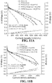
FIGS. 11A and 11B illustrate various polarizations curves;
FIG. 12A-C illustrate various VIR curves after various cycles;
FIG. 13 illustrates a nanoscale x-ray computed tomography image of a Pt/PBI-functionalized graphene catalyst according to various embodiments; and
FIG. 14 illustrates a three-dimensional TEM image of a conventional Pt/XC72 (carbon black) catalyst.
Corresponding reference characters indicate corresponding parts throughout the several views. Although the drawings represent embodiments of the present disclosure, the drawings are not necessarily to scale and certain features may be exaggerated in order to better illustrate and explain the present disclosure. The exemplification set out herein illustrates an embodiment of the disclosure, in one form, and such exemplifications are not to be construed as limiting the scope of the disclosure in any manner.
DETAILED DESCRIPTION
The embodiments disclosed below are not intended to be exhaustive or limit the disclosure to the precise forms disclosed in the following detailed description. Rather, the embodiments are chosen and described so that others skilled in the art may utilize its teachings.
As used herein, the modifier “about” used in connection with a quantity is inclusive of the stated value and has the meaning dictated by the context (for example, it includes at least the degree of error associated with the measurement of the particular quantity). When used in the context of a range, the modifier “about” should also be considered as disclosing the range defined by the absolute values of the two endpoints. For example, the range “from about 2 to about 4” also discloses the range “from 2 to 4.”
FIG. 1 illustrates method 100 according to various embodiments. Method 100 may comprise functionalizing graphene with a first functional group (step 110). The functionalizing of graphene is not particularly limited and, in various embodiments, the first functional group may comprise sulfonate, SO3H, Carboxylate, COOH, a tertiary amine, NR3 +, where R is H, alkyl, aryl, or combinations thereof, polybenzimidazole (PBI), poly(ethylene oxide) (PEO), polyphenylene oxide (PPO), polyaniline, or mixtures thereof. Method 100 may also comprise loading a metal on to the graphene. The loading of the metal is not particularly limited and may be appropriate for various metal catalysts. For example, in various embodiments, the metal may comprise Pt, Rh, Pd, Ag, Au, Ni, Os, Ir, Mn, Co, alloys thereof, oxides thereof, or mixtures thereof. For example, in various embodiments the metal may be Pt, a Pt alloy, a Pt oxide, or mixtures thereof.
Various embodiments of method 100 may include processes which yield a catalytic metallic nanoparticle having an average particle size distribution between about 1 nm to about 6 nm, for example as exemplified below. Without being limited to any theory, it is believed that methods which yield catalytic metallic nanoparticles distributed throughout the substrate may improve catalytic performance, prevent surface migration or agglomeration, and may yield more predictable life expectancy of the catalyst, for example, in a fuel cell.
FIG. 1B illustrates method 150 according to various embodiments. Method 150 may comprise functionalizing graphene with a first functional group (step 110) and loading a metal on to the graphene (step 120). Method 150 may also comprise adding a functionalized nanocarbon particle (with opposite surface energy to functional graphene made in step 110) to form a three-dimensional functionalized graphene structure (step 130).
In various embodiments, the three-dimensional functionalized graphene structure may comprise pores, channels, or a combination thereof. Without being limited to any theory, it is believed that the pores, channels, and mixtures thereof may allow for increased catalytic surface area, while providing sufficient volumetric flow for reactants supplied for catalytic reactions or products and by-products produced by the catalytic reactions. For example, in fuel cells, it is believed that the three-dimensional structures produced by method 150 may allow for improved mass transport of reactants (i.e. H2, methanol, ethanol, O2, etc.), products and water drainage, which may increase the overall fuel cell performance including improving catalytic performance, increasing fuel utilization, and reducing or preventing flooding of the electrode.
Furthermore, in various embodiments, the functionalized nanocarbon particle added in step 130 may comprise high graphitic carbons, nanographites, metal oxides, ceramics, a polymer-grafted metal oxides, and functionalized versions of these particles or combinations thereof. Without being limited to any theory, it is believed that the use of functionalized nanocarbon, metal oxide, polymer grafted metal oxides, polymer grafted Si or SiO2 or ceramic particles, may help to suppress spacer corrosion and, thus, keep the pores/channels open to help prevent electrochemical surface area loss and improve the mass transfer of reactants and products.
Also disclosed herein are products, such as functionalized graphene. According to various embodiments, the functionalized graphene may comprise graphene, a metal dispersed throughout the graphene, wherein the metal comprises one of Pt, Rh, Pd, Ag, Au, Ni, Os, Ir, Mn, Co alloys thereof, oxides thereof, or mixtures thereof, and a first functional group covalently bonded to the graphene, wherein the first functional group comprises one of sulfonate, SO3 , carboxylate, COO, a tertiary amine, NR3 +, where R is H, alkyl, aryl, or combinations thereof, polybenzimidazole (PBI), poly(ethylene oxide) (PEO), polyphenylene oxide (PPO), polyaniline, or mixtures thereof. Without being limited to any theory, it is believed that functionalized graphene having the aforementioned characteristics may have improved properties over conventional catalyst substrates.
For example, in various embodiments, the first functionalized group may help to alter the hydrophobicity of the graphene. In various embodiments, the first functionalized graphene may be added to help make the functionalized graphene hydrophilic or hydrophobic depending on the functional groups used and help decrease the contact angle. In various embodiments, the wettability of the graphene may have a contact angle between about 45° and 180°, between about 110° and about 160°, or between about 115° and about 150°.
As described above, the metal may comprise one of Pt, Rh, Pd, Ag, Au, Ni, Os, Ir, alloys thereof, oxides thereof, or mixtures thereof. Thus, in some embodiments, the metal may comprise Pt, a Pt alloy, a Pt oxide, or mixtures thereof.
Thus, in some embodiments, the functionalized graphene may be used as a catalyst support, for example in a fuel cell. Thus, in various embodiments, the functionalized graphene may be an anode or cathode. Also, in various embodiments, the anode or cathode may comprise part of a fuel cell.
Also, the first functional group may comprise one of sulfonate, SO3 , Carboxylate, COO, a tertiary amine, NR3+, where R is H, alkyl, aryl, or combinations thereof, polybenzimidazole (PBI), poly(ethylene oxide) (PEO), polyphenylene oxide (PPO), polyaniline, or mixtures thereof. For example, FIG. 6C illustrates an embodiment functionalized with SO3 , while FIG. 8 illustrates an alternative embodiment where the first functional group comprises PBI.
For example, FIG. 2 illustrates a comparison of H+ conductivity of graphene functionalized with SO3H compared to conventional graphene. As can be seen in FIG. 2, the functionalized graphene had unexpectedly improved H+ conductivity at varying relative humidity.
Similarly, FIG. 3 illustrates a comparison of e conductivity of graphene functionalized with SO3H compared to conventional graphene. As can be seen in FIG. 3, the functionalized graphene had unexpectedly lower e conductivity at varying relative humidity.
Moreover, functionalized graphene with the aforementioned properties can also exhibit better particle dispersion than conventional catalysts. For example, FIGS. 4A and 4B illustrate the particle dispersion of Pt catalysts on conventional graphene sheets. As can be seen in FIG. 4A—a transmission electron microscopy (“TEM”) image of Pt dispersed in conventional graphene—Pt particle agglomeration is present. Thus, some catalytic Pt particles are larger Pt particles. This observation can be confirmed by the histogram of FIG. 4A shown in FIG. 4B, which contains a histogram of the diameter size of the Pt particles.
However, FIGS. 5A and 5B illustrate the particle dispersion of functionalized graphene according to various embodiments. FIG. 5A is a TEM image of Pt particles in functionalized graphene. As can be seen in FIG. 5A, the Pt particle dispersion is more uniform and consistent across the functionalized graphene sheet. Thus, in various embodiments, the metal may be substantially homogeneously dispersed throughout the functionalized graphene. As used herein, the term “substantially homogeneously dispersed” may include (1) the size distribution of catalyst particles are in a tight range, namely, the smaller the difference in particle size for each particle, the more uniform distribution, (2) the distribution of inter-particle distances between different catalyst particles fall in a more narrow range.
This uniform dispersion also reduced initial Pt agglomeration when forming the functionalized graphene sheet and, thus, the Pt particle size shows a more uniform distribution, as confirmed by FIG. 5B. Thus, in various embodiments, the average particle size distribution may be between about 1 nm to about 6 nm.
Also, it is believed that the functionalized graphene disclosed herein can reduce surface migration of various metal particles, such as metal catalysts. For example, FIGS. 6A and 6B illustrate the surface migration of Pt nanoparticles on conventional graphene, while FIGS. 6C and 6D illustrate the much reduced surface migration of Pt nanoparticles on functionalized graphene sheets according to various embodiments. As can be seen in FIGS. 6A and 6B, considerable surface migration of Pt nanoparticles was evident after cycling. However, as can be seen in FIGS. 6C and 6D, graphene sheets functionalized with SO3H had considerably less surface migration of the catalytic Pt nanoparticles.
Without being limited to any theory, it is believed that the functionalized graphene may help to anchor the metal particles to the functionalized graphene and, thus, help to reduce or eliminate surface migration or agglomeration.
FIG. 7 illustrates a comparison of various substrates comprising Pt nanoparticles. The catalyst Pt nanoparticles bonded with the different carbon supports (the bonding of Pt—C) was studied using X-ray absorption spectroscopy (XAS) for the Pt L edge binding energy shift, which is illustrated in FIG. 7. The normalized X-ray absorption near edge structures (XANES) spectra for Pt L3-edge of different catalyst particles on different supports is shown in FIG. 7. The intensity of Pt L3-edge of the different catalyst particles on different supports was plotted vs the bind energy (eV). The stronger the Pt—C interaction is, the higher the intensity of the L-edge is, which gives the order of Pt—C weak bonding strength: Pt/SO3H-G>Pt/SO3H-XC72 carbon black>Pt/G>Pt/XC72 carbon black. Clearly, functionalized graphene enhanced the Pt anchoring (illustrated also by TEM in FIGS. 6C and 6D and in FIG. 7) and, consequently, it also enhances Pt nanoparticle stability, as evidenced by MEA cycling results illustrated in the table below. The Y axis in FIG. 7 is the Pt.
TABLE 1
Summary of Pt Intensity
Intensity of
Sample Pt L3-edge
Unsupported Pt 1.15341
Pt/SO3H-graphene 1.35368
Pt/SO3H-XC-72 carbon black 1.29534
Pt/graphene 1.27472
Pt/SC-72 carbon black 1.23330
Also, it is believed that the functionalized graphene of the present disclosure can form various three-dimensional structures, such as shown in FIG. 8. FIG. 8 illustrates an assembly of functionalized graphene 810 and functionalized nanocarbons (FNC) 820 according to various embodiments. Functionalized graphene 810 may comprise a functional group that may be charged, such as exemplified positively charged group 815. In the exemplified embodiment illustrated in FIG. 8, the graphene is functionalized with polybenzimidazole (PBI). While PBI is exemplified, any suitable functional group could be used, such sulfonate, SO3H, carboxylate, COOH, a tertiary amine, NR3 +, where R is H, alkyl, aryl, or combinations thereof, polybenzimidazole (PBI), poly(ethylene oxide) (PEO), polyphenylene oxide (PPO), polyaniline, or mixtures thereof.
Functionalized nanocarbon 820 similarly may comprise a charged functionalized group, such as exemplary negatively charged group 825. The functional group of FNC 820 is not particularly limited and may comprise a metal oxide, a polymer coated metal oxide, or polymer grafted Si or SiO2, or ceramic particles, or combinations thereof.
In various embodiments the addition of FNC 820 to the functionalized graphene 810 may cause FNC 820 and functionalized graphene 810 to self-assemble into three-dimensional structure 800. Thus, in various embodiments, the functionalized graphene may form a three-dimensional structure. Also, in various embodiments the three-dimensional structure may comprise a functionalized nanocarbon particle. FIG. 9 contains a TEM image of a three-dimensional structure comprising FNC and functionalized graphene according to various embodiments.
With reference back to FIG. 8, the three-dimensional structure may comprise a second functionalized graphene 811, wherein the functionalized nanocarbon particle 820 is located between the functionalized graphene sheets and the second functionalized graphene. The placement of the FNC may cause the formation of pores or channels. In various embodiments, the pores or channels may have an average pore size between about 3 nm to about 2,000 nm, between about 25 nm and 1,000 nm, or between about 50 nm and about 750 nm. For example, FIG. 10 contains a comparison of the measurement of pore size as a derivative of pore volume with the pore size. As can be seen in FIG. 10, functionalized graphene with the addition of a functionalized nanocarbon particle had much large pore volume distribution than carbon black (XC72, commercially available from the Cabot Corporation) or functionalized graphene itself. Without being limited to any theory, it is believed that—in some embodiments—reducing the dimension of the graphene sheets can effectively or substantially improve the performance of graphene supported catalysts, for example, in fuel cells.
FIG. 13 illustrates a nanoscale tomography image of a Pt/PBI-functionalized graphene catalyst layer in a membrane electrode assembly (MEA) measured by x-raynano-CT technique, according to various embodiments. As can be seen in FIG. 13, the functionalized graphene catalyst layer has a quite large pore volume and very uniform distribution of the pore structure, and these pores are connected to each other (they are open pores) which are represented by the clouds. These pore structures confirms that the claimed 3-D structure in FIG. 8 has been achieved which consequently lead to the superior fuel cell performance in FIGS. 11 and 12.
FIGS. 11A and 11B illustrate a comparison of membrane electrode assemblies (MEAs) comprising conventional materials (carbon black and graphene) and various membrane electrode assemblies comprising functionalized graphene according to various embodiments. As can be seen in FIGS. 11A and 11B, the functionalized graphene with FNC prepared following method 130 had unexpected improvements over conventional graphene at various current densities.
FIG. 12A-B illustrate various VIR curves after various accelerated stress test (AST) cycles. FIGS. 12A and 12B illustrates various VIR curves for different intervals for graphene functionalized with PBI and comprising a Pt metal according to various embodiments. FIG. 12B illustrates conventional carbon black (XC72) comprising Pt metal particles. As can be seen in FIGS. 12A and 12B, the functionalized graphene with FNC has much better stability AST cycling performance than the conventional carbon black illustrated in FIG. 12B. The functionalized graphene had a much less performance loss from mass activity, and had a higher performance after cycling. Also, the functionalized graphene with FNC showed improved Electrochemical Surface Area (ECSA) loss than conventional catalysts using carbon black and graphene. FIG. 12C illustrates the various VIR curves of functionalized graphene supported Pt particles at different accelerated stress test (AST) for Pt catalyst particles by potential cycling from 0.6V-1.0V for total 30K cycles. As can be seen in FIGS. 12A and 12C, catalysts with functionalized graphene may be much more stable than conventional catalysts having carbon black.
While this disclosure has been described as having an exemplary design, the present disclosure may be further modified within the spirit and scope of this disclosure. This application is therefore intended to cover any variations, uses, or adaptations of the disclosure using its general principles. Further, this application is intended to cover such departures from the present disclosure as come within known or customary practice in the art to which this disclosure pertains.
Benefits, other advantages, and solutions to problems have been described herein with regard to specific embodiments. Furthermore, the connecting lines shown in the various figures contained herein are intended to represent exemplary functional relationships and/or physical couplings between the various elements. It should be noted that many alternative or additional functional relationships or physical connections may be present in a practical system. However, the benefits, advantages, solutions to problems, and any elements that may cause any benefit, advantage, or solution to occur or become more pronounced are not to be construed as critical, required, or essential features or elements. The scope is accordingly to be limited by nothing other than the appended claims, in which reference to an element in the singular is not intended to mean “one and only one” unless explicitly so stated, but rather “one or more.” Moreover, where a phrase similar to “at least one of A, B, or C” is used in the claims, it is intended that the phrase be interpreted to mean that A alone may be present in an embodiment, B alone may be present in an embodiment, C alone may be present in an embodiment, or that any combination of the elements A, B, or C may be present in a single embodiment; for example, A and B, A and C, B and C, or A and B and C. Different cross-hatching is used throughout the figures to denote different parts but not necessarily to denote the same or different materials.
Systems, methods and apparatuses are provided herein. In the detailed description herein, references to “one embodiment,” “an embodiment,” “an example embodiment,” etc., indicate that the embodiment described may include a particular feature, structure, or characteristic, but every embodiment may not necessarily include the particular feature, structure, or characteristic. Moreover, such phrases are not necessarily referring to the same embodiment. Further, when a particular feature, structure, or characteristic is described in connection with an embodiment, it is submitted that it is within the knowledge of one skilled in the art to affect such feature, structure, or characteristic in connection with other embodiments whether or not explicitly described. After reading the description, it will be apparent to one skilled in the relevant art(s) how to implement the disclosure in alternative embodiments.
Furthermore, no element, component, or method step in the present disclosure is intended to be dedicated to the public regardless of whether the element, component, or method step is explicitly recited in the claims. No claim element herein is to be construed under the provisions of 35 U.S.C. § 112(f), unless the element is expressly recited using the phrase “means for.” As used herein, the terms “comprises,” “comprising,” or any other variation thereof, are intended to cover a non-exclusive inclusion, such that a process, method, article, or apparatus that comprises a list of elements does not include only those elements but may include other elements not expressly listed or inherent to such process, method, article, or apparatus.

Claims (4)

What is claimed is:
1. A three-dimensional functionalized graphene structure comprising:
a first functionalized graphene comprising:
a first graphene sheet;
a metal dispersed throughout the first graphene sheet, wherein the metal comprises at least one of Pt, Rh, Pd, Ag, Au, Ni, Os, Ir, Mn, Co, alloys thereof, oxides thereof, or mixtures thereof;
a first functional group covalently bonded to the first graphene sheet, wherein the first functional group comprises at least one of sulfonate, SO3—, Carboxylate, COO—, a tertiary amine, NR3+, where R is H, alkyl, aryl, or combinations thereof, polybenzimidazole (PBI), poly(ethylene oxide) (PEO), polyphenylene oxide (PPO), polyaniline, or mixtures thereof;
a second functionalized graphene; and
a functionalized nanocarbon particle located between the first and second functionalized graphenes, wherein the functionalized nanocarbon particle has an opposite surface charge compared to the first functional group of the first functionalized graphene.
2. The three-dimensional functionalized graphene structure of claim 1, wherein:
the first functionalized graphene has a positively charged first functional group; and
the functionalized nanocarbon has a negatively charged functional group.
3. The three-dimensional functionalized graphene structure of claim 1, wherein the functionalized nanocarbon particle forms at least one of pores, channels, or a combination thereof between the first and second functionalized graphenes that allow mass transport of reactants and products between the first and second functionalized graphenes.
4. The three-dimensional functionalized graphene structure of claim 3, wherein the structure has an average pore size between about 3 nm to about 2,000 nm.
US15/377,976 2015-12-14 2016-12-13 Systems and methods of graphene supported catalysts Active 2038-05-18 US10886540B2 (en)

Priority Applications (1)

Application Number Priority Date Filing Date Title
US15/377,976 US10886540B2 (en) 2015-12-14 2016-12-13 Systems and methods of graphene supported catalysts

Applications Claiming Priority (2)

Application Number Priority Date Filing Date Title
US201562267156P 2015-12-14 2015-12-14
US15/377,976 US10886540B2 (en) 2015-12-14 2016-12-13 Systems and methods of graphene supported catalysts

Publications (2)

Publication Number Publication Date
US20170170487A1 US20170170487A1 (en) 2017-06-15
US10886540B2 true US10886540B2 (en) 2021-01-05

Family

ID=59018509

Family Applications (1)

Application Number Title Priority Date Filing Date
US15/377,976 Active 2038-05-18 US10886540B2 (en) 2015-12-14 2016-12-13 Systems and methods of graphene supported catalysts

Country Status (1)

Country Link
US (1) US10886540B2 (en)

Cited By (3)

* Cited by examiner, † Cited by third party
Publication number Priority date Publication date Assignee Title
US11145875B2 (en) * 2019-08-19 2021-10-12 Robert Bosch Gmbh Fuel cell electrode catalyst layer coating
US11631863B2 (en) 2020-03-27 2023-04-18 Robert Bosch Gmbh Fuel cell catalyst material with defective, carbon-based coating
US11670790B2 (en) 2019-11-25 2023-06-06 Robert Bosch Gmbh Fuel cell membrane electrode assemblies

Families Citing this family (6)

* Cited by examiner, † Cited by third party
Publication number Priority date Publication date Assignee Title
CN108417810B (en) * 2018-03-23 2021-02-26 合肥国轩高科动力能源有限公司 Preparation method of polyaniline/graphene/silicon composite material with three-dimensional network structure
CN110872465B (en) * 2018-08-29 2022-02-01 中国石油化工股份有限公司 Graphene insulating coating and preparation method and application thereof
CN112886025A (en) * 2019-11-29 2021-06-01 大连大学 Fructose fuel cell and construction method thereof
CN112242528B (en) * 2020-09-24 2021-09-28 江苏理工学院 Preparation method and application of functionalized graphene ORR catalyst
CN112531178A (en) * 2020-11-23 2021-03-19 上海纳米技术及应用国家工程研究中心有限公司 Fuel cell cathode multi-metal doped multi-element non-metal oxygen reduction catalyst and preparation method thereof
KR20220078747A (en) * 2020-12-03 2022-06-13 현대자동차주식회사 Catalyst Complex For Fuel Cell And Method For Manufacturing The Same

Citations (9)

* Cited by examiner, † Cited by third party
Publication number Priority date Publication date Assignee Title
US20100222206A1 (en) * 2007-10-05 2010-09-02 Shin-Etsu Chemical Co., Ltd. Method for production of electrode catalyst for fuel cell
US20110017587A1 (en) * 2009-07-27 2011-01-27 Aruna Zhamu Production of chemically functionalized nano graphene materials
US20120208088A1 (en) * 2011-02-13 2012-08-16 Jian Xie High surface area nano-structured graphene composites and capacitive devices incorporating the same
US20120245018A1 (en) * 2011-03-24 2012-09-27 Council Of Scientific & Industrial Research High aspect ratio nanoscale multifunctional materials
US20130236816A1 (en) * 2010-11-16 2013-09-12 Korea Institute Of Energy Research Method for producing porous carbon materials having mesopores and catalyst support for a fuel cell produced using same
US20150255801A1 (en) * 2012-07-07 2015-09-10 Indian Institute Of Technology Madras Metal nanoparticle-graphene composites and methods for their preparation and use
US20160293972A1 (en) * 2013-11-20 2016-10-06 William Marsh Rice University Carbon-based catalysts for oxygen reduction reactions
US20170279143A1 (en) * 2014-10-24 2017-09-28 Mitsui Mining & Smelting Co., Ltd. Fuel cell electrode catalyst layer, production method therefor, membrane electrode assembly, and solid polymer fuel cell
US20180006313A1 (en) * 2014-12-22 2018-01-04 Basf Se Carbon supported catalyst comprising a modifier and process for preparing the carbon supported catalyst

Patent Citations (9)

* Cited by examiner, † Cited by third party
Publication number Priority date Publication date Assignee Title
US20100222206A1 (en) * 2007-10-05 2010-09-02 Shin-Etsu Chemical Co., Ltd. Method for production of electrode catalyst for fuel cell
US20110017587A1 (en) * 2009-07-27 2011-01-27 Aruna Zhamu Production of chemically functionalized nano graphene materials
US20130236816A1 (en) * 2010-11-16 2013-09-12 Korea Institute Of Energy Research Method for producing porous carbon materials having mesopores and catalyst support for a fuel cell produced using same
US20120208088A1 (en) * 2011-02-13 2012-08-16 Jian Xie High surface area nano-structured graphene composites and capacitive devices incorporating the same
US20120245018A1 (en) * 2011-03-24 2012-09-27 Council Of Scientific & Industrial Research High aspect ratio nanoscale multifunctional materials
US20150255801A1 (en) * 2012-07-07 2015-09-10 Indian Institute Of Technology Madras Metal nanoparticle-graphene composites and methods for their preparation and use
US20160293972A1 (en) * 2013-11-20 2016-10-06 William Marsh Rice University Carbon-based catalysts for oxygen reduction reactions
US20170279143A1 (en) * 2014-10-24 2017-09-28 Mitsui Mining & Smelting Co., Ltd. Fuel cell electrode catalyst layer, production method therefor, membrane electrode assembly, and solid polymer fuel cell
US20180006313A1 (en) * 2014-12-22 2018-01-04 Basf Se Carbon supported catalyst comprising a modifier and process for preparing the carbon supported catalyst

Non-Patent Citations (1)

* Cited by examiner, † Cited by third party
Title
Tsuyohiko Fujigaya and Naotoshi Nakashima; "Fuel Cell Electrocatalyst Using Polybenzimidazole-Modified Carbon Nanotubes as Support Materials", 2013, Advanced Materials, 25, 1666-1681 (Year: 2013). *

Cited By (3)

* Cited by examiner, † Cited by third party
Publication number Priority date Publication date Assignee Title
US11145875B2 (en) * 2019-08-19 2021-10-12 Robert Bosch Gmbh Fuel cell electrode catalyst layer coating
US11670790B2 (en) 2019-11-25 2023-06-06 Robert Bosch Gmbh Fuel cell membrane electrode assemblies
US11631863B2 (en) 2020-03-27 2023-04-18 Robert Bosch Gmbh Fuel cell catalyst material with defective, carbon-based coating

Also Published As

Publication number Publication date
US20170170487A1 (en) 2017-06-15

Similar Documents

Publication Publication Date Title
US10886540B2 (en) Systems and methods of graphene supported catalysts
Antolini Composite materials: an emerging class of fuel cell catalyst supports
JP5924530B2 (en) Gas diffusion layer for fuel cells
US10985382B2 (en) Core-shell structure type nanosheet
JP5002939B2 (en) Fuel cell electrolyte membrane and membrane electrode assembly
CN107851803B (en) Electrocatalytically active nanocomposite material and method for the production thereof
CN107959030B (en) Nanostructured PEMFC electrodes
JP5458503B2 (en) Method for producing electrolyte membrane-electrode assembly
TWI728612B (en) Catalyst, method for manufacturing the same, electrode comprising the same, membrane-electrode assembly comprising the same, and fuel cell comprising the same
Cui et al. Self-assembled phosphomolybdic acid–polyaniline–graphene composite-supported efficient catalyst towards methanol oxidation
Xin et al. Polybenzimidazole (PBI) functionalized nanographene as highly stable catalyst support for polymer electrolyte membrane fuel cells (PEMFCs)
US20230203696A1 (en) Method for making ultralow platinum loading and high durability membrane electrode assembly for polymer electrolyte membrane fuel cells
JP7349500B2 (en) Fuel cell catalyst
Aoun et al. Effect of the OH−/Pt ratio during polyol synthesis on metal loading and particle size in DMFC catalysts
US11394032B2 (en) Ionomer/catalyst interface
US20130264524A1 (en) Electrode and fabrication method thereof
JP2009140657A (en) Electrode catalyst for fuel cell
JP2007323824A (en) Manufacturing method of electrode for fuel cell and electrode for fuel cell
JP6297939B2 (en) Cathode electrode structure and membrane / electrode assembly
KR101982744B1 (en) Catalyst for fuel cell and method of manufacturing the same, and membrane-electrode assmbly and method of manufacturing the same
JP2006294267A (en) Catalyst ink for fuel cell electrode formation
JP2016110888A (en) Method of manufacturing electrode catalyst layer for fuel cell
US11699795B2 (en) Method for producing carrier for electrode catalyst, precursor of carrier for electrode catalyst, and carrier for electrode catalyst, comprising same
WO2018094266A1 (en) Membrane electrode assembly with improved electrode
JP2012243656A (en) Method for producing membrane electrode assembly, and membrane electrode assembly

Legal Events

Date Code Title Description
AS Assignment

Owner name: INDIANA UNIVERSITY RESEARCH AND TECHNOLOGY CORPORA

Free format text: ASSIGNMENT OF ASSIGNORS INTEREST;ASSIGNORS:XIE, JIAN;LI, ZHE-FEI;XIN, LE;SIGNING DATES FROM 20160226 TO 20160316;REEL/FRAME:040662/0650

Owner name: INDIANA UNIVERSITY RESEARCH AND TECHNOLOGY CORPORATION, INDIANA

Free format text: ASSIGNMENT OF ASSIGNORS INTEREST;ASSIGNORS:XIE, JIAN;LI, ZHE-FEI;XIN, LE;SIGNING DATES FROM 20160226 TO 20160316;REEL/FRAME:040662/0650

STPP Information on status: patent application and granting procedure in general

Free format text: RESPONSE AFTER FINAL ACTION FORWARDED TO EXAMINER

STPP Information on status: patent application and granting procedure in general

Free format text: NON FINAL ACTION MAILED

STPP Information on status: patent application and granting procedure in general

Free format text: RESPONSE TO NON-FINAL OFFICE ACTION ENTERED AND FORWARDED TO EXAMINER

STPP Information on status: patent application and granting procedure in general

Free format text: NON FINAL ACTION MAILED

STPP Information on status: patent application and granting procedure in general

Free format text: RESPONSE TO NON-FINAL OFFICE ACTION ENTERED AND FORWARDED TO EXAMINER

STPP Information on status: patent application and granting procedure in general

Free format text: FINAL REJECTION MAILED

STPP Information on status: patent application and granting procedure in general

Free format text: NOTICE OF ALLOWANCE MAILED -- APPLICATION RECEIVED IN OFFICE OF PUBLICATIONS

STCF Information on status: patent grant

Free format text: PATENTED CASE