US10530177B2 - Multi-loop implant charger - Google Patents
Multi-loop implant charger Download PDFInfo
- Publication number
- US10530177B2 US10530177B2 US15/454,105 US201715454105A US10530177B2 US 10530177 B2 US10530177 B2 US 10530177B2 US 201715454105 A US201715454105 A US 201715454105A US 10530177 B2 US10530177 B2 US 10530177B2
- Authority
- US
- United States
- Prior art keywords
- coil
- magnetic field
- implantable
- amplitude
- phase
- Prior art date
- Legal status (The legal status is an assumption and is not a legal conclusion. Google has not performed a legal analysis and makes no representation as to the accuracy of the status listed.)
- Active, expires
Links
- 239000007943 implant Substances 0.000 title abstract description 37
- 230000005291 magnetic effect Effects 0.000 claims abstract description 158
- 238000000034 method Methods 0.000 claims abstract description 45
- 239000013598 vector Substances 0.000 claims description 24
- 230000005284 excitation Effects 0.000 claims description 12
- 230000004044 response Effects 0.000 claims description 5
- 238000012546 transfer Methods 0.000 claims description 4
- 238000010586 diagram Methods 0.000 description 14
- 230000004907 flux Effects 0.000 description 14
- 230000008859 change Effects 0.000 description 6
- 238000004891 communication Methods 0.000 description 6
- 210000003477 cochlea Anatomy 0.000 description 4
- 230000004936 stimulating effect Effects 0.000 description 4
- 230000000638 stimulation Effects 0.000 description 4
- 239000003990 capacitor Substances 0.000 description 3
- 230000001939 inductive effect Effects 0.000 description 3
- 230000005236 sound signal Effects 0.000 description 3
- 230000008878 coupling Effects 0.000 description 2
- 238000010168 coupling process Methods 0.000 description 2
- 238000005859 coupling reaction Methods 0.000 description 2
- 230000007423 decrease Effects 0.000 description 2
- 230000000694 effects Effects 0.000 description 2
- 230000006870 function Effects 0.000 description 2
- 230000001965 increasing effect Effects 0.000 description 2
- 238000007726 management method Methods 0.000 description 2
- 238000012986 modification Methods 0.000 description 2
- 230000004048 modification Effects 0.000 description 2
- 238000000465 moulding Methods 0.000 description 2
- BASFCYQUMIYNBI-UHFFFAOYSA-N platinum Substances [Pt] BASFCYQUMIYNBI-UHFFFAOYSA-N 0.000 description 2
- 230000009467 reduction Effects 0.000 description 2
- 238000004804 winding Methods 0.000 description 2
- 208000027418 Wounds and injury Diseases 0.000 description 1
- 210000003484 anatomy Anatomy 0.000 description 1
- 230000008901 benefit Effects 0.000 description 1
- 230000002902 bimodal effect Effects 0.000 description 1
- 210000000988 bone and bone Anatomy 0.000 description 1
- 210000000133 brain stem Anatomy 0.000 description 1
- 210000004027 cell Anatomy 0.000 description 1
- 210000000860 cochlear nerve Anatomy 0.000 description 1
- 239000004020 conductor Substances 0.000 description 1
- 230000006378 damage Effects 0.000 description 1
- 230000003247 decreasing effect Effects 0.000 description 1
- 230000002950 deficient Effects 0.000 description 1
- 230000001419 dependent effect Effects 0.000 description 1
- 238000003745 diagnosis Methods 0.000 description 1
- 201000010099 disease Diseases 0.000 description 1
- 208000037265 diseases, disorders, signs and symptoms Diseases 0.000 description 1
- 238000010292 electrical insulation Methods 0.000 description 1
- PCHJSUWPFVWCPO-UHFFFAOYSA-N gold Chemical compound [Au] PCHJSUWPFVWCPO-UHFFFAOYSA-N 0.000 description 1
- 210000002768 hair cell Anatomy 0.000 description 1
- 210000003128 head Anatomy 0.000 description 1
- 208000014674 injury Diseases 0.000 description 1
- 238000002955 isolation Methods 0.000 description 1
- 239000000696 magnetic material Substances 0.000 description 1
- 238000012544 monitoring process Methods 0.000 description 1
- 230000001537 neural effect Effects 0.000 description 1
- 238000005457 optimization Methods 0.000 description 1
- 230000035790 physiological processes and functions Effects 0.000 description 1
- 229910052697 platinum Inorganic materials 0.000 description 1
- 229920001296 polysiloxane Polymers 0.000 description 1
- 230000002265 prevention Effects 0.000 description 1
- 230000008569 process Effects 0.000 description 1
- 238000012545 processing Methods 0.000 description 1
- 230000000717 retained effect Effects 0.000 description 1
- 230000000630 rising effect Effects 0.000 description 1
- 238000010408 sweeping Methods 0.000 description 1
- 208000024891 symptom Diseases 0.000 description 1
- 230000001225 therapeutic effect Effects 0.000 description 1
- 210000001519 tissue Anatomy 0.000 description 1
- 238000011282 treatment Methods 0.000 description 1
Images


Classifications
-
- H02J7/025—
-
- A—HUMAN NECESSITIES
- A61—MEDICAL OR VETERINARY SCIENCE; HYGIENE
- A61N—ELECTROTHERAPY; MAGNETOTHERAPY; RADIATION THERAPY; ULTRASOUND THERAPY
- A61N1/00—Electrotherapy; Circuits therefor
- A61N1/18—Applying electric currents by contact electrodes
- A61N1/32—Applying electric currents by contact electrodes alternating or intermittent currents
- A61N1/36—Applying electric currents by contact electrodes alternating or intermittent currents for stimulation
- A61N1/372—Arrangements in connection with the implantation of stimulators
- A61N1/378—Electrical supply
- A61N1/3787—Electrical supply from an external energy source
-
- H—ELECTRICITY
- H02—GENERATION; CONVERSION OR DISTRIBUTION OF ELECTRIC POWER
- H02J—CIRCUIT ARRANGEMENTS OR SYSTEMS FOR SUPPLYING OR DISTRIBUTING ELECTRIC POWER; SYSTEMS FOR STORING ELECTRIC ENERGY
- H02J50/00—Circuit arrangements or systems for wireless supply or distribution of electric power
- H02J50/10—Circuit arrangements or systems for wireless supply or distribution of electric power using inductive coupling
- H02J50/12—Circuit arrangements or systems for wireless supply or distribution of electric power using inductive coupling of the resonant type
-
- H—ELECTRICITY
- H02—GENERATION; CONVERSION OR DISTRIBUTION OF ELECTRIC POWER
- H02J—CIRCUIT ARRANGEMENTS OR SYSTEMS FOR SUPPLYING OR DISTRIBUTING ELECTRIC POWER; SYSTEMS FOR STORING ELECTRIC ENERGY
- H02J50/00—Circuit arrangements or systems for wireless supply or distribution of electric power
- H02J50/40—Circuit arrangements or systems for wireless supply or distribution of electric power using two or more transmitting or receiving devices
- H02J50/402—Circuit arrangements or systems for wireless supply or distribution of electric power using two or more transmitting or receiving devices the two or more transmitting or the two or more receiving devices being integrated in the same unit, e.g. power mats with several coils or antennas with several sub-antennas
-
- H—ELECTRICITY
- H02—GENERATION; CONVERSION OR DISTRIBUTION OF ELECTRIC POWER
- H02J—CIRCUIT ARRANGEMENTS OR SYSTEMS FOR SUPPLYING OR DISTRIBUTING ELECTRIC POWER; SYSTEMS FOR STORING ELECTRIC ENERGY
- H02J7/00—Circuit arrangements for charging or depolarising batteries or for supplying loads from batteries
- H02J7/00032—Circuit arrangements for charging or depolarising batteries or for supplying loads from batteries characterised by data exchange
- H02J7/00034—Charger exchanging data with an electronic device, i.e. telephone, whose internal battery is under charge
-
- A—HUMAN NECESSITIES
- A61—MEDICAL OR VETERINARY SCIENCE; HYGIENE
- A61N—ELECTROTHERAPY; MAGNETOTHERAPY; RADIATION THERAPY; ULTRASOUND THERAPY
- A61N1/00—Electrotherapy; Circuits therefor
- A61N1/18—Applying electric currents by contact electrodes
- A61N1/32—Applying electric currents by contact electrodes alternating or intermittent currents
- A61N1/36—Applying electric currents by contact electrodes alternating or intermittent currents for stimulation
- A61N1/36036—Applying electric currents by contact electrodes alternating or intermittent currents for stimulation of the outer, middle or inner ear
- A61N1/36038—Cochlear stimulation
-
- H—ELECTRICITY
- H02—GENERATION; CONVERSION OR DISTRIBUTION OF ELECTRIC POWER
- H02J—CIRCUIT ARRANGEMENTS OR SYSTEMS FOR SUPPLYING OR DISTRIBUTING ELECTRIC POWER; SYSTEMS FOR STORING ELECTRIC ENERGY
- H02J2310/00—The network for supplying or distributing electric power characterised by its spatial reach or by the load
- H02J2310/10—The network having a local or delimited stationary reach
- H02J2310/20—The network being internal to a load
- H02J2310/23—The load being a medical device, a medical implant, or a life supporting device
Definitions
- the present invention relates generally to charging of implantable medical devices.
- Implantable medical devices Medical devices having one or more implantable components, generally referred to herein as implantable medical devices, have provided a wide range of therapeutic benefits to recipients over recent decades.
- partially or fully-implantable medical devices such as hearing prostheses (e.g., bone conduction devices, mechanical stimulators, cochlear implants, etc.), implantable pacemakers, defibrillators, functional electrical stimulation devices, and other implantable medical devices, have been successful in performing lifesaving and/or lifestyle enhancement functions for a number of years.
- implantable medical devices have increased over the years.
- many implantable medical devices now often include one or more instruments, apparatus, sensors, processors, controllers or other functional mechanical or electrical components that are permanently or temporarily implanted in a recipient.
- These functional components perform diagnosis, prevention, monitoring, treatment or management of a disease or injury or symptom thereof, or are employed to investigate, replace or modify the anatomy or a physiological process.
- Many of these functional components utilize power and/or data received from external components that are part of, or operate in conjunction with, the implantable medical device.
- a method for wireless transfer of power from a wireless charger to an implantable component having an implantable coil comprises: delivering a first alternating current signal to a first coil antenna of the wireless charger so as to produce a first magnetic field; delivering a second alternating current signal to a second coil antenna of the wireless charger so as to produce a second magnetic field, wherein the second alternating current signal causes at least one of the phase or amplitude of the second magnetic field to vary with respect to the phase or amplitude of the first magnetic field; and receiving, at the implantable coil, a combined magnetic field comprised of the first and second magnetic fields, wherein the combined magnetic field generates an alternating current signal at the implantable coil.
- an external charger device for an implantable medical device.
- the external charger device comprises: at least first and second coil antennas configured to generate first and second magnetic fields, respectively; and a coil excitation system connected to the first and second coil antennas and configured to independently drive the first and second coil antennas so that at least one characteristic of the first magnetic field varies, over time, with respect to the same at least one characteristic of the second magnetic field.
- an implantable medical device system comprises: an external charger including: at least first and second external coil antennas in close proximity to one another and configured to emit first and second magnetic fields that collectively generate a combined magnetic field having a combined magnetic field vector; and a coil excitation system connected to the first and second coil antennas and configured to drive the first and second coil antennas with time variant waveforms to cause fluctuation in an orientation of the combined magnetic field vector.
- FIG. 1 is a block diagram illustrating a cochlear implant system, in accordance with embodiments presented herein;
- FIG. 2A is block diagram of a cochlear implant, in accordance with embodiments presented herein;
- FIG. 2B is a block diagram of an external charging device, in accordance with embodiments presented herein;
- FIG. 2C is a schematic block diagram illustrating further details of the external charging device of FIG. 2B ;
- FIGS. 3A and 3B are schematic diagrams illustrating coil antennas of the external charging device of FIG. 2B ;
- FIG. 4 is a block diagram of another external charging device, in accordance with embodiments presented herein;
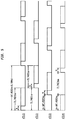
- FIG. 5 is a diagram illustrating the generation of phase variations between two magnetic fields, in accordance with embodiments presented herein;
- FIGS. 6A and 6B are diagrams illustrating voltages detected at an implantable coil, in accordance with embodiments presented herein;
- FIG. 7 is a flowchart of a method, in accordance with embodiments presented herein.
- FIG. 8A is a flowchart of a method, in accordance with certain embodiments presented herein.
- FIG. 8B is a flowchart of a method, in accordance with certain embodiments presented herein.
- FIG. 8C is a flowchart of a method, in accordance with certain embodiments presented herein.
- FIG. 8D is a flowchart of a method, in accordance with certain embodiments presented herein.
- FIG. 8E is a flowchart of a method, in accordance with certain embodiments presented herein.
- a multi-loop (multi-antenna) external charging device sometimes referred to herein as an external or wireless charger, includes a plurality of external coil/loop antennas that are each configured to emit a magnetic field that is received by an implantable coil of the implantable component. At least one characteristic (e.g., phases, amplitudes, etc.) of the emitted magnetic fields are varied relative to one another over time.
- the direction/orientation of the combined magnetic field vector also changes (e.g., rotates) over time and, accordingly, the location of the dead charging zones will also change over time.
- the implantable coil will, at different times, have a non-zero amount of magnetic flux there through that induces a current in the implantable coil.
- the external charger can be an “open-loop” charger manufactured without a communications interface/circuitry to detect load modulation from the implant or can be a device that is configured to default to an “open-loop” configuration (i.e., to operate without feedback from the implant) in the absence of a communication signal from the implant (e.g. for backward compatibility, when interference prevents reliable data communication, etc.).
- implantable medical device systems there are a number of different types of implantable medical device systems in which embodiments of the present invention may be implemented. However, merely for ease of illustration, the techniques presented herein are primarily described with reference to one type of implantable medical device system, namely a cochlear implant system. It is to be appreciated that the techniques presented herein may be used in any other partially or fully implantable medical device system now known or later developed, including other auditory prosthesis systems, such as systems that include auditory brainstem stimulators, electro-acoustic hearing prostheses, bimodal hearing prostheses, etc.
- FIG. 1 is a block diagram of an exemplary cochlear implants system 101 in which embodiments presented herein are implemented.
- the cochlear implant system 101 comprises an implantable component, referred to as cochlear implant 100 , and an external charging device, sometimes referred to herein as a wireless or external charger 103 .
- the external charger 103 may have a number of different forms, such as a pillow charger, charging mat, etc.
- the cochlear implant 100 comprises a rechargeable battery (not shown in FIG. 1 ) that is configured to be recharged using power signals received from the external charger 103 via an inductive radio frequency (RF) link.
- the external charger 103 is a multi-loop (multi-antenna) device that includes two or more coil antennas (antenna loops) that each emit a magnetic field. The two or more coil antennas are driven such that the phases and/or amplitudes of the emitted magnetic fields vary (continuously or discontinuously), over time, relative to one another. As a result, the orientation of a summed magnetic field vector (corresponding to the summation of the emitted magnetic fields) changes (e.g., rotates) over time.
- FIG. 2A is a block diagram illustrating one example arrangement for the cochlear implant 100 , referred to as cochlear implant 200 .
- the cochlear implant 200 is a totally implantable cochlear implant where all components of the cochlear implant are configured to be implanted under the skin/tissue 205 of a recipient. Because all components are implantable, cochlear implant 200 operates, for at least a finite period of time, without the presence of an external device (e.g., without external charger 203 ).
- Cochlear implant 200 includes an implant body (main module) 210 , a lead region 214 , and an elongate intra-cochlear stimulating assembly 216 .
- the implant body 210 generally comprises a hermetically-sealed housing 218 in which a stimulator unit (stimulation electronics) 222 , a sound processor 224 , an implant controller 226 (i.e., battery and power management component or battery processor), RF interface circuitry 228 , and a rechargeable battery 230 are disposed.
- cochlear implant 200 may include one or more other components that, for ease of illustration, have been omitted from FIG. 2A .
- the implant body 210 also includes one or more implantable microphones 212 and an internal/implantable coil 232 that are each typically located external to the housing 218 .
- the implantable coil 232 are connected to elements within the housing 218 via hermetic feedthroughs (not shown in FIG. 2 ).
- Implantable coil 232 is typically a wire antenna coil comprised of multiple turns of electrically insulated single-strand or multi-strand platinum or gold wire.
- the electrical insulation of implantable coil 232 is provided by a flexible molding (e.g., silicone molding), which is not shown in FIG. 2A .
- a magnet is fixed relative to the implantable coil 232 for magnetic coupling with a magnet in an external device.
- Elongate stimulating assembly 216 is configured to be at least partially implanted in the recipient's cochlea (not shown) and includes a plurality of longitudinally spaced intra-cochlear electrical stimulating contacts (electrodes) 234 that collectively form a contact array 236 for delivery of electrical stimulation (current) to the recipient's cochlea.
- Stimulating assembly 216 extends through an opening in the cochlea (e.g., cochleostomy, the round window, etc.) and has a proximal end connected to the stimulator unit 222 via the lead region 214 and a hermetic feedthrough (not shown in FIG. 2 ).
- Lead region 214 includes one or more conductors (wires) that electrically couple the electrodes 234 to the stimulator unit 222 .
- cochlear implant 200 electrically stimulates the recipient's auditory nerve cells, bypassing absent or defective hair cells that normally transduce acoustic vibrations into neural activity, in a manner that causes the recipient to perceive one or more components of the received sound signals.
- the one or more implantable microphones 212 are configured to detect/receive input sound signals that are provided to the sound processor 224 by the RF interface circuitry 228 .
- the sound processor 212 is configured to execute sound processing and coding to convert the received sound signals into output signals for use by the stimulator unit 222 in delivering electrical stimulation (current) to the recipient via electrodes 234 .
- the implantable coil 232 enables cochlear implant 200 to receive power/current signals from an external charger (e.g., external charger 103 ) via an RF link, sometimes referred to herein as an inductive power link, which is represented in FIG. 2A by arrow 242 .
- the rechargeable battery 230 is configured to store the energy needed to power the other elements of the cochlear implant 200 , as well as to provide the current needed to electrically stimulate the recipient's cochlea.
- the RF interface circuitry 228 is configured to operate under the control of the implant controller 226 and contains the necessary switches so as to charge the rechargeable battery 230 using the power received via inductive power link 242 .
- conventional external chargers typically include a single transmit coil that is used to generate a magnetic field that is received at an implantable coil.
- a current is induced in the implantable coil that, in turn, can be used to charge a battery.
- the amount of current induced in the implantable coil is related to the total magnetic flux enclosed by the area of the implantable coil at a given time (i.e., the total magnetic flux linking a winding is proportional to the current through that winding).
- so-called “dead” charging zones can be created when the total magnetic flux enclosed by the area of the implantable coil is zero.
- the total magnetic flux enclosed by the area of the implantable coil may be zero when the incoming and outgoing flux cancel each other, or when the magnetic field lines (of the magnetic field generated by the single transmit coil) cross parallel to the surface defined by the enclosed area of the implantable coil.
- the latter condition occurs when the implantable coil is placed orthogonal in the center of the external coil that emits the magnetic field. It is also the case that incoming and outgoing flux cancellation occurs for each point in space at specific angular orientations.
- dead zones may still occur at specific orientation angles between the external coil antennas and an implantable coil. That is, in these conventional systems, no current is induced in an implantable coil when the implantable coil is disposed at specific orientations relative to the external coil antennas. These specific relative orientations may occur as a result of movement of the recipient relative to the external charger. For example, if the external charger is a pillow charger, the recipient may shift from side-to-side, roll over, etc., while sleeping. If the recipient takes a position where the implantable coil is oriented so that the magnetic flux through the implantable coil is zero, the battery within the recipient will not be charged.
- an external charger in accordance with embodiments presented herein includes multiple coil antennas that are each configured to emit a magnetic field.
- the external charger is configured to manipulate the signals sent to each coil antenna to vary the relationship between the phases and/or amplitudes of the emitted magnetic fields such that the direction/orientation of the resulting combined/summed magnetic field vector (corresponding to the summation of the emitted magnetic fields) changes over time. Since the orientation of the combined magnetic field vector changes, the implantable coil will have a non-zero magnetic flux there through during different periods of time, regardless of the relative location of the implantable coil to the external coil antennas.
- the locations of any dead charging zones will also change over time and the implantable coil will regularly have a non-zero magnetic flux there through that can induce a current in the implantable coil that, in turn, can be used to charge the battery in the implantable component.
- This arrangement provides implant recipients more freedom of movement, avoiding magnetic field orientations leading to dead charging zones.
- FIG. 2B is a block diagram illustrating an arrangement for external charger 103 , referred to as external charger 203 , that is configured to account for movement of the recipient while his/her implant is being charged.
- FIG. 2C is a schematic block diagram illustrating further details of the external charger 203 .
- the external charger 203 is a so-called “pillow charger,” that comprises a wireless power charger module, sometimes referred to herein as a coil excitation system, 248 and a plurality (i.e., two or more) of external loop or coil antennas 250 disposed in a pillow structure (pillow) 252 .
- FIG. 2B illustrates a pillow charger 203
- the wireless power charger module 248 and the plurality of external coil antennas 250 may be integrated in other structures, such as a chair (e.g., relax chair), a mattress, a levitated cap, etc.
- the pillow charger 203 comprises an electrical connection 254 to a power source.
- the electrical connection includes a galvanic isolation element 256 (i.e., a transformer) to insulate the power source from the electronics.
- the electrical connection 254 may also include a 12V DC adapter (not shown).
- the wireless power charger module 248 comprises a waveform generator 258 and three amplifiers 260 (A), 260 (B), and 260 (C). In the illustrative embodiment of FIG.
- the plurality of coil antennas 250 comprise first, second, and third external coil antennas 250 (A) (loop A), 250 (B) (loop B), and 250 (C) (loop C) that are each connected to the amplifiers 260 (A), 260 (B), and 260 (C), respectively.
- a respective tuning capacitor 262 (A), 262 (B), and 262 (C), and a respective transformer 264 (A), 264 (B), and 264 (C) are connected between the amplifiers 260 (A), 260 (B), and 260 (C) and the coil antennas 250 (A), 250 (B), and 250 (C).
- the coil antennas 250 (A), 250 (B), and 250 (C) are non-concentric (decentralized), but may have various relative positions and/or angles.
- the wireless power charger 248 is configured to drive each of the coil antennas 250 (A)- 250 (C) with different alternating current signals so that the coil antennas 250 (A)- 250 (C) each emit a corresponding magnetic field. That is, the amplifiers 260 (A), 260 (B), and 260 (C) connected to the waveform generator 258 provide energy to the corresponding coil antenna 250 (A), 250 (B), 250 (C), which is placed in resonance with the corresponding tuning capacitor 262 (A), 262 (B), and 262 (C).
- the transformers 264 (A), 264 (B), and 264 (C) insulate the amplifiers 260 (A), 260 (B), and 260 (C) and waveform generator 258 from the coil antennas 250 (A), 250 (B), 250 (C), respectively.
- the transformers 264 (A), 264 (B), and 264 (C) operate as current boosters, thereby avoiding the need for high voltages over the coil antenna 250 (A), 250 (B), 250 (C).
- the high electrical current flowing in the secondary side of the transformers 264 (A), 264 (B), and 264 (C) (and through the coil antennas 250 (A), 250 (B), 250 (C)) generate three magnetic fields (i.e., the first coil antenna 250 (A) emits a first magnetic field, the second coil antenna 250 (B) emits a second magnetic field, and the third coil antenna 250 (C) emits a third magnetic field).
- the wireless power charger module 248 is configured to drive one or more of the first, second, or third coil antennas 250 (A), 250 (B), or 250 (C) so that at least one characteristic of the corresponding emitted magnetic field varies, over time, with respect to the same at least one characteristic of the one or of the other of the first, second, or third magnetic fields.
- the coil antennas 250 (A), 250 (B), and 250 (C) are detuned from each other, thereby avoiding mutual influence. This is described further below with reference to FIGS. 3A and 3B .
- FIGS. 3A and 3B are schematic illustrations of the coil antennas 250 (A), 250 (B), or 250 (C) of pillow charger 203 .
- FIGS. 3A and 3B are described with reference to a three-dimensional Cartesian coordinate system formed by three coordinate axis, referred to as the “X-axis,” the “Y-axis,” and the “Z-axis,” which are each shown in FIG. 3A .
- coil antennas 250 (A) and 250 (C) are disposed in the same plane, referred to herein as the XZ plane (formed by the X-axis and the Z-axis), while coil antenna 250 (B) is disposed in a second plane, referred to herein as the XY plane (formed by the X-axis and the Y-axis).
- wireless power charger 248 drives each of the coil antennas 250 (A), 250 (B), or 250 (C) with different alternating current signals so that the coil antennas 250 (A)- 250 (C) each emit a corresponding magnetic field.
- a magnetic field is the magnetic effect of electric currents and magnetic materials and, at any given point in space, can be represented by a vector quantity. That is, there is both a direction associated with the field as well as a field strength. Therefore, as shown in FIG. 3B , the magnetic fields generated by coil antennas 250 (A), 250 (B), and 250 (C) can be represented as magnetic field vectors Hx, Hy and Hz, respectively.
- the magnetic field vectors (Hx, Hy and Hz) are summed as vector elements and this summed vector (i.e., the combined magnetic field vector) determines the magnetic flux that is received at the implantable coil (e.g., implantable coil 232 ). If the relative phases or amplitudes of the magnetic field vectors Hx, Hy and/or Hz vary over time, then the orientation/direction of the combined/summed magnetic field vector (i.e., the sum of Hx, Hy and Hz) will also fluctuate/change over time (e.g., rotates).
- the implantable coil 232 Since the orientation of the combined magnetic field vector changes, the implantable coil 232 will have a non-zero magnetic flux there through during different periods of time, regardless of the relative location of the implantable coil 232 to the external coil antennas 250 (A), 250 (B), and 250 (C). Stated differently, by ensuring that the orientation of the combined magnetic field vector changes over time (e.g., the direction of the vector “moves” around), the locations of the dead charging zones will also change over time and the implantable coil 232 will, at different times, have a non-zero magnetic flux there through that can induce a current in the implantable coil that, in turn, can be used to charge the battery 230 in the cochlear implant 200 . This arrangement provides implant recipients more freedom of movement and leads to more reliable charging that is less dependent on head orientation.
- the coil antennas 250 (A), 250 (B), or 250 (C) have high Q-factors, the coil antennas could be detuned slightly from each other avoiding mutual influence.
- the coil antennas 250 (A), 250 (B), or 250 (C) may also partially overlap in a common plane to limit and/or substantially eliminate mutual coupling between the coil antennas.
- the relative phase or amplitude differences between two or more of the magnetic fields emitted by the coil antennas 250 (A), 250 (B), or 250 (C) can vary continuously or discontinuously (e.g., randomly) to effectuate fluctuations/changes in the direction/orientation of the summed magnetic field vector. Continuously varying the phase of one or more of the phases of the magnetic fields emitted by the coil antennas 250 (A), 250 (B), or 250 (C) can cause rotation in the orientation of the summed magnetic field vector.
- FIGS. 2B, 2C, 3A, and 3B generally illustrate an example multi-loop external charger that includes three coil antennas. It is to be appreciated that the use of three coil antennas is illustrative and that other arrangements may include different numbers of coil antennas.
- FIG. 4 is a schematic block diagram illustrating a multi-loop external charger 403 that includes two coil antennas 450 (A) and 450 (B) and a wireless power charger module 448 .
- the wireless power charger module 448 comprises a waveform generator (e.g., RF pulse generator) 458 with four outputs, labeled as RF_ 1 , RF_ 2 , RF_ 3 , and RF_ 4 .
- the wireless power charger module 448 also comprises two 5V voltage regulators 470 ( 1 ) and 470 ( 2 ) connected to a 12V DC adapter 472 , inverting drivers 474 ( 1 ) and 474 ( 2 ), push-pull MOSFET power bridges 476 ( 1 ), 476 ( 2 ), 476 ( 3 ), 476 ( 4 ), and high-voltage capacitor banks 477 ( 1 ), 477 ( 2 ), 477 ( 3 ), and 477 ( 4 ).
- the wireless power charger module 448 also includes filter and current sense modules 478 ( 1 ) and 478 ( 2 ).
- the waveform generator 458 generates alternating current signals to drive the two coil antennas 450 (A) and 450 (B).
- the inverting drivers 474 ( 1 ) and 474 ( 2 ) are used to boost these current signals to the appropriate MOSFET gate levels.
- the outputs of the inverting drivers 474 ( 1 ) and 474 ( 2 ), which are sometimes referred to herein as inverted RF outputs, are labeled in FIG. 4 as inverted RF outputs 475 ( 1 ), 475 ( 2 ), 475 ( 3 ), and 475 ( 4 ).
- FIG. 5 is a timing diagram illustrating the four inverted RF outputs 475 ( 1 ), 475 ( 2 ), 475 ( 3 ), and 475 ( 4 ) for driving the four MOSFET's 476 ( 1 ), 476 ( 2 ), 476 ( 3 ), 476 ( 4 ) ( 2 half H-bridges).
- the pulses are generated at a frequency of 6.78 Mhz, but, as shown by the dashed lines in FIG.
- the phase angle ( 0 ) of the outputs provided to the second half H-bridge i.e., outputs 475 ( 3 ) and 475 ( 4 ) delivered to MOSFET power bridges 476 ( 3 ) and 476 ( 4 )
- the first half H-bridge i.e., outputs 475 ( 1 ) and 475 ( 2 ) delivered to MOSFET power bridges 476 ( 1 ) and 476 ( 2 )
- the dashed lines in FIG. 5 indicate that the pulse is continuously moving to the left or the right, meaning that the phase differences between the magnetic fields is continually varying.
- the pulses within each half H-bridge are non-overlapping.
- FIG. 5 illustrates an example of variable phase (i.e., the phases of the emitted magnetic fields vary relative to one another).
- the amplitudes of the magnetic fields may vary relative to one another.
- the width of the pulses change. For example, the width of the pulses change continuously, random pulses can be removed or added, etc.
- one or more characteristics of the magnetic fields emitted by an external charger are varied relative to one another.
- the magnetic field characteristics that may be varied relative to one another include, for example, the amplitudes and/or phases of the magnetic fields.
- an external charger has a plurality of different (e.g., eight) settings of the RF pulse width, which determines the amplitude of the magnetic fields.
- an external charger has a plurality of different (e.g., sixteen) modulation settings that control the speed at which the phase angle ( 0 ) varies between two or more of the emitted magnetic fields.
- the implantable component can be configured to send feedback to the charger.
- the implantable component can be configured to use load modulation (in the instance that the implantable component and charger are closely coupled), a wireless short range data link (e.g., a Bluetooth® link, a Bluetooth® Low Energy (BLE), etc.) or others forms of communication can be provided between the implantable component and the external charger to facilitate the communication of feedback (e.g. the voltage induced in the coil of the implantable component).
- Bluetooth® is a registered trademark owned by Bluetooth SIG, Inc.
- the feedback can be used to optimize the relative variations (e.g., relative phase) between the magnetic fields emitted by an external charger to improve the battery charging process.
- the phases and/or amplitudes of the magnetic fields generated by external coil antennas of an external charger will vary over time relative to one another.
- a voltage at the implantable coil of an implantable component will rise and fall as the external charger sweeps the relative phases and/or amplitudes of the external coil antennas. This rise and fall in the implantable coil voltage is shown in FIG. 6A .
- useful received power may be lower at the implantable component such that the charging time of an implantable battery may be extended.
- the implantable component may be configured to detect when the implantable coil voltage begins to drop/fall, for example, below a predetermined voltage level.
- the implantable component detects a drop in the implantable coil voltage (e.g., the voltage drops below a predetermined voltage level)
- the implantable component is configured to send a feedback signal to the external charger indicating that the implantable coil voltage has decreased to an unacceptable level.
- This feedback signal is sometimes referred to herein as a “field reversal” signal.
- the external charger is configured to reverse the relative phase/amplitude changes between the magnetic fields of the external coil antennas. This is shown in FIG.
- an implantable component transmits a field reversal signal at points 677 (i.e., each time the implantable coil voltage decreases).
- points 677 i.e., each time the implantable coil voltage decreases.
- the implantable component can be configured to detune the implantable coil (e.g., by changing the resonant characteristics of an associated circuit) to communicate field reversal signals to the external charger. This can be achieved without a separate data channel.
- the charger can be configured to reverse the field changes responsive to detecting a load modulation signal from the implantable component and to operate without feedback from the implantable component (i.e. in an “open-loop” configuration) in the absence of a discernable shift in load conditions (e.g., because the implantable coil has transitioned from the reactive near field to the far field and the external charger is no longer able to reliably detect load changes).
- the system (implantable component and external charger) is configured to use load modulation when the position of the implantable coil (e.g. proximity to the charger coils) permits, and default to “open-loop” charging (i.e., without feedback from the implantable component) when the back link is unreliable or not discernable.
- the external charger can sweep/vary the phase and/or amplitude of each coil antenna in turn.
- the external charger detects a field reversal signal from the implantable component, the external charger locks the phase/amplitude of the swept coil antenna and starts sweeping the phase and/or amplitude of the next coil antenna. In this way, the near-optimum phase/amplitude of each external coil antenna is achieved and regularly updated.
- the implantable coil may be configured such that it does not detect, and/or does not signal to the external charger, voltage reductions associated with external coil antennas that have little effect on the energy received at the implantable coil.
- the external charger may be configured to sweep the amplitude and/or phase of an external coil antenna for a limited number of cycles before moving on to the next external coil antenna.
- the external charger when a field reversal signal is detected, the external charger is configured to determine an optimal relative phase/amplitude difference between the magnetic fields that results in a maximum voltage at the implantable coil (i.e., a maximum amount of magnetic flux through the implantable coil). In these embodiments, the external charger may then adjust the amplitude/phase differences between the magnetic fields to achieve the maximum voltage at the implantable coil (e.g., instead of fixing the phase at the value when the charger receives the field reversal signal). The selected amplitude/phase differences may remain in place until a voltage reduction is detected at the implantable coil.
- a charge power level optimization may be performed. More specifically, the minimum sufficient transmitted power level may vary significantly based on the distance between the external coil antennas and the implantable coil.
- the external charger may be configured to determine the minimum sufficient transmitted power level by: (1) determining the optimum coil phase/amplitude variation (as described above), (2) reducing the transmitted power level until no signal is received back from the implantable component, and (3) increasing the transmitted power by a pre-determined amount above the level found in step (2), above.
- the use of the field reversal signals may make the system self-adjusting (e.g., when the implantable coil changes angle and therefore optimum transmit coil phase, this system will quickly adapt).
- the implantable component can minimize the received energy by sending the signal every time it detects the voltage rising.
- the required transmitted power level may be determined.
- FIG. 7 is a flowchart of a method 780 for the wireless transfer of power from a wireless charger to an implantable component having an implantable coil, in accordance with embodiments presented herein.
- Method 780 begins at 782 where the wireless charger delivers a first alternating current signal to a first coil antenna of the wireless charger so as to produce a first magnetic field.
- the wireless charger delivers a second alternating current signal to a second coil antenna of the wireless charger so as to produce a second magnetic field, wherein the second alternating current signal causes at least one of the phase or amplitude of the second magnetic field to vary with respect to the phase or amplitude of the first magnetic field.
- an implantable coil receives a combined magnetic field comprised of the first and second magnetic fields, wherein the combined magnetic field generates an alternating current signal at the implantable coil.
- FIG. 8A is a flowchart of a method 880 A, in accordance with certain embodiments presented herein.
- Method 880 A includes the method 780 of FIG. 7 , and further comprises, at 787 , measuring a voltage at the implantable coil.
- method 880 A further comprises determining, at the external component, a level of the voltage measured at the implantable coil.
- FIG. 8B is a flowchart of a method 880 B, in accordance with certain embodiments presented herein.
- Method 880 B includes the method 880 A of FIG. 8A , and further comprises, at 789 , determining, at the external component, when the voltage at the implantable coil falls below a selected voltage level.
- FIG. 8C is a flowchart of a method 880 C, in accordance with certain embodiments presented herein.
- Method 880 C includes the method 880 B of FIG. 8B , and further comprises, at 790 , continuously varying at least one of the phase or amplitude of the second alternating current signal relative to the phase or amplitude of the first alternating current signal to cause rotation of the combined magnetic field in a first direction.
- method 880 C further comprises, in response to determining that the the voltage at the implantable coil falls below a selected voltage level, adjusting the variation of at least one of the phase or amplitude of the second magnetic field with respect to the phase or amplitude of the first magnetic field to cause the combined magnetic field to rotate in a second direction.
- FIG. 8D is a flowchart of a method 880 D, in accordance with certain embodiments presented herein.
- Method 880 D includes the method 880 A of FIG. 8A , and further comprises, at 792 , determining, based on the voltage measured at the implantable coil, a relative phase or amplitude difference between the first and second alternating current signals that results in a maximum voltage at the implantable coil.
- method 880 D further comprises adjusting a phase or amplitude of the second alternating current signal with respect to the phase or amplitude of the first magnetic field to generate a combined magnetic field that substantially produces the maximum voltage at the implantable coil.
- FIG. 8E is a flowchart of a method 880 E, in accordance with certain embodiments presented herein.
- Method 880 E includes the method 880 A of FIG. 8A , and further comprises, at 794 , delivering a third alternating current signal to a third coil antenna of the wireless charger so as to produce a third magnetic field, wherein the third alternating current signal causes at least one of the phase or amplitude of the third magnetic field to vary with respect to the phase or amplitude of one or more of the first and second magnetic fields.
Abstract
Description
Claims (19)
Priority Applications (4)
| Application Number | Priority Date | Filing Date | Title |
|---|---|---|---|
| US15/454,105 US10530177B2 (en) | 2017-03-09 | 2017-03-09 | Multi-loop implant charger |
| CN201880016627.2A CN110383628B (en) | 2017-03-09 | 2018-03-05 | Multi-loop implant charger |
| PCT/IB2018/051403 WO2018163048A1 (en) | 2017-03-09 | 2018-03-05 | Multi-loop implant charger |
| CN202311313630.XA CN117394552A (en) | 2017-03-09 | 2018-03-05 | Multi-loop implant charger |
Applications Claiming Priority (1)
| Application Number | Priority Date | Filing Date | Title |
|---|---|---|---|
| US15/454,105 US10530177B2 (en) | 2017-03-09 | 2017-03-09 | Multi-loop implant charger |
Publications (2)
| Publication Number | Publication Date |
|---|---|
| US20180262037A1 US20180262037A1 (en) | 2018-09-13 |
| US10530177B2 true US10530177B2 (en) | 2020-01-07 |
Family
ID=63445608
Family Applications (1)
| Application Number | Title | Priority Date | Filing Date |
|---|---|---|---|
| US15/454,105 Active 2037-06-15 US10530177B2 (en) | 2017-03-09 | 2017-03-09 | Multi-loop implant charger |
Country Status (3)
| Country | Link |
|---|---|
| US (1) | US10530177B2 (en) |
| CN (2) | CN110383628B (en) |
| WO (1) | WO2018163048A1 (en) |
Families Citing this family (10)
| Publication number | Priority date | Publication date | Assignee | Title |
|---|---|---|---|---|
| CN107231013B (en) * | 2016-05-24 | 2019-01-15 | 华为技术有限公司 | A kind of method of charging, terminal, charger and system |
| US11617893B2 (en) * | 2017-10-24 | 2023-04-04 | Cochlear Limited | External system for implanted medical devices |
| US20210322776A1 (en) * | 2018-12-03 | 2021-10-21 | Cochlear Limited | Medical device component with dual-band coil assembly |
| WO2020142613A1 (en) * | 2019-01-04 | 2020-07-09 | Shifamed Holdings, Llc | Internal recharging systems and methods of use |
| WO2021113670A1 (en) | 2019-12-05 | 2021-06-10 | Shifamed Holdings, Llc | Implantable shunt systems and methods |
| US11642084B2 (en) * | 2020-03-05 | 2023-05-09 | Vectorious Medical Technologies Ltd. | Measurement of body fluid retention using inductive coupling |
| WO2021217055A1 (en) | 2020-04-23 | 2021-10-28 | Shifamed Holdings, Llc | Intracardiac sensors with switchable configurations and associated systems and methods |
| EP4203847A4 (en) | 2020-08-25 | 2024-02-28 | Shifamed Holdings Llc | Adjustable interatrial shunts and associated systems and methods |
| EP3991785A1 (en) * | 2020-11-03 | 2022-05-04 | Oticon Medical A/S | Power regulation of a cochlear implant system |
| WO2022103973A1 (en) | 2020-11-12 | 2022-05-19 | Shifamed Holdings, Llc | Adjustable implantable devices and associated methods |
Citations (82)
| Publication number | Priority date | Publication date | Assignee | Title |
|---|---|---|---|---|
| US649621A (en) | 1897-09-02 | 1900-05-15 | Nikola Tesla | Apparatus for transmission of electrical energy. |
| US3600669A (en) * | 1969-09-08 | 1971-08-17 | Daniel Ind Inc | Method and apparatus for linearizing the signal output of an lvdt responsive to nonlinear input motion |
| US4556886A (en) * | 1981-02-20 | 1985-12-03 | Kabushiki Kaisha S G | Phase shift type linear position detection device |
| US5519262A (en) | 1992-11-17 | 1996-05-21 | Wood; Mark B. | Near field power coupling system |
| US5898578A (en) * | 1996-12-24 | 1999-04-27 | Matsushita Electric Works, Ltd. | Transformer-isolated power transfer apparatus having intermittent and continuous oscillation modes of operation |
| US6028413A (en) * | 1997-09-19 | 2000-02-22 | Perdix Oy | Charging device for batteries in a mobile electrical device |
| US6212430B1 (en) | 1999-05-03 | 2001-04-03 | Abiomed, Inc. | Electromagnetic field source with detection of position of secondary coil in relation to multiple primary coils |
| US6291968B1 (en) * | 2000-05-08 | 2001-09-18 | Lear Corporation | System for automatically charging the battery of a remote transmitter for use in a vehicle security system |
| US20020053858A1 (en) * | 2000-09-28 | 2002-05-09 | Tadashi Hayashi | Driving apparatus of vibration type actuator |
| US6442434B1 (en) * | 1999-10-19 | 2002-08-27 | Abiomed, Inc. | Methods and apparatus for providing a sufficiently stable power to a load in an energy transfer system |
| US20030078634A1 (en) * | 1997-02-26 | 2003-04-24 | Schulman Joseph H. | Full-body charger for battery-powered patient implantable device |
| US6650213B1 (en) | 2000-06-02 | 2003-11-18 | Yamatake Corporation | Electromagnetic-induction coupling apparatus |
| US20040066093A1 (en) * | 2002-10-04 | 2004-04-08 | Hanson George E. | Method and system for correcting a power factor of a storage subsystem |
| US20050140482A1 (en) * | 2002-05-13 | 2005-06-30 | Cheng Lily K. | Contact-less power transfer |
| US20080288025A1 (en) * | 2007-05-14 | 2008-11-20 | Advanced Bionics Corporation | Smart charger alignment indicator |
| US20090038623A1 (en) * | 2004-09-21 | 2009-02-12 | Pavad Medical, Inc. | Inductive power transfer system for palatal implant |
| US20090243397A1 (en) * | 2008-03-05 | 2009-10-01 | Nigel Power, Llc | Packaging and Details of a Wireless Power device |
| US7634318B2 (en) * | 2007-06-14 | 2009-12-15 | Cardiac Pacemakers, Inc. | Multi-element acoustic recharging system |
| US20100044120A1 (en) * | 2006-05-01 | 2010-02-25 | Ident Technology Ag | Input device |
| US20100328044A1 (en) * | 2006-10-26 | 2010-12-30 | Koninklijke Philips Electronics N.V. | Inductive power system and method of operation |
| US20110009925A1 (en) * | 2006-10-17 | 2011-01-13 | Cochlear Limited | Transcutaneous receiving antenna device for implant |
| US20110043051A1 (en) * | 2008-04-28 | 2011-02-24 | Werner Meskens | Magnetic induction signal repeater |
| US20110062914A1 (en) * | 2009-09-16 | 2011-03-17 | Samsung Electronics Co., Ltd. | System and method for efficient wireless charging of a mobile terminal |
| US20110074349A1 (en) * | 2008-05-28 | 2011-03-31 | Georgia Tech Research Corporation | Systems and methods for providing wireless power to a portable unit |
| US20110193688A1 (en) * | 2008-10-10 | 2011-08-11 | Milux Holdings S.A. | Charger for implant |
| US20110196452A1 (en) * | 2008-10-10 | 2011-08-11 | Milux Holding S.A. | Method and apparatus for supplying energy to an implant |
| US8125188B2 (en) * | 2003-04-11 | 2012-02-28 | Cochlear Limited | Power management system |
| US20120146576A1 (en) * | 2010-06-11 | 2012-06-14 | Mojo Mobility, Inc. | System for wireless power transfer that supports interoperability, and multi-pole magnets for use therewith |
| US20120169139A1 (en) * | 2009-12-24 | 2012-07-05 | Kabushiki Kaisha Toshiba | Wireless power transmission apparatus |
| US20120193993A1 (en) * | 2008-07-02 | 2012-08-02 | Powermat Ltd. | Energy efficient inductive power transmission system and method |
| US20120242285A1 (en) * | 2011-03-23 | 2012-09-27 | Hanrim Postech Co., Ltd. | Method for controlling power transmission in wireless power transmission apparatus and wireless power transmission apparatus thereof |
| US8278871B2 (en) * | 2009-04-03 | 2012-10-02 | Medtronic, Inc. | Open-loop recharge for an implantable medical device |
| US20130023954A1 (en) * | 2011-07-19 | 2013-01-24 | Cochlear Limited | Implantable Remote Control |
| US20130300205A1 (en) | 2012-05-09 | 2013-11-14 | Samsung Electronics Co., Ltd. | Method and apparatus for 3d orientation-free wireless power transfer |
| US20130335019A1 (en) * | 2011-03-31 | 2013-12-19 | Panasonic Corporation | Electronic equipment and charging method therefor |
| US8629576B2 (en) * | 2008-03-28 | 2014-01-14 | Qualcomm Incorporated | Tuning and gain control in electro-magnetic power systems |
| US20140021798A1 (en) * | 2012-07-17 | 2014-01-23 | Witricity Corporation | Wireless energy transfer with repeater resonators |
| US20140070764A1 (en) * | 2012-09-11 | 2014-03-13 | Qualcomm Incorporated | Wireless power transfer system coil arrangements and method of operation |
| US20140184155A1 (en) * | 2012-12-27 | 2014-07-03 | Korea Electronics Technology Institute | Transmitting antenna and transmitter for wireless power charging |
| US20140253052A1 (en) * | 2011-11-24 | 2014-09-11 | Murata Manufacturing Co., Ltd. | Power transmission device and power transmission control method |
| US20140266031A1 (en) * | 2013-03-13 | 2014-09-18 | Kabushiki Kaisha Toshiba | Wireless power supply system, power transmission controlling apparatus and power reception controlling apparatus |
| US8847548B2 (en) * | 2008-09-27 | 2014-09-30 | Witricity Corporation | Wireless energy transfer for implantable devices |
| US20140300197A1 (en) * | 2013-04-03 | 2014-10-09 | Funai Electric Co., Ltd. | Amplitude modulation circuit and non-contact power feeding device |
| US8878393B2 (en) * | 2008-05-13 | 2014-11-04 | Qualcomm Incorporated | Wireless power transfer for vehicles |
| US20140325830A1 (en) * | 2012-12-07 | 2014-11-06 | Nitto Denko Corporation | Method of forming electromagnetic space |
| US20140375256A1 (en) * | 2013-06-20 | 2014-12-25 | Samsung Electronics Co., Ltd. | Wireless power transmission system with ability to determine charging circumstances |
| US20150022147A1 (en) * | 2011-12-22 | 2015-01-22 | Hanrim Postech Co., Ltd. | Device and method for wirelessly transmitting power |
| US20150042271A1 (en) * | 2013-08-12 | 2015-02-12 | Honda Motor Co., Ltd. | Non-contact charging apparatus and method for charging battery |
| US20150115727A1 (en) * | 2013-10-31 | 2015-04-30 | Qualcomm Incorporated | Systems, apparatus, and method for a dual mode wireless power receiver |
| US20150217648A1 (en) * | 2014-01-31 | 2015-08-06 | Toyota Jidosha Kabushiki Kaisha | Non-contact electric power transmission system, charging station, and vehicle |
| US20150244199A1 (en) * | 2012-09-11 | 2015-08-27 | Yulong Computer Telecommunication Technologies (Shenzhen) Co., Ltd. | Wireless charger and multi-terminal wireless charging method |
| US20150255987A1 (en) | 2014-03-05 | 2015-09-10 | Songnan Yang | Magnetic field distrubtion in wireless power |
| US9161140B2 (en) * | 2014-01-28 | 2015-10-13 | Cochlear Limited | Medical device for lessening the effects of noise and interference from varying or alternating magnetic fields |
| US20150311725A1 (en) * | 2014-04-24 | 2015-10-29 | Panasonic Corporation | Foreign-object detecting device, wireless electric-power transmitting device, and wireless electric-power transmission system |
| US20150318896A1 (en) * | 2014-05-05 | 2015-11-05 | Nxp B.V. | Wireless power delivery and data link |
| US9184632B2 (en) * | 2008-05-13 | 2015-11-10 | Qualcomm Incorporated | Wireless power transfer for furnishings and building elements |
| US20150326061A1 (en) * | 2014-05-09 | 2015-11-12 | Otter Products, Llc | Wireless battery charger and charge-receiving device |
| US20150332845A1 (en) * | 2014-05-14 | 2015-11-19 | Qualcomm Incorporated | System, method and apparatus for reducing the height of bipolar transmitters and/or receivers in electric vehicle charging |
| US20150349541A1 (en) * | 2014-05-27 | 2015-12-03 | Panasonic Intellectual Property Management Co., Ltd. | Wireless power transmission system and power transmission device |
| US20160094075A1 (en) * | 2014-09-30 | 2016-03-31 | Taiwan Semiconductor Manufacturing Company, Ltd. | System for and method of wireless charging of a device |
| US20160094053A1 (en) * | 2013-06-24 | 2016-03-31 | Fujitsu Limited | Power transmission apparatus and power transmission method |
| US9312924B2 (en) * | 2009-02-10 | 2016-04-12 | Qualcomm Incorporated | Systems and methods relating to multi-dimensional wireless charging |
| US20160114174A1 (en) * | 2013-10-16 | 2016-04-28 | Syntilla Medical LLC | Implantable head located radiofrequency coupled neurostimulation system for head pain |
| US20160141908A1 (en) * | 2014-11-14 | 2016-05-19 | Motorola Solutions, Inc | Method and apparatus for efficiency compliance in wireless charging systems |
| US20160164332A1 (en) | 2014-12-04 | 2016-06-09 | Intel Corporation | Tiled wireless charging coil solution for extended active area |
| US20160285317A1 (en) * | 2015-03-29 | 2016-09-29 | Sanjaya Maniktala | Wireless Power Transfer Using Multiple Coil Arrays |
| WO2017026721A1 (en) * | 2015-08-13 | 2017-02-16 | 엘지이노텍 주식회사 | Wireless power transfer system and driving method therefor |
| US20170163096A1 (en) * | 2015-12-07 | 2017-06-08 | Lapis Semiconductor Co., Ltd. | Power transmission apparatus and power transmission system |
| US20170189693A1 (en) * | 2016-01-06 | 2017-07-06 | Syntilla Medical LLC | Charging system incorporating receive coil de-tuning within an implanted device |
| US9716440B2 (en) * | 2011-05-18 | 2017-07-25 | Renasas Electronics Corporation | Receiving circuit and signal receiving method |
| US20170288739A1 (en) * | 2016-03-31 | 2017-10-05 | Sumsung Electronics Co., Ltd. | Wireless power transmitting device and method for controlling the same |
| US9821155B2 (en) * | 2012-11-30 | 2017-11-21 | Cochlear Limited | Inductive signal transfer in an implantable medical device |
| US20170359102A1 (en) * | 2014-12-29 | 2017-12-14 | Lg Innotek Co., Ltd. | Wireless power transmitting apparatus and wireless charging system comprising the same |
| JP2018014864A (en) * | 2016-07-22 | 2018-01-25 | キヤノン株式会社 | Wireless power transmission system, control method and program |
| US20180048164A1 (en) * | 2016-02-05 | 2018-02-15 | Guangdong Oppo Mobile Telecommunications Corp., Lt D. | Charging system and method, and power adapter |
| US20180178666A1 (en) * | 2016-12-22 | 2018-06-28 | Hyundai America Technical Center, Inc | Wireless charging system for electric vehicle with adjustable flux angle |
| US20180219400A1 (en) * | 2015-08-04 | 2018-08-02 | Amosense Co., Ltd. | Wireless Power Transfer Module For Vehicles |
| US20180248416A1 (en) * | 2017-02-28 | 2018-08-30 | Omron Automotive Electronics Co., Ltd. | Power transmission device |
| US20180248415A1 (en) * | 2017-02-28 | 2018-08-30 | Omron Automotive Electronics Co., Ltd. | Power transmission device |
| US20180269720A1 (en) * | 2017-03-14 | 2018-09-20 | Omron Automotive Electronics Co., Ltd. | Power transmission device |
| US20180269719A1 (en) * | 2017-03-14 | 2018-09-20 | Omron Automotive Electronics Co., Ltd. | Power transmission device |
| US20180272131A1 (en) * | 2017-03-22 | 2018-09-27 | Werner Meskens | Autonomous implantable medical device tuning |
Family Cites Families (6)
| Publication number | Priority date | Publication date | Assignee | Title |
|---|---|---|---|---|
| CN100386916C (en) * | 2006-04-28 | 2008-05-07 | 清华大学 | Wireless charging device through skin in use for implantation type medical treatment instrument |
| ATE517660T1 (en) * | 2007-05-31 | 2011-08-15 | Cochlear Ltd | IMPLANTABLE MEDICAL DEVICE WITH INTEGRATED ANTENNA SYSTEM |
| CN101980412B (en) * | 2010-09-27 | 2013-01-30 | 清华大学 | Percutaneous closed-loop control charging device for implantation type medical treatment instrument |
| US20150028805A1 (en) * | 2013-07-29 | 2015-01-29 | Alfred E. Mann Foundation For Scientific Research | Implant charging field control through radio link |
| CN103501037B (en) * | 2013-09-30 | 2015-11-25 | 北京品驰医疗设备有限公司 | The implantation medical equipment wireless charging device through skin with FMAM function |
| US10511189B2 (en) * | 2015-08-03 | 2019-12-17 | Cochlear Limited | Implantable medical device charging |
-
2017
- 2017-03-09 US US15/454,105 patent/US10530177B2/en active Active
-
2018
- 2018-03-05 WO PCT/IB2018/051403 patent/WO2018163048A1/en active Application Filing
- 2018-03-05 CN CN201880016627.2A patent/CN110383628B/en active Active
- 2018-03-05 CN CN202311313630.XA patent/CN117394552A/en active Pending
Patent Citations (151)
| Publication number | Priority date | Publication date | Assignee | Title |
|---|---|---|---|---|
| US649621A (en) | 1897-09-02 | 1900-05-15 | Nikola Tesla | Apparatus for transmission of electrical energy. |
| US3600669A (en) * | 1969-09-08 | 1971-08-17 | Daniel Ind Inc | Method and apparatus for linearizing the signal output of an lvdt responsive to nonlinear input motion |
| US4556886A (en) * | 1981-02-20 | 1985-12-03 | Kabushiki Kaisha S G | Phase shift type linear position detection device |
| US5519262A (en) | 1992-11-17 | 1996-05-21 | Wood; Mark B. | Near field power coupling system |
| US5898578A (en) * | 1996-12-24 | 1999-04-27 | Matsushita Electric Works, Ltd. | Transformer-isolated power transfer apparatus having intermittent and continuous oscillation modes of operation |
| US20030078634A1 (en) * | 1997-02-26 | 2003-04-24 | Schulman Joseph H. | Full-body charger for battery-powered patient implantable device |
| US7107103B2 (en) | 1997-02-26 | 2006-09-12 | Alfred E. Mann Foundation For Scientific Research | Full-body charger for battery-powered patient implantable device |
| US6028413A (en) * | 1997-09-19 | 2000-02-22 | Perdix Oy | Charging device for batteries in a mobile electrical device |
| US6212430B1 (en) | 1999-05-03 | 2001-04-03 | Abiomed, Inc. | Electromagnetic field source with detection of position of secondary coil in relation to multiple primary coils |
| US6442434B1 (en) * | 1999-10-19 | 2002-08-27 | Abiomed, Inc. | Methods and apparatus for providing a sufficiently stable power to a load in an energy transfer system |
| US6291968B1 (en) * | 2000-05-08 | 2001-09-18 | Lear Corporation | System for automatically charging the battery of a remote transmitter for use in a vehicle security system |
| US20020027424A1 (en) * | 2000-05-08 | 2002-03-07 | Lear Corporation | System for automatically charging the battery of a remote transmitter for use in a vehicle security system |
| US6366051B1 (en) * | 2000-05-08 | 2002-04-02 | Lear Corporation | System for automatically charging the battery of a remote transmitter for use in a vehicle security system |
| US6650213B1 (en) | 2000-06-02 | 2003-11-18 | Yamatake Corporation | Electromagnetic-induction coupling apparatus |
| US20020053858A1 (en) * | 2000-09-28 | 2002-05-09 | Tadashi Hayashi | Driving apparatus of vibration type actuator |
| US6724607B2 (en) * | 2000-09-28 | 2004-04-20 | Canon Kabushiki Kaisha | Driving apparatus of vibration type actuator |
| US20050140482A1 (en) * | 2002-05-13 | 2005-06-30 | Cheng Lily K. | Contact-less power transfer |
| US7042196B2 (en) | 2002-05-13 | 2006-05-09 | Splashpower Limited | Contact-less power transfer |
| US7248017B2 (en) * | 2002-05-13 | 2007-07-24 | Spashpower Limited | Portable contact-less power transfer devices and rechargeable batteries |
| US20060076922A1 (en) * | 2002-05-13 | 2006-04-13 | Cheng Lily K | Contact-less power transfer |
| US20040066093A1 (en) * | 2002-10-04 | 2004-04-08 | Hanson George E. | Method and system for correcting a power factor of a storage subsystem |
| US8125188B2 (en) * | 2003-04-11 | 2012-02-28 | Cochlear Limited | Power management system |
| US20090038623A1 (en) * | 2004-09-21 | 2009-02-12 | Pavad Medical, Inc. | Inductive power transfer system for palatal implant |
| US20100044120A1 (en) * | 2006-05-01 | 2010-02-25 | Ident Technology Ag | Input device |
| US9250705B2 (en) * | 2006-05-01 | 2016-02-02 | Microchip Technology Germany Gmbh | Capacitive input device with haptic feedback |
| US20110009925A1 (en) * | 2006-10-17 | 2011-01-13 | Cochlear Limited | Transcutaneous receiving antenna device for implant |
| US20100328044A1 (en) * | 2006-10-26 | 2010-12-30 | Koninklijke Philips Electronics N.V. | Inductive power system and method of operation |
| US8598841B2 (en) * | 2007-05-14 | 2013-12-03 | Boston Scientific Neuromodulation Corporation | Charger alignment indicator with adjustable threshold |
| US20080288025A1 (en) * | 2007-05-14 | 2008-11-20 | Advanced Bionics Corporation | Smart charger alignment indicator |
| US8044635B2 (en) * | 2007-05-14 | 2011-10-25 | Boston Scientific Neuromodulation Corporation | Charger alignment indicator with adjustable threshold |
| US20120019201A1 (en) * | 2007-05-14 | 2012-01-26 | Boston Scientific Neuromodulation Corporation | Smart charger alignment indicator |
| US7932696B2 (en) * | 2007-05-14 | 2011-04-26 | Boston Scientific Neuromodulation Corporation | Charger alignment indicator with adjustable threshold |
| US20110172742A1 (en) * | 2007-05-14 | 2011-07-14 | Boston Scientific Neuromodulation Corporation | Smart charger alignment indicator |
| US9731141B2 (en) * | 2007-06-14 | 2017-08-15 | Cardiac Pacemakers, Inc. | Multi-element acoustic recharging system |
| US8340778B2 (en) * | 2007-06-14 | 2012-12-25 | Cardiac Pacemakers, Inc. | Multi-element acoustic recharging system |
| US7634318B2 (en) * | 2007-06-14 | 2009-12-15 | Cardiac Pacemakers, Inc. | Multi-element acoustic recharging system |
| US9461714B2 (en) * | 2008-03-05 | 2016-10-04 | Qualcomm Incorporated | Packaging and details of a wireless power device |
| US20130342025A1 (en) * | 2008-03-05 | 2013-12-26 | Qualcomm Incorporated | Packaging and details of a wireless power device |
| US20170126281A1 (en) * | 2008-03-05 | 2017-05-04 | Qualcomm Incorporated | Packaging and details of a wireless power device |
| US20090243397A1 (en) * | 2008-03-05 | 2009-10-01 | Nigel Power, Llc | Packaging and Details of a Wireless Power device |
| US8855554B2 (en) * | 2008-03-05 | 2014-10-07 | Qualcomm Incorporated | Packaging and details of a wireless power device |
| US8629576B2 (en) * | 2008-03-28 | 2014-01-14 | Qualcomm Incorporated | Tuning and gain control in electro-magnetic power systems |
| US20110043051A1 (en) * | 2008-04-28 | 2011-02-24 | Werner Meskens | Magnetic induction signal repeater |
| US20140073237A1 (en) * | 2008-04-28 | 2014-03-13 | Werner Meskens | Magnetic induction signal repeater |
| US8457547B2 (en) * | 2008-04-28 | 2013-06-04 | Cochlear Limited | Magnetic induction signal repeater |
| US9184632B2 (en) * | 2008-05-13 | 2015-11-10 | Qualcomm Incorporated | Wireless power transfer for furnishings and building elements |
| US8878393B2 (en) * | 2008-05-13 | 2014-11-04 | Qualcomm Incorporated | Wireless power transfer for vehicles |
| US9356473B2 (en) * | 2008-05-28 | 2016-05-31 | Georgia Tech Research Corporation | Systems and methods for providing wireless power to a portable unit |
| US20110074349A1 (en) * | 2008-05-28 | 2011-03-31 | Georgia Tech Research Corporation | Systems and methods for providing wireless power to a portable unit |
| US20120193993A1 (en) * | 2008-07-02 | 2012-08-02 | Powermat Ltd. | Energy efficient inductive power transmission system and method |
| US8847548B2 (en) * | 2008-09-27 | 2014-09-30 | Witricity Corporation | Wireless energy transfer for implantable devices |
| US9566448B2 (en) * | 2008-10-10 | 2017-02-14 | Peter Forsell | Charger for implant |
| US20170231717A1 (en) * | 2008-10-10 | 2017-08-17 | Peter Forsell | Charger for an implant |
| US8612013B2 (en) * | 2008-10-10 | 2013-12-17 | Milux Holdings SA | Method and apparatus for supplying energy to an implant |
| US9089717B2 (en) * | 2008-10-10 | 2015-07-28 | Peter Forsell | Charger for implant |
| US8965523B2 (en) * | 2008-10-10 | 2015-02-24 | Peter Forsell | Method and apparatus for supplying energy to an implant |
| US20150328469A1 (en) * | 2008-10-10 | 2015-11-19 | Peter Forsell | Charger for implant |
| US20140176063A1 (en) * | 2008-10-10 | 2014-06-26 | Milux Holding S.A. | Method and apparatus for supplying energy to an implant |
| US20110193688A1 (en) * | 2008-10-10 | 2011-08-11 | Milux Holdings S.A. | Charger for implant |
| US20110196452A1 (en) * | 2008-10-10 | 2011-08-11 | Milux Holding S.A. | Method and apparatus for supplying energy to an implant |
| US9312924B2 (en) * | 2009-02-10 | 2016-04-12 | Qualcomm Incorporated | Systems and methods relating to multi-dimensional wireless charging |
| US8278871B2 (en) * | 2009-04-03 | 2012-10-02 | Medtronic, Inc. | Open-loop recharge for an implantable medical device |
| US8541975B2 (en) * | 2009-09-16 | 2013-09-24 | Samsung Electronics Co., Ltd | System and method for efficient wireless charging of a mobile terminal |
| US20110062914A1 (en) * | 2009-09-16 | 2011-03-17 | Samsung Electronics Co., Ltd. | System and method for efficient wireless charging of a mobile terminal |
| US20120169139A1 (en) * | 2009-12-24 | 2012-07-05 | Kabushiki Kaisha Toshiba | Wireless power transmission apparatus |
| US8890470B2 (en) * | 2010-06-11 | 2014-11-18 | Mojo Mobility, Inc. | System for wireless power transfer that supports interoperability, and multi-pole magnets for use therewith |
| US20130093389A1 (en) * | 2010-06-11 | 2013-04-18 | Mojo Mobility, Inc. | Intelligent initiation of inductive charging process |
| US8896264B2 (en) * | 2010-06-11 | 2014-11-25 | Mojo Mobility, Inc. | Inductive charging with support for multiple charging protocols |
| US8901881B2 (en) * | 2010-06-11 | 2014-12-02 | Mojo Mobility, Inc. | Intelligent initiation of inductive charging process |
| US20130099735A1 (en) * | 2010-06-11 | 2013-04-25 | Mojo Mobility, Inc. | Inductive charging with support for multiple charging protocols |
| US20120146576A1 (en) * | 2010-06-11 | 2012-06-14 | Mojo Mobility, Inc. | System for wireless power transfer that supports interoperability, and multi-pole magnets for use therewith |
| US20150130412A1 (en) * | 2010-06-11 | 2015-05-14 | Mojo Mobility, Inc. | Intelligent initiation of inductive charging process |
| US8947045B2 (en) * | 2011-03-23 | 2015-02-03 | Hanrim Postech Co., Ltd. | Method for controlling power transmission in wireless power transmission apparatus and wireless power transmission apparatus thereof |
| US20120242285A1 (en) * | 2011-03-23 | 2012-09-27 | Hanrim Postech Co., Ltd. | Method for controlling power transmission in wireless power transmission apparatus and wireless power transmission apparatus thereof |
| US20130335019A1 (en) * | 2011-03-31 | 2013-12-19 | Panasonic Corporation | Electronic equipment and charging method therefor |
| US20170310236A1 (en) * | 2011-05-18 | 2017-10-26 | Renesas Electronics Corporation | Receiving circuit and signal receiving method |
| US9716440B2 (en) * | 2011-05-18 | 2017-07-25 | Renasas Electronics Corporation | Receiving circuit and signal receiving method |
| US20130023954A1 (en) * | 2011-07-19 | 2013-01-24 | Cochlear Limited | Implantable Remote Control |
| US9854370B2 (en) * | 2011-07-19 | 2017-12-26 | Cochlear Limited | Implantable remote control |
| US9579510B2 (en) * | 2011-07-19 | 2017-02-28 | Cochlear Limited | Implantable remote control |
| US20140253052A1 (en) * | 2011-11-24 | 2014-09-11 | Murata Manufacturing Co., Ltd. | Power transmission device and power transmission control method |
| US9735589B2 (en) * | 2011-11-24 | 2017-08-15 | Murata Manufacturing Co., Ltd. | Power transmission device and power transmission control method |
| US20150022147A1 (en) * | 2011-12-22 | 2015-01-22 | Hanrim Postech Co., Ltd. | Device and method for wirelessly transmitting power |
| US9391463B2 (en) * | 2011-12-22 | 2016-07-12 | Hanrim Postech Co., Ltd. | Device and method for wirelessly transmitting power |
| US20130300205A1 (en) | 2012-05-09 | 2013-11-14 | Samsung Electronics Co., Ltd. | Method and apparatus for 3d orientation-free wireless power transfer |
| US20140021798A1 (en) * | 2012-07-17 | 2014-01-23 | Witricity Corporation | Wireless energy transfer with repeater resonators |
| US20140070764A1 (en) * | 2012-09-11 | 2014-03-13 | Qualcomm Incorporated | Wireless power transfer system coil arrangements and method of operation |
| US20150244199A1 (en) * | 2012-09-11 | 2015-08-27 | Yulong Computer Telecommunication Technologies (Shenzhen) Co., Ltd. | Wireless charger and multi-terminal wireless charging method |
| US9472338B2 (en) * | 2012-09-11 | 2016-10-18 | Qualcomm Incorporated | Wireless power transfer system coil arrangements and method of operation |
| US9821155B2 (en) * | 2012-11-30 | 2017-11-21 | Cochlear Limited | Inductive signal transfer in an implantable medical device |
| US9818532B2 (en) * | 2012-12-07 | 2017-11-14 | Nitto Denko Corporation | Method of forming electromagnetic space |
| US20140325830A1 (en) * | 2012-12-07 | 2014-11-06 | Nitto Denko Corporation | Method of forming electromagnetic space |
| US20140184155A1 (en) * | 2012-12-27 | 2014-07-03 | Korea Electronics Technology Institute | Transmitting antenna and transmitter for wireless power charging |
| US20140266031A1 (en) * | 2013-03-13 | 2014-09-18 | Kabushiki Kaisha Toshiba | Wireless power supply system, power transmission controlling apparatus and power reception controlling apparatus |
| US20140300197A1 (en) * | 2013-04-03 | 2014-10-09 | Funai Electric Co., Ltd. | Amplitude modulation circuit and non-contact power feeding device |
| US20140375256A1 (en) * | 2013-06-20 | 2014-12-25 | Samsung Electronics Co., Ltd. | Wireless power transmission system with ability to determine charging circumstances |
| US10090711B2 (en) * | 2013-06-24 | 2018-10-02 | Fujitsu Limited | Power transmission apparatus and power transmission method |
| US20160094053A1 (en) * | 2013-06-24 | 2016-03-31 | Fujitsu Limited | Power transmission apparatus and power transmission method |
| US20150042271A1 (en) * | 2013-08-12 | 2015-02-12 | Honda Motor Co., Ltd. | Non-contact charging apparatus and method for charging battery |
| US9498635B2 (en) * | 2013-10-16 | 2016-11-22 | Syntilla Medical LLC | Implantable head located radiofrequency coupled neurostimulation system for head pain |
| US20160114174A1 (en) * | 2013-10-16 | 2016-04-28 | Syntilla Medical LLC | Implantable head located radiofrequency coupled neurostimulation system for head pain |
| US20150115727A1 (en) * | 2013-10-31 | 2015-04-30 | Qualcomm Incorporated | Systems, apparatus, and method for a dual mode wireless power receiver |
| US10020683B2 (en) * | 2013-10-31 | 2018-07-10 | Qualcomm Incorporated | Systems, apparatus, and method for a dual mode wireless power receiver |
| US9161140B2 (en) * | 2014-01-28 | 2015-10-13 | Cochlear Limited | Medical device for lessening the effects of noise and interference from varying or alternating magnetic fields |
| US20150217648A1 (en) * | 2014-01-31 | 2015-08-06 | Toyota Jidosha Kabushiki Kaisha | Non-contact electric power transmission system, charging station, and vehicle |
| US20150255987A1 (en) | 2014-03-05 | 2015-09-10 | Songnan Yang | Magnetic field distrubtion in wireless power |
| US9685792B2 (en) * | 2014-03-05 | 2017-06-20 | Intel Corporation | Magnetic field distrubtion in wireless power |
| US9784878B2 (en) * | 2014-04-24 | 2017-10-10 | Panasonic Corporation | Foreign-object detecting device, wireless electric-power transmitting device, and wireless electric-power transmission system |
| US20170363763A1 (en) * | 2014-04-24 | 2017-12-21 | Panasonic Corporation | Foreign-object detecting device, wireless electric-power transmitting device, and wireless electric-power transmission system |
| US20150311725A1 (en) * | 2014-04-24 | 2015-10-29 | Panasonic Corporation | Foreign-object detecting device, wireless electric-power transmitting device, and wireless electric-power transmission system |
| US10009069B2 (en) * | 2014-05-05 | 2018-06-26 | Nxp B.V. | Wireless power delivery and data link |
| US20150318896A1 (en) * | 2014-05-05 | 2015-11-05 | Nxp B.V. | Wireless power delivery and data link |
| US20150326061A1 (en) * | 2014-05-09 | 2015-11-12 | Otter Products, Llc | Wireless battery charger and charge-receiving device |
| US20150332845A1 (en) * | 2014-05-14 | 2015-11-19 | Qualcomm Incorporated | System, method and apparatus for reducing the height of bipolar transmitters and/or receivers in electric vehicle charging |
| US10083792B2 (en) * | 2014-05-14 | 2018-09-25 | Qualcomm Incorporated | System, method and apparatus for reducing the height of bipolar transmitters and/or receivers in electric vehicle charging |
| US9595834B2 (en) * | 2014-05-27 | 2017-03-14 | Panasonic Intellectual Property Management Co., Ltd. | Wireless power transmission system and power transmission device |
| US20150349541A1 (en) * | 2014-05-27 | 2015-12-03 | Panasonic Intellectual Property Management Co., Ltd. | Wireless power transmission system and power transmission device |
| US9948142B2 (en) * | 2014-09-30 | 2018-04-17 | Taiwan Semiconductor Manufacturing Company, Ltd. | System for and method of wireless charging of a device |
| US20160094075A1 (en) * | 2014-09-30 | 2016-03-31 | Taiwan Semiconductor Manufacturing Company, Ltd. | System for and method of wireless charging of a device |
| US20160141908A1 (en) * | 2014-11-14 | 2016-05-19 | Motorola Solutions, Inc | Method and apparatus for efficiency compliance in wireless charging systems |
| US20160164332A1 (en) | 2014-12-04 | 2016-06-09 | Intel Corporation | Tiled wireless charging coil solution for extended active area |
| US20170359102A1 (en) * | 2014-12-29 | 2017-12-14 | Lg Innotek Co., Ltd. | Wireless power transmitting apparatus and wireless charging system comprising the same |
| US20160285317A1 (en) * | 2015-03-29 | 2016-09-29 | Sanjaya Maniktala | Wireless Power Transfer Using Multiple Coil Arrays |
| US20180219400A1 (en) * | 2015-08-04 | 2018-08-02 | Amosense Co., Ltd. | Wireless Power Transfer Module For Vehicles |
| WO2017026721A1 (en) * | 2015-08-13 | 2017-02-16 | 엘지이노텍 주식회사 | Wireless power transfer system and driving method therefor |
| US20170163096A1 (en) * | 2015-12-07 | 2017-06-08 | Lapis Semiconductor Co., Ltd. | Power transmission apparatus and power transmission system |
| US9717917B2 (en) * | 2016-01-06 | 2017-08-01 | Syntilla Medical LLC | Charging system incorporating independent charging and communication with multiple implanted devices |
| US20170189696A1 (en) * | 2016-01-06 | 2017-07-06 | Syntilla Medical LLC | Charging system including transmit coil current sensing circuitry |
| US9833629B2 (en) * | 2016-01-06 | 2017-12-05 | Syntilla Medical LLC | Charging system providing adjustable transmitted power to improve power efficiency within an implanted device |
| US9839788B2 (en) * | 2016-01-06 | 2017-12-12 | Syntilla Medical LLC | Charging system incorporating bi-directional communication with implanted device |
| US20170189698A1 (en) * | 2016-01-06 | 2017-07-06 | Syntilla Medical LLC | Charging system incorporating feedback excitation control of resonant coil driver amplifier |
| US9713726B1 (en) * | 2016-01-06 | 2017-07-25 | Syntilla Medical LLC | Charging system incorporating feedback excitation control of resonant coil driver amplifier |
| US20170189695A1 (en) * | 2016-01-06 | 2017-07-06 | Syntilla Medical LLC | Charging system incorporating bi-directional communication with implanted device |
| US20170189693A1 (en) * | 2016-01-06 | 2017-07-06 | Syntilla Medical LLC | Charging system incorporating receive coil de-tuning within an implanted device |
| US9707406B1 (en) * | 2016-01-06 | 2017-07-18 | Syntilla Medical LLC | Charging system incorporating receive coil de-tuning within an implanted device |
| US10022549B2 (en) * | 2016-01-06 | 2018-07-17 | Syntilla Medical LLC | Charging system incorporating data communication and power transmission using opposite polarity half-wave rectified signals received by implanted device |
| US9757575B2 (en) * | 2016-01-06 | 2017-09-12 | Syntilla Medical LLC | Charging system including transmit coil current sensing circuitry |
| US20170189699A1 (en) * | 2016-01-06 | 2017-07-06 | Syntilla Medical LLC | Charging system incorporating independent charging and communication with multiple implanted devices |
| US20170189697A1 (en) * | 2016-01-06 | 2017-07-06 | Syntilla Medical LLC | Charging system providing adjustable transmitted power to improve power efficiency within an implanted device |
| US10141766B2 (en) * | 2016-02-05 | 2018-11-27 | Guangdong Oppo Mobile Telecommunications Corp., Ltd. | Charging system and method, and power adapter |
| US20180076636A1 (en) * | 2016-02-05 | 2018-03-15 | Guangdong Oppo Mobile Telecommunications Corp., Ltd. | Charging system and method, and power adapter |
| US20180048164A1 (en) * | 2016-02-05 | 2018-02-15 | Guangdong Oppo Mobile Telecommunications Corp., Lt D. | Charging system and method, and power adapter |
| US20190058347A1 (en) * | 2016-02-05 | 2019-02-21 | Guangdong Oppo Mobile Telecommunications Corp., Lt D. | Charging system and method, and power adapter |
| US20170288739A1 (en) * | 2016-03-31 | 2017-10-05 | Sumsung Electronics Co., Ltd. | Wireless power transmitting device and method for controlling the same |
| JP2018014864A (en) * | 2016-07-22 | 2018-01-25 | キヤノン株式会社 | Wireless power transmission system, control method and program |
| US20180178666A1 (en) * | 2016-12-22 | 2018-06-28 | Hyundai America Technical Center, Inc | Wireless charging system for electric vehicle with adjustable flux angle |
| US20180248415A1 (en) * | 2017-02-28 | 2018-08-30 | Omron Automotive Electronics Co., Ltd. | Power transmission device |
| US20180248416A1 (en) * | 2017-02-28 | 2018-08-30 | Omron Automotive Electronics Co., Ltd. | Power transmission device |
| US20180269720A1 (en) * | 2017-03-14 | 2018-09-20 | Omron Automotive Electronics Co., Ltd. | Power transmission device |
| US20180269719A1 (en) * | 2017-03-14 | 2018-09-20 | Omron Automotive Electronics Co., Ltd. | Power transmission device |
| US20180272131A1 (en) * | 2017-03-22 | 2018-09-27 | Werner Meskens | Autonomous implantable medical device tuning |
Non-Patent Citations (2)
| Title |
|---|
| "Design of Inductive Wireless Power Systems for Consumer Electronics", www.cornetwipos.org, DraMCo (Belgium) & Fraunhofer IZM (Germany), Sep. 2014, 33 pages. |
| International Search Report and Written Opinion in corresponding International Application No. PCT/IB2018/051403, dated Jun. 15, 2018, 7 pages. |
Also Published As
| Publication number | Publication date |
|---|---|
| US20180262037A1 (en) | 2018-09-13 |
| CN110383628B (en) | 2023-10-20 |
| CN110383628A (en) | 2019-10-25 |
| WO2018163048A1 (en) | 2018-09-13 |
| CN117394552A (en) | 2024-01-12 |
Similar Documents
| Publication | Publication Date | Title |
|---|---|---|
| US10530177B2 (en) | Multi-loop implant charger | |
| US20230218904A1 (en) | Pulse Generator System for Promoting Desynchronized Firing of Recruited Neural Populations | |
| US9044617B2 (en) | External charger for a medical implantable device using field inducing coils to improve coupling | |
| US6473652B1 (en) | Method and apparatus for locating implanted receiver and feedback regulation between subcutaneous and external coils | |
| EP2825252B1 (en) | Neurostimulation system for preventing magnetically induced currents in electronic circuitry | |
| US11351389B2 (en) | Charging-induced implant operation | |
| EP2520332A1 (en) | Implantable stimulation device for defribillation and pacing | |
| EP2863988B1 (en) | Neurostimulation system for enabling magnetic field sensing with a shut-down hall sensor | |
| US10265533B2 (en) | Implant heat protection | |
| JP6001174B2 (en) | Technology for electronic evaluation of electrode conditions before and after MRI and changes in tissue conductivity around the electrodes | |
| US20210322776A1 (en) | Medical device component with dual-band coil assembly | |
| JP2018511289A (en) | Spinal cord stimulation system | |
| US10357659B2 (en) | Implant charging protection | |
| US11969605B2 (en) | Systems and methods for noise filtering in implantable medical device charging systems | |
| US20220203103A1 (en) | System and method for alignment of a wireless charger to an implantable medical device | |
| WO2022140360A1 (en) | Systems and methods for noise filtering in implantable medical device charging systems | |
| WO2023094313A1 (en) | Implantable pulse generator | |
| CN117767595A (en) | Wireless charger, position reminding method and implantable medical system | |
| WO2017139606A1 (en) | System and method for controlling the propagation direction of electrical stimulation along a nerve fiber |
Legal Events
| Date | Code | Title | Description |
|---|---|---|---|
| AS | Assignment |
Owner name: COCHLEAR LIMITED, AUSTRALIA Free format text: ASSIGNMENT OF ASSIGNORS INTEREST;ASSIGNOR:MESKENS, WERNER;REEL/FRAME:047004/0705 Effective date: 20170315 |
|
| STPP | Information on status: patent application and granting procedure in general |
Free format text: RESPONSE TO NON-FINAL OFFICE ACTION ENTERED AND FORWARDED TO EXAMINER |
|
| STPP | Information on status: patent application and granting procedure in general |
Free format text: FINAL REJECTION MAILED |
|
| STPP | Information on status: patent application and granting procedure in general |
Free format text: RESPONSE AFTER FINAL ACTION FORWARDED TO EXAMINER |
|
| STPP | Information on status: patent application and granting procedure in general |
Free format text: NOTICE OF ALLOWANCE MAILED -- APPLICATION RECEIVED IN OFFICE OF PUBLICATIONS |
|
| AS | Assignment |
Owner name: COCHLEAR LIMITED, AUSTRALIA Free format text: ASSIGNMENT OF ASSIGNORS INTEREST;ASSIGNOR:RIDLER, OLIVER;REEL/FRAME:050634/0859 Effective date: 20191004 |
|
| STPP | Information on status: patent application and granting procedure in general |
Free format text: PUBLICATIONS -- ISSUE FEE PAYMENT VERIFIED |
|
| STCF | Information on status: patent grant |
Free format text: PATENTED CASE |
|
| MAFP | Maintenance fee payment |
Free format text: PAYMENT OF MAINTENANCE FEE, 4TH YEAR, LARGE ENTITY (ORIGINAL EVENT CODE: M1551); ENTITY STATUS OF PATENT OWNER: LARGE ENTITY Year of fee payment: 4 |