US10439533B2 - Power converter for doubly fed induction generator wind turbine systems - Google Patents
Power converter for doubly fed induction generator wind turbine systems Download PDFInfo
- Publication number
- US10439533B2 US10439533B2 US15/399,049 US201715399049A US10439533B2 US 10439533 B2 US10439533 B2 US 10439533B2 US 201715399049 A US201715399049 A US 201715399049A US 10439533 B2 US10439533 B2 US 10439533B2
- Authority
- US
- United States
- Prior art keywords
- power
- wind turbine
- power converter
- converter
- coupled
- Prior art date
- Legal status (The legal status is an assumption and is not a legal conclusion. Google has not performed a legal analysis and makes no representation as to the accuracy of the status listed.)
- Active
Links
- 230000006698 induction Effects 0.000 title claims abstract description 14
- 238000006243 chemical reaction Methods 0.000 claims abstract description 105
- HBMJWWWQQXIZIP-UHFFFAOYSA-N silicon carbide Chemical compound [Si+]#[C-] HBMJWWWQQXIZIP-UHFFFAOYSA-N 0.000 claims abstract description 17
- 229910010271 silicon carbide Inorganic materials 0.000 claims abstract description 16
- 238000004804 winding Methods 0.000 claims description 45
- 238000002955 isolation Methods 0.000 claims description 27
- 239000003990 capacitor Substances 0.000 description 3
- 238000012986 modification Methods 0.000 description 3
- 230000004048 modification Effects 0.000 description 3
- 230000002457 bidirectional effect Effects 0.000 description 2
- 230000009977 dual effect Effects 0.000 description 2
- 230000005611 electricity Effects 0.000 description 2
- 230000008878 coupling Effects 0.000 description 1
- 238000010168 coupling process Methods 0.000 description 1
- 238000005859 coupling reaction Methods 0.000 description 1
- 230000000694 effects Effects 0.000 description 1
- 230000005669 field effect Effects 0.000 description 1
- 238000000034 method Methods 0.000 description 1
- 239000004065 semiconductor Substances 0.000 description 1
Images


Classifications
-
- H—ELECTRICITY
- H02—GENERATION; CONVERSION OR DISTRIBUTION OF ELECTRIC POWER
- H02P—CONTROL OR REGULATION OF ELECTRIC MOTORS, ELECTRIC GENERATORS OR DYNAMO-ELECTRIC CONVERTERS; CONTROLLING TRANSFORMERS, REACTORS OR CHOKE COILS
- H02P9/00—Arrangements for controlling electric generators for the purpose of obtaining a desired output
- H02P9/007—Control circuits for doubly fed generators
-
- F—MECHANICAL ENGINEERING; LIGHTING; HEATING; WEAPONS; BLASTING
- F03—MACHINES OR ENGINES FOR LIQUIDS; WIND, SPRING, OR WEIGHT MOTORS; PRODUCING MECHANICAL POWER OR A REACTIVE PROPULSIVE THRUST, NOT OTHERWISE PROVIDED FOR
- F03D—WIND MOTORS
- F03D9/00—Adaptations of wind motors for special use; Combinations of wind motors with apparatus driven thereby; Wind motors specially adapted for installation in particular locations
- F03D9/20—Wind motors characterised by the driven apparatus
- F03D9/25—Wind motors characterised by the driven apparatus the apparatus being an electrical generator
- F03D9/255—Wind motors characterised by the driven apparatus the apparatus being an electrical generator connected to electrical distribution networks; Arrangements therefor
-
- H—ELECTRICITY
- H02—GENERATION; CONVERSION OR DISTRIBUTION OF ELECTRIC POWER
- H02M—APPARATUS FOR CONVERSION BETWEEN AC AND AC, BETWEEN AC AND DC, OR BETWEEN DC AND DC, AND FOR USE WITH MAINS OR SIMILAR POWER SUPPLY SYSTEMS; CONVERSION OF DC OR AC INPUT POWER INTO SURGE OUTPUT POWER; CONTROL OR REGULATION THEREOF
- H02M3/00—Conversion of dc power input into dc power output
- H02M3/22—Conversion of dc power input into dc power output with intermediate conversion into ac
- H02M3/24—Conversion of dc power input into dc power output with intermediate conversion into ac by static converters
- H02M3/28—Conversion of dc power input into dc power output with intermediate conversion into ac by static converters using discharge tubes with control electrode or semiconductor devices with control electrode to produce the intermediate ac
- H02M3/325—Conversion of dc power input into dc power output with intermediate conversion into ac by static converters using discharge tubes with control electrode or semiconductor devices with control electrode to produce the intermediate ac using devices of a triode or a transistor type requiring continuous application of a control signal
- H02M3/335—Conversion of dc power input into dc power output with intermediate conversion into ac by static converters using discharge tubes with control electrode or semiconductor devices with control electrode to produce the intermediate ac using devices of a triode or a transistor type requiring continuous application of a control signal using semiconductor devices only
- H02M3/33569—Conversion of dc power input into dc power output with intermediate conversion into ac by static converters using discharge tubes with control electrode or semiconductor devices with control electrode to produce the intermediate ac using devices of a triode or a transistor type requiring continuous application of a control signal using semiconductor devices only having several active switching elements
- H02M3/33573—Full-bridge at primary side of an isolation transformer
-
- H—ELECTRICITY
- H02—GENERATION; CONVERSION OR DISTRIBUTION OF ELECTRIC POWER
- H02M—APPARATUS FOR CONVERSION BETWEEN AC AND AC, BETWEEN AC AND DC, OR BETWEEN DC AND DC, AND FOR USE WITH MAINS OR SIMILAR POWER SUPPLY SYSTEMS; CONVERSION OF DC OR AC INPUT POWER INTO SURGE OUTPUT POWER; CONTROL OR REGULATION THEREOF
- H02M3/00—Conversion of dc power input into dc power output
- H02M3/22—Conversion of dc power input into dc power output with intermediate conversion into ac
- H02M3/24—Conversion of dc power input into dc power output with intermediate conversion into ac by static converters
- H02M3/28—Conversion of dc power input into dc power output with intermediate conversion into ac by static converters using discharge tubes with control electrode or semiconductor devices with control electrode to produce the intermediate ac
- H02M3/325—Conversion of dc power input into dc power output with intermediate conversion into ac by static converters using discharge tubes with control electrode or semiconductor devices with control electrode to produce the intermediate ac using devices of a triode or a transistor type requiring continuous application of a control signal
- H02M3/335—Conversion of dc power input into dc power output with intermediate conversion into ac by static converters using discharge tubes with control electrode or semiconductor devices with control electrode to produce the intermediate ac using devices of a triode or a transistor type requiring continuous application of a control signal using semiconductor devices only
- H02M3/33569—Conversion of dc power input into dc power output with intermediate conversion into ac by static converters using discharge tubes with control electrode or semiconductor devices with control electrode to produce the intermediate ac using devices of a triode or a transistor type requiring continuous application of a control signal using semiconductor devices only having several active switching elements
- H02M3/33576—Conversion of dc power input into dc power output with intermediate conversion into ac by static converters using discharge tubes with control electrode or semiconductor devices with control electrode to produce the intermediate ac using devices of a triode or a transistor type requiring continuous application of a control signal using semiconductor devices only having several active switching elements having at least one active switching element at the secondary side of an isolation transformer
-
- H—ELECTRICITY
- H02—GENERATION; CONVERSION OR DISTRIBUTION OF ELECTRIC POWER
- H02M—APPARATUS FOR CONVERSION BETWEEN AC AND AC, BETWEEN AC AND DC, OR BETWEEN DC AND DC, AND FOR USE WITH MAINS OR SIMILAR POWER SUPPLY SYSTEMS; CONVERSION OF DC OR AC INPUT POWER INTO SURGE OUTPUT POWER; CONTROL OR REGULATION THEREOF
- H02M3/00—Conversion of dc power input into dc power output
- H02M3/22—Conversion of dc power input into dc power output with intermediate conversion into ac
- H02M3/24—Conversion of dc power input into dc power output with intermediate conversion into ac by static converters
- H02M3/28—Conversion of dc power input into dc power output with intermediate conversion into ac by static converters using discharge tubes with control electrode or semiconductor devices with control electrode to produce the intermediate ac
- H02M3/325—Conversion of dc power input into dc power output with intermediate conversion into ac by static converters using discharge tubes with control electrode or semiconductor devices with control electrode to produce the intermediate ac using devices of a triode or a transistor type requiring continuous application of a control signal
- H02M3/335—Conversion of dc power input into dc power output with intermediate conversion into ac by static converters using discharge tubes with control electrode or semiconductor devices with control electrode to produce the intermediate ac using devices of a triode or a transistor type requiring continuous application of a control signal using semiconductor devices only
- H02M3/337—Conversion of dc power input into dc power output with intermediate conversion into ac by static converters using discharge tubes with control electrode or semiconductor devices with control electrode to produce the intermediate ac using devices of a triode or a transistor type requiring continuous application of a control signal using semiconductor devices only in push-pull configuration
-
- H—ELECTRICITY
- H02—GENERATION; CONVERSION OR DISTRIBUTION OF ELECTRIC POWER
- H02M—APPARATUS FOR CONVERSION BETWEEN AC AND AC, BETWEEN AC AND DC, OR BETWEEN DC AND DC, AND FOR USE WITH MAINS OR SIMILAR POWER SUPPLY SYSTEMS; CONVERSION OF DC OR AC INPUT POWER INTO SURGE OUTPUT POWER; CONTROL OR REGULATION THEREOF
- H02M5/00—Conversion of ac power input into ac power output, e.g. for change of voltage, for change of frequency, for change of number of phases
- H02M5/40—Conversion of ac power input into ac power output, e.g. for change of voltage, for change of frequency, for change of number of phases with intermediate conversion into dc
- H02M5/42—Conversion of ac power input into ac power output, e.g. for change of voltage, for change of frequency, for change of number of phases with intermediate conversion into dc by static converters
- H02M5/44—Conversion of ac power input into ac power output, e.g. for change of voltage, for change of frequency, for change of number of phases with intermediate conversion into dc by static converters using discharge tubes or semiconductor devices to convert the intermediate dc into ac
- H02M5/453—Conversion of ac power input into ac power output, e.g. for change of voltage, for change of frequency, for change of number of phases with intermediate conversion into dc by static converters using discharge tubes or semiconductor devices to convert the intermediate dc into ac using devices of a triode or transistor type requiring continuous application of a control signal
- H02M5/458—Conversion of ac power input into ac power output, e.g. for change of voltage, for change of frequency, for change of number of phases with intermediate conversion into dc by static converters using discharge tubes or semiconductor devices to convert the intermediate dc into ac using devices of a triode or transistor type requiring continuous application of a control signal using semiconductor devices only
- H02M5/4585—Conversion of ac power input into ac power output, e.g. for change of voltage, for change of frequency, for change of number of phases with intermediate conversion into dc by static converters using discharge tubes or semiconductor devices to convert the intermediate dc into ac using devices of a triode or transistor type requiring continuous application of a control signal using semiconductor devices only having a rectifier with controlled elements
-
- F—MECHANICAL ENGINEERING; LIGHTING; HEATING; WEAPONS; BLASTING
- F03—MACHINES OR ENGINES FOR LIQUIDS; WIND, SPRING, OR WEIGHT MOTORS; PRODUCING MECHANICAL POWER OR A REACTIVE PROPULSIVE THRUST, NOT OTHERWISE PROVIDED FOR
- F03D—WIND MOTORS
- F03D9/00—Adaptations of wind motors for special use; Combinations of wind motors with apparatus driven thereby; Wind motors specially adapted for installation in particular locations
- F03D9/20—Wind motors characterised by the driven apparatus
- F03D9/25—Wind motors characterised by the driven apparatus the apparatus being an electrical generator
-
- H—ELECTRICITY
- H02—GENERATION; CONVERSION OR DISTRIBUTION OF ELECTRIC POWER
- H02M—APPARATUS FOR CONVERSION BETWEEN AC AND AC, BETWEEN AC AND DC, OR BETWEEN DC AND DC, AND FOR USE WITH MAINS OR SIMILAR POWER SUPPLY SYSTEMS; CONVERSION OF DC OR AC INPUT POWER INTO SURGE OUTPUT POWER; CONTROL OR REGULATION THEREOF
- H02M1/00—Details of apparatus for conversion
- H02M1/0067—Converter structures employing plural converter units, other than for parallel operation of the units on a single load
- H02M1/0077—Plural converter units whose outputs are connected in series
-
- H02M2001/0077—
-
- Y—GENERAL TAGGING OF NEW TECHNOLOGICAL DEVELOPMENTS; GENERAL TAGGING OF CROSS-SECTIONAL TECHNOLOGIES SPANNING OVER SEVERAL SECTIONS OF THE IPC; TECHNICAL SUBJECTS COVERED BY FORMER USPC CROSS-REFERENCE ART COLLECTIONS [XRACs] AND DIGESTS
- Y02—TECHNOLOGIES OR APPLICATIONS FOR MITIGATION OR ADAPTATION AGAINST CLIMATE CHANGE
- Y02B—CLIMATE CHANGE MITIGATION TECHNOLOGIES RELATED TO BUILDINGS, e.g. HOUSING, HOUSE APPLIANCES OR RELATED END-USER APPLICATIONS
- Y02B70/00—Technologies for an efficient end-user side electric power management and consumption
- Y02B70/10—Technologies improving the efficiency by using switched-mode power supplies [SMPS], i.e. efficient power electronics conversion e.g. power factor correction or reduction of losses in power supplies or efficient standby modes
-
- Y—GENERAL TAGGING OF NEW TECHNOLOGICAL DEVELOPMENTS; GENERAL TAGGING OF CROSS-SECTIONAL TECHNOLOGIES SPANNING OVER SEVERAL SECTIONS OF THE IPC; TECHNICAL SUBJECTS COVERED BY FORMER USPC CROSS-REFERENCE ART COLLECTIONS [XRACs] AND DIGESTS
- Y02—TECHNOLOGIES OR APPLICATIONS FOR MITIGATION OR ADAPTATION AGAINST CLIMATE CHANGE
- Y02E—REDUCTION OF GREENHOUSE GAS [GHG] EMISSIONS, RELATED TO ENERGY GENERATION, TRANSMISSION OR DISTRIBUTION
- Y02E10/00—Energy generation through renewable energy sources
- Y02E10/70—Wind energy
- Y02E10/72—Wind turbines with rotation axis in wind direction
-
- Y02E10/725—
-
- Y—GENERAL TAGGING OF NEW TECHNOLOGICAL DEVELOPMENTS; GENERAL TAGGING OF CROSS-SECTIONAL TECHNOLOGIES SPANNING OVER SEVERAL SECTIONS OF THE IPC; TECHNICAL SUBJECTS COVERED BY FORMER USPC CROSS-REFERENCE ART COLLECTIONS [XRACs] AND DIGESTS
- Y02—TECHNOLOGIES OR APPLICATIONS FOR MITIGATION OR ADAPTATION AGAINST CLIMATE CHANGE
- Y02E—REDUCTION OF GREENHOUSE GAS [GHG] EMISSIONS, RELATED TO ENERGY GENERATION, TRANSMISSION OR DISTRIBUTION
- Y02E10/00—Energy generation through renewable energy sources
- Y02E10/70—Wind energy
- Y02E10/76—Power conversion electric or electronic aspects
Definitions
- the present subject matter relates generally to renewable energy sources, and more particularly to power converter topologies for doubly fed induction generator wind turbine systems.
- Wind turbines have received increased attention as a renewable energy source. Wind turbines use the wind to generate electricity. The wind turns multiple blades connected to a rotor. The spin of the blades caused by the wind spins a shaft of the rotor, which connects to a generator that generates electricity.
- Certain wind turbine systems include a doubly fed induction generator (DFIG) to convert wind energy into electrical power suitable for output to an electrical grid.
- DFIGs are typically connected to a converter that regulates the flow of electrical power between the DFIG and the grid. More particularly, the converter allows the wind turbine to output electrical power at the grid frequency regardless of the rotational speed of the wind turbine blades.
- DFIG doubly fed induction generator
- a typical DFIG system includes a wind driven DFIG having a rotor and a stator.
- the stator of the DFIG is coupled to the electrical grid through a stator bus.
- a power converter is used to couple the rotor of the DFIG to the electrical grid.
- the power converter can be a two-stage power converter including both a rotor side converter and a line side converter.
- the rotor side converter can receive alternating current (AC) power from the rotor via a rotor bus and can convert the AC power to a DC power.
- the line side converter can then convert the DC power to AC power having a suitable output frequency, such as the grid frequency.
- the AC power is provided to the electrical grid via a line bus.
- An auxiliary power feed can be coupled to the line bus to provide power for components used in the wind turbine system, such as fans, pumps, motors, and other components of the wind turbine system.
- a typical DFIG system includes a two-winding transformer having a medium voltage primary (e.g. 6 KVAC, 12 KVAC, etc.) and a low voltage secondary (e.g. 575 VAC, 690 VAC, etc.) to couple the DFIG system to the electrical grid.
- a medium voltage primary e.g. 6 KVAC, 12 KVAC, etc.
- a low voltage secondary e.g. 575 VAC, 690 VAC, etc.
- the term “low voltage” can refer to voltages less than or equal to 1.5 kV
- the term “medium voltage” can refer to voltages greater than 1.5 kV and less than 100 kV.
- FIG. 1 depicts an example DFIG system 250 having such two-winding transformer 252 .
- a high voltage primary winding 254 of the transformer 252 can be coupled to the high voltage electrical grid 184 .
- the stator bus 256 can provide AC power from the stator of a DFIG 258 and the line bus 260 can provide AC power from a power converter 262 that can be coupled to a low voltage secondary winding 264 of the transformer 252 .
- the output power of the stator of the DFIG 258 and the output power of the power converter 262 are operated at approximately the same voltage and combined into the single transformer secondary winding at the low voltage.
- Some DFIG systems have included a three winding transformer to couple the DFIG system to the electrical grid.
- the three winding transformer can have a medium voltage (e.g. greater than 12 KVAC) primary winding coupled to the electrical grid, a medium voltage (e.g. 6 KVAC) secondary winding coupled to the stator bus, and a low voltage (e.g. 575 VAC, 690 VAC, etc.) auxiliary winding coupled to the line bus.
- the three winding transformer arrangement can be preferred in increased output power systems (e.g. 3 MW systems) as it reduces the current in the stator bus and other components on the stator side of the DFIG, such as a stator synch switch.
- Such transformers can be used to increase the low voltage provided by the power converter via the line bus to a medium voltage suitable for output to the electrical grid.
- the transformers can be costly and can have a considerable effect on the overall size of the DFIG system.
- the wind turbine system includes a wind driven doubly fed induction generator having a stator and a rotor.
- the stator is coupled to an electrical grid.
- the stator is configured to provide a medium voltage alternating current power on a stator bus of the wind turbine system.
- the wind turbine system further includes a power converter configured to convert a low voltage alternating current power provided by the rotor to a medium voltage multiphase alternating current output power suitable for provision to the electrical grid.
- the power converter includes a plurality conversion modules.
- Each conversion module includes a plurality of bridge circuits.
- Each bridge circuit includes a plurality of silicon carbide switching devices coupled in series.
- Each conversion module is configured to provide a single phase of the medium voltage multiphase alternating current output power on a line bus of the wind turbine system.
- FIG. 1 Another example aspect of the present disclosure is directed to a power converter for use in a doubly fed induction generator wind turbine system having a rotor and a stator.
- the stator is configured to be coupled to an electrical grid.
- the stator is configured to provide a medium voltage alternating current power on a stator bus of the wind turbine system.
- the power converter includes a plurality of conversion modules. Each conversion module includes a plurality of bridge circuits. Each bridge circuit includes a plurality of silicon carbide switching devices coupled in series.
- the power converter is configured to convert a low voltage alternating current power provided by the rotor to a medium voltage multiphase alternating current output power suitable for provision to the electrical grid.
- Each conversion module is configured to provide a single phase of the medium voltage multiphase alternating current output power on a line bus of the wind turbine system.
- Yet another example aspect of the present disclosure is directed to a power conversion system including a plurality of conversion modules.
- Each conversion module includes a plurality of bridge circuits and an isolation transformer coupled to at least two of the bridge circuits.
- Each bridge circuit includes a plurality of switching devices coupled in series.
- the power conversion system is configured to convert a low voltage alternating current power provided by a doubly fed induction generator to a medium voltage multiphase alternating current output power suitable for provision to an alternating current power system.
- Each conversion module is configured to provide a single phase of the medium voltage multiphase alternating current output power on a line bus associated with the power conversion system.
- FIG. 1 depicts an example DFIG wind turbine system
- FIG. 2 depicts an example DFIG wind turbine system according to example embodiments of the present disclosure
- FIG. 3 depicts an example power converter according to example embodiments of the present disclosure
- FIG. 4 depicts an example DFIG wind turbine system according to example embodiments of the present disclosure
- FIG. 5 depicts an example power converter according to example embodiments of the present disclosure
- FIG. 6 depicts an example converter according to example embodiments of the present disclosure
- FIG. 7 depicts an example power converter according to example embodiments of the present disclosure
- Example aspects of the present disclosure are directed to power converters for use in a doubly fed induction generator (DFIG) system.
- DFIG doubly fed induction generator
- example aspects of the present disclosure are directed to power converters capable of converting a low voltage (LV) direct current (DC) voltage to a medium voltage (MV) alternating current (AC) voltage.
- the DFIG system can include a wind driven doubly fed induction generator having a rotor and a stator.
- a power converter can be used to couple the rotor of the doubly fed induction generator to an electrical grid.
- the power converter can be a two stage power converter that includes a rotor side converter and a line side converter coupled together by a DC link.
- the power converter can be a single stage converter.
- the power converter (e.g. the rotor side converter and/or the line side converter) can include a plurality of bridge circuits coupled in parallel.
- Each of the bridge circuits can include a pair of switching devices coupled in series with one another.
- at least a subset of the switching devices can be silicon carbide (SiC) metal-oxide-semiconductor field-effect transistors (MOSFETs).
- MOSFETs metal-oxide-semiconductor field-effect transistors
- at least a subset of the switching devices can be insulated gate bipolar transistors (IGBTs).
- the bridge circuits can be controlled, for instance using gate timing commands provided to the switching devices, to provide a desired output to the electrical grid.
- the power converter can include a plurality of power conversion modules.
- Each power conversion module can be associated with a single phase of a multiphase (e.g. three-phase) AC power. In this manner, the number of power conversion modules can correspond to the number of phases in the multiphase AC power.
- Each power conversion module can include one or more module branches.
- the module branches can include a plurality of bridge circuits coupled in parallel.
- the module branches can further include an isolation transformer coupled to at least a subset of the bridge circuits.
- the module branches can be coupled to each other in parallel on a LV side of the conversion module, and in series on a MV side of the conversion module.
- the module branches can be configured to convert a LV DC input power to a MV AC output power, and to provide the MV AC output power on a line bus of the DFIG system.
- the SiC MOSFETs can be switched at a sufficient frequency to allow for small scale isolation transformers to be implemented within each of the module branches.
- the isolation transformers can be configured as step-up or step-down transformers depending on the direction of the flow of power through the module branches. More particularly, the transformer winding facing the MV side of the module branch can have a greater number of turns than the transformer winding facing the LV side of the module branch.
- the particular configurations of the transformers can be selected based at least in part on the grid voltage and/or the voltage provided by the DFIG rotor.
- Each module branch contributes to at least a portion of the MV AC output.
- the number of module branches in each conversion module can be determined based at least in part on a desired AC output.
- the conversion modules can be replaceable units, such that the power converter can be implemented in a modular manner by adding or removing the conversion module units as desired.
- the conversion modules can be configured as individual units capable of being selectively coupled to the power converter through one or more interface components. In this manner, a technician or user of the wind turbine system can add or remove the modules by coupling the modules to the system via the interface components.
- Implementing power converters in accordance with example aspects of the present disclosure within the DFIG system can allow the line bus to be coupled directly to the MV stator bus without the need for a transformer (e.g. a 50 Hz transformer of 60 Hz transformer) to convert the line bus voltage to a MV suitable for the electric grid.
- a transformer e.g. a 50 Hz transformer of 60 Hz transformer
- the 50/60 Hz transformer can be replaced by smaller, lower frequency transformers in each module branch.
- Such smaller module branch transformers can allow for an overall reduction in size of the DFIG system.
- the use of SiC MOSFETs as switching devices in the power converter can increase an efficiency of the power converter via increased switching frequencies and reduced switching losses relative, for instance, to IGBT switching devices. It will be appreciated that any suitable high frequency switching device can be used to provide the increased switching frequencies.
- FIG. 2 depicts an example DFIG wind turbine system 100 .
- the present disclosure will be discussed with reference to the example DFIG wind turbine system 100 of FIG. 2 for purposes of illustration and discussion. Those of ordinary skill in the art, using the disclosures provided herein, should understand that aspects of the present disclosure are also applicable in other systems.
- a rotor 106 includes a plurality of rotor blades 108 coupled to a rotating hub 110 , and together define a propeller.
- the propeller is coupled to an optional gear box 118 , which is, in turn, coupled to a generator 120 .
- the generator 120 is a doubly fed induction generator (DFIG) 120 .
- DFIG 120 is typically coupled to a stator bus 154 and a power converter 162 via a rotor bus 156 .
- the stator bus provides an output multiphase power (e.g. three-phase power) from a stator of DFIG 120 and the rotor bus 156 provides an output multiphase power (e.g. three-phase power) of DFIG 120 .
- the power converter 162 can be a bidirectional power converter configured to provide output power to the electrical grid 184 and/or to receive power from the electrical grid 184 .
- DFIG 120 is coupled via the rotor bus 156 to a rotor side converter 166 .
- the rotor side converter 166 is coupled to a line side converter 168 which in turn is coupled to a line side bus 188 .
- the rotor side converter 166 and the line side converter 168 are configured for normal operating mode in a three-phase, pulse width modulation (PWM) arrangement using SiC MOSFETs and/or IGBTs as switching devices.
- PWM pulse width modulation
- the rotor side converter 166 and/or the line side converter 168 can include a plurality of conversion modules, each associated with a an output phase of the multiphase power, as will be discussed in more detail with respect to FIG. 3 .
- the rotor side converter 166 and the line side converter 168 can be coupled via a DC link 136 across which is the DC link capacitor 138 .
- the power converter 162 can be coupled to a controller 174 to control the operation of the rotor side converter 166 and the line side converter 168 . It should be noted that the controller 174 , in typical embodiments, is configured as an interface between the power converter 162 and a control system 176 .
- power generated at DFIG 120 by rotating the rotor 106 is provided via a dual path to electrical grid 184 .
- the dual paths are defined by the stator bus 154 and the rotor bus 156 .
- sinusoidal multiphase e.g. three-phase
- the AC power provided via the stator bus 154 can be a MV AC power.
- sinusoidal multiphase e.g. three-phase
- AC power is provided to the power converter 162 .
- the AC power provided to the power converter 162 via the rotor bus 156 can be a LV AC power.
- the rotor side power converter 166 converts the LV AC power provided from the rotor bus 156 into DC power and provides the DC power to the DC link 136 .
- Switching devices e.g. SiC MOSFETs and/or IGBTs
- Such DC power can be a LV DC power.
- the line side converter 168 converts the LV DC power on the DC link 136 into a MV AC power suitable for the electrical grid 184 .
- switching devices e.g. SiC MOSFETs
- one or more isolation transformers coupled to one or more of the bridge circuits can be configured to step the voltage up to the MV voltage.
- the MV AC power from the power converter 162 can be combined with the MV power from the stator of DFIG 120 to provide multiphase power (e.g. three-phase power) having a frequency maintained substantially at the frequency of the electrical grid 184 (e.g. 50 Hz/60 Hz). In this manner, the MV line side bus 188 can be coupled to the MV stator bus 154 to provide such multiphase power.
- circuit breakers and switches such as grid breaker 182 , stator sync switch 158 , etc. can be included in the system 100 for isolating the various components as necessary for normal operation of DFIG 120 during connection to and disconnection from the electrical grid 184 .
- such components can be configured to connect or disconnect corresponding buses, for example, when current flow is excessive and can damage components of the wind turbine system 100 or for other operational considerations. Additional protection components can also be included in the wind turbine system 100 .
- the power converter 162 can receive control signals from, for instance, the control system 176 via the controller 174 .
- the control signals can be based, among other things, on sensed conditions or operating characteristics of the wind turbine system 100 .
- the control signals provide for control of the operation of the power converter 162 .
- feedback in the form of sensed speed of the DFIG 120 can be used to control the conversion of the output power from the rotor bus 156 to maintain a proper and balanced multiphase (e.g. three-phase) power supply.
- Other feedback from other sensors can also be used by the controller 174 to control the power converter 162 , including, for example, stator and rotor bus voltages and current feedbacks.
- switching control signals e.g. gate timing commands for switching devices
- stator synchronizing control signals e.g. gate timing commands for switching devices
- circuit breaker signals can be generated.
- FIG. 3 depicts an example line side converter 168 according to example embodiments of the present disclosure.
- the line side converter 168 includes conversion module 200 , conversion module 202 , and conversion module 204 .
- Each conversion module 200 - 204 is associated with a single phase of three-phase output AC power.
- conversion module 200 is associated with the phase A output of the three-phase output power
- conversion module 202 is associated with the phase B output of the three-phase output power
- conversion module 204 is associated with the phase C output of the three-phase output power.
- Each conversion module 200 - 204 includes a plurality of module branches.
- conversion module 200 includes module branch 206 , module branch 208 , and module branch 210 .
- Each module branch 206 - 210 comprises a plurality of conversion entities.
- module branch 206 includes conversion entity 212 , conversion entity 214 , and conversion entity 216 .
- Each conversion entity 212 - 216 can include a plurality of bridge circuits coupled in parallel.
- conversion entity 216 includes bridge circuit 218 and bridge circuit 220 .
- each bridge circuit can include a plurality of switching devices coupled in series.
- bridge circuit 220 includes an upper switching device 222 and a lower switching device 224 .
- the switching devices can be SiC MOSFET switching devices.
- each module branch 206 - 210 further includes an isolation transformer 226 .
- the isolation transformer is coupled to conversion entity 212 and conversion entity 214 .
- the conversion branches further include capacitors 228 and 230 .
- the line side converter 168 can be a bidirectional power converter.
- the line side converter 168 can be configured to convert a LV DC power to a MV AC power and vice versa.
- the line side converter 168 can be configured to receive a LV DC power from the DC link 136 on a LV side of the line side converter 168 , and to output a MV AC power on a MV side of the line side converter 168 .
- the module branches 206 - 210 can be coupled together in parallel on the LV side and can be coupled together in series on the MV side.
- the conversion entity 212 when providing power to the electrical grid 184 , can be configured to convert the LV DC on the DC link 136 to a LV AC power.
- the isolation transformer 226 can be configured to step the LV AC power up to a MV AC power.
- the conversion entity 214 can be configured to convert the MV AC power to a MV DC power.
- the conversion entity 216 can be configured to convert the MV DC power to a MV AC power suitable for provision to the electric grid 184 .
- the module branches 206 - 210 can be configured to contribute to the overall MV AC power provided by the conversion module 200 . In this manner, any suitable number of module branches can be included within the module branches 206 - 210 . As indicated, each conversion module 200 - 204 is associated with a single phase of output power. In this manner, the switching devices of the conversion modules 200 - 204 can be controlled using suitable gate timing commands (e.g. provided by one or more suitable driver circuits) to generate the appropriate phase of output power to be provided to the electrical grid. For example, the controller 174 can provide suitable gate timing commands to the gates of the switching devices of the bridge circuits. The gate timing commands can control the pulse width modulation of the IGBTs to provide a desired output.
- suitable gate timing commands e.g. provided by one or more suitable driver circuits
- FIG. 3 depicts only the line side converter 168
- the rotor side converter 166 depicted in FIG. 2 can include the same or similar topology.
- the rotor side converter 166 can include a plurality of conversion modules having one or more module branches as described with reference to the line side converter 168 .
- the line side converter 168 and the rotor side converter 166 can include SiC MOSFET switching devices, IGBT switching devices, and/or other suitable switching devices.
- the rotor side converter 166 can be coupled to a crowbar circuit (e.g. multiphase crowbar circuit) to protect the SiC MOSFET switching devices from high rotor current during certain fault conditions.
- a crowbar circuit e.g. multiphase crowbar circuit
- FIG. 4 depicts an example DFIG system 300 according to example embodiments of the present disclosure.
- DFIG system 300 can correspond to DFIG system 250 and DFIG system 100 depicted in FIGS. 1 and 2 , respectively.
- DFIG system 300 can be configured to provide power to and/or receive power from the electrical grid 184 .
- DFIG system 300 can include a DFIG 308 and a power converter 302 (e.g. single stage power converter) configured to convert a LV AC power provided on a rotor bus 304 by a rotor of the DFIG 308 to a MV AC power suitable for provision to the electrical grid 184 .
- the MV AC output power associated with the power converter 302 can be combined with a MV AC power provided on a stator bus 306 from a stator of the DFIG 308 , and provided to the electrical grid 184 .
- FIG. 5 depicts a more detailed view of the power converter 302 according to example embodiments of the present disclosure.
- the power converter 302 can include a plurality of conversion modules. Each conversion module is associated with a single phase of three-phase AC output power. Each conversion module can include one or more module branches configured to convert the LV AC power to a MV AC power and vice versa.
- the module branches can include a plurality of conversion entities. Each conversion entity can include a plurality of switching devices.
- the module branches can further include other suitable components, such as capacitor 322 , and inductor 324 .
- the conversion module 310 can receive a LV AC power from the rotor bus 304 on a LV side of the power converter 302 .
- a conversion entity 312 associated with the conversion module 310 can convert the LV AC power to a LV DC power.
- the conversion entity can include a plurality of IGBT switching devices (e.g. IGBT 326 ). Each IGBT switching device includes a diode coupled in parallel to the IGBT switching device. It will be appreciated that the conversion entity 312 can be implemented using various other suitable switching devices, such as SiC MOSFET switching devices.
- the conversion entity 314 can be configured to convert the LV DC power to a LV AC power, which can be stepped up to a MV AC power by the isolation transformer 320 .
- the conversion entity 316 can be configured to convert the MV AC power to a MV DC power
- the conversion entity 318 can be configured to convert the MV DC power to a MV AC power suitable for provision to the electrical grid 184 .
- FIG. 6 depicts an alternative converter 400 according to example embodiments of the present disclosure.
- converter 400 can be configured to convert a LV DC to a HV DC and vice versa.
- the converter 400 can be implemented within a conversion module, such as one or more conversion modules as described with regard to FIGS. 3 and 5 .
- the power converter 400 can correspond to conversion entities 212 and 214 , and the corresponding conversion entities on module branches 208 and 210 depicted in FIG. 3 .
- the power converter 400 includes a multi-winding transformer 402 .
- the transformer 402 includes a single winding on a LV side of the converter 400 and multiple windings on a MV voltage side of the converter 400 .
- the number of windings on the multiple winding side of the transformer 402 can correspond to a number of module branches to be included in the corresponding conversion module.
- a single conversion entity 404 can be implemented on the LV side of the converter 400 .
- the conversion entity 404 can be coupled to the single winding on the LV side of the transformer 400 .
- the conversion entity 404 can be configured to convert a LV DC power to a LV AC power.
- the transformer 402 can be configured to step the LV AC power up to a MV AC power and to provide the MV AC power on each winding of the multiple winding side of the transformer 402 .
- each winding on the multiple winding side of the transformer 402 can be coupled to a conversion entity (e.g. conversion entities 406 - 410 ).
- the conversion entities 406 - 410 can be configured to convert the MV AC power to a MV DC power, and to provide the MV DC power to respective other conversion entities for a conversion of the MV DC to a MV AC suitable for provision to a grid.
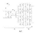
- FIG. 7 depicts an example power converter 420 according to example embodiments of the present disclosure.
- Power converter 420 can be implemented within various suitable wind turbine systems, such as DFIG systems 100 , 300 , and/or other suitable wind turbine system.
- the power converter 420 can correspond to the power converter 168 depicted in FIG. 3 .
- the power converter 420 can be a DC-DC-AC power converter.
- a DC-DC portion 422 of the power converter 420 can correspond to converter 400 depicted in FIG. 6 .
- the DC-DC portion 422 can include a multi-winding transformer 424 having a single winding on a LV side of the power converter 420 and multiple windings (e.g. three windings) on a MV side of the power converter 420 .
- the DC-DC portion 422 can be configured to convert a LV DC power to a MV DC power, and to provide the MV DC power to a DC-AC portion 426 of the power converter 420 .
- the DC-AC portion 426 can convert the MV DC power to a MV AC power suitable for feeding to an AC power system.
- the topologies of the converters 400 and 420 depicted in FIGS. 6 and 7 can facilitate a reduction in the number of transformers used relative to the topology of the power converter 168 depicted in FIG. 3 . Further, the topologies of the converters 400 and 420 can facilitate a reduction in the number of switching devices used relative to the topology of the power converter 168 depicted in FIG. 3 .
Landscapes
- Engineering & Computer Science (AREA)
- Power Engineering (AREA)
- Life Sciences & Earth Sciences (AREA)
- Sustainable Development (AREA)
- Sustainable Energy (AREA)
- Chemical & Material Sciences (AREA)
- Combustion & Propulsion (AREA)
- Mechanical Engineering (AREA)
- General Engineering & Computer Science (AREA)
- Control Of Eletrric Generators (AREA)
- Inverter Devices (AREA)
Abstract
Description
Claims (19)
Priority Applications (5)
| Application Number | Priority Date | Filing Date | Title |
|---|---|---|---|
| US15/399,049 US10439533B2 (en) | 2017-01-05 | 2017-01-05 | Power converter for doubly fed induction generator wind turbine systems |
| US15/663,603 US10641245B2 (en) | 2017-01-05 | 2017-07-28 | Hybrid power generation system and an associated method thereof |
| PCT/US2017/067628 WO2018128819A1 (en) | 2017-01-05 | 2017-12-20 | Power converter for doubly fed induction generator wind turbine systems |
| CN201780088014.5A CN110352552A (en) | 2017-01-05 | 2017-12-20 | Power converter for double fed induction generators formula wind turbine system |
| EP17889707.0A EP3566294B1 (en) | 2017-01-05 | 2017-12-20 | Power converter for doubly fed induction generator wind turbine systems |
Applications Claiming Priority (1)
| Application Number | Priority Date | Filing Date | Title |
|---|---|---|---|
| US15/399,049 US10439533B2 (en) | 2017-01-05 | 2017-01-05 | Power converter for doubly fed induction generator wind turbine systems |
Related Child Applications (1)
| Application Number | Title | Priority Date | Filing Date |
|---|---|---|---|
| US15/663,603 Continuation-In-Part US10641245B2 (en) | 2017-01-05 | 2017-07-28 | Hybrid power generation system and an associated method thereof |
Publications (2)
| Publication Number | Publication Date |
|---|---|
| US20180191280A1 US20180191280A1 (en) | 2018-07-05 |
| US10439533B2 true US10439533B2 (en) | 2019-10-08 |
Family
ID=62711241
Family Applications (1)
| Application Number | Title | Priority Date | Filing Date |
|---|---|---|---|
| US15/399,049 Active US10439533B2 (en) | 2017-01-05 | 2017-01-05 | Power converter for doubly fed induction generator wind turbine systems |
Country Status (4)
| Country | Link |
|---|---|
| US (1) | US10439533B2 (en) |
| EP (1) | EP3566294B1 (en) |
| CN (1) | CN110352552A (en) |
| WO (1) | WO2018128819A1 (en) |
Families Citing this family (3)
| Publication number | Priority date | Publication date | Assignee | Title |
|---|---|---|---|---|
| US20180187652A1 (en) * | 2017-01-05 | 2018-07-05 | General Electric Company | Power Converter for Full Conversion Wind Turbine Systems |
| US11641171B2 (en) * | 2018-08-21 | 2023-05-02 | General Electric Company | System and method for generating a high frequency switching signal for a power converter |
| WO2020233792A1 (en) * | 2019-05-21 | 2020-11-26 | Huawei Technologies Co., Ltd. | High efficiency converter and its control method |
Citations (28)
| Publication number | Priority date | Publication date | Assignee | Title |
|---|---|---|---|---|
| US5719758A (en) | 1995-12-20 | 1998-02-17 | Sharp Kabushiki Kaisha | Inverter control method and inverter apparatus using the method |
| US20030052643A1 (en) | 2001-09-14 | 2003-03-20 | Sweo Edwin A. | Brushless doubly-fed induction machine control |
| US6699987B2 (en) | 1998-12-04 | 2004-03-02 | Invitek Gesellschaft Fur Biotechnik & Biodesign Mbh | Formulations and method for isolating nucleic acids from optional complex starting material and subsequent complex gene analytics |
| US20050012487A1 (en) | 2003-01-23 | 2005-01-20 | Skeist S. Merrill | Doubly fed induction machine |
| US6869640B2 (en) | 2001-06-07 | 2005-03-22 | Tokyo Electron Limited | Coating film forming method and coating film forming apparatus |
| US6924909B2 (en) | 2001-02-20 | 2005-08-02 | Eastman Kodak Company | High-speed scanner having image processing for improving the color reproduction and visual appearance thereof |
| US20060097519A1 (en) * | 2001-12-10 | 2006-05-11 | Jurgen Steinke | Wind energy system, as well as a method for operating such a wind energy system |
| US20090196082A1 (en) * | 2007-12-12 | 2009-08-06 | Mazumder Sudip K | Multiphase Converter Apparatus and Method |
| EP2290799A1 (en) | 2009-08-25 | 2011-03-02 | Converteam Technology Ltd | Bi-directional multilevel AC-DC converter arrangements |
| US20120175962A1 (en) * | 2011-01-11 | 2012-07-12 | Converteam Technology Ltd. | Power Collection and Transmission Systems |
| US20120267955A1 (en) * | 2009-09-08 | 2012-10-25 | Converteam Technology Ltd. | Power transmission and distribution systems |
| US8310102B2 (en) | 2011-03-30 | 2012-11-13 | General Electric Company | System and method for power conversion |
| US20130182465A1 (en) | 2012-01-17 | 2013-07-18 | Delta Electronics (Shanghai) Co., Ltd. | Wind power converter structure and wind power generation system including the same |
| US20130343089A1 (en) * | 2012-06-25 | 2013-12-26 | General Electric Company | Scalable-voltage current-link power electronic system for multi-phase ac or dc loads |
| US8659178B2 (en) | 2009-02-27 | 2014-02-25 | Acciona Windpower, S.A. | Wind turbine control method, control unit and wind turbine |
| EP2709266A2 (en) | 2012-09-13 | 2014-03-19 | General Electric Company | Voltage control in a doubly-fed induction generator wind turbine system |
| US20140078800A1 (en) | 2012-09-14 | 2014-03-20 | General Electric Company | Current balance control in converter for doubly fed induction generator wind turbine system |
| US20150049524A1 (en) * | 2013-08-15 | 2015-02-19 | General Electric Company | Power converter with a multi-level bridge topology and control method |
| US20150070939A1 (en) * | 2013-09-06 | 2015-03-12 | General Electric Company | Electric power conversion system and method of operating the same |
| US20150108761A1 (en) * | 2013-10-18 | 2015-04-23 | Abb Technology Ag | Turbine-Generator System with DC Output |
| US9166495B2 (en) | 2011-06-24 | 2015-10-20 | Abb Technology Ltd. | Wind power converter |
| US20150337808A1 (en) * | 2014-05-22 | 2015-11-26 | Industrial Cooperation Foundation Chonbuk National University | System and method for controlling voltage at point of common coupling of wind farm |
| US20150365031A1 (en) * | 2014-06-13 | 2015-12-17 | Nordex Energy Gmbh | Method for controlling a wind turbine during an asymmetrical grid fault and a wind turbine |
| WO2016066169A1 (en) | 2014-10-27 | 2016-05-06 | Vestas Wind Systems A/S | Wind-turbine converter control for modular string converters |
| US20160261198A1 (en) * | 2015-03-05 | 2016-09-08 | Chengdu Monolithic Power Systems Co., Ltd. | Primary side regulated isolation volatge converter |
| US20160294296A1 (en) * | 2015-04-02 | 2016-10-06 | Virginia Tech Intellectual Properties, Inc. | Universal System Structure for Low Power Adapters |
| US9587626B2 (en) | 2007-06-01 | 2017-03-07 | Acciona Windpower, S.A. | Control system and method for a wind turbine generator |
| US9667457B2 (en) * | 2013-03-28 | 2017-05-30 | Kyocera Corporation | Radio communication device and signal processing method |
Family Cites Families (11)
| Publication number | Priority date | Publication date | Assignee | Title |
|---|---|---|---|---|
| AU2001280040A1 (en) * | 2000-07-31 | 2002-02-13 | Galil Medical Ltd. | Planning and facilitation systems and methods for cryosurgery |
| US8160532B2 (en) * | 2007-01-08 | 2012-04-17 | Skyweaver, Inc. | Community interaction using mobile communication devices |
| CN101795081A (en) * | 2010-03-03 | 2010-08-04 | 中国科学院电工研究所 | Power electronic transformer having multi-winding isolation transformer |
| WO2013171900A1 (en) * | 2012-05-18 | 2013-11-21 | 三菱電機株式会社 | Power supply device |
| US9325251B2 (en) * | 2012-08-30 | 2016-04-26 | Siemens Aktiengesellschaft | Power delivery systems and methods for offshore applications |
| EP2904682B1 (en) | 2012-10-01 | 2017-02-08 | ABB Research Ltd. | Medium voltage dc collection system with power electronics |
| CN104066126B (en) * | 2013-03-18 | 2017-10-20 | 电信科学技术研究院 | A kind of method, system and the equipment of progress D2D switchings |
| US8975768B2 (en) * | 2013-06-05 | 2015-03-10 | General Electic Company | Methods for operating wind turbine system having dynamic brake |
| US8775965B1 (en) * | 2013-06-27 | 2014-07-08 | Google Inc. | Immersive mode for a web browser |
| CN104135164A (en) * | 2014-07-30 | 2014-11-05 | 中国东方电气集团有限公司 | Interleaved parallel multi-level electronic power transformer |
| EP3180849B1 (en) | 2014-08-13 | 2021-11-10 | INESC TEC - Instituto de Engenharia de Sistemas e Computadores, Tecnologia e Ciência | Ac/dc converter with three to single phase matrix converter, full-bridge ac/dc converter and hf transformer |
-
2017
- 2017-01-05 US US15/399,049 patent/US10439533B2/en active Active
- 2017-12-20 EP EP17889707.0A patent/EP3566294B1/en active Active
- 2017-12-20 WO PCT/US2017/067628 patent/WO2018128819A1/en unknown
- 2017-12-20 CN CN201780088014.5A patent/CN110352552A/en active Pending
Patent Citations (28)
| Publication number | Priority date | Publication date | Assignee | Title |
|---|---|---|---|---|
| US5719758A (en) | 1995-12-20 | 1998-02-17 | Sharp Kabushiki Kaisha | Inverter control method and inverter apparatus using the method |
| US6699987B2 (en) | 1998-12-04 | 2004-03-02 | Invitek Gesellschaft Fur Biotechnik & Biodesign Mbh | Formulations and method for isolating nucleic acids from optional complex starting material and subsequent complex gene analytics |
| US6924909B2 (en) | 2001-02-20 | 2005-08-02 | Eastman Kodak Company | High-speed scanner having image processing for improving the color reproduction and visual appearance thereof |
| US6869640B2 (en) | 2001-06-07 | 2005-03-22 | Tokyo Electron Limited | Coating film forming method and coating film forming apparatus |
| US20030052643A1 (en) | 2001-09-14 | 2003-03-20 | Sweo Edwin A. | Brushless doubly-fed induction machine control |
| US20060097519A1 (en) * | 2001-12-10 | 2006-05-11 | Jurgen Steinke | Wind energy system, as well as a method for operating such a wind energy system |
| US20050012487A1 (en) | 2003-01-23 | 2005-01-20 | Skeist S. Merrill | Doubly fed induction machine |
| US9587626B2 (en) | 2007-06-01 | 2017-03-07 | Acciona Windpower, S.A. | Control system and method for a wind turbine generator |
| US20090196082A1 (en) * | 2007-12-12 | 2009-08-06 | Mazumder Sudip K | Multiphase Converter Apparatus and Method |
| US8659178B2 (en) | 2009-02-27 | 2014-02-25 | Acciona Windpower, S.A. | Wind turbine control method, control unit and wind turbine |
| EP2290799A1 (en) | 2009-08-25 | 2011-03-02 | Converteam Technology Ltd | Bi-directional multilevel AC-DC converter arrangements |
| US20120267955A1 (en) * | 2009-09-08 | 2012-10-25 | Converteam Technology Ltd. | Power transmission and distribution systems |
| US20120175962A1 (en) * | 2011-01-11 | 2012-07-12 | Converteam Technology Ltd. | Power Collection and Transmission Systems |
| US8310102B2 (en) | 2011-03-30 | 2012-11-13 | General Electric Company | System and method for power conversion |
| US9166495B2 (en) | 2011-06-24 | 2015-10-20 | Abb Technology Ltd. | Wind power converter |
| US20130182465A1 (en) | 2012-01-17 | 2013-07-18 | Delta Electronics (Shanghai) Co., Ltd. | Wind power converter structure and wind power generation system including the same |
| US20130343089A1 (en) * | 2012-06-25 | 2013-12-26 | General Electric Company | Scalable-voltage current-link power electronic system for multi-phase ac or dc loads |
| EP2709266A2 (en) | 2012-09-13 | 2014-03-19 | General Electric Company | Voltage control in a doubly-fed induction generator wind turbine system |
| US20140078800A1 (en) | 2012-09-14 | 2014-03-20 | General Electric Company | Current balance control in converter for doubly fed induction generator wind turbine system |
| US9667457B2 (en) * | 2013-03-28 | 2017-05-30 | Kyocera Corporation | Radio communication device and signal processing method |
| US20150049524A1 (en) * | 2013-08-15 | 2015-02-19 | General Electric Company | Power converter with a multi-level bridge topology and control method |
| US20150070939A1 (en) * | 2013-09-06 | 2015-03-12 | General Electric Company | Electric power conversion system and method of operating the same |
| US20150108761A1 (en) * | 2013-10-18 | 2015-04-23 | Abb Technology Ag | Turbine-Generator System with DC Output |
| US20150337808A1 (en) * | 2014-05-22 | 2015-11-26 | Industrial Cooperation Foundation Chonbuk National University | System and method for controlling voltage at point of common coupling of wind farm |
| US20150365031A1 (en) * | 2014-06-13 | 2015-12-17 | Nordex Energy Gmbh | Method for controlling a wind turbine during an asymmetrical grid fault and a wind turbine |
| WO2016066169A1 (en) | 2014-10-27 | 2016-05-06 | Vestas Wind Systems A/S | Wind-turbine converter control for modular string converters |
| US20160261198A1 (en) * | 2015-03-05 | 2016-09-08 | Chengdu Monolithic Power Systems Co., Ltd. | Primary side regulated isolation volatge converter |
| US20160294296A1 (en) * | 2015-04-02 | 2016-10-06 | Virginia Tech Intellectual Properties, Inc. | Universal System Structure for Low Power Adapters |
Non-Patent Citations (6)
| Title |
|---|
| Baron et al., Breaking the 34.5kV Standard, Drawing on hydro experience, Acciona extols use of 12kV collection system to lower energy costs through elimination of step-up transformers, Wind Systems Magazine, Apr. 2013, pp. 48-54. |
| International Search Report and Written Opinion issued in connection with corresponding PCT Application No. PCT/US2017/067628 dated Apr. 23, 2018. |
| Islam et al., "Power Converters for Small- to Large-Scale Photovoltaic Power Plants", Power Converters for Medium Voltage Networks, Chapter 2, Springer-Verlag Berlin Heidelberg 2014, pp. 17-49. |
| Olonso Sadaba et al., Wind Generation Control Strategies for Grid Integration Acciona Windpower Experience, ResearchGate, Acciona Windpower, S.A., uploaded 2015, 11 Pages. https://www.researchgate.net/publication/267966410. |
| Wagoner R.G., et al., Power converter for full conversion wind turbine systems, GE Co-Pending U.S. Appl. No. 15/399,067, filed Jan. 5, 2017. |
| Wagoner, R.G., et al., Power Converter for Energy Systems, GE Co-Pending U.S. Appl. No. 15/399,001, filed Jan. 5, 2017. |
Also Published As
| Publication number | Publication date |
|---|---|
| EP3566294B1 (en) | 2024-04-17 |
| CN110352552A (en) | 2019-10-18 |
| EP3566294A4 (en) | 2020-08-12 |
| US20180191280A1 (en) | 2018-07-05 |
| EP3566294A1 (en) | 2019-11-13 |
| WO2018128819A1 (en) | 2018-07-12 |
Similar Documents
| Publication | Publication Date | Title |
|---|---|---|
| US20200158085A1 (en) | Power converter for full conversion wind turbine systems | |
| US8669669B1 (en) | Voltage control in a doubly-fed induction generator wind turbine system | |
| US8476859B2 (en) | DC power for SGCT devices using a high frequency current loop with multiple current transformers | |
| US9018783B2 (en) | Doubly-fed induction generator wind turbine system having solid-state stator switch | |
| US9793788B2 (en) | Energy storage system for renewable energy source | |
| US10103665B2 (en) | Protection for redundancy of isolated inverter blocks | |
| WO2014113146A1 (en) | Connection for improved current balancing between parallel bridge circuits | |
| US20140204630A1 (en) | Current balance control for non-interleaved parallel bridge circuits in power converter | |
| CN110679072B (en) | Switching strategy for improving efficiency of power converter | |
| EP2725701B1 (en) | Current balance control in converter for doubly fed induction generator wind turbine system | |
| EP3566294B1 (en) | Power converter for doubly fed induction generator wind turbine systems | |
| KR20190128712A (en) | Wind farms including a plurality of wind farms | |
| US20180191236A1 (en) | Filter Device for Power Converters with Silicon Carbide Mosfets | |
| CN112292804A (en) | Method for controlling a power converter having an inverter block with silicon carbide MOSFETs |
Legal Events
| Date | Code | Title | Description |
|---|---|---|---|
| AS | Assignment |
Owner name: GENERAL ELECTRIC COMPANY, NEW YORK Free format text: ASSIGNMENT OF ASSIGNORS INTEREST;ASSIGNORS:WAGONER, ROBERT GREGORY;GANIREDDY, GOVARDHAN;SHUKLA, SAURABH;AND OTHERS;SIGNING DATES FROM 20161212 TO 20170104;REEL/FRAME:040860/0641 |
|
| STPP | Information on status: patent application and granting procedure in general |
Free format text: NOTICE OF ALLOWANCE MAILED -- APPLICATION RECEIVED IN OFFICE OF PUBLICATIONS |
|
| STPP | Information on status: patent application and granting procedure in general |
Free format text: DOCKETED NEW CASE - READY FOR EXAMINATION |
|
| STPP | Information on status: patent application and granting procedure in general |
Free format text: NOTICE OF ALLOWANCE MAILED -- APPLICATION RECEIVED IN OFFICE OF PUBLICATIONS |
|
| STPP | Information on status: patent application and granting procedure in general |
Free format text: PUBLICATIONS -- ISSUE FEE PAYMENT VERIFIED |
|
| STCF | Information on status: patent grant |
Free format text: PATENTED CASE |
|
| AS | Assignment |
Owner name: UNITED STATES DEPARTMENT OF ENERGY, DISTRICT OF CO Free format text: CONFIRMATORY LICENSE;ASSIGNOR:GENERAL ELECTRIC GLOBAL RESEARCH CTR;REEL/FRAME:051342/0562 Effective date: 20190502 |
|
| CC | Certificate of correction | ||
| MAFP | Maintenance fee payment |
Free format text: PAYMENT OF MAINTENANCE FEE, 4TH YEAR, LARGE ENTITY (ORIGINAL EVENT CODE: M1551); ENTITY STATUS OF PATENT OWNER: LARGE ENTITY Year of fee payment: 4 |
|
| AS | Assignment |
Owner name: GE INFRASTRUCTURE TECHNOLOGY LLC, SOUTH CAROLINA Free format text: ASSIGNMENT OF ASSIGNORS INTEREST;ASSIGNOR:GENERAL ELECTRIC COMPANY;REEL/FRAME:065727/0001 Effective date: 20231110 |