RU2687055C2 - Pulse power source - Google Patents
Pulse power source Download PDFInfo
- Publication number
- RU2687055C2 RU2687055C2 RU2017107189A RU2017107189A RU2687055C2 RU 2687055 C2 RU2687055 C2 RU 2687055C2 RU 2017107189 A RU2017107189 A RU 2017107189A RU 2017107189 A RU2017107189 A RU 2017107189A RU 2687055 C2 RU2687055 C2 RU 2687055C2
- Authority
- RU
- Russia
- Prior art keywords
- auxiliary
- voltage
- power source
- circuit
- inductor
- Prior art date
Links
Images
Classifications
-
- H—ELECTRICITY
- H02—GENERATION; CONVERSION OR DISTRIBUTION OF ELECTRIC POWER
- H02M—APPARATUS FOR CONVERSION BETWEEN AC AND AC, BETWEEN AC AND DC, OR BETWEEN DC AND DC, AND FOR USE WITH MAINS OR SIMILAR POWER SUPPLY SYSTEMS; CONVERSION OF DC OR AC INPUT POWER INTO SURGE OUTPUT POWER; CONTROL OR REGULATION THEREOF
- H02M3/00—Conversion of dc power input into dc power output
- H02M3/22—Conversion of dc power input into dc power output with intermediate conversion into ac
- H02M3/24—Conversion of dc power input into dc power output with intermediate conversion into ac by static converters
- H02M3/28—Conversion of dc power input into dc power output with intermediate conversion into ac by static converters using discharge tubes with control electrode or semiconductor devices with control electrode to produce the intermediate ac
- H02M3/325—Conversion of dc power input into dc power output with intermediate conversion into ac by static converters using discharge tubes with control electrode or semiconductor devices with control electrode to produce the intermediate ac using devices of a triode or a transistor type requiring continuous application of a control signal
- H02M3/335—Conversion of dc power input into dc power output with intermediate conversion into ac by static converters using discharge tubes with control electrode or semiconductor devices with control electrode to produce the intermediate ac using devices of a triode or a transistor type requiring continuous application of a control signal using semiconductor devices only
- H02M3/33507—Conversion of dc power input into dc power output with intermediate conversion into ac by static converters using discharge tubes with control electrode or semiconductor devices with control electrode to produce the intermediate ac using devices of a triode or a transistor type requiring continuous application of a control signal using semiconductor devices only with automatic control of the output voltage or current, e.g. flyback converters
-
- H—ELECTRICITY
- H02—GENERATION; CONVERSION OR DISTRIBUTION OF ELECTRIC POWER
- H02M—APPARATUS FOR CONVERSION BETWEEN AC AND AC, BETWEEN AC AND DC, OR BETWEEN DC AND DC, AND FOR USE WITH MAINS OR SIMILAR POWER SUPPLY SYSTEMS; CONVERSION OF DC OR AC INPUT POWER INTO SURGE OUTPUT POWER; CONTROL OR REGULATION THEREOF
- H02M3/00—Conversion of dc power input into dc power output
- H02M3/02—Conversion of dc power input into dc power output without intermediate conversion into ac
- H02M3/04—Conversion of dc power input into dc power output without intermediate conversion into ac by static converters
- H02M3/10—Conversion of dc power input into dc power output without intermediate conversion into ac by static converters using discharge tubes with control electrode or semiconductor devices with control electrode
-
- H—ELECTRICITY
- H02—GENERATION; CONVERSION OR DISTRIBUTION OF ELECTRIC POWER
- H02M—APPARATUS FOR CONVERSION BETWEEN AC AND AC, BETWEEN AC AND DC, OR BETWEEN DC AND DC, AND FOR USE WITH MAINS OR SIMILAR POWER SUPPLY SYSTEMS; CONVERSION OF DC OR AC INPUT POWER INTO SURGE OUTPUT POWER; CONTROL OR REGULATION THEREOF
- H02M3/00—Conversion of dc power input into dc power output
- H02M3/22—Conversion of dc power input into dc power output with intermediate conversion into ac
- H02M3/24—Conversion of dc power input into dc power output with intermediate conversion into ac by static converters
- H02M3/28—Conversion of dc power input into dc power output with intermediate conversion into ac by static converters using discharge tubes with control electrode or semiconductor devices with control electrode to produce the intermediate ac
- H02M3/325—Conversion of dc power input into dc power output with intermediate conversion into ac by static converters using discharge tubes with control electrode or semiconductor devices with control electrode to produce the intermediate ac using devices of a triode or a transistor type requiring continuous application of a control signal
- H02M3/335—Conversion of dc power input into dc power output with intermediate conversion into ac by static converters using discharge tubes with control electrode or semiconductor devices with control electrode to produce the intermediate ac using devices of a triode or a transistor type requiring continuous application of a control signal using semiconductor devices only
- H02M3/33561—Conversion of dc power input into dc power output with intermediate conversion into ac by static converters using discharge tubes with control electrode or semiconductor devices with control electrode to produce the intermediate ac using devices of a triode or a transistor type requiring continuous application of a control signal using semiconductor devices only having more than one ouput with independent control
-
- H—ELECTRICITY
- H02—GENERATION; CONVERSION OR DISTRIBUTION OF ELECTRIC POWER
- H02M—APPARATUS FOR CONVERSION BETWEEN AC AND AC, BETWEEN AC AND DC, OR BETWEEN DC AND DC, AND FOR USE WITH MAINS OR SIMILAR POWER SUPPLY SYSTEMS; CONVERSION OF DC OR AC INPUT POWER INTO SURGE OUTPUT POWER; CONTROL OR REGULATION THEREOF
- H02M1/00—Details of apparatus for conversion
- H02M1/08—Circuits specially adapted for the generation of control voltages for semiconductor devices incorporated in static converters
-
- H—ELECTRICITY
- H02—GENERATION; CONVERSION OR DISTRIBUTION OF ELECTRIC POWER
- H02M—APPARATUS FOR CONVERSION BETWEEN AC AND AC, BETWEEN AC AND DC, OR BETWEEN DC AND DC, AND FOR USE WITH MAINS OR SIMILAR POWER SUPPLY SYSTEMS; CONVERSION OF DC OR AC INPUT POWER INTO SURGE OUTPUT POWER; CONTROL OR REGULATION THEREOF
- H02M1/00—Details of apparatus for conversion
- H02M1/14—Arrangements for reducing ripples from dc input or output
-
- H—ELECTRICITY
- H02—GENERATION; CONVERSION OR DISTRIBUTION OF ELECTRIC POWER
- H02M—APPARATUS FOR CONVERSION BETWEEN AC AND AC, BETWEEN AC AND DC, OR BETWEEN DC AND DC, AND FOR USE WITH MAINS OR SIMILAR POWER SUPPLY SYSTEMS; CONVERSION OF DC OR AC INPUT POWER INTO SURGE OUTPUT POWER; CONTROL OR REGULATION THEREOF
- H02M1/00—Details of apparatus for conversion
- H02M1/44—Circuits or arrangements for compensating for electromagnetic interference in converters or inverters
-
- H—ELECTRICITY
- H02—GENERATION; CONVERSION OR DISTRIBUTION OF ELECTRIC POWER
- H02M—APPARATUS FOR CONVERSION BETWEEN AC AND AC, BETWEEN AC AND DC, OR BETWEEN DC AND DC, AND FOR USE WITH MAINS OR SIMILAR POWER SUPPLY SYSTEMS; CONVERSION OF DC OR AC INPUT POWER INTO SURGE OUTPUT POWER; CONTROL OR REGULATION THEREOF
- H02M3/00—Conversion of dc power input into dc power output
- H02M3/02—Conversion of dc power input into dc power output without intermediate conversion into ac
- H02M3/04—Conversion of dc power input into dc power output without intermediate conversion into ac by static converters
- H02M3/10—Conversion of dc power input into dc power output without intermediate conversion into ac by static converters using discharge tubes with control electrode or semiconductor devices with control electrode
- H02M3/145—Conversion of dc power input into dc power output without intermediate conversion into ac by static converters using discharge tubes with control electrode or semiconductor devices with control electrode using devices of a triode or transistor type requiring continuous application of a control signal
- H02M3/155—Conversion of dc power input into dc power output without intermediate conversion into ac by static converters using discharge tubes with control electrode or semiconductor devices with control electrode using devices of a triode or transistor type requiring continuous application of a control signal using semiconductor devices only
-
- H—ELECTRICITY
- H02—GENERATION; CONVERSION OR DISTRIBUTION OF ELECTRIC POWER
- H02M—APPARATUS FOR CONVERSION BETWEEN AC AND AC, BETWEEN AC AND DC, OR BETWEEN DC AND DC, AND FOR USE WITH MAINS OR SIMILAR POWER SUPPLY SYSTEMS; CONVERSION OF DC OR AC INPUT POWER INTO SURGE OUTPUT POWER; CONTROL OR REGULATION THEREOF
- H02M1/00—Details of apparatus for conversion
- H02M1/0003—Details of control, feedback or regulation circuits
- H02M1/0006—Arrangements for supplying an adequate voltage to the control circuit of converters
-
- H—ELECTRICITY
- H02—GENERATION; CONVERSION OR DISTRIBUTION OF ELECTRIC POWER
- H02M—APPARATUS FOR CONVERSION BETWEEN AC AND AC, BETWEEN AC AND DC, OR BETWEEN DC AND DC, AND FOR USE WITH MAINS OR SIMILAR POWER SUPPLY SYSTEMS; CONVERSION OF DC OR AC INPUT POWER INTO SURGE OUTPUT POWER; CONTROL OR REGULATION THEREOF
- H02M1/00—Details of apparatus for conversion
- H02M1/0003—Details of control, feedback or regulation circuits
- H02M1/0009—Devices or circuits for detecting current in a converter
-
- H—ELECTRICITY
- H02—GENERATION; CONVERSION OR DISTRIBUTION OF ELECTRIC POWER
- H02M—APPARATUS FOR CONVERSION BETWEEN AC AND AC, BETWEEN AC AND DC, OR BETWEEN DC AND DC, AND FOR USE WITH MAINS OR SIMILAR POWER SUPPLY SYSTEMS; CONVERSION OF DC OR AC INPUT POWER INTO SURGE OUTPUT POWER; CONTROL OR REGULATION THEREOF
- H02M1/00—Details of apparatus for conversion
- H02M1/0067—Converter structures employing plural converter units, other than for parallel operation of the units on a single load
- H02M1/0074—Plural converter units whose inputs are connected in series
Abstract
Description
Область техники, к которой относится изобретениеThe technical field to which the invention relates.
Настоящее раскрытие относится к импульсному источнику питания, имеющему вспомогательную схему для подачи вспомогательного выходного напряжения.The present disclosure relates to a switching power supply having an auxiliary circuit for supplying an auxiliary output voltage.
Уровень техникиThe level of technology
Импульсные источники питания представляют собой электронные схемы, преобразующие напряжение и ток источника электроэнергии посредством ключа, такого как транзистор. Малые габариты и высокие КПД делают их пригодными для самых разнообразных применений. Например, бытовые электронные приборы, такие как зарядные устройства для мобильных телефонов и блоки питания для портативных компьютеров, обычно включают в себя импульсный источник питания для преобразования переменного тока сети электропитания в постоянный ток, необходимый для нагрузки. Switching power supplies are electronic circuits that convert the voltage and current of a source of electrical energy through a key, such as a transistor. Small size and high efficiency make them suitable for a wide variety of applications. For example, consumer electronics devices, such as mobile phone chargers and laptop power supplies, typically include a switching power supply for converting AC mains power to direct current required for a load.
В дополнение к преобразованному напряжению импульсные источники питания часто выполнены с возможностью вырабатывать низкое вспомогательное напряжение для возбуждения ключа или некоторого другого компонента. В документе US 2011/0157919 A1 раскрыт пример того, как вырабатывается напряжение питания для интегральной схемы, используемой для управления системой регулирования переключающего напряжения. Желательно, чтобы эта выработка напряжения была энергоэффективной и недорогой в реализации. In addition to the converted voltage, switching power supplies are often configured to produce a low auxiliary voltage for driving a key or some other component. Document US 2011/0157919 A1 discloses an example of how the supply voltage is generated for an integrated circuit used to control the switching voltage control system. It is desirable that this voltage generation be energy efficient and inexpensive to implement.
Сущность изобретенияSummary of Invention
Общая задача настоящего изобретения состоит в том, чтобы выполнить усовершенствованный или альтернативный импульсный источник питания. Конкретные задачи включают в себя выполнение недорогой и энергоэффективной вспомогательной схемы, которая обеспечивает вспомогательное напряжение для компонента импульсного источника питания или для отдельной схемы, такой как контроллер для драйвера светоизлучающего диода. The overall objective of the present invention is to provide an improved or alternative switching power supply. Specific tasks include performing an inexpensive and energy-efficient auxiliary circuit that provides an auxiliary voltage for a component of a switching power supply or for a separate circuit, such as a controller for a light emitting diode driver.
Изобретение ограничено независимым пунктом формулы изобретения. Варианты осуществления изложены в зависимых пунктах формулы изобретения и описании и показаны на чертежах. The invention is limited to the independent claim. The embodiments are set forth in the dependent claims and the description and shown in the drawings.
Согласно первому аспекту выполнен импульсный источник питания, содержащий основную схему, которая выполнена с возможностью приема постоянного входного напряжения и подачи постоянного выходного напряжения, и вспомогательную схему, которая выполнена с возможностью подачи вспомогательного напряжения. Основная схема содержит: индуктивный элемент для подачи постоянного выходного напряжения, переключающий элемент, соединенный с индуктивным элементом, и контроллер, выполненный с возможностью переключения переключающего элемента между проводящим состоянием и непроводящим состоянием. Переключающий элемент выполнен с возможностью подачи пульсирующего постоянного тока на потенциал земли. Вспомогательная схема содержит вспомогательный индуктор, подключенный для приема пульсирующего постоянного тока, и магнитно изолирован от индуктивного элемента. Следовательно, вспомогательный индуктор магнитно не связан с индуктивным элементом.According to the first aspect, there is a switching power supply comprising a main circuit that is configured to receive a constant input voltage and supply a constant output voltage, and an auxiliary circuit that is configured to supply an auxiliary voltage. The main circuit contains: an inductive element for supplying a constant output voltage, a switching element connected to the inductive element, and a controller configured to switch the switching element between a conducting state and a non-conducting state. The switching element is adapted to supply a pulsating direct current to the earth potential. The auxiliary circuit contains an auxiliary inductor connected to receive a pulsating direct current and is magnetically isolated from the inductive element. Therefore, the auxiliary inductor is not magnetically connected to the inductive element.
Под фразой "пульсирующий постоянный ток" подразумевается постоянный ток, имеющий переменную амплитуду. Аббревиатуры "AC" и "DC" обозначают "переменный ток" и "постоянный ток", соответственно. Вспомогательное напряжение представляет собой обычно постоянное напряжение, имеющее по существу постоянную амплитуду. Постоянное входное напряжение представляет собой обычно выпрямленное и буферное переменное напряжение. By the phrase "pulsating direct current" is meant a direct current having a variable amplitude. The abbreviations "AC" and "DC" stand for "alternating current" and "direct current", respectively. The auxiliary voltage is usually a constant voltage having a substantially constant amplitude. A constant input voltage is usually rectified and buffered alternating voltage.
Так как основной и вспомогательный индукторы магнитно изолированы, устройство, описанное выше, можно реализовать, используя недорогой основный индуктор, такой как цилиндрический индуктор с сердечником, и маленький вспомогательный индуктор, например, индуктор поверхностного монтажа. Вспомогательная схема может быть простой и энергоэффективной. Since the main and auxiliary inductors are magnetically isolated, the device described above can be implemented using an inexpensive basic inductor, such as a cylindrical inductor with a core, and a small auxiliary inductor, such as a surface-mounted inductor. An auxiliary circuit can be simple and energy efficient.
Согласно одному варианту осуществления импульсного источника питания, основные схемы и вспомогательные схемы подключены к общей земле. Вспомогательный индуктор может быть подключен, например, к потенциалу земли и к постоянному входному напряжению отрицательной полярности. Для некоторых приложений преимущественным является подключение основных схем и вспомогательных схем к общей земле, так как в иных случаях может возникнуть необходимость использования схемы сдвига уровня.According to one embodiment of the pulsed power supply, the main circuits and auxiliary circuits are connected to a common ground. The auxiliary inductor can be connected, for example, to the ground potential and to a constant input voltage of negative polarity. For some applications, it is preferable to connect the main circuits and auxiliary circuits to the common ground, since in other cases it may be necessary to use a level-shift circuit.
Согласно предпочтительному варианту осуществления импульсного источника питания вспомогательная схема содержит: конденсатор, подключенный к потенциалу земли, и диод, подключенный к вспомогательному индуктору и конденсатору, где вспомогательным напряжением является напряжение на конденсаторе. Диод может быть недорогим низковольтным диодом. Для того чтобы ограничить вспомогательное напряжение, параллельно конденсатору можно включить стабилитрон. Чтобы уменьшить колебания во вспомогательной схеме, демпфирующий резистор можно соединить параллельно вспомогательному индуктору. According to a preferred embodiment of the pulsed power source, the auxiliary circuit comprises: a capacitor connected to the ground potential and a diode connected to the auxiliary inductor and a capacitor, where the auxiliary voltage is the voltage across the capacitor. A diode can be an inexpensive low-voltage diode. In order to limit the auxiliary voltage, a zener diode can be switched on parallel to the capacitor. To reduce oscillation in the auxiliary circuit, the damping resistor can be connected in parallel to the auxiliary inductor.
Согласно одному варианту осуществления импульсного источника питания, индуктивным элементом является индуктор. Таким образом, индуктивный элемент может содержать одну катушку или обмотку. В альтернативном варианте осуществления индуктивным элементом является трансформатор, имеющий две магнитно-связанные катушки. According to one embodiment of the pulsed power supply, the inductor is an inductor. Thus, the inductive element can contain one coil or a winding. In an alternative embodiment, the inductive element is a transformer having two magnetically coupled coils.
Согласно одному варианту осуществления импульсного источника питания, запускающий резистор подключен к контроллеру и к шине положительной полярности постоянного входного напряжения. Это позволяет улучшить характеристики запуска импульсного источника питания.According to one embodiment of the switching power supply, the triggering resistor is connected to the controller and to the positive polarity bus of the DC input voltage. This allows you to improve the start-up characteristics of a switching power supply
Согласно одному варианту осуществления импульсного источника питания, вспомогательное напряжение подключено к основной схеме. Альтернативно, вспомогательное напряжение подключено к нагрузке, расположенной за пределами основной и вспомогательной схем.According to one embodiment of the switching power supply, the auxiliary voltage is connected to the main circuit. Alternatively, the auxiliary voltage is connected to a load located outside the main and auxiliary circuits.
Следует отметить, что изобретение относится ко всем возможным комбинациям признаков, изложенных в формуле изобретения.It should be noted that the invention relates to all possible combinations of features set forth in the claims.
Краткое описание чертежейBrief Description of the Drawings
Этот и другие аспекты настоящего изобретения будут теперь описаны более подробно, со ссылкой на прилагаемые чертежи, показывающие вариант(ы) осуществления изобретения. Одинаковые ссылочные позиции относятся к одинаковым элементам на протяжении всего описания.This and other aspects of the present invention will now be described in more detail with reference to the accompanying drawings showing the embodiment (s) of the invention. The same reference numbers refer to the same elements throughout the description.
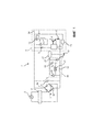
Фиг.1 иллюстрирует принципиальную электрическую схему варианта осуществления импульсного источника питания.Figure 1 illustrates a circuit diagram of an embodiment of a switching power supply.
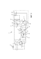
Фиг.2 иллюстрирует принципиальную электрическую схему варианта осуществления импульсного источника питания, имеющего трансформатор.2 illustrates a circuit diagram of an embodiment of a switching power supply having a transformer.
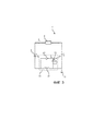
Фиг.3 иллюстрирует принципиальную электрическую схему, показывающую протекание тока во время работы в варианте осуществления импульсного источника питания.Figure 3 illustrates a circuit diagram showing the flow of current during operation in an embodiment of a pulsed power source.
Подробное описание изобретенияDetailed Description of the Invention
Настоящее изобретение будет описано ниже более подробно со ссылками на прилагаемые чертежи, на которых показаны предпочтительные в настоящее время варианты осуществления изобретения. Однако настоящее изобретение может быть воплощено во многих различных формах и не должно быть истолковано как ограниченное вариантами осуществления, изложенными в данном документе; напротив, эти варианты осуществления предназначены для обеспечения полноты и завершенности раскрытия и полной передачи объема изобретения специалистам в данной области техники.The present invention will be described in more detail below with reference to the accompanying drawings, in which presently preferred embodiments of the invention are shown. However, the present invention may be embodied in many different forms and should not be construed as limited to the embodiments set forth herein; on the contrary, these embodiments are intended to ensure the completeness and completeness of the disclosure and full transfer of the scope of the invention to those skilled in the art.
Фиг.1 иллюстрирует принципиальную электрическую схему импульсного источника 1 питания, подключенного к источнику 2 электроэнергии, который представляет собой источник переменного тока, который обеспечивает подачу переменного входного напряжения на импульсный источник 1 питания. В качестве примера, источник 2 электроэнергии представляет собой сеть электропитания, обеспечивающую подачу переменного входного напряжения, имеющего амплитуду между 100 В и 240 В и частоту 50 Гц или rectifier 60 Гц. Источник 2 электроэнергии подключен к выпрямителю 3 обычно через фильтр 4, такой как фильтр подавления электромагнитных помех. Фильтр 4 позволяет уменьшать шумовые помехи от источника 2 электроэнергии, и тем самым обеспечить защиту чувствительным компонентам в импульсном источнике 1 питания. Выпрямитель 3 является диодным мостовым выпрямителем и, более конкретно, двухполупериодным выпрямителем типа "диодный мост". Однако однополупериодное выпрямление является применяемой альтернативой. Выпрямитель 3 имеет положительный вывод 3a и отрицательный вывод 3b, при этом разность потенциалов между выводами 3a, 3b равна постоянному входному напряжению V1. Импульсный источник питания дополнительно содержит входной конденсатор 5, который подключен к шине положительной полярности постоянного входного напряжения V1 через положительный вывод 3a и к шине отрицательной полярности постоянного входного напряжения V1 через отрицательный вывод 3b. Емкость входного конденсатора 5 может находиться, например, в диапазоне от приблизительно 1 мкФ до приблизительно 100 мкФ. Постоянное входное напряжение V1 имеет пульсации, которые сглаживаются посредством входного конденсатора 5. Согласно другому варианту осуществления импульсный источник 1 питания предназначен для подключения к источнику 2 электроэнергии, обеспечивающему подачу постоянного входного напряжения, и затем выпрямитель 3 исключен. FIG. 1 illustrates a circuit diagram of a
Импульсный источник 1 питания имеет основную схему 6, выполненную с возможностью приема постоянного входного напряжение V1 и подачи постоянного выходного напряжения V2 для питания электронных устройств, например, лампочки или компьютера. Значение выходного напряжения V2 зависит от предполагаемого применения, но обычно находится в диапазоне приблизительно от 20 В до приблизительно 140 В. Таким образом, основная схема 6 может работать как преобразователь постоянного тока в постоянный (DC/DC-преобразователь), такой как понижающий преобразователь или повышающий преобразователь. Основная схема 6 имеет контроллер 7, например, контроллер широтно-импульсной модуляции, который, подключен к положительному выводу 3a. Контроллер 7 подключен к положительному выводу 3a через запускающий резистор 8. Следовательно, запускающий резистор 8 подключен к контроллеру 7 и шине постоянного входного напряжения V1 положительной полярности. Например, сопротивление запускающего резистора 8 может находиться в диапазоне приблизительно от 100 кОм до приблизительно 1 МОм. Согласно другому варианту осуществления запускающий резистор 8 исключен. The
Контроллер 7 подключен к переключающему элементу 9, причем контроллер 7 выполнен с возможностью переключения переключающего элемента 9 между проводящим состоянием и непроводящим состоянием. В данном варианте осуществления переключающим элементом 9 является транзистор. Переключающим элементом 9 может быть биполярный транзистор, такой как p-n-p транзистор или n-p-n транзистор. Переключающим элементом 9 может быть полевой транзистор, такой как МОП-транзистор. Переключающим элементом 9 может быть тиристор, запираемый тиристор (GTO) или биполярный транзистор с изолированным затвором (IGBT) и т.д. Переключающий элемент 9 выполнен с возможностью подачи пульсирующего постоянного тока на потенциал 10 земли. Переключающий элемент 9 можно подсоединить к потенциалу 10 земли через токочувствительный резистор 11 для текущего измерения. Токочувствительный резистор 11 подсоединен к эмиттеру переключающего элемента 9 и обычно имеет сопротивление больше, чем приблизительно 100 мОм. Переключающий элемент 9 подсоединен к индуктивному элементу 12 в виде индуктора. Более точно, индуктивным элементом 12 является индуктор, содержащий одну обмотку. Индуктивный элемент 12 подсоединен к коллектору переключающего элемента 9. Индуктивность индуктивного элемента 12 может находиться, например, в диапазоне от приблизительно 200 мкГн до приблизительно 10 мГн. Индуктивный элемент 12 обеспечивает подачу постоянного выходного напряжения V2 путем накопления энергии, которая преобразуется в выходной сигнал основной схемы 6 в течение каждого цикла переключения с целью выработки выходного напряжения V2. The controller 7 is connected to the
Основная схема 6 обычно включает в себя и другие компоненты. Согласно варианту осуществления, показанному на фиг.1, индуктивный элемент 12 подсоединен к положительному выводу 3a через выходной конденсатор 13, соединенный последовательно с индуктивным элементом 12. Постоянное выходное напряжение V2 представляет собой напряжение на выходном конденсаторе 13. Основная схема 6 выполнена с выходными выводами 24 для подключения внешней нагрузки к выходному напряжению V2. Блокировочный диод 14, который предотвращает разряд выходного конденсатора 13 через переключающий элемент 9 во время работы импульсного источника 1 питания, соединен параллельно с выходным конденсатором 13 и индуктивным элементом 12. Схема 15 обратной связи, предназначенная для контроля постоянного выходного напряжения V2, подключена к контроллеру 7. Например, схему 15 обратной связи можно выполнить с возможностью подачи сигнала в контроллер 7 в случае, если отклонение постоянного выходного напряжения V2 от опорного напряжения становится больше заданного значения. Исключение схемы 15 обратной связи является возможной альтернативой. The
Импульсный источник 1 питания имеет вспомогательную схему 16, которая выполнена с возможностью подачи вспомогательного напряжения V3. Вспомогательным напряжением V3 обычно является постоянное напряжение, имеющее постоянную амплитуду или по существу постоянную амплитуду. Например, вспомогательное напряжение V3 может находиться в диапазоне от приблизительно 5 В до приблизительно 12 В. Вспомогательное напряжение V3 подается на нагрузку 17 через один или более вспомогательных выходных выводов 23. Нагрузка 17 подключена к потенциалу 10 земли, то есть к тому же самому потенциалу земли, как и основная схема 6. Однако, в общем случае, нагрузка 17 не обязательно должна быть подключена к тому же самому потенциалу земли, как и основная схема 6. Примерами обычных нагрузок 17 служат схемы управления, микропроцессоры, фотоэлектрические датчики, пассивные инфракрасные датчики или контроллеры для драйверов светоизлучающих диодов. Нагрузка 17 может быть компонентом импульсного источника 1 питания. Например, основная схема 6 может быть подключена к шине вспомогательного напряжения V3 таким образом, чтобы вспомогательное напряжение V3 возбуждало контроллер 7. Альтернативно, нагрузка 17 находится за пределами импульсного источника 1 питания, то есть нагрузка 17 образует часть схемы, которая не включена в импульсный источник 1 питания. The switching
Вспомогательная схема 16 имеет вспомогательный индуктор 18, который подключен для приема импульсного постоянного тока, вырабатываемого переключающим элементом 9. Индуктивность вспомогательного индуктора 18 обычно гораздо меньше, чем индуктивность индуктивного элемента. Согласно некоторым вариантам осуществления, индуктивность вспомогательного индуктора 18 находится в диапазоне от приблизительно 10 мкГн до приблизительно 500 мГн. Вспомогательный индуктор 18 и индуктивный элемент 12 магнитно изолированы друг от друга, то есть вспомогательный индуктор 18 и индуктивный элемент 12 не связаны. Вспомогательный индуктор 18 подсоединен к потенциалу 10 земли и отрицательному выводу 3b таким образом, чтобы вспомогательная схема 16 и основная схема 6 были подсоединены к общему потенциалу земли. The
Вспомогательная схема 16 имеет конденсатор 19, подсоединенный к потенциалу 10 земли. Вспомогательное напряжение V3 представляет собой напряжение на конденсаторе 19. Вспомогательная схема 16 также имеет диод 20, подсоединенный к вспомогательному индуктору 18 и конденсатору 19. Диод 20 может быть полупроводниковым диодом. Вспомогательная схема 16 имеет демпфирующий резистор 21, включенный параллельно вспомогательному индуктору 18. Стабилитрон 22, предназначенный для ограничения вспомогательного напряжения V3, включен параллельно конденсатору 19. Другие варианты осуществления вспомогательной схемы 16 не включают в себя демпфирующий резистор 21 и/или стабилитрон 22.
Фиг.2 иллюстрирует принципиальную электрическую схему импульсного источника 1 питания, которая аналогична импульсному источнику 1 питания, показанному на фиг.1. Однако в этом примере, индуктивным элементом 12 является трансформатор, имеющий две магнитно-связанные катушки провода.FIG. 2 illustrates a circuit diagram of a
На фиг.3 показана принципиальная электрическая схема импульсного источника 1 питания, иллюстрирующая протекание тока, показанного стрелками. Во время работы импульсного источника 1 питания, постоянное входное напряжение V1, подаваемое на входной конденсатор 5, приводит к протеканию входного тока I1 со стороны положительной полярности входного конденсатора 5 в основную схему 6, в результате чего контроллер 7 начинает переключать переключающий элемент 9 между проводящим состоянием и непроводящим состоянием. Запускающий резистор 8 может оказывать помощь в запуске контроллера 7. Переключение приводит к возникновению импульсного постоянного тока I2, протекающего из переключающего элемента 9 в потенциал 10 земли и во вспомогательный индуктор 18. Когда переключающий элемент 9 находится в проводящем состоянии, вспомогательный индуктор 18 заряжается с помощью импульсного постоянного тока I2. Переключение переключающего элемента 9 в непроводящее состояние приводит к падению амплитуды импульсного постоянного тока I2, в результате чего вырабатывается индуцированный ток I3. Индуцированный ток I3 протекает во вспомогательной схеме 16 через диод 20 в конденсатор 19 таким образом, чтобы заряжался конденсатор 19. Величина заряда, подаваемого в конденсатор 19, зависит от индуктивности вспомогательного индуктора 18, интенсивности выходного тока I2 и частоты переключения переключающего элемента 9. Диод 20 предотвращает разряд конденсатора 19 в тот момент, когда переключающий элемент 9 переключается обратно в проводящее состояние. Процесс переключения приводит к возникновению вспомогательного напряжения V3, вырабатываемого на конденсаторе 19.Figure 3 shows the circuit diagram of a
Специалисту в данной области техники будет понятно, что настоящее изобретение никоим образом не ограничивается предпочтительными вариантами осуществления, описанными выше. Напротив, многие модификации и вариации возможны в пределах объема прилагаемой формулы изобретения. Например, согласно некоторым вариантам осуществления основная схема 6 и вспомогательная схема 16 не подсоединены к общему потенциалу земли. В дальнейшем может потребоваться использование схемы сдвига уровня.It will be clear to a person skilled in the art that the present invention is in no way limited to the preferred embodiments described above. On the contrary, many modifications and variations are possible within the scope of the appended claims. For example, in some embodiments, the
Кроме того, изменения в раскрытых вариантах осуществления могут быть понятны и осуществлены специалистами в данной области техники при реализации заявленного изобретения, из изучения чертежей, раскрытия и прилагаемой формулы изобретения. В пунктах формулы изобретения слово "содержащий" не исключает другие элементы или этапы, и единственное число не исключает множественность. Тот факт, что конкретные меры излагаются во взаимно различных зависимых пунктах формулы изобретения, не указывает на то, что сочетание этих мер не может быть использовано для преимущества.In addition, changes in the disclosed embodiments can be understood and made by those skilled in the art in implementing the claimed invention, from a study of the drawings, the disclosure and the appended claims. In the claims, the word "comprising" does not exclude other elements or steps, and the singular does not exclude a plurality. The fact that specific measures are set out in mutually different dependent claims does not indicate that a combination of these measures cannot be used to advantage.
Claims (18)
Applications Claiming Priority (3)
| Application Number | Priority Date | Filing Date | Title |
|---|---|---|---|
| EP14180185 | 2014-08-07 | ||
| EP14180185.2 | 2014-08-07 | ||
| PCT/EP2015/067357 WO2016020235A2 (en) | 2014-08-07 | 2015-07-29 | Switch-mode power supply |
Publications (3)
| Publication Number | Publication Date |
|---|---|
| RU2017107189A RU2017107189A (en) | 2018-09-07 |
| RU2017107189A3 RU2017107189A3 (en) | 2019-03-05 |
| RU2687055C2 true RU2687055C2 (en) | 2019-05-07 |
Family
ID=51266216
Family Applications (1)
| Application Number | Title | Priority Date | Filing Date |
|---|---|---|---|
| RU2017107189A RU2687055C2 (en) | 2014-08-07 | 2015-07-29 | Pulse power source |
Country Status (6)
| Country | Link |
|---|---|
| US (1) | US20170229970A1 (en) |
| EP (1) | EP3178157A2 (en) |
| JP (1) | JP2017524328A (en) |
| CN (1) | CN106664013A (en) |
| RU (1) | RU2687055C2 (en) |
| WO (1) | WO2016020235A2 (en) |
Families Citing this family (1)
| Publication number | Priority date | Publication date | Assignee | Title |
|---|---|---|---|---|
| US10523042B2 (en) | 2017-05-12 | 2019-12-31 | Qualcomm Incorporated | Master-slave charging circuit with slave charger input current sensing and adaptive battery current limiting |
Citations (4)
| Publication number | Priority date | Publication date | Assignee | Title |
|---|---|---|---|---|
| RU2095927C1 (en) * | 1995-02-17 | 1997-11-10 | Андрей Васильевич Щукин | Commutator for direct voltage converter |
| WO2001018946A1 (en) * | 1999-09-03 | 2001-03-15 | Lambda Electronics | Inductor current sensing |
| US20080049452A1 (en) * | 2004-10-28 | 2008-02-28 | Koninklijke Philips Electronics, N.V. | Ultralow Power stan-By Supply |
| US20140119058A1 (en) * | 2012-10-30 | 2014-05-01 | Chicony Power Technology Co., Ltd. | Power voltage conversion system for controller integrated circuit |
Family Cites Families (5)
| Publication number | Priority date | Publication date | Assignee | Title |
|---|---|---|---|---|
| JPH08182309A (en) * | 1994-12-22 | 1996-07-12 | Hitachi Lighting Ltd | Chopper |
| JP2005051845A (en) * | 2003-07-30 | 2005-02-24 | Ushio Inc | Dc-dc converter and high-pressure discharge lamp lighting device using it |
| CN201022180Y (en) * | 2006-11-28 | 2008-02-13 | 尼克森微电子股份有限公司 | First side feedback controlled exchange power supplier |
| US8198874B2 (en) * | 2009-06-30 | 2012-06-12 | Cirrus Logic, Inc. | Switching power converter with current sensing transformer auxiliary power supply |
| US9735663B2 (en) * | 2013-02-20 | 2017-08-15 | Power Integrations, Inc. | BJT drive scheme |
-
2015
- 2015-07-29 EP EP15744201.3A patent/EP3178157A2/en not_active Withdrawn
- 2015-07-29 CN CN201580042430.2A patent/CN106664013A/en active Pending
- 2015-07-29 RU RU2017107189A patent/RU2687055C2/en not_active IP Right Cessation
- 2015-07-29 JP JP2017506783A patent/JP2017524328A/en active Pending
- 2015-07-29 WO PCT/EP2015/067357 patent/WO2016020235A2/en active Application Filing
- 2015-07-29 US US15/501,876 patent/US20170229970A1/en not_active Abandoned
Patent Citations (4)
| Publication number | Priority date | Publication date | Assignee | Title |
|---|---|---|---|---|
| RU2095927C1 (en) * | 1995-02-17 | 1997-11-10 | Андрей Васильевич Щукин | Commutator for direct voltage converter |
| WO2001018946A1 (en) * | 1999-09-03 | 2001-03-15 | Lambda Electronics | Inductor current sensing |
| US20080049452A1 (en) * | 2004-10-28 | 2008-02-28 | Koninklijke Philips Electronics, N.V. | Ultralow Power stan-By Supply |
| US20140119058A1 (en) * | 2012-10-30 | 2014-05-01 | Chicony Power Technology Co., Ltd. | Power voltage conversion system for controller integrated circuit |
Also Published As
| Publication number | Publication date |
|---|---|
| RU2017107189A (en) | 2018-09-07 |
| US20170229970A1 (en) | 2017-08-10 |
| WO2016020235A3 (en) | 2016-03-31 |
| JP2017524328A (en) | 2017-08-24 |
| CN106664013A (en) | 2017-05-10 |
| EP3178157A2 (en) | 2017-06-14 |
| RU2017107189A3 (en) | 2019-03-05 |
| WO2016020235A2 (en) | 2016-02-11 |
Similar Documents
| Publication | Publication Date | Title |
|---|---|---|
| TWI501533B (en) | An off-line voltage regulator, off-line regulator integrated circuit and voltage convert method thereof | |
| US8194417B2 (en) | Two-stage switching power supply | |
| CA2373762C (en) | Method and apparatus for converting a dc voltage to an ac voltage | |
| US11095209B2 (en) | Power supply control circuit, power supply device and electronic apparatus | |
| CN100418293C (en) | Capacitively coupled power supply | |
| US9263944B2 (en) | Valley-fill power factor correction circuit with active conduction angle control | |
| Chen et al. | A novel primary-side controlled universal-input AC–DC LED driver based on a source-driving control scheme | |
| KR20100092395A (en) | Circuit arrangement for conversion of an input ac voltage to a dc voltage, retrofit lamp having a circuit arrangment such as this, as well as a lighting system | |
| KR20130085904A (en) | Dynamic damper and lighting driving circuit comprising the dynamic damper | |
| US20160043626A1 (en) | Power supply source for an electric heating system | |
| US20130170253A1 (en) | Auxiliary power generation circuit | |
| RU2687055C2 (en) | Pulse power source | |
| TWI419450B (en) | A system and method for reducing the standby power consumption of a switch mode power converter | |
| JP2004350361A (en) | Switching power supply | |
| TWI586092B (en) | Single-stage ac-to-dc converter | |
| JP2017063570A (en) | Power supply device | |
| JP2006500899A (en) | Apparatus and method for converting alternating voltage | |
| KR101739755B1 (en) | LED driving circuit | |
| JP2013251528A (en) | Light-emitting diode drive circuit | |
| JP2011120466A (en) | Power regeneration device | |
| CN116707281B (en) | Harmonic suppression circuit, power supply circuit and power supply adapter | |
| Hou et al. | On-chip accurate primary-side output current estimator for flyback LED driver control | |
| CN220421638U (en) | Voltage conversion circuit and electronic equipment | |
| JP2736059B2 (en) | Inverter device | |
| Bharadwaj et al. | High Voltage Boost Converters: A Review on Different Methodologies and Topologies |
Legal Events
| Date | Code | Title | Description |
|---|---|---|---|
| MM4A | The patent is invalid due to non-payment of fees |
Effective date: 20200730 |