RU2504355C2 - Wound bandage - Google Patents
Wound bandage Download PDFInfo
- Publication number
- RU2504355C2 RU2504355C2 RU2010151858/14A RU2010151858A RU2504355C2 RU 2504355 C2 RU2504355 C2 RU 2504355C2 RU 2010151858/14 A RU2010151858/14 A RU 2010151858/14A RU 2010151858 A RU2010151858 A RU 2010151858A RU 2504355 C2 RU2504355 C2 RU 2504355C2
- Authority
- RU
- Russia
- Prior art keywords
- rod
- wound dressing
- shaped elements
- dressing according
- cell
- Prior art date
Links
- 206010052428 Wound Diseases 0.000 claims abstract description 83
- 208000027418 Wounds and injury Diseases 0.000 claims abstract description 83
- 206010030113 Oedema Diseases 0.000 claims abstract description 16
- 238000000034 method Methods 0.000 claims abstract description 11
- 241001465754 Metazoa Species 0.000 claims abstract description 7
- 238000009432 framing Methods 0.000 claims description 19
- 230000002980 postoperative effect Effects 0.000 claims description 15
- 239000008280 blood Substances 0.000 claims description 8
- 210000004369 blood Anatomy 0.000 claims description 8
- 239000000463 material Substances 0.000 claims description 8
- 230000001276 controlling effect Effects 0.000 claims description 4
- 239000004033 plastic Substances 0.000 claims description 4
- 229920003023 plastic Polymers 0.000 claims description 4
- 230000001105 regulatory effect Effects 0.000 claims description 4
- 238000003825 pressing Methods 0.000 claims description 2
- 230000015572 biosynthetic process Effects 0.000 claims 1
- 239000012528 membrane Substances 0.000 claims 1
- 208000032843 Hemorrhage Diseases 0.000 abstract 3
- 239000003814 drug Substances 0.000 abstract 1
- 230000000694 effects Effects 0.000 abstract 1
- 239000000126 substance Substances 0.000 abstract 1
- 210000003128 head Anatomy 0.000 description 26
- 230000007423 decrease Effects 0.000 description 8
- 206010042674 Swelling Diseases 0.000 description 4
- 239000013013 elastic material Substances 0.000 description 4
- 230000008961 swelling Effects 0.000 description 4
- 239000012530 fluid Substances 0.000 description 3
- 230000000740 bleeding effect Effects 0.000 description 2
- 238000011084 recovery Methods 0.000 description 2
- 239000002210 silicon-based material Substances 0.000 description 2
- 206010019196 Head injury Diseases 0.000 description 1
- 239000004743 Polypropylene Substances 0.000 description 1
- 239000004793 Polystyrene Substances 0.000 description 1
- 208000002847 Surgical Wound Diseases 0.000 description 1
- 238000009825 accumulation Methods 0.000 description 1
- XECAHXYUAAWDEL-UHFFFAOYSA-N acrylonitrile butadiene styrene Chemical compound C=CC=C.C=CC#N.C=CC1=CC=CC=C1 XECAHXYUAAWDEL-UHFFFAOYSA-N 0.000 description 1
- 229920000122 acrylonitrile butadiene styrene Polymers 0.000 description 1
- 239000004676 acrylonitrile butadiene styrene Substances 0.000 description 1
- 230000017531 blood circulation Effects 0.000 description 1
- 210000005069 ears Anatomy 0.000 description 1
- 229920002457 flexible plastic Polymers 0.000 description 1
- 210000001061 forehead Anatomy 0.000 description 1
- 239000003292 glue Substances 0.000 description 1
- 238000000465 moulding Methods 0.000 description 1
- 239000011505 plaster Substances 0.000 description 1
- 229920000642 polymer Polymers 0.000 description 1
- -1 polypropylene Polymers 0.000 description 1
- 229920001155 polypropylene Polymers 0.000 description 1
- 229920002223 polystyrene Polymers 0.000 description 1
- 230000001681 protective effect Effects 0.000 description 1
- 210000004761 scalp Anatomy 0.000 description 1
- 238000007789 sealing Methods 0.000 description 1
- 208000037974 severe injury Diseases 0.000 description 1
- 230000009528 severe injury Effects 0.000 description 1
- 238000001356 surgical procedure Methods 0.000 description 1
- 239000012815 thermoplastic material Substances 0.000 description 1
- 238000003466 welding Methods 0.000 description 1
- 230000029663 wound healing Effects 0.000 description 1
Images
Classifications
-
- A—HUMAN NECESSITIES
- A61—MEDICAL OR VETERINARY SCIENCE; HYGIENE
- A61F—FILTERS IMPLANTABLE INTO BLOOD VESSELS; PROSTHESES; DEVICES PROVIDING PATENCY TO, OR PREVENTING COLLAPSING OF, TUBULAR STRUCTURES OF THE BODY, e.g. STENTS; ORTHOPAEDIC, NURSING OR CONTRACEPTIVE DEVICES; FOMENTATION; TREATMENT OR PROTECTION OF EYES OR EARS; BANDAGES, DRESSINGS OR ABSORBENT PADS; FIRST-AID KITS
- A61F13/00—Bandages or dressings; Absorbent pads
- A61F13/12—Bandages or dressings; Absorbent pads specially adapted for the head or neck
-
- A—HUMAN NECESSITIES
- A61—MEDICAL OR VETERINARY SCIENCE; HYGIENE
- A61B—DIAGNOSIS; SURGERY; IDENTIFICATION
- A61B17/00—Surgical instruments, devices or methods, e.g. tourniquets
- A61B17/12—Surgical instruments, devices or methods, e.g. tourniquets for ligaturing or otherwise compressing tubular parts of the body, e.g. blood vessels, umbilical cord
- A61B17/132—Tourniquets
-
- A61F13/01021—
-
- A61F13/01038—
-
- A—HUMAN NECESSITIES
- A61—MEDICAL OR VETERINARY SCIENCE; HYGIENE
- A61F—FILTERS IMPLANTABLE INTO BLOOD VESSELS; PROSTHESES; DEVICES PROVIDING PATENCY TO, OR PREVENTING COLLAPSING OF, TUBULAR STRUCTURES OF THE BODY, e.g. STENTS; ORTHOPAEDIC, NURSING OR CONTRACEPTIVE DEVICES; FOMENTATION; TREATMENT OR PROTECTION OF EYES OR EARS; BANDAGES, DRESSINGS OR ABSORBENT PADS; FIRST-AID KITS
- A61F13/00—Bandages or dressings; Absorbent pads
- A61F13/10—Bandages or dressings; Absorbent pads specially adapted for fingers, hands, or arms; Finger-stalls; Nail-protectors
-
- A—HUMAN NECESSITIES
- A61—MEDICAL OR VETERINARY SCIENCE; HYGIENE
- A61F—FILTERS IMPLANTABLE INTO BLOOD VESSELS; PROSTHESES; DEVICES PROVIDING PATENCY TO, OR PREVENTING COLLAPSING OF, TUBULAR STRUCTURES OF THE BODY, e.g. STENTS; ORTHOPAEDIC, NURSING OR CONTRACEPTIVE DEVICES; FOMENTATION; TREATMENT OR PROTECTION OF EYES OR EARS; BANDAGES, DRESSINGS OR ABSORBENT PADS; FIRST-AID KITS
- A61F13/00—Bandages or dressings; Absorbent pads
- A61F2013/00089—Wound bandages
- A61F2013/00119—Wound bandages elastic
-
- A—HUMAN NECESSITIES
- A61—MEDICAL OR VETERINARY SCIENCE; HYGIENE
- A61F—FILTERS IMPLANTABLE INTO BLOOD VESSELS; PROSTHESES; DEVICES PROVIDING PATENCY TO, OR PREVENTING COLLAPSING OF, TUBULAR STRUCTURES OF THE BODY, e.g. STENTS; ORTHOPAEDIC, NURSING OR CONTRACEPTIVE DEVICES; FOMENTATION; TREATMENT OR PROTECTION OF EYES OR EARS; BANDAGES, DRESSINGS OR ABSORBENT PADS; FIRST-AID KITS
- A61F13/00—Bandages or dressings; Absorbent pads
- A61F2013/00089—Wound bandages
- A61F2013/0017—Wound bandages possibility of applying fluid
- A61F2013/00174—Wound bandages possibility of applying fluid possibility of applying pressure
-
- A—HUMAN NECESSITIES
- A61—MEDICAL OR VETERINARY SCIENCE; HYGIENE
- A61F—FILTERS IMPLANTABLE INTO BLOOD VESSELS; PROSTHESES; DEVICES PROVIDING PATENCY TO, OR PREVENTING COLLAPSING OF, TUBULAR STRUCTURES OF THE BODY, e.g. STENTS; ORTHOPAEDIC, NURSING OR CONTRACEPTIVE DEVICES; FOMENTATION; TREATMENT OR PROTECTION OF EYES OR EARS; BANDAGES, DRESSINGS OR ABSORBENT PADS; FIRST-AID KITS
- A61F13/00—Bandages or dressings; Absorbent pads
- A61F2013/00089—Wound bandages
- A61F2013/0028—Wound bandages applying of mechanical pressure; passive massage
-
- A—HUMAN NECESSITIES
- A61—MEDICAL OR VETERINARY SCIENCE; HYGIENE
- A61F—FILTERS IMPLANTABLE INTO BLOOD VESSELS; PROSTHESES; DEVICES PROVIDING PATENCY TO, OR PREVENTING COLLAPSING OF, TUBULAR STRUCTURES OF THE BODY, e.g. STENTS; ORTHOPAEDIC, NURSING OR CONTRACEPTIVE DEVICES; FOMENTATION; TREATMENT OR PROTECTION OF EYES OR EARS; BANDAGES, DRESSINGS OR ABSORBENT PADS; FIRST-AID KITS
- A61F13/00—Bandages or dressings; Absorbent pads
- A61F2013/00361—Plasters
- A61F2013/00365—Plasters use
- A61F2013/00463—Plasters use haemostatic
- A61F2013/00468—Plasters use haemostatic applying local pressure
-
- A—HUMAN NECESSITIES
- A61—MEDICAL OR VETERINARY SCIENCE; HYGIENE
- A61F—FILTERS IMPLANTABLE INTO BLOOD VESSELS; PROSTHESES; DEVICES PROVIDING PATENCY TO, OR PREVENTING COLLAPSING OF, TUBULAR STRUCTURES OF THE BODY, e.g. STENTS; ORTHOPAEDIC, NURSING OR CONTRACEPTIVE DEVICES; FOMENTATION; TREATMENT OR PROTECTION OF EYES OR EARS; BANDAGES, DRESSINGS OR ABSORBENT PADS; FIRST-AID KITS
- A61F13/00—Bandages or dressings; Absorbent pads
- A61F2013/00361—Plasters
- A61F2013/00544—Plasters form or structure
- A61F2013/00548—Plasters form or structure net
-
- A—HUMAN NECESSITIES
- A61—MEDICAL OR VETERINARY SCIENCE; HYGIENE
- A61F—FILTERS IMPLANTABLE INTO BLOOD VESSELS; PROSTHESES; DEVICES PROVIDING PATENCY TO, OR PREVENTING COLLAPSING OF, TUBULAR STRUCTURES OF THE BODY, e.g. STENTS; ORTHOPAEDIC, NURSING OR CONTRACEPTIVE DEVICES; FOMENTATION; TREATMENT OR PROTECTION OF EYES OR EARS; BANDAGES, DRESSINGS OR ABSORBENT PADS; FIRST-AID KITS
- A61F13/00—Bandages or dressings; Absorbent pads
- A61F2013/00361—Plasters
- A61F2013/00544—Plasters form or structure
- A61F2013/00574—Plasters form or structure shaped as a body part
- A61F2013/00578—Plasters form or structure shaped as a body part conformable; soft or flexible, e.g. elastomeric
-
- A—HUMAN NECESSITIES
- A61—MEDICAL OR VETERINARY SCIENCE; HYGIENE
- A61F—FILTERS IMPLANTABLE INTO BLOOD VESSELS; PROSTHESES; DEVICES PROVIDING PATENCY TO, OR PREVENTING COLLAPSING OF, TUBULAR STRUCTURES OF THE BODY, e.g. STENTS; ORTHOPAEDIC, NURSING OR CONTRACEPTIVE DEVICES; FOMENTATION; TREATMENT OR PROTECTION OF EYES OR EARS; BANDAGES, DRESSINGS OR ABSORBENT PADS; FIRST-AID KITS
- A61F13/00—Bandages or dressings; Absorbent pads
- A61F2013/00361—Plasters
- A61F2013/00544—Plasters form or structure
- A61F2013/00621—Plasters form or structure cast
Abstract
Description
Настоящее изобретение относится к раневой повязке, в частности к улучшенной раневой повязке для уменьшения послеоперационного отека части тела человека или животного или для контроля кровопотери из ран.The present invention relates to a wound dressing, in particular to an improved wound dressing for reducing postoperative edema of a part of the human or animal body, or for controlling blood loss from wounds.
Изобретение также относится к способу уменьшения послеоперационного отека части тела человека или животного или контроля кровопотери из ран.The invention also relates to a method for reducing postoperative edema of a part of a human or animal body or controlling blood loss from wounds.
Послеоперационный отек является следствием скопления жидкости вокруг операционной раны. Полностью избежать послеоперационного отека невозможно, поскольку после операции для заживления раны необходим приток крови, что неизбежно приводит к некоторому просачиванию жидкости и, следовательно, отеку.Postoperative edema is the result of fluid accumulation around the surgical wound. It is impossible to completely avoid postoperative edema, because after the operation blood flow is necessary for wound healing, which inevitably leads to some leakage of fluid and, therefore, edema.
Поскольку отек может замедлить выздоровление и в некоторых случаях привести к дополнительным осложнениям, его всегда стараются минимизировать.Since edema can slow recovery and in some cases lead to additional complications, they always try to minimize it.
Контроль кровопотери, в особенности при тяжелых повреждениях, имеет большое значение, поскольку избыточная кровопотеря может препятствовать выздоровлению, приводя к медицинским осложнениям или даже к смерти.Control of blood loss, especially in severe injuries, is of great importance, since excessive blood loss can interfere with recovery, leading to medical complications or even death.
Из предшествующего уровня техники известно применение бинтов для минимизации послеоперационного отека или для контроля кровопотери. Применение бинтов удобно, поскольку они обычно являются универсальными и легко могут быть приспособлены для различных частей тела и для ран разного размера.From the prior art it is known to use bandages to minimize postoperative edema or to control blood loss. The use of bandages is convenient because they are usually universal and can easily be adapted to various parts of the body and for wounds of different sizes.
Однако при применении для минимизации послеоперационного отека бинты могут быть громоздкими и объемными. Это в особенности относится к повреждениям головы, при которых большая часть используемого бинта не входит в контакт с раной и обмотана вокруг головы только для удержания малой части бинта на ране. Кроме того, раны необходимо периодически осматривать, чтобы убедиться в отсутствии избыточного истечения жидкости из раны. Обычно при осмотре раны бинты удаляют, а это неэкономно.However, when used to minimize postoperative edema, bandages can be bulky and bulky. This is especially true for head injuries in which most of the bandage used does not come into contact with the wound and wound around the head only to hold a small part of the bandage on the wound. In addition, wounds must be periodically examined to ensure that there is no excess fluid flow from the wound. Usually, when examining a wound, bandages are removed, and this is uneconomical.
Из предшествующего уровня техники известны устройства, направленные на минимизацию послеоперационного отека у пациентов, перенесших хирургическую операцию на голове.From the prior art, devices are known aimed at minimizing postoperative edema in patients undergoing a head surgery.
В патентном документе WO 2005/097022 описана послеоперационная головная повязка, содержащая жесткую шапочку, выполненную с возможностью подгонки по голове пациента, и вкладыш. Вкладыш представляет собой сетку из трубок из упругого материала, соединенных с одним отверстием, через которое можно подавать газ для создания повышенного давления в сетке вкладыша. Вкладыш расширяется внутри шапочки и сжимает голову.Patent Document WO 2005/097022 describes a postoperative headband containing a rigid cap adapted to fit on a patient's head and an insert. The liner is a grid of tubes of elastic material connected to one hole through which gas can be supplied to create increased pressure in the liner grid. The liner expands inside the cap and squeezes the head.
В патентном документе GB 2435833 описана послеоперационная головная повязка, содержащая шапочку, выполненную с возможностью подгонки по голове пациента. Шапочка представляет собой лоскутное изделие из ячеек из воздухонепроницаемого эластичного материала, в которых при применении создают разрежение, вследствие чего атмосферное давление сжимает эластичный материал. Ячейки наполнены шариками, предпочтительно шариками из полистирола, так что при удалении воздуха шапочка становится не только жесткой, но также мягко прижимается к коже головы, препятствуя послеоперационному отеку и/или кровотечению из ран головы.GB 2435833 discloses a postoperative headband containing a cap adapted to fit the patient’s head. The cap is a patchwork of cells made of airtight elastic material, in which vacuum is created during use, as a result of which atmospheric pressure compresses the elastic material. The cells are filled with balls, preferably polystyrene balls, so that when the air is removed, the cap becomes not only stiff, but also gently pressed against the scalp, preventing postoperative edema and / or bleeding from head wounds.
В соответствии с первым аспектом настоящего изобретения предлагается раневая повязка, содержащая герметичную оболочку, имеющую по меньшей мере одну ячейку, множество стержневидных элементов, расположенных на расстоянии друг от друга внутри по меньшей мере одной ячейки; и средство для удаления воздуха из по меньшей мере одной ячейки, причем удаление воздуха из по меньшей мере одной ячейки приводит к уменьшению расстояния между по меньшей мере двумя стержневидными элементами.In accordance with a first aspect of the present invention, there is provided a wound dressing comprising a sealed sheath having at least one cell, a plurality of rod-shaped elements spaced apart from each other within at least one cell; and means for removing air from the at least one cell, the removal of air from the at least one cell leads to a decrease in the distance between the at least two rod-shaped elements.
Уменьшение расстояния между по меньшей мере двумя стержневидными элементами приводит к уменьшению общей длины повязки, что при применении повышает давление повязки на рану, таким образом, ограничивая величину возможного отека. Таким образом, настоящее изобретение обеспечивает улучшенную раневую повязку, сдерживающую отек и кровотечение из раны.Reducing the distance between at least two rod-shaped elements leads to a decrease in the total length of the dressing, which when applied increases the pressure of the dressing on the wound, thereby limiting the amount of possible swelling. Thus, the present invention provides an improved wound dressing that restrains swelling and bleeding from a wound.
Стержневидные элементы могут быть изготовлены из любого подходящего материала. Предпочтительно стержневидные элементы изготовлены из материалов на основе резины или силикона или из эластомерного полимера.Rod elements may be made of any suitable material. Preferably, the rod-shaped elements are made of rubber or silicone based materials or of an elastomeric polymer.
Предпочтительно стержневидные элементы расположены на расстоянии друг от друга в заданном порядке.Preferably, the rod-like elements are spaced apart in a predetermined order.
При размещении стержневидных элементов в заданном порядке можно контролировать приложение давления к части тела при удалении воздуха из ячейки. Например, расположение стержневидных элементов в виде длинных тонких параллельных полос приведет к более значительному уменьшению по одной оси, чем по другой.When the rod-shaped elements are placed in a predetermined order, it is possible to control the application of pressure to a part of the body when air is removed from the cell. For example, the location of the rod-shaped elements in the form of long thin parallel strips will lead to a more significant decrease in one axis than in the other.
Предпочтительным является расположение стержневидных элементов в ячейке на одинаковом расстоянии друг от друга. При размещении стержневидных элементов на одинаковом расстоянии друг от друга происходит одинаковое уменьшение расстояния между соседними стержневидными элементами, приводящее после удаления воздуха из ячейки к приложению одинакового давления на всей части тела.It is preferable to arrange the rod-like elements in the cell at the same distance from each other. When rod-shaped elements are placed at the same distance from each other, the distance between adjacent rod-shaped elements is equally reduced, resulting in the application of the same pressure over the entire body part after removing air from the cell.
Предпочтительно стержневидные элементы имеют форму цилиндра, однако они могут иметь любую подходящую геометрию поперечного сечения. Например, стержневидные элементы могут иметь треугольное, прямоугольное, шестиугольное и т.д. поперечное сечение.Preferably, the rod-shaped elements are in the form of a cylinder, however, they can have any suitable cross-sectional geometry. For example, rod-shaped elements may have triangular, rectangular, hexagonal, etc. transverse section.
Предпочтительно каждый из стержневидных элементов соединен с соседним стержневидным элементом с помощью соединительного элемента, образуя решетчатую структуру.Preferably, each of the rod-shaped elements is connected to an adjacent rod-shaped element by means of a connecting element, forming a lattice structure.
Соединение стержневидных элементов с соседним элементом устраняет необходимость повторного регулирования взаимного положения элементов после применения, которое обычно требовалось для упомянутых выше повязок в соответствии с предшествующим уровнем техники, включающих шариковые элементы.The connection of the rod-shaped elements with the adjacent element eliminates the need for re-adjusting the relative position of the elements after use, which is usually required for the above-mentioned dressings in accordance with the prior art, including ball elements.
Соединительные элементы могут быть выполнены в виде единого целого со стержневидными элементами. Альтернативно соединительные элементы могут быть соединены со стержневидными элементами.Connecting elements can be made as a whole with rod-shaped elements. Alternatively, the connecting elements can be connected to rod-shaped elements.
Предпочтительно герметичная оболочка содержит первый и второй слои пленки.Preferably, the sealed sheath comprises first and second film layers.
Первый и второй слои пленки могут быть выполнены из любого соответствующего материала. Предпочтительно первый и второй слои пленки выполнены из материалов, пригодных для вакуумного формования, например из ПВХ.The first and second layers of the film can be made of any suitable material. Preferably, the first and second layers of the film are made of materials suitable for vacuum molding, for example, PVC.
Предпочтительно первый и второй слои пленки соединены по краям, определяя герметичную оболочку. Таким образом, стержневидные элементы удерживаются между первым и вторым слоями пленки.Preferably, the first and second layers of the film are joined at the edges, defining a sealed sheath. Thus, the rod-shaped elements are held between the first and second layers of the film.
Первый и второй слои пленки могут быть соединены друг с другом с помощью любых соответствующих средств, например, слои пленки могут быть термосварены, сварены ультразвуком или склеены.The first and second layers of the film can be connected to each other by any appropriate means, for example, the layers of the film can be heat-welded, ultrasonically welded or glued.
Предпочтительно множество стержневидных элементов установлено с возможностью перемещения между первым и вторым слоями пленки.Preferably, a plurality of rod-shaped elements are movably mounted between the first and second layers of the film.
Предпочтительно множество стержневидных элементов установлено между первым и вторым слоями пленки путем соединения с первым и/или вторым слоями пленки.Preferably, a plurality of rod-like elements are interposed between the first and second layers of the film by bonding with the first and / or second layers of the film.
Стержневидные элементы могут удерживаться на месте между первым и вторым слоями пленки с помощью любых соответствующих средств, например, термосварки, ультразвуковой сварки или клея.The rod-shaped elements can be held in place between the first and second layers of the film by any appropriate means, for example, heat sealing, ultrasonic welding or glue.
Предпочтительно множество стержневидных элементов выполнено в виде единого целого с по меньшей мере одним из слоев пленки.Preferably, the plurality of rod-like elements are integrally formed with at least one of the layers of the film.
Предпочтительно часть первого слоя пленки выполнена с возможностью втягивания в пространство между по меньшей мере двумя стержневидными элементами при удалении воздуха из ячейки. Когда первый слой пленки втягивается в это пространство, размеры раневой повязки уменьшаются, приводя к уменьшению расстояния между по меньшей мере двумя стержневидными элементами.Preferably, a portion of the first film layer is adapted to be drawn into the space between at least two rod-shaped elements while removing air from the cell. When the first film layer is pulled into this space, the size of the wound dressing is reduced, leading to a decrease in the distance between at least two rod-shaped elements.
Предпочтительно раневая повязка содержит также обрамляющую часть для закрепления повязки на голове пациента.Preferably, the wound dressing also comprises a framing portion for securing the dressing to the patient's head.
Предпочтительно обрамляющая часть содержит фиксирующую ленту для фиксирования повязки на голове пациента.Preferably, the framing portion comprises a fixing tape for fixing the dressing on the patient's head.
Предпочтительно обрамляющая часть содержит средство для регулирования рабочей длины фиксирующей ленты.Preferably, the framing portion comprises means for adjusting the working length of the fixing tape.
Средство для регулирования рабочей длины фиксирующей ленты позволяет применять раневую повязку для разных размеров головы.Means for regulating the working length of the fixing tape allows you to apply a wound dressing for different sizes of the head.
Предпочтительно средство для регулирования рабочей длины фиксирующей ленты содержит храповой механизм.Preferably, the means for adjusting the working length of the fixing tape comprises a ratchet mechanism.
Храповой механизм может являться самоограничивающимся храповым механизмом известного типа.The ratchet mechanism may be a self-limiting ratchet mechanism of a known type.
Предпочтительно средство для регулирования размера фиксирующей ленты содержит регулирующую застежку.Preferably, the means for adjusting the size of the fixing tape comprises an adjusting fastener.
Предпочтительно обрамляющая часть содержит также удерживающий элемент, выполненный с возможностью ограничения перемещения раневой повязки независимо от фиксирующей ленты при применении.Preferably, the framing portion also comprises a holding member adapted to limit the movement of the wound dressing independently of the fixing tape during use.
Предпочтительно обрамляющая часть состоит из эластичного пластмассового материала.Preferably, the framing portion consists of an elastic plastic material.
Предпочтительно пластичный материал является термопластичным материалом, наиболее предпочтительно акрилонитрилбутадиенстиролом или полипропиленом.Preferably, the plastic material is a thermoplastic material, most preferably acrylonitrile butadiene styrene or polypropylene.
Предпочтительно средство для удаления воздуха из по меньшей мере одной ячейки содержит вакуумный выпускной клапан.Preferably, the means for removing air from the at least one cell comprises a vacuum outlet valve.
Средство для удаления воздуха из по меньшей мере одной ячейки может также содержать обратный клапан для предотвращения возврата воздуха в по меньшей мере одну ячейку при удалении воздуха из ячейки.The means for removing air from the at least one cell may also include a check valve to prevent air from returning to the at least one cell when removing air from the cell.
Предпочтительно раневая повязка содержит также средство для введения воздуха в по меньшей мере одну ячейку. Средство для введения воздуха в по меньшей мере одну ячейку может являться ручным насосом или впускным клапаном, выполненным с возможностью соединения с компрессором.Preferably, the wound dressing also comprises means for introducing air into at least one cell. The means for introducing air into at least one cell may be a hand pump or an intake valve configured to be connected to a compressor.
В соответствии со вторым аспектом настоящего изобретения предлагается способ уменьшения послеоперационного отека части тела человека или животного или контроля кровопотери из ран, включающий в себя следующие этапы:In accordance with a second aspect of the present invention, there is provided a method for reducing postoperative edema of a part of a human or animal body or controlling blood loss from wounds, the method comprising the following steps:
а) наложение на часть тела или рану повязки, образованной герметичной оболочкой, имеющей по меньшей мере одну ячейку и множество стержневидных элементов, расположенных на расстоянии друг от друга, иa) applying to a body part or wound a dressing formed by a sealed sheath having at least one cell and a plurality of rod-shaped elements spaced apart from each other, and
b) приложение давления к части тела или ране путем уменьшения расстояния между по меньшей мере одной парой стержневидных элементов посредством удаления воздуха из по меньшей мере одной ячейки.b) applying pressure to a part of the body or wound by reducing the distance between at least one pair of rod-like elements by removing air from at least one cell.
В соответствии с третьим аспектом настоящего изобретения предлагается головной убор, содержащий часть, покрывающую голову, и обрамляющую часть, содержащую фиксирующую ленту, причем обрамляющая часть также содержит по меньшей мере один удерживающий элемент, расположенный сбоку головного убора, который при применении ограничивает перемещение головного убора независимо от фиксирующей ленты.In accordance with a third aspect of the present invention, there is provided a headgear comprising a head covering portion and a framing portion comprising a fixing tape, the framing portion also comprising at least one holding element located on the side of the headgear, which, when applied, restricts the movement of the headgear independently from the fixing tape.
Таким образом, третий аспект настоящего изобретения обеспечивает головной убор, выполненный с возможностью фиксации на голове пользователя без подбородочной тесемки, поскольку фиксация головного убора обеспечивается фиксирующей лентой и по меньшей мере одним удерживающим элементом.Thus, a third aspect of the present invention provides a headgear adapted to be fixed on a user's head without a chin strap, since the headgear is secured by a fixing tape and at least one holding member.
Ниже будут подробно описаны предпочтительные варианты осуществления настоящего изобретения с помощью неограничивающих примеров и со ссылками на прилагаемые чертежи.Below will be described in detail preferred embodiments of the present invention using non-limiting examples and with reference to the accompanying drawings.
На фиг.1 представлен вид сверху раневой повязки в соответствии с первым вариантом осуществления настоящего изобретения.1 is a top view of a wound dressing in accordance with a first embodiment of the present invention.
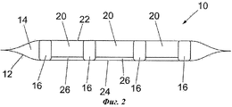
На фиг.2 представлен поперечный разрез по линии A-A раневой повязки по фиг.1.Figure 2 presents a cross section along the line A-A of the wound dressing of figure 1.
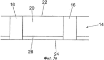
На фиг.3a схематически представлен разрез раневой повязки по фиг.1, показывающий расстояние между двумя стержневидными элементами до удаления воздуха из ячейки.Fig. 3a is a schematic sectional view of the wound dressing of Fig. 1, showing the distance between two rod-shaped elements before air is removed from the cell.
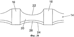
На фиг.3b схематически представлен разрез раневой повязки по фиг.3a после удаления воздуха из ячейки.Fig. 3b is a schematic sectional view of the wound dressing of Fig. 3a after removal of air from the cell.
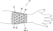
На фиг.4 схематически представлено применение раневой повязки в соответствии с настоящим изобретением, наложенной на руку пациента.Figure 4 schematically shows the use of a wound dressing in accordance with the present invention, applied to the patient's arm.
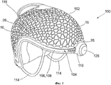
На фиг.5 представлен общий вид раневой повязки в соответствии со вторым вариантом осуществления настоящего изобретения, имеющей вид головной раневой повязки.Figure 5 presents a General view of the wound dressing in accordance with the second embodiment of the present invention, having the form of a head wound dressing.
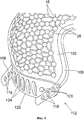
На фиг.6 представлен частичный вид сбоку сзади раневой повязки по фиг.5.FIG. 6 is a partial rear side view of the wound dressing of FIG. 5.
На фиг.1 и 2 представлена раневая повязка 10 в соответствии с первым вариантом осуществления настоящего изобретения. Раневая повязка 10 содержит герметичную оболочку 12, имеющую по меньшей мере одну ячейку 14; множество стержневидных элементов 16, расположенных на расстоянии друг от друга внутри по меньшей мере одной ячейки 14, и средство для удаления воздуха из по меньшей мере одной ячейки (не показано).Figures 1 and 2 show a wound dressing 10 in accordance with a first embodiment of the present invention. The wound dressing 10 comprises an
Герметичная оболочка 12 содержит первый слой 22 пленки и второй слой 24 пленки, герметично соединенные по краям, ограничивая одну или более ячеек в герметичной оболочке 12. Первый и второй слои 22, 24 пленки могут быть дополнительно соединены в разных точках для ограничения одной или более дополнительных ячеек внутри герметичной оболочки 12.The
Первый и второй слои 22, 24 пленки выполнены из материала ПВХ и термосварены друг с другом для получения герметичной оболочки 12 и/или ячейки.The first and
Стержневидные элементы 16 (далее - «столбики») имеют по существу цилиндрическую форму и соединены с соседним элементом с помощью соединительного элемента 26. В этой конструкции столбики 16 и соединительные элементы 26 задают решетчатую структуру. В соответствии с предпочтительным вариантом осуществления настоящего изобретения столбики изготовлены из материала на основе силикона, а соединительные элементы 26 изготовлены из упругого материала, такого как эластичный пластмассовый материал.The rod-shaped elements 16 (hereinafter - the "columns") have a substantially cylindrical shape and are connected to the neighboring element by means of a connecting
Столбики 16 могут удерживаться с возможностью перемещения между первым и вторым слоями 22, 24 или могут удерживаться на месте между слоями 22, 24 пленки путем соединения с первым и/или вторым слоем пленки.
Средство для удаления воздуха из по меньшей мере одной ячейки представляет собой вакуумный выпускной клапан (не показан), содержащий обратный клапан для предотвращения возврата воздуха в по меньшей мере одну ячейку при удалении воздуха из ячейки 14.The means for removing air from at least one cell is a vacuum outlet valve (not shown) comprising a check valve to prevent air from returning to at least one cell when removing air from
На фиг.3a и 3b можно видеть, что при удалении воздуха из ячейки 14 часть первого слоя 22 пленки и часть второго слоя 24 пленки втягиваются в пространство 20 между двумя соседними столбиками 16, как хорошо видно на фиг.3b. Когда слои 22, 24 пленки втягиваются в пространство 20 вакуумом, образовавшимся после удаления воздуха, общая площадь поверхности раневой повязки 10 уменьшается, приводя к уменьшению расстояния между соседними столбиками 16.On figa and 3b it can be seen that when removing air from the
Когда соседние столбики 16 притягиваются друг к другу, соединительные элементы 26 изгибаются вовнутрь в пространство 20.When
Слои 22, 24 пленки обеспечивают контролируемое и самоограничивающееся уменьшение длины раневой повязки 10 по одной или двум осям при удалении воздуха.The
Когда в ячейку 14 снова подают воздух, столбики 16 возвращаются в первоначальное положение благодаря упругости соединительных элементов 26, благодаря которой соединительные элементы 26 распрямляются и, таким образом, толкают столбики 16 друг от друга.When air is again supplied to the
Столбики 16 расположены на расстоянии друг от друга в заданном порядке в соответствии с необходимостью. Таким образом, форма элементов решетки (т.е. столбиков 16 и соединительных элементов 26) и расстояние между ними определяют изменение раневой повязки 10 при приложении вакуума. Например, если столбики 16 расположены в виде последовательности длинных тонких полос, параллельных друг другу, повязка уменьшается по поперечной оси больше, чем по продольной.
Раневая повязка 10 также содержит средство (не показано) для введения воздуха в по меньшей мере одну ячейку, которое может являться ручным насосом или впускным клапаном, выполненным с возможностью соединения с компрессором.The wound dressing 10 also includes means (not shown) for introducing air into at least one cell, which may be a hand pump or an intake valve configured to connect to a compressor.
На фиг.4 представлена раневая повязка в соответствии с первым вариантом осуществления настоящего изобретения, наложенная на руку пациента для уменьшения послеоперационного отека руки пациента.Figure 4 presents a wound dressing in accordance with the first embodiment of the present invention, applied to the patient's arm to reduce postoperative swelling of the patient's arm.
Сначала раневую повязку размещают вокруг послеоперационной раны и фиксируют с помощью соответствующего средства, например ленты, ремня, застежки-липучки VELCRO®, пластыря и т.п. Затем к части тела прикладывают давление, чтобы ограничить отек части тела путем удаления воздуха из по меньшей мере одной ячейки. Как описано выше, вследствие удаления воздуха слои 22, 24 пленки втягиваются в пространство 20 между столбиками 16, что приводит к притягиванию столбиков 16 ближе друг к другу и к уменьшению общих размеров раневой повязки 10.First, a wound dressing is placed around the postoperative wound and fixed using appropriate means, for example, tape, belt, VELCRO ® Velcro, plaster, etc. Then pressure is applied to the body part to limit swelling of the body part by removing air from at least one cell. As described above, due to the removal of air, the
На фиг.5 представлена раневая повязка в соответствии со вторым вариантом осуществления настоящего изобретения. Раневая повязка 100 является головной раневой повязкой и содержит часть 102, покрывающую голову, и обрамляющую часть 104 для закрепления повязки на голове пациента.5 shows a wound dressing in accordance with a second embodiment of the present invention. The wound dressing 100 is a head wound dressing and includes a
Часть 102, покрывающая голову, представляет собой конструкцию, подобную раневой повязке 10, описанной выше, и одинаковые элементы обозначены одинаковыми позициями.The
Обрамляющая часть 104 содержит фиксирующую ленту 106 для фиксации повязки 100 на голове пациента и пару удерживающих элементов 114, расположенных на противоположных сторонах повязки 100 и размещенных таким образом, чтобы при применении находиться по бокам головы пациента.The framing
Элементы обрамляющей части 104 изготовлены из гибкого пластика, что позволяет подогнать их по голове пациента и при этом обеспечивает их достаточную жесткость, не допускающую самопроизвольного спадания раневой повязки 100 с головы.The elements of the framing
Фиксирующая лента 106 выполнена с возможностью прохождения вокруг головы пациента. В соответствии с представленным вариантом осуществления изобретения фиксирующая лента 106 содержит два ленточных элемента 108, каждый из которых выполнен с возможностью прохождения от лба пользователя вдоль виска и вниз, таким образом, что они заканчиваются под затылочной частью, обеспечивая надежное крепление.The fixing tape 106 is configured to extend around the patient’s head. In accordance with the presented embodiment of the invention, the fixing tape 106 contains two
Обрамляющая часть 104 также содержит средство для регулирования рабочей длины фиксирующей ленты 106. В соответствии с представленным вариантом осуществления настоящего изобретения повязка 100 содержит первое средство для регулирования рабочей длины фиксирующей ленты 106, расположенное спереди раневой повязки 100, и второе средство для регулирования рабочей длины фиксирующей ленты 106, расположенное сзади раневой повязки 100.The framing
Переднее регулирующее средство представляет собой храповой механизм 110, соединенный с первым концом двух ленточных элементов 108. Храповой механизм содержит кнопку 126 для регулирования натяжения передней части фиксирующей ленты 106.The front adjusting means is a
Заднее регулирующее средство по фиг.6 представляет собой регулирующую застежку 112 известного типа. Регулирующая застежка 112 содержит множество отверстий 118, расположенных у второго конца каждого из ленточных элементов 108. Отверстия 118 выполнены с возможностью приема соответствующих выступов 120, расположенных на крепежном элементе 122. Количество отверстий 118 и соответствующих выступов 120 определяет количество регулировочных положений, которые можно применять для увеличения натяжения задней части фиксирующей ленты 106. В соответствии с представленным вариантом осуществления каждый из ленточных элементов 108 содержит четыре отверстия 118. Как показано на фиг.6, крепежный элемент 122 может включать множество принимающих петель 124, в которых могут быть надежно вдеты концы ленточных элементов 118.The rear adjusting means of FIG. 6 is an adjusting
Каждый из удерживающих элементов 114 выполнен с возможностью закрепления вокруг уха пользователя. В соответствии с представленным вариантом осуществления первый конец удерживающего элемента 114 соединяется с фиксирующей лентой 106 рядом с передним концом раневой повязки 100, а второй конец соединяется с фиксирующей лентой 106 рядом с задним концом раневой повязки 100.Each of the retaining
Удерживающие элементы 114 ограничивают перемещение головного убора независимо от фиксирующей ленты 106 и совместно с фиксирующей лентой 106 позволяют фиксировать раневую повязку 100 на голове без применения подбородочной тесемки или закрывания ушей.The retaining
Хотя обрамляющая структура раневой повязки 100 описана на частном примере применения с головным убором для уменьшения послеоперационного отека раны головы или контроля кровопотери из ран головы, оригинальная обрамляющая структура, описанная выше, может быть встроена в головной убор при необходимости фиксации головного убора на голове пользователя. Например, обрамляющая конструкция может быть встроена в защитный или предохранительный шлем для создания шлема без подбородочной тесемки.Although the framing structure of the wound dressing 100 is described in a particular application with a headgear to reduce postoperative edema of the head wound or control blood loss from head wounds, the original framing structure described above can be integrated into the headpiece if it is necessary to fix the headgear on the user's head. For example, the framing may be integrated in a protective or safety helmet to create a helmet without a chin strap.
Все признаки, раскрытые в настоящем описании изобретения, включая прилагаемую формулу изобретения, реферат и чертежи, и/или все раскрытые этапы способа или процесса, можно применять в любых комбинациях, за исключением таких, в которых по меньшей мере некоторые из этих признаков и/или этапов являются взаимно исключающими.All features disclosed in the present description of the invention, including the appended claims, abstract and drawings, and / or all the disclosed steps of a method or process, can be used in any combination, except for those in which at least some of these features and / or stages are mutually exclusive.
Каждый из признаков, раскрытых в настоящем описании изобретения включая прилагаемую формулу изобретения, реферат и чертежи, может быть заменен альтернативным признаком, имеющим такое же, эквивалентное или подобное назначение, если не заявлено иначе. Таким образом, если не заявлено иначе, каждый из раскрытых признаков является только примером из группы эквивалентных или подобных признаков.Each of the features disclosed in the present description of the invention, including the appended claims, abstract and drawings, may be replaced by an alternative feature having the same, equivalent or similar purpose, unless stated otherwise. Thus, unless stated otherwise, each of the disclosed features is only an example from a group of equivalent or similar features.
Изобретение не ограничено деталями описанных вариантов осуществления. Изобретение распространяется на любой новый признак или любую новую комбинацию признаков, раскрытых в этом описании, включая прилагаемую формулу изобретения, реферат и чертежи, или на любой новый этап или комбинацию этапов способа или процесса, раскрытых в этом описании.The invention is not limited to the details of the described embodiments. The invention extends to any new feature or any new combination of features disclosed in this description, including the appended claims, abstract and drawings, or to any new step or combination of steps of a method or process disclosed in this description.
Claims (19)
- наложение на часть тела или рану повязки, образованной герметичной оболочкой, имеющей по меньшей мере одну ячейку и множество стержневидных элементов, расположенных на расстоянии друг от друга, и
- приложение давления к части тела или ране путем уменьшения пространства между по меньшей мере одной парой стержневидных элементов посредством удаления воздуха из по меньшей мере одной ячейки.18. A method of reducing postoperative edema of a part of the human or animal body or controlling blood loss from wounds, comprising the following steps:
- applying a bandage to a body part or wound formed by a sealed sheath having at least one cell and a plurality of rod-shaped elements spaced apart from each other, and
- applying pressure to a part of the body or wound by reducing the space between at least one pair of rod-like elements by removing air from at least one cell.
Applications Claiming Priority (3)
| Application Number | Priority Date | Filing Date | Title |
|---|---|---|---|
| GB0811136A GB2461048C (en) | 2008-06-18 | 2008-06-18 | Improved wound dressing |
| GB0811136.1 | 2008-06-18 | ||
| PCT/GB2009/050688 WO2009153594A1 (en) | 2008-06-18 | 2009-06-17 | Wounddressing and headgear |
Publications (2)
| Publication Number | Publication Date |
|---|---|
| RU2010151858A RU2010151858A (en) | 2012-07-27 |
| RU2504355C2 true RU2504355C2 (en) | 2014-01-20 |
Family
ID=39672461
Family Applications (1)
| Application Number | Title | Priority Date | Filing Date |
|---|---|---|---|
| RU2010151858/14A RU2504355C2 (en) | 2008-06-18 | 2009-06-17 | Wound bandage |
Country Status (16)
| Country | Link |
|---|---|
| US (1) | US8481804B2 (en) |
| EP (1) | EP2293749B1 (en) |
| JP (1) | JP5462249B2 (en) |
| KR (1) | KR101459745B1 (en) |
| CN (1) | CN102083398B (en) |
| AU (1) | AU2009261685B2 (en) |
| BR (1) | BRPI0914844A2 (en) |
| CA (1) | CA2728157C (en) |
| ES (1) | ES2602115T3 (en) |
| GB (1) | GB2461048C (en) |
| IL (1) | IL210050A (en) |
| MX (1) | MX2010013982A (en) |
| MY (1) | MY159462A (en) |
| RU (1) | RU2504355C2 (en) |
| WO (1) | WO2009153594A1 (en) |
| ZA (1) | ZA201100372B (en) |
Families Citing this family (55)
| Publication number | Priority date | Publication date | Assignee | Title |
|---|---|---|---|---|
| HUE043133T2 (en) | 2007-11-21 | 2019-07-29 | Smith & Nephew | Wound dressing |
| CA2705896C (en) | 2007-11-21 | 2019-01-08 | Smith & Nephew Plc | Wound dressing |
| GB0804654D0 (en) | 2008-03-13 | 2008-04-16 | Smith & Nephew | Vacuum closure device |
| US9421132B2 (en) | 2011-02-04 | 2016-08-23 | University Of Massachusetts | Negative pressure wound closure device |
| CN106974683B (en) | 2011-02-04 | 2020-02-21 | 马萨诸塞州大学 | Negative pressure wound closure device |
| CN107252383A (en) | 2011-07-14 | 2017-10-17 | 史密夫及内修公开有限公司 | Wound dressing and treatment method |
| WO2013136181A2 (en) | 2012-03-12 | 2013-09-19 | Smith & Nephew Plc | Reduced pressure apparatus and methods |
| WO2013175310A2 (en) | 2012-05-22 | 2013-11-28 | Smith & Nephew Plc | Apparatuses and methods for wound therapy |
| CA2874396A1 (en) | 2012-05-22 | 2014-01-23 | Smith & Nephew Plc | Wound closure device |
| CA2874581C (en) | 2012-05-24 | 2022-06-07 | Smith & Nephew Inc. | Devices and methods for treating and closing wounds with negative pressure |
| AU2013290346B2 (en) | 2012-07-16 | 2018-06-07 | Smith & Nephew, Inc. | Negative pressure wound closure device |
| WO2014024792A1 (en) * | 2012-08-07 | 2014-02-13 | 株式会社瑞光 | Disposable wearing article |
| EP2968016B1 (en) | 2013-03-13 | 2018-07-11 | Smith&Nephew, Inc. | Negative pressure wound closure device and systems and methods of use in treating wounds with negative pressure |
| US10159771B2 (en) | 2013-03-14 | 2018-12-25 | Smith & Nephew Plc | Compressible wound fillers and systems and methods of use in treating wounds with negative pressure |
| AU2014291873B2 (en) | 2013-07-16 | 2019-01-24 | Smith & Nephew Plc | Apparatus for wound therapy |
| JP6723917B2 (en) | 2013-10-21 | 2020-07-15 | スミス アンド ネフュー インコーポレイテッド | Negative pressure wound closure device |
| JP6742908B2 (en) | 2014-01-21 | 2020-08-19 | スミス アンド ネフュー ピーエルシーSmith & Nephew Public Limited Company | Crushable negative pressure wound dressing |
| US10179073B2 (en) | 2014-01-21 | 2019-01-15 | Smith & Nephew Plc | Wound treatment apparatuses |
| US9867965B1 (en) | 2014-04-25 | 2018-01-16 | Byo Health, L.L.C. | Medical bandage for the head, a limb or a stump |
| GB2525658B (en) * | 2014-05-01 | 2016-05-18 | Timothy Jake | Improved wound dressing |
| GB2529699A (en) * | 2014-08-29 | 2016-03-02 | Airhead Design Ltd | Inflatable helmet |
| GB2536264B (en) * | 2015-03-11 | 2017-11-08 | Timothy Jake | Graduated pressure applicator |
| CN113367890B (en) | 2015-04-27 | 2023-02-21 | 史密夫及内修公开有限公司 | Pressure reducing device |
| EP3288509B1 (en) | 2015-04-29 | 2022-06-29 | Smith & Nephew, Inc | Negative pressure wound closure device |
| US11471586B2 (en) | 2015-12-15 | 2022-10-18 | University Of Massachusetts | Negative pressure wound closure devices and methods |
| US10814049B2 (en) | 2015-12-15 | 2020-10-27 | University Of Massachusetts | Negative pressure wound closure devices and methods |
| US10575991B2 (en) | 2015-12-15 | 2020-03-03 | University Of Massachusetts | Negative pressure wound closure devices and methods |
| AU2017230775B2 (en) | 2016-03-07 | 2021-12-23 | Smith & Nephew Plc | Wound treatment apparatuses and methods with negative pressure source integrated into wound dressing |
| AU2017256692B2 (en) | 2016-04-26 | 2022-03-03 | Smith & Nephew Plc | Wound dressings and methods of use with integrated negative pressure source having a fluid ingress inhibition component |
| AU2017259003B2 (en) | 2016-05-03 | 2022-09-22 | Smith & Nephew Plc | Systems and methods for driving negative pressure sources in negative pressure therapy systems |
| WO2017191149A1 (en) | 2016-05-03 | 2017-11-09 | Smith & Nephew Plc | Optimizing power transfer to negative pressure sources in negative pressure therapy systems |
| WO2017191154A1 (en) | 2016-05-03 | 2017-11-09 | Smith & Nephew Plc | Negative pressure wound therapy device activation and control |
| CN109561994B (en) | 2016-08-25 | 2022-03-15 | 史密夫及内修公开有限公司 | Absorbent negative pressure wound therapy dressing |
| US11135351B2 (en) | 2016-08-30 | 2021-10-05 | Smith & Nephew Plc | Systems and methods for applying reduced pressure therapy |
| EP3518847B1 (en) | 2016-09-27 | 2023-03-01 | Smith & Nephew plc | Wound closure devices with dissolvable portions |
| US11564847B2 (en) | 2016-09-30 | 2023-01-31 | Smith & Nephew Plc | Negative pressure wound treatment apparatuses and methods with integrated electronics |
| GB2555584B (en) * | 2016-10-28 | 2020-05-27 | Smith & Nephew | Multi-layered wound dressing and method of manufacture |
| WO2018085457A1 (en) | 2016-11-02 | 2018-05-11 | Smith & Nephew Inc. | Wound closure devices |
| JP7361606B2 (en) | 2017-03-08 | 2023-10-16 | スミス アンド ネフュー ピーエルシー | Control of negative pressure wound therapy devices in the presence of fault conditions |
| JP7121050B2 (en) | 2017-05-09 | 2022-08-17 | スミス アンド ネフュー ピーエルシー | Redundant control of negative pressure wound therapy systems |
| AU2018285236B2 (en) | 2017-06-13 | 2024-02-29 | Smith & Nephew Plc | Wound closure device and method of use |
| US11324876B2 (en) | 2017-06-13 | 2022-05-10 | Smith & Nephew Plc | Collapsible structure and method of use |
| JP2020523052A (en) | 2017-06-14 | 2020-08-06 | スミス アンド ネフュー インコーポレイテッド | Fluid removal management and control of wound closure in wound care |
| EP3638173A1 (en) | 2017-06-14 | 2020-04-22 | Smith & Nephew, Inc | Control of wound closure and fluid removal management in wound therapy |
| US11583623B2 (en) | 2017-06-14 | 2023-02-21 | Smith & Nephew Plc | Collapsible structure for wound closure and method of use |
| JP7419072B2 (en) | 2017-06-14 | 2024-01-22 | スミス アンド ネフュー ピーエルシー | Foldable sheet for wound closure and method of use |
| EP3658090B1 (en) | 2017-07-27 | 2021-11-10 | Smith & Nephew PLC | Customizable wound closure device |
| EP3664756B1 (en) | 2017-08-07 | 2024-01-24 | Smith & Nephew plc | Wound closure device with protective layer |
| WO2019042790A1 (en) | 2017-08-29 | 2019-03-07 | Smith & Nephew Plc | Systems and methods for monitoring wound closure |
| GB201718070D0 (en) | 2017-11-01 | 2017-12-13 | Smith & Nephew | Negative pressure wound treatment apparatuses and methods with integrated electronics |
| AU2018331954A1 (en) | 2017-09-13 | 2020-03-19 | Smith & Nephew Plc | Negative pressure wound treatment apparatuses and methods with integrated electronics |
| GB201718072D0 (en) | 2017-11-01 | 2017-12-13 | Smith & Nephew | Negative pressure wound treatment apparatuses and methods with integrated electronics |
| GB201718054D0 (en) | 2017-11-01 | 2017-12-13 | Smith & Nephew | Sterilization of integrated negative pressure wound treatment apparatuses and sterilization methods |
| US11497653B2 (en) | 2017-11-01 | 2022-11-15 | Smith & Nephew Plc | Negative pressure wound treatment apparatuses and methods with integrated electronics |
| USD898925S1 (en) | 2018-09-13 | 2020-10-13 | Smith & Nephew Plc | Medical dressing |
Citations (5)
| Publication number | Priority date | Publication date | Assignee | Title |
|---|---|---|---|---|
| US5267365A (en) * | 1989-09-19 | 1993-12-07 | Walter Bruno H | Bed mattress or the like and pressurized liquid supply system |
| RU92013711A (en) * | 1992-12-17 | 1995-05-20 | MEDICAL BANDING | |
| WO2005097022A1 (en) * | 2004-04-05 | 2005-10-20 | Jake Timothy | Head dressing |
| US20060174895A1 (en) * | 2005-02-04 | 2006-08-10 | Sdgi Holdings | Adjustable orthopedic positioning device and method of use |
| GB2435833A (en) * | 2006-03-06 | 2007-09-12 | Jake Timothy | Vacuum Head dressing |
Family Cites Families (7)
| Publication number | Priority date | Publication date | Assignee | Title |
|---|---|---|---|---|
| US5014365A (en) * | 1989-01-23 | 1991-05-14 | Maxpro Helmets, Inc. | Gas-fitted protective helmet |
| US5168576A (en) * | 1990-10-03 | 1992-12-08 | Krent Edward D | Body protective device |
| JP3665879B2 (en) * | 1995-05-13 | 2005-06-29 | 克治 武藤 | Vacuum solid plate by combination of special shape net |
| US5752298A (en) * | 1996-10-15 | 1998-05-19 | Down East, Inc. | Earcup tension adjustment strap assembly |
| US6656143B2 (en) * | 2001-03-01 | 2003-12-02 | Samuel Robert Browd | Vacuum fixation bag for stabilizing the head |
| US20030212357A1 (en) * | 2002-05-10 | 2003-11-13 | Pace Edgar Alan | Method and apparatus for treating wounds with oxygen and reduced pressure |
| US7094212B2 (en) * | 2002-10-11 | 2006-08-22 | Ossur Hf | Rigid dressing |
-
2008
- 2008-06-18 GB GB0811136A patent/GB2461048C/en not_active Expired - Fee Related
-
2009
- 2009-06-17 ES ES09766155.7T patent/ES2602115T3/en active Active
- 2009-06-17 CA CA2728157A patent/CA2728157C/en active Active
- 2009-06-17 JP JP2011514130A patent/JP5462249B2/en not_active Expired - Fee Related
- 2009-06-17 BR BRPI0914844A patent/BRPI0914844A2/en not_active Application Discontinuation
- 2009-06-17 MY MYPI2010006090A patent/MY159462A/en unknown
- 2009-06-17 US US12/999,181 patent/US8481804B2/en active Active
- 2009-06-17 AU AU2009261685A patent/AU2009261685B2/en active Active
- 2009-06-17 MX MX2010013982A patent/MX2010013982A/en active IP Right Grant
- 2009-06-17 EP EP09766155.7A patent/EP2293749B1/en active Active
- 2009-06-17 KR KR1020107029522A patent/KR101459745B1/en active IP Right Grant
- 2009-06-17 RU RU2010151858/14A patent/RU2504355C2/en active
- 2009-06-17 WO PCT/GB2009/050688 patent/WO2009153594A1/en active Application Filing
- 2009-06-17 CN CN200980123223.4A patent/CN102083398B/en active Active
-
2010
- 2010-12-16 IL IL210050A patent/IL210050A/en active IP Right Grant
-
2011
- 2011-01-14 ZA ZA2011/00372A patent/ZA201100372B/en unknown
Patent Citations (5)
| Publication number | Priority date | Publication date | Assignee | Title |
|---|---|---|---|---|
| US5267365A (en) * | 1989-09-19 | 1993-12-07 | Walter Bruno H | Bed mattress or the like and pressurized liquid supply system |
| RU92013711A (en) * | 1992-12-17 | 1995-05-20 | MEDICAL BANDING | |
| WO2005097022A1 (en) * | 2004-04-05 | 2005-10-20 | Jake Timothy | Head dressing |
| US20060174895A1 (en) * | 2005-02-04 | 2006-08-10 | Sdgi Holdings | Adjustable orthopedic positioning device and method of use |
| GB2435833A (en) * | 2006-03-06 | 2007-09-12 | Jake Timothy | Vacuum Head dressing |
Also Published As
| Publication number | Publication date |
|---|---|
| KR101459745B1 (en) | 2014-11-12 |
| GB2461048A (en) | 2009-12-23 |
| KR20110042270A (en) | 2011-04-26 |
| EP2293749A1 (en) | 2011-03-16 |
| CN102083398B (en) | 2014-10-01 |
| RU2010151858A (en) | 2012-07-27 |
| CA2728157C (en) | 2015-11-10 |
| CA2728157A1 (en) | 2009-12-23 |
| GB0811136D0 (en) | 2008-07-23 |
| AU2009261685B2 (en) | 2013-05-30 |
| US8481804B2 (en) | 2013-07-09 |
| JP2011524768A (en) | 2011-09-08 |
| MY159462A (en) | 2017-01-13 |
| BRPI0914844A2 (en) | 2020-01-28 |
| IL210050A (en) | 2015-09-24 |
| US20110144555A1 (en) | 2011-06-16 |
| WO2009153594A1 (en) | 2009-12-23 |
| ZA201100372B (en) | 2011-10-26 |
| GB2461048B (en) | 2012-07-11 |
| AU2009261685A1 (en) | 2009-12-23 |
| GB2461048C (en) | 2012-11-21 |
| IL210050A0 (en) | 2011-02-28 |
| ES2602115T3 (en) | 2017-02-17 |
| JP5462249B2 (en) | 2014-04-02 |
| MX2010013982A (en) | 2011-05-23 |
| CN102083398A (en) | 2011-06-01 |
| EP2293749B1 (en) | 2016-08-10 |
Similar Documents
| Publication | Publication Date | Title |
|---|---|---|
| RU2504355C2 (en) | Wound bandage | |
| US20220313893A1 (en) | Collapsible dressing for negative pressure wound treatment | |
| US4592357A (en) | Septal splint | |
| ES2348958T3 (en) | DEVICE FOR THE TREATMENT OF WOUNDS APPLYING A PARTIAL VACUUM. | |
| CN105412998B (en) | Method and device for applying negative pressure wound therapy to a closed incision | |
| ES2817834T3 (en) | System that uses vacuum to promote the healing of sprains | |
| US9867965B1 (en) | Medical bandage for the head, a limb or a stump | |
| BRMU9002456Y1 (en) | HEMOSTATIC DEVICE | |
| BRMU9100069U2 (en) | hemostatic device | |
| CN209203649U (en) | A kind of department of general surgery's edge of a knife recovery care device | |
| WO2006136024A1 (en) | Cast venting devices made of two flexible layers | |
| JP3114350U (en) | Nasal fixture | |
| CN215458370U (en) | Hemostatic wrist strap | |
| CN211863061U (en) | Neck support for fixing neck | |
| CN214858233U (en) | Local pressurization bandage | |
| CN216021565U (en) | Neck fixing protective plate for thyroid gland after operation | |
| CN209884519U (en) | Wound protection device for thoracic surgery | |
| CN220404261U (en) | Craniomaxillofacial wound bandaging hemostatic towel | |
| GB2525658A (en) | Improved wound dressing | |
| GB2319963A (en) | An anatomical restraint |