KR20210149697A - Systems and methods for managing power - Google Patents
Systems and methods for managing power Download PDFInfo
- Publication number
- KR20210149697A KR20210149697A KR1020217029050A KR20217029050A KR20210149697A KR 20210149697 A KR20210149697 A KR 20210149697A KR 1020217029050 A KR1020217029050 A KR 1020217029050A KR 20217029050 A KR20217029050 A KR 20217029050A KR 20210149697 A KR20210149697 A KR 20210149697A
- Authority
- KR
- South Korea
- Prior art keywords
- power
- converter
- bus
- inverter
- power source
- Prior art date
Links
Images


Classifications
-
- H—ELECTRICITY
- H02—GENERATION; CONVERSION OR DISTRIBUTION OF ELECTRIC POWER
- H02J—CIRCUIT ARRANGEMENTS OR SYSTEMS FOR SUPPLYING OR DISTRIBUTING ELECTRIC POWER; SYSTEMS FOR STORING ELECTRIC ENERGY
- H02J3/00—Circuit arrangements for ac mains or ac distribution networks
- H02J3/28—Arrangements for balancing of the load in a network by storage of energy
-
- H—ELECTRICITY
- H02—GENERATION; CONVERSION OR DISTRIBUTION OF ELECTRIC POWER
- H02J—CIRCUIT ARRANGEMENTS OR SYSTEMS FOR SUPPLYING OR DISTRIBUTING ELECTRIC POWER; SYSTEMS FOR STORING ELECTRIC ENERGY
- H02J1/00—Circuit arrangements for dc mains or dc distribution networks
- H02J1/10—Parallel operation of dc sources
- H02J1/102—Parallel operation of dc sources being switching converters
-
- H—ELECTRICITY
- H02—GENERATION; CONVERSION OR DISTRIBUTION OF ELECTRIC POWER
- H02J—CIRCUIT ARRANGEMENTS OR SYSTEMS FOR SUPPLYING OR DISTRIBUTING ELECTRIC POWER; SYSTEMS FOR STORING ELECTRIC ENERGY
- H02J1/00—Circuit arrangements for dc mains or dc distribution networks
- H02J1/002—Intermediate AC, e.g. DC supply with intermediated AC distribution
-
- H—ELECTRICITY
- H02—GENERATION; CONVERSION OR DISTRIBUTION OF ELECTRIC POWER
- H02J—CIRCUIT ARRANGEMENTS OR SYSTEMS FOR SUPPLYING OR DISTRIBUTING ELECTRIC POWER; SYSTEMS FOR STORING ELECTRIC ENERGY
- H02J1/00—Circuit arrangements for dc mains or dc distribution networks
- H02J1/10—Parallel operation of dc sources
- H02J1/108—Parallel operation of dc sources using diodes blocking reverse current flow
-
- H—ELECTRICITY
- H02—GENERATION; CONVERSION OR DISTRIBUTION OF ELECTRIC POWER
- H02J—CIRCUIT ARRANGEMENTS OR SYSTEMS FOR SUPPLYING OR DISTRIBUTING ELECTRIC POWER; SYSTEMS FOR STORING ELECTRIC ENERGY
- H02J1/00—Circuit arrangements for dc mains or dc distribution networks
- H02J1/10—Parallel operation of dc sources
- H02J1/12—Parallel operation of dc generators with converters, e.g. with mercury-arc rectifier
-
- H—ELECTRICITY
- H02—GENERATION; CONVERSION OR DISTRIBUTION OF ELECTRIC POWER
- H02J—CIRCUIT ARRANGEMENTS OR SYSTEMS FOR SUPPLYING OR DISTRIBUTING ELECTRIC POWER; SYSTEMS FOR STORING ELECTRIC ENERGY
- H02J3/00—Circuit arrangements for ac mains or ac distribution networks
- H02J3/18—Arrangements for adjusting, eliminating or compensating reactive power in networks
- H02J3/1821—Arrangements for adjusting, eliminating or compensating reactive power in networks using shunt compensators
- H02J3/1835—Arrangements for adjusting, eliminating or compensating reactive power in networks using shunt compensators with stepless control
-
- H—ELECTRICITY
- H02—GENERATION; CONVERSION OR DISTRIBUTION OF ELECTRIC POWER
- H02J—CIRCUIT ARRANGEMENTS OR SYSTEMS FOR SUPPLYING OR DISTRIBUTING ELECTRIC POWER; SYSTEMS FOR STORING ELECTRIC ENERGY
- H02J3/00—Circuit arrangements for ac mains or ac distribution networks
- H02J3/28—Arrangements for balancing of the load in a network by storage of energy
- H02J3/32—Arrangements for balancing of the load in a network by storage of energy using batteries with converting means
-
- H—ELECTRICITY
- H02—GENERATION; CONVERSION OR DISTRIBUTION OF ELECTRIC POWER
- H02J—CIRCUIT ARRANGEMENTS OR SYSTEMS FOR SUPPLYING OR DISTRIBUTING ELECTRIC POWER; SYSTEMS FOR STORING ELECTRIC ENERGY
- H02J3/00—Circuit arrangements for ac mains or ac distribution networks
- H02J3/38—Arrangements for parallely feeding a single network by two or more generators, converters or transformers
- H02J3/381—Dispersed generators
-
- H—ELECTRICITY
- H02—GENERATION; CONVERSION OR DISTRIBUTION OF ELECTRIC POWER
- H02J—CIRCUIT ARRANGEMENTS OR SYSTEMS FOR SUPPLYING OR DISTRIBUTING ELECTRIC POWER; SYSTEMS FOR STORING ELECTRIC ENERGY
- H02J3/00—Circuit arrangements for ac mains or ac distribution networks
- H02J3/38—Arrangements for parallely feeding a single network by two or more generators, converters or transformers
- H02J3/40—Synchronising a generator for connection to a network or to another generator
-
- H—ELECTRICITY
- H02—GENERATION; CONVERSION OR DISTRIBUTION OF ELECTRIC POWER
- H02J—CIRCUIT ARRANGEMENTS OR SYSTEMS FOR SUPPLYING OR DISTRIBUTING ELECTRIC POWER; SYSTEMS FOR STORING ELECTRIC ENERGY
- H02J7/00—Circuit arrangements for charging or depolarising batteries or for supplying loads from batteries
- H02J7/34—Parallel operation in networks using both storage and other dc sources, e.g. providing buffering
- H02J7/35—Parallel operation in networks using both storage and other dc sources, e.g. providing buffering with light sensitive cells
-
- H—ELECTRICITY
- H02—GENERATION; CONVERSION OR DISTRIBUTION OF ELECTRIC POWER
- H02J—CIRCUIT ARRANGEMENTS OR SYSTEMS FOR SUPPLYING OR DISTRIBUTING ELECTRIC POWER; SYSTEMS FOR STORING ELECTRIC ENERGY
- H02J9/00—Circuit arrangements for emergency or stand-by power supply, e.g. for emergency lighting
- H02J9/04—Circuit arrangements for emergency or stand-by power supply, e.g. for emergency lighting in which the distribution system is disconnected from the normal source and connected to a standby source
- H02J9/06—Circuit arrangements for emergency or stand-by power supply, e.g. for emergency lighting in which the distribution system is disconnected from the normal source and connected to a standby source with automatic change-over, e.g. UPS systems
- H02J9/062—Circuit arrangements for emergency or stand-by power supply, e.g. for emergency lighting in which the distribution system is disconnected from the normal source and connected to a standby source with automatic change-over, e.g. UPS systems for AC powered loads
-
- H—ELECTRICITY
- H02—GENERATION; CONVERSION OR DISTRIBUTION OF ELECTRIC POWER
- H02J—CIRCUIT ARRANGEMENTS OR SYSTEMS FOR SUPPLYING OR DISTRIBUTING ELECTRIC POWER; SYSTEMS FOR STORING ELECTRIC ENERGY
- H02J2300/00—Systems for supplying or distributing electric power characterised by decentralized, dispersed, or local generation
- H02J2300/20—The dispersed energy generation being of renewable origin
- H02J2300/22—The renewable source being solar energy
- H02J2300/24—The renewable source being solar energy of photovoltaic origin
- H02J2300/26—The renewable source being solar energy of photovoltaic origin involving maximum power point tracking control for photovoltaic sources
-
- H—ELECTRICITY
- H02—GENERATION; CONVERSION OR DISTRIBUTION OF ELECTRIC POWER
- H02J—CIRCUIT ARRANGEMENTS OR SYSTEMS FOR SUPPLYING OR DISTRIBUTING ELECTRIC POWER; SYSTEMS FOR STORING ELECTRIC ENERGY
- H02J7/00—Circuit arrangements for charging or depolarising batteries or for supplying loads from batteries
- H02J7/0047—Circuit arrangements for charging or depolarising batteries or for supplying loads from batteries with monitoring or indicating devices or circuits
- H02J7/0048—Detection of remaining charge capacity or state of charge [SOC]
-
- H—ELECTRICITY
- H02—GENERATION; CONVERSION OR DISTRIBUTION OF ELECTRIC POWER
- H02J—CIRCUIT ARRANGEMENTS OR SYSTEMS FOR SUPPLYING OR DISTRIBUTING ELECTRIC POWER; SYSTEMS FOR STORING ELECTRIC ENERGY
- H02J7/00—Circuit arrangements for charging or depolarising batteries or for supplying loads from batteries
- H02J7/0047—Circuit arrangements for charging or depolarising batteries or for supplying loads from batteries with monitoring or indicating devices or circuits
- H02J7/005—Detection of state of health [SOH]
-
- Y—GENERAL TAGGING OF NEW TECHNOLOGICAL DEVELOPMENTS; GENERAL TAGGING OF CROSS-SECTIONAL TECHNOLOGIES SPANNING OVER SEVERAL SECTIONS OF THE IPC; TECHNICAL SUBJECTS COVERED BY FORMER USPC CROSS-REFERENCE ART COLLECTIONS [XRACs] AND DIGESTS
- Y02—TECHNOLOGIES OR APPLICATIONS FOR MITIGATION OR ADAPTATION AGAINST CLIMATE CHANGE
- Y02B—CLIMATE CHANGE MITIGATION TECHNOLOGIES RELATED TO BUILDINGS, e.g. HOUSING, HOUSE APPLIANCES OR RELATED END-USER APPLICATIONS
- Y02B10/00—Integration of renewable energy sources in buildings
- Y02B10/70—Hybrid systems, e.g. uninterruptible or back-up power supplies integrating renewable energies
-
- Y—GENERAL TAGGING OF NEW TECHNOLOGICAL DEVELOPMENTS; GENERAL TAGGING OF CROSS-SECTIONAL TECHNOLOGIES SPANNING OVER SEVERAL SECTIONS OF THE IPC; TECHNICAL SUBJECTS COVERED BY FORMER USPC CROSS-REFERENCE ART COLLECTIONS [XRACs] AND DIGESTS
- Y02—TECHNOLOGIES OR APPLICATIONS FOR MITIGATION OR ADAPTATION AGAINST CLIMATE CHANGE
- Y02E—REDUCTION OF GREENHOUSE GAS [GHG] EMISSIONS, RELATED TO ENERGY GENERATION, TRANSMISSION OR DISTRIBUTION
- Y02E10/00—Energy generation through renewable energy sources
- Y02E10/50—Photovoltaic [PV] energy
- Y02E10/56—Power conversion systems, e.g. maximum power point trackers
-
- Y—GENERAL TAGGING OF NEW TECHNOLOGICAL DEVELOPMENTS; GENERAL TAGGING OF CROSS-SECTIONAL TECHNOLOGIES SPANNING OVER SEVERAL SECTIONS OF THE IPC; TECHNICAL SUBJECTS COVERED BY FORMER USPC CROSS-REFERENCE ART COLLECTIONS [XRACs] AND DIGESTS
- Y02—TECHNOLOGIES OR APPLICATIONS FOR MITIGATION OR ADAPTATION AGAINST CLIMATE CHANGE
- Y02E—REDUCTION OF GREENHOUSE GAS [GHG] EMISSIONS, RELATED TO ENERGY GENERATION, TRANSMISSION OR DISTRIBUTION
- Y02E40/00—Technologies for an efficient electrical power generation, transmission or distribution
- Y02E40/30—Reactive power compensation
Abstract
본 발명은 전력 분배 네트워크에서 전력을 관리하기 위한 시스템을 제공한다. 상기 시스템은 각각 복수의 DC(direct current) 전원 중 하나의 출력과 DC 버스 사이에 전기적으로 연결되고, 상기 DC 버스에 전기적으로 병렬로 연결되고, 및 상기 DC 전원으로부터 상기 DC 버스로 전력을 전달하도록 설정되는 복수의 DC/DC 컨버터; 상기 DC 버스에 전기적으로 연결된 적어도 하나의 DC 에너지 저장 장치; 상기 DC 버스에 전기적으로 연결된 입력 및 AC(alternating current) 부하 및 AC 전원 중 적어도 하나에 전기적으로 연결된 출력을 갖는 적어도 하나의 DC/AC 인버터; 및 상기 DC/DC 컨버터를 선택적으로 제어하여 상기 적어도 하나의 에너지 저장 장치로의 전력 전달을 선택적으로 제어하는 하나 이상의 전자 처리(processing) 장치를 포함한다.The present invention provides a system for managing power in a power distribution network. wherein the system is electrically coupled between the output of each of a plurality of direct current (DC) power supplies and a DC bus, electrically coupled to the DC bus in parallel, and configured to transfer power from the DC power source to the DC bus; a plurality of DC/DC converters to be set; at least one DC energy storage device electrically coupled to the DC bus; at least one DC/AC inverter having an input electrically coupled to the DC bus and an output electrically coupled to at least one of an alternating current (AC) load and an AC power source; and one or more electronic processing devices that selectively control the DC/DC converter to selectively control power delivery to the at least one energy storage device.
Description
본 발명은 배전 네트워크에서 전력을 관리하기 위한 시스템에 관한 것이다. 특정한 형태에서, 비록 이에 제한되지는 않지만, 본 발명은 전기 공급 그리드와 통합되고(integrated) 에너지 저장 장치를 포함하는 태양광 발전(photovoltaic; PV) 발전을 포함하는 시스템에 관한 것이다.The present invention relates to a system for managing power in a distribution network. In a particular form, although not limited thereto, the present invention relates to a system comprising photovoltaic (PV) power generation that is integrated with an electricity supply grid and includes an energy storage device.
본 명세서의 다른 이전 간행물 (또는 그로부터 파생된 정보), 또는 알려진 다른 매체에 대한 참조는, 상기 이전 간행물 또는 상기 알려진 다른 매체가 본 명세서와 관련된 노력 분야에서 일반적인 일반 지식의 일부를 형성하는 것에 대한 인정이나 승인, 또는 어떤 형태의 제안으로 받아들여져서도 안 된다.References herein to other prior publications (or information derived therefrom), or other known media, are an admission that they form part of the general general knowledge in the field of endeavor related to this specification. It should not be accepted as an endorsement, approval, or offer of any kind.
주거용, 상업용 및 산업용 전력 이용자의 태양광 발전 이용 붐은 주로 병입 관세 및 기타 보조금을 포함한 재정적 인센티브에 의해 주도되었다. 이러한 인센티브가 지난 몇 년 동안 점차 줄어들면서, 주문(mantra)은 생산된 전력의 '자체 소비'로 옮겨졌다. 태양광 PV 시스템은 일반적으로 부하가 일반적으로 낮은 낮에 최대 전력을 생산하므로, 초과 에너지는 전력 공급 그리드로 내보내지며, 이용자가 부하에 전력을 공급하는 데 소비되지 않는다. 태양광 시스템이 작동하지 않고 일반적으로 부하가 가장 높은 야간 시간에는 부하가 그리드에서 전력을 끌어오고, 이용자는 그리드 운영자가 생성한 전기 요금을 지불해야 한다.The boom in solar power usage by residential, commercial and industrial electricity users has been driven primarily by financial incentives, including feed-in tariffs and other subsidies. As these incentives have dwindled over the past few years, the mantra has shifted to 'self-consumption' of the electricity produced. Solar PV systems typically produce maximum power during the day when the load is usually low, so the excess energy is sent to the power supply grid and is not consumed by users to power the load. During the nighttime hours when the solar system is not working and the load is usually at its highest, the load draws power from the grid, and users have to pay for electricity generated by the grid operator.
따라서, 태양광 PV 시스템에 의해 생성된 초과 전력이, 태양광 PV 시스템이 비활성 상태인 경우 사용을 위해 에너지 저장 장치에 의해 저장될 수 있도록 시스템에 에너지 저장 장치가 포함되는 것이 바람직하다. 에너지 저장 장치, 특히 중요한 에너지 저장 장치를 그리드 연결 태양광 PV 시스템에 통합하는 것은 성능, 효율성 및 비용 속성을 고려해야 하기 때문에 간단한 작업이 아니다.Accordingly, it is desirable to include an energy storage device in the system so that the excess power generated by the solar PV system can be stored by the energy storage device for use when the solar PV system is inactive. Integrating energy storage devices, especially important energy storage devices, into grid-connected solar PV systems is not a straightforward task as performance, efficiency and cost attributes must be considered.
예를 들어, 에너지 저장 장치를 통합하는 시스템은, 일반적으로 부하 또는 그리드에 공급하기 전의 태양광 모듈 및 저장 장치 사이의 수많은 에너지 변환 단계로 인한 비효율성에 어려움을 겪는다. 또한, 에너지 저장 시스템은 이전까지 일반적으로 효율을 감소시키는 저주파 변압기를 요구하는 저장 매체로서, 저전압 배터리를 사용했다.For example, systems incorporating energy storage devices typically suffer from inefficiencies due to numerous energy conversion steps between solar modules and storage devices prior to supplying to a load or grid. In addition, energy storage systems have previously used low-voltage batteries as a storage medium, which typically required low-frequency transformers to reduce efficiency.
따라서, 그리드 연결 태양광 PV 시스템에 에너지 저장을 통합하는 전력 분배 네트워크에서, 효율적인 방식으로 전력을 관리할 수 있는 시스템을 제공하는 것은 유리할 것이다.Therefore, in a power distribution network that integrates energy storage into a grid-connected solar PV system, it would be advantageous to provide a system capable of managing power in an efficient manner.
하나의 넓은 형태에서, 본 발명의 양태는 전력 분배 네트워크에서 전력을 관리하기 위한 시스템을 제공하고자 하며, 상기 시스템은 각각 복수의 DC(direct current) 전원 중 하나의 출력과 DC 버스 사이에 전기적으로 연결되고, 상기 DC 버스에 전기적으로 병렬로 연결되고, 및 상기 DC 전원으로부터 상기 DC 버스로 전력을 전달하도록 설정되는 복수의 DC/DC 컨버터; 상기 DC 버스에 전기적으로 연결된 적어도 하나의 DC 에너지 저장 장치; 상기 DC 버스에 전기적으로 연결된 입력 및 AC(alternating current) 부하 및 AC 전원 중 적어도 하나에 전기적으로 연결된 출력을 갖는 적어도 하나의 DC/AC 인버터; 및 상기 DC/DC 컨버터를 선택적으로 제어하여 상기 적어도 하나의 에너지 저장 장치로의 전력 전달을 선택적으로 제어하는 하나 이상의 전자 처리(processing) 장치를 포함한다.In one broad form, aspects of the present invention seek to provide a system for managing power in a power distribution network, wherein the system is electrically coupled between a DC bus and the output of each of a plurality of direct current (DC) power sources. a plurality of DC/DC converters configured to be electrically coupled to the DC bus in parallel and configured to transfer power from the DC power source to the DC bus; at least one DC energy storage device electrically coupled to the DC bus; at least one DC/AC inverter having an input electrically coupled to the DC bus and an output electrically coupled to at least one of an alternating current (AC) load and an AC power source; and one or more electronic processing devices that selectively control the DC/DC converter to selectively control power delivery to the at least one energy storage device.
일 실시 예에서, 상기 하나 이상의 전자 처리 장치는 컨버터 출력 전압 및 DC 버스 전압 중 적어도 하나에 따라 각 DC/DC 컨버터의 출력을 독립적으로 제어한다. In one embodiment, the one or more electronic processing devices independently control the output of each DC/DC converter according to at least one of a converter output voltage and a DC bus voltage.
일 실시 예에서, 상기 각 DC/DC 컨버터의 출력 전압은 각 컨버터의 개별 입력 전압보다 크다. In one embodiment, the output voltage of each DC/DC converter is greater than the respective input voltage of each converter.
일 실시 예에서, 상기 각 DC/DC 컨버터의 출력 제어는 상기 적어도 하나의 에너지 저장 장치의 충전 한계; 상기 적어도 하나의 에너지 저장 장치의 방전 한계; 상기 적어도 하나의 에너지 저장 장치의 충전 상태(state of charge; SOC); 및 상기 적어도 하나의 에너지 저장 장치의 건강 상태(state of health; SOH) 중 하나 이상에 따라 달라진다.In an embodiment, the output control of each DC/DC converter may include: a charging limit of the at least one energy storage device; a discharge limit of the at least one energy storage device; a state of charge (SOC) of the at least one energy storage device; and a state of health (SOH) of the at least one energy storage device.
일 실시 예에서, 상기 하나 이상의 전자 처리 장치는 공통 전압 한계(limit)를 각각의 DC/DC 컨버터에 전송한다.In one embodiment, the one or more electronic processing devices transmit a common voltage limit to each DC/DC converter.
일 실시 예에서, 상기 공통 전압 한계는 상기 적어도 하나의 에너지 저장 장치의 최대 충전 전압을 나타낸다.In an embodiment, the common voltage limit represents a maximum charging voltage of the at least one energy storage device.
일 실시 예에서, 상기 하나 이상의 전자 처리 장치는 각각의 DC/DC 컨버터가: 상기 DC/DC 컨버터의 출력이 상기 공통 전압 한계에 도달할 때까지, MPPT(maximum power point tracking) 알고리즘을 구현하게 하고; 및 상기 전압 한계에 도달하면 상기 출력을 조절하여 상기 전압 한계가 초과되지 않게 한다.In an embodiment, the one or more electronic processing devices cause each DC/DC converter to: implement a maximum power point tracking (MPPT) algorithm until the output of the DC/DC converter reaches the common voltage limit; ; and regulating the output when the voltage limit is reached so that the voltage limit is not exceeded.
일 실시 예에서, 상기 공통 전압 한계는 적어도 600VDC이다.In one embodiment, the common voltage limit is at least 600 VDC.
일 실시 예에서, 상기 하나 이상의 DC/DC 컨버터는 갈바닉 절연된다.In one embodiment, the one or more DC/DC converters are galvanically isolated.
일 실시 예에서, 상기 적어도 하나의 에너지 저장 장치는 공칭(nominal) 작동 전압이 최소 600VDC인 하나 이상의 배터리를 포함한다.In one embodiment, the at least one energy storage device comprises one or more batteries having a nominal operating voltage of at least 600 VDC.
일 실시 예에서, 상기 DC 전원은 태양광 PV(photovoltaic) 전력 모듈을 포함한다.In one embodiment, the DC power source comprises a solar photovoltaic (PV) power module.
일 실시 예에서, 상기 DC/DC 컨버터는 상기 PV 전력 모듈과 통합(integrated)된다.In one embodiment, the DC/DC converter is integrated with the PV power module.
일 실시 예에서, 상기 인버터는 임피던스를 통해 상기 AC 전원에 연결된 출력을 갖는 양방향 DC/AC 인버터이다.In one embodiment, the inverter is a bidirectional DC/AC inverter with an output coupled to the AC power source through an impedance.
일 실시 예에서, 상기 인버터는 분배 정적 보상기(distribution static compensator; dSTATCOM)를 포함한다.In one embodiment, the inverter comprises a distribution static compensator (dSTATCOM).
일 실시 예에서, 상기 인버터는 상기 DC 버스와, 상기 AC 부하 및 AC 전원 중 적어도 하나 사이에 전력이 선택적으로 흐르게 하도록 상기 하나 이상의 전자 처리 장치에 의해 제어될 수 있다.In one embodiment, the inverter may be controlled by the one or more electronic processing devices to selectively cause power to flow between the DC bus and at least one of the AC load and the AC power source.
일 실시 예에서, 상기 인버터의 제어가 상기 DC/DC 컨버터의 제어보다 우선한다.In an embodiment, the control of the inverter takes precedence over the control of the DC/DC converter.
일 실시 예에서, 상기 시스템은 적어도, 상기 하나 이상의 전자 처리 장치, DC/DC 컨버터, 적어도 하나의 에너지 저장 장치 및 상기 인버터 사이의 무선 통신을 포함한다.In an embodiment, the system includes at least wireless communication between the one or more electronic processing devices, a DC/DC converter, at least one energy storage device, and the inverter.
하나의 넓은 형태에서, 본 발명의 양태는 전력 분배 네트워크에서 전력을 관리하기 위한 방법을 제공하고자 하며, 하나 이상의 전자 처리 장치에서, 상기 방법은: 시스템의 하나 이상의 파라미터를 결정하되, 상기 시스템은: 각각, 각각의 DC(direct current) 전원의 출력 DC 버스 사이에 전기적으로 연결되고, 상기 DC 버스에 전기적으로 병렬로 연결되고, 및 상기 DC 전원으로부터 상기 DC 버스로 전력을 전달하도록 설정되는 복수의 DC/DC 컨버터; 상기 DC 버스에 전기적으로 연결된 적어도 하나의 DC 에너지 저장 장치; 및 상기 DC 버스에 전기적으로 연결된 입력, 및 AC(alternating current) 부하 및 AC 전원 중 적어도 하나에 전기적으로 연결된 출력을 갖는 적어도 하나의 DC/AC 인버터를 포함하는, 단계; 및 상기 결정된 파라미터에 따라 상기 DC/DC 컨버터를 선택적으로 제어하여 상기 적어도 하나의 에너지 저장 장치로의 전력 전달을 선택적으로 제어하는 단계를 포함한다.In one broad form, aspects of the present invention are directed to providing a method for managing power in a power distribution network, in one or more electronic processing devices, the method comprising: determining one or more parameters of a system, the system comprising: a plurality of DCs, each electrically coupled between an output DC bus of a respective direct current (DC) power source, electrically coupled in parallel to the DC bus, and configured to transfer power from the DC power source to the DC bus /DC converter; at least one DC energy storage device electrically coupled to the DC bus; and at least one DC/AC inverter having an input electrically coupled to the DC bus and an output electrically coupled to at least one of an alternating current (AC) load and an AC power source; and selectively controlling the power transfer to the at least one energy storage device by selectively controlling the DC/DC converter according to the determined parameter.
일 실시 예에서, 각 DC/DC 컨버터의 출력은 컨버터 출력 전압 및 DC 버스 전압 중 적어도 하나를 포함하는, 상기 결정된 파라미터에 따라 독립적으로 제어된다.In an embodiment, the output of each DC/DC converter is independently controlled according to the determined parameter comprising at least one of a converter output voltage and a DC bus voltage.
일 실시 예에서, 상기 하나 이상의 전자 처리(processing) 장치에서, 상기 방법은 각 DC/DC 컨버터에 공통 전압 한계(limit)를 전송하는 단계를 포함한다.In one embodiment, in the one or more electronic processing devices, the method includes transmitting a common voltage limit to each DC/DC converter.
일 실시 예에서, 상기 하나 이상의 전자 처리 장치에서, 상기 방법은 상기 DC/DC 컨버터의 출력이 상기 공통 전압 한계에 도달할 때까지, 상기 각각의 DC/DC 컨버터에서 MPPT(maximum power point tracking) 알고리즘을 구현하는 단계; 및 상기 전압 한계에 도달하면 상기 출력을 상기 전압 한계가 초과되지 않도록 조절하는 단계를 포함한다.In an embodiment, in the one or more electronic processing devices, the method comprises a maximum power point tracking (MPPT) algorithm in each DC/DC converter until the output of the DC/DC converter reaches the common voltage limit. to implement; and when the voltage limit is reached, regulating the output so that the voltage limit is not exceeded.
일 실시 예에서, 상기 하나 이상의 전자 처리 장치에서, 상기 방법은 상기 DC 버스와, 상기 AC 부하 및 AC 전원 중 적어도 하나 사이에 전력이 선택적으로 흐르게 하도록 상기 인버터를 제어하는 단계를 포함한다.In one embodiment, in the one or more electronic processing devices, the method includes controlling the inverter to selectively flow power between the DC bus and at least one of the AC load and the AC power source.
일 실시 예에서, 상기 인버터의 제어가 상기 DC/DC 컨버터의 제어보다 우선한다.In an embodiment, the control of the inverter takes precedence over the control of the DC/DC converter.
일 실시 예에서, 상기 하나 이상의 전자 처리 장치에서, 상기 방법은 상기 AC 전원의 하나 이상의 작동 파라미터를 결정하는 단계; 상기 하나 이상의 작동 파라미터의 목표 파라미터 값을 결정하는 단계; 상기 파라미터 값과 목표 파라미터 값의 차이를 결정하는 단계; 및 상기 결정된 차이에 적어도 부분적으로 기반하여, 상기 인버터를 제어함으로써 상기 DC 버스 및 상기 AC 전원 사이에, 상기 파라미터 값이 상기 목표 파라미터 값을 향하도록 하는, 전력 흐름을 선택적으로 유발하기 위한 제어 신호를 생성하는 단계를 포함한다.In one embodiment, in the one or more electronic processing devices, the method further comprises: determining one or more operating parameters of the AC power source; determining a target parameter value of the one or more operating parameters; determining a difference between the parameter value and a target parameter value; and based at least in part on the determined difference, a control signal for selectively causing a power flow between the DC bus and the AC power supply by controlling the inverter to direct the parameter value toward the target parameter value. comprising the steps of creating
일 실시 예에서, 상기 AC 전원의 상기 하나 이상의 작동 파라미터는 AC 전원 주파수, AC 전원 전압, 위상 로딩(loading), 및 부하 역률 중 적어도 하나를 포함한다.In an embodiment, the one or more operating parameters of the AC power source include at least one of an AC power supply frequency, an AC supply voltage, a phase loading, and a load power factor.
일 실시 예에서, 상기 AC 전원은 유틸리티 그리드 또는 발전기 중 적어도 하나를 포함한다.In one embodiment, the AC power source comprises at least one of a utility grid or a generator.
일 실시 예에서, 상기 적어도 하나의 전자 처리 장치에서, 상기 파라미터 값을 결정하는 단계는: 상기 인버터 출력에서의 AC 전압 크기(magnitude), AC 전류 크기 및 AC 전류 위상 각의 측정된 값을 결정하는 단계; 및 상기 AC 전원에서의 AC 전압 크기, AC 전류 크기 및 AC 전류 위상 각의 측정된 값을 결정하는 단계를 포함한다.In an embodiment, in the at least one electronic processing device, determining the parameter value comprises: determining measured values of an AC voltage magnitude, an AC current magnitude and an AC current phase angle at the inverter output. step; and determining measured values of AC voltage magnitude, AC current magnitude and AC current phase angle at the AC power source.
일 실시 예에서, 상기 제어 신호는 상기 인버터가: 상기 AC 전원으로부터 상기 DC 버스로의 전력 흐름을 유발; 및 상기 DC 버스로부터 상기 AC 전원으로의 전력 흐름을 유발 중 적어도 하나를 하게 한다.In one embodiment, the control signal causes the inverter to: cause power flow from the AC power source to the DC bus; and inducing a flow of power from the DC bus to the AC power source.
일 실시 예에서, 상기 제어 신호는 상기 인버터가 상기 DC 버스로부터 상기 적어도 하나의 AC 부하로의 전력 흐름을 유발하게 한다.In one embodiment, the control signal causes the inverter to cause a power flow from the DC bus to the at least one AC load.
일 실시 예에서, 상기 전력 흐름은 유효 전력(real power, kW) 및 무효 전력(reactive power, kVAR) 중 적어도 하나를 포함한다.In an embodiment, the power flow includes at least one of real power (kW) and reactive power (kVAR).
일 실시 예에서, 상기 하나 이상의 전자 처리 장치에서, 상기 방법은 상기 인버터가 상기 적어도 하나의 AC 부하의 작동을 제어하는 하나 이상의 스위칭 장치를 작동하게 하는 제어 신호를 생성하는 단계를 포함한다.In one embodiment, in the one or more electronic processing devices, the method comprises generating a control signal causing the inverter to operate one or more switching devices controlling operation of the at least one AC load.
일 실시 예에서, 상기 적어도 하나의 전자 처리 장치는 상기 인버터 출력이 상기 AC 전원과 동기화 되게 한다.In one embodiment, the at least one electronic processing device causes the inverter output to be synchronized with the AC power source.
일 실시 예에서, 적어도 상기 하나 이상의 전자 처리 장치, 상기 인버터, 상기 에너지 저장 장치, 상기 적어도 하나의 AC 부하, 상기 AC 전원 및 하나 이상의 외부 통신 네트워크는 무선 통신을 통해 제어된다.In an embodiment, at least the one or more electronic processing devices, the inverter, the energy storage device, the at least one AC load, the AC power source and the one or more external communication networks are controlled via wireless communication.
일 실시 예에서, 상기 제어 신호는 적어도 부분적으로 머신 러닝(machine learning) 알고리즘에 의해, 또는 상기 AC 전원의 상기 하나 이상의 작동 파라미터의 이력(historical) 데이터로부터 생성된다.In an embodiment, the control signal is generated, at least in part, by a machine learning algorithm, or from historical data of the one or more operating parameters of the AC power source.
일 실시 예에서, 상기 하나 이상의 전자 처리(processing) 장치에서, 상기 방법은 상기 결정된 차이에 적어도 부분적으로 기반하여, 복수의 인버터를 제어함으로써 복수의 에너지 저장 장치 및 상기 AC 전원 사이에, 상기 파라미터 값이 상기 목표 파라미터 값을 향하도록 하는, 전력 흐름을 선택적으로 유발하기 위한 복수의 제어 신호를 생성하는 단계를 포함한다.In an embodiment, in the one or more electronic processing devices, the method includes, based at least in part on the determined difference, between a plurality of energy storage devices and the AC power source by controlling a plurality of inverters, the parameter value and generating a plurality of control signals to selectively induce a flow of power directed towards the target parameter value.
본 발명의 예는 이제 첨부된 도면을 참조하여 설명될 것이며, 여기서:
도 1은 전력 분배 네트워크에서 전력을 관리하기 위한 시스템의 예의 개략도이고;
도 2는 통신 시스템의 예의 개략도이고;
도 3은 전력 분배 네트워크에서 전력을 관리하는 방법의 예에 대한 순서도이고;
도 4는 시스템 파라미터로서 배터리 최대 충전 전압을 사용하여 전력 분배 네트워크에서 전력을 관리하는 방법의 예에 대한 순서도이고;
도 5는 전력 분배 네트워크에서 전력을 관리하기 위한 방법의 제2 예의 순서도이고;
도 6은 동작 파라미터로서 AC 전원의 전압 레벨을 사용하여 전력 분배 네트워크에서 전력을 관리하기 위한 방법의 예의 순서도이고; 및
도 7은 전력 분배 네트워크에서 전력을 관리하기 위한 시스템의 다른 예의 개략도이다.An example of the invention will now be described with reference to the accompanying drawings, wherein:
1 is a schematic diagram of an example of a system for managing power in a power distribution network;
2 is a schematic diagram of an example of a communication system;
3 is a flowchart of an example of a method for managing power in a power distribution network;
4 is a flowchart of an example of a method for managing power in a power distribution network using a battery maximum charge voltage as a system parameter;
5 is a flow chart of a second example of a method for managing power in a power distribution network;
6 is a flowchart of an example of a method for managing power in a power distribution network using the voltage level of an AC power source as an operating parameter; and
7 is a schematic diagram of another example of a system for managing power in a power distribution network.
이제 도 1을 참조하여 전력 분배 네트워크에서 전력을 관리하기 위한 시스템의 예가 설명된다. 이하에서, 시스템은 연료 전지, DC(direct current) 발전기, 풍력 터빈 및 태양광 PV(photovoltaic) 전지를 포함하지만, 이에 제한되지 않는, DC 출력을 생성할 수 있는 임의의 전원과 함께 사용될 수 있음은 자명하다. 도시된 예에서, 상기 DC 전원은 예를 들어 지붕 장착형 태양광 PV 어레이의 일부를 형성할 수 있는 복수의 태양광 PV 모듈을 포함하지만, 이는 제한하려는 의도가 아니다.An example of a system for managing power in a power distribution network is now described with reference to FIG. 1 . In the following, it is noted that the system may be used with any power source capable of generating a DC output including, but not limited to, fuel cells, direct current (DC) generators, wind turbines and solar photovoltaic (PV) cells. self-evident In the illustrated example, the DC power source includes, but is not intended to be limiting, a plurality of solar PV modules, which may for example form part of a roof mounted solar PV array.
이 예에서, 상기 시스템(100)은 각각, 각각의 DC 전원(120)의 출력(122)과 DC 버스(106) 사이에 전기적으로 연결되고, 상기 DC 버스(106)에 전기적으로 병렬로 연결되고, 및 상기 DC 전원(120)로부터 상기 DC 버스(106)로 전력을 전달하도록 설정되는, 복수의 DC/DC 컨버터(130)를 포함한다.In this example, the
상기 시스템(100)은 상기 DC 버스와 전기적으로 연결된 적어도 하나의 에너지 저장 장치와, 상기 DC 버스에 전기적으로 연결된 입력 및 AC(alternating current) 부하(182, 184), AC 전원 중 적어도 하나와 전기적으로 연결된 출력을 갖는 적어도 하나의 DC/AC 인버터도 포함한다. 상기 에너지 저장 장치(140)는 배터리와 같은 전기화학적 저장 장치 또는 커패시터 또는 수소 저장 장치와 같은 정전기 에너지 저장 장치를 포함하는 임의의 적절한 저장 장치일 수 있다. 도시된 예에서, 상기 에너지 저장 장치(140)는 하나 이상의 배터리를 포함한다. 상기 AC 전원(150)은 일반적으로 전력 그리드 또는 유틸리티 공급 네트워크이지만 독립형(stand-alone) AC 발전기일 수도 있다. 예를 들어, AC 부하(182, 184)는 AC 기기와 같은 고객 부하, 유도 모터 및 다양한 기타 AC 기계와 같은 산업용 부하를 포함하는 시스템의 제어 및 비제어 부하를 모두 나타낸다.The
도 1에 도시되지 않았지만, 이하 더 자세히 설명되는 것과 같이, 상기 시스템(100)은 DC/DC 컨버터(130)를 선택적으로 제어하여 적어도 하나의 에너지 저장 장치(140)로의 전력 전달을 선택적으로 제어하는 하나 이상의 전자 처리(processing) 장치를 더 포함한다.Although not shown in FIG. 1 , as will be described in more detail below, the
전술한 시스템의 장점은, 효율적인 방식으로 태양광 발전과 DC 에너지 저장의 그리드 통합을 가능하게 한다는 점이다. 태양광 모듈(120)과 DC/DC 컨버터(130)가 병렬로 연결됨에 따라, 태양광 모듈의 에너지 출력이 최대화될 수 있다. 직렬로 연결된 태양광 모듈의 경우, 시스템의 최대 출력은 가장 약한 PV 셀에 의해 제한된다. 따라서, 전체 출력은 다양한 음영, 패널 방향, PV 셀 및/또는 연결의 열악한 품질 등에 취약하다.An advantage of the system described above is that it enables grid integration of solar power generation and DC energy storage in an efficient manner. As the
또한, 상술한 시스템은 PV 출력이 에너지 저장 장치(140)에 의해 저장된 후에 발생하는 단일 전력 반전 단계만을 갖는다. 이것은 AC 전원 및/또는 AC 부하에 공급되기 전, 태양열 출력과 에너지 저장 장치 간에 필요한 에너지 변환 횟수를 최소화한다.In addition, the system described above has only a single power reversal step that occurs after the PV output is stored by the
상기 DC/DC 컨버터(130)를 선택적으로 제어하여 적어도 하나의 에너지 저장 장치로의 전력 전달을 선택적으로 제어하는 능력은, 이하 더 자세히 설명되는 바와 같이, DC 버스 전압이 조절되어 에너지 저장 장치(140)가 효율적인 방식으로 충전되도록 더 보장한다.The ability to selectively control the DC/
이제 여러 추가 기능에 대해 설명된다.Several additional functions are now described.
일반적으로, 하나 이상의 전자 처리 장치는 컨버터 출력 전압 및 DC 버스 전압 중 적어도 하나에 따라 각 DC/DC 컨버터의 출력을 독립적으로 제어한다. 예를 들어, 이들 파라미터는 전압계, 멀티미터, 진공관 전압계(VTVM), 전계 효과 트랜지스터 전압계(FET-VM) 등을 포함하는 임의의 적절한 전압 센서를 사용하여 측정될 수 있다. 상기 DC/DC 컨버터를 독립적으로 제어하는 것은, 본질적인 시스템 확장을 가능하도록 하기 때문에 유리하다. (즉, 시스템이 임의의 수의 태양광 PV 모듈, 에너지 저장 장치 또는 인버터를 포함할 수 있음)Generally, the one or more electronic processing devices independently control the output of each DC/DC converter according to at least one of a converter output voltage and a DC bus voltage. For example, these parameters can be measured using any suitable voltage sensor including a voltmeter, multimeter, tube voltmeter (VTVM), field effect transistor voltmeter (FET-VM), and the like. Independently controlling the DC/DC converter is advantageous because it allows for intrinsic system expansion. (i.e., the system may include any number of solar PV modules, energy storage devices, or inverters)
각 DC/DC 컨버터의 출력 제어는 상기 적어도 하나의 에너지 저장 장치의 충전 한계, 상기 적어도 하나의 에너지 충전 장치의 방전 한계, 상기 적어도 하나의 에너지 저장 장치의 SOC(state of charge), 및 상기 적어도 하나의 에너지 저장 장치의 SOH(state of health) 중 적어도 하나에 따라 달라진다.The output control of each DC/DC converter includes a charge limit of the at least one energy storage device, a discharge limit of the at least one energy storage device, a state of charge (SOC) of the at least one energy storage device, and the at least one depends on at least one of the state of health (SOH) of the energy storage device.
에너지 저장 장치의 SOH는 이상적인 조건과 비교한 저장 장치의 상태를 나타내며 내부 저항, 용량, 전압, 자가 방전, 충/방전 주기 등의 요인을 고려할 수 있다. 예를 들어, 상기 에너지 저장 장치의 위 파라미터 중 하나 이상을 고려하면, 충전 전압 한계를 초과하는 전압에서의 충전을 통해 상기 에너지 저장 장치가 손상 없이 효율적으로 충전될 수 있도록 상기 DC/DC 컨버터를 제어할 수 있다.The SOH of an energy storage device indicates the state of the storage device compared to the ideal condition, and factors such as internal resistance, capacity, voltage, self-discharge, and charge/discharge cycle can be considered. For example, taking one or more of the above parameters of the energy storage device into account, controlling the DC/DC converter so that the energy storage device can be efficiently charged without damage through charging at a voltage exceeding a charging voltage limit. can do.
특정 예에서, 하나 이상의 전자 처리 장치는 공통 전압 한계를 각 DC/DC 컨버터에 전송한다. 한 예에서, 공통 전압 한계는 적어도 하나의 에너지 저장 장치의 최대 충전 전압을 나타낸다. 상기 DC/DC 컨버터에 공통 전압 한계를 설정함으로써, 상기 하나 이상의 전자 처리 장치는 각각의 컨버터가 상기 DC/DC 컨버터의 출력이 상기 공통 전압 한계에 도달할 때까지 각 DC/DC 컨버터가 추적 알고리즘(예를 들어, maximum power point tracking; MPPT 알고리즘)을 구현하도록 유발하고, 상기 전압 한계에 도달하면 상기 전압 한계가 초과되지 않도록 상기 출력을 조절한다.In certain instances, the one or more electronic processing devices transmit a common voltage limit to each DC/DC converter. In one example, the common voltage limit indicates a maximum charging voltage of the at least one energy storage device. By setting a common voltage limit to the DC/DC converters, the one or more electronic processing units cause each DC/DC converter to run a tracking algorithm ( For example, it triggers the implementation of maximum power point tracking (MPPT algorithm), and when the voltage limit is reached, the output is adjusted so that the voltage limit is not exceeded.
일반적으로 공통 전압 한계는 최소 600V이다. 이와 같은 고전압에서 에너지를 저장하는 것은, 일반적으로 비효율적인 저주파 변압기를 필요로 하는 저전압 저장 장치(예를 들어, 48VDC 납축전지)에 비해 전기 에너지를 저장하는 효율적인 수단이다.Typically, the common voltage limit is at least 600V. Storing energy at such a high voltage is an efficient means of storing electrical energy compared to a low-voltage storage device (eg, a 48 VDC lead-acid battery) that generally requires an inefficient low-frequency transformer.
임피던스를 통해 AC 전원에 연결된 출력과 함께 바람직하게는 양방향인 인버터는, 하나 이상의 전자 처리 장치에 의해 제어되어 DC 버스와 AC 부하 및 AC 전원 중 적어도 하나 사이에 전력이 선택적으로 흐르게 한다. 따라서, 예를 들어, 상기 하나 이상의 처리 장치는 상기 AC 전원의 하나 이상의 작동 파라미터를 제어하기 위해, 상기 DC/DC 컨버터로부터 에너지 저장 장치로의 배터리 충전을 최적화 하기 위한 전력 흐름과, 상기 DC 버스와 상기 AC 부하 및 AC 전원 중 적어도 하나 사이의 상기 인버터를 통한, 부하 또는 그리드에 전력을 공급하기 위한 전력 흐름을 모두 제어한다. 선호하는 제어 계층(hierarchy)에서, 상기 인버터의 제어는 상기 DC/DC 컨버터의 제어보다 우선한다. 즉, 상기 시스템의 AC 측 제어는 2계층(two-tiered) 제어 계층에서 배터리 충전 제어보다 우선한다.An inverter, preferably bidirectional, with an output coupled to an AC power source through an impedance, is controlled by one or more electronic processing devices to selectively cause power to flow between the DC bus and at least one of the AC load and the AC power source. Thus, for example, the one or more processing devices may include: a power flow for optimizing battery charging from the DC/DC converter to an energy storage device, the DC bus and Both control the flow of power to power a load or grid through the inverter between at least one of the AC load and the AC power source. In a preferred control hierarchy, the control of the inverter takes precedence over the control of the DC/DC converter. That is, the AC-side control of the system takes precedence over the battery charge control in the two-tiered control layer.
전형적으로, 시스템은 적어도 하나 이상의 전자 처리 장치, DC/DC 컨버터, 적어도 하나의 에너지 저장 장치 및 인버터 사이의 무선 통신을 포함한다. 상기 시스템은 또한 하나 이상의 AC 부하, 외부 통신 네트워크(예를 들어, 그리드와 통신하기 위해) 및 가정이나 기업이 일정한 시간 간격으로 AC 전원에서 소비하는 전기의 양을 측정하고 기록하도록 구성된 AC 전원 미터와 무선으로 통신할 수 있다.Typically, the system includes wireless communication between at least one or more electronic processing devices, a DC/DC converter, at least one energy storage device, and an inverter. The system also includes an AC power meter configured to measure and record the amount of electricity consumed by one or more AC loads, an external communications network (eg, to communicate with the grid), and an AC power source at regular time intervals by a home or business; Can communicate wirelessly.
한 예에서, 전력을 관리하기 위한 제어 방법은, 하나 이상의 전자 처리 장치에서, AC 전원 주파수, AC 전원 전압, 위상 부하 및 부하 역률 중 적어도 하나를 포함하는, AC 전원의 하나 이상의 동작 파라미터의 파라미터 값을 결정하는 단계를 포함한다. 상기 방법은 상기 하나 이상의 작동 파라미터의 목표 파라미터 값을 결정하는 단계 및 상기 파라미터 값과 목표 파라미터 값의 차이를 결정하는 단계를 더 포함한다. 그리고, 상기 방법은 상기 결정된 차이에 적어도 부분적으로 기반하여, 상기 인버터를 제어함으로써 상기 DC 버스 및 상기 AC 전원 사이에, 상기 파라미터 값이 상기 목표 파라미터 값을 향하도록 하는 전력 흐름을 선택적으로 유발하기 위한 제어 신호를 생성하는 단계를 포함한다.In one example, a control method for managing power includes, in one or more electronic processing devices, parameter values of one or more operating parameters of an AC power source, including at least one of an AC power supply frequency, an AC supply voltage, a phase load, and a load power factor. including the step of determining The method further includes determining a target parameter value of the one or more operating parameters and determining a difference between the parameter value and the target parameter value. and, the method further comprises, based at least in part on the determined difference, to selectively induce a power flow between the DC bus and the AC power supply by controlling the inverter such that the parameter value is directed toward the target parameter value. generating a control signal.
이러한 방식으로, 상기 인버터는 AC 전원의 작동 파라미터를 포함하는 배전 네트워크의 AC 측 파라미터를 제어하는 데 사용될 수 있다. 일부 예에서, 전력 흐름은 상기 DC 버스를 통해 상기 AC 전원과 상기 에너지 저장 장치 사이에 직접 존재할 수 있다.In this way, the inverter can be used to control the AC side parameters of the distribution network, including the operating parameters of the AC power supply. In some examples, power flow can exist directly between the AC power source and the energy storage device via the DC bus.
상기 적어도 하나의 전자 제어 장치가 상기 파라미터 값을 결정하는 단계는, 상기 인버터 출력에서의 AC 전압 크기, AC 전류 크기 및 AC 전류 위상 각의 측정된 값을 결정하는 단계 및 상기 AC 전원에서의 AC 전압 크기, AC 전류 크기 및 AC 전류 위상 각의 측정된 값을 결정하는 단계를 포함할 수 있다. 상기 측정으로부터, 부하 역률 등과 같은 모든 다른 AC 측 파라미터가 결정될 수 있다.The determining of the parameter value by the at least one electronic control device comprises: determining measured values of an AC voltage magnitude, an AC current magnitude and an AC current phase angle at the inverter output; and an AC voltage at the AC power supply. determining measured values of magnitude, AC current magnitude and AC current phase angle. From this measurement, all other AC side parameters such as load power factor and the like can be determined.
한 예에서, 하나 이상의 전자 처리 장치에 의해 생성된 제어 신호는, 인버터로 하여금 AC 전원으로부터 DC 버스로의 전력 흐름을 유발하는 것, DC 버스로부터 AC 전원으로의 전력 흐름을 유발하는 것 중 적어도 하나를 하게 한다.In an example, the control signal generated by the one or more electronic processing devices causes the inverter to cause at least one of causing the flow of power from the AC power source to the DC bus, causing the flow of power from the DC bus to the AC power source. to do
다른 예에서, 하나 이상의 전자 처리 장치에 의해 생성된 제어 신호는 인버터로 하여금 AC 전원으로부터 에너지 저장 장치로의 전력 흐름을 유발하는 것, 에너지 저장 장치로부터 AC 전원으로의 전력 흐름을 유발하는 것 중 적어도 하나를 하게 한다.In another example, the control signal generated by the one or more electronic processing devices causes the inverter to cause at least one of causing a flow of power from the AC power source to the energy storage device, causing a flow of power from the energy storage device to the AC power source. make one
추가 예에서, 제어 신호는 인버터가 DC 버스로부터 하나 이상의 부하로의 전력 흐름을 유발하게 한다. 위의 예에서, 상기 전력 흐름은 유효 전력(real power, kW) 및 무효 전력(reactive power, kVAR) 중 적어도 하나를 포함한다.In a further example, the control signal causes the inverter to cause power flow from the DC bus to one or more loads. In the above example, the power flow includes at least one of real power (kW) and reactive power (kVAR).
추가 예에서, 상기 적어도 하나의 장치에서, 상기 방법은 인버터가 하나 이상의 부하의 작동을 제어하기 위한 하나 이상의 스위칭 장치를 작동하게 하는 제어 신호를 생성하는 단계를 포함한다. 예를 들어, 스위칭 장치(예를 들어, 릴레이 또는 스위치)는 부하에 의해 소비되는 전력을 조절하거나 네트워크에서 부하를 완전히 차단할 수 있다.In a further example, in the at least one device, the method comprises generating a control signal causing the inverter to actuate one or more switching devices for controlling operation of the one or more loads. For example, a switching device (eg, a relay or switch) may regulate the power consumed by the load or completely disconnect the load from the network.
측정 등을 통해 결정된 파라미터 값을 기반으로 제어 신호를 생성할 수 있지만, 예를 들어, 상기 제어 신호가 머신 러닝(machine learning) 알고리즘에 의해, 또는 하루 중 특정 시간에 예상되는 일반적인 피크 로드 값과 같은 네트워크의 하나 이상의 파라미터의 이력(historical) 데이터로부터 적어도 부분적으로 생성되는 것 또한 가능한다.A control signal may be generated based on a parameter value determined through measurement or the like, but for example, the control signal may be generated by a machine learning algorithm or a typical peak load value expected at a specific time of day. It is also possible to be generated at least in part from historical data of one or more parameters of the network.
추가 예에서, 상기 하나 이상의 전자 처리 장치에서, 상기 방법은, 상기 결정된 차이에 적어도 부분적으로 기반하여, 복수의 인버터를 제어함으로써 복수의 에너지 저장 장치 및 상기 AC 전원 사이에, 상기 파라미터 값이 상기 목표 파라미터 값을 향하도록 하는 전력 흐름을 선택적으로 유발하기 위한 제어 신호를 생성하는 단계를 포함한다. 복수의 인버터 및 에너지 저장 장치 모듈을 갖는 시스템에서, 예를 들어, 상기 모듈은 네트워크를 지원하는 데 가장 필요한 분배 급전선을 따라 선택된 위치에 설치될 수 있으므로 우수한 제어 능력이 제공된다.In a further example, in the one or more electronic processing devices, the method includes, based at least in part on the determined difference, between a plurality of energy storage devices and the AC power source by controlling a plurality of inverters so that the parameter value is set to the target. generating a control signal to selectively induce a flow of power to be directed toward a parameter value. In a system with multiple inverter and energy storage modules, for example, the modules can be installed at selected locations along the distribution feeders most needed to support the network, providing superior control.
도 1에 도시된 시스템 아키텍처가 이하 더 상세히 설명된다. 예를 들어, 시스템(100)은 주거용 건물의 지붕 장착형 PV 어레이의 일부를 형성할 수 있는 복수의 태양광 PV 모듈(120)을 포함한다. 각각의 PV 모듈(전형적으로 80VDC 미만)의 저전압 출력(122)은 DC/DC 컨버터(130)에 전기적으로 연결된다. 일 예에서, 상기 각각의 DC/DC 컨버터는 예를 들어 컨버터에서 고주파 자기 구성요소를 사용함으로써 달성될 수 있는 PV 모듈과 통합된다. 또한, 예를 들어, 상기 DC/DC 컨버터(130)는 동시 계류 중인 특허 출원 번호 WO2014/078904에 설명된 바와 같이, 갈바닉 절연 및/또는 결함 검출을 제공할 수 있다. 상기 DC/DC 컨버터를 갈바닉 절연하면 인버터와 같은 시스템의 다른 구성요소가 비절연될 수 있다. The system architecture shown in FIG. 1 is described in more detail below. For example,
상기 DC/DC 컨버터(130)는 보호 퓨즈(108)를 통해 DC 버스(106)에 전기적으로 병렬로 연결된다. DC 버스(106)는 바람직하게는 고전압 DC 버스(전형적으로, 적어도 600VDC)이다. 따라서, 상기 각 DC/DC 컨버터의 출력 전압은 각 컨버터의 개별 입력 전압보다 크다. 구체적으로, 상기 DC/DC 컨버터(130)는 태양광 모듈로부터의 저전압 출력을 DC 버스(106)의 고전압으로 승압하는 기능을 한다. 상기 고전압 DC 버스(106)는 본질적으로 도체의 크기/비용을 감소시키고 커패시터를 필요로 한다.The DC/
에너지 저장 장치(140)는 상기 DC 버스(106)에 전기적으로 연결된다. 일반적으로, 상기 에너지 저장 장치(140)는 상기 DC 버스(106)에 직접 연결된 하나 이상의 고전압 배터리를 포함한다. 상기 DC 버스(106)는 또한 태양광 모듈(120) 및/또는 배터리(140)로부터 AC 전원(150), 및 전력 분배 네트워크의 일부를 형성하는 하나 이상의 AC 부하(182, 184)로 전력을 전달하는 DC/AC 인버터(160)에 전기적으로 연결된다. 따라서, 그리드 연계형(grid-tied) DC/AC 인버터(160)는 상기 DC 버스 전압을 AC 주전원(mains) 또는 주전원 주파수(예를 들어, 230-240VAC, 50Hz)의 그리드 전압으로 변환한다.The
한 예에서, 인버터(160)는 동기화 접촉기(164)를 통해 작은 임피던스(154)를 통해 AC 전원(150)에 동기화되어 작동하는 4사분면 자체 동기화 타입이다. 상기 시스템에서 사용될 수 있는 인버터 토폴로지의 예는, IEEE Power and Energy Society General Meeting (PES)의 Wolfs, P 및 Maung Than Oo (2013) 저, "A LV Distribution Level STATCOM with Reduced DC Bus Capacitance for Networks with High PV Penetrations"에 설명되어 있다. 따라서, 상기 인버터(160)는 인버터가 상기 AC 전원(150)으로 및 상기 AC 전원(150)으로부터 전력 전달을 용이하게 할 수 있도록 분배 정적 보상기(dSTATCOM)를 포함하는 양방향 DC/AC 인버터일 수 있다. 예를 들어, 전력은 DC 버스(106)에서 상기 AC 전원(150)으로 또는 AC 전원(150)에서 상기 DC 버스(106)로, 다시 배터리(140)로 전송될 수 있다.In one example,
상기 시스템(100)은 AC 전원(150)에서의 측정을 더 포함할 수 있다. 바람직하게는, 계량기(152)는 가정 또는 사업체가 일정한 시간 간격으로 상기 AC 전원(150)으로부터 얼마나 많은 전기를 소비하는지 측정 및 기록할 수 있는 스마트 계량기이다.The
상술한 바와 같이, 상기 시스템(100)은 또한 DC/DC 컨버터(130)를 선택적으로 제어하여 적어도 하나의 에너지 저장 장치(140)로의 전력 전달을 선택적으로 제어하는 하나 이상의 전자 처리 장치를 포함한다. 상기 하나 이상의 전자 처리 장치는 인버터(160) 및 일부 예에서 배터리(140) 및 로컬 부하(182, 184)의 동작을 추가로 제어한다.As noted above, the
이제 도 2를 참조하면, 시스템(100)의 다양한 장치가 통신 네트워크(200)를 통해 통신할 수 있다는 것이 도시된다. 상기 장치들은, 블루투스, 지그비(Zigbee) 등과 같은, 직접 또는 점대점(point-to-point) 연결을 통해서는 물론, 802.11 네트워크, 인터넷, LAN(local area network), WAN(wide area network) 등과 같은 모바일 네트워크, 사설 네트워크를 포함하지만 그에 제한되지 않는, 유선 또는 무선 연결을 통하는 것과 같은 적절한 메커니즘을 통해 통신할 수 있다. Referring now to FIG. 2 , it is shown that various devices of
도시된 예에서, DC/DC 컨버터(30)는 노드(202)에서 네트워크에 연결되고, 배터리(140)는 노드(204)를 통해 데이터를 통신하고, 시스템 제어기(170)(하나 이상의 전자 처리 장치로 구성됨)는 노드(206)를 통해 연결된다. 예를 들어, 상기 시스템 제어기(170)는 유틸리티 그리드 운영자와 통신할 수 있는 외부 통신 네트워크(208)에 연결될 수 있다. 도시되지는 않았지만, 인버터, AC 부하 및 AC 전원 미터도 각각의 노드를 통해 통신 네트워크(200)에 연결될 수 있음은 자명하다.In the illustrated example, DC/
시스템 컨트롤러(170)는 단일 개체일 수 있지만, 상기 시스템 컨트롤러(170)가 지리적으로 분리된 여러 위치에, 예를 들어, 클라우드 기반 환경의 일부로 제공되는 처리 시스템 및/또는 데이터베이스를 사용하여 분산될 수 있음은 자명하다. 그러나, 상술한 구성은 필수적인 것은 아니며 다른 적절한 구성이 사용될 수 있다.The
일 예에서, 시스템 제어기(170)는 하나 이상의 처리 시스템을 포함하는 임의의 적절한 전자 처리 장치(들)를 포함할 수 있으며, 예를 들어 이는 선택적으로 이력 부하 및 AC 전원 파라미터에 대한 정보를 포함하는 하나 이상의 데이터베이스에 연결될 수 있다. 따라서, 상기 하나 이상의 처리 시스템은 인버터, 에너지 저장 장치, 로컬 부하, AC 전원 미터 및 외부 통신 네트워크 중 하나 이상을 제어할 수 있는 임의의 적절한 형태의 전자 처리 시스템 또는 장치를 포함할 수 있다.In one example,
한 예에서, 적절한 처리 시스템은 프로세서, 메모리, 키보드 및 디스플레이와 같은 입력/출력(I/O) 장치, 및 처리 시스템 버스를 통해 함께 연결된 외부 인터페이스를 포함한다. 상기 입력/출력 장치는 키보드, 키패드, 터치 스크린, 버튼, 스위치 등과 같은 입력을 더 포함할 수 있으므로, 사용자가 데이터를 입력할 수 있지만 이것이 필수적인 것이 아닌 것은 자명하다. 외부 인터페이스는 처리 시스템을 인버터, DC/DC 컨버터, 에너지 저장 장치, 로컬 부하, AC 전원 미터 및 외부 통신 네트워크를 포함하는 시스템 장치에 연결하는 데 사용된다. In one example, a suitable processing system includes a processor, memory, input/output (I/O) devices such as a keyboard and display, and external interfaces coupled together via a processing system bus. Since the input/output device may further include an input such as a keyboard, a keypad, a touch screen, a button, a switch, and the like, it is obvious that the user may input data, but this is not essential. External interfaces are used to connect the processing system to system devices including inverters, DC/DC converters, energy storage devices, local loads, AC power meters and external communication networks.
사용시에, 프로세서는 적어도 하나의 에너지 저장 장치(140)로의 전력 전달을 선택적으로 제어하기 위해, DC/DC 컨버터(130)의 선택적인 제어를 적어도 허용하도록 메모리에 저장된 애플리케이션 소프트웨어의 형태로 명령을 실행한다. 따라서 다음 설명의 목적을 위해, 하나 이상의 처리 시스템에 의해 수행되는 동작은 일반적으로 메모리에 저장된 명령의 제어 하에 프로세서에 의해 수행되며, 따라서 이는 아래에서 더 자세히 설명되지 않을 것임은 자명하다.In use, the processor executes instructions in the form of application software stored in memory to at least allow selective control of the DC/
따라서, 하나 이상의 처리 장치는 임의의 적절하게 프로그래밍된 처리 시스템으로부터 형성될 수 있다는 것은 자명하다. 그러나 일반적으로, 전자 처리 장치는 마이크로프로세서, 마이크로칩 프로세서, 로직 게이트 구성, FPGA(Field Programmable Gate Array), EPROM(Erasable Programmable Read Only Memory) 또는 기타 전자 장치, 시스템의 다양한 장치와 상호 작용하고 제어할 수 있는 시스템 또는 배열(arrangement)과 같은 구현(implementing) 로직과 선택적으로 연결된 펌웨어와 같은 형태이다.Accordingly, it will be appreciated that the one or more processing devices may be formed from any suitably programmed processing system. In general, however, electronic processing devices are capable of interacting with and controlling various devices in the system, such as microprocessors, microchip processors, logic gate configurations, field programmable gate arrays (FPGAs), erasable programmable read only memory (EPROMs) or other electronic devices. It is a form of firmware that is optionally connected with implementing logic such as a possible system or arrangement.
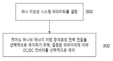
이제 도 3을 참조하면, 복수의 DC 전원으로부터 전력을 관리하는 방법의 예의 순서도가 도시된다. 단계 300에서, 하나 이상의 전자 처리 장치는 예를 들어, 각 DC/DC 컨버터의 출력 전압, DC 버스 전압, 에너지 저장 장치의 충전 한계, 에너지 저장 장치의 방전 한계, 상기 에너지 저장 장치의 SOC(state of charge) 및 상기 에너지 저장 장치의 SOH(state of health)를 포함하는 하나 이상의 시스템 파라미터를 결정한다. 상기 에너지 저장장치의 SOH는 상기 저장장치의 이상적인 상태와 비교한 상태를 나타내는 것으로, 내부저항, 용량, 전압, 자가방전, 충방전 횟수 등이 고려된다. 단계 302에서, 상기 하나 이상의 결정된 파라미터는 하나 상기 이상의 전자 처리 장치에 의해 해석되고, 상기 DC/DC 컨버터를 선택적으로 제어하여 복수의 DC 전원으로부터 하나 이상의 에너지 저장 장치로의 전력 전송을 선택적으로 제어하는 데 사용된다.Referring now to FIG. 3 , a flowchart of an example of a method for managing power from a plurality of DC power sources is shown. In step 300 , the one or more electronic processing devices determine, for example, the output voltage of each DC/DC converter, the DC bus voltage, the charge limit of the energy storage device, the discharge limit of the energy storage device, and the state of the energy storage device (SOC). charge) and one or more system parameters including a state of health (SOH) of the energy storage device. The SOH of the energy storage device represents a state compared to the ideal state of the storage device, and internal resistance, capacity, voltage, self-discharge, number of charge/discharge, and the like are considered. In
이 제어 방법을 통해 시스템은 에너지 저장 장치의 충전을 최적화하기 위해 DC 전원(예를 들어, 태양광 PV 모듈)의 출력을 조절할 수 있다. 바람직하게는, 각 DC/DC 컨버터는 아키텍처를 완전히 확장할 수 있도록 시스템 구성과 무관하게 자율적으로 제어된다.This control method allows the system to regulate the output of a DC power source (eg, a solar PV module) to optimize the charging of the energy storage device. Preferably, each DC/DC converter is autonomously controlled independent of the system configuration so that the architecture is fully scalable.
적절한 제어 방법의 구체적인 예가 도 4에 도시된다. 이 예에서, 단계 400에서 하나 이상의 처리 장치에 의해 결정된 시스템 파라미터는 배터리 최대 충전 전압이다. 상기 파라미터는 배터리에서 하나 이상의 처리 장치로 무선 전달될 수 있다. 단계 402에서, 상기 전압은 상기 하나 이상의 처리 장치에 의해 각각의 DC/DC 컨버터로 전송되거나 방송된다. 이후, 상기 전압은 각 DC/DC 컨버터에서 공통 전압 한계로 사용된다.A specific example of a suitable control method is shown in FIG. 4 . In this example, the system parameter determined by the one or more processing devices in
태양광 PV 모듈이 활성화 되어있다고 가정하면, 단계 404에서 상기 하나 이상의 처리 장치는 각 DC/DC 컨버터가 시스템의 각 PV 모듈에서 최대 전력을 얻을 수 있게 하는, MPPT(Maximum Power Point Tracking) 알고리즘과 같은 추적 알고리즘을 구현하게 한다. 각 DC/DC 컨버터는 상기 개별 DC/DC 컨버터의 전압 출력이 공통 전압 한계에 도달할 때까지 MPPT 모드에서 작동한다. 단계 406에서, 상기 하나 이상의 전자 처리 장치는 상기 각각의 DC/DC 컨버터의 전압 출력을 결정하고, 단계 408에서 각 전압 출력은 상기 공통 전압 한계와 비교된다. 특정 컨버터의 전압 출력이 공통 전압 한계 설정에 도달했다고 판단되면, 단계 410에서 상기 하나 이상의 처리 장치는 상기 출력 전압이 한계 아래로 다시 떨어지도록 상기 특정 컨버터의 전압 출력이 조절되게 한다.Assuming that the solar PV modules are active, in
예를 들어, 각 DC/DC 컨버터는 다른 컨버터가 여전히 MPPT 모드에서 작동하는 동안, 하나 이상의 컨버터의 출력이 조정될 수 있도록 독립적으로 제어된다. 이러한 방식으로, 각각의 DC/DC 컨버터는 시스템이 본질적으로 확장 가능하도록, 다른 것들이 수행하는 것과 독립적으로 제어된다. (즉, 시스템은 임의의 수의 태양광 모듈, 에너지 저장 장치 또는 인버터를 포함할 수 있음)For example, each DC/DC converter is independently controlled so that the output of one or more converters can be regulated while the other converters are still operating in MPPT mode. In this way, each DC/DC converter is controlled independently of what the others do, such that the system is inherently scalable. (i.e., the system may include any number of solar modules, energy storage devices, or inverters)
적어도 하나의 에너지 저장 장치로의 전력 전달을 선택적으로 제어하기 위해 DC/DC 컨버터를 선택적으로 제어하는 것에 더불어, 하나 이상의 처리 장치는 DC 버스와 AC 전원 사이의 전력 흐름을 선택적으로 유발하여 AC 전원의 작동 파라미터를 제어하도록 인버터를 제어하는 데 추가로 사용될 수 있다.In addition to selectively controlling the DC/DC converter to selectively control the transfer of power to the at least one energy storage device, the one or more processing devices selectively cause a flow of power between the DC bus and the AC power source to reduce the AC power supply. It may further be used to control the inverter to control the operating parameters.
이제 도 5를 참조하면, AC 전원의 하나 이상의 작동 파라미터를 제어하고자 하는 전력 분배 네트워크에서 전력을 관리하기 위한 방법의 두 번째 예가 도시된다. 단계 500에서, 상기 하나 이상의 전자 처리 장치는 AC 전원의 하나 이상의 동작 파라미터의 파라미터 값을 결정한다. 예를 들어, 상기 AC 전원이 배전 네트워크의 주 전력망인 경우, 상기 하나 이상의 작동 파라미터는 AC 전원 전압, AC 전원 주파수, 위상 부하(3상 시스템의 경우) 및 부하 역률을 포함할 수 있다. 상기 부하 역률은 유효 전력(kW) 대 피상 전력(kVA)의 비율이다. (유효 전력과 무효 전력(kVAR)의 조합). 무효 전력을 소비하거나 생성하는 부하는 실제로 부하에 전력을 공급하기 위해 작동하는, 전달된 유효 전력의 주어진 양에 대해서 상기 AC 전원에서 더 많은 전류를 끌어올 것이다. 따라서, 역률이 낮은 부하는 AC 전원에서 더 많은 전류를 끌어와 비효율적이다.Referring now to FIG. 5 , a second example of a method for managing power in a power distribution network that seeks to control one or more operating parameters of an AC power source is shown. In
하나 이상의 작동 파라미터의 하나 이상의 파라미터 값은 적절한 측정값으로부터 결정된다. 한 예에서, AC 전압 크기, AC 전류 크기 및 AC 전류 위상각의 측정은 AC 전원 미터에서 이루어지고, AC 전압 크기, AC 전류 크기 및 AC 전류 위상각의 측정은 인버터의 AC 출력에서 이루어진다. 이러한 측정에서 상기 하나 이상의 처리 장치가 상기 AC 전원의 모든 작동 파라미터를 결정할 수 있다. 예를 들어, AC 전압의 측정은 전압계, 멀티미터, 진공관 전압계(VTVM), 전계 효과 트랜지스터 전압계(FET-VM) 등을 포함하는 임의의 적절한 전압 센서를 사용하여 이루어질 수 있다. AC 전류의 측정은 멀티미터, 전류계, 피코 전류계 등을 포함하는 임의의 적절한 전류 센서를 사용하여 이루어질 수 있다.The one or more parameter values of the one or more operating parameters are determined from suitable measurements. In one example, measurements of AC voltage magnitude, AC current magnitude and AC current phase angle are made at an AC power meter, and measurements of AC voltage magnitude, AC current magnitude and AC current phase angle are made at the AC output of the inverter. Such measurements enable the one or more processing devices to determine all operating parameters of the AC power source. For example, the measurement of AC voltage can be made using any suitable voltage sensor, including a voltmeter, multimeter, tube voltmeter (VTVM), field effect transistor voltmeter (FET-VM), and the like. Measurement of AC current may be made using any suitable current sensor, including a multimeter, ammeter, picoammeter, or the like.
단계 502에서, 하나 이상의 동작 파라미터의 목표 파라미터 값은 하나 이상의 처리 장치에 의해 결정된다. 예를 들어, 상기 하나 이상의 처리 장치는 목표 파라미터 값을 나타내는 유틸리티 그리드로부터 데이터를 수신할 수 있거나, 상기 목표 값은 데이터베이스로부터 검색될 수 있다. 단계 504에서, 상기 하나 이상의 처리 장치는 상기 하나 이상의 동작 파라미터의 실제 파라미터 값과 상기 목표 파라미터 값 사이의 차이를 결정한다. 단계 506에서, 상기 하나 이상의 처리 장치는 상기 결정된 차이에 적어도 부분적으로 기반하여, 상기 인버터로 하여금 상기 에너지 저장 장치 및 상기 AC 전원 사이에 전력을 전달하도록 제어하기 위한 제어 신호를 생성한다. 상기 인버터로 또는 상기 인버터에서 발생하는 전력 흐름은 파라미터 값이 목표 파라미터 값으로 향하도록 한다. 이와 같이, 상기 에너지 저장 장치는 전력 분배 네트워크의 효율 및 전력 품질을 증가시키기 위한 전원 또는 싱크(sink)로 사용될 수 있다.At
전력 분배 네트워크에서 전력을 관리하는 방법의 특정 예가 그림 6에 도시된다. 이 예에서, 단계 600에서, 하나 이상의 처리 장치는 AC 전원의 AC 전압 레벨을 결정한다. 예를 들어, 상기 AC 전압은 상기 AC 전원 전압을 나타내는 신호를 상기 하나 이상의 처리 장치로 보내는 AC 전원 미터에 위치한 전압 센서에 의해 적절하게 측정될 수 있다. 단계 602에서, 상기 AC 전원의 목표 전압 레벨이 결정된다(목표 전압 레벨은 상한 및 하한을 갖는 수용 가능한 범위일 수 있다). 상기 AC 전원이 주 유틸리티 그리드인 경우, 유틸리티 운영자는 목표 전압 레벨을 설정한다. 단계 604에서, 상기 AC 전원의 전압 레벨과 상기 목표 전압 레벨 사이의 차이는 상기 하나 이상의 처리 장치에 의해 결정된다. A specific example of how power is managed in a power distribution network is shown in Figure 6. In this example, at
단계 606 및 608에서, 상기 하나 이상의 처리 장치는 AC 전원 전압이 목표 전압보다 크거나 작은지를 각각 결정한다. 즉, 시스템은 네트워크에 과전압 문제 또는 저전압 문제가 있는지 여부를 결정한다. 상기 과전압에 대한 응답으로, 단계 610에서 상기 하나 이상의 처리 장치는 상기 인버터가 상기 AC 전원으로부터 상기 에너지 저장 장치로 무효 전력을 싱크(sink)하게 하여 상기 AC 전원 전압을 낮추도록 하는 제어 신호를 생성한다. 상기 저전압에 응답하여, 단계 612에서 상기 하나 이상의 처리 장치는 인버터가 무효 전력을 상기 에너지 저장 장치로부터 상기 AC 전원으로 소싱(sourcing)하여 상기 AC 전원 전압을 증가시키도록 하는 제어 신호를 생성한다.In
다른 예에서, 낮은 부하 역률을 갖는 시스템의 경우 (예를 들어, 무효 전력을 소비하는 하나 이상의 유도 AC 부하가 있는 경우), 인버터는 무효 전력을 그리드에 주입하거나 부하 역률을 허용 가능한 수준으로 증가시키기 위해 부하에 직접 무효 전력을 공급하는 데 사용할 수 있다.In another example, for a system with a low load power factor (for example, there is one or more inductive AC loads consuming reactive power), the inverter injects reactive power into the grid or increases the load power factor to an acceptable level. It can be used to supply reactive power directly to the load for
다른 예에서, 인버터는 AC 전원과 동기화되기 때문에, 예를 들어, 상기 AC 전원이 손실되거나 부하에 충분한 전력을 공급할 수 없는 경우, 시스템은 하나 이상의 AC 부하에 대해 UPS(uninterrupted power supply) 기능을 제공할 수 있다. 이 예에서, 에너지 저장 장치가 충분한 용량을 갖는다고 가정하면, 상기 시스템은 상기 하나 이상의 AC 부하에 전력을 공급하기 위해 상기 에너지 저장 장치로부터 전력을 공급받을 수 있다.In another example, because the inverter is synchronized with the AC power source, the system provides an uninterrupted power supply (UPS) function for one or more AC loads, for example, if the AC power source is lost or cannot provide sufficient power to the load. can do. In this example, assuming the energy storage device has sufficient capacity, the system may be powered from the energy storage device to power the one or more AC loads.
다른 예에서, 시스템은 동적 부하 균형에 의해 3상 네트워크에서 전압 불균형을 줄이는 데 사용될 수 있다. 각 상의 전압 레벨은 적절한 전압 센서를 사용하여 측정될 수 있다. 그리고, 하나 이상의 전자 처리 장치는 이러한 측정을 기반으로 전압 레벨을 결정하며, 제어 신호를 인버터로 보내 전력이 과부하 위상에서 경부하 위상으로 전송되도록 한다. 대안적으로, 상기 인버터는 과부하된 위상의 균형을 맞추기 위해, 에너지 저장 장치에서 상기 하나 이상의 경부하 위상으로 전력 흐름(예를 들어, 무효 전력 보상)을 유발할 수 있다.In another example, the system can be used to reduce voltage imbalance in a three-phase network by dynamic load balancing. The voltage level of each phase can be measured using an appropriate voltage sensor. One or more electronic processing units then determine a voltage level based on these measurements and send a control signal to the inverter to cause power to be transferred from the overload phase to the light load phase. Alternatively, the inverter may cause power flow (eg reactive power compensation) from the energy storage device to the one or more lightly loaded phases to balance the overloaded phases.
위의 예에서, 상기 AC 전원의 작동 파라미터는 제어 계층(hierarchy)의 2계층(two-tiered) 형태에서, 에너지 저장 장치의 충전보다 우선적으로 제어될 수 있다. 예를 들어, 인버터의 제어는 에너지 저장 장치를 충전하는 DC/DC 컨버터의 제어보다 우선한다. 따라서, 상기 인버터는 상기 AC 전원의 만족스러운 작동 파라미터를 유지하기 위해, 적절하게 DC 버스와 상기 AC 전원 사이에서 전력을 싱크(sink)/소싱(sourcing)한다. 이러한 방식으로, 상기 인버터는 전원이 인버터를 통해 공급되는지, 아니면 싱크(sink)되는지 여부에 따라 상기 DC 버스 전압을 제어한다. 따라서, 상기 DC/DC 컨버터는 상기 AC 전원의 파라미터 제어에 종속되며, 따라서 상기 인버터가 상기 DC 버스에서 전력을 끌어오는 경우, 상기 DC/DC 컨버터는 MPPT 모드에서 계속 작동하여 태양광 PV 모듈의 전력 출력을 최대화하고, 상기 DC 버스 전압을 유지한다. 상기 인버터가 상기 DC 버스에서 전력을 끌어오지 않는 경우, 상기 DC/DC 컨버터는 배터리를 충전하고 최대 전압 한계에 도달할 때까지 MPPT 모드에서 동작한 뒤, 배터리 최대 충전 전압이 초과되지 않도록 출력을 조절한다. (예를 들어, 상술한 바와 같이). In the above example, the operating parameter of the AC power source may be controlled prior to charging of the energy storage device in a two-tiered form of a control hierarchy. For example, the control of the inverter takes precedence over the control of the DC/DC converter that charges the energy storage device. Accordingly, the inverter properly sinks/sources power between the DC bus and the AC power source to maintain satisfactory operating parameters of the AC power source. In this way, the inverter controls the DC bus voltage depending on whether power is supplied through the inverter or is sinking. Thus, the DC/DC converter is subject to parameter control of the AC power source, so when the inverter draws power from the DC bus, the DC/DC converter continues to operate in MPPT mode to power the solar PV module. Maximizes the output and maintains the DC bus voltage. When the inverter is not drawing power from the DC bus, the DC/DC converter charges the battery and operates in MPPT mode until the maximum voltage limit is reached, then regulates the output so that the maximum battery charge voltage is not exceeded. do. (eg, as described above).
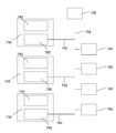
이제 도 7을 참조하면, 전력 분배 네트워크에서 전력을 관리하기 위한 시스템의 다른 예가 도시된다. 상기 시스템은 각각의 고전압 DC 버스를 통해 각각의 DC/AC 인버터에 각각 전기적으로 연결된 복수의 에너지 저장 장치(740) (예를 들어, 고전압 배터리)를 포함한다. 상기 각각의 DC/AC 인버터(760)의 출력(762)은 AC 전원(750)에 전기적으로 연결된다. 예를 들어, 상기 각각의 인버터(760)는 상기 AC 전원이 분배 급전선을 나타내는 전기 그리드의 급전선에 연결될 수 있다. 복수의 부하(780)가 그리드에 연결된다. 한 예에서, 에너지 저장 장치(740) 및 DC/AC 인버터(760) 중 적어도 하나를 포함하는 각 모듈(700)은, 전력 분배 네트워크를 지원하기 위해, 가장 잘 활용될 수 있는 피더 라인을 따라 선택적인 위치에 유틸리티 운영자에 의해 설치될 수 있다. 다른 예에서, 각 모듈(700)은 주거용으로 설치된 시스템을 나타낼 수 있다.Referring now to FIG. 7 , another example of a system for managing power in a power distribution network is shown. The system includes a plurality of energy storage devices 740 (eg, high voltage batteries) each electrically coupled to a respective DC/AC inverter via a respective high voltage DC bus. The
도 7에 도시된 배열(arrangement)에서, 각 모듈(700)은 네트워크를 지원하고 AC 전원 전압, AC 전원 주파수, 위상 부하(3상 시스템의 경우) 및 부하 역률과 같은 작동 파라미터를 개선하는 데 사용될 수 있다. 또한, 예를 들어, 상기 네트워크의 한 부분의 부하가 낮은 경우 (배터리가 충분히 충전된 경우), 상기 배터리가, 충전 수준이 낮거나 부하가 높은 네트워크의 일 부분인 다른 배터리에 전력을 공급하는 데 사용될 수 있도록, 상기 모듈(700)은 서로 통신할 수 있다.In the arrangement shown in Fig. 7, each
문맥이 달리 요구하지 않는 한, 본 명세서 및 뒤따르는 청구 범위 전반에 걸쳐, "포함하다"라는 단어 및 "포함하다" 또는 "포함하는"과 같은 변형은 명시된 정수, 또는 정수 또는 단계의 그룹을 포함하는 것을 의미하는 것으로 이해될 것이지만, 다른 정수 또는 정수의 그룹을 제외하지 않는다.Unless the context requires otherwise, throughout this specification and the claims that follow, the word "comprises" and variations such as "comprises" or "comprising" include the specified integer, or group of integers or steps. will be understood to mean, but does not exclude other integers or groups of integers.
당업자에게 수많은 변형 및 수정이 명백해질 것은 자명하다. 당업자에게 명백해지는 그러한 모든 변형 및 수정은 본 발명이 작성되기 이전에 광범위하게 나타난 정신 및 범위 내에 속하는 것으로 간주되어야 한다.Numerous variations and modifications will become apparent to those skilled in the art. All such variations and modifications that become apparent to those skilled in the art are to be considered as falling within the spirit and scope broadly indicated before the present invention was written.
Claims (35)
각각 복수의 DC(direct current) 전원 중 하나의 출력과 DC 버스 사이에 전기적으로 연결되고, 상기 DC 버스에 전기적으로 병렬로 연결되고, 및 상기 DC 전원으로부터 상기 DC 버스로 전력을 전달하도록 설정되는 복수의 DC/DC 컨버터;
상기 DC 버스에 전기적으로 연결된 적어도 하나의 DC 에너지 저장 장치;
상기 DC 버스에 전기적으로 연결된 입력 및 AC(alternating current) 부하 및 AC 전원 중 적어도 하나에 전기적으로 연결된 출력을 갖는 적어도 하나의 DC/AC 인버터; 및
상기 DC/DC 컨버터를 선택적으로 제어하여 상기 적어도 하나의 에너지 저장 장치로의 전력 전달을 선택적으로 제어하는 하나 이상의 전자 처리(processing) 장치를 포함하는, 시스템.A system for managing power in a distribution network, comprising:
a plurality of each electrically coupled between an output of one of a plurality of direct current (DC) power supplies and a DC bus, electrically coupled to the DC bus in parallel, and configured to transfer power from the DC power source to the DC bus DC/DC converter;
at least one DC energy storage device electrically coupled to the DC bus;
at least one DC/AC inverter having an input electrically coupled to the DC bus and an output electrically coupled to at least one of an alternating current (AC) load and an AC power source; and
one or more electronic processing devices for selectively controlling the DC/DC converter to selectively control power delivery to the at least one energy storage device.
상기 하나 이상의 전자 처리 장치는 컨버터 출력 전압 및 DC 버스 전압 중 적어도 하나에 따라 각 DC/DC 컨버터의 출력을 독립적으로 제어하는, 시스템.The method of claim 1,
wherein the one or more electronic processing devices independently control the output of each DC/DC converter according to at least one of a converter output voltage and a DC bus voltage.
상기 각 DC/DC 컨버터의 출력 전압은 각 컨버터의 개별 입력 전압보다 큰, 시스템.3. The method according to claim 1 or 2,
wherein the output voltage of each DC/DC converter is greater than the respective input voltage of each converter.
상기 각 DC/DC 컨버터의 출력 제어는 상기 적어도 하나의 에너지 저장 장치의 충전 한계; 상기 적어도 하나의 에너지 저장 장치의 방전 한계; 상기 적어도 하나의 에너지 저장 장치의 SOC(state of charge); 및 상기 적어도 하나의 에너지 저장 장치의 SOH(state of health) 중 적어도 하나에 따라 달라지는, 시스템.4. The method of claim 3,
The output control of each DC/DC converter may include: a charging limit of the at least one energy storage device; a discharge limit of the at least one energy storage device; a state of charge (SOC) of the at least one energy storage device; and a state of health (SOH) of the at least one energy storage device.
상기 하나 이상의 전자 처리 장치는 공통 전압 한계를 각각의 DC/DC 컨버터에 전송하는, 시스템.5. The method of claim 4,
wherein the one or more electronic processing devices transmit a common voltage limit to each DC/DC converter.
상기 공통 전압 한계는 상기 적어도 하나의 에너지 저장 장치의 최대 충전 전압을 나타내는, 시스템.6. The method of claim 5,
and the common voltage limit represents a maximum charging voltage of the at least one energy storage device.
상기 하나 이상의 전자 처리 장치는 각각의 DC/DC 컨버터가: 상기 DC/DC 컨버터의 출력이 상기 공통 전압 한계에 도달할 때까지, MPPT(maximum power point tracking) 알고리즘을 구현하게 하고; 및 상기 전압 한계에 도달하면 상기 출력을 조절하여 상기 전압 한계가 초과되지 않게 하는, 시스템.7. The method of claim 6,
the one or more electronic processing devices cause each DC/DC converter to: implement a maximum power point tracking (MPPT) algorithm until an output of the DC/DC converter reaches the common voltage limit; and regulating the output when the voltage limit is reached so that the voltage limit is not exceeded.
상기 하나 이상의 DC/DC 컨버터는 갈바닉 절연된, 시스템.according to any one of the preceding claims
wherein the one or more DC/DC converters are galvanically isolated.
상기 적어도 하나의 에너지 저장 장치는 공칭(nominal) 작동 전압이 최소 600VDC인 하나 이상의 배터리를 포함하는, 시스템.according to any one of the preceding claims,
wherein the at least one energy storage device comprises one or more batteries having a nominal operating voltage of at least 600 VDC.
상기 DC 전원은 태양광 PV(photovoltaic) 전력 모듈을 포함하는, 시스템.11. The method according to any one of claims 1 to 10,
wherein the DC power source comprises a solar photovoltaic (PV) power module.
상기 DC/DC 컨버터는 상기 PV 전력 모듈과 통합되는(integrated), 시스템.12. The method of claim 11,
wherein the DC/DC converter is integrated with the PV power module.
상기 인버터는 임피던스를 통해 상기 AC 전원에 연결된 출력을 갖는 양방향 DC/AC 인버터인, 시스템.according to any one of the preceding claims,
wherein the inverter is a bidirectional DC/AC inverter having an output coupled to the AC power source through an impedance.
상기 인버터는 분배 정적 보상기(distribution static compensator; dSTATCOM)를 포함하는, 시스템.14. The method of claim 13,
wherein the inverter comprises a distribution static compensator (dSTATCOM).
상기 인버터는 상기 DC 버스와, 상기 AC 부하 및 AC 전원 중 적어도 하나 사이에 전력이 선택적으로 흐르게 하도록 상기 하나 이상의 전자 처리 장치에 의해 제어될 수 있는, 시스템.15. The method according to claim 13 or 14,
wherein the inverter is controllable by the one or more electronic processing devices to selectively flow power between the DC bus and at least one of the AC load and the AC power source.
상기 인버터의 제어가 상기 DC/DC 컨버터의 제어보다 우선하는, 시스템.16. The method of claim 15,
and control of the inverter takes precedence over control of the DC/DC converter.
적어도, 상기 하나 이상의 전자 처리 장치, DC/DC 컨버터, 적어도 하나의 에너지 저장 장치 및 상기 인버터 사이의 무선 통신을 포함하는, 시스템.17. The method according to any one of claims 1 to 16,
and at least wireless communication between the one or more electronic processing devices, a DC/DC converter, at least one energy storage device, and the inverter.
시스템의 하나 이상의 파라미터를 결정하되,
상기 시스템은:
각각, 각각의 DC(direct current) 전원의 출력 DC 버스 사이에 전기적으로 연결되고, 상기 DC 버스에 전기적으로 병렬로 연결되고, 및 상기 DC 전원으로부터 상기 DC 버스로 전력을 전달하도록 설정되는 복수의 DC/DC 컨버터;
상기 DC 버스에 전기적으로 연결된 적어도 하나의 DC 에너지 저장 장치; 및
상기 DC 버스에 전기적으로 연결된 입력, 및 AC(alternating current) 부하 및 AC 전원 중 적어도 하나에 전기적으로 연결된 출력을 갖는 적어도 하나의 DC/AC 인버터를 포함하는, 단계; 및
상기 결정된 파라미터에 따라 상기 DC/DC 컨버터를 선택적으로 제어하여 상기 적어도 하나의 에너지 저장 장치로의 전력 전달을 선택적으로 제어하는 단계를 포함하는, 방법.A method for one or more electronic processing devices to manage power in a distribution network, the method comprising:
determine one or more parameters of the system,
The system is:
a plurality of DCs, each electrically coupled between an output DC bus of a respective direct current (DC) power source, electrically coupled in parallel to the DC bus, and configured to transfer power from the DC power source to the DC bus /DC converter;
at least one DC energy storage device electrically coupled to the DC bus; and
at least one DC/AC inverter having an input electrically coupled to the DC bus and an output electrically coupled to at least one of an alternating current (AC) load and an AC power source; and
and selectively controlling the power transfer to the at least one energy storage device by selectively controlling the DC/DC converter according to the determined parameter.
각 DC/DC 컨버터의 출력은 컨버터 출력 전압 및 DC 버스 전압 중 적어도 하나를 포함하는, 상기 결정된 파라미터에 따라 독립적으로 제어되는, 방법.19. The method of claim 18,
The output of each DC/DC converter is independently controlled according to the determined parameter comprising at least one of a converter output voltage and a DC bus voltage.
각 DC/DC 컨버터에 공통 전압 한계를 전송하는 단계를 포함하는, 방법.20. The method according to claim 18 or 19,
transmitting a common voltage limit to each DC/DC converter.
상기 DC/DC 컨버터의 출력이 상기 공통 전압 한계에 도달할 때까지, 상기 각각의 DC/DC 컨버터에서 MPPT(maximum power point tracking) 알고리즘을 구현하는 단계; 및
상기 전압 한계에 도달하면 상기 출력을 상기 전압 한계가 초과되지 않도록 조절하는 단계를 포함하는, 방법.21. The method of claim 20,
implementing a maximum power point tracking (MPPT) algorithm in each DC/DC converter until the output of the DC/DC converter reaches the common voltage limit; and
adjusting the output so that the voltage limit is not exceeded when the voltage limit is reached.
상기 DC 버스와, 상기 AC 부하 및 AC 전원 중 적어도 하나 사이에 전력이 선택적으로 흐르게 하도록 상기 인버터를 제어하는 단계를 포함하는, 방법.22. The method according to any one of claims 18 to 21,
and controlling the inverter to selectively flow power between the DC bus and at least one of the AC load and the AC power source.
상기 인버터의 제어가 상기 DC/DC 컨버터의 제어보다 우선하는, 방법.23. The method of claim 22,
and the control of the inverter takes precedence over the control of the DC/DC converter.
상기 AC 전원의 하나 이상의 작동 파라미터를 결정하는 단계;
상기 하나 이상의 작동 파라미터의 목표 파라미터 값을 결정하는 단계;
상기 파라미터 값과 목표 파라미터 값의 차이를 결정하는 단계; 및
상기 결정된 차이에 적어도 부분적으로 기반하여, 상기 인버터를 제어함으로써 상기 DC 버스 및 상기 AC 전원 사이에, 상기 파라미터 값이 상기 목표 파라미터 값을 향하도록 하는, 전력 흐름을 선택적으로 유발하기 위한 제어 신호를 생성하는 단계를 포함하는, 방법.24. The method according to any one of claims 18 to 23,
determining one or more operating parameters of the AC power source;
determining a target parameter value of the one or more operating parameters;
determining a difference between the parameter value and a target parameter value; and
based at least in part on the determined difference, generating a control signal for selectively causing a power flow between the DC bus and the AC power supply by controlling the inverter to direct the parameter value towards the target parameter value A method comprising the step of
상기 AC 전원의 상기 하나 이상의 작동 파라미터는 AC 전원 주파수, AC 전원 전압, 위상 로딩(loading), 및 부하 역률 중 적어도 하나를 포함하는, 방법.25. The method of claim 24,
and the one or more operating parameters of the AC power source include at least one of an AC power supply frequency, an AC supply voltage, a phase loading, and a load power factor.
상기 AC 전원은 유틸리티 그리드 또는 발전기 중 적어도 하나를 포함하는, 방법.26. The method of claim 25,
The AC power source comprises at least one of a utility grid or a generator.
상기 적어도 하나의 전자 처리(processing) 장치가 상기 파라미터 값을 결정하는 단계는:
상기 인버터 출력에서의 AC 전압 크기(magnitude), AC 전류 크기 및 AC 전류 위상 각의 측정된 값을 결정하는 단계; 및
상기 AC 전원에서의 AC 전압 크기, AC 전류 크기 및 AC 전류 위상 각의 측정된 값을 결정하는 단계를 포함하는 방법.27. The method according to any one of claims 24-26,
determining, by the at least one electronic processing device, the parameter value:
determining measured values of AC voltage magnitude, AC current magnitude and AC current phase angle at the inverter output; and
determining measured values of AC voltage magnitude, AC current magnitude and AC current phase angle at the AC power source.
상기 제어 신호는 상기 인버터가:
상기 AC 전원으로부터 상기 DC 버스로의 전력 흐름을 유발; 및
상기 DC 버스로부터 상기 AC 전원으로의 전력 흐름을 유발 중 적어도 하나를 하게 하는, 방법.28. The method according to any one of claims 24 to 27,
The control signal is the inverter:
causing power flow from the AC power source to the DC bus; and
causing at least one of inducing a flow of power from the DC bus to the AC power source.
상기 제어 신호는 상기 인버터가 상기 DC 버스로부터 상기 적어도 하나의 AC 부하로의 전력 흐름을 유발하게 하는, 방법.29. The method according to any one of claims 24-28,
and the control signal causes the inverter to cause power flow from the DC bus to the at least one AC load.
상기 전력 흐름은 유효 전력(real power, kW) 및 무효 전력(reactive power, kVAR) 중 적어도 하나를 포함하는 방법.30. The method of claim 28 or 29,
The power flow comprises at least one of real power (kW) and reactive power (kVAR).
상기 인버터가 상기 적어도 하나의 AC 부하의 작동을 제어하는 하나 이상의 스위칭 장치를 작동하게 하는 제어 신호를 생성하는 단계를 포함하는, 방법.31. The method of claim 29 or 30,
generating a control signal causing the inverter to operate one or more switching devices that control operation of the at least one AC load.
상기 적어도 하나의 전자 처리 장치는 상기 인버터 출력이 상기 AC 전원과 동기화 되게 하는, 방법.32. The method according to any one of claims 18 to 31,
and the at least one electronic processing device causes the inverter output to be synchronized with the AC power source.
적어도 상기 하나 이상의 전자 처리 장치, 상기 인버터, 상기 에너지 저장 장치, 상기 적어도 하나의 AC 부하, 상기 AC 전원 및 하나 이상의 외부 통신 네트워크는 무선 통신을 통해 제어되는, 방법.33. The method according to any one of claims 24-32,
wherein at least the one or more electronic processing devices, the inverter, the energy storage device, the at least one AC load, the AC power source, and the one or more external communication networks are controlled via wireless communication.
상기 제어 신호는 적어도 부분적으로 머신 러닝(machine learning) 알고리즘에 의해, 또는 상기 AC 전원의 상기 하나 이상의 작동 파라미터의 이력(historical) 데이터로부터 생성되는, 방법.according to any one of the preceding claims,
wherein the control signal is generated, at least in part, by a machine learning algorithm, or from historical data of the one or more operating parameters of the AC power source.
상기 결정된 차이에 적어도 부분적으로 기반하여, 복수의 인버터를 제어함으로써 복수의 에너지 저장 장치 및 상기 AC 전원 사이에, 상기 파라미터 값이 상기 목표 파라미터 값을 향하도록 하는, 전력 흐름을 선택적으로 유발하기 위한 복수의 제어 신호를 생성하는 단계를 포함하는, 방법.35. The method of any one of claims 24-34,
a plurality of for selectively causing a power flow between a plurality of energy storage devices and the AC power source by controlling a plurality of inverters to direct the parameter value toward the target parameter value based at least in part on the determined difference generating a control signal of
Applications Claiming Priority (3)
| Application Number | Priority Date | Filing Date | Title |
|---|---|---|---|
| AU2019900446A AU2019900446A0 (en) | 2019-02-12 | System and method for managing power | |
| AU2019900446 | 2019-02-12 | ||
| PCT/AU2020/050117 WO2020163912A1 (en) | 2019-02-12 | 2020-02-12 | System and method for managing power |
Publications (1)
| Publication Number | Publication Date |
|---|---|
| KR20210149697A true KR20210149697A (en) | 2021-12-09 |
Family
ID=72043766
Family Applications (1)
| Application Number | Title | Priority Date | Filing Date |
|---|---|---|---|
| KR1020217029050A KR20210149697A (en) | 2019-02-12 | 2020-02-12 | Systems and methods for managing power |
Country Status (8)
| Country | Link |
|---|---|
| US (1) | US20220263311A1 (en) |
| EP (1) | EP3925050A4 (en) |
| JP (1) | JP2022520597A (en) |
| KR (1) | KR20210149697A (en) |
| CN (1) | CN113692684A (en) |
| AU (1) | AU2020222505A1 (en) |
| CA (1) | CA3133021A1 (en) |
| WO (1) | WO2020163912A1 (en) |
Families Citing this family (4)
| Publication number | Priority date | Publication date | Assignee | Title |
|---|---|---|---|---|
| CN112886630B (en) * | 2021-04-29 | 2021-07-30 | 广东电网有限责任公司阳江供电局 | Island voltage control method based on flexible direct current transmission parallel operation system |
| CN117099281A (en) * | 2021-08-26 | 2023-11-21 | 华为数字能源技术有限公司 | Electric power system and control method for electric power system |
| CN116780668A (en) * | 2022-01-10 | 2023-09-19 | 何小平 | Integrated high-voltage equipment and high-frequency energy-transfer power supply device and integrated method |
| SE545936C2 (en) * | 2022-07-29 | 2024-03-19 | Heart Aerospace AB | An energy distribution system |
Family Cites Families (20)
| Publication number | Priority date | Publication date | Assignee | Title |
|---|---|---|---|---|
| US9093862B2 (en) * | 2009-01-16 | 2015-07-28 | Zbb Energy Corporation | Method and apparatus for controlling a hybrid power system |
| KR101146670B1 (en) * | 2009-12-16 | 2012-05-23 | 삼성에스디아이 주식회사 | Energy management system and method for controlling thereof |
| JPWO2011074661A1 (en) * | 2009-12-17 | 2013-05-02 | 三洋電機株式会社 | Charge / discharge system |
| US9331499B2 (en) * | 2010-08-18 | 2016-05-03 | Volterra Semiconductor LLC | System, method, module, and energy exchanger for optimizing output of series-connected photovoltaic and electrochemical devices |
| US20120326516A1 (en) * | 2011-06-27 | 2012-12-27 | Bloom Energy Corporation | Fuel Cell Power Generation System with Isolated and Non-Isolated Buses |
| NZ630003A (en) * | 2012-11-23 | 2017-03-31 | Elevare Energy Ip Pty Ltd | Electrical supply system |
| CN103944492A (en) * | 2014-05-08 | 2014-07-23 | 阳光电源股份有限公司 | Inverter and photovoltaic power generation system |
| US10926649B2 (en) * | 2014-12-22 | 2021-02-23 | Flex Power Control, Inc. | Method to reduce losses in a high voltage DC link converter |
| CN106877368A (en) * | 2015-12-13 | 2017-06-20 | 姚秋丽 | A kind of photovoltaic generation micro-grid system hybrid energy-storing control method |
| CN106877379A (en) * | 2015-12-14 | 2017-06-20 | 韩会义 | A kind of parallel network power generation power stabilizes control method |
| CN205646811U (en) * | 2016-05-24 | 2016-10-12 | 中广核太阳能开发有限公司 | Photovoltaic directly exchanges and mixes little grid system |
| JP6765078B2 (en) * | 2017-03-30 | 2020-10-07 | パナソニックIpマネジメント株式会社 | Power converter, power conversion system |
| US10541535B2 (en) * | 2017-04-18 | 2020-01-21 | Kilowatt Labs, Inc. | Apparatus and method for aggregating and supplying energy to a load |
| JP7248593B2 (en) * | 2017-05-15 | 2023-03-29 | ダイナパワー カンパニー エルエルシー | Surplus power extraction method and system |
| EP3472914B1 (en) * | 2017-05-15 | 2020-06-10 | Dynapower Company Llc | Energy storage system for photovoltaic energy and method of storing photovoltaic energy |
| JP6834800B2 (en) * | 2017-06-20 | 2021-02-24 | 住友電気工業株式会社 | Power conditioner, double power generation system, and control method of double power generation system |
| US11092652B2 (en) * | 2018-01-03 | 2021-08-17 | Bloom Energy Corporation | Grid islanded fuel cell installation for data center load |
| CN109167377A (en) * | 2018-10-09 | 2019-01-08 | 上海博阳新能源科技股份有限公司 | Electric charging station system is stored up using the light of battery based on echelon |
| KR20210145139A (en) * | 2019-02-12 | 2021-12-01 | 일렉시스 아이피 피티와이 엘티디 | Systems and methods for power management in power distribution networks |
| US20230420936A1 (en) * | 2022-06-24 | 2023-12-28 | Bloom Energy Corporation | Control systems and methods for minimizing power loss associated with fuel cell systems |
-
2020
- 2020-02-12 WO PCT/AU2020/050117 patent/WO2020163912A1/en unknown
- 2020-02-12 JP JP2021547325A patent/JP2022520597A/en active Pending
- 2020-02-12 CA CA3133021A patent/CA3133021A1/en active Pending
- 2020-02-12 KR KR1020217029050A patent/KR20210149697A/en active Search and Examination
- 2020-02-12 AU AU2020222505A patent/AU2020222505A1/en active Pending
- 2020-02-12 US US17/430,187 patent/US20220263311A1/en active Pending
- 2020-02-12 CN CN202080020771.0A patent/CN113692684A/en active Pending
- 2020-02-12 EP EP20755924.6A patent/EP3925050A4/en active Pending
Also Published As
| Publication number | Publication date |
|---|---|
| WO2020163912A1 (en) | 2020-08-20 |
| EP3925050A1 (en) | 2021-12-22 |
| US20220263311A1 (en) | 2022-08-18 |
| EP3925050A4 (en) | 2022-12-07 |
| JP2022520597A (en) | 2022-03-31 |
| CN113692684A (en) | 2021-11-23 |
| AU2020222505A1 (en) | 2021-10-07 |
| CA3133021A1 (en) | 2020-08-20 |
Similar Documents
| Publication | Publication Date | Title |
|---|---|---|
| US10756546B2 (en) | Methods of advanced grid and microgrid support functionalities through hybrid fuel cell systems | |
| US9882528B2 (en) | Distributed energy storage and power quality control in photovoltaic arrays | |
| US10727669B2 (en) | Apparatuses including power electronics circuitry, and related methods of operation | |
| KR20210149697A (en) | Systems and methods for managing power | |
| Rahman et al. | Coordinated control of three-phase AC and DC type EV–ESSs for efficient hybrid microgrid operations | |
| US20210075221A1 (en) | Real time energy management and control of renewable energy based microgrid in grid-connected and island modes | |
| US20170201098A1 (en) | Photovoltaic microstorage microinverter | |
| CN102237689A (en) | System for interchanging electric energy between a battery and an electric grid and respective method and application | |
| Serban et al. | A look at the role and main topologies of battery energy storage systems for integration in autonomous microgrids | |
| Heidary et al. | Stability enhancement and energy management of AC-DC microgrid based on active disturbance rejection control | |
| Jiang et al. | Power management strategy for microgrid with energy storage system | |
| Tan et al. | Control of parallel inverter-interfaced distributed generation systems in microgrid for islanded operation | |
| WO2020218191A1 (en) | Power control device, method of controlling power control device, and distributed power generation system | |
| di Piazza et al. | Electrical storage integration into a DC nanogrid testbed for smart home applications | |
| US20220200283A1 (en) | System and Method for Managing Power in an Electrical Power Distribution Network | |
| KR20200079606A (en) | Control system of DC Uninterruptible Power Supply for load distribution | |
| JP2019165552A (en) | Centralized management device | |
| Petreus et al. | Microgrid concept based on distributed renewable generators for a greenhouse | |
| Choudhury et al. | Overview of DC microgrid as a conceivable future power system | |
| Kelm et al. | Effectiveness of Energy Storage Application for improving the quality of supply in Low Voltage Networks with Distributed Generation | |
| Krishan et al. | Voltage regulation of residential DC distribution feeder using coordinated battery energy storage units | |
| Raviteja et al. | Power Management Scheme For Wind-PV-Battery-Based Hybrid Micro Grids For Power Control | |
| Soni et al. | Transient performance study in a rural microgrid: Influence of various energy storage options | |
| Kusmantoro et al. | Solar power and multi-battery for new configuration DC microgrid using centralized control | |
| Chakraborty et al. | Hierarchical Control of Stand Alone Microgrid for Peak and off-peak Hours Operation |
Legal Events
| Date | Code | Title | Description |
|---|---|---|---|
| A201 | Request for examination |