KR20170138167A - Device for measuring a loss in a reactive power compensation system - Google Patents
Device for measuring a loss in a reactive power compensation system Download PDFInfo
- Publication number
- KR20170138167A KR20170138167A KR1020160070213A KR20160070213A KR20170138167A KR 20170138167 A KR20170138167 A KR 20170138167A KR 1020160070213 A KR1020160070213 A KR 1020160070213A KR 20160070213 A KR20160070213 A KR 20160070213A KR 20170138167 A KR20170138167 A KR 20170138167A
- Authority
- KR
- South Korea
- Prior art keywords
- unit
- reactive power
- loss
- current
- voltage
- Prior art date
Links
Images

Classifications
-
- G—PHYSICS
- G01—MEASURING; TESTING
- G01R—MEASURING ELECTRIC VARIABLES; MEASURING MAGNETIC VARIABLES
- G01R11/00—Electromechanical arrangements for measuring time integral of electric power or current, e.g. of consumption
- G01R11/48—Meters specially adapted for measuring real or reactive components; Meters specially adapted for measuring apparent energy
- G01R11/52—Meters specially adapted for measuring real or reactive components; Meters specially adapted for measuring apparent energy for measuring reactive component
-
- G—PHYSICS
- G01—MEASURING; TESTING
- G01R—MEASURING ELECTRIC VARIABLES; MEASURING MAGNETIC VARIABLES
- G01R21/00—Arrangements for measuring electric power or power factor
- G01R21/001—Measuring real or reactive component; Measuring apparent energy
- G01R21/003—Measuring reactive component
-
- G—PHYSICS
- G01—MEASURING; TESTING
- G01R—MEASURING ELECTRIC VARIABLES; MEASURING MAGNETIC VARIABLES
- G01R27/00—Arrangements for measuring resistance, reactance, impedance, or electric characteristics derived therefrom
- G01R27/02—Measuring real or complex resistance, reactance, impedance, or other two-pole characteristics derived therefrom, e.g. time constant
- G01R27/26—Measuring inductance or capacitance; Measuring quality factor, e.g. by using the resonance method; Measuring loss factor; Measuring dielectric constants ; Measuring impedance or related variables
- G01R27/2688—Measuring quality factor or dielectric loss, e.g. loss angle, or power factor
- G01R27/2694—Measuring dielectric loss, e.g. loss angle, loss factor or power factor
-
- G—PHYSICS
- G01—MEASURING; TESTING
- G01R—MEASURING ELECTRIC VARIABLES; MEASURING MAGNETIC VARIABLES
- G01R15/00—Details of measuring arrangements of the types provided for in groups G01R17/00 - G01R29/00, G01R33/00 - G01R33/26 or G01R35/00
- G01R15/14—Adaptations providing voltage or current isolation, e.g. for high-voltage or high-current networks
- G01R15/16—Adaptations providing voltage or current isolation, e.g. for high-voltage or high-current networks using capacitive devices
-
- G—PHYSICS
- G01—MEASURING; TESTING
- G01R—MEASURING ELECTRIC VARIABLES; MEASURING MAGNETIC VARIABLES
- G01R15/00—Details of measuring arrangements of the types provided for in groups G01R17/00 - G01R29/00, G01R33/00 - G01R33/26 or G01R35/00
- G01R15/14—Adaptations providing voltage or current isolation, e.g. for high-voltage or high-current networks
- G01R15/18—Adaptations providing voltage or current isolation, e.g. for high-voltage or high-current networks using inductive devices, e.g. transformers
-
- G—PHYSICS
- G01—MEASURING; TESTING
- G01R—MEASURING ELECTRIC VARIABLES; MEASURING MAGNETIC VARIABLES
- G01R19/00—Arrangements for measuring currents or voltages or for indicating presence or sign thereof
- G01R19/25—Arrangements for measuring currents or voltages or for indicating presence or sign thereof using digital measurement techniques
- G01R19/2513—Arrangements for monitoring electric power systems, e.g. power lines or loads; Logging
-
- G—PHYSICS
- G01—MEASURING; TESTING
- G01R—MEASURING ELECTRIC VARIABLES; MEASURING MAGNETIC VARIABLES
- G01R21/00—Arrangements for measuring electric power or power factor
- G01R21/06—Arrangements for measuring electric power or power factor by measuring current and voltage
-
- G—PHYSICS
- G01—MEASURING; TESTING
- G01R—MEASURING ELECTRIC VARIABLES; MEASURING MAGNETIC VARIABLES
- G01R21/00—Arrangements for measuring electric power or power factor
- G01R21/133—Arrangements for measuring electric power or power factor by using digital technique
- G01R21/1331—Measuring real or reactive component, measuring apparent energy
-
- G—PHYSICS
- G01—MEASURING; TESTING
- G01R—MEASURING ELECTRIC VARIABLES; MEASURING MAGNETIC VARIABLES
- G01R25/00—Arrangements for measuring phase angle between a voltage and a current or between voltages or currents
- G01R25/005—Circuits for comparing several input signals and for indicating the result of this comparison, e.g. equal, different, greater, smaller, or for passing one of the input signals as output signal
-
- H—ELECTRICITY
- H02—GENERATION; CONVERSION OR DISTRIBUTION OF ELECTRIC POWER
- H02J—CIRCUIT ARRANGEMENTS OR SYSTEMS FOR SUPPLYING OR DISTRIBUTING ELECTRIC POWER; SYSTEMS FOR STORING ELECTRIC ENERGY
- H02J3/00—Circuit arrangements for ac mains or ac distribution networks
- H02J3/18—Arrangements for adjusting, eliminating or compensating reactive power in networks
- H02J3/1821—Arrangements for adjusting, eliminating or compensating reactive power in networks using shunt compensators
- H02J3/1835—Arrangements for adjusting, eliminating or compensating reactive power in networks using shunt compensators with stepless control
- H02J3/1864—Arrangements for adjusting, eliminating or compensating reactive power in networks using shunt compensators with stepless control wherein the stepless control of reactive power is obtained by at least one reactive element connected in series with a semiconductor switch
-
- Y—GENERAL TAGGING OF NEW TECHNOLOGICAL DEVELOPMENTS; GENERAL TAGGING OF CROSS-SECTIONAL TECHNOLOGIES SPANNING OVER SEVERAL SECTIONS OF THE IPC; TECHNICAL SUBJECTS COVERED BY FORMER USPC CROSS-REFERENCE ART COLLECTIONS [XRACs] AND DIGESTS
- Y02—TECHNOLOGIES OR APPLICATIONS FOR MITIGATION OR ADAPTATION AGAINST CLIMATE CHANGE
- Y02E—REDUCTION OF GREENHOUSE GAS [GHG] EMISSIONS, RELATED TO ENERGY GENERATION, TRANSMISSION OR DISTRIBUTION
- Y02E40/00—Technologies for an efficient electrical power generation, transmission or distribution
- Y02E40/30—Reactive power compensation
Landscapes
- Physics & Mathematics (AREA)
- General Physics & Mathematics (AREA)
- Engineering & Computer Science (AREA)
- Power Engineering (AREA)
- Supply And Distribution Of Alternating Current (AREA)
- Control Of Electrical Variables (AREA)
- Remote Monitoring And Control Of Power-Distribution Networks (AREA)
Abstract
Description
본 발명은 무효 전력 보상 시스템에 관한 것으로, 특히 무효 전력 보상 시스템의 손실 측정 장치에 관한 것이다.BACKGROUND OF THE
부하가 연결되어 있는 수전단에 전력이 공급되는 경우, 해당 전력이 모두 부하에 사용되지 않게 된다. 다시 말해, 해당 전력은 모두 유효전력으로서 부하에 사용되지 않고, 해당 전력 중 일부는 실제 일에 기여하지 않는 무효전력으로 손실되게 된다.When power is supplied to the load front end, all of the power is not used for the load. In other words, all of the power is not used for the load as active power, and some of the power is lost as reactive power which does not contribute to the actual work.
이러한 무효전력을 최소화시키거나 보상시키기 위해 무효 전력 보상 시스템이 채택된다.A reactive power compensation system is adopted to minimize or compensate for such reactive power.
무효 전력 보상 시스템에 의해 전압의 위상이나 전류의 위상이 조절되어 무효 전력이 최소화될 수 있다. The reactive power compensation system adjusts the phase of the voltage or the phase of the current so that the reactive power can be minimized.
한편, 무효 전력 보상 시스템에 구성된 기기들로 인한 손실이 발생하게 된다. On the other hand, losses due to the devices configured in the reactive power compensation system occur.
하지만, 종래에는 무효 전력 보상 시스템 내에 구성된 다양한 기기들에 의해 손실이 얼마나 발생되는지를 파악할 수 없는 문제점이 있다. However, there is a problem that it is not possible to grasp how many losses are generated by various devices configured in the reactive power compensation system.
따라서, 무효 전력 보상 시스템의 구매자 측면에서는 무효 전력 보상 시스템의 구매에 대한 경제성 판단을 할 수 없고, 나아가 무효 전력 보상 시스템으로 인한 손실을 지속적으로 파악하여, 그에 따른 대응 방안을 강구할 수 없는 문제점이 있다.Therefore, in the buyer aspect of the reactive power compensation system, it is not possible to determine the economical efficiency of the purchase of the reactive power compensation system, and furthermore, the loss due to the reactive power compensation system is constantly grasped, have.
또한, 무효 전력 보상 시스템의 제조자 측면에서는 무효 전력 보상 시스템의 손실 파악이 안돼, 구매자의 손실에 대한 문의에 대해 답변을 할 수 없어 해당 제품 판매에 대한 신뢰성을 구매자에게 홍보하기 어려운 문제점이 있다.In addition, in the manufacturer side of the reactive power compensation system, loss of the reactive power compensation system can not be grasped and the inquiry about the loss of the buyer can not be answered, so that it is difficult to promote the reliability of the product sale to the buyer.
아울러, 무효 전력 보상 시스템의 유지 보수 및 손실량을 설계에 반영하기 위해서는 무효 전력 보상 시스템의 손실을 파악해야 하는데, 종래에는 무효 전력 보상 시스템의 손실을 파악할 수 없는 문제점이 있다.In addition, in order to reflect the maintenance and loss amount of the reactive power compensation system in the design, it is necessary to grasp the loss of the reactive power compensation system. In the past, there is a problem that loss of the reactive power compensation system can not be grasped.
따라서, 무효 전력 보상 시스템의 손실을 파악하지 못하므로, 무효 전력 보상 시스템을 포함한 전체 시스템에 대한 정확한 평가가 어려우며, 차기 시스템 설계 시에 해당 손실 등이 반영될 수 없는 문제점이 있다.Therefore, since the loss of the reactive power compensation system can not be grasped, it is difficult to accurately evaluate the entire system including the reactive power compensation system, and the corresponding loss can not be reflected in the design of the next system.
본 발명은 전술한 문제 및 다른 문제를 해결하는 것을 목적으로 한다.The present invention is directed to solving the above-mentioned problems and other problems.
본 발명의 다른 목적은 무효 전력 보상 시스템에 포함된 다양한 기기의 손실을 파악할 수 있도록 하는 무효 전력 보상 시스템의 손실 측정 장치를 제공한다.Another object of the present invention is to provide a loss measurement apparatus for a reactive power compensation system that enables to detect losses of various devices included in the reactive power compensation system.
상기 또는 다른 목적을 달성하기 위해 본 발명의 일 측면에 따르면, 무효 전력 보상 시스템의 손실 측정 장치는 적어도 하나 이상의 부하, 무효 전력 보상부, 적어도 하나 이상의 검출부, 측정부 및 손실 계산부를 포함할 수 있다.According to an aspect of the present invention, there is provided a loss measurement apparatus for a reactive power compensation system, including at least one load, a reactive power compensation unit, at least one detection unit, a measurement unit, and a loss calculation unit .
상기 적어도 하나 이상의 부하는 수전단에 연결될 수 있다. The at least one load may be connected to the front end.
상기 무효 전력 보상부는 상기 수전단에 연결되고 적어도 하나 이상의 기기를 포함할 수 있다. The reactive power compensating unit may include at least one device connected to the receiver.
상기 적어도 하나 이상의 검출부는 상기 적어도 하나 이상의 기기에 설치되어 전압, 전압의 위상, 전류 및 전류의 위상을 검출할 수 있다.The at least one detector may be installed in the at least one or more devices to detect phases of voltages, voltages, currents, and currents.
상기 측정부는 상기 적어도 하나 이상의 검출부로부터 검출된 전압, 전압의 위상, 전류 및 전류의 위상을 토대로 전압 데이터, 전류 데이터 및 위상각을 측정할 수 있다. The measuring unit may measure the voltage data, the current data, and the phase angle based on the phase of the voltage, the phase of the voltage, the current and the current detected from the at least one detecting unit.
상기 손실 계산부는 상기 측정된 전압 데이터, 전류 데이터 및 위상각을 토대로 상기 적어도 하나 이상의 기기의 손실 전력을 계산할 수 있다.The loss calculator may calculate the loss power of the at least one or more devices based on the measured voltage data, current data, and phase angle.
본 발명에 따른 무효 전력 보상 시스템의 손실 측정 장치의 효과에 대해 설명하면 다음과 같다.The effect of the loss measuring apparatus of the reactive power compensation system according to the present invention will be described as follows.
본 발명의 실시 예들 중 적어도 하나에 의하면, 무효 전력 보상 시스템의 손실을 용이하게 파악할 수 있고 해당 손실을 지속적으로 그리고 실시간으로 파악할 수 있다는 장점이 있다.According to at least one of the embodiments of the present invention, the loss of the reactive power compensation system can be easily grasped and the loss can be grasped continuously and in real time.
또한, 본 발명의 실시 예들 중 적어도 하나에 의하면, 무효 전력 보상 시스템의 구매자나 운용자 입장에서는 해당 손실에 따른 경제성 판단이 가능하며 해당 무효 전력 보상 시스템의 손실 증가 등을 파악하여 해당 무효 전력 보상 시스템의 노후 정도 및 교체 주기를 파악할 수 있다는 장점이 있다.According to at least one of the embodiments of the present invention, the buyer or the operator of the reactive power compensation system can determine the economics based on the loss in the case of the purchaser or the operator, grasps the loss increase of the reactive power compensation system, The degree of aging and the cycle of replacement can be grasped.
본 발명의 실시 예들 중 적어도 하나에 의하면, 무효 전력 보상 시스템을 판매한 제조자 입장에서는 해당 무효 전력 보상 시스템의 무효 전력 보상뿐만 아니라 손실 파악도 가능함을 홍보하여 보다 많이 해당 무효 전력 보상 시스템을 판매할 수 있다는 장점이 있다. According to at least one of the embodiments of the present invention, a manufacturer who sells the reactive power compensation system can promote the reactive power compensation system of the corresponding reactive power compensation system, .
본 발명의 실시 예들 중 적어도 하나에 의하면, 무효 전력 보상 시스템의 손실 측정 장치를 통해 사용되는 부하의 개수에 따라 달라지는 무효 전력 보상 시스템의 손실 측정이 가능하여, 이에 대한 평가나 대응 방안이 용이하게 모색될 수 있다는 장점이 있다. According to at least one of the embodiments of the present invention, it is possible to measure the loss of the reactive power compensation system, which varies depending on the number of loads used through the loss measuring device of the reactive power compensation system, There is an advantage that it can be.
본 발명의 적용 가능성의 추가적인 범위는 이하의 상세한 설명으로부터 명백해질 것이다. 그러나 본 발명의 사상 및 범위 내에서 다양한 변경 및 수정은 당업자에게 명확하게 이해될 수 있으므로, 상세한 설명 및 본 발명의 바람직한 실시 예와 같은 특정 실시 예는 단지 예시로 주어진 것으로 이해되어야 한다. Further scope of applicability of the present invention will become apparent from the following detailed description. It should be understood, however, that the detailed description and specific examples, such as the preferred embodiments of the invention, are given by way of illustration only, since various changes and modifications within the spirit and scope of the invention will become apparent to those skilled in the art.
도 1은 본 발명의 일 실시예에 따른 무효 전력 보상 시스템의 손실 측정 장치를 도시한 도면이다.
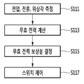
도 2는 무효 전력 보상 시스템의 보상 방법을 설명하는 순서도이다.1 is a diagram illustrating a loss measuring apparatus of a reactive power compensation system according to an embodiment of the present invention.
2 is a flowchart illustrating a compensation method of the reactive power compensation system.
이하, 첨부된 도면을 참조하여 본 명세서에 개시된 실시 예를 상세히 설명하되, 도면 부호에 관계없이 동일하거나 유사한 구성요소는 동일한 참조 번호를 부여하고 이에 대한 중복되는 설명은 생략하기로 한다. 이하의 설명에서 사용되는 구성요소에 대한 접미사 "모듈" 및 "부"는 명세서 작성의 용이함만이 고려되어 부여되거나 혼용되는 것으로서, 그 자체로 서로 구별되는 의미 또는 역할을 갖는 것은 아니다. 또한, 본 명세서에 개시된 실시 예를 설명함에 있어서 관련된 공지 기술에 대한 구체적인 설명이 본 명세서에 개시된 실시 예의 요지를 흐릴 수 있다고 판단되는 경우 그 상세한 설명을 생략한다. 또한, 첨부된 도면은 본 명세서에 개시된 실시 예를 쉽게 이해할 수 있도록 하기 위한 것일 뿐, 첨부된 도면에 의해 본 명세서에 개시된 기술적 사상이 제한되지 않으며, 본 발명의 사상 및 기술 범위에 포함되는 모든 변경, 균등물 내지 대체물을 포함하는 것으로 이해되어야 한다. Hereinafter, embodiments of the present invention will be described in detail with reference to the accompanying drawings, wherein like reference numerals are used to designate identical or similar elements, and redundant description thereof will be omitted. The suffix "module" and " part "for the components used in the following description are given or mixed in consideration of ease of specification, and do not have their own meaning or role. In the following description of the embodiments of the present invention, a detailed description of related arts will be omitted when it is determined that the gist of the embodiments disclosed herein may be blurred. It is to be understood that both the foregoing general description and the following detailed description are exemplary and explanatory and are intended to provide further explanation of the invention as claimed. , ≪ / RTI > equivalents, and alternatives.
도 1은 본 발명의 일 실시예에 따른 무효 전력 보상 시스템의 손실 측정 장치를 도시한 도면이다.1 is a diagram illustrating a loss measuring apparatus of a reactive power compensation system according to an embodiment of the present invention.
도 1을 참조하면, 무효 전력 보상 시스템의 손실 측정 장치는 무효 전력 보상부(30) 및 제어 시스템(40)를 포함한다.Referring to FIG. 1, the loss measurement apparatus of the reactive power compensation system includes a
수전단(11)에 다수의 부하(21a, 21b, 21c, 23a, 23b, 23c)가 연결될 수 있다. 구체적으로, 수전단(11)으로부터 지선(12)이 분기되어 연결되고, 이 지선(12)에 다수의 부하(21a, 21b, 21c, 23a, 23b, 23c)가 연결될 수 있다. A plurality of loads 21a, 21b, 21c, 23a, 23b, and 23c can be connected to the receiving end 11. More specifically, the branch line 12 is branched from the receiving end 11, and a plurality of loads 21a, 21b, 21c, 23a, 23b, and 23c can be connected to the branch line 12. [
도 1에서는 지선(12)이 수전단(11)에 연결되는 것으로 도시되고 있지만, 지선(12) 없이 다수의 부하(21a, 21b, 21c, 23a, 23b, 23c)가 직접 수전단(11)에 연결될 수도 있다. A plurality of loads 21a, 21b, 21c, 23a, 23b and 23c are directly connected to the receiving end 11 without the branch wire 12, although the branch wire 12 is shown connected to the receiving end 11 in Fig. Lt; / RTI >
상기 수전단(11) 이외에 계통에 부하(21a, 21b, 21c, 23a, 23b, 23c)가 연결될 수도 있다. 계통은 AC 계통, DC 계통, HVDC 계통일 수 있지만, 이에 대해서는 한정하지 않는다. The loads 21a, 21b, 21c, 23a, 23b, and 23c may be connected to the system other than the receiving end 11. The system may be an AC system, a DC system, or an HVDC system, but is not limited thereto.
부하(21a, 21b, 21c, 23a, 23b, 23c)는 일 예로서 제철소에 구비된 부하로서, 예컨대 아크로(21a, 21b, 21c)나 정련로(23a, 23b, 23c)일 수 있지만, 이에 대해서는 한정하지 않는다. The loads 21a, 21b, 21c, 23a, 23b and 23c may be, for example, arcs 21a, 21b and 21c and refining furnaces 23a, 23b and 23c, Not limited.
무효 전력 보상부(30)은 부하(21a, 21b, 21c, 23a, 23b, 23c)와 병렬로 연결되는 한편 부하(21a, 21b, 21c, 23a, 23b, 23c)와 지선(12) 또는 수전단(11)에 공통 연결될 수 있지만, 이에 대해서는 한정하지 않는다. 이에 따라, 수전단(11)으로 공급되는 전력은 다수의 부하(21a, 21b, 21c, 23a, 23b, 23c)뿐만 아니라 무효 전력 보상부(30)으로 공급될 수 있다. The reactive
무효 전력 보상부(30)은 유도성 보상부(25), 용량성 보상부(27) 및 고조파 필터부(29)를 포함할 수 있다.The reactive
유도성 보상부(TCR: Thyristor-Controlled Reactor, 25)는 리액터 소자와 사이리스터 스위치(thyristor switch)를 포함할 수 있다. 리액터 소자의 개수나 배열은 다양한 방법에 의해 구현 가능하다.The thyristor-controlled reactor (TCR) 25 may include a reactor element and a thyristor switch. The number or arrangement of reactor elements can be implemented by various methods.
용량성 보상부(TSC: Thyristor-Switched Capacitor, 27)는 용량성 소자와 사이리스터 스위치를 포함할 수 있다. 용량성 소자의 개수나 배열은 다양한 방법에 의해 구현 가능하다.A thyristor-switched capacitor (TSC) 27 may include a capacitive element and a thyristor switch. The number or arrangement of capacitive elements can be implemented by various methods.
고조파 필터부(29)는 다수의 필터를 포함할 수 있다. 각 필터는 저항기, 캐패시터 및 인덕터를 포함할 수 있다. 저항과 인덕터는 병렬로 연결될 수 있지만, 이에 대해서는 한정하지 않는다. The harmonic filter unit 29 may include a plurality of filters. Each filter may include a resistor, a capacitor, and an inductor. The resistor and the inductor may be connected in parallel, but this is not limiting.
유도성 보상부(25)나 용량성 보상부(27) 모두가 반드시 구비될 필요는 없고, 유도성 보상부(25)나 용량성 보상부(27) 중 하나만 구비될 수도 있지만, 이에 대해서는 한정하지 않는다. Neither the inductive compensating unit 25 nor the capacitive compensating unit 27 need be necessarily provided and only one of the inductive compensating unit 25 and the capacitive compensating unit 27 may be provided, Do not.
도시되지 않았지만, 유도성 보상부(25)나 용량성 보상부(27)에 더해 고정형 보상부가 더 포함될 수도 있다. 고정형 보상부는 고정형 캐패시터(fixed capacitor)일 수 있다. Although not shown, in addition to the inductive compensation section 25 and the capacitive compensation section 27, a fixed compensation section may be further included. The fixed compensation unit may be a fixed capacitor.
무효 전력 보상부(30)은 무효 전력을 보상하기 위해 내부에 구비된 사이리스터 스위치를 제어할 수 있다. The reactive
이를 보다 구체적으로 설명하면 다음과 같다.This will be described in more detail as follows.
도 2에 도시한 바와 같이, 전압, 전류 및 위상각이 측정될 수 있다(S111). As shown in FIG. 2, voltage, current, and phase angles can be measured (S111).
예컨대, 전압, 전류 및 위상각은 제1 검출부(13)에 의해 검출된 후 제어 시스템(40)에 구비된 측정부(41)에 의해 측정될 수 있다. 구체적으로, 제1 검출부(13)의 변압기(13a)에 의해 지선(12)에 걸려 있는 전압 및 전압 위상이 검출되고, 제1 검출부(13)의 변류기(13b)에 의해 지선(12)에 흐르는 전류 및 전류 위상이 검출될 수 있다. 이들 전압 및 전압 위상 그리고 전류 및 전류 위상은 측정부(41)로 제공되어, 측정부(41)에서 전압, 전압의 위상, 전류 및 전류의 위상을 토대로 전압 데이터, 전류 데이터 및 위상각이 측정될 수 있다. For example, the voltage, current, and phase angle may be measured by the
위상각은 전압의 위상과 전류의 위상을 바탕으로 산출될 수 있다. 예컨대, 전류의 위상이 전압의 위상보다 앞서는 경우 진상이라 명명되고, 전압의 위상이 전류의 위상보다 앞서는 경우 지상이라 명명될 수 있다. 예컨대, 진상에서의 위상각이 양의 위상각으로 나타내어지는 경우, 지상에서의 위상각은 음의 위상각으로 나타내어질 수 있다.The phase angle can be calculated based on the phase of the voltage and the phase of the current. For example, when the phase of the current is higher than the phase of the voltage, it is called the phase, and when the phase of the voltage is higher than the phase of the current, it can be called the phase. For example, when the phase angle at the leading phase is represented by a positive phase angle, the phase angle at the ground may be represented by a negative phase angle.
만일 다수의 부하(21a, 21b, 21c, 23a, 23b, 23c)가 직접 수전단(11)에 연결되어 있는 경우, 제1 검출부(13)의 변압기(13a)에 의해 수전단(11) 라인의 전압 및 전압 위상이 검출되고 제1 검출부(13)의 변류기(13b)에 의해 수전단(11) 라인에 흐르는 전류 및 전류 위상이 검출될 수 있다. If a large number of loads 21a, 21b, 21c, 23a, 23b and 23c are directly connected to the receiving end 11, the transformer 13a of the first detecting unit 13 detects the The voltage and voltage phases can be detected and the current and current phases flowing in the receiving end 11 line by the current transformer 13b of the first detecting unit 13 can be detected.
제어부(45)는 측정된 전압, 전류 및 위상각을 토대로 무효 전력이 계산될 수 있다(S113). 이어서, 제어부(45)는 계산된 무효 전력을 바탕으로 무효 전력 보상량을 계산할 수 있다.The
무효 전력 보상량은 역류 보상 목표치-현재 역률로서 계산될 수 있다. The reactive power compensation amount can be calculated as the backflow compensation target value - current power factor.
역률은 유효 전력과 피상 전력의 비를 나타낼 수 있다. 피상 전력은 수전단(11)으로 공급된 전력을 나타내고, 유효 전력은 피상 전력 중에서 무효 전력을 제외한 전력일 수 있다. 따라서, 역률 보상으로 인한 역률 개선으로 유효 전력이 증가되어 전력 손실이 줄어들고 전력이 효율적으로 사용될 수 있다. The power factor can represent the ratio of the apparent power to the apparent power. The apparent power represents the power supplied to the receiving end 11, and the active power may be the power of the apparent power excluding the reactive power. Therefore, the power factor is improved by the power factor correction, the active power is increased, and the power loss is reduced and the power can be used efficiently.
진상 무효 전력이나 지상 무효 전력이냐에 따라 무효 전력 보상량이 +Q나 -Q로 계산될 수 있다. The reactive power compensation amount can be calculated as + Q or -Q depending on whether the phase is reactive power or ground reactive power.
진상 무효 전력은 전류의 위상이 전압의 위상을 앞설 때의 무효 전력이고, 지상 무효 전력은 전압의 위상이 전류의 위상을 앞설 때의 무효 전력일 수 있다. Phase reactive power is the reactive power when the phase of the current precedes the phase of the voltage and the ground reactive power can be the reactive power when the phase of the voltage precedes the phase of the current.
제어부(45)는 무효 전력 보상량(+Q, -Q)에 따라 무효 전력 보상부(30) 내에 구비된 사이리스터 스위치를 제어할 수 있다. The
이와 같은 사이리스터 스위치의 제어에 의해 무효 전력이 보상되므로, 지선(12)으로 공급되는 전력의 무효 전력을 최소화하여 해당 전력이 부하(21a, 21b, 21c, 23a, 23b, 23c)에 사용될 수 있다.Since the reactive power is compensated by the control of the thyristor switch, the reactive power of the electric power supplied to the branch line 12 is minimized so that the corresponding electric power can be used for the loads 21a, 21b, 21c, 23a, 23b, and 23c.
한편, 무효 전력 보상부(30)은 다수의 기기로 구성될 수 있다. 예컨대, 위에서 언급된 바와 같이, 무효 전력 보상부(30)은 유도성 보상부(25), 용량성 보상부(27) 및 고조파 필터부(29)를 포함할 수 있다. 이들 유도성 보상부(25), 용량성 보상 및 고조파 필터부(29)가 주 장치(main devices)일 수 있다.On the other hand, the reactive
아울러, 무효 전력 보상부(30)은 보조 장치(ancillary devices)로서, 배터리, 비상발전기, 에어컨 등이 있을 수 있지만, 이에 대해서는 한정하지 않는다. In addition, the reactive
무효 전력 보상부(30)의 다수의 기기들 또한 동작을 하기 때문에 손실이 발생한다. 하지만, 종래에는 이러한 무효 전력 보상부(30)의 다수의 기기들에 의해 발생되는 손실을 알 수 없어, 다양한 후속 동작이 불가능하였다.A loss occurs because a plurality of devices of the reactive
본 발명은 무효 전력 보상부(30)에 구비된 다수의 기기들 각각의 손실을 파악할 수 있어, 이러한 각 기기의 손실을 포함한 무효 전력 보상부(30)의 전체 손실을 바탕으로 다양한 평가나 후속 조치가 취해질 수 있다. The present invention can grasp the loss of each of the plurality of devices provided in the reactive
무효 전력 보상부(30)의 손실을 측정하기 위해, 다수의 검출부가 구비될 수 있다. In order to measure the loss of the reactive
예컨대, 제1 검출부(13)가 수전단(11)과 지선(12) 사이에 설치되어, 지선(12)에서의 전압, 전압의 위상, 전류 및 전류의 위상이 검출될 수 있다.For example, the first detecting section 13 is provided between the receiving end 11 and the branch line 12 so that the phases of the voltage, voltage phase, current, and current in the branch line 12 can be detected.
예컨대, 제2 검출부(15)가 무효 전력 보상부(30)의 유도성 보상부(25)의 입력측에 설치되어, 유도성 보상부(25)의 입력측에서의 전압, 전압의 위상, 전류 및 전류의 위상이 검출될 수 있다. 유도성 보상부(25)로 전류가 흘러들어갈 수도 있고, 보상시에는 유도성 보상부(25)로부터 전류가 흘러나갈 수도 있다.For example, the
예컨대, 제3 검출부(17)가 무효 전력 보상부(30)의 용량성 보상의 입력측에 설치되어, 용량성 보상부(27)의 입력측에서의 전압, 전압의 위상, 전류 및 전류의 위상이 검출될 수 있다. 용량성 보상부(27)로 전류가 흘러들어갈 수도 있고, 보상시에는 유도성 보상부(25)로부터 전류가 흘러나갈 수도 있다.For example, the third detecting
예컨대, 제4 검출부(19)가 무효 전력 보상부(30)의 고조파 필터부(29)의 입력측에 설치되어, 고조파 필터부(29)의 입력측에서의 전압, 전압의 위상, 전류 및 전류의 위상이 검출될 수 있다.For example, the fourth detecting
예컨대, 제5 검출부(33)가 무효 전력 보상부(30)의 각 보조 장치의 입력측에 설치되어, 각 보조 장치의 입력측에서의 전압, 전압의 위상, 전류 및 전류의 위상이 검출될 수 있다. 보조 장치는 예컨대, 배터리, 비상발전기, 에어컨 등이 있을 수 있지만, 이에 대해서는 한정하지 않는다. For example, the fifth detecting portion 33 may be provided on the input side of each auxiliary device of the reactive
제1 내지 제5 검출부(13, 15, 17, 19, 33) 각각은 변압기(13a, 15a, 17a, 19a) 및 변류기(13b, 15b, 17b, 19b)를 포함할 수 있다.Each of the first to fifth detecting
제어 시스템(40)은 측정부(41), 손실 계산부(43), 제어부(45) 및 저장부(47)를 포함할 수 있다.The
제어부(45)는 무효 전력 보상부(30)을 포함한 시스템 전체를 전반적으로 관리 및 제어할 수 있다. The
제어 시스템(40) 내에 포함된 측정부(41), 손실 계산부(43) 및 저장부(47) 또한 제어부(45)의 제어 하에 특정 기능이 수행될 수 있다.A specific function may be performed under the control of the measuring
측정부(41)는 예컨대 제1 내지 제5 검출부(13, 15, 17, 19, 33)로부터 검출된 전압, 전압의 위상, 전류 및 전류의 위상를 입력받고, 전압, 전압의 위상, 전류 및 전류의 위상을 토대로 해당 기기에서의 전압 데이터, 전류 데이터 및 위상각을 측정할 수 있다. The measuring
제1 내지 제5 검출부(13, 15, 17, 19, 33)로부터 검출된 전압, 전압의 위상, 전류 및 전류의 위상은 아날로그 신호일 수 있다. The phases of the voltage, voltage, current, and current detected from the first to fifth detecting
측정부(41)는 아날로그 신호인 상기 검출된 전압, 전압의 위상, 전류 및 전류의 위상을 디지털 신호로 변환하고 증폭 및/또는 변조하여 전압 데이터, 전류 데이터 및 위상각을 측정할 수 있다. The measuring
손실 계산부(43)는 제1 검출부(13)로부터 검출되고 측정부(41)에서 측정된 전압 데이터, 전류 데이터 및 위상각을 토대로 수전단(11)을 통해 공급되는 공급 전력을 계산할 수 있다. The
손실 계산부(43)는 측정부(41)에서 측정된 전압 데이터, 전류 데이터 및 위상각을 토대로 각 기기의 손실 전력을 계산할 수 있다. The
각 기기의 손실 전력은 하기 수학식 1로부터 계산될 수 있다.The loss power of each device can be calculated from the following equation (1).
[수학식 1][Equation 1]
Ploss=VItP loss = VIt
Ploss은 손실 전력이고, V는 해당 기기에서 측정된 전압이고, I는 해당 기기에서 측정된 전류이며, t는 시간일 수 있다. P loss is the loss power, V is the voltage measured at the instrument, I is the measured current at the instrument and t can be the time.
손실 전력은 시간을 단위로 적산될 수 있다. 예컨대, 1시간 단위로 손실전력을 적산하면, 일 기준으로 24번 적산하고, 이와 같이 24번 적산된 손실 전력을 평균한 평균량이 산출될 수 있다. 24번 적산된 손실 전력과 일 평균량 등이 저장부(47)에 저장될 수 있다. The lost power can be accumulated in time units. For example, when the loss power is accumulated in units of one hour, the average of the 24 lost power averaged 24 times can be calculated. The lost power accumulated in 24 times, the daily average amount, and the like can be stored in the
따라서, 매 시간 산출된 손실 전력이나 일 단위로 산출된 일 평균량을 통해 무효 전력 보상부(30)의 손실을 용이하게 파악할 수 있어, 해당 손실 파악이 일회성으로 끝나는 것이 아니라 무효 전력 보상부(30)가 동작되는 한 지속적으로 그리고 실시간으로 손실이 파악될 수 있다. Therefore, the loss of the reactive
이에 따라, 무효 전력 보상부(30)의 구매자나 운용자 입장에서는 해당 손실에 따른 경제성 판단이 가능하다. As a result, the purchaser or the operator of the reactive
예컨대, 손실 계산부(43)는 무효전력보상부(30)가 소모하는 손실 전력과 무효전력을 보상하는 보상 전력을 비교하여 무효전력보상부(30)의 경제성을 판단할 수 있다. 이를 통해서 무효전력보상부(30)의 기간 별 전기요금 절감효과를 보여줄 수 있다For example, the
한편, 손실 계산부(43) 대신에 제어부(45)에서 해당 경제성이 판단될 수도 있다.On the other hand, instead of the
부하 운전량에 따라 제품 생산량이 증가하면 이에 비례하여 무효 전력 보상의 효과가 생기며, 하계와 같이 전기 요금이 비싼 경우에 무효 전력 보상에 대한 경제적 효과는 증가될 수 있다. If the output of the product increases according to the load operation amount, the reactive power compensation effect is generated in proportion thereto. If the electricity fee is high as in summer, the economic effect on the reactive power compensation can be increased.
또한, 무효 전력 보상부(30)의 구매자나 운용자 입장에서는 해당 무효 전력 보상부(30)의 손실 증가 등을 파악하여 해당 무효 전력 보상부(30)의 노후 정도 및 교체 주기를 파악할 수 있다. 또한, 해당 무효 전력 보상부(30)에 대해 파악된 손실 정보를 전체 시스템에 반영하거나 추후 새로운 시스템 설계시 반영할 수 있다. The purchaser or the operator of the reactive
해당 무효 전력 보상부(30)을 판매한 제조자 입장에서는 해당 무효 전력 보상부(30)의 무효 전력 보상뿐만 아니라 손실 파악도 가능함을 홍보하여 해당 무효 전력 보상부(30)을 보다 많이 판매할 수 있다. The manufacturer who sells the reactive
아울러, 다수의 부하(21a, 21b, 21c, 23a, 23b, 23c) 중에서 사용되는 부하(21a, 21b, 21c, 23a, 23b, 23c)의 개수가 시간에 따라 달라지고, 부하(21a, 21b, 21c, 23a, 23b, 23c)의 개수가 달라짐에 따라 무효 전력 보상부(30)에서 발생되는 손실도 달라질 수 있는데, 본 발명에 따른 무효 전력 보상부(30)의 손실 측정 장치를 통해 사용되는 부하(21a, 21b, 21c, 23a, 23b, 23c)의 개수에 따라 달라지는 무효 전력 보상부(30)의 손실 측정이 가능하여, 이에 대한 평가나 대응 방안이 용이하게 모색될 수 있다. The number of loads 21a, 21b, 21c, 23a, 23b and 23c used among the plurality of loads 21a, 21b, 21c, 23a, 23b and 23c varies with time, The loss occurring in the reactive
상기의 상세한 설명은 모든 면에서 제한적으로 해석되어서는 아니되고 예시적인 것으로 고려되어야 한다. 본 발명의 범위는 첨부된 청구항의 합리적 해석에 의해 결정되어야 하고, 본 발명의 등가적 범위 내에서의 모든 변경은 본 발명의 범위에 포함된다.The foregoing detailed description should not be construed in all aspects as limiting and should be considered illustrative. The scope of the present invention should be determined by rational interpretation of the appended claims, and all changes within the scope of equivalents of the present invention are included in the scope of the present invention.
11: 수전단
12: 지선
13, 15, 17, 19, 33: 검출부
13a, 15a, 17a, 19a: 변압기
13b, 15b, 17b, 18b: 변류기
21a, 21b, 21c, 23a, 23b, 23c: 부하
21a, 21b, 21c: 아크로
23a, 23b, 23c: 정련로
25: 유도성 보상부
27: 용량성 보상부
29: 고조파 필터부
30: 무효 전력 보상부
40: 제어 시스템
41: 측정부
43: 손실 계산부
45: 제어부
47: 저장부11: Water Heater
12: Branch line
13, 15, 17, 19, 33:
13a, 15a, 17a, 19a: transformer
13b, 15b, 17b, 18b:
21a, 21b, 21c, 23a, 23b, 23c:
21a, 21b, 21c:
23a, 23b and 23c:
25: Inductive compensation unit
27: Capacitive compensation section
29: Harmonic filter section
30: reactive power compensating unit
40: Control system
41:
43: loss calculation section
45:
47:
Claims (9)
상기 수전단에 연결되고 적어도 하나 이상의 기기를 포함하는 무효 전력 보상부;
상기 적어도 하나 이상의 기기에 설치되어 전압, 전압의 위상, 전류 및 전류의 위상을 검출하는 적어도 하나 이상의 검출부;
상기 적어도 하나 이상의 검출부로부터 검출된 전압, 전압의 위상, 전류 및 전류의 위상을 토대로 전압 데이터, 전류 데이터 및 위상각을 측정하는 측정부; 및
상기 측정된 전압 데이터, 전류 데이터 및 위상각을 토대로 상기 적어도 하나 이상의 기기의 손실 전력을 계산하는 손실 계산부를 포함하는 무효 전력 보상 시스템의 손실 측정 장치.At least one load connected to the load front;
A reactive power compensator coupled to the power receiver and including at least one or more devices;
At least one detector installed in the at least one device for detecting phases of voltages, voltages, currents, and currents;
A measurement unit for measuring voltage data, current data, and phase angle based on the phase of the voltage, voltage, current, and current detected from the at least one detection unit; And
And a loss calculation section for calculating a loss power of the at least one device based on the measured voltage data, current data, and phase angle.
상기 적어도 하나 이상의 기기는 적어도 하나 이상의 주 장치와 적어도 하나 이상의 보조 장치를 포함하는 무효 전력 보상 시스템의 손실 측정 장치.The method according to claim 1,
Wherein the at least one device comprises at least one main device and at least one auxiliary device.
상기 주 장치는 유도성 보상부, 용량성 보상부 및 고조파 필터부 중 적어도 하나 이상을 포함하는 무효 전력 보상 시스템의 손실 측정 장치.3. The method of claim 2,
Wherein the main apparatus includes at least one of an inductive compensation unit, a capacitive compensation unit, and a harmonic filter unit.
제3항에 있어서,
상기 적어도 하나 이상의 검출부는,
상기 유도성 보상부의 입력측에 설치되는 제1 검출부;
상기 용량성 보상부의 입력측에 설치되는 제2 검출부; 및
상기 고조파 필터부의 입력측에 설치되는 제3 검출부를 포함하는 무효 전력 보상 시스템의 손실 측정 장치.The method of claim 3,
The method of claim 3,
Wherein the at least one detection unit comprises:
A first detection unit provided on an input side of the inductive compensation unit;
A second detection unit provided on an input side of the capacitive compensation unit; And
And a third detection unit provided on an input side of the harmonic filter unit.
상기 보조 장치는 배터리, 비상 발전기 및 에어컨 중 적어도 하나 이상을 포함하는 무효 전력 보상 시스템의 손실 측정 장치.3. The method of claim 2,
Wherein the auxiliary device includes at least one of a battery, an emergency generator, and an air conditioner.
상기 적어도 하나 이상의 검출부는,
상기 배터리의 입력측에 설치되는 제4 검출부;
상기 비상 발전기의 입력측에 설치되는 제5 검출부; 및
상기 에어컨의 입력측에 설치되는 제6 검출부를 포함하는 무효 전력 보상 시스템의 손실 측정 장치.6. The method of claim 5,
Wherein the at least one detection unit comprises:
A fourth detecting unit installed on an input side of the battery;
A fifth detecting unit installed on an input side of the emergency generator; And
And a sixth detecting unit provided on an input side of the air conditioner.
상기 수전단과 상기 적어도 하나 이상의 부하 사이에 설치되는 또 다른 검출부를 더 포함하는 무효 전력 보상 시스템의 손실 측정 장치.The method according to claim 1,
Further comprising another detecting portion provided between the receiving end and the at least one load.
상기 손실 계산부에서 산출된 시간 단위의 손실 전력과 일 평균량을 저장하는 저장부를 더 포함하는 무효 전력 보상 시스템의 손실 측정 장치.The method according to claim 1,
And a storage unit for storing the loss power and the daily average amount of the time unit calculated by the loss calculation unit.
상기 손실 계산부는,
상기 무효 전력 보상부가 소모하는 손실 전력과 무효 전력을 보상하는 보상 전력을 비교하여 상기 무효 전력 보상부의 경제성을 판단하는 무효 전력 보상 시스템의 손실 측정 장치.The method according to claim 1,
Wherein the loss calculator comprises:
And compares the lost power consumed by the reactive power compensating unit with the compensating power compensating the reactive power to determine the economical efficiency of the reactive power compensating unit.
Priority Applications (5)
| Application Number | Priority Date | Filing Date | Title |
|---|---|---|---|
| KR1020160070213A KR20170138167A (en) | 2016-06-07 | 2016-06-07 | Device for measuring a loss in a reactive power compensation system |
| US15/599,198 US20170350924A1 (en) | 2016-06-07 | 2017-05-18 | Device for measuring loss in reactive power compensation system |
| EP17171755.6A EP3258276A1 (en) | 2016-06-07 | 2017-05-18 | Device for measuring loss in reactive power compensation system |
| CN201710388226.7A CN107478910B (en) | 2016-06-07 | 2017-05-27 | Device for measuring loss of reactive power compensation system |
| JP2017112013A JP6348208B2 (en) | 2016-06-07 | 2017-06-06 | Loss measurement device for reactive power compensation system |
Applications Claiming Priority (1)
| Application Number | Priority Date | Filing Date | Title |
|---|---|---|---|
| KR1020160070213A KR20170138167A (en) | 2016-06-07 | 2016-06-07 | Device for measuring a loss in a reactive power compensation system |
Publications (1)
| Publication Number | Publication Date |
|---|---|
| KR20170138167A true KR20170138167A (en) | 2017-12-15 |
Family
ID=58800636
Family Applications (1)
| Application Number | Title | Priority Date | Filing Date |
|---|---|---|---|
| KR1020160070213A KR20170138167A (en) | 2016-06-07 | 2016-06-07 | Device for measuring a loss in a reactive power compensation system |
Country Status (5)
| Country | Link |
|---|---|
| US (1) | US20170350924A1 (en) |
| EP (1) | EP3258276A1 (en) |
| JP (1) | JP6348208B2 (en) |
| KR (1) | KR20170138167A (en) |
| CN (1) | CN107478910B (en) |
Families Citing this family (7)
| Publication number | Priority date | Publication date | Assignee | Title |
|---|---|---|---|---|
| CN106374503B (en) * | 2016-09-12 | 2018-12-07 | 珠海格力电器股份有限公司 | The grid-connected processing method of Voltage Drop, electrical equipment, apparatus and system |
| US10418201B2 (en) * | 2018-02-14 | 2019-09-17 | Schweitzer Engineering Laboratories, Inc. | Point on wave switching using slow speed processing |
| CN109361223B (en) * | 2018-11-06 | 2022-03-11 | 国网天津市电力公司 | Distribution network reactive compensator position confirmation method |
| CN109494758A (en) * | 2018-12-29 | 2019-03-19 | 北京山工智能科技有限公司 | A kind of fine reactive compensation control system and its method |
| CN111861067A (en) * | 2019-04-30 | 2020-10-30 | 北京金风科创风电设备有限公司 | Loss compensation control method and device for wind turbine generator |
| CN110739705B (en) * | 2019-10-28 | 2021-07-30 | 南方电网科学研究院有限责任公司 | Tap-based reactive compensation method, device and equipment |
| CN112730971B (en) * | 2020-12-17 | 2023-10-24 | 广州发展电力科技有限公司 | Reactive power measurement system |
Family Cites Families (17)
| Publication number | Priority date | Publication date | Assignee | Title |
|---|---|---|---|---|
| US4001671A (en) * | 1974-12-23 | 1977-01-04 | Westinghouse Electric Corporation | Apparatus for providing feedback to eliminate a dc component in the output of a static var generator |
| DE69212742T2 (en) * | 1991-03-07 | 1997-01-09 | Univ Washington | BLIND POWER COMPENSATOR |
| SE515107C2 (en) * | 1996-06-17 | 2001-06-11 | Abb Ab | Reactive power compensation method and apparatus |
| JP2001112175A (en) * | 1999-10-06 | 2001-04-20 | Nissin Electric Co Ltd | Controller for invalid power compensation device |
| US7353123B2 (en) * | 2001-10-04 | 2008-04-01 | Hitachi, Ltd. | Leakage current or resistance measurement method, and monitoring apparatus and monitoring system of the same |
| US6573691B2 (en) * | 2001-10-17 | 2003-06-03 | Hatch Associates Ltd. | Control system and method for voltage stabilization in electric power system |
| JP3838093B2 (en) * | 2001-12-20 | 2006-10-25 | 富士電機システムズ株式会社 | Grid interconnection power converter |
| JP2006349424A (en) * | 2005-06-14 | 2006-12-28 | Toyoji Ahei | System and method for detecting leak current |
| CN101626162B (en) * | 2008-07-12 | 2012-05-23 | 湖北盛佳电器设备有限公司 | Electricity management terminal with power factor compensation function |
| US8796883B2 (en) * | 2010-04-01 | 2014-08-05 | Westell, Inc. | Hybrid power management system and method for unmanned remote cell sites |
| US20130218495A1 (en) * | 2010-06-17 | 2013-08-22 | David Benjamin Boone | Method, Sensor Apparatus and System for Determining Losses in an Electrical Power Grid |
| WO2012152320A1 (en) * | 2011-05-10 | 2012-11-15 | Abb Research Ltd | An arrangement and a method for determining a parameter of an alternating voltage grid |
| CN202797998U (en) * | 2012-09-17 | 2013-03-13 | 成都讯易达通信设备有限公司 | Power quality monitoring and reactive power compensation device for wind power network |
| CN103414200B (en) * | 2013-08-16 | 2014-10-08 | 四川晨龙航天电器设备有限公司 | Method for monitoring and controlling automatic reactive power compensation system of high-low voltage power distribution network |
| KR101569613B1 (en) * | 2014-04-14 | 2015-11-17 | 엘에스산전 주식회사 | System for measuring loss of HVDC |
| EP2945245B1 (en) * | 2014-05-16 | 2018-08-08 | Siemens Aktiengesellschaft | Method and device for reducing power fluctuations in a power supply network |
| FR3028681B1 (en) * | 2014-11-19 | 2018-04-20 | Mathieu PERCHAIS | METHOD FOR OPTIMIZING THE CONSUMPTION OF REACTIVE ENERGY |
-
2016
- 2016-06-07 KR KR1020160070213A patent/KR20170138167A/en unknown
-
2017
- 2017-05-18 EP EP17171755.6A patent/EP3258276A1/en not_active Withdrawn
- 2017-05-18 US US15/599,198 patent/US20170350924A1/en not_active Abandoned
- 2017-05-27 CN CN201710388226.7A patent/CN107478910B/en not_active Expired - Fee Related
- 2017-06-06 JP JP2017112013A patent/JP6348208B2/en not_active Expired - Fee Related
Also Published As
| Publication number | Publication date |
|---|---|
| US20170350924A1 (en) | 2017-12-07 |
| JP2017221104A (en) | 2017-12-14 |
| EP3258276A1 (en) | 2017-12-20 |
| JP6348208B2 (en) | 2018-06-27 |
| CN107478910B (en) | 2020-06-19 |
| CN107478910A (en) | 2017-12-15 |
Similar Documents
| Publication | Publication Date | Title |
|---|---|---|
| KR20170138167A (en) | Device for measuring a loss in a reactive power compensation system | |
| Chathurangi et al. | Potential power quality impacts on LV distribution networks with high penetration levels of solar PV | |
| US9404947B2 (en) | Systems and methods for detecting power quality of uninterrupible power supplies | |
| França et al. | Comparisons between the UPQC and its dual topology (iUPQC) in dynamic response and steady-state | |
| US9110110B2 (en) | Bidirectional 3 phase power meter for compensating reverse load flow and method for metering thereby | |
| CN107576862B (en) | Apparatus for monitoring reactive power compensation system and method thereof | |
| KR101664328B1 (en) | Switching board capable of automatic power factor compensation using fuzzy-engine | |
| KR101079848B1 (en) | Power metering device and method for correcting error of mof | |
| US10784677B2 (en) | Enhanced utility disturbance monitor | |
| JP2006204069A (en) | Individual operation detecting method and individual operation detecting device | |
| JP5325604B2 (en) | Energy monitoring system | |
| CN112462318A (en) | Ammeter wiring detection method, distributed power generation system and power generation source | |
| US10581246B2 (en) | Voltage-fluctuation suppression device and method | |
| JP6717705B2 (en) | Power system | |
| TWI418809B (en) | Isolation operation detection method for mains voltage control type electric energy converter | |
| JPH02263170A (en) | Imbalance monitoring apparatus for power line | |
| JP2015192485A (en) | Power control unit | |
| CN103701092A (en) | Insulation resistance detection and ground protection device of DC electric system | |
| JP2015078937A (en) | Correcting accumulated power in utility meters | |
| JP2018085879A (en) | Section load estimation device and method in power distribution system | |
| US10627432B2 (en) | Power-generation-amount estimation apparatus and power-generation-amount estimation method | |
| JP6054807B2 (en) | Sensor position determination method and sensor position determination apparatus | |
| JP2016034218A (en) | Photovoltaic power generation display apparatus | |
| JP3891434B2 (en) | Judgment method of electric quantity change factor | |
| JP7178857B2 (en) | Power management device and power management method |