KR20170013772A - Energy storge system and metoh for operating thereof - Google Patents
Energy storge system and metoh for operating thereof Download PDFInfo
- Publication number
- KR20170013772A KR20170013772A KR1020150106897A KR20150106897A KR20170013772A KR 20170013772 A KR20170013772 A KR 20170013772A KR 1020150106897 A KR1020150106897 A KR 1020150106897A KR 20150106897 A KR20150106897 A KR 20150106897A KR 20170013772 A KR20170013772 A KR 20170013772A
- Authority
- KR
- South Korea
- Prior art keywords
- energy storage
- value
- storage unit
- power
- gain value
- Prior art date
Links
- 238000004146 energy storage Methods 0.000 claims abstract description 216
- 238000000034 method Methods 0.000 claims abstract description 37
- 238000007599 discharging Methods 0.000 claims abstract description 22
- 238000006243 chemical reaction Methods 0.000 claims abstract description 16
- 230000003247 decreasing effect Effects 0.000 claims description 12
- 238000010248 power generation Methods 0.000 description 22
- 238000010586 diagram Methods 0.000 description 9
- 230000006870 function Effects 0.000 description 8
- 238000012545 processing Methods 0.000 description 6
- 238000004590 computer program Methods 0.000 description 4
- 230000007423 decrease Effects 0.000 description 4
- 230000008901 benefit Effects 0.000 description 3
- 230000008859 change Effects 0.000 description 3
- 238000004891 communication Methods 0.000 description 3
- 230000005540 biological transmission Effects 0.000 description 2
- 230000015556 catabolic process Effects 0.000 description 2
- 238000009826 distribution Methods 0.000 description 2
- 230000000694 effects Effects 0.000 description 2
- 238000012986 modification Methods 0.000 description 2
- 230000004048 modification Effects 0.000 description 2
- 230000008569 process Effects 0.000 description 2
- 238000002485 combustion reaction Methods 0.000 description 1
- 230000000779 depleting effect Effects 0.000 description 1
- 238000009792 diffusion process Methods 0.000 description 1
- 238000005516 engineering process Methods 0.000 description 1
- 230000007613 environmental effect Effects 0.000 description 1
- 238000002474 experimental method Methods 0.000 description 1
- 239000000446 fuel Substances 0.000 description 1
- 230000010354 integration Effects 0.000 description 1
- 238000004519 manufacturing process Methods 0.000 description 1
- 238000012544 monitoring process Methods 0.000 description 1
- 230000003068 static effect Effects 0.000 description 1
Images


Classifications
-
- H02J7/044—
-
- H—ELECTRICITY
- H02—GENERATION; CONVERSION OR DISTRIBUTION OF ELECTRIC POWER
- H02J—CIRCUIT ARRANGEMENTS OR SYSTEMS FOR SUPPLYING OR DISTRIBUTING ELECTRIC POWER; SYSTEMS FOR STORING ELECTRIC ENERGY
- H02J3/00—Circuit arrangements for ac mains or ac distribution networks
- H02J3/28—Arrangements for balancing of the load in a network by storage of energy
-
- H02J2007/0067—
-
- Y—GENERAL TAGGING OF NEW TECHNOLOGICAL DEVELOPMENTS; GENERAL TAGGING OF CROSS-SECTIONAL TECHNOLOGIES SPANNING OVER SEVERAL SECTIONS OF THE IPC; TECHNICAL SUBJECTS COVERED BY FORMER USPC CROSS-REFERENCE ART COLLECTIONS [XRACs] AND DIGESTS
- Y02—TECHNOLOGIES OR APPLICATIONS FOR MITIGATION OR ADAPTATION AGAINST CLIMATE CHANGE
- Y02E—REDUCTION OF GREENHOUSE GAS [GHG] EMISSIONS, RELATED TO ENERGY GENERATION, TRANSMISSION OR DISTRIBUTION
- Y02E10/00—Energy generation through renewable energy sources
- Y02E10/70—Wind energy
- Y02E10/76—Power conversion electric or electronic aspects
-
- Y—GENERAL TAGGING OF NEW TECHNOLOGICAL DEVELOPMENTS; GENERAL TAGGING OF CROSS-SECTIONAL TECHNOLOGIES SPANNING OVER SEVERAL SECTIONS OF THE IPC; TECHNICAL SUBJECTS COVERED BY FORMER USPC CROSS-REFERENCE ART COLLECTIONS [XRACs] AND DIGESTS
- Y02—TECHNOLOGIES OR APPLICATIONS FOR MITIGATION OR ADAPTATION AGAINST CLIMATE CHANGE
- Y02E—REDUCTION OF GREENHOUSE GAS [GHG] EMISSIONS, RELATED TO ENERGY GENERATION, TRANSMISSION OR DISTRIBUTION
- Y02E70/00—Other energy conversion or management systems reducing GHG emissions
- Y02E70/30—Systems combining energy storage with energy generation of non-fossil origin
Abstract
Description
본 발명은, 에너지 저장 시스템에 관한 것으로, 특히 에너지 저장 장치의 상태를 지속적으로 파악하여 상기 에너지 저장 장치의 충전 상태(SOC:State Of Charge)에 따라 충전 및 방전 동작의 제한 제어(Limit Control)를 수행할 수 있는 에너지 저장 시스템의 운용 방법에 관한 것이다.In particular, the present invention relates to an energy storage system, and more particularly, to a system and method for continuously monitoring the state of an energy storage device and performing a limit control of charging and discharging operations according to a state of charge (SOC) And an operation method of an energy storage system that can be performed.
최근 화석 에너지 고갈과 지구촌 환경 문제에 대한 방편으로 친환경 에너지 기반의 분산 발전에 대한 관심이 급증하고 있다. Recently, there is a growing interest in distributed generation based on environmentally friendly energy as a means of depleting fossil energy and global environmental problems.
이러한 신재생에너지 기반의 분산 발전은 네트워크에 연결되거나 직접적으로 소비자에게 연결되는 전기적인 전력원으로서 정의된다. 이때, 전기적 시스템에서의 분산발전의 보급률이 높을수록 마지막 소비자에 대한 전력 공급과 전압의 품질에 막대한 영향을 미치게 된다. 이러한 이유로 내연 기관, 가스 터빈, 태양광 발전, 연료 전지, 풍력 발전과 같은 분산 발전 요소들의 통합을 통한 거대한 잠재력의 실현을 위해 마이크로그리드의 개념이 제안되어 왔다.This distributed generation based on renewable energy is defined as an electrical power source connected to the network or directly connected to the consumer. At this time, the higher the diffusion rate of the distributed generation in the electrical system, the greater the influence of the power supply and the quality of the voltage to the final consumer. For this reason, the concept of microgrid has been proposed to realize enormous potential through the integration of distributed generation elements such as internal combustion engines, gas turbines, solar power generation, fuel cells and wind power generation.
마이크로그리드는 무제한적인 자원, 부하에 대한 지역적 접근성 등 기존의 중앙 집중된 계통 시스템이 가지지 못하는 많은 장점들을 제공함과 동시에 분산 발전의 지역적 제어를 가능하게 하여 중앙집중화된 제어를 부분적으로 제거하거나 또는 줄일 수 있게 해준다. 따라서 마이크로그리드는 평소 계통과 연결되어 부하의 분담에 있어 보조적인 역할을 하는 전류원으로서 정의된다. 하지만 계통의 외란 또는 계통사고 발생시에 Static Switch를 개방함으로써 마이크로그리드는 독립 운전 모드(Islanded-Mode)로 전환된다. 이때는 마이크로그리드가 부하분담에 있어 단지 보조적인 역할을 수행하는 것이 아니고 하나의 전압원으로서 부하의 수요 전체를 담당해야 하는 책임을 갖는다. 따라서 이러한 독립 운전 모드에서의 제어는 부하에 지속적으로 신뢰할만한 전력을 공급하기 위한 중요한 요소 중 하나라고 할 수 있다.MicroGrid provides many advantages that existing centralized grid systems do not have, such as unlimited resources and local accessibility to loads, while allowing localized control of distributed generation to partially eliminate or reduce centralized control It does. Therefore, the microgrid is defined as a current source that is connected to the grid and plays an auxiliary role in sharing the load. However, by opening the Static Switch in the event of system disturbance or system failure, the microgrid is switched to the Islanded-Mode mode. At this time, the microgrid does not merely play an auxiliary role in load sharing but has a responsibility to handle the entire demand of the load as a voltage source. Therefore, the control in this independent operation mode is one of the important factors for continuously supplying reliable electric power to the load.
수요가 큰 지역적 부하의 효율적 분담을 위해 전체 부하를 여러 분산요소 즉 여러 인버터가 담당하는 인버터 병렬 운전은 마이크로그리드 독립 운전 모드에서의 핵심기술이라고 할 수 있다. 부하의 적절한 분담을 가능하게 하는 방법 중 하나로는 마스터 슬레이브 (Master-Slave) 제어 기법이 있다.Inverter parallel operation, in which the overall load is distributed by several decoupling elements, that is, several inverters, is a core technology in the micro grid independent operation mode in order to efficiently share a large demanding local load. One of the ways to enable proper sharing of the load is master-slave control technique.
이 방식은 전압 제어 PWM 인버터가 마스터 모듈로서 동작되고 전류 제어 PWMIn this method, the voltage-controlled PWM inverter operates as a master module and the current-controlled PWM
인버터가 슬레이브 모듈로서 동작되며 출력 전압을 제어하는 마스터 모듈이 슬레이브 모듈의 지령 전류를 출력하는 특징을 지닌다. 이러한 인버터간의 상호 통신을The inverter operates as a slave module and the master module that controls the output voltage has the feature that it outputs the command current of the slave module. These inter-inverter communication
전제로 한 마스터-슬레이브 제어는 선로 임피던스들의 존재에도 불구하고 매우 효과적인 부하 분담성능을 보이며 이와 동시에 시스템을 디자인하고 적용하는 부분에 있어서 매우 간단한 장점을 가지고 있다. 그러나 이 기법은 마스터 인버터의 제어 실패등의 원인으로 인한 사고발생시 이는 상호 연결된 통신선로에 기인하여 전체 시스템의 제어 실패로 이어진다. 따라서 이러한 문제에 대한 방편으로 전력 변환 장치 간의 통신 없이 독립적인 제어를 가능하게 하는 드룹 방식이 제안되어 왔다.A preconditioned master-slave control has a very simple load-sharing capability despite the presence of line impedances, and at the same time has a very simple advantage in designing and applying the system. However, this technique leads to failure of control of the whole system due to the interconnected communication line when an accident due to control failure of the master inverter or the like occurs. Therefore, there has been proposed a droop system that enables independent control without communication between power conversion devices as a solution to such a problem.
기존의 주파수-전압드룹 방식은 주파수와 유효전력, 전압과 무효전력의 관계에 기초한 방식으로 마이크로그리드의 인버터 병렬 운전 뿐만 아니라 UPS 병렬운전에도 널리 사용되어 왔다. The conventional frequency-voltage droop scheme has been widely used not only in parallel operation of inverters of a micro grid but also in parallel operation of a UPS, based on the relationship between frequency, active power, voltage and reactive power.
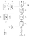
도 1은 일반적인 에너지 저장 장치의 계통 단선도를 나타낸 것이다.1 shows a system breakdown diagram of a general energy storage device.
도 1을 참조하면, 에너지 저장 장치(1)는 운전 모드에 따라 상위 제어기인 에너지 관리 시스템으로부터 목표 값을 받으면, 상기 값을 이용하여 계통(2)이나 부하(3)에 전력을 공급하거나, 충전 동작을 수행하게 된다.1, when the
계통(2)이란 많은 발전소, 변전소, 송배전선 및 부하가 일체로 되어 전력의 발생 및 이용이 이루어지는 시스템이다.The system (2) is a system in which many power plants, substations, transmission and distribution lines and loads are integrated to generate and utilize electric power.
부하(3)는 에너지 저장 장치(1)로부터 전기 에너지를 공급받아 전력을 소모한다.The load (3) receives electric energy from the energy storage device (1) and consumes electric power.
에너지 저장 장치(1)는 발전 장치(도시하지 않음)로부터 전기에너지를 공급받아 충전하고 계통(2) 또는 부하(3)의 전력 수급상황에 따라 충전된 전기 에너지를 방전한다. 구체적으로 계통(2) 또는 부하(3)가 경부하인 경우, 에너지 저장 장치(1)는 발전 장치(도시하지 않음)로부터 유휴 전력을 공급 받아 충전한다. 계통(2) 또는 부하(3)가 과부하인 경우, 에너지 저장 장치(1)는 방전 동작을 수행하여 방전 전력(PG)을 출력하고, 상기 방전 전력(PG)은 계통(2)으로 공급되는 계통 전력(PF)과, 부하(3)로 공급되는 부하 전력(PL)으로 구분되어 상기 계통(2)과 부하(3)로 각각 공급된다.The
그리고, 에너지 저장 장치(1)는 계통에 급격한 부하(3)나 사고 발생 등으로 계통의 주파수나 전압이 변동할 경우에 드룹 제어를 이용하여 계통에 유효 전력 혹은 무효 전력을 공급한다.The
도 2는 일반적인 드룹 제어기의 제어 블록도를 나타낸 것이다.2 shows a control block diagram of a general droop controller.
드룹 제어는, 계통의 주파수 변동 및 전압의 변동에 대해서 에너지 저장 장치가 배터리에 저장된 유효 전력 혹은 무효 전력을 일정 기울기를 두어 제어하는 방법으로, 기본적인 제어 블록도는 도 2에 도시된 바와 같다.The droop control is a method in which the energy storage device controls the active power or the reactive power stored in the battery at a predetermined slope with respect to the frequency variation and the voltage variation of the system, and the basic control block diagram is as shown in FIG.
도 2를 간략하게 설명하면, 드룹 제어기는, 기준 주파수(f0) 값과 계통의 주파수(f)값의 차이 값에 주파수 드룹 계수(1/Rf)를 곱하여 유효전력 드룹 기준 값(Pdroop_ref)을 구한다. 2, the droplet controller obtains the effective power drop reference value Pdroop_ref by multiplying the difference between the reference frequency f0 and the frequency f of the system by the
여기에서, 상기 드룹 제어는, 에너지 저장 장치(1)에서 출력되는 전력에 따라 계통(2)의 주파수를 허용 범위 내에서 유지시키며 전력을 출력하는 방식이며, 시스템 내의 주파수 변동 발생 시에 초기 에너지 저장 장치(1)의 용량과 허용 주파수 변동 범위를 고려하여 유효 전력의 출력을 결정하기 위한 것이다.Here, the droop control is a method of maintaining the frequency of the
이에 따라, 상기 유효전력 드룹 기준 값(Pdroop_ref)는 상기 계통(2)의 주파수가 변동되면, 변동된 주파수 만큼 기설정된 허용 주파수 변동 범위 내에서 상기 유효 전력을 출력 시키기 위한 기준 값이다.Accordingly, the effective power drop reference value Pdroop_ref is a reference value for outputting the active power within a predetermined allowable frequency variation range by the changed frequency when the frequency of the
그리고, 이 유효 전력 드룹 기준 값(Pdroop_ref)은 유효전력 목표값(PDG0)과 합해지고, 이에 의해 얻은 결과 값은 에너지 저장 장치의 동작을 위한 유효전력 기준 값으로 사용된다.The effective power drop reference value (Pdroop_ref) is then added to the effective power target value (PDG0), and the resultant value obtained is used as an active power reference value for operation of the energy storage device.
여기에서, 상기와 같은 에너지 저장 장치는 부하가 증가하면 주파수가 감소하기 때문에 출력이 증가하게 되며, 반대로 부하가 감소하면 주파수가 증가하기 때문에 출력이 감소하게 된다.Here, in the energy storage device as described above, the output increases because the frequency decreases when the load increases. On the contrary, when the load decreases, the frequency increases and the output decreases.
기본적으로 사용되는 주파수 드룹 계수(Rf)와 전압 드룹 계수(Rv)는 아래의 식에 의해 구해진다.The frequency drop coefficient (Rf) and the voltage drop coefficient (Rv), which are basically used, are obtained by the following equations.

그러나, 상기와 같은 종래 기술에 따른 드룹 제어 방식은 에너지 저장 장치의 용량 및 충전 상태를 고려하지 않고, 항상 고정된 주파수 드룹 계수(Rf)만을 사용하고 있다.However, the droop control method according to the related art uses only the fixed frequency droop coefficient Rf without considering the capacity and the charged state of the energy storage device.
이때, 상기와 같이 고정된 주파수 드룹 계수만을 사용하는 경우, 에너지 저장 장치의 운전 모드 및 충전 상태에 따라 과충전 및 과방전이 발생하게 되며, 상기 과충전 및 과방전 발생은 위급한 상황에서 상기 에너지 저장장치의 기동이 불가능하게 하여 신뢰성에 큰 영향을 미친다.In this case, when only the fixed frequency droop coefficient is used as described above, overcharge and overdischarge occur depending on the operation mode and the charge state of the energy storage device, and overcharge and overdischarge occur in an emergency, Making it impossible to start, which greatly affects the reliability.
실시 예에서는, 에너지 저장 장치의 충전 상태에 따라 상기 에너지 저장 장치의 충전 동작 및 방전 동작의 제한 제어(Limit control)을 수행할 수 있도록 한 에너지 저장 장치의 운용 방법을 제공한다.Embodiments provide a method of operating an energy storage device capable of performing a limit control of a charging operation and a discharging operation of the energy storage device according to a charged state of the energy storage device.
또한, 실시 예에서는, 고정된 드룹 계수가 아닌 에너지 저장 장치의 충전 상태에 따라 가변적인 드룹 계수를 적용할 수 있는 에너지 저장 장치의 운용 방법을 제공한다.In addition, the embodiment provides a method of operating an energy storage device that can apply a variable droop coefficient according to a charged state of an energy storage device rather than a fixed droop coefficient.
또한, 실시 예에서는 에너지 저장 장치의 충전 동작 모드에서, 배터리의 충전 상태가 기설정된 제 1 기준 값을 초과하면 충전 속도를 감소시킬 수 있도록 하고, 상기 충전 상태가 상기 제 1 기준 값보다 큰 제 2 기준 값을 초과하면 상기 충전 동작이 중지될 수 있도록 한 에너지 저장 장치의 운용 방법을 제공한다.In addition, in the embodiment, in the charging operation mode of the energy storage device, it is possible to reduce the charging speed when the charging state of the battery exceeds the predetermined first reference value, and when the charging state is lower than the first reference value, And the charging operation can be stopped when the reference value is exceeded.
또한, 실시 예에서는 에너지 저장 장치의 방전 동작 모드에서, 배터리의 충전 상태가 기설정된 제 3 기준 값 미만으로 감소하면 방전 속도를 감소시킬 수 있도록 하고, 상기 방전 상태가 상기 제 3 기준 값보다 작은 제 4 기준 값 미만으로 감소하면 상기 방전 동작이 중지될 수 있도록 한 에너지 저장 장치의 운용 방법을 제공한다.Further, in the embodiment, in the discharge operation mode of the energy storage device, when the state of charge of the battery is reduced to less than a predetermined third reference value, the discharge speed may be reduced, and when the discharge state is smaller than the
제안되는 실시 예에서 이루고자 하는 기술적 과제들은 이상에서 언급한 기술적 과제들로 제한되지 않으며, 언급되지 않은 또 다른 기술적 과제들은 아래의 기재로부터 제안되는 실시 예가 속하는 기술분야에서 통상의 지식을 가진 자에게 명확하게 이해될 수 있을 것이다.It is to be understood that the technical objectives to be achieved by the embodiments are not limited to the technical matters mentioned above and that other technical subjects not mentioned are apparent to those skilled in the art to which the embodiments proposed from the following description belong, It can be understood.
실시 예에 따른 에너지 저장 장치는 전력을 공급하는 전력 공급부; 충전 모드에서 상기 전력 공급부를 통해 공급되는 전력에 의해 충전되고, 방전 모드에서 기저장한 전력을 방전하는 에너지 저장부; 상기 충전 모드에서 상기 전력 공급부를 통해 공급되는 전력을 변환하여 상기 에너지 저장부에 공급하고, 상기 방전 모드에서 상기 에너지 저장부에 저장된 전력을 변환하여 외부로 출력하는 전력 변환부; 및 상기 에너지 저장부의 운전 모드에 따른 충전 동작 또는 방전 동작이 수행되도록 상기 전력 변환부에 스위칭 신호를 출력하는 시스템 제어부를 포함하며, 상기 시스템 제어부는, 상기 에너지 저장부의 운전 모드 및 충전 상태(SOC:State Of Charge)를 확인하고, 상기 확인한 운전 모드 및 충전 상태에 따라 서로 다른 게인 값을 적용하여 상기 에너지 저장부의 목표 값을 설정하고, 상기 설정된 목표 값에 대응하는 스위칭 신호를 출력하는 드룹 제어부를 포함한다.An energy storage device according to an embodiment includes a power supply unit for supplying power; An energy storage unit that is charged by the power supplied through the power supply unit in the charge mode and discharges the stored power in the discharge mode; A power conversion unit for converting power supplied through the power supply unit in the charge mode and supplying the converted power to the energy storage unit, and converting the power stored in the energy storage unit in the discharge mode to output the power to the outside; And a system controller for outputting a switching signal to the power conversion unit such that a charging operation or a discharging operation is performed according to an operation mode of the energy storage unit, wherein the system control unit controls the operation mode of the energy storage unit, State of charge, and sets a target value of the energy storage unit by applying different gain values according to the determined operation mode and charging state, and outputs a switching signal corresponding to the set target value do.
또한, 상기 에너지 저장부는, 상기 충전 모드에서, 제 1 기울기에 따른 충전 속도에 의해 충전이 이루어지는 충전 구동 영역과, 상기 충전 모드에서, 상기 제 1 기울기 보다 낮은 제 2 기울기에 따른 충전 속도에 의해 충전이 이루어지는 충전 데드 밴드 영역을 포함한다.The energy storage unit may further include a charging drive region in which charging is performed by a charging rate corresponding to a first slope in the charging mode and a charging driving region in which the charging is performed by a charging rate according to a second slope lower than the first slope in the charging mode. And a charge dead band region in which the charge dead band region is formed.
또한, 상기 에너지 저장부는, 상기 방전 모드에서, 제 1 기울기에 따른 방전 속도에 의해 방전이 이루어지는 방전 구동 영역과, 상기 방전 모드에서, 상기 제 1 기울기 보다 낮은 제 2 기울기에 따른 방전 속도에 의해 방전이 이루어지는 방전 데드 밴드 영역을 포함한다.The energy storage unit may further include a discharge drive region in which the discharge is performed at a discharge rate corresponding to a first slope in the discharge mode and a discharge drive region in which the discharge is performed at a discharge rate according to a second slope lower than the first slope, And a discharge dead band region in which discharge is performed.
또한, 상기 드룹 제어부는, 상기 에너지 저장부의 운전 모드가 충전 모드이고, 상기 충전 상태가 제 1 기준 값 미만이면, 제 1 게인 값을 적용하여 상기 에너지 저장부의 목표 값을 설정하고, 상기 충전 상태가 제 1 기준 값보다 크고 제 2 기준 값보다 작으면, 상기 제 1 게인 값보다 작은 제 2 게인 값을 적용하여 상기 에너지 저장부의 목표 값을 설정한다.The droop control unit sets a target value of the energy storage unit by applying a first gain value when the operation mode of the energy storage unit is a charge mode and the charge state is less than a first reference value, A second gain value smaller than the first gain value is applied to set the target value of the energy storage unit when the first gain value is greater than the first reference value and smaller than the second reference value.
또한, 상기 제 1 게인 값은 1이고, 상기 제 2 게인 값은 0보다 크고, 1보다 작은 값이다.The first gain value is 1, and the second gain value is larger than 0 and smaller than 1.
또한, 상기 드룹 제어부는, 상기 에너지 저장부의 운전 모드가 충전 모드이고, 상기 충전 상태가 제 2 기준 값보다 크면, 상기 제 2 게인 값보다 작은 제 3 게인 값을 적용하여 상기 에너지 저장부의 목표 값을 설정한다.If the operation mode of the energy storing unit is the charge mode and the charge state is greater than the second reference value, the droop control unit applies a third gain value smaller than the second gain value to the target value of the energy storage unit Setting.
또한, 상기 제 3 게인 값은 0이고, 상기 제 3 게인 값에 의해 설정된 에너지 저장부의 목표 값은 0이다.Also, the third gain value is 0, and the target value of the energy storage unit set by the third gain value is zero.
또한, 상기 드룹 제어부는, 상기 에너지 저장부의 운전 모드가 방전 모드이고, 상기 충전 상태가 제 3 기준 값보다 크면, 제 1 게인 값을 적용하여 상기 에너지 저장부의 목표 값을 설정하고, 상기 충전 상태가 제 3 기준 값보다 작고 제 4 기준 값보다 크면, 상기 제 1 게인 값보다 작은 제 2 게인 값을 적용하여 상기 에너지 저장부의 목표 값을 설정한다.The droop control unit sets a target value of the energy storage unit by applying a first gain value when the operation mode of the energy storage unit is a discharge mode and the charge state is greater than a third reference value, A second gain value smaller than the first gain value is applied to set the target value of the energy storage unit if the second gain value is smaller than the third reference value and larger than the fourth reference value.
또한, 상기 드룹 제어부는, 상기 에너지 저장부의 운전 모드가 방전 모드이고, 상기 충전 상태가 제 4 기준 값보다 작으면, 상기 제 2 게인 값보다 작은 제 3 게인 값을 적용하여 상기 에너지 저장부의 목표 값을 설정하며, 상기 제 3 게인 값은 0이고, 상기 제 3 게인 값에 의해 설정된 에너지 저장부의 목표 값은 0이다.In addition, if the operation mode of the energy storage unit is in the discharge mode and the charge state is less than the fourth reference value, the droop control unit applies a third gain value smaller than the second gain value, The third gain value is 0, and the target value of the energy storage unit set by the third gain value is zero.
또한, 상기 에너지 저장부의 목표 값은, 계통의 주파수 및 주파수 드롭 계수에 따른 유효 전력의 목표 값이다.The target value of the energy storage unit is a target value of the active power according to the frequency and the frequency drop coefficient of the system.
본 발명에 따른 실시 예에 의하면, 에너지 저장 장치의 충전 동작 모드에서, 배터리의 충전 상태가 기설정된 제 1 기준 값을 초과하면 게인 값 변경을 통해 충전 속도를 감소시키고, 상기 충전 상태가 상기 제 1 기준 값보다 큰 제 2 기준 값을 초과하면 상기 변경된 게인 값의 재변경을 통해 상기 충전 동작이 중지될 수 있도록 함으로써, 상기 배터리가 과충전되는 것을 사전에 방지하여 배터리를 보호하고 안정적으로 운용될 수 있도록 한다.According to the embodiment of the present invention, in the charge operation mode of the energy storage device, when the charge state of the battery exceeds the predetermined first reference value, the charge rate is decreased by changing the gain value, The charging operation can be stopped by re-changing the changed gain value if the second reference value is larger than the reference value so that the battery is prevented from overcharging in advance to protect the battery and operate stably do.
또한, 본 발명에 따른 실시 예에 의하면, 에너지 저장 장치의 방전 동작 모드에서, 배터리의 충전 상태가 기설정된 제 3 기준 값 미만으로 감소하면 게인 값의 변경을 통해 방전 속도를 감소시킬 수 있도록 하고, 상기 방전 상태가 상기 제 3 기준 값보다 작은 제 4 기준 값 미만으로 감소하면 상기 변경된 게인 값의 재변경을 통해 상기 방전 동작이 중지될 수 있도록 함으로써, 상기 배터리가 과방전되는 것을 사전에 방지하여 배터리를 보호하고 안정적으로 운용될 수 있도록 한다.According to the embodiment of the present invention, in the discharge operation mode of the energy storage device, when the state of charge of the battery is decreased to a value less than a predetermined third reference value, the discharge speed can be reduced by changing the gain value, If the discharge state is reduced to a value less than a fourth reference value smaller than the third reference value, the discharge operation can be stopped by re-changing the changed gain value, thereby preventing the battery from being overdischarged in advance, So that it can be operated stably.
도 1은 일반적인 에너지 저장 장치의 계통 단선도를 나타낸 것이다.
도 2는 일반적인 드룹 제어기의 제어 블록도를 나타낸 것이다.
도 3은 본 발명의 일 실시예에 따른 에너지 저장 시스템의 블록도이다.
도 4는 도 3에 도시된 드룹 제어부(111)의 상세 블록도이다.
도 5는 종래 기술에 따른 에너지 저장부(113)의 충전 속도 및 방전 속도를 보여주는 도면이다.
도 6은 본 발명의 실시 예에 따른 에너지 저장부(113)의 충전 속도 및 방전 속도를 보여준다.
도 7은 본 발명의 실시 예에 따른 에너지 저장 장치에서, 충전 동작 시의 운용 방법을 단계별로 설명하기 위한 흐름도이다.
도 8은 본 발명의 실시 예에 따른 에너지 저장 장치에서, 방전 동작 시의 운용 방법을 단계별로 설명하기 위한 흐름도이다.1 shows a system breakdown diagram of a general energy storage device.
2 shows a control block diagram of a general droop controller.
3 is a block diagram of an energy storage system in accordance with an embodiment of the present invention.
4 is a detailed block diagram of the
FIG. 5 is a view showing a charging speed and a discharging speed of the
6 shows the charge rate and discharge rate of the
FIG. 7 is a flowchart for explaining a step-by-step operation method in the charging operation in the energy storage device according to the embodiment of the present invention.
FIG. 8 is a flowchart for explaining a step-by-step operation method in a discharge operation in the energy storage device according to the embodiment of the present invention.
본 발명의 이점 및 특징, 그리고 그것들을 달성하는 방법은 첨부되는 도면과 함께 상세하게 후술되어 있는 실시 예들을 참조하면 명확해질 것이다. 그러나 본 발명은 이하에서 개시되는 실시 예들에 한정되는 것이 아니라 서로 다른 다양한 형태로 구현될 수 있으며, 단지 본 실시 예들은 본 발명의 개시가 완전하도록 하고, 본 발명이 속하는 기술분야에서 통상의 지식을 가진 자에게 발명의 범주를 완전하게 알려주기 위해 제공되는 것이며, 본 발명은 청구항의 범주에 의해 정의될 뿐이다. 명세서 전체에 걸쳐 동일 참조 부호는 동일 구성 요소를 지칭한다.BRIEF DESCRIPTION OF THE DRAWINGS The advantages and features of the present invention and the manner of achieving them will become apparent with reference to the embodiments described in detail below with reference to the accompanying drawings. The present invention may, however, be embodied in many different forms and should not be construed as being limited to the embodiments set forth herein. Rather, these embodiments are provided so that this disclosure will be thorough and complete, and will fully convey the concept of the invention to those skilled in the art. Is provided to fully convey the scope of the invention to those skilled in the art, and the invention is only defined by the scope of the claims. Like reference numerals refer to like elements throughout the specification.
본 발명의 실시 예들을 설명함에 있어서 공지 기능 또는 구성에 대한 구체적인 설명이 본 발명의 요지를 불필요하게 흐릴 수 있다고 판단되는 경우에는 그 상세한 설명을 생략할 것이다. 그리고 후술되는 용어들은 본 발명의 실시 예에서의 기능을 고려하여 정의된 용어들로서 이는 사용자, 운용자의 의도 또는 관례 등에 따라 달라질 수 있다. 그러므로 그 정의는 본 명세서 전반에 걸친 내용을 토대로 내려져야 할 것이다.In the following description of the present invention, a detailed description of known functions and configurations incorporated herein will be omitted when it may make the subject matter of the present invention rather unclear. The following terms are defined in consideration of the functions in the embodiments of the present invention, which may vary depending on the intention of the user, the intention or the custom of the operator. Therefore, the definition should be based on the contents throughout this specification.
첨부된 도면의 각 블록과 흐름도의 각 단계의 조합들은 컴퓨터 프로그램 인스트럭션들에 의해 수행될 수도 있다. 이들 컴퓨터 프로그램 인스트럭션들은 범용 컴퓨터, 특수용 컴퓨터 또는 기타 프로그램 가능한 데이터 프로세싱 장비의 프로세서에 탑재될 수 있으므로, 컴퓨터 또는 기타 프로그램 가능한 데이터 프로세싱 장비의 프로세서를 통해 수행되는 그 인스트럭션들이 도면의 각 블록 또는 흐름도의 각 단계에서 설명된 기능들을 수행하는 수단을 생성하게 된다. 이들 컴퓨터 프로그램 인스트럭션들은 특정 방식으로 기능을 구현하기 위해 컴퓨터 또는 기타 프로그램 가능한 데이터 프로세싱 장비를 지향할 수 있는 컴퓨터 이용 가능 또는 컴퓨터 판독 가능 메모리에 저장되는 것도 가능하므로, 그 컴퓨터 이용가능 또는 컴퓨터 판독 가능 메모리에 저장된 인스트럭션들은 도면의 각 블록 또는 흐름도 각 단계에서 설명된 기능을 수행하는 인스트럭션 수단을 내포하는 제조 품목을 생산하는 것도 가능하다. 컴퓨터 프로그램 인스트럭션들은 컴퓨터 또는 기타 프로그램 가능한 데이터 프로세싱 장비 상에 탑재되는 것도 가능하므로, 컴퓨터 또는 기타 프로그램 가능한 데이터 프로세싱 장비 상에서 일련의 동작 단계들이 수행되어 컴퓨터로 실행되는 프로세스를 생성해서 컴퓨터 또는 기타 프로그램 가능한 데이터 프로세싱 장비를 수행하는 인스트럭션들은 도면의 각 블록 및 흐름도의 각 단계에서 설명된 기능들을 실행하기 위한 단계들을 제공하는 것도 가능하다.Combinations of the steps of each block and flowchart in the accompanying drawings may be performed by computer program instructions. These computer program instructions may be embedded in a processor of a general purpose computer, special purpose computer, or other programmable data processing apparatus so that the instructions, which may be executed by a processor of a computer or other programmable data processing apparatus, Thereby creating means for performing the functions described in the step. These computer program instructions may also be stored in a computer usable or computer readable memory capable of directing a computer or other programmable data processing apparatus to implement the functionality in a particular manner so that the computer usable or computer readable memory It is also possible to produce manufacturing items that contain instruction means that perform the functions described in each block or flowchart illustration in each step of the drawings. Computer program instructions may also be stored on a computer or other programmable data processing equipment so that a series of operating steps may be performed on a computer or other programmable data processing equipment to create a computer- It is also possible for the instructions to perform the processing equipment to provide steps for executing the functions described in each block and flowchart of the drawings.
또한, 각 블록 또는 각 단계는 특정된 논리적 기능(들)을 실행하기 위한 하나 이상의 실행 가능한 인스트럭션들을 포함하는 모듈, 세그먼트 또는 코드의 일부를 나타낼 수 있다. 또, 몇 가지 대체 실시 예들에서는 블록들 또는 단계들에서 언급된 기능들이 순서를 벗어나서 발생하는 것도 가능함을 주목해야 한다. 예컨대, 잇달아 도시되어 있는 두 개의 블록들 또는 단계들은 사실 실질적으로 동시에 수행되는 것도 가능하고 또는 그 블록들 또는 단계들이 때때로 해당하는 기능에 따라 역순으로 수행되는 것도 가능하다.Also, each block or each step may represent a module, segment, or portion of code that includes one or more executable instructions for executing the specified logical function (s). It should also be noted that in some alternative embodiments, the functions mentioned in the blocks or steps may occur out of order. For example, two blocks or steps shown in succession may in fact be performed substantially concurrently, or the blocks or steps may sometimes be performed in reverse order according to the corresponding function.
도 3은 본 발명의 일 실시예에 따른 에너지 저장 시스템의 블록도이다.3 is a block diagram of an energy storage system in accordance with an embodiment of the present invention.
본 발명의 일 실시예에 따른 에너지 저장 시스템(100)은 발전 장치(101), 직류/교류 컨버터(103), 교류 필터(105), 교류/교류 컨버터(107), 계통(109), 드룹 제어부(111), 에너지 저장부(113), 시스템 제어부(115), 부하(117) 및 직류/직류 컨버터(121)를 포함한다.The
발전 장치(101)는 전기 에너지를 생산한다. 발전 장치가 태양광 발전 장치인 경우, 발전 장치(101)는 태양 전지 어레이일 수 있다. 태양 전지 어레이는 복수의 태양전지 모듈을 결합한 것이다. 태양전지 모듈은 복수의 태양전지 셀을 직렬 또는 병렬로 연결하여 태양 에너지를 전기 에너지로 변환하여 소정의 전압과 전류를 발생키는 장치이다. 따라서 태양전지 어레이는 태양 에너지를 흡수하여 전기 에너지로 변환한다. 또한 발전 시스템이 풍력 발전 시스템인 경우, 발전 장치(101)는 풍력 에너지를 전기 에너지를 변환하는 팬일 수 있다. 다만, 앞서 기재한 바와 같이 에너지 저장 시스템(100)은 발전 장치(101) 없이 에너지 저장부(113)에 저장된 에너지만을 통하여 전력을 공급할 수 있다. 이 경우 에너지 저장 시스템(100)은 발전 장치(101)를 포함하지 않을 수 있다.The
직류/교류 컨버터(103)는 직류 전력을 교류 전력으로 컨버팅한다. 발전 장치(101)가 공급한 직류 전력 또는 에너지 저장부(113)가 방전한 직류 전력을 교류 전력으로 컨버팅한다.The DC /
교류 필터(105)는 교류 전력으로 컨버팅된 전력의 노이즈를 필터링한다. 구체적인 실시예에서 교류 필터(105)는 생략될 수 있다.The
교류/교류 컨버터(107)는 교류 전력을 계통(109) 또는 부하(117)에 공급할 수 있도록 노이즈가 필터링된 교류 전력의 전압의 크기를 컨버팅하여 전력을 계통(109) 또는 독립된 부하에 공급한다. 구체적인 실시예에 따라서 교류/교류 컨버터(107)는 생략될 수 있다.The AC /
계통(109)이란 많은 발전소, 변전소, 송배전선 및 부하가 일체로 되어 전력의 발생 및 이용이 이루어지는 시스템이다.The
부하(117)는 발전 시스템으로부터 전기 에너지를 공급받아 전력을 소모한다. 에너지 저장부(113)는 발전 장치(101)로부터 전기에너지를 공급받아 충전하고 계통(109) 또는 부하(117)의 전력 수급상황에 따라 충전된 전기 에너지를 방전한다. 구체적으로 계통(109) 또는 부하(117)가 경부하인 경우, 에너지 저장부(113)는 발전 장치(101)로부터 유휴 전력을 공급 받아 충전한다. 계통(109) 또는 부하(117)가 과부하인 경우, 에너지 저장부(113)는 충전된 전력을 방전하여 계통(109) 또는 부하(117)에 전력을 공급한다. 계통(109) 또는 부하(117)의 전력 수급 상황은 시간대별로 큰 차이를 가질 수 있다. 따라서 에너지 저장 시스템(100)이 발전 장치(101)가 공급하는 전력을 계통(109) 또는 부하(117)의 전력 수급상황에 대한 고려 없이 일률적으로 공급하는 것은 비효율적이다. 그러므로 에너지 저장 시스템(100)은 에너지 저장부(113)를 사용하여 계통(109) 또는 부하(117)의 전력 수급상황에 따라 전력 공급의 양을 조절 한다. 이를 통해 에너지 저장 시스템(100)은 계통(109) 또는 부하(117)에 효율적으로 전력을 공급할 수 있다.The
직류/직류 컨버터(121)는 에너지 저장부(113)가 공급하거나 공급받는 직류 전력의 크기를 컨버팅한다. 구체적인 실시예에 따라서는 직류/직류 컨버터(121)는 생략될 수 있다.The DC /
시스템 제어부(115)는 직류/교류 컨버터(103) 및 교류/교류 컨버터(107)의 동작을 제어한다. 또한 시스템 제어부(115)는 에너지 저장부(113)의 충전과 방전을 제어하는 드룹 제어부(111)를 포함할 수 있다. 드룹 제어부(111)는 에너지 저장부(113)의 충전 및 방전을 제어한다. 계통(109) 또는 부하(117)가 과부하인 경우, 드룹 제어부(111)는 배터리 에너지 저장 시스템(113)이 전력을 공급하여 계통(109) 또는 부하(117)에 전력을 전달하게 제어한다. 계통(109) 또는 부하(117)가 경부하인 경우, 드룹 제어부(111)는 외부의 전력 공급원 또는 발전 장치(101)가 전력을 공급하여 에너지 저장부(113)에 전달하게 제어한다.The
한편, 드룹 제어부(111)는 시스템 주파수와 측정된 주파수의 변화량과 미리 설정된 드룹 계수에 의해 상기 에너지 저장부(113)의 입력 값 및 출력 값을 각각 결정한다.On the other hand, the
이때, 드룹 제어부(111)는 에너지 저장부(113)의 운전 모드 및 상기 에너지 저장부(113)의 충전 상태(SOC:State Of Charge)에 따라 상기 드룹 계수에 의해 결정된 입력 값 및 출력 값이 특정 게인 값을 적용한다.At this time, the
상기 에너지 저장부(113)의 운전 모드는 충전 모드 및 방전 모드로 구분될 수 있다.The operation mode of the
충전 모드는 발전량이 부하량보다 많은 경우이며, 이 모드에서는 상기 발전 장치(101)에서 발전된 전력에 의해 상기 에너지 저장부(113)의 충전이 이루어진다.In this mode, the
또한, 방전 모드는 발전량이 부하량보다 적은 경우이며, 이 모드에서는 상기 에너지 저장부(113)의 방전에 의해 상기 에너지 저장부(113)에 저장된 전력이 계통으로 출력된다.Also, in the discharge mode, the power generation amount is smaller than the load amount. In this mode, the power stored in the
그리고, 드룹 제어부(111)는 상기와 같은 운전 모드 및 실시간으로 측정되는 상기 에너지 저장부(113)의 충전 상태에 따라 서로 다른 게인 값의 적용을 통한 드룹 제어 방식을 통해 상기 에너지 저장부(113)의 운전 모드에 따른 충전 동작 또는 방전 동작을 제어한다.Then, the
이하에서는, 상기 드룹 제어부(111)의 동작에 대해 보다 구체적으로 설명하기로 한다.Hereinafter, the operation of the
도 4는 도 3에 도시된 드룹 제어부(111)의 상세 블록도이다.4 is a detailed block diagram of the
도 4를 참조하면, 드룹 제어부(111)는 기준 전압 값(Vref)과 계통의 현재 전압 값(V)을 확인하고, 상기 확인한 기준 전압 값(Vref)과 현재 전압 값(V)의 전압 차이값을 구하는 전압 차이 값 출력부(201)를 포함한다.4, the
전압 차이 값 출력부(201)는 상기 설명한 바와 같이, 기준 전압 값(Vref)과 현재 전압 값(V)의 차이 값을 계산하여 출력한다.The voltage difference
또한, 드룹 제어부(111)는 상기 전압 차이 값이 구해지면, 상기 구해진 전압 차이 값에 전압 드룹 계수(1/Rv)를 곱하여, 무효 전력의 드룹 기준 값을 출력하는 제 1 드룹 기준 값 출력부(202)를 포함한다.In addition, when the voltage difference value is obtained, the
여기에서, 전력은 무효 전력과 유효 전력으로 구분되는데, 상기 유효 전력은 계통의 주파수와 밀접한 관계가 있고, 무효 전력은 계통의 전압과 밀접한 관계가 있다. 이에 따라, 상기 유효 전력은 계통의 주파수에 의해 조정되고, 상기 유효 전력은 계통이 전압에 의해 조정된다.Here, power is divided into reactive power and active power. The active power is closely related to the frequency of the system, and the reactive power is closely related to the voltage of the system. Accordingly, the active power is adjusted by the frequency of the system, and the active power is adjusted by the system.
여기에서, 상기 전압 드룹 계수는 아래와 같은 식에 의해 구해질 수 있다.Here, the voltage droop coefficient can be obtained by the following equation.
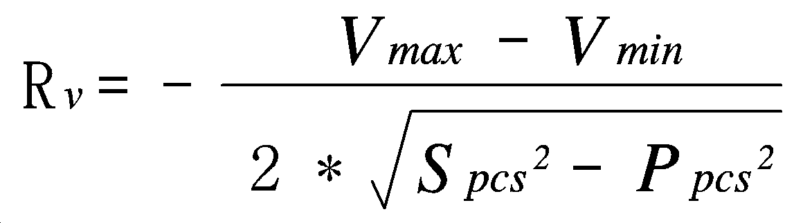
상기 제 1 드룹 기준 값 출력부(202)는 상기 식을 이용하여 전압 드룹 계수를 구하고, 그에 따라 상기 전압 차이 값 출력부(201)의 출력 값에 상기 전압 드룹 계수를 곱하여, 무효 전력의 드룹 기준 값을 출력한다.The first droop reference
또한, 드룹 제어부(111)는 상기 무효 전력의 드룹 기준 값이 구해지면, 목표로 하는 무효 전력 지령 값(QDG)에 상기 드룹 기준 값을 더하여 무효 전력 기준 값(Qref)을 구하는 무효 전력 기준 값 출력부(203)를 더 포함한다.When the droop reference value of the reactive power is obtained, the
또한, 상기 드룹 제어부(111)는상기 무효 전력 기준 값(Qref)이 구해지면, 상기 무효 전력 기준 값(Qref)과 현재 무효 전력 값의 차이 값을 구하고, 그에 따라 상기 구해진 차이 값을 출력하는 제 1 차이 값 출력부(204)를 더 포함한다.When the reactive power reference value Qref is obtained, the
이어서, 상기 드룹 제어부(111)는 상기 제 1 차이 값 출력부(204)에 의해 차이 값이 출력되면, 상기 출력되는 차이 값에 대하여 비례 적분 제어를 통해 제 1 출력 값을 생성하는 제 1 비례적분 제어기(205)를 더 포함한다.Then, when the difference value is outputted by the first difference
또한, 드룹 제어부(111)는 기준 주파수 값(fref)과 계통의 현재 주파수 값(f)을 확인하고, 상기 확인한 기준 주파수 값(fref)과 현재 주파수 값(f)의 주파수 차이값을 구하는 주파수 차이 값 출력부(206)를 포함한다.The
주파수 차이 값 출력부(206)는 상기 설명한 바와 같이, 기준 주파수 값(fref)과 현재 주파수 값(f)의 차이 값을 계산하여 출력한다.The frequency difference
또한, 드룹 제어부(111)는 상기 주파수 차이 값이 구해지면, 상기 구해진 주파수 차이 값에 주파수 드룹 계수(1/Rf)를 곱하여, 유효 전력의 드룹 기준 값을 출력하는 제 2 드룹 기준 값 출력부(207)를 포함한다.Further, when the frequency difference value is obtained, the
여기에서, 상기 주파수 드룹 계수는 아래와 같은 식에 의해 구해질 수 있다.Here, the frequency droop coefficient can be obtained by the following equation.

여기에서, 상기 pcs는 전력 변환부를 의미한다.Here, pcs denotes a power conversion unit.
상기 제 2 드룹 기준 값 출력부(207)는 상기 식을 이용하여 주파수 드룹 계수를 구하고, 그에 따라 상기 주파수 차이 값 출력부(206)의 출력 값에 상기 주파수 드룹 계수를 곱하여, 유효 전력의 드룹 기준 값을 출력한다.The second droop reference
상기 유효 전력의 드룹 기준 값이 결정되면, 드룹 제어부(111)는 상위 제어기로부터 제공된 유효 전력 지령 값(PDG)에 상기 유효 전력의 드룹 기준 값을 더하여 유효 전력 기준 값(Pref)을 구하는 유효 전력 기준 값 출력부(208)를 더 포함한다.If the droop reference value of the active power is determined, the
또한, 드룹 제어부(111)는 상기 유효 전력의 기준 값(유효 전력의 목표 값)이 구해지면, 에너지 저장부(113)의 운전 모드 및 충전 상태에 따라 게인 값을 결정하고, 상기 결정한 게인 값을 적용하여 상기 충전 상태에 따라 에너지 저장부(113)의 제한 제어를 수행하는 제한 제어부(209)를 포함한다.When the reference value of the active power (the target value of the active power) is obtained, the
제한 제어부(209)는 상기 게인 값을 결정하기 위하여, 우선적으로 상기 에너지 저장부(113)의 운전 모드를 확인한다.The
즉, 제한 제어부(209)는 상기 드룹 제어부(111)에 의해 수행되는 드룹 제어가 방전 동작을 위한 드룹 제어인지, 아니면 충전 동작을 위한 드룹 제어인지를 확인한다.That is, the
이어서, 상기 제한 제어부(209)는 상기 운전 모드가 확인되면, 상기 확인한 운전 모드에 따라 상기 에너지 저장부(113)의 충전 상태를 확인한다.Then, when the operation mode is confirmed, the
여기에서, 상기 제한 제어부(209)는 상기 운전 모드에 따라 서로 다른 기준 값을 적용하여 상기 에너지 저장부(113)의 충전 상태가 제 1 상태, 제 2 상태 및 제 3 상태 중 어느 상태인지를 확인한다.Here, the
우선적으로, 상기 에너지 저장부(113)가 충전 모드로 동작하는 상황에서의 게인 값 결정 과정에 대해 설명하기로 한다.First, a process of determining a gain value in a state where the
이하에는, 에너지 저장부(113)의 충전 상태(SOC)에 대한 복수의 기준 값이 설정되어 있다.Hereinafter, a plurality of reference values for the state of charge (SOC) of the
이때, 상기 복수의 기준 값은, 상기 충전 상태(SOC)에 따른 에너지 저장부(113)의 충전 동작 및 방전 동작에 대한 다양한 실험을 통해 최적의 값을 선정하여 결정할 수 있으며, 이와 다르게 사용자에 의해 임의의 값으로 설정될 수 있다.At this time, the plurality of reference values can be determined by selecting optimal values through various experiments on the charging operation and the discharging operation of the
상기 제한 제어부(209)는 상기 에너지 저장부(113)가 충전 모드로 동작하면, 상기 에너지 저장부(113)의 충전 상태가 제 1 기준 값보다 낮은지 여부를 판단한다. The
여기에서, 상기 제 1 기준 값은 SOC=85%일 수 있다. 이와 다르게 상기 제 1 기준 값은 사용자가 임의로 설정할 수 있다.Here, the first reference value may be SOC = 85%. Alternatively, the first reference value may be set by the user.
즉, 제한 제어부(209)는 상기 에너지 저장부(113)의 충전 상태가 85%보다 낮은지 여부를 판단한다.That is, the
그리고, 제한 제어부(209)는 상기 에너지 저장부(113)의 충전 상태가 85%보다 낮으면, 제 1 게인 값을 적용하여 상기 유효 전력의 기준 값(유효 전력의 목표 값)을 변경한다.If the charge state of the
여기에서, 상기 제 1 게인 값을 1일 수 있다. 이와 다르게, 상기 제 1 기준 값은 사용자가 임의로 설정할 수 있다. Here, the first gain value may be one. Alternatively, the first reference value may be set by the user.
즉, 제한 제어부(209)는 에너지 저장부(113)의 충전 상태에 따라 복수의 게인 값 중 어느 하나의 게인 값을 적용하여 유효 전력의 기준 값을 변경한다. 이때, 상기 복수의 게인 값은, 상기 유효 전력의 기준 값을 변경하기 위한 값이다. 보다 구체적으로, 상기 복수의 게인 값은 에너지 관리 시스템과 같은 상위 제어기로부터 공급된 목표 값에 따라 결정된 상기 유효 전력의 기준 값을 그대로 유지시키기 위한 제 1 게인 값과, 상기 결정된 유효 전력의 기준 값을 0보다 큰 값으로 감소시키기 위한 제 2 게인 값과, 상기 결정된 유효 전력의 기준 값을 0으로 감소시키기 위한 제 3 게인 값을 포함한다.That is, the
이때, 아래에서는 상기 제 2 게인 값이 하나의 값으로만 고정되어 있다고 설정하나, 상기 충전 상태를 복수의 단계로 구분하고, 그에 따라 상기 복수의 단계에 따른 충전 상태 별로 상기 유효 전력의 기준 값을 감소시키기 위한 복수의 제 2 게인 값을 각각 설정할 수도 있다.In this case, it is assumed that the second gain value is fixed to only one value below, but the charge state is divided into a plurality of steps, and the reference value of the active power is determined for each charge state according to the plurality of steps It is also possible to set a plurality of second gain values for reducing the gain.
여기에서, 상기 제 1 게인 값은 1일 수 있다. 즉, 상기 제 1 게인 값은 상기 결정된 유효 전력의 기준 값을 그대로 유지시키기 위한 값이며, 상기 결정된 유효 전력의 기준 값에 곱해지는 값이다. 따라서, 상기 제 1 게인 값은 상기 유효 전력의 기준 값을 그대로 유지시키기 위해 '1'로 설정될 수 있다.즉, 상기 제한 제어부(209)는 상기 에너지 저장부(113)가 충전 모드로 동작하고, 상기 에너지 저장부(113)의 충전 상태가 85%보다 낮으면, 상기 주파수 드룹 계수에 의해 구해진 상기 유효 전력의 기준 값(유효 전력의 목표 값)을 그대로 출력한다.Here, the first gain value may be one. That is, the first gain value is a value for maintaining the reference value of the determined active power, and is a value multiplied by the reference value of the determined active power. Accordingly, the first gain value may be set to '1' to maintain the reference value of the active power as it is. That is, the
또한, 제한 제어부(209)는 상기 에너지 저장부(113)의 충전 상태가 제 1 기준 값보다 높으면, 상기 충전 상태가 제 1 기준 값과 제 2 기준 값 사이에 있는지 여부를 판단한다.If the charging state of the
여기에서, 상기 제 2 기준 값은 SOC=90%일 수 있다. 이와 다르게, 상기 제 2 기준 값은 사용자가 임의로 설정할 수 있다.Here, the second reference value may be SOC = 90%. Alternatively, the second reference value may be set by the user.
즉, 제한 제어부(209)는 상기 에너지 저장부(113)의 충전 상태가 85%와 90% 사이에 존재하는지 여부를 판단한다.That is, the
그리고, 제한 제어부(209)는 상기 에너지 저장부(113)가 충전 모드로 동작하고, 상기 에너지 저장부(113)의 충전 상태가 85%에서 90% 사이에 존재하면, 제 2 게인 값을 적용하여 상기 유효 전력의 기준 값(유효 전력의 목표 값)을 변경한다.If the
여기에서, 상기 제 2 게인 게인 값은 0과 1 사이의 값일 수 있다. 즉, 상기 제 2 게인 값은 상기 결정된 유효 전력의 기준 값을 감소시키기 위한 값이며, 상기 결정된 유효 전력의 기준 값에 곱해지는 값이다. 따라서, 상기 제 2 게인 값은 상기 유효 전력의 기준 값을 감소시키기 위해 1보다는 작으면서 0보다는 큰 어느 하나의 값으로 설정될 수 있다.Here, the second gain gain value may be a value between 0 and 1. That is, the second gain value is a value for decreasing the reference value of the determined active power, and is a value multiplied by the reference value of the determined active power. Therefore, the second gain value may be set to any value smaller than 1 but larger than 0 in order to reduce the reference value of the active power.
다시 말해서, 상기 제 2 게인 값에 의해 조정된 유효 전력의 목표 값은 상기 제 1 게인 값에 의해 구해진 유효 전력의 목표 값보다 낮은 값이다.In other words, the target value of the active power adjusted by the second gain value is a value lower than the target value of the active power obtained by the first gain value.
바람직하게, 상기 제 2 게인 값은 0.5일 수 있다.Preferably, the second gain value may be 0.5.
즉, 제한 제어부(209)는 상기 에너지 저장부(113)가 충전 모드로 동작하고, 상기 에너지 저장부(113)의 충전 상태가 85%에서 90% 사이에 존재하면, 상기 제 2 게인 값을 적용하여 상기 에너지 저장부(113)의 충전 속도가 감소되도록 한다.That is, when the
또한, 제한 제어부(209)는 상기 에너지 저장부(113)의 충전 상태가 제 2 기준 값을 초과하였는지를 확인한다.Also, the
즉, 제한 제어부(209)는 상기 에너지 저장부(113)의 충전 상태가 90%를 초과하였는지 여부를 판단한다.That is, the
그리고, 제한 제어부(209)는 상기 에너지 저장부(113)가 충전 모드로 동작하고, 상기 에너지 저장부(113)의 충전 상태가 90%를 초과하였다면, 제 3 게인 값을 적용하여 상기 유효 전력의 기준 값(유효 전력의 목표 값)을 변경한다.If the
여기에서, 상기 제 3 게인 게인 값은 0일 수 있다. 즉, 상기 제 3 게인 값은 상기 결정된 유효 전력의 기준 값을 0으로 설정하기 위한 값이며, 상기 결정된 유효 전력의 기준 값에 곱해지는 값이다. 따라서, 상기 제 3 게인 값은 상기 유효 전력의 기준 값을 0으로 설정하기 위하여,'0'으로 설정될 수 있다.Here, the third gain gain value may be zero. That is, the third gain value is a value for setting the reference value of the determined active power to 0, and is a value multiplied by the reference value of the determined active power. Therefore, the third gain value may be set to '0' in order to set the reference value of the active power to zero.
다시 말해서, 상기 제 3 게인 값에 의해 조정된 유효 전력의 목표 값은 상기 제 1 게인 값 및 제 2 게인 값에 의해 구해진 유효 전력의 목표 값보다 낮은 값이다. In other words, the target value of the active power adjusted by the third gain value is a value lower than the target value of the active power obtained by the first gain value and the second gain value.
바람직하게, 상기 제 3 게인 값에 의해 조정된 유효 전력의 목표 값은 0일 수 있다.Preferably, the target value of the active power adjusted by the third gain value may be zero.
즉, 제한 제어부(209)는 상기 에너지 저장부(113)가 충전 모드로 동작하고, 상기 에너지 저장부(113)의 충전 상태가 90%를 초과하였다면, 단순히 상기 에너지 저장부(113)의 충전 속도를 감소시키는 것이 아니라, 에너지 저장부(113)의 충전 동작을 중지시킨다.That is, if the
상기와 같이 드룹 제어부(111)는 에너지 저장 장치의 충전 동작 모드에서, 배터리의 충전 상태가 기설정된 제 1 기준 값을 초과하면 게인 값 변경을 통해 충전 속도를 감소시키고, 상기 충전 상태가 상기 제 1 기준 값보다 큰 제 2 기준 값을 초과하면 상기 변경된 게인 값의 재변경을 통해 상기 충전 동작이 중지될 수 있도록 함으로써, 상기 배터리가 과충전되는 것을 사전에 방지하여 배터리를 보호하고 안정적으로 운용될 수 있도록 한다.As described above, in the charging operation mode of the energy storage device, the
다음으로, 상기 에너지 저장부(113)가 방전 모드로 동작하는 상황에서의 게인 값 결정 과정에 대해 설명하기로 한다.Next, a process of determining a gain value in a state where the
상기 제한 제어부(209)는 상기 에너지 저장부(113)가 방전 모드로 동작하면, 상기 에너지 저장부(113)의 충전 상태가 제 3 기준 값보다 높은지 여부를 판단한다. 여기에서, 상기 제 3 기준 값은 SOC=25%일 수 있다. 이와 다르게, 상기 제 3 기준 값은 사용자가 임의로 설정할 수 있다.The
즉, 제한 제어부(209)는 상기 에너지 저장부(113)의 충전 상태가 25%보다 높은지 여부를 판단한다.That is, the
그리고, 제한 제어부(209)는 상기 에너지 저장부(113)의 충전 상태가 25%보다 높으면, 제 1 게인 값을 적용하여 상기 유효 전력의 기준 값(유효 전력의 목표 값)을 변경한다.If the charge state of the
여기에서, 상기 제 1 게인 값은 상기 설명한 바와 같이 1일 수 있다.Here, the first gain value may be 1 as described above.
즉, 상기 제한 제어부(209)는 상기 에너지 저장부(113)가 방전 모드로 동작하고, 상기 에너지 저장부(113)의 충전 상태가 25%보다 높으면, 상기 주파수 드룹 계수에 의해 구해진 유효 전력의 기준 값, 다시 말해서 유효 전력의 목표 값을 그대로 출력한다.That is, when the
또한, 제한 제어부(209)는 상기 에너지 저장부(113)의 충전 상태가 제 3 기준 값보다 낮으면, 상기 충전 상태가 제 3 기준 값과 제 4 기준 값 사이에 있는지 여부를 판단한다.If the charging state of the
여기에서, 상기 제 4 기준 값은 SOC=20%일 수 있다. 이와 다르게, 상기 제 4 기준 값은 사용자가 임의로 설정할 수 있다.Here, the fourth reference value may be SOC = 20%. Alternatively, the fourth reference value may be set by the user.
즉, 제한 제어부(209)는 상기 에너지 저장부(113)의 충전 상태가 20%와 25% 사이에 존재하는지 여부를 판단한다.That is, the
그리고, 제한 제어부(209)는 상기 에너지 저장부(113)가 방전 모드로 동작하고, 상기 에너지 저장부(113)의 충전 상태가 20%에서 25% 사이에 존재하면, 제 2 게인 값을 적용하여 상기 유효 전력의 기준 값(유효 전력의 목표 값)을 변경한다.If the
여기에서, 상기 제 2 게인 게인 값은 0과 1 사이의 값일 수 있다.Here, the second gain gain value may be a value between 0 and 1.
다시 말해서, 상기 제 2 게인 값에 의해 조정된 유효 전력의 목표 값은 상기 제 1 게인 값에 의해 구해진 유효 전력의 목표 값보다 낮은 값이다.In other words, the target value of the active power adjusted by the second gain value is a value lower than the target value of the active power obtained by the first gain value.
바람직하게, 상기 제 2 게인 값은 상기 설명한 바와 같이, 0보다 크고 1보다 작은 값으로 설정될 수 있으며, 예를 들어 0.5일 수 있다.Preferably, the second gain value may be set to a value greater than 0 and less than 1, for example, 0.5, as described above.
즉, 제한 제어부(209)는 상기 에너지 저장부(113)가 방전 모드로 동작하고, 상기 에너지 저장부(113)의 충전 상태가 20%에서 25% 사이에 존재하면, 상기 제 2 게인 값을 적용하여 상기 에너지 저장부(113)의 방전 속도가 감소되도록 한다.That is, when the
또한, 제한 제어부(209)는 상기 에너지 저장부(113)의 충전 상태가 제 4 기준 값 미만인지 여부를 확인한다.Also, the
즉, 제한 제어부(209)는 상기 에너지 저장부(113)의 충전 상태가 20%보다 낮은 값으로 감소하였는지 여부를 판단한다.That is, the
그리고, 제한 제어부(209)는 상기 에너지 저장부(113)가 방전 모드로 동작하고, 상기 에너지 저장부(113)의 충전 상태가 20% 미만으로 감소하였다면, 제 3 게인 값을 적용하여 상기 유효 전력의 기준 값(유효 전력의 목표 값)을 변경한다.If the
여기에서, 상기 제 3 게인 게인 값은 상기 설명한 바와 같이 0일 수 있다.Here, the third gain gain value may be 0 as described above.
다시 말해서, 상기 제 3 게인 값에 의해 조정된 유효 전력의 목표 값은 상기 제 1 게인 값 및 제 2 게인 값에 의해 구해진 유효 전력의 목표 값보다 낮은 값이다. In other words, the target value of the active power adjusted by the third gain value is a value lower than the target value of the active power obtained by the first gain value and the second gain value.
바람직하게, 상기 제 3 게인 값에 의해 조정된 유효 전력의 목표 값은 0일 수 있다.Preferably, the target value of the active power adjusted by the third gain value may be zero.
즉, 제한 제어부(209)는 상기 에너지 저장부(113)가 방전 모드로 동작하고, 상기 에너지 저장부(113)의 충전 상태가 20% 미만으로 감소하였다면, 단순히 상기 에너지 저장부(113)의 방전 속도를 감소시키는 것이 아니라, 에너지 저장부(113)의 방전 동작을 중지시킨다.That is, if the
상기와 같은 본 발명에 따른 실시 예에 의하면, 에너지 저장 장치의 방전 동작 모드에서, 배터리의 충전 상태가 기설정된 제 3 기준 값 미만으로 감소하면 게인 값 변경을 통해 방전 속도를 감소시킬 수 있도록 하고, 상기 방전 상태가 상기 제 3 기준 값보다 작은 제 4 기준 값 미만으로 감소하면 상기 변경된 게인 값의 재변경을 통해 상기 방전 동작이 중지될 수 있도록 함으로써, 상기 배터리가 과방전되는 것을 사전에 방지하여 배터리를 보호하고 안정적으로 운용될 수 있도록 한다.According to the embodiment of the present invention, in the discharge operation mode of the energy storage device, when the charged state of the battery is decreased to a value less than a predetermined third reference value, the discharge speed can be reduced through the change of the gain value, If the discharge state is reduced to a value less than a fourth reference value smaller than the third reference value, the discharge operation can be stopped by re-changing the changed gain value, thereby preventing the battery from being overdischarged in advance, So that it can be operated stably.
이어서, 상기 제한 제어부(209)에 의해 충전 상태 및 운전 모드에 따른 유효 전력 목표 값(Pref)이 결정되면, 상기 유효 전력 기준 값(Pref)과 현재 유효 전력 값의 차이 값을 구하고, 그에 따라 상기 구해진 차이 값을 출력하는 제 2 차이 값 출력부(210)를 더 포함한다.Then, when the
이어서, 상기 드룹 제어부(111)는 상기 제 2 차이 값 출력부(210)에 의해 차이 값이 출력되면, 상기 출력되는 차이 값에 대하여 비례 적분 제어를 통해 제 2 출력 값을 생성하는 제 2 비례적분 제어기(211)를 더 포함한다.When the difference value is output by the second difference
그리고, 드룹 제어부(111)는 상기 제 1 비례 적분 제어기(205) 및 제 2 비례적분 제어기(211)의 제 1 출력 값과 제 2 출력 값을 구분하고, 그에 따라 이를 dq 역 변환 동작을 수행하여 3상의 기준치(a,b,c)를 출력하는 출력부(212, 213)를 더 포함한다.Then, the
그리고, 드룹 제어부(111)는 상기 출력부(212, 213)의 기준치에 해당하는 펄스폭으로 연산 변조하여 스위칭 신호를 출력하는 스위칭 신호 출력부(214)를 더 포함한다.The
상기와 같은 본 발명에 따른 실시 예에 의하면, 에너지 저장 장치의 충전 동작 모드에서, 배터리의 충전 상태가 기설정된 제 1 기준 값을 초과하면 게인 값 변경을 통해 충전 속도를 감소시키고, 상기 충전 상태가 상기 제 1 기준 값보다 큰 제 2 기준 값을 초과하면 상기 변경된 게인 값의 재변경을 통해 상기 충전 동작이 중지될 수 있도록 함으로써, 상기 배터리가 과충전되는 것을 사전에 방지하여 배터리를 보호하고 안정적으로 운용될 수 있도록 한다.According to the embodiment of the present invention, in the charging operation mode of the energy storage device, when the charged state of the battery exceeds the predetermined first reference value, the charge rate is decreased through the change of the gain value, The charging operation can be stopped by re-changing the changed gain value if the second reference value is larger than the first reference value, thereby preventing the battery from being overcharged in advance, .
또한, 본 발명에 따른 실시 예에 의하면, 에너지 저장 장치의 방전 동작 모드에서, 배터리의 충전 상태가 기설정된 제 3 기준 값 미만으로 감소하면 게인 값의 변경을 통해 방전 속도를 감소시킬 수 있도록 하고, 상기 방전 상태가 상기 제 3 기준 값보다 작은 제 4 기준 값 미만으로 감소하면 상기 변경된 게인 값의 재변경을 통해 상기 방전 동작이 중지될 수 있도록 함으로써, 상기 배터리가 과방전되는 것을 사전에 방지하여 배터리를 보호하고 안정적으로 운용될 수 있도록 한다.According to the embodiment of the present invention, in the discharge operation mode of the energy storage device, when the state of charge of the battery is decreased to a value less than a predetermined third reference value, the discharge speed can be reduced by changing the gain value, If the discharge state is reduced to a value less than a fourth reference value smaller than the third reference value, the discharge operation can be stopped by re-changing the changed gain value, thereby preventing the battery from being overdischarged in advance, So that it can be operated stably.
도 5는 종래 기술에 따른 에너지 저장부(113)의 충전 속도 및 방전 속도를 보여주는 도면이고, 도 6은 본 발명의 실시 예에 따른 에너지 저장부(113)의 충전 속도 및 방전 속도를 보여준다.FIG. 5 is a view showing a charging speed and a discharging speed of the
도 5를 참조하면, 종래에서는 드룹 제어를 수행할 때, 항상 고정된 드룹 계수에 의한 유효전력의 목표 값을 설정하였다.Referring to FIG. 5, conventionally, when the droop control is performed, the target value of the active power by the fixed droop coefficient is always set.
이에 따라, 충전 모드에서는, 동일한 기울기를 가지며, 에너지 저장부(113)의 충전 상태가 변경되었다. 다시 말해서, 에너지 저장부(113)는 충전 모드에서 충전 상태와 무관하게 동일한 속도로 충전이 이루어졌다.Thus, in the charge mode, the charge state of the
또한, 방전 모드에서도, 동일한 기울기를 가지며, 에너지 저장부(113)의 방전 상태가 변경되었다. 다시 말해서, 에너지 저장부(113)는 방전 모드에서 충전 상태와 무관하게 동일한 속도로 방전이 이루어졌다.In addition, even in the discharge mode, the discharge cell has the same slope and the discharge state of the
도 6을 참조하면, 본 발명에서는 운전 모드 및 충전 상태에 따라 서로 다른 게인 값을 적용함으로써, 에너지 저장부(113)의 충전 상태는 제 1 기울기, 제 2 기울기 및 제 3 기울기에 의해 변경이 이루어진다.Referring to FIG. 6, in the present invention, by applying different gain values according to the operation mode and the charge state, the charge state of the
다시 말해서, 에너지 저장부(113)는 기준 드룹 계수에 의해 결정된 유효 전력 목표 값에 의해 충전이 이루어지는 구동 영역과, 1보다 작은 게인 값이 적용된 유효 전력 목표 값에 의해 충전이 이루어지는 데드 밴드 영역을 포함한다.In other words, the
상기 데드 밴드 영역은 충전 상태가 제 2 기준 값을 초과하기 전까지는 제 1 기준 값을 초과하기 전보다 충전 속도 기울기가 낮아진 상태로 충전 동작이 이루어진다.The charging operation is performed in a state where the gradient of the charging speed is lower than before the charging state exceeds the first reference value until the charging state exceeds the second reference value.
또한, 상기 데드 밴드 영역은 충전 상태가 제 2 기준 값을 초과하게 되면, 충전 속도 기울기는 최저로 낮아지며, 실질적으로 상기 기울기는 0이 되어 충전이 더 이상이 이루어지지 않게 된다.Also, when the state of charge of the dead band region exceeds the second reference value, the slope of the charge rate is lowered to the lowest level, and the slope becomes substantially zero, so that charging is no longer performed.
또한, 에너지 저장부(113)는 기준 드룹 계수에 의해 결정된 유효 전력 목표 값에 의해 방전이 이루어지는 구동 영역과, 1보다 작은 게인 값이 적용된 유효 전력 목표 값에 의해 방전이 이루어지는 데드 밴드 영역을 포함한다.In addition, the
상기 데드 밴드 영역은 충전 상태가 제 4 기준 값 미만으로 낮아지기 전까지는 제 3 기준 값을 초과했을 때 보다 방전 속도 기울기가 낮아진 상태로 방전 동작이 이루어진다.The discharge operation is performed in a state where the discharge speed gradient is lower than when the charged state exceeds the third reference value until the charged state is lowered below the fourth reference value.
또한, 상기 데드 밴드 영역은 방전 상태가 제 4 기준 값 미만으로 낮아지게 되면, 방전 속도 기울기는 최저로 낮아지며, 실질적으로 상기 기울기는 0이 되어 방전이 더 이상이 이루어지지 않게 된다.In addition, if the discharge state of the dead band region becomes lower than the fourth reference value, the discharge rate slope becomes lowest, and the slope becomes substantially zero, so that the discharge is no longer performed.
이하에서는, 에너지 저장 장치의 운용 방법에 대해 설명하기로 한다.Hereinafter, a method of operating the energy storage device will be described.
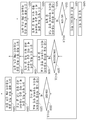
도 7은 본 발명의 실시 예에 따른 에너지 저장 장치에서, 충전 동작 시의 운용 방법을 단계별로 설명하기 위한 흐름도이다.FIG. 7 is a flowchart for explaining a step-by-step operation method in the charging operation in the energy storage device according to the embodiment of the present invention.
도 7을 참조하면, 에너지 저장부(113)는 우선적으로 운전 모드가 충전 모드로 결정되면, 충전 동작을 개시한다(100단계).Referring to FIG. 7, the
상기 충전 동작이 개시되면, 드룹 제어부(111)는 상기 에너지 저장부(113)에 충전 전원을 공급하는 전력 변환부의 동작을 제어하기 위하여, 상기 에너지 저장부(113)의 충전 상태를 확인한다(105단계).When the charging operation is started, the
그리고, 상기 드룹 제어부(111)는 상기 확인한 충전 상태가 제 1 기준 값보다 낮은지 여부를 판단한다(110단계). 즉, 상기 드룹 제어부(111)는 상기 확인한 충전 상태가 85% 미만인지 여부를 판단한다.Then, the
이어서, 드룹 제어부(111)는 상기 확인한 충전 상태가 제1 기준 값 미만이면, 기준 드룹 계수를 적용하여 상기 에너지 저장부(113)의 충전 목표 값을 설정한다(115단계). 여기에서, 상기 충전 목표 값은 유효 전력의 목표 값을 의미한다.Next, in
그리고, 드룹 제어부(111)는 상기 충전 목표 값이 설정되면, 상기 설정된 충전 목표 값에 제 1 게인 값을 적용하여 최종 충전 목표 값을 설정한다(120단계). 여기에서, 상기 제 1 게인 값은 1이다.When the charging target value is set, the
이어서, 드룹 제어부(111)는 상기 결정된 최종 충전 목표 값을 이용하여 전력 변환부의 제어를 위한 PWM 신호를 출력한다(125단계).Next, the
또한, 드룹 제어부(111)는 상기 확인한 충전 상태가 제 1 기준 값보다 높으면, 상기 충전 상태가 제 2 기준 값보다 낮은지 여부를 판단한다(130단계). 여기에서, 상기 제 2 기준 값은 90%이다.If the determined charging state is higher than the first reference value, the
이어서, 드룹 제어부(111)는 상기 확인한 충전 상태가 제 2 기준 값 미만이면, 기준 드룹 계수를 적용하여 에너지 저장부(113)의 충전 목표 값을 설정한다(135단계).If the determined charging state is less than the second reference value, the
그리고, 드룹 제어부(111)는 상기 설정한 충전 목표 값에 제 2 게인 값을 적용하여 최종 충전 목표 값을 설정한다(140단계). 여기에서, 상기 제 2 게인 값은 0보다 크고 1보다 작은 값을 가진다. 바람직하게, 상기 제 2 게인 값은 0.5이다.Then, the
이어서, 드룹 제어부(111)는 상기 제 2 게인 값이 적용되어 설정된 최종 충전 목표 값을 토대로 전력 변환부의 제어를 위한 PWM 신호를 출력한다(145단계).Next, the
또한, 드룹 제어부(111)는 상기 확인한 충전 상태가 제 1 기준 값과 2 기준 값 사이에 존재하지 않으면, 상기 충전 상태가 제 2 기준 값보다 높은지 여부를 판단한다(150단계). 여기에서, 상기 제 2 기준 값은 90%이다.If the determined charging state does not exist between the first reference value and the second reference value, the
이어서, 드룹 제어부(111)는 상기 확인한 충전 상태가 제 2 기준 값보다 높으면, 기준 드룹 계수를 적용하여 에너지 저장부(113)의 충전 목표 값을 설정한다(155단계).If the determined charging state is higher than the second reference value, the
그리고, 드룹 제어부(111)는 상기 설정한 충전 목표 값에 제 3 게인 값을 적용하여 최종 충전 목표 값을 설정한다(160단계). 여기에서, 상기 제 3 게인 값은 0이다.Then, the
이어서, 드룹 제어부(111)는 상기 제 3 게인 값이 적용되어 설정된 최종 충전 목표 값을 토대로 전력 변환부의 제어를 위한 PWM 신호를 출력한다(165단계).Then, the
도 8은 본 발명의 실시 예에 따른 에너지 저장 장치에서, 방전 동작 시의 운용 방법을 단계별로 설명하기 위한 흐름도이다.FIG. 8 is a flowchart for explaining a step-by-step operation method in a discharge operation in the energy storage device according to the embodiment of the present invention.
도 8을 참조하면, 에너지 저장부(113)는 우선적으로 운전 모드가 충전 모드로 결정되면, 방전 동작을 개시한다(200단계).Referring to FIG. 8, when the
상기 방전 동작이 개시되면, 드룹 제어부(111)는 상기 에너지 저장부(113)를 방전시키는 전력 변환부의 동작을 제어하기 위하여, 상기 에너지 저장부(113)의 충전 상태를 확인한다(205단계).When the discharging operation is started, the
그리고, 상기 드룹 제어부(111)는 상기 확인한 충전 상태가 제 3 기준 값보다 높은지 여부를 판단한다(210단계). 즉, 상기 드룹 제어부(111)는 상기 확인한 충전 상태가 25%보다 높은지 여부를 판단한다.In
이어서, 드룹 제어부(111)는 상기 확인한 충전 상태가 제3 기준 값보다, 기준 드룹 계수를 적용하여 상기 에너지 저장부(113)의 방전 목표 값을 설정한다(215단계). 여기에서, 상기 방전 목표 값은 유효 전력의 목표 값을 의미한다.Next, in step 215, the
그리고, 드룹 제어부(111)는 상기 방전 목표 값이 설정되면, 상기 설정된 방전 목표 값에 제 1 게인 값을 적용하여 최종 방전 목표 값을 설정한다(220단계). 여기에서, 상기 제 1 게인 값은 1이다.When the discharge target value is set, the
이어서, 드룹 제어부(111)는 상기 결정된 최종 충전 목표 값을 이용하여 전력 변환부의 제어를 위한 PWM 신호를 출력한다(225단계).Next, the
또한, 드룹 제어부(111)는 상기 확인한 충전 상태가 제 3 기준 값보다 낮으면, 상기 충전 상태가 제 4 기준 값보다 높은지 여부를 판단한다(230단계). 여기에서, 상기 제 4 기준 값은 20%이다.If the determined charge state is lower than the third reference value, the
이어서, 드룹 제어부(111)는 상기 확인한 방전 상태가 제 4 기준 값보다 높으면, 기준 드룹 계수를 적용하여 에너지 저장부(113)의 방전 목표 값을 설정한다(235단계).If the determined discharge state is higher than the fourth reference value, the
그리고, 드룹 제어부(111)는 상기 설정한 방전 목표 값에 제 2 게인 값을 적용하여 최종 방전 목표 값을 설정한다(240단계). 여기에서, 상기 제 2 게인 값은 0보다 크고 1보다 작은 값을 가진다. 바람직하게, 상기 제 2 게인 값은 0.5이다.Then, the
이어서, 드룹 제어부(111)는 상기 제 2 게인 값이 적용되어 설정된 최종 방전 목표 값을 토대로 전력 변환부의 제어를 위한 PWM 신호를 출력한다(245단계).Then, the
또한, 드룹 제어부(111)는 상기 확인한 충전 상태가 제 3 기준 값과 4 기준 값 사이에 존재하지 않으면, 상기 충전 상태가 제 4 기준 값보다 낮은지 여부를 판단한다(250단계). 여기에서, 상기 제 4 기준 값은 20%이다.If the determined charging state does not exist between the third reference value and the fourth reference value, the
이어서, 드룹 제어부(111)는 상기 확인한 충전 상태가 제 4 기준 값보다 낮으면, 기준 드룹 계수를 적용하여 에너지 저장부(113)의 방전 목표 값을 설정한다(255단계).If the determined charging state is lower than the fourth reference value, the
그리고, 드룹 제어부(111)는 상기 설정한 방전 목표 값에 제 3 게인 값을 적용하여 최종 방전 목표 값을 설정한다(260단계). 여기에서, 상기 제 3 게인 값은 0이다.Then, the
이어서, 드룹 제어부(111)는 상기 제 3 게인 값이 적용되어 설정된 최종 방전 목표 값을 토대로 전력 변환부의 제어를 위한 PWM 신호를 출력한다(265단계).In operation 265, the
본 발명에 따른 실시 예에 의하면, 에너지 저장 장치의 충전 동작 모드에서, 배터리의 충전 상태가 기설정된 제 1 기준 값을 초과하면 게인 값 변경을 통해 충전 속도를 감소시키고, 상기 충전 상태가 상기 제 1 기준 값보다 큰 제 2 기준 값을 초과하면 상기 변경된 게인 값의 재변경을 통해 상기 충전 동작이 중지될 수 있도록 함으로써, 상기 배터리가 과충전되는 것을 사전에 방지하여 배터리를 보호하고 안정적으로 운용될 수 있도록 한다.According to the embodiment of the present invention, in the charge operation mode of the energy storage device, when the charge state of the battery exceeds the predetermined first reference value, the charge rate is decreased by changing the gain value, The charging operation can be stopped by re-changing the changed gain value if the second reference value is larger than the reference value so that the battery is prevented from overcharging in advance to protect the battery and operate stably do.
또한, 본 발명에 따른 실시 예에 의하면, 에너지 저장 장치의 방전 동작 모드에서, 배터리의 충전 상태가 기설정된 제 3 기준 값 미만으로 감소하면 게인 값의 변경을 통해 방전 속도를 감소시킬 수 있도록 하고, 상기 방전 상태가 상기 제 3 기준 값보다 작은 제 4 기준 값 미만으로 감소하면 상기 변경된 게인 값의 재변경을 통해 상기 방전 동작이 중지될 수 있도록 함으로써, 상기 배터리가 과방전되는 것을 사전에 방지하여 배터리를 보호하고 안정적으로 운용될 수 있도록 한다.According to the embodiment of the present invention, in the discharge operation mode of the energy storage device, when the state of charge of the battery is decreased to a value less than a predetermined third reference value, the discharge speed can be reduced by changing the gain value, If the discharge state is reduced to a value less than a fourth reference value smaller than the third reference value, the discharge operation can be stopped by re-changing the changed gain value, thereby preventing the battery from being overdischarged in advance, So that it can be operated stably.
이상에서 실시예들에 설명된 특징, 구조, 효과 등은 적어도 하나의 실시예에 포함되며, 반드시 하나의 실시예에만 한정되는 것은 아니다. 나아가, 각 실시예에서 예시된 특징, 구조, 효과 등은 실시예들이 속하는 분야의 통상의 지식을 가지는 자에 의해 다른 실시예들에 대해서도 조합 또는 변형되어 실시 가능하다. 따라서 이러한 조합과 변형에 관계된 내용들은 실시예의 범위에 포함되는 것으로 해석되어야 할 것이다.The features, structures, effects and the like described in the embodiments are included in at least one embodiment and are not necessarily limited to only one embodiment. Furthermore, the features, structures, effects and the like illustrated in the embodiments can be combined and modified by other persons skilled in the art to which the embodiments belong. Accordingly, the contents of such combinations and modifications should be construed as being included in the scope of the embodiments.
이상에서 실시예를 중심으로 설명하였으나 이는 단지 예시일 뿐 실시예를 한정하는 것이 아니며, 실시예가 속하는 분야의 통상의 지식을 가진 자라면 본 실시예의 본질적인 특성을 벗어나지 않는 범위에서 이상에 예시되지 않은 여러 가지의 변형과 응용이 가능함을 알 수 있을 것이다. 예를 들어, 실시예에 구체적으로 나타난 각 구성 요소는 변형하여 실시할 수 있는 것이다. 그리고 이러한 변형과 응용에 관계된 차이점들은 첨부된 청구 범위에서 설정하는 실시예의 범위에 포함되는 것으로 해석되어야 할 것이다.While the present invention has been particularly shown and described with reference to exemplary embodiments thereof, it will be understood by those skilled in the art that various changes in form and details may be made therein without departing from the spirit and scope of the invention. It can be seen that the modification and application of branches are possible. For example, each component specifically shown in the embodiments can be modified and implemented. It is to be understood that the present invention may be embodied in many other specific forms without departing from the spirit or essential characteristics thereof.
101: 발전 장치
103: 직류/교류 컨버터
105: 교류 필터
107: 교류/교류 컨버터
109: 계통
111: 드룹 제어부
113: 에너지 저장부
115: 시스템 제어부
117: 부하
121: 직류/직류 컨버터101: Generator
103: DC / AC converter
105: AC filter
107: AC / AC converter
109: System
111:
113: Energy storage unit
115:
117: Load
121: DC / DC converter
Claims (15)
충전 모드에서 상기 전력 공급부를 통해 공급되는 전력에 의해 충전되고, 방전 모드에서 기저장한 전력을 방전하는 에너지 저장부;
상기 충전 모드에서 상기 전력 공급부를 통해 공급되는 전력을 변환하여 상기 에너지 저장부에 공급하고, 상기 방전 모드에서 상기 에너지 저장부에 저장된 전력을 변환하여 외부로 출력하는 전력 변환부; 및
상기 에너지 저장부의 운전 모드에 따른 충전 동작 또는 방전 동작이 수행되도록 상기 전력 변환부에 스위칭 신호를 출력하는 시스템 제어부를 포함하며,
상기 시스템 제어부는,
상기 에너지 저장부의 운전 모드 및 충전 상태(SOC:State Of Charge)를 확인하고, 상기 확인한 운전 모드 및 충전 상태에 따라 서로 다른 게인 값을 적용하여 상기 에너지 저장부의 목표 값을 설정하고, 상기 설정된 목표 값에 대응하는 스위칭 신호를 출력하는 드룹 제어부를 포함하는
에너지 저장 장치.A power supply unit for supplying power;
An energy storage unit that is charged by the power supplied through the power supply unit in the charge mode and discharges the stored power in the discharge mode;
A power conversion unit for converting power supplied through the power supply unit in the charge mode and supplying the converted power to the energy storage unit, and converting the power stored in the energy storage unit in the discharge mode to output the power to the outside; And
And a system controller for outputting a switching signal to the power conversion unit to perform a charging operation or a discharging operation according to an operation mode of the energy storage unit,
The system control unit includes:
(SOC) of the energy storage unit, sets a target value of the energy storage unit by applying different gain values according to the determined operation mode and the charged state, And a drupop control unit for outputting a switching signal corresponding to
Energy storage device.
상기 에너지 저장부는,
상기 충전 모드에서, 제 1 기울기에 따른 충전 속도에 의해 충전이 이루어지는 충전 구동 영역과,
상기 충전 모드에서, 상기 제 1 기울기 보다 낮은 제 2 기울기에 따른 충전 속도에 의해 충전이 이루어지는 충전 데드 밴드 영역을 포함하는
에너지 저장 장치.The method according to claim 1,
The energy storage unit may include:
A charge drive region in which charging is performed by a charging rate according to a first slope in the charging mode,
And a charge deadband region in which, in the charge mode, charging is performed by a charge rate along a second slope lower than the first slope,
Energy storage device.
상기 에너지 저장부는,
상기 방전 모드에서, 제 1 기울기에 따른 방전 속도에 의해 방전이 이루어지는 방전 구동 영역과,
상기 방전 모드에서, 상기 제 1 기울기 보다 낮은 제 2 기울기에 따른 방전 속도에 의해 방전이 이루어지는 방전 데드 밴드 영역을 포함하는
에너지 저장 장치.The method according to claim 1,
The energy storage unit may include:
A discharge driving region in which, in the discharge mode, a discharge is caused by a discharge rate according to a first slope;
And a discharge dead band region in which, in the discharge mode, discharge is performed at a discharge rate along a second slope lower than the first slope
Energy storage device.
상기 드룹 제어부는,
상기 에너지 저장부의 운전 모드가 충전 모드이고, 상기 충전 상태가 제 1 기준 값 미만이면, 제 1 게인 값을 적용하여 상기 에너지 저장부의 목표 값을 설정하고,
상기 충전 상태가 제과 제 2 기준 값 사이에 존재하면, 제 2 게인 값을 적용하여 상기 에너지 저장부의 목표 값을 설정하는
에너지 저장 장치.The method according to claim 1,
Wherein the droop control unit comprises:
And setting a target value of the energy storage unit by applying a first gain value when the operation mode of the energy storage unit is a charge mode and the charge state is less than a first reference value,
If the charged state is present between the second reference value and the second reference value, a second gain value is applied to set the target value of the energy storage unit
Energy storage device.
상기 제 1 게인 값은,
상위 제어기로부터 전송된 목표 값을 이용하여 상기 에너지 저장부의 목표 값을 설정하기 위한 값이며,
상기 제 2 게인 값은
상기 상위 제어기의 목표 값을 이용하여 설정된 상기 에너지 저장부의 목표 값을 감소시키기 위한 값인
에너지 저장 장치.5. The method of claim 4,
Wherein the first gain value is a gain value,
A value for setting a target value of the energy storage unit using a target value transmitted from the host controller,
The second gain value
And a value for decreasing a target value of the energy storage unit set using the target value of the host controller
Energy storage device.
상기 드룹 제어부는,
상기 에너지 저장부의 운전 모드가 충전 모드이고, 상기 충전 상태가 제 2 기준 값보다 크면, 제 3 게인 값을 적용하여 상기 에너지 저장부의 목표 값을 설정하는
에너지 저장 장치. 5. The method of claim 4,
Wherein the droop control unit comprises:
If the operation mode of the energy storage unit is a charge mode and the charge state is greater than a second reference value, a third gain value is applied to set a target value of the energy storage unit
Energy storage device.
상기 제 3 게인 값은 상기 에너지 저장부의 목표 값을 0으로 설정하기 위한 값인
에너지 저장 장치.The method according to claim 6,
The third gain value is a value for setting the target value of the energy storage unit to 0
Energy storage device.
상기 드룹 제어부는,
상기 에너지 저장부의 운전 모드가 방전 모드이고, 상기 충전 상태가 제 3 기준 값보다 크면, 제 1 게인 값을 적용하여 상기 에너지 저장부의 목표 값을 설정하고,
상기 충전 상태가 제 3 기준 값과 제 4 기준 값 사이에 존재하면, 제 2 게인 값을 적용하여 상기 에너지 저장부의 목표 값을 설정하는
에너지 저장 장치.The method according to claim 1,
Wherein the droop control unit comprises:
Wherein when the operation mode of the energy storage unit is a discharge mode and the charge state is greater than a third reference value, a first gain value is applied to set a target value of the energy storage unit,
When the charged state is present between the third reference value and the fourth reference value, a second gain value is applied to set the target value of the energy storage unit
Energy storage device.
상기 드룹 제어부는,
상기 에너지 저장부의 운전 모드가 방전 모드이고, 상기 충전 상태가 제 4 기준 값보다 작으면, 제 3 게인 값을 적용하여 상기 에너지 저장부의 목표 값을 설정하며,
상기 제 3 게인 값은 상기 에너지 저장부의 목표 값을 0으로 설정하기 위한 값인
에너지 저장 장치.9. The method of claim 8,
Wherein the droop control unit comprises:
And setting a target value of the energy storage unit by applying a third gain value when the operation mode of the energy storage unit is a discharge mode and the charge state is less than a fourth reference value,
The third gain value is a value for setting the target value of the energy storage unit to 0
Energy storage device.
상기 에너지 저장부의 목표 값은,
계통의 주파수 및 주파수 드롭 계수에 따른 유효 전력의 목표 값인
에너지 저장 장치.The method according to claim 1,
Wherein the target value of the energy storage unit
The target value of the active power according to the frequency and frequency drop coefficients of the system
Energy storage device.
상기 제 1 차이 값에 기설정된 주파수 드롭 계수를 곱하여 드롭 제어를 위한 유효 전력의 드룹 기준 값을 출력하는 단계;
상기 출력된 유효 전력의 드룹 기준 값과 유효 전력의 지령 값을 더하여 유효 전력의 목표 값을 결정하는 단계;
에너지 저장부의 운전 모드 및 상기 에너지 저장부의 충전 상태에 따라 상기 유효 전력의 목표 값에 적용될 게인 값을 결정하는 단계; 및
상기 결정된 게인 값을 적용하여 유효 전력의 최종 목표 값을 출력하는 단계를 포함하는
에너지 저장 장치의 동작 방법.Outputting a first difference value according to a difference between a reference frequency value and a current frequency value of the system;
Multiplying the first difference value by a predetermined frequency drop coefficient to output a droop reference value of effective power for drop control;
Determining a target value of active power by adding a droop reference value of the output active power and a command value of active power;
Determining a gain value to be applied to a target value of the active power according to an operation mode of the energy storage unit and a charging state of the energy storage unit; And
And outputting the final target value of the active power by applying the determined gain value
A method of operating an energy storage device.
상기 게인 값은,
상기 결정된 유효 전력의 목표 값과 동일한 상기 유효 전력의 최종 목표 값을 출력하기 위한 제 1 게인 값과,
상기 결정된 유효 전력의 목표 값보다 작은 상기 유효 전력의 최종 목표 값을 출력하기 위한 제 2 게인 값을 포함하는
에너지 저장 장치의 동작 방법.12. The method of claim 11,
The gain value may be,
A first gain value for outputting a final target value of the active power equal to the target value of the determined active power,
And a second gain value for outputting a final target value of the active power smaller than the target value of the determined active power
A method of operating an energy storage device.
상기 게인 값은,
상기 유효 전력의 최종 목표 값을 0으로 결정하기 위한 제 3 게인 값을 더 포함하는
에너지 저장 장치의 동작 방법.13. The method of claim 12,
The gain value may be,
Further comprising a third gain value for determining the final target value of the active power as zero
A method of operating an energy storage device.
상기 게인 값을 결정하는 단계는,
상기 에너지 저장부의 운전 모드가 충전 모드이고, 상기 충전 상태가 제 1 기준 값 미만이면, 상기 제 1 게인 값을 상기 적용될 게인 값으로 결정하는 단계와,
상기 에너지 저장부의 운전 모드가 충전 모드이고, 상기 충전 상태가 제 1 기준 값과 제 2 기준 값 사이에 존재하면, 상기 제 2 게인 값을 상기 적용될 게인 값으로 결정하는 단계와,
상기 에너지 저장부의 운전 모드가 충전 모드이고, 상기 충전 상태가 상기 제 2 기준 값보다 크면, 상기 제 3 게인 값을 상기 적용될 게인 값으로 결정하는 단계를 포함하는
에너지 저장 장치의 동작 방법.14. The method of claim 13,
Wherein determining the gain value comprises:
Determining the first gain value as the gain value to be applied if the operation mode of the energy storage unit is a charge mode and the charge state is less than a first reference value,
Determining the second gain value as the gain value to be applied if the operation mode of the energy storage unit is a charge mode and the charge state exists between a first reference value and a second reference value;
Determining the third gain value as the gain value to be applied if the operation mode of the energy storage unit is a charge mode and the charge state is greater than the second reference value
A method of operating an energy storage device.
상기 게인 값을 결정하는 단계는,
상기 에너지 저장부의 운전 모드가 방전 모드이고, 상기 충전 상태가 제 3 기준 값보다 크면, 상기 제 1 게인 값을 상기 적용될 게인 값으로 결정하는 단계와,
상기 에너지 저장부의 운전 모드가 방전 모드이고, 상기 충전 상태가 제 3 기준 값과 제 4 기준 값 사이에 존재하면, 상기 제 2 게인 값을 상기 적용될 게인 값으로 결정하는 단계와,
상기 에너지 저장부의 운전 모드가 방전 모드이고, 상기 충전 상태가 제 4 기준 값 미만이면, 상기 제 3 게인 값을 상기 적용될 게인 값으로 결정하는 단계를 포함하는
에너지 저장 장치의 동작 방법.14. The method of claim 13,
Wherein determining the gain value comprises:
Determining the first gain value as the gain value to be applied if the operation mode of the energy storage unit is in a discharge mode and the charge state is greater than a third reference value,
Determining the second gain value as the gain value to be applied if the operation mode of the energy storage unit is in a discharge mode and the charge state exists between a third reference value and a fourth reference value,
And determining the third gain value as the gain value to be applied if the operation mode of the energy storage unit is in a discharge mode and the charge state is less than a fourth reference value
A method of operating an energy storage device.
Priority Applications (1)
| Application Number | Priority Date | Filing Date | Title |
|---|---|---|---|
| KR1020150106897A KR20170013772A (en) | 2015-07-28 | 2015-07-28 | Energy storge system and metoh for operating thereof |
Applications Claiming Priority (1)
| Application Number | Priority Date | Filing Date | Title |
|---|---|---|---|
| KR1020150106897A KR20170013772A (en) | 2015-07-28 | 2015-07-28 | Energy storge system and metoh for operating thereof |
Publications (1)
| Publication Number | Publication Date |
|---|---|
| KR20170013772A true KR20170013772A (en) | 2017-02-07 |
Family
ID=58108058
Family Applications (1)
| Application Number | Title | Priority Date | Filing Date |
|---|---|---|---|
| KR1020150106897A KR20170013772A (en) | 2015-07-28 | 2015-07-28 | Energy storge system and metoh for operating thereof |
Country Status (1)
| Country | Link |
|---|---|
| KR (1) | KR20170013772A (en) |
Cited By (8)
| Publication number | Priority date | Publication date | Assignee | Title |
|---|---|---|---|---|
| WO2018236038A1 (en) * | 2017-06-21 | 2018-12-27 | 엘에스산전 주식회사 | Energy storage system |
| WO2019143068A1 (en) * | 2018-01-19 | 2019-07-25 | 엘에스산전 주식회사 | Photovoltaic power generation apparatus |
| WO2019146900A1 (en) * | 2018-01-25 | 2019-08-01 | 엘지이노텍 주식회사 | Direct current-direct current converter and power conversion method therefor |
| CN111900750A (en) * | 2020-06-17 | 2020-11-06 | 西安交通大学 | Virtual synchronous machine control method based on two-stage energy storage converter system |
| CN112103976A (en) * | 2020-09-18 | 2020-12-18 | 许继集团有限公司 | Energy storage power station regulation and control system and communication control method |
| US11146075B2 (en) | 2019-10-02 | 2021-10-12 | Korea Institute Of Energy Research | Charge/discharge control apparatus and method of energy storage system, and energy charge/discharge control system and method |
| KR102344499B1 (en) * | 2021-02-03 | 2021-12-28 | 라이트시스템 주식회사 | Electronic device for determining state of charge based on charge factor and method for operating thereof |
| CN113949135A (en) * | 2021-11-02 | 2022-01-18 | 燕山大学 | Energy storage SOC recovery control method |
-
2015
- 2015-07-28 KR KR1020150106897A patent/KR20170013772A/en unknown
Cited By (11)
| Publication number | Priority date | Publication date | Assignee | Title |
|---|---|---|---|---|
| WO2018236038A1 (en) * | 2017-06-21 | 2018-12-27 | 엘에스산전 주식회사 | Energy storage system |
| KR20180138353A (en) * | 2017-06-21 | 2018-12-31 | 엘에스산전 주식회사 | An energy storage system |
| WO2019143068A1 (en) * | 2018-01-19 | 2019-07-25 | 엘에스산전 주식회사 | Photovoltaic power generation apparatus |
| WO2019146900A1 (en) * | 2018-01-25 | 2019-08-01 | 엘지이노텍 주식회사 | Direct current-direct current converter and power conversion method therefor |
| US11146075B2 (en) | 2019-10-02 | 2021-10-12 | Korea Institute Of Energy Research | Charge/discharge control apparatus and method of energy storage system, and energy charge/discharge control system and method |
| CN111900750A (en) * | 2020-06-17 | 2020-11-06 | 西安交通大学 | Virtual synchronous machine control method based on two-stage energy storage converter system |
| CN111900750B (en) * | 2020-06-17 | 2022-04-22 | 西安交通大学 | Virtual synchronous machine control method based on two-stage energy storage converter system |
| CN112103976A (en) * | 2020-09-18 | 2020-12-18 | 许继集团有限公司 | Energy storage power station regulation and control system and communication control method |
| KR102344499B1 (en) * | 2021-02-03 | 2021-12-28 | 라이트시스템 주식회사 | Electronic device for determining state of charge based on charge factor and method for operating thereof |
| CN113949135A (en) * | 2021-11-02 | 2022-01-18 | 燕山大学 | Energy storage SOC recovery control method |
| CN113949135B (en) * | 2021-11-02 | 2023-09-22 | 燕山大学 | Energy storage SOC recovery control method |
Similar Documents
| Publication | Publication Date | Title |
|---|---|---|
| KR20170013772A (en) | Energy storge system and metoh for operating thereof | |
| US10464441B2 (en) | Charging facility and energy management method for charging facility | |
| Khan et al. | Fuzzy logic based energy storage management system for MVDC power system of all electric ship | |
| US10766630B2 (en) | Direct current stabilization power supply system | |
| WO2016185661A1 (en) | Distributed power system, and control method of distributed power system | |
| US20130181519A1 (en) | Power conversion system for energy storage system and controlling method of the same | |
| Jin et al. | Coordinated secondary control for autonomous hybrid three-port AC/DC/DS microgrid | |
| US10389128B2 (en) | Power control system | |
| CN110637403B (en) | Hybrid energy storage system | |
| CA2935019A1 (en) | Temperature control apparatus for electricity storage device | |
| CN111817326B (en) | Distributed energy storage SOC control and integration method under alternating current micro-grid island mode | |
| Tariq et al. | A Lithium-ion battery energy storage system using a bidirectional isolated DC-DC converter with current mode control for More Electric Aircraft | |
| Kwon et al. | Load frequency-based power management for shipboard DC hybrid power systems | |
| WO2017090155A1 (en) | Power control device and power control system | |
| Shi et al. | A dynamic voltage transient suppression control strategy for microgrid inverter | |
| Kim et al. | Coordinated droop control for stand-alone DC micro-grid | |
| KR20170013773A (en) | Energy storage system | |
| Narvaez et al. | Topologies for battery and supercapacitor interconnection in residential microgrids with intermittent generation | |
| Männel et al. | Investigation on an AC Grid Failure Handling of Industrial DC Microgrids with an Energy Storage | |
| Rani et al. | A variable power reaching law-based integral sliding mode controller design to maintain power sharing in DC microgrids | |
| US9768634B2 (en) | Facility for controlling charge current for storage units in electrical energy supply grids connecting distributed generators and distributed storage units, among others | |
| Gui et al. | A novel coordinated control of renewable energy sources and energy storage system in islanded microgrid | |
| Makrygiorgou et al. | Nonlinear modeling, control and stability analysis of a hybrid ac/dc distributed generation system | |
| Han et al. | Operation analysis of coordinated droop control for stand-alone DC microgrid | |
| Bai et al. | Modular design of cascaded H-bridge for community energy storage systems by using secondary traction batteries |