KR20140118770A - Display device - Google Patents
Display device Download PDFInfo
- Publication number
- KR20140118770A KR20140118770A KR1020140030430A KR20140030430A KR20140118770A KR 20140118770 A KR20140118770 A KR 20140118770A KR 1020140030430 A KR1020140030430 A KR 1020140030430A KR 20140030430 A KR20140030430 A KR 20140030430A KR 20140118770 A KR20140118770 A KR 20140118770A
- Authority
- KR
- South Korea
- Prior art keywords
- display
- transmissive
- light emitting
- display panel
- light
- Prior art date
Links
- 238000000034 method Methods 0.000 claims description 17
- 239000004973 liquid crystal related substance Substances 0.000 claims description 3
- ORQBXQOJMQIAOY-UHFFFAOYSA-N nobelium Chemical compound [No] ORQBXQOJMQIAOY-UHFFFAOYSA-N 0.000 description 87
- 239000011159 matrix material Substances 0.000 description 6
- 238000004519 manufacturing process Methods 0.000 description 2
- 238000005259 measurement Methods 0.000 description 2
- 150000002894 organic compounds Chemical class 0.000 description 2
- 239000000758 substrate Substances 0.000 description 2
- 230000005540 biological transmission Effects 0.000 description 1
- JBTHDAVBDKKSRW-UHFFFAOYSA-N chembl1552233 Chemical compound CC1=CC(C)=CC=C1N=NC1=C(O)C=CC2=CC=CC=C12 JBTHDAVBDKKSRW-UHFFFAOYSA-N 0.000 description 1
- 238000005401 electroluminescence Methods 0.000 description 1
- 238000000605 extraction Methods 0.000 description 1
- 238000010030 laminating Methods 0.000 description 1
- 230000003252 repetitive effect Effects 0.000 description 1
- 238000000926 separation method Methods 0.000 description 1
Images


Classifications
-
- G—PHYSICS
- G02—OPTICS
- G02B—OPTICAL ELEMENTS, SYSTEMS OR APPARATUS
- G02B26/00—Optical devices or arrangements for the control of light using movable or deformable optical elements
- G02B26/004—Optical devices or arrangements for the control of light using movable or deformable optical elements based on a displacement or a deformation of a fluid
- G02B26/005—Optical devices or arrangements for the control of light using movable or deformable optical elements based on a displacement or a deformation of a fluid based on electrowetting
-
- H—ELECTRICITY
- H10—SEMICONDUCTOR DEVICES; ELECTRIC SOLID-STATE DEVICES NOT OTHERWISE PROVIDED FOR
- H10K—ORGANIC ELECTRIC SOLID-STATE DEVICES
- H10K50/00—Organic light-emitting devices
- H10K50/80—Constructional details
- H10K50/84—Passivation; Containers; Encapsulations
- H10K50/841—Self-supporting sealing arrangements
-
- H—ELECTRICITY
- H10—SEMICONDUCTOR DEVICES; ELECTRIC SOLID-STATE DEVICES NOT OTHERWISE PROVIDED FOR
- H10K—ORGANIC ELECTRIC SOLID-STATE DEVICES
- H10K50/00—Organic light-emitting devices
- H10K50/80—Constructional details
- H10K50/85—Arrangements for extracting light from the devices
-
- H—ELECTRICITY
- H10—SEMICONDUCTOR DEVICES; ELECTRIC SOLID-STATE DEVICES NOT OTHERWISE PROVIDED FOR
- H10K—ORGANIC ELECTRIC SOLID-STATE DEVICES
- H10K59/00—Integrated devices, or assemblies of multiple devices, comprising at least one organic light-emitting element covered by group H10K50/00
- H10K59/10—OLED displays
- H10K59/12—Active-matrix OLED [AMOLED] displays
- H10K59/121—Active-matrix OLED [AMOLED] displays characterised by the geometry or disposition of pixel elements
-
- G—PHYSICS
- G02—OPTICS
- G02F—OPTICAL DEVICES OR ARRANGEMENTS FOR THE CONTROL OF LIGHT BY MODIFICATION OF THE OPTICAL PROPERTIES OF THE MEDIA OF THE ELEMENTS INVOLVED THEREIN; NON-LINEAR OPTICS; FREQUENCY-CHANGING OF LIGHT; OPTICAL LOGIC ELEMENTS; OPTICAL ANALOGUE/DIGITAL CONVERTERS
- G02F1/00—Devices or arrangements for the control of the intensity, colour, phase, polarisation or direction of light arriving from an independent light source, e.g. switching, gating or modulating; Non-linear optics
- G02F1/01—Devices or arrangements for the control of the intensity, colour, phase, polarisation or direction of light arriving from an independent light source, e.g. switching, gating or modulating; Non-linear optics for the control of the intensity, phase, polarisation or colour
- G02F1/13—Devices or arrangements for the control of the intensity, colour, phase, polarisation or direction of light arriving from an independent light source, e.g. switching, gating or modulating; Non-linear optics for the control of the intensity, phase, polarisation or colour based on liquid crystals, e.g. single liquid crystal display cells
-
- G—PHYSICS
- G02—OPTICS
- G02F—OPTICAL DEVICES OR ARRANGEMENTS FOR THE CONTROL OF LIGHT BY MODIFICATION OF THE OPTICAL PROPERTIES OF THE MEDIA OF THE ELEMENTS INVOLVED THEREIN; NON-LINEAR OPTICS; FREQUENCY-CHANGING OF LIGHT; OPTICAL LOGIC ELEMENTS; OPTICAL ANALOGUE/DIGITAL CONVERTERS
- G02F1/00—Devices or arrangements for the control of the intensity, colour, phase, polarisation or direction of light arriving from an independent light source, e.g. switching, gating or modulating; Non-linear optics
- G02F1/01—Devices or arrangements for the control of the intensity, colour, phase, polarisation or direction of light arriving from an independent light source, e.g. switching, gating or modulating; Non-linear optics for the control of the intensity, phase, polarisation or colour
- G02F1/15—Devices or arrangements for the control of the intensity, colour, phase, polarisation or direction of light arriving from an independent light source, e.g. switching, gating or modulating; Non-linear optics for the control of the intensity, phase, polarisation or colour based on an electrochromic effect
- G02F1/153—Constructional details
- G02F1/157—Structural association of cells with optical devices, e.g. reflectors or illuminating devices
-
- G—PHYSICS
- G02—OPTICS
- G02F—OPTICAL DEVICES OR ARRANGEMENTS FOR THE CONTROL OF LIGHT BY MODIFICATION OF THE OPTICAL PROPERTIES OF THE MEDIA OF THE ELEMENTS INVOLVED THEREIN; NON-LINEAR OPTICS; FREQUENCY-CHANGING OF LIGHT; OPTICAL LOGIC ELEMENTS; OPTICAL ANALOGUE/DIGITAL CONVERTERS
- G02F2201/00—Constructional arrangements not provided for in groups G02F1/00 - G02F7/00
- G02F2201/44—Arrangements combining different electro-active layers, e.g. electrochromic, liquid crystal or electroluminescent layers
Abstract
Description
본 발명은 표시 패널 및 표시 장치, 그리고 이들을 제작하는 방법에 관한 것이다. 특히, 가시광을 투과시키는 표시 패널 및 표시 장치, 그리고 이들을 제작하는 방법에 관한 것이다.The present invention relates to a display panel and a display device, and a method of manufacturing the same. In particular, the present invention relates to a display panel and a display device which transmit visible light, and a method of manufacturing the same.
근년에 들어, 표시 장치는 다양한 용도로의 응용이 기대되고 있으며, 다양화가 요구되고 있다.In recent years, display devices are expected to be used in various applications, and diversification is demanded.
일렉트로루미네선스(EL: Electroluminescence)를 이용한 발광 소자(EL 소자라고도 기재함)는, 박형 경량화가 용이하다, 입력 신호에 대하여 고속으로 응답하는 것이 가능하다, 직류 저전압 전원을 사용한 구동이 가능하다 등의 특징을 갖고 있으며, 표시 장치로 응용하기가 검토되고 있다(특허문헌 1 등).A light emitting element (also referred to as an EL element) using electroluminescence is easy to be made thin and lightweight, can respond at high speed to an input signal, can be driven by using a DC low voltage power supply, etc. And has been studied as a display device (Patent Document 1, etc.).
또한, 헤드 마운트 디스플레이 등의 웨어러블 디스플레이(wearable display)나, 헤드 업 디스플레이, 자동차의 창유리 등에 이용하기 위하여, 표시부의 화상과 사용자의 전방(前方)의 풍경을 겹쳐서 볼 수 있는 표시 장치(시스루 기능을 갖는 표시 장치나 투명한 표시 장치라고도 할 수 있음)가 요구되고 있다.In addition, a display device (a see-through function) capable of superimposing an image of a display portion and a user's front landscape for use in a wearable display such as a head mount display, a head-up display, (Which may be referred to as a display device or a transparent display device).
또한, 웨어러블 디스플레이 등 휴대용 표시 장치에서는 저소비 전력화가 요구되고 있다.In portable display devices such as wearable displays, reduction in power consumption is also demanded.
발광 소자를 사용한 표시 장치는, 어두운 장소에 비하여 밝은 장소에서는 발광 화소와 비발광 화소의 밝기의 차이가 작으며 시인성이 저하된다.In a display device using a light emitting element, a difference in brightness between a light emitting pixel and a non-light emitting pixel is small in a bright place as compared with a dark place, and visibility is lowered.
따라서, 본 발명의 일 형태는 신규한 표시 패널 또는 표시 장치를 제공하는 것을 목적 중 하나로 한다. 또한, 본 발명의 일 형태는 소비 전력이 낮은 표시 패널 또는 표시 장치를 제공하는 것을 목적 중 하나로 한다. 또한, 본 발명의 일 형태는 주위의 밝기에 의존하지 않고 시인성이 높은 표시 패널 또는 표시 장치를 제공하는 것을 목적 중 하나로 한다. 또한, 본 발명의 일 형태는 웨어러블 디스플레이 등 사용자 측으로부터 외광을 충분히 얻을 수 없는 용도에서도, 주위의 밝기에 의존하지 않고 시인성이 높은 표시 패널 또는 표시 장치를 제공하는 것을 목적 중 하나로 한다.Therefore, one aspect of the present invention is to provide a novel display panel or display device. It is another object of the present invention to provide a display panel or display device with low power consumption. It is another object of the present invention to provide a display panel or display device having high visibility without depending on ambient brightness. It is another object of the present invention to provide a display panel or display device having high visibility without depending on the brightness of the surroundings, even in applications where wear of the wearable display or the like is not sufficiently obtained from the user's side.
본 발명의 일 형태는 적어도 한쪽 면에서 표시가 가능하며 투과형 표시 소자를 통하여 외광을 투과시키는 표시 패널이고, 각각 독립적으로 구동시키기 가능하고 상기 표시 패널의 상기 한쪽 면 측에 빛을 사출하는 복수의 발광 소자와, 각각 독립적으로 구동시키기 가능한 복수의 투과형 표시 소자를 갖는 표시 패널이다.An embodiment of the present invention is a display panel capable of being displayed on at least one surface and transmitting external light through a transmissive display element and being capable of being driven independently and having a plurality of light emission And a plurality of transmissive display elements which can be driven independently of each other.
본 발명의 일 형태인 표시 패널은 화상(정지 화상 또는 동영상)이나 정보를 표시하기 위하여 투과형 표시 소자 및 발광 소자를 사용할 수 있다.A display panel as one form of the present invention can use a transmissive display element and a light emitting element to display an image (still image or moving image) or information.
본 발명의 일 형태인 표시 패널에 있어서, 투과형 표시 소자를 사용한 표시에는 외광을 광원으로서 이용할 수 있기 때문에, 표시 패널의 소비 전력이 낮으므로 바람직하다. 표시 패널의 사용자 측의 면(표시 패널의 한쪽 면이라고도 기재함)을 통하여 표시 패널에 외광을 입사시킬 필요는 없다. 웨어러블 디스플레이 등 사용자 측으로부터 표시 패널에 외광이 충분히 입사하지 않는 용도에서도 본 발명의 일 형태인 표시 패널은 적합하다.In the display panel, which is an embodiment of the present invention, external light can be used as a light source for display using a transmissive display element, so that power consumption of the display panel is low, which is preferable. It is not necessary to make external light incident on the display panel through the user-side surface of the display panel (also referred to as one surface of the display panel). A display panel which is one form of the present invention is suitable for applications where external light is not sufficiently incident on a display panel from a user side such as a wearable display.
발광 소자를 사용한 표시는 표시 패널의 주위가 어두워도 시인성이 높아서 바람직하다.The display using the light emitting element is preferable because the visibility is high even if the periphery of the display panel is dark.
본 발명의 일 형태인 표시 패널에서는, 주위의 밝기나 표시 패널로의 외광의 입사 상황에 따라 표시를 위하여 사용하는 소자를 스위칭함으로써(투과형 표시 소자 및 발광 소자 중 어느 쪽을 사용하여 표시시킬지를 선택함으로써), 사용자는 주위의 밝기에 의존하지 않고 표시 패널의 표시를 충분히 시인할 수 있다.In the display panel according to one embodiment of the present invention, by switching the elements used for display according to the brightness of the surroundings and the incident state of the external light to the display panel (by selecting which of the transmissive display element and the light emitting element is to be displayed , The user can sufficiently visually recognize the display of the display panel without depending on the brightness of the surroundings.
상기 표시 패널이 갖는 발광 소자는 편면(片面) 발광의 발광 소자(편면 발광 소자라고도 기재함)라도 좋다. 상기 표시 패널은 상기 편면 발광 소자와 상기 투과형 표시 소자가 적층되어 있어도 좋다. 상기 편면 발광 소자는 상기 투과형 표시 소자에 비하여 표시 패널의 한쪽 면 측에 위치하여도 좋고, 상기 투과형 표시 소자는 상기 편면 발광 소자에 비하여 표시 패널의 한쪽 면 측에 위치하여도 좋다. 상기 투과형 표시 소자로서 일렉트로웨팅 소자를 사용하는 경우에는 상기 편면 발광 소자가 상기 투과형 표시 소자에 비하여 표시 패널의 한쪽 면 측에 위치하면 바람직하다.The light-emitting element of the display panel may be a light-emitting element (also referred to as a single-sided light-emitting element) emitting light of one side. The display panel may be formed by stacking the one-side light emitting element and the transmissive display element. The single-sided light emitting element may be located on one side of the display panel as compared with the transmissive display element, and the transmissive display element may be located on one side of the display panel as compared with the single-sided light emitting element. In the case of using the electrowetting element as the transmissive display element, it is preferable that the one-side light emitting element is located on one surface side of the display panel as compared with the transmissive display element.
상기 표시 패널이 갖는 발광 소자는 양면 발광의 발광 소자(양면 발광 소자라고도 기재함)라도 좋다.The light emitting element of the display panel may be a double-sided light emitting element (also referred to as a double-sided light emitting element).
구체적으로는 본 발명의 일 형태는, 양면 발광 소자 및 투과형 표시 소자를 통하여 외광을 투과시키는 표시 패널이며, 각각 독립적으로 구동하는 복수의 양면 발광 소자와, 각각 독립적으로 구동하는 복수의 투과형 표시 소자를 갖는 표시 패널이다.Specifically, one embodiment of the present invention is a display panel that transmits external light through a double-sided light-emitting element and a transmissive display element, includes a plurality of double-sided light-emitting elements that are driven independently of each other, and a plurality of transmissive display elements .
상기 표시 패널은, 양면 발광 소자와 투과형 표시 소자가 적층되어 있어도 좋다.The display panel may be a double-sided light-emitting device and a transmissive display device.
상기 각 구성을 갖는 표시 패널은, 투과형 표시 소자 하나에 대하여 발광 소자 하나를 가져도 좋고 2개 이상 가져도 좋다. 예를 들어 투과형 표시 소자로 구성되는 화소수와 발광 소자로 구성되는 화소수가 동일한 경우, 투과형 표시 소자를 사용한 표시와 발광 소자를 사용한 표시가 동등한 해상도를 가지게 되어 바람직하다.The display panel having each of the above structures may have one light emitting element or two or more light emitting elements for one transmissive display element. For example, when the number of pixels constituted by the transmissive display element and the number of pixels constituted by the light emitting element are the same, the display using the transmissive display element and the display using the light emitting element are preferably equal in resolution.
상기 각 구성에서 투과형 표시 소자는 일렉트로크로믹 소자인 것이 바람직하다. 상기 각 구성에서 발광 소자는 EL 소자인 것이 바람직하다.In each of the above configurations, the transmissive display element is preferably an electrochromic element. In each of the above structures, the light emitting element is preferably an EL element.
상기 각 구성을 갖는 표시 패널은 가요성을 가져도 좋다.The display panel having the above-described configuration may have flexibility.
또한, 본 발명의 일 형태는 상기 구성 중 어느 구성을 갖는 표시 패널과, 외광이 조사되는 수광(受光) 소자와, 수광 소자에 조사된 광량에 따라 표시 패널의 표시를 제어하는 제어 회로를 갖는 표시 장치이다.According to another aspect of the present invention, there is provided a display device comprising a display panel having any of the above structures, a light receiving element to which external light is irradiated, a display having a control circuit for controlling display of the display panel in accordance with the amount of light irradiated to the light receiving element Device.
또한, 본 발명의 일 형태는 상기 구성 중 어느 구성을 갖는 표시 패널과, 사용자가 적어도 2개의 상태를 스위칭할 수 있는 스위치와, 스위치의 상태에 따라 표시 패널의 표시를 제어하는 제어 회로를 갖는 표시 장치이다.According to another aspect of the present invention, there is provided a display device comprising a display panel having any of the above configurations, a switch capable of switching at least two states by a user, a display having a control circuit for controlling display of the display panel in accordance with the state of the switch Device.
또한, 본 명세서 중에서, 표시 장치에는, 표시 패널에 커넥터, 예를 들어 이방 도전성 필름 또는 TCP(Tape Carrier Package)가 장착된 모듈, TCP 끝에 프린트 배선판이 제공된 모듈, 또는 상기 패널에 COG(Chip On Glass) 방식으로 IC(집적 회로)가 직접 실장된 모듈도 그 범주에 포함된다.In this specification, the display device includes a module in which a connector, for example, an anisotropic conductive film or a TCP (Tape Carrier Package) is mounted on a display panel, a module in which a printed wiring board is provided on the end of TCP, ) Modules in which ICs (integrated circuits) are directly mounted.
본 발명의 일 형태에서는 소비 전력이 낮은 표시 패널 또는 표시 장치를 제공할 수 있다. 본 발명의 일 형태에서는 주위의 밝기에 의존하지 않고 시인성이 높은 표시 패널 또는 표시 장치를 제공할 수 있다. 특히, 웨어러블 디스플레이 등 사용자 측으로부터 외광을 충분히 얻을 수 없는 용도에서도 주위의 밝기에 의존하지 않고 시인성이 높은 표시 패널 또는 표시 장치를 제공할 수 있다.In one aspect of the present invention, a display panel or a display device with low power consumption can be provided. In one aspect of the present invention, a display panel or a display device having high visibility can be provided without depending on the ambient brightness. Particularly, a display panel or a display device having high visibility can be provided without depending on the brightness of the surroundings even in a use such as a wearable display in which the user can not sufficiently obtain external light.
도 1은 본 발명의 일 형태인 표시 패널을 설명한 도면.
도 2는 본 발명의 일 형태인 표시 패널을 설명한 도면.
도 3은 본 발명의 일 형태인 표시 패널을 설명한 도면.
도 4는 본 발명의 일 형태인 표시 패널을 설명한 도면.
도 5는 본 발명의 일 형태인 표시 장치를 설명한 도면.BRIEF DESCRIPTION OF THE DRAWINGS Fig. 1 is a view for explaining a display panel according to an embodiment of the present invention;
2 is a view for explaining a display panel which is an embodiment of the present invention.
3 is a view for explaining a display panel which is an embodiment of the present invention.
4 is a view for explaining a display panel according to an embodiment of the present invention.
5 is a view for explaining a display device which is an embodiment of the present invention.
실시형태에 대하여, 도면을 사용하여 자세히 설명한다. 다만, 본 발명은 이하의 설명에 한정되지 않으며, 본 발명의 취지 및 그 범위에서 벗어남이 없이 그 형태 및 자세한 내용을 다양하게 변경할 수 있는 것은 당업자라면 용이하게 이해할 수 있다. 따라서, 본 발명은 이하에 제시되는 실시형태의 기재 내용에 한정되어 해석되는 것은 아니다.Embodiments will be described in detail with reference to the drawings. It should be understood, however, by those skilled in the art that the present invention is not limited to the following description, and that various changes in form and detail may be made therein without departing from the spirit and scope of the present invention. Accordingly, the present invention is not construed as being limited to the description of the embodiments described below.
또한, 이하에서 설명하는 발명의 구성에서, 동일 부분 또는 같은 기능을 갖는 부분에서는 상이한 도면간에서 동일한 부호를 공통적으로 사용하고, 그 반복 설명은 생략한다. 또한, 같은 기능을 갖는 부분을 가리키는 경우에는 해치 패턴을 동일하게 하고 특별히 부호를 붙이지 않은 경우가 있다.Further, in the constitution of the invention described below, the same reference numerals are commonly used for different parts in the same part or the same function, and the repetitive description thereof will be omitted. In the case of pointing to a portion having the same function, the hatch pattern may be the same, and there may be a case where the sign is not particularly specified.
또한, 도면 등에 나타낸 각 구성의 위치, 크기, 범위 등은 간단히 이해할 수 있도록 실제의 위치, 크기, 범위 등을 나타내지 않은 경우가 있다. 그러므로, 개시(開示)된 발명은 도면 등에 개시된 위치, 크기, 범위 등에 반드시 한정되지 않는다.In addition, the position, size, range, and the like of each structure shown in the drawings and the like may not show the actual position, size, range, and the like so that they can be easily understood. Therefore, the disclosed invention is not necessarily limited to the position, size, range, etc. disclosed in the drawings and the like.
(실시형태 1)(Embodiment 1)
본 실시형태에서는 본 발명의 일 형태인 표시 패널에 대하여 도 1∼도 4를 사용하여 설명한다.In the present embodiment, a display panel which is one embodiment of the present invention will be described with reference to Figs. 1 to 4. Fig.
본 발명의 일 형태인 표시 패널은, 적어도 한쪽 면에서 표시가 가능하며 투과형 표시 소자를 통하여 외광을 투과시키는 표시 패널이고, 각각 독립적으로 구동 가능하고 상기 표시 패널의 상기 한쪽 면 측에 빛을 사출하는 복수의 발광 소자와, 각각 독립적으로 구동 가능한 복수의 투과형 표시 소자를 갖는다.A display panel as an embodiment of the present invention is a display panel capable of being displayed on at least one surface and transmitting external light through a transmissive display element and being capable of being independently driven and emitting light to the one surface of the display panel A plurality of light emitting elements, and a plurality of transmissive display elements that can be driven independently of each other.
본 발명의 일 형태인 표시 패널은, 투과형 표시 소자를 사용하여 화상이나 정보를 표시할 수 있고 발광 소자를 사용하여 화상이나 정보를 표시할 수 있다. 본 발명의 일 형태인 표시 패널에서는, 외광이 투과 상태의 투과형 표시 소자나 비발광 상태의 양면 발광 소자를 통하여 투과하기 때문에 사용자가 전방의 풍경을 시인할 수 있다. 또한 사용자는 표시 패널의 표시와 전방의 풍경을 겹쳐서 볼 수 있다.The display panel, which is one embodiment of the present invention, can display an image or information using a transmissive display element, and can display an image or information using a light emitting element. In the display panel according to one embodiment of the present invention, since the external light is transmitted through the transmissive display element in the transmissive state or the double-sided light-emitting element in the non-luminescent state, the user can see the landscape ahead. In addition, the user can see the display on the display panel and the scenery ahead.
발광 소자를 사용하여 표시시키는 경우에는, 복수의 발광 소자는 각각 독립적으로 발광 상태 또는 비발광 상태가 된다.When the display is performed using a light emitting element, the plurality of light emitting elements are independently in a light emitting state or a non-light emitting state.
발광 소자로서는 자발광이 가능한 소자를 사용할 수 있으며, 전류 또는 전압으로 휘도가 제어되는 소자를 그 범주에 포함한다. 예를 들어, 발광 다이오드(LED), 유기 EL 소자, 무기 EL 소자 등을 사용할 수 있다. 이들 발광 소자를 사용한 표시는, 표시 패널의 주위가 어두운 상태에서도 시인성이 높다.As the light emitting element, a device capable of self-emission can be used, and a device whose luminance is controlled by current or voltage is included in its category. For example, a light emitting diode (LED), an organic EL element, an inorganic EL element, or the like can be used. The display using these light emitting elements has high visibility even in a dark state around the display panel.
발광 소자는 액티브 매트릭스 방식이라도 패시브 매트릭스 방식이라도 좋다.The light emitting element may be an active matrix system or a passive matrix system.
투과형 표시 소자를 사용하여 표시시키는 경우, 복수의 투과형 표시 소자는 각각 독립적으로 가시광을 투과시키는 상태(투과 상태) 또는 가시광을 투과시키지 않는 상태(불투과 상태)가 된다. 예를 들어, 사용자의 전방의 풍경을 배경으로 하여 문자나 화상을 표시시킬 수 있다. 불투과 상태가 된 소자를 사용하여 문자나 화상을 표시시키고 소자가 투과 상태인 부분이 배경이 된다.When a transmissive display element is used for display, a plurality of transmissive display elements are independently in a state of transmitting visible light (transmissive state) or of a state of not transmitting visible light (not transmissive state). For example, a character or an image can be displayed with the background of the user's front as a background. A character or an image is displayed by using a device which is in a non-transmissive state, and a portion where a device is in a transmissive state becomes a background.
투과형 표시 소자로서는 가시광의 투과성의 조정이 가능한 표시 소자를 사용할 수 있고, 예를 들어 일렉트로웨팅 소자, 일렉트로크로믹 소자, 투과형 액정 소자, 미소 전기 기계 시스템(MEMS: Micro Electro Mechanical Systems)을 사용한 표시 소자 등을 사용할 수 있다. 본 발명의 일 형태인 표시 패널은, 이들 투과형 표시 소자를 사용함으로써 외광을 광원으로서 이용하여 표시시킬 수 있으며 저소비 전력화를 실현할 수 있다.As the transmissive display element, a display element capable of adjusting the transmissivity of visible light can be used. For example, a display element using an electrowetting element, an electrochromic element, a transmissive liquid crystal element, a microelectromechanical system (MEMS) Etc. may be used. The display panel, which is one form of the present invention, can display external light using the transmissive display element as a light source, thereby realizing low power consumption.
투과형 표시 소자는 액티브 매트릭스 방식이라도 패시브 매트릭스 방식이라도 좋다.The transmissive display device may be of an active matrix type or a passive matrix type.
표시 패널의 사용자 측의 면을 통하여 표시 패널(또한 투과형 표시 소자)에 외광을 입사시킬 필요는 없다. 웨어러블 디스플레이 등 사용자 측으로부터 표시 패널에 외광이 충분히 입사하지 않는 용도에서도 본 발명의 일 형태인 표시 패널은 적합하다.External light is not required to be incident on the display panel (or the transmissive display element) through the surface on the user side of the display panel. A display panel which is one form of the present invention is suitable for applications where external light is not sufficiently incident on a display panel from a user side such as a wearable display.
또한, 본 발명의 일 형태인 표시 패널은 가요성을 갖는다. 예를 들어, 발광 소자로서 유기 EL 소자를 사용하고, 투과형 표시 소자로서 일렉트로웨팅 소자 또는 일렉트로크로믹 소자를 사용하는 것이 바람직하다. 각각 전고체형인 유기 EL 소자와 일렉트로크로믹 소자를 사용하는 것이 더 바람직하다. 본 발명의 일 형태인 표시 패널은 가요성을 가짐으로써 사용 가능한 용도가 확대되어 바람직하다.Further, the display panel, which is an embodiment of the present invention, has flexibility. For example, it is preferable to use an organic EL element as a light emitting element and an electrowetting element or an electrochromic element as a transmission type display element. It is more preferable to use an organic EL element and an electrochromic element, each of which is a high-temperature type. The display panel, which is one embodiment of the present invention, is flexible, and thus the usable application is enlarged.
본 발명의 일 형태인 표시 패널은, 예를 들어 발광 소자를 사용한 액티브 매트릭스 방식을 이용한 패널과, 투과형 표시 소자를 사용한 액티브 매트릭스 방식을 이용한 패널을 적층시켜서 제작할 수 있다. 또는, 본 발명의 일 형태인 표시 패널은, 지지 기판 위에 트랜지스터와, 상기 트랜지스터와 전기적으로 접속되는 발광 소자 및 투과형 표시 소자 중 한쪽을 형성하고, 트랜지스터와 발광 소자 및 투과형 표시 소자 중 한쪽을 덮는 평탄화막을 형성하고, 상기 평탄화막 위에 트랜지스터와, 상기 트랜지스터와 전기적으로 접속되는 발광 소자 및 투과형 표시 소자 중 다른 쪽을 형성하여 제작할 수 있다. 또는, 동일 평면 위에 발광 소자를 구동시키기 위한 트랜지스터와, 투과형 표시 소자를 구동시키기 위한 트랜지스터를 형성하여도 좋다.The display panel as an embodiment of the present invention can be manufactured by laminating panels using an active matrix method using a light emitting element and an active matrix method using a transmissive display element, for example. According to another aspect of the present invention, there is provided a display panel including: a substrate; a transistor; a light emitting element electrically connected to the transistor; and a transmissive display element, the transmissive display element being formed on the substrate, And the other of the transistor, the light emitting element electrically connected to the transistor and the transmissive display element may be formed on the planarizing film. Alternatively, a transistor for driving the light emitting element on the same plane and a transistor for driving the transmissive display element may be formed.
본 발명의 일 형태인 표시 패널에서는, 주위의 밝기나 표시 패널로의 외광의 입사 상황에 따라 표시를 위하여 사용하는 소자를 스위칭(투과형 표시 소자 및 발광 소자 중 어느 쪽을 사용하여 표시시킬지를 선택)할 수 있다. 따라서, 사용자는 주위의 밝기에 의존하지 않고 상기 표시 패널의 표시를 충분히 시인할 수 있다.In the display panel according to one aspect of the present invention, switching is performed (either the transmissive display element or the light emitting element is used for display) according to the ambient brightness or the incident state of the external light to the display panel, can do. Therefore, the user can sufficiently visually confirm the display of the display panel without depending on the brightness of the surroundings.
이하에서는, 표시 패널의 구성과 표시 방법에 대하여 예시한다. 구체적으로는, 각 구성을 갖는 표시 패널에 대하여, 사용자가 투과형 표시 소자에 의한 표시를 충분히 시인할 수 있을 때의 일례인, 표시 패널에 조사되는 "외광이 강한 경우"의 표시 방법과, 사용자가 투과형 표시 소자에 의한 표시를 충분히 시인할 수 없을 때의 일례인, 표시 패널에 조사되는 "외광이 약한 경우"의 표시 방법을 설명한다.Hereinafter, the structure and display method of the display panel will be described. Specifically, a display method of "when external light is strong" irradiated on the display panel, which is an example when the user can sufficiently visually confirm the display by the transmissive display element, with respect to the display panel having each configuration, A display method of "when external light is weak" irradiated to the display panel, which is an example of a case where display by the transmissive display element can not be sufficiently recognized, will be described.
또한, 각 구성예에서는 표시 패널이 갖는 투과형 표시 소자(101)와 발광 소자(102)를 각각 하나씩 제시하였으나, 표시 패널은 상기 투과형 표시 소자(101)와 상기 발광 소자(102)를 각각 복수로 갖고 각각 독립적으로 구동할 수 있다.Although each of the constitutional examples shows the
<구성예 1><Configuration Example 1>
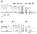
구성예 1은 평면에서 보아, 투과형 표시 소자(101)가 발광 소자(102)와 중첩되지 않는 영역을 갖는 예이다. 또한, 평면에서 보아, 발광 소자(102)는 투과형 표시 소자(101)와 중첩되지 않는 영역을 가져도 좋다.Configuration Example 1 is an example in which the
도 1의 (A)에 도시된 표시 패널(10)은 투과형 표시 소자(101) 및 발광 소자(102)를 갖는다. 투과형 표시 소자(101)의 일부는 발광 소자(102)와 중첩된다. 표시 패널(10)은 사용자(왼쪽 눈(31) 및 오른쪽 눈(32)) 측에 투과형 표시 소자(101)를 갖는다. 표시 패널(10)에는, 발광 소자(102) 측으로부터 외광(33)이 조사된다. 도 1의 (A)에서는, 발광 소자(102)로서 편면 발광 소자를 사용하는 경우를 도시하였다. 따라서, 외광(33)은 발광 소자(102)를 투과하지 않는다.The
표시 패널(10)은 투과형 표시 소자(101)를 통하여 외광(33)을 투과시킬 수 있다. 외광이 강한 경우, 표시 패널(10)에서는 투과형 표시 소자(101)를 사용하여 표시시키는 것이 바람직하다.The
외광(33)이 약한 경우, 표시 패널(10)에서는 발광 소자(102)를 사용하여 표시시키는 것이 바람직하다. 발광 소자(102)와 사용자 사이에는, 투과형 표시 소자(101)가 배치된다. 따라서, 발광 소자(102)를 사용하여 표시시킬 때 투과형 표시 소자(101)는 투과 상태로 한다. 발광 소자(102)로부터의 발광(34)은 투과형 표시 소자(101)를 통하여 추출된다.When the
도 1의 (B)에서는 발광 소자(102)로서 유기 EL 소자를 사용하는 경우를 도시하였다. 유기 EL 소자는 한 쌍의 전극 사이에 발광성 유기 화합물을 포함한 층(113)(EL층)을 갖는다. 도 1의 (B)에서, 사용자 측에 있는 전극인 제 1 전극(111)은 가시광을 투과시킨다.1B shows a case where an organic EL element is used as the
발광 소자(102)는 양면 발광 소자라도 좋다. 도 1의 (B)에서, 제 1 전극(111)과 대향하는 제 2 전극(115)이 가시광을 투과시켜도 좋다.The
발광 소자(102)가 양면 발광 소자인 경우, 투과형 표시 소자(101a) 중 발광 소자(102)와 중첩되는 영역에도 외광(33)이 발광 소자(102)를 통하여 입사한다. 따라서, 투과형 표시 소자(101a)의 상기 영역도 표시를 위하여 사용될 수 있어 바람직하다. 이로써, 투과 상태의 투과형 표시 소자와 불투과 상태의 투과형 표시 소자의 콘트라스트 차이가 커져, 표시 패널에서는 투과형 표시 소자를 사용하여 시인성이 더 높은 표시를 할 수 있다.When the
구성예 1과 같이, 평면에서 보아, 투과형 표시 소자(101)가 발광 소자(102)와 중첩되지 않는 영역을 갖는 경우, 발광 소자(102)는 편면 발광 소자라도 좋다. 도 1의 (B)에서, 제 1 전극(111)과 대향하는 제 2 전극(115)은 가시광을 투과시키지 않아도 좋다. 제 2 전극(115)으로서 가시광을 반사하는 전극을 사용하면 빛의 추출 효율이 높아져 바람직하다. 이로써, 발광 상태의 발광 소자와 비발광 상태의 발광 소자의 콘트라스트 차이가 커져, 표시 패널에서는 발광 소자를 사용하여 시인성이 더 높은 표시를 할 수 있다.In the case where the
도 1의 (B)에서는 투과형 표시 소자로서, 투과 상태이며 불투과의 부분을 갖지 않는 투과형 표시 소자(101a)를 사용하는 예를 도시하였다. 투과형 표시 소자(101a)로서는, 일렉트로크로믹 소자를 사용하는 것이 바람직하다. 일렉트로크로믹 소자는 투과 상태 및 불투과 상태 중 한쪽 상태로부터 다른 쪽 상태로 스위칭할 때에만 전압을 인가하면 좋고, 어느 쪽 상태를 유지하기 위하여 전압을 연속적으로 계속 인가할 필요는 없다. 따라서, 표시 패널의 소비 전력을 적게 할 수 있다. 또한, 일렉트로크로믹 소자는, 편광판이 불필요하다.1B shows an example in which the
도 1의 (C) 및 (D)에서는, 투과형 표시 소자로서, 투과 상태인 경우에도 불투과의 부분을 일부 갖는 투과형 표시 소자(101b)를 사용하는 예를 도시하였다. 투과형 표시 소자(101b)로서는, 예를 들어 일렉트로웨팅 소자를 들 수 있다.Figs. 1C and 1D show an example in which the
발광 소자(102)가 양면 발광 소자인 경우, 투과 상태이며 불투과의 부분을 갖지 않는 투과형 표시 소자(101a)에 비하여, 투과 상태인 경우에도 불투과의 부분을 일부 갖는 투과형 표시 소자(101b)는 투과시키는 외광량이 적다.In the case where the
발광 소자(102)가 편면 발광 소자이며 상기 불투과의 부분이 발광 소자(102)와 중첩되지 않는 경우(도 1의 (C) 참조), 투과형 표시 소자(101a)에 비하여 투과형 표시 소자(101b)는 투과시키는 외광량이 적다.The
발광 소자(102)가 편면 발광 소자이며 상기 불투과의 부분이 발광 소자(102)와 중첩되는 경우(도 1의 (D) 참조), 투과형 표시 소자(101a)와 투과형 표시 소자(101b)는 투과시키는 외광량이 동등하다. 그러나, 투과형 표시 소자(101a)를 사용하는 경우에 비하여 투과형 표시 소자(101b)를 사용하는 경우에는 발광 상태인 발광 소자(102)로부터 추출되는 광량이 적다.The
투과형 표시 소자를 통하여 투과하는 외광량이 많을수록, 투과형 표시 소자에서는 투과 상태와 불투과 상태의 콘트라스트 차이가 커진다. 발광 소자로부터 추출되는 광량이 많을수록 발광 소자에서는 발광 상태와 비발광 상태의 콘트라스트 차이가 커진다. 그러므로, 구성예 1의 투과형 표시 소자(101)에는 투과 상태이며 불투과의 부분을 갖지 않는 투과형 표시 소자(101a)를 적용하는 것이 바람직하다.The larger the amount of external light transmitted through the transmissive display element, the larger the contrast difference between the transmissive state and the non-transmissive state is in the transmissive display element. The greater the amount of light extracted from the light emitting element, the greater the contrast difference between the light emitting state and the non-light emitting state in the light emitting element. Therefore, it is preferable to apply the
또한, 구성예 1에서, 표시에 투과형 표시 소자(101)를 사용하는 경우에 발광 소자(102)의 구동 상태는 불문한다. 발광 소자(102)를 발광 상태로 하여 투과형 표시 소자를 투과하는 광량을 증가시켜도 좋다. 양면 발광 소자를 사용하는 경우, 비발광 상태로 함으로써 사용자가 전방의 풍경을 시인하기 쉽게 된다.In the configuration example 1, the driving state of the
<구성예 2>≪ Configuration Example 2 &
구성예 2는 평면에서 보아, 투과형 표시 소자(101)가 발광 소자(102)와 중첩되지 않는 영역을 갖는 예이다. 또한, 평면에서 보아, 발광 소자(102)는 투과형 표시 소자(101)와 중첩되지 않는 영역을 가져도 좋다.The configuration example 2 is an example in which the
도 2의 (A)에 도시된 표시 패널(12)은 투과형 표시 소자(101) 및 발광 소자(102)를 갖는다. 투과형 표시 소자(101)의 일부는 발광 소자(102)와 중첩된다. 표시 패널(12)은 사용자(왼쪽 눈(31) 및 오른쪽 눈(32)) 측에 발광 소자(102)를 갖는다. 표시 패널(12)에는, 투과형 표시 소자(101) 측으로부터 외광(33)이 조사된다. 도 2의 (A)에서는, 발광 소자(102)로서 편면 발광 소자를 사용하는 경우를 도시하였다. 따라서, 외광(33)은 발광 소자(102)를 투과하지 않는다.The
표시 패널(12)은 투과형 표시 소자(101)를 통하여 외광(33)을 투과시킬 수 있다. 외광이 강한 경우, 표시 패널(12)에서는 투과형 표시 소자(101)를 사용하여 표시시키는 것이 바람직하다.The
외광(33)이 약한 경우, 표시 패널(12)에서는 발광 소자(102)를 사용하여 표시시키는 것이 바람직하다.In the case where the
도 2의 (B)에는 발광 소자(102)로서 유기 EL 소자를 사용하는 경우를 도시하였다. 도 2의 (B)에서, 사용자 측에 있는 전극인 제 1 전극(111)은 가시광을 투과시킨다.2B shows a case where an organic EL element is used as the
발광 소자(102)는 양면 발광 소자라도 좋다. 도 2의 (B)에서, 제 1 전극(111)과 대향하는 제 2 전극(115)은 가시광을 투과시켜도 좋다.The
발광 소자(102)가 양면 발광 소자인 경우, 표시 패널(12)은 투과형 표시 소자(101a) 중 발광 소자(102)와 중첩되는 영역에서도 외광(33)을 투과시킬 수 있다. 따라서, 상기 영역도 투과형 표시 소자(101a)를 사용한 표시를 위하여 사용될 수 있어 바람직하다. 이로써, 투과 상태의 투과형 표시 소자와 불투과 상태의 투과형 표시 소자의 콘트라스트 차이가 커져, 표시 패널에서는 투과형 표시 소자를 사용하여 시인성이 더 높은 표시를 할 수 있다.When the
구성예 2도 구성예 1과 마찬가지로 발광 소자(102)가 편면 발광 소자라도 좋고, 자세하게는 구성예 1의 기재를 참조할 수 있다.Configuration Example 2 Similarly to Configuration Example 1, the
도 2의 (B)에서는 투과형 표시 소자로서, 투과 상태이며 불투과의 부분을 갖지 않는 투과형 표시 소자(101a)를 사용하는 예를 도시하였다. 도 2의 (C) 및 (D)에서는, 투과형 표시 소자로서, 투과 상태인 경우에도 불투과의 부분을 일부 갖는 투과형 표시 소자(101b)를 사용하는 예를 도시하였다.2B shows an example in which a
발광 소자(102)가 양면 발광 소자인 경우, 투과 상태이며 불투과의 부분을 갖지 않는 투과형 표시 소자(101a)에 비하여 투과형 표시 소자(101b)는 투과시키는 외광량이 적다.When the
발광 소자(102)가 편면 발광 소자이며 상기 불투과의 부분이 발광 소자(102)와 중첩되지 않는 경우(도 2의 (C) 참조), 투과형 표시 소자(101a)에 비하여 투과형 표시 소자(101b)는 투과시키는 외광량이 적다.When the
발광 소자(102)가 편면 발광 소자이며 상기 불투과의 부분이 발광 소자(102)와 중첩되는 경우(도 2의 (D) 참조), 투과형 표시 소자(101a)와 투과형 표시 소자(101b)는 투과시키는 외광량이 동등하다.The
또한, 발광 상태인 발광 소자(102)로부터 추출되는 광량은 투과 상태인 투과형 표시 소자의 불투과의 부분의 유무나 위치에는 관계없다.Further, the amount of light extracted from the
따라서, 구성예 2의 투과형 표시 소자(101)에는 투과 상태이며 불투과의 부분을 갖지 않는 투과형 표시 소자(101a)를 적용하는 것이 바람직하다. 그리고, 발광 소자(102)가 편면 발광 소자인 경우에는, 도 2의 (D)에 도시된 바와 같이 투과형 표시 소자(101b)의 불투과의 부분이 발광 소자(102)와 중첩되는 구성도 바람직하다.Therefore, it is preferable to apply the
또한, 구성예 2에서, 표시에 투과형 표시 소자(101)를 사용하는 경우, 발광 소자(102)는 비발광 상태인 것이 바람직하다. 그러므로, 투과형 표시 소자(101)를 사용한 표시는, 사용자에게 시인하기 쉽게 된다.In the configuration example 2, when the
<구성예 3>≪ Configuration Example 3 &
구성예 3은 평면에서 보아, 투과형 표시 소자(101)와 발광 소자(102)가 중첩되지 않는 예이다.Configuration Example 3 is an example in which the
도 2의 (E)에 도시된 표시 패널(13)은 투과형 표시 소자(101) 및 발광 소자(102)를 갖는다. 표시 패널(13)은 투과형 표시 소자(101)를 통하여 외광(33)을 투과시킬 수 있다. 외광(33)이 강한 경우, 표시 패널(13)에서는 투과형 표시 소자(101)를 사용하여 표시시키는 것이 바람직하다. 외광(33)이 약한 경우, 표시 패널(13)에서는 발광 소자(102)를 사용하여 표시시키는 것이 바람직하다.The
도 2의 (E)에 도시된 바와 같이, 표시 패널(13)에서는 사용자 측과 반대 측에 있는 전극이 가시광을 반사하는 편면 발광 소자를 발광 소자(102)로서 사용하여도 좋다. 이로써, 발광 상태의 발광 소자와 비발광 상태의 발광 소자의 콘트라스트 차이가 커져, 표시 패널에서는 발광 소자를 사용하여 시인성이 더 높은 표시를 할 수 있다. 투과형 표시 소자(101)를 사용하여 표시시키는 동안에 발광 소자(102)를 비발광 상태로 하는 것이 바람직하다. 그러므로, 투과형 표시 소자(101)를 사용한 표시는, 사용자에게 시인하기 쉽게 된다.As shown in FIG. 2 (E), the
표시 패널(13)에서는, 발광 소자(102)로서 양면 발광 소자를 사용하여도 좋다. 투과형 표시 소자(101)를 사용하여 표시시키는 동안에 발광 소자(102)를 비발광 상태로 함으로써, 사용자는 발광 소자(102)를 통하여 전방의 풍경을 시인할 수 있다.In the
투과형 표시 소자(101)로서, 투과 상태에서 불투과의 부분을 갖지 않는 투과형 표시 소자를 사용하면, 불투과의 부분을 갖는 소자에 비하여 투과 상태의 투과형 표시 소자(101)를 통하여 투과되는 외광량이 많기 때문에 바람직하다. 발광 소자(102)를 사용하여 표시시키는 동안에 투과형 표시 소자(101)의 상태는 불문한다(투과 상태라도 불투과 상태라도 좋다).When the transmissive display element having no transmissive portion in the transmissive state is used as the
<구성예 4>≪ Configuration Example 4 &
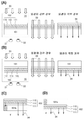
구성예 4는 평면에서 보아, 투과형 표시 소자(101) 전체가 발광 소자(102)와 중첩되는 예이다. 또한, 평면에서 보아, 발광 소자(102)는 투과형 표시 소자(101)와 중첩되지 않는 영역을 가져도 좋다.The configuration example 4 is an example in which the entire
도 3의 (A)에 도시된 표시 패널(14)은 투과형 표시 소자(101) 및 발광 소자(102)를 갖는다. 표시 패널(14)은 사용자(왼쪽 눈(31) 및 오른쪽 눈(32)) 측에 투과형 표시 소자(101)를 갖는다. 표시 패널(14)에는, 발광 소자(102) 측으로부터 외광(33)이 조사된다.The
표시 패널(14)이 갖는 발광 소자(102)는 양면 발광 소자이다. 사용자 측에 있는 전극인 제 1 전극(111), 및 제 1 전극(111)과 대향하는 제 2 전극(115)은 각각 가시광을 투과시킨다.The
발광 소자(102)가 양면 발광 소자이므로, 투과형 표시 소자(101)에는 외광(33)이 발광 소자(102)를 통하여 입사한다. 외광이 강한 경우, 표시 패널(14)에서는 투과형 표시 소자(101)를 사용하여 표시시키는 것이 바람직하다.Since the
외광(33)이 약한 경우, 표시 패널(14)에서는 발광 소자(102)를 사용하여 표시시키는 것이 바람직하다. 발광 소자(102)와 사용자 사이에는, 투과형 표시 소자(101)가 배치된다. 따라서, 발광 소자(102)를 사용하여 표시시킬 때 투과형 표시 소자(101)는 투과 상태로 한다. 발광 소자(102)로부터의 발광(34)은 투과형 표시 소자(101)를 통하여 추출된다.When the
또한, 구성예 4에서, 표시에 투과형 표시 소자(101)를 사용하는 경우에 발광 소자(102)의 구동 상태는 불문한다. 발광 소자(102)를 발광 상태로 하여 투과형 표시 소자를 투과하는 광량을 증가시켜도 좋다. 양면 발광 소자를 사용하는 경우, 비발광 상태로 함으로써 사용자는 전방의 풍경을 시인하기 쉽게 된다.In the configuration example 4, the driving state of the
<구성예 5>≪ Configuration Example 5 &
구성예 5는 평면에서 보아, 투과형 표시 소자(101) 전체가 발광 소자(102)와 중첩되는 예이다. 또한, 평면에서 보아, 발광 소자(102)는 투과형 표시 소자(101)와 중첩되지 않는 영역을 가져도 좋다.The configuration example 5 is an example in which the entire
도 3의 (B)에 도시된 표시 패널(16)은 투과형 표시 소자(101) 및 발광 소자(102)를 갖는다. 표시 패널(16)은 사용자(왼쪽 눈(31) 및 오른쪽 눈(32)) 측에 발광 소자(102)를 갖는다. 표시 패널(16)에는, 투과형 표시 소자(101) 측으로부터 외광(33)이 조사된다.The
표시 패널(16)은 투과형 표시 소자(101)를 통하여 외광(33)을 투과시킬 수 있다. 외광이 강한 경우, 표시 패널(16)에서는 투과형 표시 소자(101)를 사용하여 표시시키는 것이 바람직하다. 이 때, 발광 소자(102)는 비발광 상태로 한다.The
외광이 약한 경우, 표시 패널(16)에서는 발광 소자(102)를 사용하여 표시시키는 것이 바람직하다. 이 때, 투과형 표시 소자(101)의 상태는 불문한다(투과 상태라도 불투과 상태라도 좋다).When the external light is weak, it is preferable to display the
표시 패널(16)이 갖는 발광 소자(102)는 양면 발광 소자이다. 사용자 측에 있는 전극인 제 1 전극(111), 및 제 1 전극(111)과 대향하는 제 2 전극(115)은 각각 가시광을 투과시킨다.The
구성예 4에 투과형 표시 소자(101b)를 적용한 예를 도 3의 (C)에 도시하였고, 구성예 5에 투과형 표시 소자(101b)를 적용한 예를 도 3의 (D)에 도시하였다. 도 3의 (C) 및 (D)에 도시된 바와 같이, 구성예 5는 구성예 4에 비하여 발광 상태의 발광 소자(102)로부터 추출되는 광량이 많아 바람직하다.An example in which the
구성예 4 및 구성예 5에서는, 투과형 표시 소자로서 사용할 수 있는 소자에 한정은 없다. 그러나, 상술한 바와 같이, 표시 패널에 투과형 표시 소자(101b)를 사용하는 경우에는 구성예 5를 적용하는 것이 바람직하다.In Configuration Example 4 and Configuration Example 5, there is no limitation to an element that can be used as a transmissive display element. However, as described above, it is preferable to apply the configuration example 5 when the
<평면 레이아웃><Flat layout>
이하에서는, 평면에서 보아, 투과형 표시 소자(101) 및 발광 소자(102) 중 한쪽이 다른 쪽과 중첩되지 않는 영역을 갖는 경우의 평면 레이아웃의 일례에 대하여 설명한다. 또한, 도 4에서는 하나의 화소를 2점 쇄선으로 둘러싸 도시하였다.Hereinafter, an example of a planar layout in a case where one of the
표시 패널은 투과형 표시 소자 하나에 대하여 발광 소자를 하나 가져도 좋고, 2개 이상 가져도 좋다. 발광 소자로 구성되는 화소수와, 투과형 표시 소자로 구성되는 화소수는 동일하여도 상이하여도 좋다.The display panel may have one light emitting element or two or more light emitting elements per transmissive display element. The number of pixels constituted by the light emitting element and the number of pixels constituted by the transmissive display element may be the same or different.
평면에서 보아, 투과형 표시 소자(101)나 발광 소자(102)의 형상은 불문한다. 예를 들어, 도 4에서는 직사각형으로 하여 도시하였으나, 이 외의 사각형이라도 좋고, 사각형 외의 다각형이라도 좋고, 원형이라도 좋다.The shape of the
도 4의 (A)에서는, 하나의 발광 소자(102)에 대하여 하나의 투과형 표시 소자(101)를 갖는 예를 도시하였다. 투과형 표시 소자(101)를 사용한 표시 및 발광 소자(102)를 사용한 표시는 어느 쪽도 단색 표시이다.FIG. 4A shows an example in which one
도 4의 (A)에서, 하나의 화소는 하나의 발광 소자(102) 또는 하나의 투과형 표시 소자(101)를 갖는다. 표시 패널은, 발광 소자를 사용하여도 투과형 표시 소자를 사용하여도, 동등한 해상도를 가진 화상 등을 표시할 수 있다.In Fig. 4 (A), one pixel has one
도 4의 (B)에서는, 3개의 발광 소자(102)에 대하여 하나의 투과형 표시 소자(101)를 갖는 예를 도시하였다. 투과형 표시 소자(101)를 사용한 표시는 단색 표시이다. 발광 소자는, 구분 착색 방식이나 컬러 필터 방식 등으로 적색의 발광 소자(102)(R), 녹색의 발광 소자(102)(G), 청색의 발광 소자(102)(B)로 나누어져 있다. 발광 소자를 사용한 표시는 풀컬러 표시이다.Fig. 4B shows an example in which one
도 4의 (B)에서, 하나의 화소는 3개의 발광 소자(102) 또는 하나의 투과형 표시 소자(101)를 갖는다. 표시 패널은 발광 소자를 사용하여도 투과형 표시 소자를 사용하여도, 동등한 해상도를 가진 화상 등을 표시할 수 있다.In Fig. 4 (B), one pixel has three light emitting
도 4의 (C)에서는, 투과형 표시 소자도 컬러 필터 방식 등으로 적색의 투과형 표시 소자(101)(R), 녹색의 투과형 표시 소자(101)(G), 청색의 투과형 표시 소자(101)(B)로 나누어져 있다. 투과형 표시 소자를 사용한 표시는 풀컬러 표시이다. 발광 소자의 구성은 도 4의 (B)와 마찬가지이다.4C, a transmissive display element 101 (R), a green transmissive display element 101 (G), and a blue transmissive display element 101 (red B). The display using the transmissive display element is a full color display. The configuration of the light emitting element is the same as that of FIG. 4 (B).
도 4의 (C)에서는, 하나의 화소는 3개의 발광 소자(102) 또는 3개의 투과형 표시 소자(101)를 갖는다. 표시 패널은 발광 소자를 사용하여도 투과형 표시 소자를 사용하여도, 동등한 해상도를 가진 풀컬러의 화상 등을 표시할 수 있다.In Fig. 4C, one pixel has three light-emitting
도 4의 (D)에서는, 3개의 발광 소자에 대하여 하나의 투과형 표시 소자를 갖는 예를 도시하였다. 하나의 화소는 3개의 발광 소자 또는 하나의 투과형 표시 소자로 구성된다. 도 4의 (D)에서, 투과형 표시 소자를 사용한 표시는 발광 소자를 사용한 표시에 비하여 해상도가 높다.FIG. 4D shows an example in which one transmissive display element is provided for three light emitting elements. One pixel is composed of three light emitting elements or one transmissive display element. In (D) of FIG. 4, the display using the transmissive display element has a higher resolution than the display using the light emitting element.
도 4의 (E)에서는, 2개의 발광 소자에 대하여 하나의 투과형 표시 소자를 갖는 예를 도시하였다. 하나의 화소는 3개의 발광 소자 또는 하나의 투과형 표시 소자로 구성된다.4E shows an example in which one transmissive display element is provided for two light emitting elements. One pixel is composed of three light emitting elements or one transmissive display element.
본 실시형태는 다른 실시형태와 적절히 조합할 수 있다.This embodiment can be combined with other embodiments as appropriate.
(실시형태 2)(Embodiment 2)
본 실시형태에서는 본 발명의 일 형태인 표시 장치에 대하여 도 5를 사용하여 설명한다. 본 발명의 일 형태인 표시 장치는 실시형태 1에서 설명한 표시 패널을 갖는다. 따라서, 사용자는 주위의 밝기에 의존하지 않고 표시 장치의 표시를 충분히 시인할 수 있다.In this embodiment, a display device which is one embodiment of the present invention will be described with reference to Fig. The display device according to one embodiment of the present invention has the display panel described in the first embodiment. Therefore, the user can sufficiently visually recognize the display of the display device without depending on the brightness of the surroundings.
<구성예 1><Configuration Example 1>
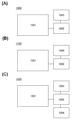
본 발명의 일 형태는 주위의 밝기에 따라 표시를 위하여 사용하는 소자가 선택되는 표시 장치이다. 본 발명의 일 형태인 표시 장치는 표시 패널과, 주위의 밝기를 측정하는 조도 센서와, 상기 조도 센서의 측정 결과에 따라 상기 표시 패널의 표시를 스위칭하는 제어 회로를 갖는다. 이하에서는, 외광이 조사되는 수광 소자를 갖는 표시 장치를 예로 들어 설명한다.One embodiment of the present invention is a display device in which elements used for display are selected according to ambient brightness. A display device according to one aspect of the present invention includes a display panel, a brightness sensor for measuring the brightness of the surroundings, and a control circuit for switching the display of the display panel according to the measurement result of the brightness sensor. Hereinafter, a display device having a light receiving element to which external light is irradiated will be described as an example.
도 5의 (A)에 도시된 표시 장치(1000)는 표시 패널(1001)과, 제어 회로(1002)와, 수광 소자(1003)를 갖는다.A
표시 패널(1001)에는 실시형태 1에서 설명한 표시 패널을 적용할 수 있다.The display panel described in Embodiment 1 can be applied to the
제어 회로(1002)는 표시 패널(1001)을 제어할 수 있다. 구체적으로는, 제어 회로(1002)는 표시 패널(1001)의 표시를 위하여 사용하는 소자를 스위칭한다(표시 패널(1001)에서, 투과형 표시 소자 및 발광 소자 중 어느 쪽을 사용하여 표시시킬지를 선택한다).The
수광 소자(1003)에는 외광이 조사된다. 수광 소자(1003)의 개수는 하나라도 복수라도 좋다. 하나의 수광 소자에는, 표시 패널(1001)의 표시면인 한쪽 면 측으로부터 조사되는 외광, 또는 상기 표시면과 대향하는 다른 쪽 면 측으로부터 조사되는 외광 중 적어도 한쪽의 외광이 조사되면 좋다. 표시 장치(1000)는, 하나 또는 복수의 수광 소자를 사용하여 양쪽 면 측으로부터 조사되는 외광의 광량을 측정할 수 있는 것이 바람직하다.The
도 5의 (A)에 도시된 표시 장치(1000)에서는, 수광 소자(1003)에 조사된 광량이 일정 값 이상인 경우, 투과형 표시 소자를 사용한 표시가 행해지고, 수광 소자에 조사된 광량이 일정 값 미만인 경우, 발광 소자를 사용한 표시가 행해지도록 제어 회로(1002)가 표시 패널(1001)을 제어할 수 있다.In the
<구성예 2>≪ Configuration Example 2 &
본 발명의 일 형태는, 표시를 위하여 사용하는 소자를 사용자가 정할 수 있는 표시 장치이다. 본 발명의 일 형태인 표시 장치는 표시 패널과, 스위치와, 상기 스위치의 상태에 따라 상기 표시 패널의 표시를 스위칭하는 제어 회로를 갖는다.An aspect of the present invention is a display device in which a user can specify an element to be used for display. A display device according to one aspect of the present invention includes a display panel, a switch, and a control circuit for switching the display of the display panel according to the state of the switch.
도 5의 (B)에 도시된 표시 장치(1100)는 표시 패널(1001)과, 제어 회로(1002)와, 스위치(1004)를 갖는다.A
표시 패널(1001)에는 실시형태 1에서 설명한 표시 패널을 적용할 수 있다.The display panel described in Embodiment 1 can be applied to the
제어 회로(1002)는 표시 패널(1001)을 제어할 수 있다. 구체적으로는 표시 패널(1001)의 표시를 위하여 사용하는 소자를 스위칭한다(투과형 표시 소자 및 발광 소자 중 어느 쪽을 사용하여 표시시킬지를 선택한다).The
스위치(1004)는 적어도 제 1 상태 및 제 2 상태를 갖고, 스위치(1004)의 상태는 표시 장치의 사용자가 스위칭시킬 수 있다.The
예를 들어, 도 5의 (B)에 도시된 표시 장치(1100)에서는, 스위치(1004)가 제 1 상태인 경우에 투과형 표시 소자를 사용한 표시가 행해지고 스위치(1004)가 제 2 상태인 경우에 발광 소자를 사용한 표시가 행해지도록, 제어 회로(1002)가 표시 패널(1001)을 제어하여도 좋다.For example, in the
또는, 도 5의 (B)에 도시된 표시 장치(1100)에서는, 스위치(1004)의 상태가 스위칭되었을 때 표시 패널(1001)에서도 표시를 위하여 사용하는 소자가 스위칭되도록, 제어 회로(1002)가 표시 패널(1001)을 제어하여도 좋다. 예를 들어, 표시 장치(1100)는, 표시 장치(1100)의 사용 시작 시(전원을 켰을 때)에 표시 패널(1001)에서 표시를 위하여 사용하는 소자가 발광 소자 및 투과형 표시 소자 중 어느 한쪽으로 정해져 있고, 사용 중에 스위치(1004)의 상태가 스위칭됨으로써 표시 패널(1001)에서 표시를 위하여 사용하는 소자를 스위칭할 수 있는 사양이라도 좋다.Alternatively, in the
<구성예 3>≪ Configuration Example 3 &
본 발명의 일 형태는, 표시 장치의 주위의 밝기에 따라 표시를 위하여 사용하는 소자가 선택되며 표시를 위하여 사용하는 소자를 사용자가 정할 수도 있는 표시 장치이다. 본 발명의 일 형태인 표시 장치는 표시 패널과, 스위치와, 표시 장치의 주위의 밝기를 측정하는 조도 센서와, 상기 조도 센서의 측정 결과나 상기 스위치의 상태에 따라 상기 표시 패널의 표시를 스위칭하는 제어 회로를 갖는다.An aspect of the present invention is a display device in which a device to be used for display is selected in accordance with the brightness of the surroundings of the display device, and a user may define a device to be used for display. A display device according to one aspect of the present invention includes a display panel, a switch, an illuminance sensor for measuring the brightness of the surroundings of the display device, and a switch for switching the display of the display panel according to the measurement result of the illuminance sensor and the state of the switch And a control circuit.
도 5의 (C)에 도시된 표시 장치(1200)는 표시 패널(1001)과, 제어 회로(1002)와, 수광 소자(1003)와, 스위치(1004)를 갖는다.A
표시 패널(1001)에는 실시형태 1에서 설명한 표시 패널을 적용할 수 있다.The display panel described in Embodiment 1 can be applied to the
수광 소자(1003)에는 구성예 1과 같은 수광 소자를 적용할 수 있다.The light-receiving
제어 회로(1002)는 표시 패널(1001)을 제어할 수 있다. 구체적으로는 표시 패널(1001)의 표시를 위하여 사용하는 소자를 스위칭한다(투과형 표시 소자 및 발광 소자 중 어느 쪽을 사용하여 표시시킬지를 선택한다).The
스위치(1004)는 적어도 제 1 상태 및 제 2 상태를 갖고, 스위치의 상태는 표시 장치의 사용자가 스위칭시킬 수 있다.The
예를 들어, 도 5의 (C)에 도시된 표시 장치(1200)에서는, 수광 소자(1003)에 조사된 광량이 일정 값 이상인 경우, 투과형 표시 소자를 사용한 표시가 행해지고 수광 소자에 조사된 광량이 일정 값 미만인 경우, 발광 소자를 사용한 표시가 행해지도록 제어 회로(1002)가 표시 패널(1001)을 제어할 수 있다.For example, in the
또한 표시 장치(1200)에서는, 스위치(1004)의 상태가 스위칭되었을 때 표시 패널(1001)에서도 표시를 위하여 사용하는 소자가 스위칭되도록 제어 회로(1002)가 표시 패널(1001)을 제어할 수 있다.In the
표시 장치(1200)는 예를 들어 일반적으로는 수광 소자(1003)에 조사된 광량에 따라 표시 패널(1001)의 표시를 위하여 사용하는 소자가 스위칭되고, 사용자가 스위치(1004)의 상태를 스위칭시킴으로써 표시 패널(1001)에서 표시를 위하여 사용하는 소자를 강제적으로 스위칭할 수 있는 사양이라도 좋다.In the
또는, 도 5의 (C)에 도시된 표시 장치(1200)에서는, 스위치가 제 1 상태인 경우, 투과형 표시 소자를 사용한 표시가 행해지고, 스위치가 제 2 상태인 경우, 발광 소자를 사용한 표시가 행해지고, 스위치가 제 3 상태인 경우, 수광 소자(1003)에 조사된 광량에 따라 표시 패널(1001)의 표시를 위하여 사용하는 소자가 정해지도록 제어 회로(1002)가 표시 패널(1001)을 제어할 수 있는 사양이라도 좋다.Alternatively, in the
본 실시형태는 다른 실시형태와 적절히 조합할 수 있다.This embodiment can be combined with other embodiments as appropriate.
10: 표시 패널
12: 표시 패널
13: 표시 패널
14: 표시 패널
16: 표시 패널
31: 왼쪽 눈
32: 오른쪽 눈
33: 외광
34: 발광
101: 투과형 표시 소자
101a: 투과형 표시 소자
101b: 투과형 표시 소자
102: 발광 소자
111: 제 1 전극
113: 발광성 유기 화합물을 포함한 층
115: 제 2 전극
1000: 표시 장치
1001: 표시 패널
1002: 제어 회로
1003: 수광 소자
1004: 스위치
1100: 표시 장치
1200: 표시 장치10: Display panel
12: Display panel
13: Display panel
14: Display panel
16: Display panel
31: Left eye
32: Right eye
33: External light
34: Light emission
101: Transmissive display element
101a: transmissive display element
101b: transmissive display element
102: Light emitting element
111: first electrode
113: Layer containing a luminous organic compound
115: second electrode
1000: display device
1001: Display panel
1002: Control circuit
1003: Light receiving element
1004: Switch
1100: Display device
1200: display device
Claims (13)
외광을 투과시킬 수 있는 표시 패널로서,
투과형 표시 소자와;
가시광을 투과시킬 수 있는 제 1 전극과, 제 2 전극과, 상기 제 1 전극과 상기 제 2 전극 사이의 EL층을 포함하고, 상기 투과형 표시 소자와 중첩되는 발광 소자를 포함하는 상기 표시 패널을 포함하고,
상기 투과형 표시 소자 및 상기 발광 소자는 서로 중첩되고,
상기 투과형 표시 소자는 상기 발광 소자와 중첩되는 제 1 영역과, 상기 제 1 전극, 상기 제 2 전극, 및 상기 EL층의 어느 것과도 중첩되지 않는 제 2 영역을 포함하는, 표시 장치.In the display device,
A display panel capable of transmitting external light,
A transmissive display element;
The display panel including a first electrode capable of transmitting visible light, a second electrode, and a light-emitting element including an EL layer between the first electrode and the second electrode and overlapping with the transmissive display element and,
The transmissive display element and the light emitting element overlap each other,
The transmissive display element includes a first region overlapping with the light emitting element and a second region not overlapping with any of the first electrode, the second electrode, and the EL layer.
상기 제 2 전극은 가시광을 반사시킬 수 있는, 표시 장치.The method according to claim 1,
Wherein the second electrode is capable of reflecting visible light.
상기 투과형 표시 소자는 불투과의 부분을 포함하는, 표시 장치.The method according to claim 1,
Wherein the transmissive display element includes a non-transmissive portion.
상기 투과형 표시 소자는 일렉트로크로믹 소자인, 표시 장치.The method according to claim 1,
Wherein the transmissive display element is an electrochromic element.
상기 투과형 표시 소자는 일렉트로웨팅 소자인, 표시 장치.The method according to claim 1,
Wherein the transmissive display element is an electrowetting element.
상기 투과형 표시 소자는 액정 소자인, 표시 장치.The method according to claim 1,
Wherein the transmissive display element is a liquid crystal element.
제어 회로와;
수광(受光) 소자를 더 포함하고,
상기 제어 회로는 상기 수광 소자에 따라서 상기 표시 패널에서의 표시를 제어하는, 표시 장치.The method according to claim 1,
A control circuit;
Further comprising a light receiving element,
And the control circuit controls display on the display panel in accordance with the light receiving element.
외광을 투과시킬 수 있는 표시 패널로서,
투과형 표시 소자와;
가시광을 투과시킬 수 있는 제 1 전극과, 가시광을 투과시킬 수 있는 제 2 전극과, 상기 제 1 전극과 상기 제 2 전극 사이의 EL층을 포함하는 발광 소자를 포함하는 상기 표시 패널을 포함하고,
상기 투과형 표시 소자 및 상기 발광 소자는 나란히 위치되는, 표시 장치.In the display device,
A display panel capable of transmitting external light,
A transmissive display element;
The display panel including a first electrode capable of transmitting visible light, a second electrode capable of transmitting visible light, and a light emitting element including an EL layer between the first electrode and the second electrode,
And the transmissive display element and the light emitting element are positioned side by side.
상기 투과형 표시 소자는 불투과의 부분을 포함하는, 표시 장치.9. The method of claim 8,
Wherein the transmissive display element includes a non-transmissive portion.
상기 투과형 표시 소자는 일렉트로크로믹 소자인, 표시 장치.9. The method of claim 8,
Wherein the transmissive display element is an electrochromic element.
상기 투과형 표시 소자는 일렉트로웨팅 소자인, 표시 장치.9. The method of claim 8,
Wherein the transmissive display element is an electrowetting element.
상기 투과형 표시 소자는 액정 소자인, 표시 장치.9. The method of claim 8,
Wherein the transmissive display element is a liquid crystal element.
제어 회로와;
수광 소자를 더 포함하고,
상기 제어 회로는 상기 수광 소자에 따라서 상기 표시 패널에서의 표시를 제어하는, 표시 장치.9. The method of claim 8,
A control circuit;
Further comprising a light receiving element,
And the control circuit controls display on the display panel in accordance with the light receiving element.
Applications Claiming Priority (2)
| Application Number | Priority Date | Filing Date | Title |
|---|---|---|---|
| JP2013066119 | 2013-03-27 | ||
| JPJP-P-2013-066119 | 2013-03-27 |
Publications (1)
| Publication Number | Publication Date |
|---|---|
| KR20140118770A true KR20140118770A (en) | 2014-10-08 |
Family
ID=51620520
Family Applications (1)
| Application Number | Title | Priority Date | Filing Date |
|---|---|---|---|
| KR1020140030430A KR20140118770A (en) | 2013-03-27 | 2014-03-14 | Display device |
Country Status (3)
| Country | Link |
|---|---|
| US (1) | US9715103B2 (en) |
| JP (2) | JP2014209214A (en) |
| KR (1) | KR20140118770A (en) |
Families Citing this family (12)
| Publication number | Priority date | Publication date | Assignee | Title |
|---|---|---|---|---|
| KR102028732B1 (en) | 2012-04-05 | 2019-10-04 | 매직 립, 인코포레이티드 | Wide-field of view (fov) imaging devices with active foveation capability |
| KR102338907B1 (en) * | 2015-02-13 | 2021-12-14 | 삼성디스플레이 주식회사 | Liquid crystal display apparatus and method for manufacturing the same |
| EP3310607A4 (en) * | 2015-06-22 | 2019-02-27 | Continental Automotive GmbH | Transparent display with a controllable masking display |
| WO2017064593A1 (en) | 2015-10-12 | 2017-04-20 | Semiconductor Energy Laboratory Co., Ltd. | Display device and manufacturing method thereof |
| WO2017081575A1 (en) | 2015-11-11 | 2017-05-18 | Semiconductor Energy Laboratory Co., Ltd. | Display device and method for manufacturing the same |
| JP6799956B2 (en) * | 2016-07-14 | 2020-12-16 | 株式会社半導体エネルギー研究所 | Display devices, display modules and electronic devices |
| KR101861309B1 (en) * | 2017-04-26 | 2018-07-05 | 경희대학교 산학협력단 | Hybrid display device |
| KR101931619B1 (en) * | 2017-04-26 | 2019-03-13 | 경희대학교 산학협력단 | Hybrid display device |
| CN107230699A (en) * | 2017-06-05 | 2017-10-03 | 京东方科技集团股份有限公司 | A kind of display panel, display device and its driving method |
| RU2748961C1 (en) * | 2017-12-07 | 2021-06-02 | Боэ Текнолоджи Груп Ко., Лтд. | Display panel having light modulation area, display device, method for modulating the display panel display contrast and method for display panel manufacturing |
| WO2021070236A1 (en) * | 2019-10-08 | 2021-04-15 | シャープ株式会社 | Light-emitting device |
| CN112835205B (en) * | 2019-11-25 | 2023-04-07 | 苏州苏大维格科技集团股份有限公司 | Three-dimensional display device |
Family Cites Families (52)
| Publication number | Priority date | Publication date | Assignee | Title |
|---|---|---|---|---|
| JPS6160284U (en) * | 1984-09-21 | 1986-04-23 | ||
| JPS6434678U (en) * | 1987-08-27 | 1989-03-02 | ||
| JPH11202332A (en) * | 1997-11-11 | 1999-07-30 | Sumitomo Electric Ind Ltd | Display device |
| JP3767264B2 (en) | 1999-08-25 | 2006-04-19 | セイコーエプソン株式会社 | Liquid crystal display device and electronic device |
| WO2001091098A1 (en) | 2000-05-24 | 2001-11-29 | Hitachi, Ltd. | Color/black-and-white switchable portable terminal and display device |
| JP2002196702A (en) | 2000-12-25 | 2002-07-12 | Sony Corp | Image display device |
| TW544650B (en) | 2000-12-27 | 2003-08-01 | Matsushita Electric Ind Co Ltd | Matrix-type display device and driving method thereof |
| JP4202030B2 (en) | 2001-02-20 | 2008-12-24 | シャープ株式会社 | Display device |
| JP2002296375A (en) * | 2001-03-29 | 2002-10-09 | Seiko Epson Corp | Information display device, wristwatch, and portable information apparatus |
| JP3898012B2 (en) * | 2001-09-06 | 2007-03-28 | シャープ株式会社 | Display device |
| JP4043864B2 (en) | 2001-09-06 | 2008-02-06 | シャープ株式会社 | Display device and driving method thereof |
| JP4176400B2 (en) | 2001-09-06 | 2008-11-05 | シャープ株式会社 | Display device |
| JP4452075B2 (en) | 2001-09-07 | 2010-04-21 | パナソニック株式会社 | EL display panel, driving method thereof, and EL display device |
| EP1434193A4 (en) | 2001-09-07 | 2009-03-25 | Panasonic Corp | El display, el display driving circuit and image display |
| US7248235B2 (en) | 2001-09-14 | 2007-07-24 | Sharp Kabushiki Kaisha | Display, method of manufacturing the same, and method of driving the same |
| EP1450341A4 (en) | 2001-09-25 | 2009-04-01 | Panasonic Corp | El display panel and el display apparatus comprising it |
| JP2003098984A (en) * | 2001-09-25 | 2003-04-04 | Rohm Co Ltd | Image display device |
| US7064740B2 (en) | 2001-11-09 | 2006-06-20 | Sharp Laboratories Of America, Inc. | Backlit display with improved dynamic range |
| GB0129068D0 (en) | 2001-12-05 | 2002-01-23 | Koninl Philips Electronics Nv | Display device |
| JP2003228304A (en) | 2002-01-31 | 2003-08-15 | Toyota Industries Corp | Display device |
| TW544944B (en) * | 2002-04-16 | 2003-08-01 | Ind Tech Res Inst | Pixel element structure of sunlight-readable display |
| KR100638304B1 (en) | 2002-04-26 | 2006-10-26 | 도시바 마쯔시따 디스플레이 테크놀로지 컴퍼니, 리미티드 | Driver circuit of el display panel |
| CN100536347C (en) | 2002-04-26 | 2009-09-02 | 东芝松下显示技术有限公司 | Semiconductor circuit group for driving current-driven display device |
| JP4042516B2 (en) | 2002-04-26 | 2008-02-06 | カシオ計算機株式会社 | Display device |
| JP4122828B2 (en) | 2002-04-30 | 2008-07-23 | 日本電気株式会社 | Display device and driving method thereof |
| CN100386676C (en) * | 2002-04-30 | 2008-05-07 | 中佛罗里达大学 | Transflective liquid crystal display with partial switching |
| CN1662842B (en) | 2002-06-20 | 2010-05-12 | 夏普株式会社 | Display |
| JP2004045769A (en) * | 2002-07-11 | 2004-02-12 | Toyota Industries Corp | Display device |
| JP2004093754A (en) * | 2002-08-30 | 2004-03-25 | Nippon Seiki Co Ltd | Display unit |
| US20060072047A1 (en) | 2002-12-06 | 2006-04-06 | Kanetaka Sekiguchi | Liquid crystal display |
| CN100385475C (en) | 2002-12-27 | 2008-04-30 | 株式会社半导体能源研究所 | Display device and electronic appliance |
| JP3852931B2 (en) | 2003-03-26 | 2006-12-06 | 株式会社東芝 | Luminescent display device |
| TWI363573B (en) | 2003-04-07 | 2012-05-01 | Semiconductor Energy Lab | Electronic apparatus |
| JP2005070074A (en) * | 2003-08-21 | 2005-03-17 | Pioneer Electronic Corp | Display apparatus and electronic appliance including display apparatus |
| JP3938126B2 (en) * | 2003-09-24 | 2007-06-27 | セイコーエプソン株式会社 | Display device and electronic device |
| GB0413121D0 (en) * | 2004-06-11 | 2004-07-14 | Pelikon Ltd | Improved displays |
| US8698979B2 (en) * | 2004-06-11 | 2014-04-15 | Mflex Uk Limited | Electroluminescent displays |
| JP4752240B2 (en) * | 2004-10-27 | 2011-08-17 | セイコーエプソン株式会社 | Display device and electronic device |
| JP2007232882A (en) | 2006-02-28 | 2007-09-13 | Casio Comput Co Ltd | Display device and electronic apparatus |
| JP2008083510A (en) * | 2006-09-28 | 2008-04-10 | Toppan Printing Co Ltd | Display device and display method |
| JP2008108616A (en) * | 2006-10-26 | 2008-05-08 | Fujifilm Corp | Lamination type display device |
| US8044813B1 (en) | 2006-11-16 | 2011-10-25 | Semiconductor Energy Laboratory Co., Ltd. | Radio field intensity measurement device, and radio field intensity detector and game console using the same |
| JP2008293024A (en) * | 2008-05-26 | 2008-12-04 | Fujifilm Corp | Display device, method for driving the same, and method for driving double-sided display device |
| TWI393950B (en) | 2009-01-08 | 2013-04-21 | Au Optronics Corp | Transflective display panel |
| JP5287263B2 (en) * | 2009-01-08 | 2013-09-11 | セイコーエプソン株式会社 | Display device and control method of display device |
| JPWO2011058725A1 (en) * | 2009-11-10 | 2013-03-28 | パナソニック株式会社 | Display device and manufacturing method thereof |
| JP5975606B2 (en) * | 2011-05-26 | 2016-08-23 | キヤノン株式会社 | Image processing apparatus and control method thereof |
| CN104206009A (en) * | 2012-03-21 | 2014-12-10 | 英国多层柔性电路板有限公司 | Transflective display with color shift reduction |
| JP2013218008A (en) * | 2012-04-05 | 2013-10-24 | Jvc Kenwood Corp | Display device |
| JP2013221965A (en) | 2012-04-13 | 2013-10-28 | Seiko Epson Corp | Electro-optic device |
| WO2014118920A1 (en) * | 2013-01-30 | 2014-08-07 | パイオニア株式会社 | Display device |
| JP6621241B2 (en) * | 2015-02-02 | 2019-12-18 | 株式会社エンプラス | Optical module |
-
2014
- 2014-03-14 KR KR1020140030430A patent/KR20140118770A/en not_active Application Discontinuation
- 2014-03-24 JP JP2014059470A patent/JP2014209214A/en not_active Withdrawn
- 2014-03-25 US US14/224,742 patent/US9715103B2/en active Active
-
2017
- 2017-02-01 JP JP2017016481A patent/JP2017097377A/en not_active Withdrawn
Also Published As
| Publication number | Publication date |
|---|---|
| JP2017097377A (en) | 2017-06-01 |
| JP2014209214A (en) | 2014-11-06 |
| US9715103B2 (en) | 2017-07-25 |
| US20140293192A1 (en) | 2014-10-02 |
Similar Documents
| Publication | Publication Date | Title |
|---|---|---|
| KR20140118770A (en) | Display device | |
| US10396062B2 (en) | Micro light emitting diode display panel | |
| JP2008225381A (en) | Display device | |
| US11257979B2 (en) | Display apparatus and manufacturing method thereof | |
| JP4539760B2 (en) | Electronics | |
| WO2019015341A1 (en) | Backlight module and driving method therefor, and display device | |
| EP0866264A1 (en) | Lighting device, liquid crystal display unit, and electronic equipment | |
| WO2003038798A3 (en) | Display driver circuits for electro-optic displays | |
| CN109389910B (en) | Micro light-emitting diode display panel | |
| US20160284265A1 (en) | Method of Implementing Global Illumination With OLED Displays | |
| CN111370461A (en) | Display panel and display device | |
| KR102533666B1 (en) | Display panel and display apparatus having the same | |
| CN103439832B (en) | Transparent display | |
| US7609241B2 (en) | Double-faced light emitting diode display | |
| CN103439790A (en) | Electrowetting display device | |
| US7764254B2 (en) | Electro-optical device and electronic apparatus | |
| US11705076B2 (en) | Cholesteric liquid crystal composite display device | |
| US10771157B2 (en) | Mobile terminal and method for receiving and sending a LIFI signal thereof | |
| WO2013115043A1 (en) | Display device | |
| JP2002216961A (en) | Manufacturing method of illumination device and liquid crystal display device as well as electronic equipment and illumination device | |
| JP2009076390A (en) | Surface light-emitting type lighting system | |
| CN109291850A (en) | Lamps apparatus for vehicle | |
| CN109507832B (en) | Liquid crystal display device having a plurality of pixel electrodes | |
| CN109659342B (en) | Flexible and foldable OLED display device | |
| WO2016173096A1 (en) | Device combining led display and reflective display |
Legal Events
| Date | Code | Title | Description |
|---|---|---|---|
| A201 | Request for examination | ||
| E902 | Notification of reason for refusal | ||
| E601 | Decision to refuse application |