KR20110107357A - Reduced pressure augmentation of microfracture procedures for cartilage repair - Google Patents
Reduced pressure augmentation of microfracture procedures for cartilage repair Download PDFInfo
- Publication number
- KR20110107357A KR20110107357A KR1020117017759A KR20117017759A KR20110107357A KR 20110107357 A KR20110107357 A KR 20110107357A KR 1020117017759 A KR1020117017759 A KR 1020117017759A KR 20117017759 A KR20117017759 A KR 20117017759A KR 20110107357 A KR20110107357 A KR 20110107357A
- Authority
- KR
- South Korea
- Prior art keywords
- decompression
- defect
- manifold
- chamber
- wall
- Prior art date
Links
Images


Classifications
-
- A—HUMAN NECESSITIES
- A61—MEDICAL OR VETERINARY SCIENCE; HYGIENE
- A61B—DIAGNOSIS; SURGERY; IDENTIFICATION
- A61B17/00—Surgical instruments, devices or methods, e.g. tourniquets
- A61B17/56—Surgical instruments or methods for treatment of bones or joints; Devices specially adapted therefor
-
- A—HUMAN NECESSITIES
- A61—MEDICAL OR VETERINARY SCIENCE; HYGIENE
- A61B—DIAGNOSIS; SURGERY; IDENTIFICATION
- A61B17/00—Surgical instruments, devices or methods, e.g. tourniquets
- A61B17/56—Surgical instruments or methods for treatment of bones or joints; Devices specially adapted therefor
- A61B17/58—Surgical instruments or methods for treatment of bones or joints; Devices specially adapted therefor for osteosynthesis, e.g. bone plates, screws, setting implements or the like
- A61B17/88—Osteosynthesis instruments; Methods or means for implanting or extracting internal or external fixation devices
-
- A—HUMAN NECESSITIES
- A61—MEDICAL OR VETERINARY SCIENCE; HYGIENE
- A61F—FILTERS IMPLANTABLE INTO BLOOD VESSELS; PROSTHESES; DEVICES PROVIDING PATENCY TO, OR PREVENTING COLLAPSING OF, TUBULAR STRUCTURES OF THE BODY, e.g. STENTS; ORTHOPAEDIC, NURSING OR CONTRACEPTIVE DEVICES; FOMENTATION; TREATMENT OR PROTECTION OF EYES OR EARS; BANDAGES, DRESSINGS OR ABSORBENT PADS; FIRST-AID KITS
- A61F2/00—Filters implantable into blood vessels; Prostheses, i.e. artificial substitutes or replacements for parts of the body; Appliances for connecting them with the body; Devices providing patency to, or preventing collapsing of, tubular structures of the body, e.g. stents
- A61F2/02—Prostheses implantable into the body
- A61F2/30—Joints
- A61F2/30721—Accessories
-
- A—HUMAN NECESSITIES
- A61—MEDICAL OR VETERINARY SCIENCE; HYGIENE
- A61L—METHODS OR APPARATUS FOR STERILISING MATERIALS OR OBJECTS IN GENERAL; DISINFECTION, STERILISATION OR DEODORISATION OF AIR; CHEMICAL ASPECTS OF BANDAGES, DRESSINGS, ABSORBENT PADS OR SURGICAL ARTICLES; MATERIALS FOR BANDAGES, DRESSINGS, ABSORBENT PADS OR SURGICAL ARTICLES
- A61L24/00—Surgical adhesives or cements; Adhesives for colostomy devices
- A61L24/001—Use of materials characterised by their function or physical properties
- A61L24/0015—Medicaments; Biocides
-
- A—HUMAN NECESSITIES
- A61—MEDICAL OR VETERINARY SCIENCE; HYGIENE
- A61L—METHODS OR APPARATUS FOR STERILISING MATERIALS OR OBJECTS IN GENERAL; DISINFECTION, STERILISATION OR DEODORISATION OF AIR; CHEMICAL ASPECTS OF BANDAGES, DRESSINGS, ABSORBENT PADS OR SURGICAL ARTICLES; MATERIALS FOR BANDAGES, DRESSINGS, ABSORBENT PADS OR SURGICAL ARTICLES
- A61L24/00—Surgical adhesives or cements; Adhesives for colostomy devices
- A61L24/001—Use of materials characterised by their function or physical properties
- A61L24/0036—Porous materials, e.g. foams or sponges
-
- A—HUMAN NECESSITIES
- A61—MEDICAL OR VETERINARY SCIENCE; HYGIENE
- A61L—METHODS OR APPARATUS FOR STERILISING MATERIALS OR OBJECTS IN GENERAL; DISINFECTION, STERILISATION OR DEODORISATION OF AIR; CHEMICAL ASPECTS OF BANDAGES, DRESSINGS, ABSORBENT PADS OR SURGICAL ARTICLES; MATERIALS FOR BANDAGES, DRESSINGS, ABSORBENT PADS OR SURGICAL ARTICLES
- A61L27/00—Materials for grafts or prostheses or for coating grafts or prostheses
- A61L27/50—Materials characterised by their function or physical properties, e.g. injectable or lubricating compositions, shape-memory materials, surface modified materials
- A61L27/56—Porous materials, e.g. foams or sponges
-
- A—HUMAN NECESSITIES
- A61—MEDICAL OR VETERINARY SCIENCE; HYGIENE
- A61L—METHODS OR APPARATUS FOR STERILISING MATERIALS OR OBJECTS IN GENERAL; DISINFECTION, STERILISATION OR DEODORISATION OF AIR; CHEMICAL ASPECTS OF BANDAGES, DRESSINGS, ABSORBENT PADS OR SURGICAL ARTICLES; MATERIALS FOR BANDAGES, DRESSINGS, ABSORBENT PADS OR SURGICAL ARTICLES
- A61L27/00—Materials for grafts or prostheses or for coating grafts or prostheses
- A61L27/50—Materials characterised by their function or physical properties, e.g. injectable or lubricating compositions, shape-memory materials, surface modified materials
- A61L27/58—Materials at least partially resorbable by the body
-
- A—HUMAN NECESSITIES
- A61—MEDICAL OR VETERINARY SCIENCE; HYGIENE
- A61M—DEVICES FOR INTRODUCING MEDIA INTO, OR ONTO, THE BODY; DEVICES FOR TRANSDUCING BODY MEDIA OR FOR TAKING MEDIA FROM THE BODY; DEVICES FOR PRODUCING OR ENDING SLEEP OR STUPOR
- A61M25/00—Catheters; Hollow probes
- A61M25/10—Balloon catheters
-
- A—HUMAN NECESSITIES
- A61—MEDICAL OR VETERINARY SCIENCE; HYGIENE
- A61P—SPECIFIC THERAPEUTIC ACTIVITY OF CHEMICAL COMPOUNDS OR MEDICINAL PREPARATIONS
- A61P19/00—Drugs for skeletal disorders
-
- A—HUMAN NECESSITIES
- A61—MEDICAL OR VETERINARY SCIENCE; HYGIENE
- A61B—DIAGNOSIS; SURGERY; IDENTIFICATION
- A61B17/00—Surgical instruments, devices or methods, e.g. tourniquets
- A61B2017/00004—(bio)absorbable, (bio)resorbable, resorptive
-
- A—HUMAN NECESSITIES
- A61—MEDICAL OR VETERINARY SCIENCE; HYGIENE
- A61B—DIAGNOSIS; SURGERY; IDENTIFICATION
- A61B17/00—Surgical instruments, devices or methods, e.g. tourniquets
- A61B2017/00535—Surgical instruments, devices or methods, e.g. tourniquets pneumatically or hydraulically operated
- A61B2017/00544—Surgical instruments, devices or methods, e.g. tourniquets pneumatically or hydraulically operated pneumatically
-
- A—HUMAN NECESSITIES
- A61—MEDICAL OR VETERINARY SCIENCE; HYGIENE
- A61B—DIAGNOSIS; SURGERY; IDENTIFICATION
- A61B17/00—Surgical instruments, devices or methods, e.g. tourniquets
- A61B17/56—Surgical instruments or methods for treatment of bones or joints; Devices specially adapted therefor
- A61B2017/564—Methods for bone or joint treatment
-
- A—HUMAN NECESSITIES
- A61—MEDICAL OR VETERINARY SCIENCE; HYGIENE
- A61F—FILTERS IMPLANTABLE INTO BLOOD VESSELS; PROSTHESES; DEVICES PROVIDING PATENCY TO, OR PREVENTING COLLAPSING OF, TUBULAR STRUCTURES OF THE BODY, e.g. STENTS; ORTHOPAEDIC, NURSING OR CONTRACEPTIVE DEVICES; FOMENTATION; TREATMENT OR PROTECTION OF EYES OR EARS; BANDAGES, DRESSINGS OR ABSORBENT PADS; FIRST-AID KITS
- A61F2/00—Filters implantable into blood vessels; Prostheses, i.e. artificial substitutes or replacements for parts of the body; Appliances for connecting them with the body; Devices providing patency to, or preventing collapsing of, tubular structures of the body, e.g. stents
- A61F2/02—Prostheses implantable into the body
- A61F2/28—Bones
- A61F2002/2835—Bone graft implants for filling a bony defect or an endoprosthesis cavity, e.g. by synthetic material or biological material
-
- A—HUMAN NECESSITIES
- A61—MEDICAL OR VETERINARY SCIENCE; HYGIENE
- A61F—FILTERS IMPLANTABLE INTO BLOOD VESSELS; PROSTHESES; DEVICES PROVIDING PATENCY TO, OR PREVENTING COLLAPSING OF, TUBULAR STRUCTURES OF THE BODY, e.g. STENTS; ORTHOPAEDIC, NURSING OR CONTRACEPTIVE DEVICES; FOMENTATION; TREATMENT OR PROTECTION OF EYES OR EARS; BANDAGES, DRESSINGS OR ABSORBENT PADS; FIRST-AID KITS
- A61F2/00—Filters implantable into blood vessels; Prostheses, i.e. artificial substitutes or replacements for parts of the body; Appliances for connecting them with the body; Devices providing patency to, or preventing collapsing of, tubular structures of the body, e.g. stents
- A61F2/02—Prostheses implantable into the body
- A61F2/30—Joints
- A61F2/30721—Accessories
- A61F2002/30754—Implants for interposition between two natural articular surfaces
-
- A—HUMAN NECESSITIES
- A61—MEDICAL OR VETERINARY SCIENCE; HYGIENE
- A61L—METHODS OR APPARATUS FOR STERILISING MATERIALS OR OBJECTS IN GENERAL; DISINFECTION, STERILISATION OR DEODORISATION OF AIR; CHEMICAL ASPECTS OF BANDAGES, DRESSINGS, ABSORBENT PADS OR SURGICAL ARTICLES; MATERIALS FOR BANDAGES, DRESSINGS, ABSORBENT PADS OR SURGICAL ARTICLES
- A61L2400/00—Materials characterised by their function or physical properties
- A61L2400/18—Modification of implant surfaces in order to improve biocompatibility, cell growth, fixation of biomolecules, e.g. plasma treatment
Abstract
결손부에 감압을 전달하고 상기 관절의 두 개의 뼈 사이에서 보강재로서 정압을 제공하는 주머니를 포함하는 관절을 형성하는 두 개의 뼈 중 제 1 뼈 내의 결손부를 치료하는 시스템이 개시되어 있다. 또한, 결손부를 치료하는 방법이 개시되어 있다. 또한, 감압 챔버 및 보강 챔버를 포함하는 결손부를 치료하기 위한 주머니가 개시되어 있다.A system is disclosed for treating a defect in a first bone of two bones that forms a joint that includes a pocket that delivers decompression to the defect and provides static pressure as a reinforcement between the two bones of the joint. Also disclosed is a method of treating a defect. Also disclosed is a pocket for treating a defect comprising a decompression chamber and a reinforcement chamber.

Description
본원은 2008년 12월 31일에 출원된 미국 가출원번호 61/141,593호를 기초로 U.S.C. §119(e)의 우선권을 주장하며, 상기 가출원은 여기에서 모든 목적을 위해 참조로 도입된다.This application is based on US Provisional Application No. 61 / 141,593, filed December 31, 2008. U.S.C. Claiming the priority of § 119 (e), which provisional application is hereby incorporated by reference for all purposes.
본 발명은 일반적으로 조직 치료 시스템에 관한 것으로, 보다 구체적으로 미세골절 수술을 겪는 관절 연골의 치료에 관한 것이다.The present invention relates generally to tissue treatment systems and, more particularly, to the treatment of articular cartilage undergoing microfracture surgery.
조직 부위에 인접하여 감압을 제공하는 것이 조직 부위에서 새로운 조직의 성장을 증대시키고 촉진시킨다는 사실은 임상 연구 및 실험에서 확인되어 왔다. 이러한 현상의 적용에는 다수가 있지만, 감압의 적용은 상처를 치료하는데 특히 성공적이다. 이 치료는 증진된 과립 조직의 제제 및 신속한 치유를 포함하는 다수의 이익을 제공한다. 일반적으로, 감압은 다공성 패드 또는 다른 매니폴드 장치를 통해 조직에 적용된다. 다공성 패드는 감압을 조직에 분배하고 조직으로부터 끌어당겨지는 유체를 채널링할 수 있는 셀 또는 기공을 포함한다. 다공성 패드는 종종 치료를 용이하게 하는 다른 구성요소를 갖는 드레싱으로 통합된다.It has been confirmed in clinical studies and experiments that providing decompression adjacent to the tissue site increases and promotes the growth of new tissue at the tissue site. There are many applications of this phenomenon, but the application of decompression is particularly successful in treating wounds. This treatment provides a number of benefits including the preparation of enhanced granular tissue and rapid healing. Generally, the reduced pressure is applied to the tissue through a porous pad or other manifold device. The porous pad includes cells or pores capable of distributing the reduced pressure into the tissue and channeling fluid drawn from the tissue. Porous pads are often incorporated into dressings with other components that facilitate treatment.
관절 연골은 세포 외 기질로 형성되는 연골 세포로 구성되는 매우 조직화된 무혈성 조직이다. 이 조직은 관절의 정상적인 건강한 기능 및 관절 접합에 극히 중요하다. 관절 연골은 관절 운동면이 매우 낮은 마찰계수로 부드럽게 관절연결되게 할 수 있다. 또한, 그것은 압축, 인장, 및 전단력을 흡수하는 쿠션으로서 작용하므로 뼈 및 주변 조직의 말단의 보호를 돕는다.Articular cartilage is a highly organized avascular tissue composed of chondrocytes formed from extracellular matrix. This tissue is extremely important for the normal healthy functioning of the joints and joint joints. Articular cartilage can cause joint joint surfaces to be smoothly articulated with a very low coefficient of friction. It also acts as a cushion to absorb compression, tension, and shear forces, thus helping to protect the ends of bone and surrounding tissue.
연령, 손상과 마모, 및 골관절염 등의 연골 질환은 전세계의 수백만 사람에게 영향을 미친다. 외상성 연골 손상은, 예컨대 관절에 심각한 응력 및 스트레인을 유발하는 스포츠 및 다른 활동에서 흔히 발생한다. 또한, 골관절염은 연골 마모로 발병되고, 약해지고, 뼈의 관절 운동면에서 악화되는 공통적인 질병이다. 실제로, 현재 모든 미국인 중 85%는 관절 연골을 손상시키는 일반적인 활동의 결과로서 퇴행성 관절 질환이 발생 될 것으로 여겨지고 있다.Cartilage diseases such as age, damage and wear, and osteoarthritis affect millions of people around the world. Traumatic cartilage damage is common, for example, in sports and other activities that cause severe stress and strain on the joints. Osteoarthritis is also a common disease that develops, weakens, and worsens in terms of joint movement of bone. Indeed, 85% of all Americans are currently believed to develop degenerative joint disease as a result of common activities that damage joint cartilage.
관절 연골은 일반적으로 얇고, 극히 적거나 미소한 혈액 흐름을 가지며, 그 자체를 회복시키거나 치유하기에 매우 제한된 능력을 갖는다. 예컨대, 부분적인 두께의 연골 결손부는 자발적으로 치유될 수 없다. 이러한 결손부가 치료되지 않은채 유지되는 경우, 종종 관절면에서 퇴화되고, 골관절염으로 진행된다. 연골하골(subchondral bone)을 관통하는 전체적인 두께의 결손부는 섬유연골이 결손부에서 형성되면 몇몇 자발적인 회복이 발생될 수 있다. 섬유연골의 형성에도 불구하고, 임상적인 증거는 이 결손부가 치료되지 않은채 남아 있으면, 전체적인 두께의 결손부가 계속해서 퇴화되고, 골관절염으로 진행되는 것을 보여준다.Articular cartilage is generally thin, with very little or very little blood flow, and very limited ability to repair or heal itself. For example, cartilage defects of partial thickness cannot spontaneously heal. If these defects remain untreated, they often deteriorate at the joint surface and progress to osteoarthritis. The entire thickness of the defects that penetrate the subchondral bone can cause some spontaneous recovery if fibrous cartilage is formed in the defects. Despite the formation of fibrocartilage, clinical evidence shows that if the defect remains untreated, the entire thickness of the defect continues to degenerate and progress to osteoarthritis.
초기 진단 및 치료는 관절 운동면에서 관절염의 진행 및 관절 연골의 퇴화를 저지하거나 정지시키기 위해 중요하다. 현재, 연골 손상의 등급에 따라, 환자는 일반적으로 관절 연골을 회복 또는 재생시키기 위한 몇몇 수술 옵션을 갖는다. 연골을 회복시키는 일부 종래 기술은 손상된 조직의 재부착 및 재구성에 있어서 연골 세포의 이식, 합성 기질의 이식 및 외과적 시술을 포함한다. 이러한 방법 중 어떤 것도 전체적으로 만족스럽지 못하고, 완전한 기능을 복구시키거나 조직을 본래 정상 상태로 되돌릴 수 없다. 또한, 이러한 방법 중 어떤 것도 연골 원위치에서 그리고 생체 내에서 연골을 재생하는 것을 증명하지 못한다.Early diagnosis and treatment are important to arrest or stop the progression of arthritis and the degeneration of articular cartilage in terms of joint movement. Currently, depending on the grade of cartilage damage, patients generally have several surgical options for restoring or regenerating articular cartilage. Some prior art techniques for repairing cartilage include transplantation of cartilage cells, transplantation of synthetic substrates, and surgical procedures in the reattachment and reconstitution of damaged tissue. None of these methods are totally satisfactory and cannot restore full functionality or return the tissue to its original normal state. In addition, none of these methods demonstrate regeneration of cartilage in situ and in vivo.
미세골절 수술은 연골 결손부를 치료하는데 사용되는 하나의 치료 양상이다. 이 기술은 연골하골을 관통하여 피브린 응괴 형성 및 뼈 골수로부터 결손된 연골 위치로 원시 줄기세포의 이동을 유도하는 골수 자극 관절경 수술이다. 일반적으로, 결손된 영역의 베이스는 스치거나 긁혀 출혈을 유도한다. 관절경 올(awl) 또는 픽(pick)은 이 때 작은 구멍 또는 미세골절을 연골하골 플레이트에 형성하기 위해 사용된다. 상기 올의 단부가 말렛(mallet)에 의해 수동으로 찔러 구멍을 형성하는 반면에 아주 깊게 관통되지는 않아 연골하판을 손상시키지 않는다. 구멍은 혈관 영역을 관통하고, 다능성 줄기세포를 포함하는 피브린 응괴의 형성을 자극한다. 상기 응괴는 결손부를 채우고, 섬유연골로 성장한다.Microfracture surgery is one aspect of treatment used to treat cartilage defects. This technique is bone marrow stimulation arthroscopy that induces fibrin clot formation through the subchondral bone and the migration of primitive stem cells from the bone marrow to the missing cartilage location. Generally, the base of the missing area is rubbed or scratched to induce bleeding. Arthroscopic awls or picks are then used to form small holes or microfractures in the subchondral bone plate. The ends of the oars are manually punctured by a mallet to form holes while not penetrating very deeply and thus do not damage the subcartilage plate. The pore penetrates the vascular area and stimulates the formation of fibrin clots, including pluripotent stem cells. The clot fills the defect and grows into fibrocartilage.
미세골절 수술이 높은 성공률을 가질지라도, 환자는 물리적인 치유의 도움으로도 약 4달간 스포츠 또는 다른 결렬한 활동을 할 수 없다. 추가적으로, 결손부에 형성되는 조직은 주로 관절(히알린(hyaline)) 연골과 동일한 기능적인 특성을 갖지 않는 섬유연골이다(이것은 상이한 조직 타입이 형성되는 회복 프로세스를 구성함). 이와 같이, 회복 반응보다는 오히려 더 많은 재생성 반응(손상된 조직과 동일한 타입의 조직, 예컨대 히알린 연골을 형성함)을 초래하고, 전체적인 치유 시간을 감소시키는 방법에 대한 큰 요구가 현재 존재하고 있다.Although microfracture surgery has a high success rate, the patient will not be able to play sports or other intense activities for about four months with the help of physical healing. In addition, the tissue formed in the defect is predominantly fibrocartilage that does not have the same functional properties as the joint (hyaline) cartilage (this constitutes a recovery process in which different tissue types are formed). As such, there is currently a great need for a method that results in more regenerative reactions (forming the same type of tissue as damaged tissues, such as hyaline cartilage) rather than a healing response, and reduces the overall healing time.
그러므로, 미세골절 수술 후에 치유 및/또는 조직 재생을 촉진시키는 장치, 방법, 및 시스템을 제공하는 것이 유리하다. 그러한 장치, 방법, 및 시스템은 치유 시간을 감소시키고, 더 나은 기능적인 결과를 유도하여, 환자의 삶의 질을 개선시키고 정상적인 일상 생활로 보다 신속하게 돌아가게 할 수 있다.Therefore, it would be advantageous to provide devices, methods, and systems that promote healing and / or tissue regeneration after microfracture surgery. Such devices, methods, and systems can reduce healing time, induce better functional outcomes, improve the quality of life of patients and return to normal daily life more quickly.
본 발명은 연골 회복을 위한 미세골절 수술의 감압 증대를 제공하는 것을 목적으로 한다.It is an object of the present invention to provide increased decompression of microfracture surgery for cartilage recovery.
미세골절 수술의 기존 방법에 의해 나타나는 문제점은 여기에 기재된 예시적인 실시예의 시스템 및 방법에 의해 해결된다. 이 시스템 및 방법은 미세골절 수술이 행해지는 관절 공간에 감압을 전달하도록 설계되어 있다. 관절 공간, 특히 무릎 관절로의 전통적인 감압 전달 방법은 감압을 전체 관절에 인가한다. 여기에 기술된 시스템 및 방법은 감압이 전체 관절에 인가되는 것을 회피하기 위해 결손부를 둘러싸는 개구부가 구비된 감압 챔버를 갖는 주머니를 사용함으로써 결손부(예컨대, 미세골절 수술의 부위)에 감압을 인가하는 것에 집중한다.The problems presented by the existing methods of microfracture surgery are solved by the systems and methods of the exemplary embodiments described herein. This system and method is designed to deliver decompression to the joint space where the microfracture surgery is performed. Traditional methods of delivering decompression to the joint space, especially to the knee joint, apply decompression to the entire joint. The systems and methods described herein apply decompression to a defect (eg, a site of microfracture surgery) by using a bag having a decompression chamber with an opening surrounding the defect to avoid applying decompression to the entire joint. Focus on doing
일 실시예에서, 관절을 형성하는 두 개의 뼈 중 제 1 뼈 내의 결손부를 치료하는 시스템이 개시되고, 감압을 제공하는 감압원, 정압을 제공하는 정압원, 및 주머니를 포함한다. 주머니는 감압원과 유체가 통하도록 연결되는 감압 챔버 및 정압원과 유체가 통하도록 연결되는 보강 챔버(bracing chamber)로 형성된다. 감압 챔버 및 보강 챔버 모두는 연성 물질로 형성된 벽을 갖고, 감압 챔버는 제 1 뼈 내의 결손부를 실질적으로 둘러싸도록 크기가 정해진 개구부를 갖는다. 감압 챔버 및 보강 챔버 각각의 벽의 일부는 주머니의 내벽을 형성한다.In one embodiment, a system for treating a defect in a first bone of two bones forming a joint is disclosed and includes a decompression source for providing decompression, a positive pressure source for providing positive pressure, and a pocket. The bag is formed of a decompression chamber in fluid communication with the decompression source and a bracing chamber in fluid communication with the positive pressure source. Both the decompression chamber and the reinforcement chamber have walls formed of soft material, and the decompression chamber has an opening sized to substantially surround the defect in the first bone. A portion of the wall of each of the decompression chamber and the reinforcement chamber forms the inner wall of the bag.
상기 시스템은, 감압 챔버 내의 내벽과 개구부 사이에서 감압 챔버 내에 위치되고, 감압을 분배하고 제 1 뼈와 내벽의 접촉부 사이에 구조적인 지지를 제공하기 위한 다공성 물질로 형성된 매니폴드를 더 포함한다. 정압이 보강 챔버에 인가될 때, 보강 챔버의 벽이 팽창되어(inflate) 내벽과 두 개의 뼈 중 제 2 뼈 사이에 보강을 제공한다. 감압이 감압 챔버에 인가될 때, 감압의 벽은 내벽을 향해 붕괴되어 매니폴드가 결손부에 대해서 내벽의 접촉부에 밀봉을 제공하고 내벽의 접촉부와 제 1 뼈 사이에 보강을 제공하게 한다.The system further includes a manifold positioned in the decompression chamber between the inner wall and the opening in the decompression chamber and formed of a porous material for distributing the decompression and providing structural support between the first bone and the contact of the inner wall. When a static pressure is applied to the reinforcement chamber, the wall of the reinforcement chamber is inflated to provide reinforcement between the inner wall and the second of the two bones. When decompression is applied to the decompression chamber, the wall of decompression collapses towards the inner wall, causing the manifold to provide a seal at the contact of the inner wall with respect to the defect and to provide reinforcement between the contact of the inner wall and the first bone.
다른 실시예에서, 결손부를 치료하는 방법이 또한 개시되고, 첫 번째로 제 1 뼈의 결손부에 수술을 수행하는 단계를 포함한다. 상기 방법은 상기 결손부에 인접한 관절에 감압 챔버를 위치시키는 단계, 감압 챔버와 두 개의 뼈 중 제 2 뼈 사이의 관절에 보강 챔버를 위치시키는 단계, 및 결손부에 인접한 감압 챔버 및 보강 챔버 내에 매니폴드를 위치시키는 단계를 포함한다. 상기 방법은 매니폴드가 제 1 뼈에 대해 밀어 넣어져 감압 챔버를 두 개의 뼈 중 제 2 뼈에 대하여 보강하도록 보강 챔버에 정압을 인가한 후에, 감압 챔버의 구멍과 매니폴드를 통해 결손부에 감압을 인가하는 단계를 더 포함한다,In another embodiment, a method of treating a defect is also disclosed, comprising first performing surgery on a defect in a first bone. The method includes positioning a decompression chamber in a joint adjacent the defect, positioning a reinforcement chamber in a joint between the decompression chamber and a second bone of the two bones, and a manifold in the decompression chamber and the reinforcement chamber adjacent to the defect. Positioning the fold. The method applies a positive pressure to the reinforcement chamber such that the manifold is pushed against the first bone to reinforce the decompression chamber against the second of the two bones, and then depressurizes the defect through the holes and manifold of the decompression chamber. Further comprising the step of applying,
또 다른 실시예에서, 미세골절 수술을 무릎에 수행하는 방법이 제공된다. 상기 방법은 무릎 내의 관절 연골 결손부의 베이스에서의 뼈에 하나 이상의 미세골절을 생성한 다음 감압을 결손부 부위에 인가하는 단계를 포함한다.In another embodiment, a method of performing a microfracture surgery on a knee is provided. The method includes creating one or more microfractures in the bone at the base of the articular cartilage defect in the knee and then applying decompression to the defect site.
예시적인 실시예의 다른 목적, 특징, 및 장점은 이하의 도면과 상세한 설명을 참조하면 명백해질 것이다.Other objects, features, and advantages of the exemplary embodiments will become apparent with reference to the following drawings and detailed description.
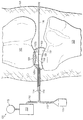
도 1a는 유체 시스템, 무릎 관절의 대퇴골과 경골 사이에 위치되는 주머니, 및 주머니 내의 매니폴드 구조물의 제 1 실시예를 포함하는, 무릎 관절에서 연골을 복구하기 위한 감압 치료 시스템의 개략적인 단면도이며;
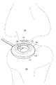
도 1b는 도 1a에 도시된 주머니 및 대퇴골의 개략적인 사시도이며;
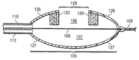
도 2a 및 도 2b는 주머니에 인가되는 감압을 갖고, 갖지 않는 도 1a에 도시된 주머니의 개략적인 단면도이며;
도 2c는 감압을 갖지 않는 도 1a에 도시되고, 도 7b에 도시된 바와 같이 회전되도록 평평해진 주머니의 개략적인 사시도이며;
도 3은 매니폴드 구조물의 제 2 실시예를 포함하는 도 1a에 도시된 주머니의 개략적인 단면도이며;
도 4는 스캐폴드 물질을 포함하는 도 1a에 도시된 주머니의 개략적인 단면도이며;
도 5는 차단벽 물질을 포함하는 도 1a에 도시된 주머니의 개략적인 단면도이며;
도 6은 도 1a에 도시된 유체 시스템에 대한 유체 컨트롤 시스템의 개략도이며;
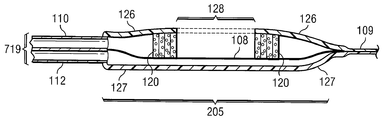
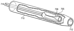
도 7a는 도 1a에 도시된 주머니의 개략적인 사시도이며, 도 7b는 회전되거나 접힌 후의 주머니의 사시도이고, 도 7c는 전달 카테터 내에 삽입된 회전된 주머니의 사시도이며;
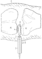
도 8은 무릎 관절로 삽입되는 도 7c의 전달 카테터 및 회전된 주머니의 개략적인 단면도이며;
도 9는 도 1a에 도시된 주머니와 유사한 다른 실시형태의 개략적인 측단면도이고;
도 10a 및 도 10b는 연장된 탭을 포함하는 도 1a에 도시된 주머니의 사시도 및 평면도를 각각 포함한다.1A is a schematic cross-sectional view of a decompression treatment system for repairing cartilage in a knee joint, including a first embodiment of a fluid system, a pocket positioned between the femur and tibia of the knee joint, and a manifold structure within the pocket;
1B is a schematic perspective view of the pocket and femur shown in FIG. 1A;
2A and 2B are schematic cross-sectional views of the bag shown in FIG. 1A with and without a reduced pressure applied to the bag;
FIG. 2C is a schematic perspective view of the bag shown in FIG. 1A without pressure reduction and flattened to rotate as shown in FIG. 7B;
3 is a schematic cross-sectional view of the bag shown in FIG. 1A including a second embodiment of a manifold structure;
4 is a schematic cross-sectional view of the bag shown in FIG. 1A including the scaffold material;
FIG. 5 is a schematic cross-sectional view of the bag shown in FIG. 1A including a barrier material; FIG.
FIG. 6 is a schematic diagram of a fluid control system for the fluid system shown in FIG. 1A; FIG.
FIG. 7A is a schematic perspective view of the bag shown in FIG. 1A, FIG. 7B is a perspective view of the bag after being rotated or folded, and FIG. 7C is a perspective view of a rotated bag inserted into the delivery catheter;
8 is a schematic cross-sectional view of the delivery catheter and rotated pocket of FIG. 7C inserted into the knee joint;
9 is a schematic side cross-sectional view of another embodiment similar to the bag shown in FIG. 1A;
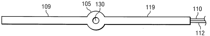
10A and 10B include a perspective view and a plan view, respectively, of the pocket shown in FIG. 1A including an elongated tab.
이어지는 예시적인 실시예에 대한 상세한 설명에서, 예시적인 실시예의 일부를 형성하는 첨부된 도면이 참조된다. 이러한 실시예들은 통상의 기술자가 본 발명을 실시할 수 있도록 충분히 상세하게 설명되며, 다른 실시예들이 이용될 수 있고 논리구조적, 기계적, 전기적 및 화학적인 변경이 본 발명의 사상 및 범위를 벗어나지 않은 채 수행될 수 있음이 이해된다. 통상의 기술자가 여기에서 설명된 실시예를 실시하는데 필요하지 않은 상세한 설명을 피하기 위해, 발명의 상세한 설명은 통상의 기술자에게 알려진 특정 정보를 생략할 수 있다. 그러므로, 이어지는 발명의 상세한 설명은 제한된 의미를 가지지 않고, 예시적인 실시예의 범위는 오직 첨부된 청구항에 의해서만 규정된다.In the detailed description of the exemplary embodiments that follow, reference is made to the accompanying drawings that form a part of the exemplary embodiments. These embodiments are described in sufficient detail to enable those skilled in the art to practice the invention, other embodiments may be utilized, and logic, mechanical, electrical, and chemical changes may be made without departing from the spirit and scope of the invention. It is understood that this may be done. In order to avoid the detailed description that a person skilled in the art does not need to practice the embodiments described herein, the detailed description of the invention may omit specific information known to the skilled person. The following detailed description, therefore, is not to be taken in a limiting sense, and the scope of the exemplary embodiments is defined only by the appended claims.
도 1a 및 도 1b를 참조하면, 감압을 적용하고, 예컨대, 대퇴골(102)과 경골(103)을 포함하는 환자의 다리(101) 내의 무릎 관절과 같은 환자의 신체 조직 부위에서 조직의 성장을 용이하는 감압 치료 시스템(100)이 도시된다. 무릎 관절의 임의의 부분은 회복이 요구되는 결손부, 예컨대 대퇴골(102)의 측면 관절구의 관절 연골 내의 결손부(104)가 발생될 수 있다. 또한, 결손부(104)는 전술한 바와 같은 미세골절 수술 부위일 수 있고, 여기서 유륜(areola) 결합조직, 조밀 결합조직 및 연골을 제한 없이 포함하는 신체의 구조물 및 지지대로서 기능하는 새로운 연골 조직 또는 임의의 조직의 성장을 재생, 회복, 추가 또는 촉진시키는 것이 요구되는 곳이다.Referring to FIGS. 1A and 1B, decompression is applied and facilitates the growth of tissue at a site of a body tissue of a patient, such as a knee joint in a
또한, 감압 치료 시스템(100)은 주머니(105) 내의 내벽(108)에 의해 분할되는 감압 챔버(106) 및 보강 챔버(107)를 포함하는 주머니(105)에 감압을 제공하기 위한 감압원(115)을 포함한다. 상기 챔버(106,107)는 공통 내벽(108) 없이 분리되는 챔버일 수 있다고 이해될 수 있다. 상기 주머니(105)는 감압 챔버(106)가 대퇴골(102)에 인접하여 골(102, 103) 사이에 배치된다. 또한, 결손부(104)는 감압 챔버(106)가 경골(103)의 그러한 결손부에 인접하여 배치됨에 따라 경골(103) 내에 있을 수 있음이 이해되어야 한다. 감압원(115)은 제 1 도관(110)을 거쳐 주머니(105)의 감압 챔버(106)에 유체가 통하도록 연결된다. 감압 치료 시스템(100)은 상기 결손부(104)를 거쳐 대퇴골(102)로부터 채출되는 혈액 또는 삼출물과 같은 체액을 수집하도록 상기 감압원(115) 및 상기 주머니(105)의 감압 챔버(106) 사이에서 유체가 통하도록 연결되는 캐니스터(113)를 더 포함한다. 일 실시예에서, 상기 감압원(115) 및 상기 캐니스터(113)는 단일 하우징 구조로 통합된다.The
이 명세서의 문맥에서, "감압"이라는 용어는 통상 치료되는 조직 부위에서의 주위 압력보다 낮은 압력을 의미한다. 대부분의 경우에, 이 감압은 환자가 위치하는 장소의 대기압보다 낮다. 용어 "진공" 및 "음압"이 조직 부위에 인가된 압력을 설명하기 위해 사용될 수 있을지라도, 조직 부위에 인가된 실제 압력은 완전한 진공과 일반적으로 관련된 압력보다 상당히 클 수 있다. 명명과 일치하여, 감압 또는 진공압의 증가는 절대압의 상대 감소를 언급하는 반면 감압 또는 진공압의 감소는 절대압의 상대 증가를 언급한다.In the context of this specification, the term “decompression” usually means a pressure lower than the ambient pressure at the tissue site being treated. In most cases, this decompression is lower than the atmospheric pressure at the location of the patient. Although the terms "vacuum" and "negative pressure" may be used to describe the pressure applied to a tissue site, the actual pressure applied to the tissue site may be significantly greater than the pressure generally associated with a complete vacuum. In line with the nomenclature, an increase in decompression or vacuum refers to a relative decrease in absolute pressure while a decrease in decompression or vacuum refers to a relative increase in absolute pressure.
상기 시스템(100)은 제 2 도관(112)을 통해 주머니(105)의 보강 챔버(107)에 유체가 통하도록 연결되는 제 1 유체 공급부(111)를 더 포함한다. 제 1 유체 공급부(111)는 보강 챔버(107)가 팽창하도록 정압 하에서 보강 챔버(107)를 채우기 위해 제 2 도관(112)을 통해서 보강 챔버(107)에 보강 물질을 제공하고, 주머니(105)의 내벽(108)뿐만 아니라 경골(103) 및 주변 조직에 정힘(positive force)을 가한다. 보강 챔버(107) 내의 보강 물질에 인가된 정압은 붕괴 없이 상기 대퇴골(102) 및 상기 경골(103) 사이에 쿠션을 동시에 제공하면서 보강 챔버(107)가 경골(103) 및 주변 조직의 형상과 윤곽을 일치시키기에 충분하다. 주머니(105)의 보강 챔버(107)는 경골(103) 및 주변 조직과 요구되는 완충성 및 일치를 이루기 위해 다수의 챔버를 포함할 수 있다는 것이 이해될 수 있다. 상기 보강 물질은 가스 또는 액체, 예컨대 퍼티(putty), 슬러리, 또는 콜로이드와 같은 고점도 압축 물질일 수 있다.The
제 1 도관(110) 및 제 2 도관(112) 모두는 커넥터(114,116)를 거쳐서 주머니(105)에 각각 결합 될 수 있다. 양 도관(110,112)은 도관 내의 체액 또는 혈액의 증진을 방지하기 위해 항응고제로 코팅될 수 있다. 본 명세서에 사용된 상기 용어 "결합된"은 분리된 물체를 통해 직접 결합 또는 간접 결합을 포함한다. 또한, 상기 용어 "결합된"은 동일한 물질의 조각으로 형성된 구성요소 각각에 의해 서로 연속되는 두 개 이상의 구성요소를 포함한다. 또한, 상기 용어 "결합된"은 화학적, 기계적, 열적, 또는 전기적 결합을 포함한다. 유체가 통하도록 결합은 유체가 지정된 부분 또는 위치 사이에서 유체가 통하도록 연결되는 것을 의미한다.Both the
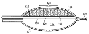
주머니(105)는 도 2a 및 도 2b의 감압 챔버(106)에 인가된 감압을 갖는 것과, 갖지 않는 것으로 각각 도시된다. 도 2a를 더 구체적으로 참조하면, 상기 주머니(105)는 상기 감압 챔버(106)의 외면을 형성하는 감압 외벽(126) 및 보강 챔버(107)의 외벽을 형성하는 보강 외벽(127)을 포함하는 두 개의 외벽을 포함한다. 상기 감압 외벽(126)은 일반적으로 상기 결손부(104)의 주변의 크기와 맞도록 성형되는 원형 개구부(128)를 갖는다. 상기 주머니(105)는 도 1a에 도시된 바와 같이, 대퇴골(102) 내의 결손부(104)의 양측에 위치된 두 개의 분리된 매니폴드 구성요소(120a,120b)일 수 있거나 도 1b에 도시된 바와 같이 감압 외벽(126)의 개구부(128)와 동심 정렬되는 내경을 갖는 형상에 있어서 실질적으로 원통형일 수 있는 매니폴드 구조물(120)을 더 포함한다. 상기 매니폴드 구조물(120)의 상부면은 감압 외벽(126)의 내측면에 대해 밀봉될 수 있다. 상기 매니폴드 구조물(120)은 챔버(106)가 압력 하에 있지 않는 경우에, 상기 내벽(108) 위에서 약간 떠 있도록 감압 외벽(126)과 내벽(108) 사이의 거리보다 다소 작은 높이를 가질 수 있다.The
감압이 도 2b에 도시된 바와 같이 상기 감압 챔버(106)에 인가되는 경우에, 상기 감압 외벽(126)은 상기 매니폴드 구조물(120)이 상기 내벽(108)에 밀어 넣어지고 상기 내벽(108)의 일부와의 밀봉을 형성해서 결손부(104) 상에 감압을 집중하면서 126'으로 나타낸 위치로 붕괴된다. 상기 매니폴드 구조물(120)의 내경에 의해 정의되는 내벽(108)의 일부는 매니폴드 구조물(120)을 통해 인가되는 감압의 결과로서 약간의 딤플부(108')를 형성한다. 상기 내벽(108)의 딤플부(108') 및 상기 매니폴드 구조물(120)의 내면(129)은 상기 결손부(104)에 인접하여 위치된 캐비티(130)를 정의한다. 따라서, 상기 감압 외벽(126)은 상기 감압 외벽(126)에서의 개구부(128)를 통해 상기 결손부(104)에 감압을 직접적으로 인가하기 위해 상기 결손부(104) 주위에 밀봉을 제공한다. 또한, 매니폴드 구조물(120)은 상기 외벽(126)이 상기 내벽(108)에 대해 붕괴되는 것을 방지하는 역할을 해서, 감압이 대퇴골(102)에서의 결손부(104)에 계속해서 인가되게 한다. 상기 매니폴드 구조물(120)은 단일 조각이든 다수의 매니폴드 구성요소(120a 및 120b)이든 캐비티(130)의 일부를 형성함에 따라 상기 감압 챔버(106) 내에서 여전히 기능을 하는 동안, 상기 대퇴골(102)과 내벽(108) 사이의 상기 감압 챔버(106) 내에서 적당한 구조적인 지지를 제공하기 위해 선택된다.When decompression is applied to the
내벽(108)은 액체 및 가스 모두를 포함하는 유체의 전달을 차단하기 위해 실질적으로 불침투성이다. 상기 내벽(108)은 주머니(105)의 제조 공정에 따라 단일 물질 층 또는 다수 층일 수 있다. 상기 매니폴드 구조물(120)은 감압 챔버(106)에 인가되는 감압 및 보강 챔버(107)에 인가되는 정압의 결과로서 약간의 딤플부(108')를 형성할 수 있을지라도, 상기 내벽(108)은 양측에 인가되는 압력에 응답하여 굽힘량 또는 수축량을 감소시키기 위해 실질적으로 구부러지지 않는다. 그러한 물질는, 예컨대 유리섬유(fiberglass), 금속, 고무, 또는 플라스틱을 홀로 또는 조합하여 포함할 수 있다. 감압 및 보강압(bracing pressure)이 상기 주머니(105)에 인가되는 경우에, 상기 내벽(108)은 캐비티(130)가 결손부(104)에 대해 붕괴되지 않는 것을 보장하기 위해 충분히 구부러지지 않거나 강성일 수 있다.The
또한, 외벽(126,127)은 유체의 전달을 실질적으로 차단하기 위해 불침투성 물질로 제작된다. 게다가, 상기 외벽(126,127)은 각각 감압 챔버(106)로의 감압 및 보강 챔버(107)로의 정압의 인가에 의해 생성되는 인장 응력 및 압축 응력을 견디도록 충분히 두꺼워야 한다. 따라서, 상기 외벽(126,127)은 동일 또는 상이한 성질을 갖는 다수의 물질 층으로 형성될 수 있다. 예컨대, 상기 외벽(126,127)은 압력 하에 있을 때 유체에 불침투성인 제 1 층 및 충분한 연성 및 구조적인 지지를 갖는 제 2 층을 가질 수 있다. 물론, 이 특성은 주머니(105)의 상기 외벽(126,127)을 제작하는데 사용되는 특수 물질에 의존한다.The
상기 외벽(126, 127)을 형성하는데 사용되는 물질는 고무와 같은 성질을 갖도록 1개 이상의 탄성중합체를 포함할 수 있다. 예컨대, 일부 실시예에서, 연성 물질는 100%보다 큰 신장율을 갖고 상당한 탄성을 갖는다. 물질의 탄성은 탄성 변형으로부터 회복되는 물질의 능력을 언급한다. 탄성중합체의 예는 천연 고무, 폴리이소프렌, 스티렌 부타디엔 고무, 클로로프렌 고무, 폴리부타디엔, 니트릴 고무, 부틸 고무, 에틸렌 프로필렌 고무, 에틸렌 프로필렌 디엔 모노머, 클로로술포네이티드 폴리에틸렌, 폴리설파이드 고무, 폴리우레탄, 및 실리콘을 포함하지만, 이들에 제한되지 않는다. 또한, 탄성중합체는 방향족 및 지방족 이소시아네이트에 기초된 탄성중합체를 포함하는 폴리우레탄 탄성중합체; 연성 폴리에틸렌 및 폴리프로필렌 호모폴리머 및 공폴리머를 포함하는 연성 폴리올레핀; 스티렌성 열가소성 탄성중합체; 폴리아미드 탄성중합체; 폴리아미드-에테르 탄성중합체; 에스테르-에테르 또는 에스테르-에스테르 탄성중합체; 연성 이오노머(ionomer); 열가소성 가황물; 연성 폴리(비닐 클로라이드) 호모폴리머 및 공폴리머; 연성 아크릴성 폴리머; 및 폴리(비닐 클로라이드)-폴리우레탄 합금과 같은 폴리(비닐 클로라이드) 합금 등의 블렌드 또는 합금을 포함할 수 있지만 이들에 제한되지 않는다. 또한, 외벽(105)은 폴리에스테르-폴리우레탄, 폴리에테르-폴리우레탄, 및 폴리카보네이트-폴리우레탄을 포함할 수 있지만 이들에 제한되지 않는다. 상술한 다른 탄성중합체의 물질는 1층으로 상기 외벽(126,127)을 형성하기 위해 블렌드로서 결합 될 수 있거나, 그렇지 않으면 분리 층으로 형성될 수 있다. 상기 외벽(126,127)은 생체 불활성 물질, 즉 물질에 대해 강한 면역 반응을 도출하지 않고 독성이 없지만, 시간에 따라 신체 내에서 붕괴되지 않은 물질로 형성될 수 있다.The material used to form the
상기 매니폴드 구조물(120)은 도 2b에 도시된 바와 같이 붕괴된 위치(126')에서 내벽(108)과 감압 외벽(126) 사이의 스페이서로서 지지를 제공하면서 감압 챔버(106) 내에서 감압을 결손부(104)에 분배한다. 상기 감압 외벽(126)이 대퇴골(102)에 대해 밀어 넣어지는 경우, 감압을 결손부(104)에 계속해서 분배하는 상기 매니폴드 구조물(120)을 포함하는 캐비티(130)를 거쳐서 감압이 결손부(104)에 직접 인가된다. 상기 매니폴드 구조물(120)은 매니폴드 구조물(120) 내에서 복수의 유로를 형성하기 위해 서로 유체가 통하도록 연결되는 복수의 셀을 포함하는 개방 셀 발포체 물질을 포함한다. 상기 셀 및 유로는 균일한 형상 및 크기일 수 있거나, 상기 매니폴드 구조물(120) 내에서 유로를 통해 유체의 흐름을 더 정확히 향하게 하기 위한 패턴 또는 무작위식 변형을 포함한다.The
일 예시적인 실시예에서, 상기 매니폴드 구조물(120)은 소수성 또는 친수성 중 어느 하나일 수 있는 발포체 물질이다. 제한되지 않는 일 예시에서, 상기 매니폴드 구조물(120)은 San Antonio, Texas의 Kinetic Concepts, Inc.로부터 입수가능한 GranuFoam® dressing 등의 개방 셀 망상 폴리우레탄 발포체이다. 상기 매니폴드 구조물(120)이 친수성 물질로 제조되는 예에서, 상기 매니폴드 구조물(120)은 또한 감압을 상기 결손부(104)에 매니폴드로서 계속 제공하면서, 캐비티(130)로부터 유체를 밖으로 수송(wick)하도록 기능한다. 상기 매니폴드 구조물(120)의 수송하는 성질은 모세관 유동 또는 다른 수송 메커니즘에 의해 결손부(104)로부터 떨어져서 유체를 빼낸다. 친수성 발포체의 예는 San Antonio, Texas의 Kinetic Concepts, Inc.로부터 입수가능한 V.A.C. WhiteFoam® dressing 등의 폴리비닐알코올, 개방 셀 발포체이다. 다른 친수성 발포체는 폴리에테르로 제조된 것을 포함할 수 있다. 친수성 특성을 나타낼 수 있는 다른 발포체는 친수성을 제공하기 위해 처리되거나 코팅된 소수성 발포체를 포함한다.In one exemplary embodiment, the
다른 실시예에서, 상기 매니폴드 구조물(120)은 상기 결손부(104)가 회복되고 감압 챔버(106)가 완전히 붕괴된 후에 환자의 신체로부터 제거되지 않는 생체흡수성 물질로 구성될 수 있다. 적합한 생체흡수성 물질은 폴리락트산(PLA) 및 폴리글리콜산(PGA)의 중합체 블렌드(polymeric blend)를 제한없이 포함할 수 있다. 또한, 중합체 블렌드는 폴리카보네이트, 포리퓨마레이트, 및 카프라락톤을 제한없이 포함할 수 있다. 상기 매니폴드 구조물(120)은 새로운 세포-성장을 위한 스캐폴드로서 더 기능하거나, 스캐폴드 물질은 세포-성장을 촉진하기 위해 매니폴드 구조물(120)과 함께 사용될 수 있다. 스캐폴드는 세포 성장을 위한 주형(template)을 제공하는 3차원 다공성 구조물과 같은 세포의 성장 및 조직의 형성을 증진하거나 촉진하기 위해 사용되는 물질 또는 구조물이다. 스캐폴드 물질의 예시적인 예는 합성, 생합성, 및 칼슘 포스페이트, 콜라겐, PLA/PGA, 산호색의 하이드록시 아파타이트(coral hydroxy apatites), 탄산염, 자가 조직, 또는 가공된 동종 이식편이나 이종 이식 물질와 같은 생물학적 물질을 포함한다.In another embodiment, the
또한, 상기 매니폴드 구조물(120)은 외벽(126)이 내벽(108)에 대하여 빠르게 붕괴되는 것을 방지하기 위해 감압 챔버(106) 내에 충분한 지지를 제공하는 폐쇄-셀 물질을 포함할 수 있다. 또한, 폐쇄-셀 물질은 복수의 셀을 포함하지만, 대부분의 셀은 상기 감압 챔버(106) 내에 많은 고체 구조적인 지지를 제공하도록 서로 유로와 유체가 통하도록 연결되지 않는다. 폐쇄-셀 물질은 매니폴드 구조물(120)의 3차원 형상을 유지해서 상기 감압 챔버(106) 내에 구조적인 지지를 제공하고 개방 셀이 유로를 통해서 감압의 흐름을 붕괴시키고 절단하는 것을 방지하기 위해 충분히 조밀하다.In addition, the
따라서, 상기 매니폴드 구조물(120) 내의 셀의 크기는 상기 매니폴드 구조물(120) 내의 복수의 셀을 통해서 유체의 통과를 용이하게 하기 위해 충분히 커야 하지만, 상기 감압 챔버(106) 내에서 구조적인 지지를 제공하는 낮은 공극으로 인해 충분히 작아야 한다. 상기 매니폴드 구조물(120) 내의 셀 크기는 정확히 알려져 있지 않을지라도, 공기 및 유체가 압력 하에 있을 때 이동되게 하는 충분한 투자율을 유지하는 저단부에서의 약 100마이크론과, 대퇴골(102)에 대해 충분한 구조적인 지지를 유지하는 고단부 상의 약 1500마이크론 사이이다. 또한, 매니폴드 구조물(120) 내의 셀 크기 및 숫자는 매니폴드 구조물(120)의 공극에 영향을 미친다. 일 실시예에서, 공극율은 매니폴드 구조물(120)이 개방 셀 구조를 통해서 유체 흐름을 계속 용이하게 하는 것을 보장하기 위해 약 50% 이상이어야 한다. 공극율은 매니폴드 구조물이 충분한 구조적인 지지를 제공하는 것을 보장하기 위해 약 85%보다 크지 않아야 한다. 따라서, 상기 매니폴드 구조물(120)의 공극율은 약 50% 내지 약 85%이어야 한다.Thus, the size of the cells in the
도 1a, 도 1b, 및 도 2b를 다시 참조하면, 상기 내벽(108)은 내벽(108)의 딤플부(108')와 매니폴드 구조물(120)의 내경면(129)이 결손부(104)와 접촉하는 것을 방지하기 위해 충분히 강성이다. 물질은 결손부(104)에 인접한 캐비티(130) 내에 위치될 수 있으며, 이는 결손부(104)의 치유를 증진하거나, 추가 구조적인 지지를 제공하거나, 차단벽을 제공해서 감압 챔버(106)를 결손부(104) 또는 상술한 것 모두로부터 분리한다. 예컨대, 추가 매니폴드 물질은 상술한 매니폴드 구조물(120)과 유사한 방식으로 추가적인 구조적인 지지를 제공하기 위해 및/또는 결손부(104)의 치유를 증진하는 스캐폴드 물질로 기능하기 위해 캐비티(130) 내에 위치될 수 있다. 또한, 매니폴드 구조물은 결손부(104)의 치유를 증진하는 스캐폴드 물질로 기능할 수 있다. 그러한 매니폴드 구조물은 감압 전달 시스템(100)이 제거된 후에 생체흡수가능하고 적소에 남겨질 수 있다.Referring again to FIGS. 1A, 1B, and 2B, the
상기 매니폴드 구조물(120)의 형상은, 감압이 가해질 때 감압 챔버(106) 내에서 내벽(108)에 대한 붕괴로부터 외벽(126)을 방지하는 임의의 것일 수 있다. 따라서, 매니폴드 구조물(120)은, 도 2a에 예시된 바와 같이, 감압 챔버(106)의 외벽(126)의 일부만을 지지할 수 있다. 대안으로, 매니폴드 구조물(320)은, 도 3에 도시된 바와 같이, 대부분의 감압 챔버(106)를 충전해서 감압 챔버(106)의 외벽(126)의 전체 내부 부분을 지지할 수 있다. 감압이 감압 챔버(106)에 인가될 때, 감압 외벽(126)은, 도 2b에 도시된 바와 같이, 126'로 나타낸 위치로 붕괴되지 않는다. 그러나, 매니폴드 구조물(320)은 내벽(108)에 대해 밀어 넣어져 결손부(104)에 인접하여 위치된 캐비티(130)를 형성한다. 따라서, 감압 외벽(126)은, 도 2b에 나타낸 바와 같이, 감압 외벽(126)에서의 개구부(128)를 통해 감압을 직접 결손부(104)에 인가하기 위하여 결손부(104) 주위에 밀봉을 제공한다. 이 특정 실시예는 일부 실시예에서 바람직한 바와 같이, 더 많은 지지가 대퇴골(102)에 요구되면 주머니(105)의 감압 챔버(106)에 더 많은 구조적인 지지를 제공한다. The shape of the
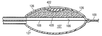
또한, 상기 매니폴드 구조물(320)은 결손부(104)의 치유를 증진하기 위해 스캐폴드 물질로서 기능하는 부분을 포함할 수 있다. 스캐폴드 부분은 대퇴골(102)에서의 간격 또는 빈 공간인 결손부를 채우도록 크기가 정해질 수 있고, 매니폴드 구조물(320)의 분리 또는 일체형 구성일 수 있다. 상기 매니폴드 구조물(320)은 생체흡수성일 수 있고, 감압 전달 시스템(10)이 제거된 후에 원위치에 남겨 질 수 있다. 도 4를 더 구체적으로 참조하면, 대퇴골(102)과 주머니(105)의 내벽(108) 사이에 추가적인 구조적인 지지를 동시에 제공하면서 결손부(104)의 재생을 증진시키기 위해 스캐폴드 성분(422)을 포함하는 매니폴드 구조물(420)이 도시된다. 상기 매니폴드 구조물(420)은 상술한 바와 같이 매니폴드 구조물(120)과 유사한 발포체 물질로 구성될 수 있다. 상기 스캐폴드 성분(422)은 상기 매니폴드 구조물(420)과 결손부(104) 사이에서 유체가 통과하기 용이하게 하기 위해 주로 개방 셀 물질을 포함한다. 이와 같이, 상기 스캐폴드 성분(422)은 대퇴골(102)과 주머니(105)의 내벽(108) 사이에 몇몇 쿠션을 동시에 제공하면서 결손부(104)의 전체면에 걸쳐 감압을 더 효율적으로 분배하기 위해 추가적인 매니폴드의 역할을 한다. 상기 매니폴드 구조물(420)의 스캐폴드 성분(422)은 세포의 성장 및/또는 연골 조직의 재생을 증진하기 위해 성장 인자, 셀 또는 영양소로 코팅되거나 주입(infuse)될 수 있다. 또한, 상기 스캐폴드 성분(422)은 자가 접종(self-seeded)됨으로써 감압은 세포를 주위 뼈 또는 다른 신체 조직으로부터 상기 스캐폴드 성분(422)의 셀로 끌어당기며, 그것은 새로운 조직을 성장 및/또는 형성할 수 있다. 또한, 상기 스캐폴드 성분(422)은 적용 전에 생체 외 세포로 접종될 수 있다.In addition, the
상기 스캐폴드 성분(422)에서의 세포의 사이즈는 구조물 내의 복수의 세포를 통과하여 유체 흐름을 유지하도록 충분히 커야 하지만, 유로가 거기에서 상당히 붕괴 되지 않고, 감압이 감압 챔버(106)에 인가될 때 상기 스캐폴드 성분(422)이 스캐폴드로서 기능하기 위해 그 형상을 유지하는 것을 보장하도록 상기 스캐폴드 성분(422) 내에서 충분한 구조적인 지지를 제공하는 낮은 공극으로 인해 충분히 작아야 한다. 감압 환경에서의 스캐폴드 성분(422)은 스캐폴드 성분(422) 내에서 유체가 통과하는 것을 중단시키거나 상당히 변경하는 것을 회피하기 위해 약 10%, 약 20%, 약 40%, 약 80%, 또는 그 사이의 임의 범위로 붕괴되는 개방 셀 구조를 가져야 한다. 스캐폴드 성분의 세포 크기 및 공극은 매니폴드 구조물(120)에 대해 상술한 바와 같이 동일한 범위에 있다.The size of the cells in the
스캐폴드 성분(422)은 주머니(105)가 대퇴골(102)로부터 제거될 때 스캐폴드 성분(422)이 매니폴드 구조물(120)로부터 용이하게 분리되게 하는 느슨한 인터페이스(loose interface)와 매니폴드 구조물(120)의 면을 접촉시키는 분리된 성분으로 구성될 수 있다. 따라서, 스캐폴드 성분(422)은 주머니(105)가 제거될 때 회복된 결손부(104)의 부위에 남아 있다. 대안으로, 스캐폴드 성분(422)은 예컨대 대퇴골(102)로부터 제거될 때 스캐폴드 성분(422)이 매니폴드 구조물(120)에 부착되게 하는 접착제를 사용하여 매니폴드 구조물(120)의 면에 접착되도록 구성될 수 있다. 따라서, 스캐폴드 성분(422)은 주머니(105)가 제거될 때 회복된 결손부(104)의 부위에 남아 있지 않는다. 스캐폴드 성분(422)이 매니폴드 구조물(420)에 의해 제거될 때 상술한 바와 같이 동일한 방식으로 기능하도록 이중(dual) 공극을 갖는 단일 성분(도시되지 않음)으로 제작될 수 있다. 이중 공극을 갖는 그러한 단일 성분은 미국특허 제6,695,823호 및 국제 출원 PCT/US2008/000596호(국제 공개 WO 2008/091521 A2)에 개시 및 기재되어 있으며, 그 모두는 여기에 참조문헌으로 포함되어 있다.The
상기 스캐폴드 성분(422)은 합성 물질, 생합성, 또는 인산칼슘, 콜라겐, PLA/PGA, 산호색의 하이드록시 아파타이트(coral hydroxy apatite), 탄산염 등의 바이올러지, 자가 조직, 또는 처리된 동종 이식편 또는 이종 이식 물질을 포함하는 물질로 구성될 수 있다. 상기 스캐폴드 성분(422)은 생체 불활성 물질, 즉 유독성이 아니거나 신체에서 초과 시간(body over time) 내에 분해되지 않는 물질에 대하여 강한 면역 반응을 유도하지 않는 물질로 형성될 수도 있다. 다른 실시예에서, 상기 스캐폴드 성분(422)은 생체 적합성 물질, 즉 유독성이 아니고 비유독성으로 분해되고, 배설이나 신진 대사에 의해 몸으로부터 제거되는 비면역성 화학종 물질에 대하여 강한 면역 반응을 유도하지 않는 물질로 형성된다. 또 다른 실시예에서, 스캐폴드 성분(422)은 생분해성 물질, 즉 간단한 화학종으로 생체 내에서 효소나 화학적으로 분해되는 물질로 형성된다.The
일부 실시예에서, 상기 스캐폴드 성분(422)은 생체 적합성 및/또는 생분해성 물질로 이루어진다. 따라서, 상기 스캐폴드 성분(422)은 주머니(105)가 무릎 관절로부터 제거되어도 결손부(104)의 부위에 남아있을 수 있다. 상기 스캐폴드 성분(422)이 무릎 관절에 남아있을 때, 부위에 대해 적절한 디멘션(dimensions)과 새 조직 성장을 지지해서 충분한 강도를 갖는 물질로 구성될 수 있다. 생체 적합성 및/또는 생분해성 물질은 락티드, 폴리(락티드)(PLA), 글리콜리드 폴리머, 폴리(글리콜산)(PGA), 폴리(락티드-공-글리콜리드)(PLGA), 에틸렌 글리콜/락티드 공폴리머, 폴리카프롤락톤, 폴리(파라디옥산온), 폴리히드록시부티르산염, 폴리우레탄, 폴리포스파젠, 폴리(에틸렌 글리콜)-폴리(락티드-공-글리콜리드) 공폴리머, 폴리히드록시산, 폴리카보네이트, 폴리아미드, 폴리무수물, 폴리아미노산, 폴리오르소에스터, 폴리아세탈, 분해성 폴리시아노아크릴레이트, 폴리카보네이트, 폴리푸마르산염, 분해성 폴리우레탄, 알부민, 콜라겐, 피브린, 합성 물질, 및 천연 폴리아미노 산 등의 단백질, 알지네이트, 헤파린, 다른 천연 발생되는 당(sugar) 단위의 생분해성 폴리머 등의 폴리당류, 진피, 심막, 힘줄, 또는 연골을 포함하는 처리된 시체나 비인간 조직을 포함할 수 있지만 이에 한정되지 않는다.In some embodiments, the
상기 스캐폴드 성분(422)이 생체 적합성 및/또는 생분해성 물질로 이루어지면 물질은 요구되는 기간 내에 분해되도록 설계될 수 있다. 일 실시예에서, 요구되는 저하 기간은 1주 내지 2주이다. 다른 실시예에서, 요구되는 저하 기간은 한 달 내지 1년이다. 또 다른 실시예에서, 요구되는 저하 기간은 1년보다 길다. 또한, 일부 실시예에서, 생체 적합성이나 생분해성 물질로 이루어지는 상기 스캐폴드 성분(422)을 만들기 위해 사용되는 물질의 분자량과 관련된 방식으로 분해될 수 있다. 따라서, 더 큰 분자량 물질은 더 긴 기간에 동안 그 구조적인 완전성을 유지하는 상기 스캐폴드 성분(422)이지만, 반면에 작은 분자량은 짧은 스캐폴드 수명을 갖도록 빠르게 저하될 수 있다.If the
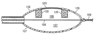
상술된 바와 같이, 공압 밀봉(pneumatic seal)(130)은 결손부(104)의 치유를 촉진하고, 추가적인 구조적인 지지를 제공하고, 결손부(104)로부터 감압 챔버(106)를 분리시키는 차단벽을 제공하는 결손부(104)에 인접한 빈 공간 내에 위치되는 물질을 포함할 수 있다. 도 5는 외벽(126) 내에 개구부를 덮고 공압 밀봉(130)을 폐쇄하는 차단벽 물질(520)을 포함하는 감압 챔버(106)의 다른 실시형태를 예시한다. 차단벽 물질(520)은 매니폴드 구조물(120)에 부착 및/또는 감압 챔버(106)의 외벽(126)에 부착될 수 있다. 따라서, 차단벽 물질(520)은 공압 밀봉(130)이 결손부(104)에 인접해서 배치될 때 결손부(104)의 표면에 직접적으로 접촉한다.As described above, a
상기 차단벽 물질(520)은 감압 챔버(106)의 외벽(126)에 일부 또는 전체를 덮는 한 조각 이상의 물질을 포함할 수 있다. 상기 차단벽 물질(520)은 결손부(104)를 공압 밀봉(130)과 직접 통과하는 것으로부터 분리하는 것과 동시에, 감압 챔버(106)가 결손부(104)와 유체가 통하도록 연결되게 하는 물질로 제조되는 것이 바람직하다. 이와 같이, 차단벽 물질(520)은, 예컨대 그물망(mesh), 체(sieve), 스크린(screen), 또는 간격이나 천공 패턴을 갖는 고체 시트일 수 있다. 차단벽 물질(520)은 충분한 강도를 가져 무릎 관절에 대해 추가적인 구조적인 지지를 제공할 수 있다.The
도 6을 참조하면, 감압 치료 시스템(100)은 각각 감압과 보강압을 측정하기 위해 제 1 및 제 2 도관(110,112)에 작동 가능하게 연결되는 압력 센서(140,142)를 더 포함할 수 있다. 상기 시스템은 보강 챔버(107)에 도관(112)을 통해 보강 유체를 제공하는 압력 센서(140,142), 감압원(115), 및 제 1 유체 공급부(111)에 전기적으로 접속된 제어 장치(145)를 더 포함한다. 압력 센서(140)는 감압 챔버(106)의 감압을 측정하고, 또한 제 1 도관(110)이 혈액이나 다른 체액으로 메워지는 지를 지시할 수 있다. 압력 센서(140)는 감압 챔버(106)에 제 1 도관(110)을 통해 감압원(115)에 의해 적용되는 감압 치료를 조절하는 제어 장치(145)에 피드백도 제공한다. 따라서, 압력 센서(142)는 보강 챔버(107)에 제 2 도관(112)을 통해 제 1 유체 공급부(111)에 적용되는 보강 유체의 정압을 측정한다. 압력 센서(142)는 보강 챔버(107)에 유체원(111)에 의해 적용되는 정압 치료를 조절하는 제어 장치(145)에 피드백도 제공한다. 또한, 제어 장치(145)는 각각 감압 챔버(106)와 보강 챔버(107)에 인가되는 감압 및 정압의 비교적인 양을 밸런스해서 충분한 압력이 상술된 바와 같이 각각 대퇴골(102)과 경골(103)의 양쪽 및 내벽(108)에 인가된다.Referring to FIG. 6, the
감압 치료 시스템(100)은 제 3 도관(152)을 통해 제 1 도관(110)에 유체가 통하도록 연결되고 제어 장치(145)에 작동되도록 연결되는 제 2 유체 공급부(150)를 포함할 수도 있다. 제 2 유체 공급부(150)는 항균제, 항바이러스제, 세포-성장 촉진제, 세정 유체, 또는 다른 화학 활성제를 제한없이 포함하는 성장제 및/또는 치유제를 결손부(104)에 전달하기 위해 사용될 수 있다. 시스템(100)은 상기 제 3 도관을 통하는 유체의 흐름을 제어하기 위해 제 3 도관(152)에 위치되는 제 1 밸브(154)와, 감압의 흐름을 제어하기 위하여 감압 공급부(115) 및 제 1 도관(110)과 제 3 도관(152) 사이의 접합부 사이에 위치되는 제 1 도관(110)을 포함한다. 환자에게 투여되는 특정 치료에서 요구되는 바와 같이, 제어 장치(145)는 제 2 유체 공급부(150)로부터 감압 챔버(106)에 감압 및/또는 유체의 전달을 제어하기 위하여 제 2 유체 공급부(150)와 제 1 및 제 2 밸브(154,156)에 전기적으로 연결된다. 제 2 유체 공급부(150)는 상술된 바와 같이 유체를 전달할 수 있지만, 감압 챔버(106)에 에어를 전달하여 결손(104)의 부위에 치유를 촉진하거나 배수를 할 수도 있다.The
도관(110, 112, 및 152)에 의해 제공되는 유체가 통과하기 위한 독립적인 경로는, 두 개 또는 다수의 루멘을 갖는 단일, 멀티 루멘 튜브를 제공하는 것을 포함하는 다수의 다른 방법으로 달성될 수 있다. 만일 멀티 루멘 튜브가 사용되면, 통상의 기술자는 압력 센서(140,142), 밸브(154,156), 도관과 결합된 다른 요소는 전달 튜브에서 특정 루멘과 유사하게 결합 될 수도 있다. 또한, 추가적인 루멘은 항균제, 항바이러스제, 세포-성장 촉진제트, 세정 유체, 또는 다른 화학 활성제를 제한없이 포함하는 에어나 다른 유체를 결손부(104) 부위에 독립적으로 도입하도록 제공될 수 있다.The independent path for the fluid provided by the
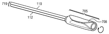
도 7a 및 도 2c를 참조하면, 주머니(105)의 외벽(126,127)은 상술된 바와 같이 연성을 갖는다. 따라서, 주머니(105)는 편평한 주머니(205)로서 도 2c에 보다 구체적으로 도시된 바와 같이 붕괴되거나 편평해질 수 있고, 도 7a에 점선에 의해 도시된 참조 부호 708에 의해 지시되는 모서리에 의해 내벽(108)이 외벽(126,127)과 교차하는 모서리에서 편평한 것이 바람직하다. 그 후, 편평한 주머니(205)는 도 7b에 도시된 바와 같이, 참조 부호 705에 의해 지시되는 바와 같이 대체로 관 형상으로 접히거나 회전(rolling)된다. 또한, 상술된 바와 같이 감압 챔버(106)와 보강 챔버(107)(도시 생략)가 내벽(108)과 같은 공동 벽을 공유하지 않지만, 분리벽을 가질 수 있을 것으로 이해될 것이다. 그 후, 제 1 및 제 2 도관(110, 112)을 따라 회전된 주머니(705)는 도 7c에 도시된 바와 같이, 전달 카테터(710)에 삽입될 것이다. 전달 카테터(710)는 점점 가늘어지는(taper) 원위부(712)를 가져 전달 카테터(710)가 대퇴골(102)과 경골(103) 사이의 무릎 관절에 외과적으로 또는 경피적으로 삽입되어, 도 8에 도시된 바와 같이, 회전된 주머니(705)를 요구되는 측면 부위에 인접한 결손부(104)에 전달할 수 있다. 경피적으로 삽입될 때 전달 카테터(710)는 환자의 피부 조직을 관통하는 무균 삽입 시스(sheath)(도시 생략)를 통해 삽입될 수 있다. 전달 카테터(710)의 원위부(712)는 상기 무릎 관절의 조직을 통해 전달 카테터(710)의 이동을 돕기 위해 점점 가늘어지지만, 회전된 주머니(705)가 전달 카테터(710)를 통해 밀어내고 환자의 무릎 관절에 삽입되게 하도록 점점 가늘어지는 원위부(712)에 충분히 큰 개구부를 가져야만 한다.7A and 2C, the
전달 카테터(710)는 충분한 강도를 제공하는 어떤 물질로 이루어져 전달 카테터(710)가 신체의 조직을 통과해 환자의 무릎 관절로 밀어넣어 지도록 할 것이다. 바람직하게, 전달 카테터(710)의 물질은 생체 불활성이므로 신체 조직을 둘러싼 상처, 유독성, 또는 면역 반응의 원인이 되지 않는다. 관심있는 물질은 폴리이미드, 폴리아미드, PBAX™, 폴리에틸렌, 플루오르폴리머, 폴리우레탄, 폴리이소프렌, 나일론, 철 등을 포함하지만 이에 한정되지 않는다. 다른 일 실시예에서, 전달 카테터(710)의 물질은 전달 카테터(710)에 연성량을 전달하게 할 것이다. 또한, 일 실시에에서, 전달 카테터(710)의 외부 직경은 물질로 코팅되어 튜브가 신체 조직에 부착되는 것을 방지한다. 예컨대, 배관(tubing)은 헤파린, 항응고제, 항프브로젠, 항지지제, 항트롬빈 생성 효소나 친수성 물질로 코팅될 것이다. 다른 실시형태에 있어서, 전달 카테터(710)의 외부 직경 및/또는 내부 직경은 실리콘, 친수성 코팅, Surmodics® 윤활제 등을 포함하지만 이에 제한되지 않는 윤활제로 코팅된다.The
다시 도 8을 참조하면, 전달 카테터(710)의 원위부(712)는 무릎 관절에 인접하여 위치될 때까지 환자 다리(101)의 피부(702)를 통과하여 밀어 넣어진다. 제 1 및 제 2 도관(110,112)은 도관(719)으로 총칭되고, 그 후 회전된 주머니(705)가 결손부(104)와 인접하여 요구되는 부위의 측면에 위치될 때까지, 회전된 주머니(705)가 전달 카테터(710)를 통과하고 상기 전달 카테터(710)의 원위부(712)를 나오도록 수동적으로 밀어넣어 질 것이다. 상술된 바와 같이, 결손부(104)을 갖는 대퇴골(102)은 미세골절 수술을 마쳤을 것이다. 미세골절 수술의 정확한 장비와 방법이 초과 되는 시간을 변경할 수 있는 것으로 이해되지만, 통상의 기술자는 미세골절 수술의 절차는 전문 의학의, 즉 무릎 관절의 외피(702)에 작은 절개를 하는 외과의나 전문 간호사를 일반적으로 포함하는 것으로 용이하게 이해된다. 길고 얇은 스코프(도시 생략), 예컨대 관절내시경은 피부(702)를 통과하고 신체 조직(703)을 통과해서 결손부(104) 부위에 삽입될 것이다. 필요하면 석화된 연골이 제거된다. 그 후, 외과의는 결손된 연골, 즉 결손부(104)에 가까운 대퇴골(102)에 미세골절, 즉 작은 구멍, 스크랩, 티어(tears)를 생성할 것이다. 길고 얇은 스코프가 제거된 후에 전달 카테터(710)는 동일한 피부 개구부(702)와 스코프에 의해 형성된 신체 조직(703) 패스를 통해 삽입될 것이다. 다른 실시예에서, 분리되고 추가적인 피부 개구부가 전달 카테터(710)를 수용하기 위해 형성될 수 있다. 전달 카테터(710)의 원위부(712)는 외과의 부위에 전달된 후에, 도관(719)이 기계적으로 또는 수동적으로 밀어 넣어져서 회전된 주머니(705)가 전달 카테터(710)의 원위부(712)를 통과하고 원위부(712) 위로 이동해서 결손부(104)에 인접한 요구되는 부위에 위치되게 할 것이다.Referring again to FIG. 8, the
회전된 주머니(705)는 결손부(104)에 인접한 요구되는 측면 위치에 도달한 후에 전달 카테터(710)가 환자의 다리(101)로부터 제거될 것이다. 그 후, 회전된 주머니(705)는 도 6b에 도시된 반대 방향으로 반대로 회전되어 결손부(104)에 인접해서 위치되는 캐비티(130)와 함께 비교적 편평해진 형상일 것이다. 제 1 및 제 2 도관(110,112)이 감압원(115)과 유체 공급부(111)에 재연결될 때, 정압은 보강 유체에 의해 보강 챔버(107)에 인가되어 팽장하고, 감압 챔버(106)에 감압을 동시에 인가하는 동안에 상술된 바와 같이 경골(103)과 내벽(108)에 힘을 가해서 도 1a에 도시되고, 상술된 바와 같이 감압 챔버(126)(도 2b 참조)에서 개구부(128)가 결손부(104)를 실질적으로 밀봉한다. 보강 챔버(107)에 인가되는 정압 및 매니폴드 구조물(120)과 내벽(108)을 통해 대퇴골(102)에 의해 가해지는 환자의 무게는, 보강 챔버(107)의 외벽(127)이 경골(103)의 굴곡 및 주변 신체 조직을 몰딩하게 한다. 또한, 보강 챔버(107)로의 정압의 인가는 감압이 캐비티(130)를 통해 결손부(104)에 인가된 이후에, 결손부(104)에 대해 감압 챔버(126)의 개구부(128)가 밀어 넣어지도록 대퇴골의 원위부에 대해 내벽(108)과 매니폴드 구조물(120)을 밀어 넣는다.The rotated
상술되고 도 1a, 도 4, 및 도 5에 도시된 바와 같이, 캐비티(130)는 스캐폴드 성분(422)으로 채워지거나, 캐비티(130)의 개구부를 폐쇄하는 차단벽 물질(520)에 의해 덮혀질 것이다. 구조에 관계없이, 감압은 감압 챔버(106)에서 개구부(128)를 통해 결손부(104)로 최종적으로 인가되어서, 그 결과 감압이 미세골절 수술에 의해 생성되는 구조를 통해 혈액과 뼈 골수의 침투를 증가시킴으로써 결손 부위에 혈액과 다른 자극제를 뽑아낼 것이다. 결손부(104)에 적용된 감압 치료나 치료는 결손부(104)의 사이즈와 형상, 및 분야에서 공지된 다양한 다른 요소에 따른다. 따라서, 인가되는 감압은 특정 주파수에서 지속적이고 변하기 쉽거나, 환자에 대하여 요구되는 치료와 결손부(104)의 특성에 따라 일반적으로 주기적인 초과 시간일 수 있다. 감압 챔버(106)에서 개구부(128)는 감압이 결손(104)에 직접적으로 인가될 뿐만 아니라 감압이 결손(104)에 인가되는 동안 무릎 관절로부터 시노비알(sinovial) 유체의 제거를 완화한다.As described above and shown in FIGS. 1A, 4, and 5, the
도 9를 참조하면, 주머니(905)의 다른 실시형태는 유사한 참조 부호로 지시되는 같은 요소를 포함하는 상술되는 주머니(105)에 실질적으로 유사하게 도시된다. 주머니(905)는 내벽(908)에 의해 분리되는 감압 챔버(906) 및 보강 챔버(907)를 포함하며, 각각의 챔버는 주머니(105)에 관하여 모두 상술된 바와 같이 각각 외벽(926 및 927)을 갖는다. 또한, 감압 챔버(906)는 매니폴드 구조물(920)도 포함하되, 상기 매니폴드 구조물(920)은 감압 챔버(906)의 대부분을 채우는 상술된 매니폴드 구조물(420)과 같은 방식으로 기능한다. 감압 챔버(906) 및 보강 챔버(907) 각각은 연장된 도관(914 및 916)을 포함하되, 상기 연장된 도관은 각각의 챔버와 유체가 통하도록 결합되고, 주머니(905)로부터 환자의 다리(101)의 피부를 통해 연장된다. 연장된 도관(914, 916)은 각각 그 사이에서 연장되는 내벽(908)을 갖는 감압 외벽(126)과 보강 외벽(127)의 통합된 부분일 수 있다. 매니폴드 구조물(920)은 감압 챔버(906)를 통해서 연장되고, 감압 챔버(906)의 연장된 도관(914)을 채운다. 연장된 도관(914, 916)의 원위부는 감압 챔버(906)에 감압을 제공하고 보강 챔버(907)에 정압 하에서 유체를 보강하기 위해, 상술된 바와 같이 같은 방법으로 기능하는 제 1 도관(114) 및 제 2 도관(116)에 유체가 통하도록 결합될 수 있다. 감압 챔버(906)의 연장된 도관(914)을 통해 연장되는 매니폴드 구조물(920)의 일부는 감압 챔버(906)를 위한 추가적인 구조적인 지지대를 제공하여, 주머니(905)가 전술한 바와 같이 더 쉽게 편평해지거나 회전되어 전달 카테터(710)(미도시)로 주머니(905)의 삽입을 용이하게 할 수 있다.With reference to FIG. 9, another embodiment of a
도 10a를 참조하면, 주머니(105)와 제 1 및 제 2 도관(110, 112)의 사시도가 도시된다. 주머니(105)는 제 1 및 제 2 도관(110, 112)(또한 도 1a 참조)에 유체가 통하도록 결합되는 측면 반대부의 주머니(105)의 단부로부터 연장되는 연장된 탭(109)을 더 포함한다. 연장된 탭(109)은 전술한 바와 같이 결손부(104)에 인접한 요구되는 측면 위치에 주머니(105)를 안내하고 조작하기에 유용하다. 보다 구체적으로, 관절경은 도 1a에 도시된 바와 같이, 무릎 관절을 통해 완벽하게 삽입되어, 전달 카테터(710)를 통해 주머니(105)의 미리 삽입될 수 있는 연장된 탭(109)에 대한 경로를 형성하고, 궁극적으로 환자 다리(101)의 다른 측의 외부로 연장될 수 있다. 연장된 탭(109)은 감압 챔버(106)의 외벽(126)에 고정되어, 결손부(104)에 인접한 감압 챔버(106)에서 개구부(128)의 위치 설정을 용이하게 할 수 있다. 연장된 탭(109)은 주머니(105)의 위치 설정을 용이하게 하기 위한 수술 중 무릎 관절에 삽입되기 전 또는 임의의 이후의 시점에 주머니(105)에 고정될 수 있다. 예컨대, 연장된 탭은 절개 경로를 통해 무릎 관절의 반대 측으로부터 주머니(105)에 고정되거나 나사 고정될 수 있는 전달 카테터(710)의 원위부(712)로 삽입될 수 있다. 그 후, 연장된 탭(109)은 요구되는 위치에 주머니(105)를 밀어넣기 위해 제 1 및 제 2 도관(110, 112)을 사용하는 대신에, 전달 카테터(710)를 통해 주머니(105)를 당기기 위해 사용될 수 있다.Referring to FIG. 10A, a perspective view of
또한, 주머니(105)는 시스(119)를 포함할 수 있되, 상기 시스(119)는 제 1 및 제 2 도관(110, 112)을 덮고, 주머니(105)에 직접적으로 고정된다. 시스(119)는 전술한 바와 같이 결손부(104)에 인접하여 요구되는 위치에 주머니(105)를 밀어넣기 위해 제 1 및 제 2 도관(110, 112)에 추가적인 힘을 제공하는 물질로 구성될 수 있다. 또한, 시스(119) 및 연장된 탭(109)은 도 10b에 도시된 바와 같이 하나의 연속적인 조각의 물질이어서, 주머니(105)를 결손부(104)에 인접한 요구되는 측면 위치에 밀어넣고/밀어넣거나 당기는 것과 감압 챔버(106)에서 개구부(128)의 위치를 설정하는 것을 더 용이하게 하여, 결손부(104)와 완전히 접촉할 수 있다.The
주머니 챔버, 전달 튜브 등의 설계 및 물질은 적용의 다른 실시예에서도 임의로 고려될 수 있고, 예컨대 조직 부위의 위치 및 사이즈, 결손부(104)에서 감압 챔버(106)의 개구부(128)의 위치를 유지시키기 위한 보강 챔버의 압력을 제한 없이 포함하는 다양한 요소에 의존한다. 하나 이상의 조직 부위를 포함하는 골 형상에 따라 주머니 챔버의 수, 사이즈, 및 타입이 변경될 수 있음이 여기에 기재된 모든 실시예에 대해서도 고려된다. 이와 같이, 보강 챔버를 더 잘 확장시키고 조직 부위를 포함하는 골에 하나 이상의 지지 폼(foam) 구조물을 밀봉하기 위해, 주머니 챔버는 두 개 또는 이상의 보강 챔버를 가질 수 있다.Designs and materials of pocket chambers, delivery tubes, and the like may optionally be considered in other embodiments of the application, for example, the location and size of the tissue site, the location of the
또한, 적용은 전술한 바와 같이 조직 부위에 감압 치료를 하는 방법으로 지시되지만, 보다 일반적으로 다음의 단계에 따른다. 이 방법은 조직 부위에서 골에 미세골절 수술을 실행하는 단계 및 그 후 조직 부위에 전술한 감압 전달 시스템의 실시예를 전달하는 단계를 포함한다. 그 후, 이 방법은 조직 부위 접촉면이 조직 부위와 접촉하도록 보강 물질을 보강 챔버에 전달하는 단계 및 감압이 조직 부위 가해지도록 유발하는 감압 챔버에 감압을 전달하는 단계를 포함한다. 이 방법은 미세골절 수술이 적용되는 임의의 조직 부위에 사용될 수 있다. 일부 실시예에서, 조직 부위는 전술한 바와 같이 무릎 관절에 위치할 수 있다.In addition, the application is directed to a method of decompressing a tissue site as described above, but more generally according to the following steps. The method includes performing microfracture surgery on the bone at the tissue site and then delivering the embodiment of the above-described decompression delivery system to the tissue site. The method then includes delivering the reinforcing material to the reinforcement chamber such that the tissue site contact surface is in contact with the tissue site and delivering the reduced pressure to the decompression chamber causing the decompression to be applied to the tissue site. This method can be used on any tissue site where microfracture surgery is applied. In some embodiments, the tissue site may be located in the knee joint as described above.
추가적인 실시예에서, 적용은 무릎에 미세골절 수술을 실시하는 방법을 지시한다. 방법은 무릎에 관절 연골 결손부의 베이스에서 골에 적어도 하나의 미세골절의 형성하는 단계 및 결손의 부위에 감압을 가하는 단계를 포함한다. 이러한 실시예에서 감압은 공지된 임의의 수단에 의해, 그리고 부위에 감압을 전달할 수 있는 임의의 공지된 시스템을 통해 가해질 수 있다. 일부 실시예에서, 감압은 전술한 감압 전달 시스템의 임의의 적절한 실시예를 사용하여 가해진다.In further embodiments, the application instructs how to perform microfracture surgery on the knee. The method includes forming at least one microfracture in the bone at the base of the articular cartilage defect in the knee and applying pressure to the site of the defect. In such an embodiment, the reduced pressure may be applied by any known means and through any known system capable of delivering a reduced pressure to the site. In some embodiments, the decompression is applied using any suitable embodiment of the decompression delivery system described above.
본 발명의 범위로부터 벗어남 없이, 다양한 변경이 전술한 임의의 시스템, 장치 및 방법으로 이루어질 수 있고, 전술한 기재 사항에 포함되고 첨부된 도면에 도시된 모든 내용은 예시적인 것에 불과하며 제한된 의미를 가지지 않는 것으로 의도된다.Various modifications may be made to any of the systems, devices, and methods described above without departing from the scope of the present invention, and all of the details contained in the above description and shown in the accompanying drawings are exemplary only and have a limited meaning. It is not intended to be.
본 명세서에 인용된 모든 참조문헌은 여기에서 참조로 도입된다. 여기에 참조문헌에 대한 논의는 단지 본 출원인에 의해 이루어진 주장을 요약하는 것에 불과하며, 어떤 참조문헌도 선행 기술을 구성하는 임의의 참조문헌에 해당하지 않는 것으로 의도된다. 본 출원인은 인용된 참조문헌의 정확성과 적합성에 이의를 제기하도록 권리를 유보한다.All references cited herein are hereby incorporated by reference. The discussion of references herein is merely a summary of the claims made by the applicant, and no references are intended to correspond to any references that make up the prior art. Applicant reserves the right to challenge the accuracy and suitability of cited references.
Claims (63)
감압을 제공하는 감압원;
정압을 제공하는 정압원;
상기 감압원과 유체가 통하도록 연결되고, 연성 물질로 형성된 벽을 가지며 상기 제 1 뼈 내의 결손부를 실질적으로 둘러싸도록 크기가 정해진 개구부를 갖는 감압 챔버, 그리고 상기 정압원과 유체가 통하도록 연결되고, 연성 물질로 형성된 벽을 갖는 보강 챔버(bracing chamber)로 형성되는 주머니(bladder)로서, 상기 감압 챔버 및 상기 보강 챔버 각각의 벽의 일부가 상기 주머니의 내벽을 형성하는 주머니; 및
상기 내벽과 상기 감압 챔버의 개구부 사이에 위치되고, 상기 결손부에 감압을 분배하고 상기 제 1 뼈와 상기 내벽 사이에 구조적인 지지를 제공하는 다공성 물질로 형성된 매니폴드를 포함하며;
상기 보강 챔버의 벽은 정압이 상기 보강 챔버에 인가되는 경우에 팽창되어, 상기 내벽 및 상기 두 개의 뼈 중 제 2 뼈 사이에 보강을 제공하고, 상기 감압 챔버의 벽은 감압이 상기 감압 챔버에 인가되는 경우에 수축되어, 상기 개구부가 상기 결손부 주위를 밀봉하도록 유발함으로써 상기 매니폴드가 상기 결손부에 감압을 분배하고 상기 내벽과 상기 제 1 뼈 사이에 지지를 제공하는 것을 특징으로 하는 결손부 치료 시스템.In a system for treating a defect in a first bone of two bones forming a joint:
A reduced pressure source providing reduced pressure;
A constant pressure source providing a constant pressure;
A pressure reducing chamber in fluid communication with the source of pressure reduction, a pressure reducing chamber having a wall formed of a soft material and having an opening sized to substantially surround the defect in the first bone, and in fluid communication with the positive pressure source, A bladder formed by a bracing chamber having a wall formed of a soft material, the bladder comprising: a bag in which a portion of each of the decompression chamber and each of the reinforcement chambers forms an inner wall of the bag; And
A manifold positioned between the inner wall and the opening of the decompression chamber, the manifold formed of a porous material that distributes decompression to the defect and provides structural support between the first bone and the inner wall;
The wall of the reinforcement chamber expands when a positive pressure is applied to the reinforcement chamber, providing reinforcement between the inner wall and a second one of the two bones, wherein the wall of the decompression chamber applies a decompression to the decompression chamber. Contraction, causing the opening to seal around the defect such that the manifold distributes the decompression to the defect and provides support between the inner wall and the first bone. system.
상기 매니폴드는 상기 내벽의 일부와 접촉하는 상기 감압 챔버를 부분적으로 채우고,
상기 매니폴드 및 상기 내벽의 일부는 상기 결손부에 인접하여 위치된 캐비티를 형성함으로써 상기 매니폴드가 상기 캐비티 및 상기 감압 챔버의 개구부를 통해 직접 상기 결손부에 감압을 제공하는 것을 특징으로 하는 결손부 치료 시스템.The method of claim 1,
The manifold partially fills the decompression chamber in contact with a portion of the inner wall,
The manifold and a portion of the inner wall form a cavity located adjacent to the defect so that the manifold provides pressure reduction to the defect directly through the cavity and the opening of the decompression chamber. Treatment system.
상기 매니폴드는 상기 결손부와 유체가 통하도록 연결되는 발포체 물질인 것을 특징으로 하는 결손부 치료 시스템.The method of claim 2,
And the manifold is a foam material in fluid communication with the defect.
상기 발포체 물질은 복수의 개방 셀을 포함하고 약 100 마이크론 내지 약 1,500 마이크론의 크기를 갖는 것을 특징으로 하는 결손부 치료 시스템.The method of claim 3, wherein
Wherein said foam material comprises a plurality of open cells and has a size of about 100 microns to about 1,500 microns.
상기 매니폴드는 새로운 조직 형성을 용이하게 하기 위하여 상기 결손부를 채우도록 크기가 정해진 스캐폴드 성분을 더 포함하는 것을 특징으로 하는 결손부 치료 시스템.The method of claim 2,
Wherein the manifold further comprises a scaffold component sized to fill the defect to facilitate new tissue formation.
상기 내벽은 상기 보강 챔버 및 상기 감압 챔버 사이의 공동(common) 벽인 것을 특징으로 하는 결손부 치료 시스템.The method of claim 2,
And the inner wall is a common wall between the reinforcement chamber and the decompression chamber.
상기 내벽은 실질적으로 강성인 것을 특징으로 하는 결손부 치료 시스템.The method according to claim 6,
Wherein said inner wall is substantially rigid.
상기 제 1 뼈 및 상기 보강 챔버 사이에 추가적인 보강을 제공하기 위해 상기 캐비티에 위치된 발포체 구조물을 더 포함하는 것을 특징으로 하는 결손부 치료 시스템.The method of claim 2,
And the foam structure located in the cavity to provide additional reinforcement between the first bone and the reinforcement chamber.
상기 발포체 구조물은 생체흡수성인 것을 특징으로 하는 결손부 치료 시스템.The method of claim 8,
And said foam structure is bioabsorbable.
상기 발포체 구조물은 조직 성장 및/또는 재생을 위한 스캐폴드의 역할을 하는 것을 특징으로 하는 결손부 치료 시스템.The method of claim 8,
Wherein said foam structure serves as a scaffold for tissue growth and / or regeneration.
상기 발포체 물질은 성장 인자 또는 영양소로 코팅되거나, 상기 성장 인자 또는 상기 영양소가 주입되는 것을 특징으로 하는 결손부 치료 시스템.The method of claim 10,
Wherein said foam material is coated with growth factors or nutrients, or said growth factors or said nutrients are infused.
상기 발포체 구조물은 상기 매니폴드에 부착되는 것을 특징으로 하는 결손부 치료 시스템.The method of claim 8,
And the foam structure is attached to the manifold.
상기 매니폴드는 상기 감압 챔버를 실질적으로 채우고 상기 감압 챔버의 개구부를 덮음으로써, 상기 매니폴드가 상기 개구부를 통해 상기 결손부에 직접 감압을 분배하는 것을 특징으로 하는 결손부 치료 시스템.The method of claim 1,
Wherein the manifold substantially fills the decompression chamber and covers the opening of the decompression chamber, whereby the manifold dispenses decompression directly to the defect through the opening.
상기 매니폴드는 상기 결손부와 유체가 통하도록 연결되는 발포체 물질인 것을 특징으로 하는 결손부 치료 시스템.The method of claim 13,
And the manifold is a foam material in fluid communication with the defect.
상기 발포체 물질은 복수의 개방 셀을 포함하고 약 100 마이크론 내지 약 1,500 마이크론의 크기를 갖는 것을 특징으로 하는 결손부 치료 시스템.The method of claim 14,
Wherein said foam material comprises a plurality of open cells and has a size of about 100 microns to about 1,500 microns.
상기 내벽은 상기 보강 챔버 및 상기 감압 사이의 공동 벽인 것을 특징으로 하는 결손부 치료 시스템.The method of claim 13,
And the inner wall is a cavity wall between the reinforcement chamber and the decompression chamber.
상기 내벽은 실질적으로 연성인 것을 특징으로 하는 결손부 치료 시스템.17. The method of claim 16,
Wherein said inner wall is substantially soft.
상기 매니폴드는 조직 형성을 용이하게 하기 위해 상기 결손부를 채우도록 크기가 정해진 스캐폴드 성분을 더 포함하는 것을 특징으로 하는 결손부 치료 시스템.The method of claim 13,
The manifold further comprises a scaffold component sized to fill the defect to facilitate tissue formation.
상기 스캐폴드 성분은 상기 제 1 뼈 및 상기 보강 챔버 사이에 추가적인 보강을 제공하는 것을 특징으로 하는 결손부 치료 시스템.The method of claim 18,
And the scaffold component provides additional reinforcement between the first bone and the reinforcement chamber.
상기 스캐폴드 성분은 생체흡수성인 것을 특징으로 하는 결손부 치료 시스템.The method of claim 18,
And wherein said scaffold component is bioabsorbable.
상기 스캐폴드 성분은 상기 결손부에 부착되는 것을 특징으로 하는 결손부 치료 시스템.The method of claim 20,
Wherein said scaffold component is attached to said defect.
상기 스캐폴드 성분은 상기 매니폴드에 부착되는 것을 특징으로 하는 결손부 치료 시스템.The method of claim 20,
And the scaffold component is attached to the manifold.
상기 스캐폴드 성분은 성장 인자 또는 영양소로 코팅되거나, 상기 성장 인자 또는 상기 영양소가 주입되는 것을 특징으로 하는 결손부 치료 시스템.The method of claim 18,
Wherein said scaffold component is coated with a growth factor or nutrient, or wherein said growth factor or said nutrient is infused.
상기 감압 챔버 및 상기 보강 챔버의 벽은 하나 이상의 탄성중합체로 구성되는 것을 특징으로 하는 결손부 치료 시스템.The method of claim 1,
And the wall of the decompression chamber and the reinforcement chamber is comprised of one or more elastomers.
상기 제 1 뼈 내의 결손부에 수술을 수행하는 단계;
상기 결손부에 인접한 관절에 감압 챔버를 위치시키는 단계;
상기 감압 챔버 및 상기 두 개의 뼈 중 제 2 뼈 사이의 관절에 보강 챔버를 위치시키는 단계;
상기 결손부 및 상기 보강 챔버에 인접한 감압 챔버 내에 매니폴드를 위치시키는 단계;
상기 매니폴드가 상기 제 1 뼈에 대해 밀어 넣어져 상기 감암 챔버를 상기 두 개의 뼈 중 제 2 뼈에 대하여 보강하도록 상기 보강 챔버에 정압을 인가하는 단계; 및
상기 감압 챔버 및 상기 매니폴드의 개구부를 통해 상기 결손부에 감압을 인가하는 단계를 포함하는 것을 특징으로 하는 결손부 치료 방법.A method of treating a defect in a first bone of two bones forming a joint:
Performing surgery on a defect in the first bone;
Positioning a decompression chamber in a joint adjacent the defect;
Positioning a reinforcement chamber in a joint between the decompression chamber and a second one of the two bones;
Positioning a manifold in a decompression chamber adjacent said defect and said reinforcement chamber;
Applying a positive pressure to the reinforcement chamber such that the manifold is pushed against the first bone to reinforce the sensitization chamber with respect to a second of the two bones; And
And applying pressure to the defect through the decompression chamber and the opening of the manifold.
상기 결손부는 골관절염을 포함하는 것을 특징으로 하는 결손부 치료 방법.The method of claim 25,
The method of claim 1, wherein the defect comprises osteoarthritis.
상기 관절은 무릎인 것을 특징으로 하는 결손부 치료 방법.The method of claim 25,
And the joint is a knee.
상기 관절은 팔꿈치인 것을 특징으로 하는 결손부 치료 방법.The method of claim 25,
And the joint is an elbow.
상기 결손부에 인접하여 발포체 물질을 적용하는 단계를 더 포함하는 것을 특징으로 하는 결손부 치료 방법.The method of claim 25,
Further comprising applying a foam material adjacent said defect.
상기 발포체 물질은 생체흡수성인 것을 특징으로 하는 결손부 치료 방법.The method of claim 29,
Wherein said foam material is bioabsorbable.
상기 발포체 물질은 상기 매니폴드로부터 분리가능한 것을 특징으로 하는 결손부 치료 방법.31. The method of claim 30,
Wherein said foam material is separable from said manifold.
상기 발포체 물질은 상기 매니폴드에 부착되는 것을 특징으로 하는 결손부 치료 방법.The method of claim 29,
Wherein said foam material is attached to said manifold.
상기 발포체 물질은 유로를 형성하는 복수의 개방 셀을 포함하는 것을 특징으로 하는 결손부 치료 방법.The method of claim 29,
And wherein said foam material comprises a plurality of open cells forming a flow path.
상기 발포체 물질은 조직 성장을 위한 스캐폴드의 역할을 하는 것을 특징으로 하는 결손부 치료 방법.The method of claim 33, wherein
Wherein said foam material serves as a scaffold for tissue growth.
상기 발포체 물질은 상기 결손부에 적용 전에 성장 인자, 셀 및/또는 영양소로 코팅되거나, 상기 성장 인자, 셀 및/또는 영앙소가 주입되는 것을 특징으로 하는 결손부 치료 방법.35. The method of claim 34,
Wherein said foam material is coated with growth factors, cells and / or nutrients, or said growth factors, cells and / or nutrients are infused prior to application to said defects.
상기 발포체 물질의 퍼센트 공극률은 약 50%이상인 것을 특징으로 하는 결손부 치료 방법.The method of claim 29,
And wherein the percent porosity of the foam material is at least about 50%.
상기 무릎 내의 관절 연골 결손부를 가지는 뼈에 적어도 하나의 미세골절을 생성하는 단계; 및
상기 관절 연골 결손부에 감압을 인가하는 단계를 포함하는 것을 특징으로 하는 무릎 수술 방법.In the method of performing surgery on the knee:
Generating at least one microfracture in a bone having articular cartilage defects in the knee; And
Knee surgery method comprising the step of applying a decompression to the joint cartilage defect.
상기 감압은 제 1 항 내지 제 24 항 중 어느 하나의 감압 전달 시스템을 사용하여 인가되는 것을 특징으로 하는 무릎 수술 방법.39. The method of claim 37,
The method of claim 1, wherein the decompression is applied using the decompression delivery system of claim 1.
감압원과 유체를 교환하는 감압 포트 및 상기 제 1 뼈 내의 결손부를 실질적으로 둘러싸도록 크기가 정해진 개구부를 갖는 감압 주머니;
정압원과 유체를 교환하는 정압 포트 및 상기 감압 주머니에 고정되는 보강 주머니; 및
상기 결손부에 감압을 분배하기 위해 상기 개구부에 인접하여 감압 주머니 내에 위치되고, 상기 제 1 뼈와 상기 보강 주머니 사이에 구조적인 지지를 제공하는 매니폴드를 포함하고;
상기 보강 주머니는 정압이 상기 정압 포트에 인가되는 경우 팽창되어, 상기 매니폴드와 상기 두 개의 뼈 중 제 2 뼈 사이에 지지를 제공하고, 상기 감압 주머니는 감압이 상기 보강 주머니의 상기 감압 포트에 인가되는 경우 상기 결손부 주위의 개구부를 밀봉하여, 상기 매니폴드를 통해 상기 결손부에 감압을 분배하고 상기 매니폴드와 상기 제 1 뼈 사이에 지지를 제공하는 것을 특징으로 하는 주머니.In a pocket for treating a defect in a first bone of two bones forming a joint:
A decompression bag having a decompression port for exchanging fluid with the decompression source and an opening sized to substantially surround the defect in the first bone;
A positive pressure port for exchanging fluid with a positive pressure source and a reinforcement bag fixed to the pressure reducing bag; And
A manifold positioned within the decompression bag adjacent the opening for dispensing decompression to the defect and providing structural support between the first bone and the reinforcement bag;
The reinforcement bag is inflated when positive pressure is applied to the positive pressure port, providing support between the manifold and a second of the two bones, wherein the decompression bag is applied to the decompression port of the reinforcement bag. Sealing the opening around the defect, thereby distributing a pressure reduction through the manifold to the defect and providing support between the manifold and the first bone.
상기 매니폴드는 상기 감압 주머니를 실질적으로 채우고 상기 감압 주머니의 개구부를 덮음으로써, 상기 매니폴드가 상기 개구부를 통해 상기 결손부에 직접적으로 감압을 분배하는 것을 특징으로 하는 주머니.The method of claim 40,
Wherein the manifold substantially fills the decompression bag and covers the opening of the decompression bag, whereby the manifold dispenses decompression directly to the defect through the opening.
상기 매니폴드는 상기 결손부와 유체가 통하도록 연결되는 발포체 물질인 것을 특징으로 하는 주머니.42. The method of claim 41 wherein
And said manifold is a foam material in fluid communication with said defect.
상기 발포체 물질은 복수의 개방 셀을 포함하고 약 100 마이크론 내지 약 1,500 마이크론의 크기를 갖는 것을 특징으로 하는 주머니.42. The method of claim 41 wherein
And the foam material comprises a plurality of open cells and has a size of about 100 microns to about 1,500 microns.
상기 보강 주머니와 상기 감압 사이에 공동 벽을 더 포함하는 것을 특징으로 하는 주머니.42. The method of claim 41 wherein
And a cavity wall between the reinforcement bag and the decompression bag.
상기 공동 벽은 실질적으로 연성인 것을 특징으로 하는 주머니.45. The method of claim 44,
And said cavity wall is substantially soft.
상기 매니폴드는 조직 형성을 용이하게 하기 위해 상기 결손부를 채우도록 크기가 정해진 스캐폴드 성분을 더 포함하는 것을 특징으로 하는 주머니.42. The method of claim 41 wherein
And the manifold further comprises a scaffold component sized to fill the defect to facilitate tissue formation.
상기 스캐폴드 성분은 상기 제 1 뼈 및 상기 보강 주머니 사이에 추가적인 지지를 제공하는 것을 특징으로 하는 주머니.The method of claim 46,
And the scaffold component provides additional support between the first bone and the reinforcement bag.
상기 스캐폴드 성분은 생체흡수성인 것을 특징으로 하는 주머니.The method of claim 46,
Wherein said scaffold component is bioabsorbable.
상기 스캐폴드 성분은 상기 결손부에 부착되는 것을 특징으로 하는 주머니.49. The method of claim 48 wherein
And the scaffold component is attached to the defect.
상기 스캐폴드 성분은 상기 매니폴드에 부착되는 것을 특징으로 하는 주머니.49. The method of claim 48 wherein
And the scaffold component is attached to the manifold.
상기 스캐폴드 성분은 성장 인자 또는 영양소로 코팅되거나, 상기 성장 인자 또는 상기 영양소가 주입되는 것을 특징으로 하는 주머니.The method of claim 46,
Wherein said scaffold component is coated with a growth factor or nutrient, or wherein said growth factor or said nutrient is infused.
상기 감압 주머니 및 상기 보강 주머니는 하나 이상의 탄성중합체로 구성되는 것을 특징으로 하는 주머니.The method of claim 40,
Wherein said pressure reducing bag and said reinforcing bag are comprised of one or more elastomers.
상기 매니폴드는 상기 감압 주머니의 일부와 접촉하는 상기 감압 주머니를 부분적으로 채우고, 상기 매니폴드 및 상기 감압 주머니의 나머지 일부는 상기 결손부에 인접하여 위치되는 캐비티를 형성함으로써, 상기 매니폴드가 상기 감압 주머니 내의 캐비티 및 개구부를 통해 간접적으로 상기 결손부에 감압을 제공하는 것을 특징으로 하는 주머니.The method of claim 40,
The manifold partially fills the decompression bag in contact with a portion of the decompression bag, and the manifold and the remaining part of the decompression bag form a cavity located adjacent to the defective portion, such that the manifold is decompressed. A bag, characterized in that to provide pressure reduction to the defect indirectly through a cavity and opening in the bag.
상기 매니폴드는 상기 결손부와 유체가 통하도록 연결되는 발포체 물질인 것을 특징으로 하는 주머니.The method of claim 53 wherein
And said manifold is a foam material in fluid communication with said defect.
상기 발포체 물질은 복수의 개방 셀을 포함하고 약 100 마이크론 내지 약 1,500 마이크론의 크기를 갖는 것을 특징으로 하는 주머니.The method of claim 54, wherein
And the foam material comprises a plurality of open cells and has a size of about 100 microns to about 1,500 microns.
상기 매니폴드는 새로운 조직 형성을 용이하게 하기 위해 상기 결손부를 채우도록 크기가 정해진 스캐폴드 성분을 더 포함하는 것을 특징으로 하는 주머니.The method of claim 53 wherein
The manifold further comprises a scaffold component sized to fill the defect to facilitate new tissue formation.
상기 보강 주머니 및 상기 감압 사이에 공동 벽을 더 포함하는 것을 특징으로 하는 주머니.The method of claim 53 wherein
And a cavity wall between the reinforcement bag and the decompression bag.
상기 공동 벽은 실질적으로 강성인 것을 특징으로 하는 주머니.The method of claim 57,
And said cavity wall is substantially rigid.
상기 제 1 뼈 및 상기 보강 주머니 사이에 추가적인 지지를 제공하기 위해 상기 캐비티에 위치된 발포체 구조물을 더 포함하는 것을 특징으로 하는 주머니.The method of claim 53 wherein
And a foam structure positioned in the cavity to provide additional support between the first bone and the reinforcement bag.
상기 발포체 구조물은 생체흡수성인 것을 특징으로 하는 주머니.The method of claim 59,
And said foam structure is bioabsorbable.
상기 발포체 구조물은 조직 성장을 위한 스캐폴드의 역할을 하는 것을 특징으로 하는 주머니.The method of claim 59,
Said foam structure serving as a scaffold for tissue growth.
상기 발포체 물질은 성장 인자 또는 영양소로 코팅되거나, 상기 성장 인자 또는 상기 영양소가 주입되는 것을 특징으로 하는 주머니.62. The method of claim 61,
The foam material is coated with a growth factor or nutrient, or the growth factor or nutrient is infused.
상기 발포체 구조는 상기 매니폴드에 부착되는 것을 특징으로 하는 주머니.The method of claim 59,
And the foam structure is attached to the manifold.
Applications Claiming Priority (2)
| Application Number | Priority Date | Filing Date | Title |
|---|---|---|---|
| US14159308P | 2008-12-30 | 2008-12-30 | |
| US61/141,593 | 2008-12-30 |
Publications (1)
| Publication Number | Publication Date |
|---|---|
| KR20110107357A true KR20110107357A (en) | 2011-09-30 |
Family
ID=42285847
Family Applications (1)
| Application Number | Title | Priority Date | Filing Date |
|---|---|---|---|
| KR1020117017759A KR20110107357A (en) | 2008-12-30 | 2009-12-21 | Reduced pressure augmentation of microfracture procedures for cartilage repair |
Country Status (13)
| Country | Link |
|---|---|
| US (3) | US8702711B2 (en) |
| EP (1) | EP2370009B1 (en) |
| JP (1) | JP5607071B2 (en) |
| KR (1) | KR20110107357A (en) |
| CN (1) | CN102271600B (en) |
| AU (1) | AU2009333066B2 (en) |
| BR (1) | BRPI0918196A2 (en) |
| CA (1) | CA2746515A1 (en) |
| MX (1) | MX2011007082A (en) |
| RU (1) | RU2011127676A (en) |
| SG (1) | SG172010A1 (en) |
| TW (1) | TW201029691A (en) |
| WO (1) | WO2010078118A2 (en) |
Cited By (1)
| Publication number | Priority date | Publication date | Assignee | Title |
|---|---|---|---|---|
| KR20230026083A (en) | 2021-08-17 | 2023-02-24 | 전남대학교산학협력단 | scaffold for cartilage regeneration |
Families Citing this family (4)
| Publication number | Priority date | Publication date | Assignee | Title |
|---|---|---|---|---|
| WO2013066426A2 (en) | 2011-06-24 | 2013-05-10 | Kci Licensing, Inc. | Reduced-pressure dressings employing tissue-fixation elements |
| EP3466457B1 (en) | 2012-12-06 | 2023-03-08 | IC Surgical, Inc. | Adaptable wound drainage system |
| JP6295182B2 (en) * | 2014-11-05 | 2018-03-14 | グンゼ株式会社 | Tissue regeneration substrate |
| US20230211049A1 (en) * | 2021-09-20 | 2023-07-06 | Industry Foundation Of Chonnam National University | Scaffolds for cartilage regeneration and method for treatment of cartilage defects using the same |
Family Cites Families (187)
| Publication number | Priority date | Publication date | Assignee | Title |
|---|---|---|---|---|
| US1355846A (en) * | 1920-02-06 | 1920-10-19 | David A Rannells | Medical appliance |
| US2547758A (en) | 1949-01-05 | 1951-04-03 | Wilmer B Keeling | Instrument for treating the male urethra |
| US2632443A (en) | 1949-04-18 | 1953-03-24 | Eleanor P Lesher | Surgical dressing |
| GB692578A (en) | 1949-09-13 | 1953-06-10 | Minnesota Mining & Mfg | Improvements in or relating to drape sheets for surgical use |
| US2682873A (en) | 1952-07-30 | 1954-07-06 | Johnson & Johnson | General purpose protective dressing |
| NL189176B (en) | 1956-07-13 | 1900-01-01 | Hisamitsu Pharmaceutical Co | PLASTER BASED ON A SYNTHETIC RUBBER. |
| US2969057A (en) | 1957-11-04 | 1961-01-24 | Brady Co W H | Nematodic swab |
| US3066672A (en) | 1960-09-27 | 1962-12-04 | Jr William H Crosby | Method and apparatus for serial sampling of intestinal juice |
| US3367332A (en) | 1965-08-27 | 1968-02-06 | Gen Electric | Product and process for establishing a sterile area of skin |
| US3520300A (en) | 1967-03-15 | 1970-07-14 | Amp Inc | Surgical sponge and suction device |
| US3568675A (en) | 1968-08-30 | 1971-03-09 | Clyde B Harvey | Fistula and penetrating wound dressing |
| US3682180A (en) | 1970-06-08 | 1972-08-08 | Coilform Co Inc | Drain clip for surgical drain |
| BE789293Q (en) | 1970-12-07 | 1973-01-15 | Parke Davis & Co | MEDICO-SURGICAL DRESSING FOR BURNS AND SIMILAR LESIONS |
| US3826254A (en) | 1973-02-26 | 1974-07-30 | Verco Ind | Needle or catheter retaining appliance |
| DE2527706A1 (en) | 1975-06-21 | 1976-12-30 | Hanfried Dr Med Weigand | DEVICE FOR THE INTRODUCTION OF CONTRAST AGENTS INTO AN ARTIFICIAL INTESTINAL OUTLET |
| DE2640413C3 (en) | 1976-09-08 | 1980-03-27 | Richard Wolf Gmbh, 7134 Knittlingen | Catheter monitor |
| NL7710909A (en) | 1976-10-08 | 1978-04-11 | Smith & Nephew | COMPOSITE STRAPS. |
| GB1562244A (en) | 1976-11-11 | 1980-03-05 | Lock P M | Wound dressing materials |
| US4080970A (en) | 1976-11-17 | 1978-03-28 | Miller Thomas J | Post-operative combination dressing and internal drain tube with external shield and tube connector |
| US4139004A (en) | 1977-02-17 | 1979-02-13 | Gonzalez Jr Harry | Bandage apparatus for treating burns |
| US4184510A (en) | 1977-03-15 | 1980-01-22 | Fibra-Sonics, Inc. | Valued device for controlling vacuum in surgery |
| US4165748A (en) | 1977-11-07 | 1979-08-28 | Johnson Melissa C | Catheter tube holder |
| US4245637A (en) | 1978-07-10 | 1981-01-20 | Nichols Robert L | Shutoff valve sleeve |
| SE414994B (en) | 1978-11-28 | 1980-09-01 | Landstingens Inkopscentral | VENKATETERFORBAND |
| GB2047543B (en) | 1978-12-06 | 1983-04-20 | Svedman Paul | Device for treating tissues for example skin |
| US4266545A (en) | 1979-04-06 | 1981-05-12 | Moss James P | Portable suction device for collecting fluids from a closed wound |
| US4284079A (en) | 1979-06-28 | 1981-08-18 | Adair Edwin Lloyd | Method for applying a male incontinence device |
| US4261363A (en) | 1979-11-09 | 1981-04-14 | C. R. Bard, Inc. | Retention clips for body fluid drains |
| US4569348A (en) | 1980-02-22 | 1986-02-11 | Velcro Usa Inc. | Catheter tube holder strap |
| US4480638A (en) | 1980-03-11 | 1984-11-06 | Eduard Schmid | Cushion for holding an element of grafted skin |
| US4297995A (en) | 1980-06-03 | 1981-11-03 | Key Pharmaceuticals, Inc. | Bandage containing attachment post |
| US4333468A (en) | 1980-08-18 | 1982-06-08 | Geist Robert W | Mesentery tube holder apparatus |
| US4465485A (en) | 1981-03-06 | 1984-08-14 | Becton, Dickinson And Company | Suction canister with unitary shut-off valve and filter features |
| US4392853A (en) | 1981-03-16 | 1983-07-12 | Rudolph Muto | Sterile assembly for protecting and fastening an indwelling device |
| US4373519A (en) | 1981-06-26 | 1983-02-15 | Minnesota Mining And Manufacturing Company | Composite wound dressing |
| US4392858A (en) | 1981-07-16 | 1983-07-12 | Sherwood Medical Company | Wound drainage device |
| US4419097A (en) | 1981-07-31 | 1983-12-06 | Rexar Industries, Inc. | Attachment for catheter tube |
| AU550575B2 (en) | 1981-08-07 | 1986-03-27 | Richard Christian Wright | Wound drainage device |
| SE429197B (en) | 1981-10-14 | 1983-08-22 | Frese Nielsen | SAR TREATMENT DEVICE |
| DE3146266A1 (en) | 1981-11-21 | 1983-06-01 | B. Braun Melsungen Ag, 3508 Melsungen | COMBINED DEVICE FOR A MEDICAL SUCTION DRAINAGE |
| US4551139A (en) | 1982-02-08 | 1985-11-05 | Marion Laboratories, Inc. | Method and apparatus for burn wound treatment |
| US4475909A (en) | 1982-05-06 | 1984-10-09 | Eisenberg Melvin I | Male urinary device and method for applying the device |
| DE3361779D1 (en) | 1982-07-06 | 1986-02-20 | Dow Corning | Medical-surgical dressing and a process for the production thereof |
| NZ206837A (en) | 1983-01-27 | 1986-08-08 | Johnson & Johnson Prod Inc | Thin film adhesive dressing:backing material in three sections |
| US4548202A (en) | 1983-06-20 | 1985-10-22 | Ethicon, Inc. | Mesh tissue fasteners |
| US4540412A (en) | 1983-07-14 | 1985-09-10 | The Kendall Company | Device for moist heat therapy |
| US4543100A (en) | 1983-11-01 | 1985-09-24 | Brodsky Stuart A | Catheter and drain tube retainer |
| US4525374A (en) | 1984-02-27 | 1985-06-25 | Manresa, Inc. | Treating hydrophobic filters to render them hydrophilic |
| GB2157958A (en) | 1984-05-03 | 1985-11-06 | Ernest Edward Austen Bedding | Ball game net support |
| US4897081A (en) | 1984-05-25 | 1990-01-30 | Thermedics Inc. | Percutaneous access device |
| US5215522A (en) | 1984-07-23 | 1993-06-01 | Ballard Medical Products | Single use medical aspirating device and method |
| GB8419745D0 (en) | 1984-08-02 | 1984-09-05 | Smith & Nephew Ass | Wound dressing |
| US4872450A (en) | 1984-08-17 | 1989-10-10 | Austad Eric D | Wound dressing and method of forming same |
| US4826494A (en) | 1984-11-09 | 1989-05-02 | Stryker Corporation | Vacuum wound drainage system |
| US4655754A (en) | 1984-11-09 | 1987-04-07 | Stryker Corporation | Vacuum wound drainage system and lipids baffle therefor |
| US4605399A (en) | 1984-12-04 | 1986-08-12 | Complex, Inc. | Transdermal infusion device |
| US5037397A (en) | 1985-05-03 | 1991-08-06 | Medical Distributors, Inc. | Universal clamp |
| US4640688A (en) | 1985-08-23 | 1987-02-03 | Mentor Corporation | Urine collection catheter |
| US4710165A (en) | 1985-09-16 | 1987-12-01 | Mcneil Charles B | Wearable, variable rate suction/collection device |
| US4758220A (en) | 1985-09-26 | 1988-07-19 | Alcon Laboratories, Inc. | Surgical cassette proximity sensing and latching apparatus |
| US4733659A (en) | 1986-01-17 | 1988-03-29 | Seton Company | Foam bandage |
| WO1987004626A1 (en) | 1986-01-31 | 1987-08-13 | Osmond, Roger, L., W. | Suction system for wound and gastro-intestinal drainage |
| US4838883A (en) | 1986-03-07 | 1989-06-13 | Nissho Corporation | Urine-collecting device |
| JPS62281965A (en) | 1986-05-29 | 1987-12-07 | テルモ株式会社 | Catheter and catheter fixing member |
| GB8621884D0 (en) | 1986-09-11 | 1986-10-15 | Bard Ltd | Catheter applicator |
| GB2195255B (en) | 1986-09-30 | 1991-05-01 | Vacutec Uk Limited | Apparatus for vacuum treatment of an epidermal surface |
| US4743232A (en) | 1986-10-06 | 1988-05-10 | The Clinipad Corporation | Package assembly for plastic film bandage |
| DE3634569A1 (en) | 1986-10-10 | 1988-04-21 | Sachse Hans E | CONDOM CATHETER, A URINE TUBE CATHETER FOR PREVENTING RISING INFECTIONS |
| JPS63135179A (en) | 1986-11-26 | 1988-06-07 | 立花 俊郎 | Subcataneous drug administration set |
| GB8628564D0 (en) | 1986-11-28 | 1987-01-07 | Smiths Industries Plc | Anti-foaming agent suction apparatus |
| GB8706116D0 (en) | 1987-03-14 | 1987-04-15 | Smith & Nephew Ass | Adhesive dressings |
| US4787888A (en) | 1987-06-01 | 1988-11-29 | University Of Connecticut | Disposable piezoelectric polymer bandage for percutaneous delivery of drugs and method for such percutaneous delivery (a) |
| US4863449A (en) | 1987-07-06 | 1989-09-05 | Hollister Incorporated | Adhesive-lined elastic condom cathether |
| US5176663A (en) | 1987-12-02 | 1993-01-05 | Pal Svedman | Dressing having pad with compressibility limiting elements |
| US4906240A (en) | 1988-02-01 | 1990-03-06 | Matrix Medica, Inc. | Adhesive-faced porous absorbent sheet and method of making same |
| US4985019A (en) | 1988-03-11 | 1991-01-15 | Michelson Gary K | X-ray marker |
| US5053050A (en) * | 1988-04-29 | 1991-10-01 | Samuel Itay | Compositions for repair of cartilage and bone |
| GB8812803D0 (en) | 1988-05-28 | 1988-06-29 | Smiths Industries Plc | Medico-surgical containers |
| US4919654A (en) | 1988-08-03 | 1990-04-24 | Kalt Medical Corporation | IV clamp with membrane |
| US5000741A (en) | 1988-08-22 | 1991-03-19 | Kalt Medical Corporation | Transparent tracheostomy tube dressing |
| EP0379416B1 (en) | 1989-01-16 | 1995-03-08 | Roussel-Uclaf | Azabicycloheptene derivatives and their salts, process for their preparation, their use as medicaments and compositions containing them |
| GB8906100D0 (en) | 1989-03-16 | 1989-04-26 | Smith & Nephew | Laminates |
| US4969880A (en) | 1989-04-03 | 1990-11-13 | Zamierowski David S | Wound dressing and treatment method |
| US5261893A (en) | 1989-04-03 | 1993-11-16 | Zamierowski David S | Fastening system and method |
| US5100396A (en) | 1989-04-03 | 1992-03-31 | Zamierowski David S | Fluidic connection system and method |
| US5527293A (en) | 1989-04-03 | 1996-06-18 | Kinetic Concepts, Inc. | Fastening system and method |
| US5358494A (en) | 1989-07-11 | 1994-10-25 | Svedman Paul | Irrigation dressing |
| JP2719671B2 (en) | 1989-07-11 | 1998-02-25 | 日本ゼオン株式会社 | Wound dressing |
| US5232453A (en) | 1989-07-14 | 1993-08-03 | E. R. Squibb & Sons, Inc. | Catheter holder |
| GB2235877A (en) | 1989-09-18 | 1991-03-20 | Antonio Talluri | Closed wound suction apparatus |
| US5134994A (en) | 1990-02-12 | 1992-08-04 | Say Sam L | Field aspirator in a soft pack with externally mounted container |
| US5092858A (en) | 1990-03-20 | 1992-03-03 | Becton, Dickinson And Company | Liquid gelling agent distributor device |
| JP2941918B2 (en) | 1990-09-19 | 1999-08-30 | テルモ株式会社 | Weighing device |
| US5811094A (en) * | 1990-11-16 | 1998-09-22 | Osiris Therapeutics, Inc. | Connective tissue regeneration using human mesenchymal stem cell preparations |
| US5149331A (en) | 1991-05-03 | 1992-09-22 | Ariel Ferdman | Method and device for wound closure |
| US5278100A (en) | 1991-11-08 | 1994-01-11 | Micron Technology, Inc. | Chemical vapor deposition technique for depositing titanium silicide on semiconductor wafers |
| US5636643A (en) | 1991-11-14 | 1997-06-10 | Wake Forest University | Wound treatment employing reduced pressure |
| US5645081A (en) | 1991-11-14 | 1997-07-08 | Wake Forest University | Method of treating tissue damage and apparatus for same |
| US5279550A (en) | 1991-12-19 | 1994-01-18 | Gish Biomedical, Inc. | Orthopedic autotransfusion system |
| US5167613A (en) | 1992-03-23 | 1992-12-01 | The Kendall Company | Composite vented wound dressing |
| FR2690617B1 (en) | 1992-04-29 | 1994-06-24 | Cbh Textile | TRANSPARENT ADHESIVE DRESSING. |
| DE4306478A1 (en) | 1993-03-02 | 1994-09-08 | Wolfgang Dr Wagner | Drainage device, in particular pleural drainage device, and drainage method |
| US5342376A (en) | 1993-05-03 | 1994-08-30 | Dermagraphics, Inc. | Inserting device for a barbed tissue connector |
| US6241747B1 (en) | 1993-05-03 | 2001-06-05 | Quill Medical, Inc. | Barbed Bodily tissue connector |
| US5344415A (en) | 1993-06-15 | 1994-09-06 | Deroyal Industries, Inc. | Sterile system for dressing vascular access site |
| EP0713364A4 (en) * | 1993-08-13 | 1996-12-27 | Shalaby W Shalaby | Microporous polymeric foams and microtextured surfaces |
| US5437651A (en) | 1993-09-01 | 1995-08-01 | Research Medical, Inc. | Medical suction apparatus |
| JP3333211B2 (en) * | 1994-01-26 | 2002-10-15 | レイリー,マーク・エイ | Improved expandable device for use in a surgical method for bone treatment |
| US20030032963A1 (en) * | 2001-10-24 | 2003-02-13 | Kyphon Inc. | Devices and methods using an expandable body with internal restraint for compressing cancellous bone |
| US5549584A (en) | 1994-02-14 | 1996-08-27 | The Kendall Company | Apparatus for removing fluid from a wound |
| US5723331A (en) * | 1994-05-05 | 1998-03-03 | Genzyme Corporation | Methods and compositions for the repair of articular cartilage defects in mammals |
| US5556375A (en) | 1994-06-16 | 1996-09-17 | Hercules Incorporated | Wound dressing having a fenestrated base layer |
| US5607388A (en) | 1994-06-16 | 1997-03-04 | Hercules Incorporated | Multi-purpose wound dressing |
| US5664270A (en) | 1994-07-19 | 1997-09-09 | Kinetic Concepts, Inc. | Patient interface system |
| WO1996005873A1 (en) | 1994-08-22 | 1996-02-29 | Kinetic Concepts Inc. | Wound drainage equipment |
| DE29504378U1 (en) | 1995-03-15 | 1995-09-14 | Mtg Medizinisch Tech Geraeteba | Electronically controlled low-vacuum pump for chest and wound drainage |
| US6123727A (en) * | 1995-05-01 | 2000-09-26 | Massachusetts Institute Of Technology | Tissue engineered tendons and ligaments |
| GB9523253D0 (en) | 1995-11-14 | 1996-01-17 | Mediscus Prod Ltd | Portable wound treatment apparatus |
| CA2216752C (en) | 1996-01-16 | 2002-07-09 | Matrix Biotechnologies, Inc. | Cartilage repair unit |
| US5786219A (en) * | 1996-10-28 | 1998-07-28 | Molecular Probes, Inc. | Microspheres with fluorescent spherical zones |
| US7346945B2 (en) * | 1996-11-18 | 2008-03-25 | Kci Licensing, Inc. | Bariatric treatment system and related methods |
| US7468075B2 (en) * | 2001-05-25 | 2008-12-23 | Conformis, Inc. | Methods and compositions for articular repair |
| US5977204A (en) | 1997-04-11 | 1999-11-02 | Osteobiologics, Inc. | Biodegradable implant material comprising bioactive ceramic |
| DE19722075C1 (en) * | 1997-05-27 | 1998-10-01 | Wilhelm Dr Med Fleischmann | Medication supply to open wounds |
| US7759538B2 (en) * | 1997-05-27 | 2010-07-20 | Wilhelm Fleischmann | Process and device for application of active substances to a wound surface |
| WO1998053768A1 (en) | 1997-05-30 | 1998-12-03 | Osteobiologics, Inc. | Fiber-reinforced, porous, biodegradable implant device |
| US7214202B1 (en) * | 1997-07-28 | 2007-05-08 | Kci Licensing, Inc. | Therapeutic apparatus for treating ulcers |
| US6135116A (en) | 1997-07-28 | 2000-10-24 | Kci Licensing, Inc. | Therapeutic method for treating ulcers |
| AU755496B2 (en) | 1997-09-12 | 2002-12-12 | Kci Licensing, Inc. | Surgical drape and suction head for wound treatment |
| GB9719520D0 (en) | 1997-09-12 | 1997-11-19 | Kci Medical Ltd | Surgical drape and suction heads for wound treatment |
| US6071267A (en) | 1998-02-06 | 2000-06-06 | Kinetic Concepts, Inc. | Medical patient fluid management interface system and method |
| US6763836B2 (en) * | 1998-06-02 | 2004-07-20 | Arthrocare Corporation | Methods for electrosurgical tendon vascularization |
| US6958149B2 (en) * | 1998-10-06 | 2005-10-25 | Stryker Corporation | Repair of larynx, trachea, and other fibrocartilaginous tissues |
| US6488643B1 (en) | 1998-10-08 | 2002-12-03 | Kci Licensing, Inc. | Wound healing foot wrap |
| US6767334B1 (en) * | 1998-12-23 | 2004-07-27 | Kci Licensing, Inc. | Method and apparatus for wound treatment |
| WO2000038755A2 (en) | 1998-12-23 | 2000-07-06 | Kci Licensing, Inc. | Method and apparatus for wound treatment |
| US6727224B1 (en) * | 1999-02-01 | 2004-04-27 | Genetics Institute, Llc. | Methods and compositions for healing and repair of articular cartilage |
| US6287316B1 (en) | 1999-03-26 | 2001-09-11 | Ethicon, Inc. | Knitted surgical mesh |
| US20070021697A1 (en) * | 2004-07-26 | 2007-01-25 | Kci Licensing, Inc. | System and method for use of agent in combination with subatmospheric tissue treatment |
| US7799004B2 (en) | 2001-03-05 | 2010-09-21 | Kci Licensing, Inc. | Negative pressure wound treatment apparatus and infection identification system and method |
| US6994702B1 (en) * | 1999-04-06 | 2006-02-07 | Kci Licensing, Inc. | Vacuum assisted closure pad with adaptation for phototherapy |
| US6856821B2 (en) * | 2000-05-26 | 2005-02-15 | Kci Licensing, Inc. | System for combined transcutaneous blood gas monitoring and vacuum assisted wound closure |
| US6695823B1 (en) * | 1999-04-09 | 2004-02-24 | Kci Licensing, Inc. | Wound therapy device |
| EP1169071B1 (en) | 1999-04-09 | 2012-02-29 | KCI Licensing, Inc. | Wound therapy device |
| GB9909301D0 (en) * | 1999-04-22 | 1999-06-16 | Kci Medical Ltd | Wound treatment apparatus employing reduced pressure |
| US6991643B2 (en) | 2000-12-20 | 2006-01-31 | Usgi Medical Inc. | Multi-barbed device for retaining tissue in apposition and methods of use |
| US6491693B1 (en) * | 1999-12-07 | 2002-12-10 | Michael Lytinas | Method of promoting osteogenesis by application of a vacuum to affected bone areas, and device for same |
| WO2001062328A1 (en) | 2000-02-24 | 2001-08-30 | Venetec International, Inc. | Universal catheter anchoring system |
| US7070584B2 (en) * | 2001-02-20 | 2006-07-04 | Kci Licensing, Inc. | Biocompatible wound dressing |
| US7700819B2 (en) * | 2001-02-16 | 2010-04-20 | Kci Licensing, Inc. | Biocompatible wound dressing |
| US6540705B2 (en) | 2001-02-22 | 2003-04-01 | Core Products International, Inc. | Ankle brace providing upper and lower ankle adjustment |
| US7108683B2 (en) | 2001-04-30 | 2006-09-19 | Kci Licensing, Inc | Wound therapy and tissue management system and method with fluid differentiation |
| US7645269B2 (en) | 2001-04-30 | 2010-01-12 | Kci Licensing, Inc. | Gradient wound treatment system and method |
| US7004915B2 (en) * | 2001-08-24 | 2006-02-28 | Kci Licensing, Inc. | Negative pressure assisted tissue treatment system |
| MXPA01011542A (en) * | 2001-11-13 | 2003-05-22 | Alcon Inc | Regeneration of articular cartilage damaged by osteoarthritis i and ii, by means of intra-articular application of sodium hyaluronate and chondroitin sulphate in a gel carrier. |
| US7468192B2 (en) * | 2002-03-22 | 2008-12-23 | Histogenics Corporation | Method for repair of cartilage lesions |
| US20030225347A1 (en) * | 2002-06-03 | 2003-12-04 | Argenta Louis C. | Directed tissue growth employing reduced pressure |
| US6944702B1 (en) | 2002-06-26 | 2005-09-13 | Emc Corporation | Data storage system |
| US7351250B2 (en) * | 2002-08-21 | 2008-04-01 | Kci Licensing, Inc. | Circumferential medical closure device and method |
| US20040039391A1 (en) * | 2002-08-23 | 2004-02-26 | Argenta Louis C. | Bone treatment employing reduced pressure |
| US7666134B2 (en) | 2002-09-28 | 2010-02-23 | Kci Licensing, Inc. | System and method for transplantation of dermal tissue |
| US7976519B2 (en) | 2002-12-31 | 2011-07-12 | Kci Licensing, Inc. | Externally-applied patient interface system and method |
| CA2512453C (en) | 2002-12-31 | 2012-05-29 | Kci Licensing, Inc. | Tissue closure treatment system and method with externally-applied patient interface |
| US6951553B2 (en) * | 2002-12-31 | 2005-10-04 | Kci Licensing, Inc | Tissue closure treatment system and method with externally-applied patient interface |
| US6982298B2 (en) * | 2003-01-10 | 2006-01-03 | The Cleveland Clinic Foundation | Hydroxyphenyl cross-linked macromolecular network and applications thereof |
| US20040175690A1 (en) | 2003-03-03 | 2004-09-09 | Kci Licensing, Inc. | Tissue harvesting device and method |
| US20040197375A1 (en) | 2003-04-02 | 2004-10-07 | Alireza Rezania | Composite scaffolds seeded with mammalian cells |
| US7169151B1 (en) * | 2003-04-10 | 2007-01-30 | Kci Licensing, Inc. | Bone regeneration device for long bones, and method of use |
| US7186224B2 (en) * | 2003-04-28 | 2007-03-06 | Scimed Life Systems, Inc. | Side attaching guidewire torque device |
| WO2005001079A2 (en) * | 2003-06-27 | 2005-01-06 | Ethicon, Incorporated | Soft tissue repair and regeneration using postpartum-derived cells |
| CN1822874B (en) | 2003-07-22 | 2010-10-13 | 凯希特许有限公司 | Negative pressure wound treatment dressing |
| EP1744794A2 (en) * | 2004-03-05 | 2007-01-24 | The Trustees Of Columbia University In The City Of New York | Polymer-ceramic-hydrogel composite scaffold for osteochondral repair |
| AU2006321892B2 (en) | 2005-12-06 | 2010-06-17 | 3M Innovative Properties Company | Wound exudate removal and isolation system |
| MX2008009755A (en) | 2006-02-06 | 2009-03-05 | Kci Licensing Inc | Systems and methods for improved connection to wound dressings in conjunction with reduced pressure wound treatment systems. |
| US20070219585A1 (en) | 2006-03-14 | 2007-09-20 | Cornet Douglas A | System for administering reduced pressure treatment having a manifold with a primary flow passage and a blockage prevention member |
| US20080033324A1 (en) * | 2006-03-14 | 2008-02-07 | Cornet Douglas A | System for administering reduced pressure treatment having a manifold with a primary flow passage and a blockage prevention member |
| AU2007225050B2 (en) | 2006-03-14 | 2011-08-18 | Solventum Intellectual Properties Company | System and method for purging a reduced pressure apparatus during the administration of reduced pressure treatment |
| US20070276195A1 (en) | 2006-05-12 | 2007-11-29 | Kci Licensing, Inc. | Systems and methods for wound area management |
| US20070276309A1 (en) | 2006-05-12 | 2007-11-29 | Kci Licensing, Inc. | Systems and methods for wound area management |
| US8079991B2 (en) | 2006-06-02 | 2011-12-20 | Kci Licensing Inc. | Wound suction peg apparatus |
| US20070292397A1 (en) | 2006-06-19 | 2007-12-20 | Mcnulty Amy K | Method for the detection and neutralization of bacteria |
| US7876546B2 (en) | 2006-09-19 | 2011-01-25 | Kci Licensing Inc. | Component module for a reduced pressure treatment system |
| US8137354B2 (en) * | 2007-04-25 | 2012-03-20 | Biomet Sports Medicine, Llc | Localized cartilage defect therapy |
| AU2008248261A1 (en) * | 2007-05-01 | 2008-11-13 | The Brigham And Women's Hospital, Inc. | Wound healing device |
| EP2160169A4 (en) * | 2007-06-29 | 2017-07-05 | KCI Licensing, Inc. | Activation of bone and cartilage formation |
| CN201101568Y (en) * | 2007-10-26 | 2008-08-20 | 祝玉堂 | Interplantated negative pressure flow increasing device for blood inside bone |
| GB0723874D0 (en) * | 2007-12-06 | 2008-01-16 | Smith & Nephew | Dressing |
-
2009
- 2009-12-21 BR BRPI0918196A patent/BRPI0918196A2/en not_active Application Discontinuation
- 2009-12-21 SG SG2011041548A patent/SG172010A1/en unknown
- 2009-12-21 US US12/643,508 patent/US8702711B2/en active Active
- 2009-12-21 JP JP2011543619A patent/JP5607071B2/en active Active
- 2009-12-21 CA CA2746515A patent/CA2746515A1/en not_active Abandoned
- 2009-12-21 EP EP09836993.7A patent/EP2370009B1/en active Active
- 2009-12-21 AU AU2009333066A patent/AU2009333066B2/en active Active
- 2009-12-21 WO PCT/US2009/069031 patent/WO2010078118A2/en active Application Filing
- 2009-12-21 KR KR1020117017759A patent/KR20110107357A/en not_active Application Discontinuation
- 2009-12-21 RU RU2011127676/14A patent/RU2011127676A/en unknown
- 2009-12-21 MX MX2011007082A patent/MX2011007082A/en not_active Application Discontinuation
- 2009-12-21 CN CN2009801533566A patent/CN102271600B/en active Active
- 2009-12-30 TW TW098146022A patent/TW201029691A/en unknown
-
2014
- 2014-03-21 US US14/222,271 patent/US9642931B2/en active Active
-
2017
- 2017-04-03 US US15/477,890 patent/US10052132B2/en active Active
Cited By (1)
| Publication number | Priority date | Publication date | Assignee | Title |
|---|---|---|---|---|
| KR20230026083A (en) | 2021-08-17 | 2023-02-24 | 전남대학교산학협력단 | scaffold for cartilage regeneration |
Also Published As
| Publication number | Publication date |
|---|---|
| US10052132B2 (en) | 2018-08-21 |
| WO2010078118A3 (en) | 2010-10-21 |
| CN102271600B (en) | 2013-09-18 |
| JP2012513830A (en) | 2012-06-21 |
| MX2011007082A (en) | 2011-07-28 |
| EP2370009B1 (en) | 2017-08-02 |
| US9642931B2 (en) | 2017-05-09 |
| RU2011127676A (en) | 2013-02-10 |
| CN102271600A (en) | 2011-12-07 |
| SG172010A1 (en) | 2011-07-28 |
| WO2010078118A2 (en) | 2010-07-08 |
| CA2746515A1 (en) | 2010-07-08 |
| US20170224381A1 (en) | 2017-08-10 |
| AU2009333066A1 (en) | 2011-06-30 |
| AU2009333066B2 (en) | 2016-02-18 |
| BRPI0918196A2 (en) | 2016-03-01 |
| TW201029691A (en) | 2010-08-16 |
| US20100168746A1 (en) | 2010-07-01 |
| JP5607071B2 (en) | 2014-10-15 |
| US8702711B2 (en) | 2014-04-22 |
| EP2370009A4 (en) | 2015-06-24 |
| EP2370009A2 (en) | 2011-10-05 |
| US20140316368A1 (en) | 2014-10-23 |
Similar Documents
| Publication | Publication Date | Title |
|---|---|---|
| AU2017200395B2 (en) | Manifolds, systems, and methods for administering reduced pressure to a subcutaneous tissue site | |
| US10052132B2 (en) | Reduced pressure augmentation of microfracture procedures for cartilage repair | |
| CA2810300C (en) | Use of percutaneous tube for administering reduced pressure treatment using balloon dissection | |
| MX2008011738A (en) | System and method for purging a reduced pressure apparatus during the administration of reduced pressure treatment. | |
| JP2022520296A (en) | Joint spacer | |
| TW200808396A (en) | System and method for purging a reduced pressure apparatus during the administration of reduced pressure treatment | |
| TW200836785A (en) | System for administering reduced pressure teratment having a manifold with a primary flow passage and a blockage prevention member | |
| TW200808392A (en) | Method for percutaneously administering reduced pressure treatment using balloon dissection |
Legal Events
| Date | Code | Title | Description |
|---|---|---|---|
| WITN | Application deemed withdrawn, e.g. because no request for examination was filed or no examination fee was paid |