KR20090031762A - Variable voltage supply system - Google Patents
Variable voltage supply system Download PDFInfo
- Publication number
- KR20090031762A KR20090031762A KR1020097002419A KR20097002419A KR20090031762A KR 20090031762 A KR20090031762 A KR 20090031762A KR 1020097002419 A KR1020097002419 A KR 1020097002419A KR 20097002419 A KR20097002419 A KR 20097002419A KR 20090031762 A KR20090031762 A KR 20090031762A
- Authority
- KR
- South Korea
- Prior art keywords
- voltage
- load
- phase
- input
- windings
- Prior art date
Links
- 238000004804 winding Methods 0.000 claims abstract description 135
- 238000000034 method Methods 0.000 claims description 31
- 230000006698 induction Effects 0.000 claims description 19
- 230000007935 neutral effect Effects 0.000 claims description 18
- 230000002441 reversible effect Effects 0.000 claims description 4
- 238000010586 diagram Methods 0.000 description 13
- 238000005259 measurement Methods 0.000 description 5
- 230000001276 controlling effect Effects 0.000 description 4
- 238000010587 phase diagram Methods 0.000 description 3
- 230000001360 synchronised effect Effects 0.000 description 2
- 238000013459 approach Methods 0.000 description 1
- 239000003990 capacitor Substances 0.000 description 1
- 230000015556 catabolic process Effects 0.000 description 1
- 230000007423 decrease Effects 0.000 description 1
- 230000003247 decreasing effect Effects 0.000 description 1
- 230000001934 delay Effects 0.000 description 1
- 230000000694 effects Effects 0.000 description 1
- 238000010304 firing Methods 0.000 description 1
- 238000012986 modification Methods 0.000 description 1
- 230000004048 modification Effects 0.000 description 1
- 230000001105 regulatory effect Effects 0.000 description 1
- 238000011144 upstream manufacturing Methods 0.000 description 1
Images


Classifications
-
- H—ELECTRICITY
- H02—GENERATION; CONVERSION OR DISTRIBUTION OF ELECTRIC POWER
- H02P—CONTROL OR REGULATION OF ELECTRIC MOTORS, ELECTRIC GENERATORS OR DYNAMO-ELECTRIC CONVERTERS; CONTROLLING TRANSFORMERS, REACTORS OR CHOKE COILS
- H02P25/00—Arrangements or methods for the control of AC motors characterised by the kind of AC motor or by structural details
- H02P25/16—Arrangements or methods for the control of AC motors characterised by the kind of AC motor or by structural details characterised by the circuit arrangement or by the kind of wiring
-
- H—ELECTRICITY
- H02—GENERATION; CONVERSION OR DISTRIBUTION OF ELECTRIC POWER
- H02P—CONTROL OR REGULATION OF ELECTRIC MOTORS, ELECTRIC GENERATORS OR DYNAMO-ELECTRIC CONVERTERS; CONTROLLING TRANSFORMERS, REACTORS OR CHOKE COILS
- H02P21/00—Arrangements or methods for the control of electric machines by vector control, e.g. by control of field orientation
- H02P21/14—Estimation or adaptation of machine parameters, e.g. flux, current or voltage
- H02P21/18—Estimation of position or speed
-
- H—ELECTRICITY
- H02—GENERATION; CONVERSION OR DISTRIBUTION OF ELECTRIC POWER
- H02P—CONTROL OR REGULATION OF ELECTRIC MOTORS, ELECTRIC GENERATORS OR DYNAMO-ELECTRIC CONVERTERS; CONTROLLING TRANSFORMERS, REACTORS OR CHOKE COILS
- H02P27/00—Arrangements or methods for the control of AC motors characterised by the kind of supply voltage
- H02P27/02—Arrangements or methods for the control of AC motors characterised by the kind of supply voltage using supply voltage with constant frequency and variable amplitude
Abstract
Description
본 발명은 가변 전압 제공과 관련된 것으로 예를 들면, 모터를 시동하거나 부하가 감소된 상태에서 모터를 구동하는데 적합한 가변 전압 시스템에 관한 것이다.FIELD OF THE INVENTION The present invention relates to the provision of variable voltages and relates to, for example, a variable voltage system suitable for starting a motor or driving a motor in a reduced load state.
유도 모터는 그들이 구동할 때 역 EMF 전압을 공급한다. 시동시 역 EMF가 없는 경우 모터의 입력 임피던스는 비교적 낮으며, 서지 전압은 높다. 따라서 전원(라인)으로부터 불필요한 전류가 유도된다. 따라서 모터가 이들 전원 라인을 감당하도록 설계될 필요가 있을 뿐만 아니라, 전원 라인은 활용가능한 이들 대 전류(large currents)를 가져야 한다.Induction motors supply a reverse EMF voltage when they drive. In the absence of reverse EMF at start-up, the motor's input impedance is relatively low and the surge voltage is high. Therefore, unnecessary current is induced from the power source (line). Thus, not only the motor needs to be designed to cover these power lines, but the power lines must also have these large currents available.
다수의 해법들이 제안되었으며, 시동시 낮은 전압을 제공하고, 모터 속도가 증가함에 따라 전압을 증가시키는데 사용되고 있다.Many solutions have been proposed and are being used to provide low voltage at start up and increase the voltage as the motor speed increases.
한 방법은 모터가 3상 트랜스포머로부터 전력을 공급받고, 모터의 권선이 전원 라인에 대한 성형 접속으로부터 모터 속도가 상승함에 따라 델타 접속으로 절환되는 "성형-델타(star-delta)" 구성이다. 이는 모터를 시동하는데 두 레벨의 전압을 제공한다. 이 방법은 이하의 단점을 갖고 있다.One method is a "star-delta" configuration in which the motor is powered from a three-phase transformer and the windings of the motor are switched to delta connections as the motor speed rises from the molded connection to the power line. This provides two levels of voltage to start the motor. This method has the following disadvantages.
1. 단지 두 전압 레벨만이 있고, 한 구성으로부터 다른 구성으로의 변경중 전압의 스파이크를 일으키는 정류 효과가 있다.1. There are only two voltage levels, and there is a commutation effect that causes a spike in the voltage during the change from one configuration to another.
2. 전력 제어기와 모터 사이에 6 배선이 필요하다.2. 6 wires are needed between the power controller and the motor.
3. 시동시에도 모터 라인 전류가 전원 라인 상의 전류와 같다.3. At start-up, the motor line current is equal to the current on the power line.
4. 2 모드 사이에서 절환하는 접촉자들이 모든 모터 전류를 이송한다.4. The contacts switching between the two modes carry all motor current.
5. 절환시 연속 전류 흐름을 허용하는 보조 대 저항들이 필요하다.5. Auxiliary to resistors are required to allow continuous current flow during switching.
제2 방법은 전압을 변화시키도록 탭형(tapped) 오토트랜스포머를 사용한다. 이 방법에서, 모터로 다수의 탭을 갖는 스텝 다운 오토트랜스포머를 통해 전압이 공급된다. 모터는 첫째로 가장 낮은 탭에 접속되고, 모터 속도가 상승함에 따라 모터의 입력이 전압을 공급하는 탭을 변화시킴으로써 계속적으로 높은 전압으로 전달된다. 이 방법은 다수의 다른 문제를 갖는다. 하나는 전압이 변할 때마다 이용되는 전체 전력을 절환하는 것이 필요하다는 점이다. 두 번째 문제는 트랜스포머의 코일 및 코어가 모터의 시동 전류를 이송하도록 설계되어야 한다는 점이다. 따라서 트랜스포머가 일반적인 모터 자체의 크기와 유사한 크기를 갖는 매우 크고 고가로 된다. 세 번째 문제는 탭이 변경될 때마다 출력이 단절되므로 심각한 정류 문제가 있다. 이 때문에, 이 방법은 널리 사용되지 않는다. 넷째로 접촉자들은 전압이 절환될 때마다 전체 전류를 이송해야 한다.The second method uses a tapped autotransformer to change the voltage. In this method, a voltage is supplied to the motor through a step down autotransformer having multiple taps. The motor is first connected to the lowest tap, and as the motor speed rises, the motor's input is continuously delivered at a high voltage by changing the tap that supplies the voltage. This method has a number of other problems. One is that it is necessary to switch the total power used whenever the voltage changes. The second problem is that the coils and cores of the transformer must be designed to carry the starting current of the motor. Therefore, the transformer is very large and expensive with a size similar to that of a general motor itself. The third problem is a serious commutation problem because the output is disconnected each time the tap changes. For this reason, this method is not widely used. Fourth, the contacts must carry the entire current each time the voltage is switched.
세 번째 방법은 전압을 변화시키는데 상 제어를 사용한다. 이 방법에서 사이리스터가 전압을 제어하는데 사용되고, 사이리스터의 파이어링(firing) 상은 출력에 전달된 전압을 변화시키는데 사용된다. 이 방법은 사인 전압을 전달하지 않으며, 모터 시동에 있어서 그 비효율성이 잘 알려져 있다. 특히 시동중 고유 상 지연이 있으며, 사이리스터 파이어시 전력 로빙 트랜지언트(power robbing transients)가 있다. 또한, 상 제어와 더불어 역율(power factor)의 개선을 위해 커패시터를 사용하는 것은 일반적으로 불가능하다.The third method uses phase control to change the voltage. In this method, the thyristor is used to control the voltage, and the firing phase of the thyristor is used to change the voltage delivered to the output. This method does not carry a sinusoidal voltage and its inefficiency in starting the motor is well known. In particular there are inherent phase delays during startup and thyristor firepower power robbing transients. In addition, it is generally impossible to use capacitors to improve power factor in addition to phase control.
유도 모터의 제어로 발생하는 다른 문제는 유도 모터가 대부분 전 부하(full load)에서 효과적이라는 것이다. 부하가 감소되는 경우, 코어 손실은 하이로 유지되고, 효율이 저하한다. 부하가 보다 효과적인 동작에 있어서 정격 값 결과 이하인 경우 유도 모터 상의 전압을 감소시키는 것이 알려져 있다. 그러나 이러한 변화를 실시하는 실제적인 방식은 알려져 있지 않다.Another problem arising from the control of induction motors is that induction motors are mostly effective at full load. If the load is reduced, the core loss remains high and the efficiency is lowered. It is known to reduce the voltage on the induction motor when the load is below the rated value result in more effective operation. However, the actual way of making this change is unknown.
199_년 12월 5일자 출원된 이스라엘 특허 133307의 개시를 여기에서 참고하는데, 트랜스포머 1차 권선이 입력에 걸쳐 배치되고("라인"과 "리턴" 접속부 사이에), 2차 권선이 부하와 라인 사이에 직렬로 되어 있다. 2차 권선은 부하에 공급된 라인 전압에 대항하도록(따라서 감소하도록) 권취되어 부착되어 있다. 따라서 부하에서 전압 감소를 제공한다. 전 전압이 필요한 경우, 트랜스포머 입력이 리턴으로부터 단절되고 단락 회로가 되어 2차 권선상의 전압을 제로로 만든다. 이어서 2차 권선은 단락 회로가 된다. 다수의 트랜스포머 단들이 부하 전압들에서 큰 변화를 제공하도록 공급될 수 있다. 3상의 경우에, 이러한 구성은 3회 반복된다.Reference is made here to the disclosure of Israel Patent 133307, filed December 5, 199_, wherein the transformer primary winding is placed across the input (between the "line" and "return" connections) and the secondary winding is connected to the load and the line. It is in series between. The secondary winding is wound and attached to counter (and thus reduce) the line voltage supplied to the load. This provides a voltage reduction at the load. If full voltage is required, the transformer input is disconnected from the return and shorted to zero the voltage on the secondary winding. The secondary winding then becomes a short circuit. Multiple transformer stages can be supplied to provide a large change in load voltages. In the case of three phases, this configuration is repeated three times.
본 발명의 일부 실시예들의 특징은 부하에 가변 전압을 공급하는 것과 관련되어 둘 이상의 다른 전압이 능동 소자들을 사용하지 않고 실질적인 정류 문제를 일으키지 않고 부하에 제공된다.A feature of some embodiments of the present invention relates to supplying a variable voltage to a load, wherein two or more other voltages are provided to the load without using active elements and without causing substantial rectification problems.
여기에서 사용되는 바와 같이, "능동 소자들을 사용하지 않고' 등은 트랜지스터와 사이리스터와 같은 능동 장치가 입력 및 부하 사이의 전력 경로에 사용되지 않는 것을 의미한다.As used herein, "without active elements" and the like means that no active device, such as transistors and thyristors, is used in the power path between the input and the load.
본 발명의 넓은 특징에서, 전력 입력은 3상 전력 입력이고, 전력 경로는 2차 권선의 전압의 상이 0에서 180도와는 다른 상에 의해 접속되는 라인과는 다르도록 구성가능한 3 상 트랜스포머의 2차 권선을 포함한다.In a broad aspect of the invention, the power input is a three phase power input and the power path is secondary to a three phase transformer configurable such that the phase of the voltage of the secondary winding is different from the line connected by a phase different from 0 to 180 degrees. Windings.
본 발명의 일 실시예에서, 1차 권선들은 적어도 두 개의 위치 사이에서 절환가능한데, 그 위치들 중 적어도 하나는 (1) 1차 권선이 두 개의 입력 상 사이에 접속된 위치; (2) 1차 권선이 제1 입력 상과 뉴트럴(neutral) 사이에 접속된 위치; 및 (3) 1차 권선이 제1 입력 상과 뉴트럴 사이에 접속된 위치이다. 바람직하게 제4 구성(4)에서, 1차 권선은 단절되고, 2차 권선은 임의로 단락된다. 이러한 구성은 적어도 4 개의 다른 출력 전압을 제공할 수 있다. 여기에서 사용되는 바와 같이, 용어 "뉴트럴"은 실제적 또는 가상 뉴트럴 즉, 상들의 일단이 함께 접속된 경우에 형성된 제로 전압에 가까운 점을 의미한다.In one embodiment of the invention, the primary windings are switchable between at least two positions, at least one of which positions comprises: (1) a position in which the primary winding is connected between two input phases; (2) the location where the primary winding is connected between the first input phase and neutral; And (3) the primary winding is connected between the first input phase and the neutral. Preferably in the fourth configuration 4 the primary winding is disconnected and the secondary winding is optionally shorted. Such a configuration can provide at least four different output voltages. As used herein, the term "neutral" means a point close to zero voltage formed when one or both of the phases are connected together, either physical or virtual.
본 발명의 일 실시예에서, 모터 시동시, 1차 권선은 2차 권선을 공급하는 상과 같은 상과 제2 상 사이에 접속되어 있다. 특정상의 경우에 출력 전압은 그 상에 대한 입력 전압과 변압된 상 대 상 전압의 합이다. 이 전압은 입력 전압 이상일 수 있거나, 입력 전압 이하일 수 있다. 모터 시동의 경우에, 이 전압을 감소시키는 권선 구성이 사용될 수 있다. 일례를 가정할 때, 그 입력 전압은 400볼트(라인 대 라인)이고, 변압비는 400 대 110볼트이고, 결과 라인 대 라인 출력 전압은 253 V(부하 없음)이다. 1차 권선이 제2 상으로부터 뉴트럴로 절환되면, 라인 대 라인 출력 전압은 289 V로 증가된다(부하 없음). 2차 권선은 입력과 출력 사이에 접속되어 유지되므로, 변화에 의해 생성된 정류 전압은 없음을 지적한다. 또한, 스누버(snuber) 또는 다른 스파이크 감소 회로가 1차 권선에 걸쳐 배치되어 있다.In one embodiment of the invention, when starting the motor, the primary winding is connected between a second phase and a phase such as the phase supplying the secondary winding. In the case of a particular phase, the output voltage is the sum of the input voltage for that phase and the transformed relative voltage. This voltage may be above the input voltage or below the input voltage. In the case of motor starting, a winding configuration that reduces this voltage can be used. Assuming an example, the input voltage is 400 volts (line to line), the transformer ratio is 400 to 110 volts, and the resulting line to line output voltage is 253 V (no load). When the primary winding is switched from the second phase to neutral, the line-to-line output voltage is increased to 289 V (no load). It is pointed out that there is no rectified voltage generated by the change since the secondary winding remains connected between the input and the output. In addition, snubber or other spike reduction circuitry is disposed over the primary winding.
다음에 1차 권선은 제2 상과 뉴트럴에 걸쳐 절환된다. 결과 라인 대 라인 출력 전압은 356 V(부하 없음)이다. 이어서 1차 권선은 입력으로부터 단절되고, 2차 권선은 단락된다. 출력 전압은 이제 입력 전압과 같은데 즉 400 V이다.The primary winding is then switched over the second phase and the neutral. The resulting line-to-line output voltage is 356 V (no load). The primary winding is then disconnected from the input and the secondary winding is shorted. The output voltage is now equal to the input voltage,
다른 변압비를 선택함으로써 다른 전압 레벨이 얻어질 수 있다. 또한, 1차 권선의 접속 방향을 변화시킴으로써 입력 전압보다 높은 전압을 얻을 수 있다. 기술한 경우에, 400 V이외에 600, 515 및 460V의 전압을 얻을 수 있다. 다른 접속에 의해 다른 전압을 또한 얻을 수 있다.Different voltage levels can be obtained by selecting different transformer ratios. In addition, a voltage higher than the input voltage can be obtained by changing the connection direction of the primary winding. In the case described, voltages of 600, 515 and 460V can be obtained in addition to 400V. Different voltages can also be obtained by different connections.
트랜스포머는 단지 부하에 의해 이용된 전력의 약간의 퍼센트만을 변압함을 지적한다. 따라서 트랜스포머는 스타- 델타 및 탭형 오토트랜스포머 방법과 같은 종래 기술의 전력 가변 방법에서 사용된 트랜스포머들보다 작을 수 있다.It is pointed out that the transformer only transforms a small percentage of the power used by the load. The transformer can thus be smaller than the transformers used in prior art power varying methods such as star-delta and tapped autotransformer methods.
본 발명의 제2 실시예에서, 절환이 작게 수행되면, 입력 전압의 레벨이 작게 얻어진다.In the second embodiment of the present invention, if the switching is performed small, the level of the input voltage is obtained small.
전술한 본 발명의 일부 실시예들에서, 1차 권선은 입력 라인들에 걸쳐 직접적으로 접속되고, 2차 권선은 1차 권선들의 병렬 접속 부하 쪽에 직렬 접속된다. 본 발명의 다른 실시예들에서, 2차 권선들은 라인 쪽에 접속되고, 1차 권선의 병렬 접속부는 2차 권선 이후에 부하 쪽에 있다. 본 발명의 또 다른 실시예에서, 각 1차 권선의 한쪽은 2차 권선의 라인 쪽에 접속되고, 1차 권선의 다른 쪽은 2차 권선의 부하 쪽에 접속된다.In some embodiments of the invention described above, the primary winding is directly connected across the input lines and the secondary winding is connected in series to the parallel connection load side of the primary windings. In other embodiments of the invention, the secondary windings are connected to the line side and the parallel connection of the primary winding is on the load side after the secondary winding. In another embodiment of the invention, one side of each primary winding is connected to the line side of the secondary winding and the other side of the primary winding is connected to the load side of the secondary winding.
본 발명의 일부 실시예들의 특징은 부하 변화에 따라 보다 효율적인 동작을 제공하도록 모터에 대한 조정 전압과 관련된다. 유도 모터는 모터에 의해 공급된 기계적 파워가 그 정격 파워 이하일 경우 그 정격 전압 이하의 전압에서 동작할 수 있다. 이 낮은 전압에서 동작할 경우, 모터의 역율이 증가되어 모터 및 트랜스포머에서 낮은 손실과 전력 시스템에 대한 낮은 파괴를 가져온다.A feature of some embodiments of the present invention relates to a regulated voltage for the motor to provide more efficient operation as the load changes. An induction motor can operate at a voltage below its rated voltage if the mechanical power supplied by the motor is below its rated power. Operating at this low voltage increases the power factor of the motor, resulting in low losses in the motor and transformer and low breakdown of the power system.
본 발명의 일 실시예에서, 전원에 의해 공급된 모터에 제공된 전력이 측정된다. 이어서 전압이 임의로 전술한 바와 같은 방법을 이용하여 개선된 역율을 제공하면서 모터 및 트랜스포머의 정격 전류 이하의 전류에서 전력을 공급하는 전압으로 감소된다.In one embodiment of the invention, the power provided to the motor supplied by the power source is measured. The voltage is then reduced to a voltage that supplies power at currents below the rated current of the motor and transformer, optionally providing improved power factor using the method as described above.
본 발명은 3상 시스템과 관련하여 기술되었지만, 본 발명의 일부의 소자들은 또한 2상 시스템 및 단상 시스템의 전력의 전압 변화에 적용(낮은 레벨을 갖고)가능하다.Although the present invention has been described in connection with three phase systems, some of the elements of the present invention are also applicable (with low levels) to voltage changes in power of two phase systems and single phase systems.
따라서 본 발명의 일 실시예에 따라 부하에 공급된 전압을 제어하는 장치가 제공되는데, 이 장치는 각 상에 1차 및 2차 권선을 갖는 다상 트랜스포머를 구비하는데, 각 2차 권선은 입력 라인과 부하에 접속된 출력 사이에 직렬로 접속되고; 그리고Thus, according to one embodiment of the present invention, there is provided an apparatus for controlling a voltage supplied to a load, the apparatus having a polyphase transformer having primary and secondary windings in each phase, each secondary winding having an input line and Connected in series between the outputs connected to the load; And
상기 1차 권선은 상기 2차 권선의 전압의 상이 0에서 180도와는 다른 상에 의해 접속되는 라인과는 다르도록 스위치들에 의해 구성가능하다.The primary winding is configurable by switches such that the phase of the voltage of the secondary winding is different from the line connected by a phase other than 0 to 180 degrees.
본 발명의 일 실시예에서, 스위치들은,In one embodiment of the invention, the switches,
상기 1차 권선들 각각의 입력을 절환하도록 절환가능한 복수의 스위치들을 포함하는데, 이 복수의 스위치들은:A plurality of switches are switchable to switch the input of each of said primary windings, said plurality of switches:
(a) 2차 권선이 접속된 입력 상 및 다른 입력 상;(a) an input phase to which the secondary winding is connected and another input phase;
(b) 2차 권선이 접속된 입력 상과 뉴트럴(neural) 상 또는 가상 뉴트럴 상;(b) an input phase and a neutral or virtual neutral phase to which the secondary winding is connected;
(c) 2차 권선이 접속된 입력 상과는 다른 두 개의 상; 및(c) two phases different from the input phase to which the secondary winding is connected; And
(d) 2차 권선이 접속된 입력 상과는 다른 상 및 뉴트럴 또는 가상 뉴트럴 사이에 여러 1차 권선들이 접속된 적어도 하나의 구성을 포함하는 복수의 구성중 하나 이상에 선택적으로 접속되도록 되어 있다.(d) It is adapted to be selectively connected to one or more of a plurality of configurations including at least one configuration in which several primary windings are connected between a phase different from the input phase to which the secondary winding is connected and neutral or virtual neutral.
본 발명의 일 실시예에서, 복수의 스위치들은 (e) 1차 권선을 단락할 수 있다. 또한 (e)의 경우에, 각각의 2차 권선은 또한 단락 회로가 된다.In one embodiment of the invention, the plurality of switches may (e) short the primary winding. Also in the case of (e), each secondary winding is also a short circuit.
본 발명의 일 실시예에서, 1차 권선들 및 2차 권선들은 출력에서의 전압이 (a) 내지 (d)의 각 경우에 라인 전압보다 낮도록 구성된다.In one embodiment of the invention, the primary windings and the secondary windings are configured such that the voltage at the output is lower than the line voltage in each case of (a) to (d).
본 발명의 일 실시예에서, 복수의 스위치들은 이들이 (a) 내지 (d) 중 둘, 셋 또는 모두 사이에서 선택적으로 접속가능하게 1차 권선들 각각의 입력을 절환하도록 절환가능하다.In one embodiment of the invention, the plurality of switches are switchable so that they switch inputs of each of the primary windings so that they are selectively connectable between two, three or all of (a) to (d).
본 발명의 일 실시예에서, (a) 내지 (d)의 경우에 절환은 트랜스포머들의 1차 권선들에 대해서만 발생한다.In one embodiment of the invention, in the case of (a) to (d) the switching takes place only for the primary windings of the transformers.
본 발명의 일 실시예에 있어서, (a) 내지 (d) 중 임의의 것 사이에서 절환을 위해 입력과 부하 사이의 라인들에서 절환이 필요치 않다.In one embodiment of the invention, no switching is necessary in the lines between the input and the load for switching between any of (a) to (d).
본 발명의 일 실시예에서, 출력에서의 전압은 스위치들 중 적어도 하나의 구성에 대해 라인 전압 이상이다.In one embodiment of the invention, the voltage at the output is above the line voltage for at least one of the switches.
본 발명의 일 실시예에서, 스위치들은 접속부들 중 적어도 하나의 극성을 변환할 수 있다.In one embodiment of the invention, the switches can reverse the polarity of at least one of the connections.
본 발명의 일 실시예에서, 다상 트랜스포머는 3상 트랜스포머이고, 입력은 3상 전압원이다.In one embodiment of the invention, the polyphase transformer is a three phase transformer and the input is a three phase voltage source.
본 발명의 일 실시예에서, 1차 권선들은 라인 입력들에 걸쳐 직접적으로 접속되고, 2차 권선들은 병렬 접속의 부하 쪽에서 라인들에 직렬 접속되어 있다.In one embodiment of the invention, the primary windings are connected directly across the line inputs and the secondary windings are connected in series to the lines on the load side of the parallel connection.
본 발명의 다른 실시예에서, 2차 권선들은 라인 입력들과 직렬로 접속되고, 1차 권선들은 2차 권선들의 부하 쪽에서 라인들에 병렬접속되어 있다.In another embodiment of the invention, the secondary windings are connected in series with the line inputs and the primary windings are connected in parallel to the lines on the load side of the secondary windings.
본 발명의 또 다른 실시예에서, 각 1차 권선의 한쪽은 2차 권선의 라인 쪽에 접속되고, 1차 권선의 다른 쪽은 2차 권선의 부하 쪽에 접속되어 있다.In another embodiment of the invention, one side of each primary winding is connected to the line side of the secondary winding and the other side of the primary winding is connected to the load side of the secondary winding.
본 발명의 실시예에 따르면, 부하에 전압을 변화시키는 방법이 제공되는데, 이 방법은,According to an embodiment of the present invention, there is provided a method of varying a voltage on a load, the method comprising:
다상 입력과 부하 사이에 본 발명에 따른 장치를 접속하는 단계;Connecting a device according to the invention between a polyphase input and a load;
상기 2차 권선에 걸리는 다른 전압들에 대응하는 다른 구성들 사이에 상기 1차 권선들을 순차적으로 절환함으로써 적어도 한 단계에서 출력 전압을 변화시키는 단계를 포함한다.Varying the output voltage in at least one step by sequentially switching the primary windings between different configurations corresponding to other voltages across the secondary winding.
또한, 출력 전압은 낮은 전압으로부터 높은 전압으로 단계적으로 변화된다.In addition, the output voltage is gradually changed from a low voltage to a high voltage.
또한, 부하의 특성이 측정되고, 전압 상승은 상기 특성이 소정 기준에 도달하는 경우 정지된다.In addition, the characteristic of the load is measured, and the voltage rise is stopped when the characteristic reaches a predetermined criterion.
또한, 부하는 유도 모터이다.The load is also an induction motor.
본 발명에 따르면, 또한 유도 모터에 전압을 변화시키는 방법이 제공되는데, 이 방법은,According to the invention, there is also provided a method of varying the voltage in an induction motor, which method,
입력과 유도 모터 사이의 부하에 전력을 제어하는 장치를 접속하는 단계;Connecting a device for controlling power to a load between an input and an induction motor;
소정 전압하에서 상기 유도 모터의 특성들을 측정하는 단계;Measuring characteristics of the induction motor under a predetermined voltage;
상기 특성들을 기초로 전압을 상승시키거나 하강시킬지 여부를 결정하는 단계;Determining whether to raise or lower a voltage based on the characteristics;
결정에 응답하여 출력 전력을 변화시키는 단계를 포함한다.Varying the output power in response to the determination.
또한, 장치는 본 발명에 따른 장치이다.The device is also a device according to the invention.
또한, 입력 라인 전압은 270볼트 RMS 이상이다.In addition, the input line voltage is above 270 volts RMS.
또한, 부하는 3상 모터이다.Also, the load is a three-phase motor.
본 발명의 임의의 비 한정적인 실시예들에 대한 이하의 설명은 본 발명을 더욱 명확하게 하고, 본 발명을 수행하기 위해 본 발명에 알려진 최적 모드를 제공하도록 개시된다.The following description of any non-limiting embodiments of the present invention is disclosed to make the present invention clearer and to provide the best mode known to the present invention for carrying out the present invention.
상세한 설명은 이하 리스트된 도면과 관련하여 판독되어야 한다. 적용할 수 있는 경우, 같은 도면 부호들은 여러 도면에서 같거나 유사한 구성요소들을 참조하는데 사용된다.The detailed description should be read in connection with the drawings listed below. Where applicable, the same reference numerals are used to refer to the same or similar elements in the various drawings.
도 1은 본 발명의 일례의 실시예에 따른 모터에 전력을 제공하는 구동 시스 템의 개략 회로도이다.1 is a schematic circuit diagram of a drive system for providing electric power to a motor according to an exemplary embodiment of the present invention.
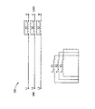
도 2는 본 발명의 일 실시예에 따른 구동 시스템에서 트랜스포머와 관련 스위치들의 회로도이다.2 is a circuit diagram of a transformer and associated switches in a drive system according to an embodiment of the invention.
도 3a 및 도 3b는 최저 전압이 얻어지는 제1 구성에 대한 도 2의 회로 접속부와 페이저 도(phasor diagram)를 각각 도시한다.3A and 3B show the circuit connection and phasor diagram of FIG. 2, respectively, for the first configuration in which the lowest voltage is obtained.
도 4a 및 도 4b는 제1 고 전압이 얻어지는 제2 구성에 대한 도 2의 회로 접속부와 페이저 도를 각각 도시한다.4A and 4B show the circuit connection and pager diagrams of FIG. 2, respectively, for a second configuration in which a first high voltage is obtained.
도 5a 및 도 5b는 제2 고 전압이 얻어지는 제3 구성에 대한 도 2의 회로 접속부와 페이저 도를 각각 도시한다.5A and 5B show the circuit connection and pager diagrams of FIG. 2, respectively, for a third configuration in which a second high voltage is obtained.
도 6a 및 도 6b는 라인 전압이 모터에 전달되는 제4 구성에 대한 도 2의 회로 접속부와 페이저 도를 각각 도시한다.6A and 6B show the circuit connection and pager diagrams of FIG. 2, respectively, for a fourth configuration in which line voltage is delivered to the motor.
도 7은 본 발명의 일 실시예에 따른 구동 시스템에서 트랜스포머와 관련 스위치들의 회로도이다.7 is a circuit diagram of a transformer and associated switches in a drive system according to an embodiment of the invention.
도 8은 본 발명의 다른 실시예에 따른 구동 시스템에서 트랜스포머와 관련 스위치들의 회로도이다.8 is a circuit diagram of a transformer and associated switches in a drive system according to another embodiment of the invention.
도 9는 모터 상의 부하에 전압을 정합하는 유도 모터의 전압의 제어 방법의 흐름도이다.9 is a flowchart of a method of controlling the voltage of an induction motor that matches a voltage with a load on the motor.
도 1은 본 발명의 일 실시예에 따른 모터(102)에 전력을 공급하는 전력 제어기(구동 시스템)(100)의 개략 회로도이다. 도시한 바와 같이, 전력 제어기(100)는 제1 전압에서 상(L1, L2 및 L3)에서 3상 전력을 수신하고, 상(U, V, W)에서 가변 출력 전압에서 모터(100)에 전력을 전달한다. 모터는 부하(104)를 구동한다. 뉴트럴(N)은 모터에 공급될 수 있다. 제어기(106)는 전력 제어기의 동작을 제어하고, 이하 기술하는 바와 같이, 임의의 측정 모듈(108)로부터 입력에 응답할 수 있다.1 is a schematic circuit diagram of a power controller (drive system) 100 for supplying power to a
도 2는 본 발명의 일례의 실시예에서 전력 제어기(100)의 회로의 임의의 구성을 도시한다. 가장 간단한 형태에 있어서, 전력 제어기는 P1, P2 및 P3으로서 지정된 1차 권선, 및 2차 권선(S1, S2 및 S3)을 갖는 3상 트랜스포머를 포함한다. 2차 권선은 라인 입력들과 부하 사이에 직렬 접속되어 있다. 또한, 전력 제어기는 다른 방식으로 라인 입력들에 걸쳐 1차 권선들을 접속하는데 효과적인 복수의 3상 스위치들(K1, K2, K3 및 K4)을 포함한다.2 illustrates any configuration of a circuit of
또한, 임의의 상황하에서 2차 권선을 단락 회로로 하는데 임의의 3상 스위치(K6)가 사용된다.Also, any three-phase switch K6 is used to short circuit the secondary winding under any circumstances.
스위치들의 주 구성은 이하의 도면에 도시되어 있다.The main configuration of the switches is shown in the following figure.
도 3a 및 3b는 최저 전압이 부하에 전달되는 제1 구성에 대한 도 2의 회로의 접속부와 벡터 도를 각각 도시한다.3a and 3b show the connection and the vector diagram of the circuit of FIG. 2, respectively, for the first configuration in which the lowest voltage is delivered to the load.
도 3a는 K1과 K3이 폐쇄되고, 다른 스위치들이 개방된 경우 도 2의 회로를 도시한다. 이 구성에서, P1은 라인 상(1과 2) 사이에 접속되고, P2는 라인 상(2와 3) 사이에 접속되고, P3는 라인 상(3과 1) 사이에 접속된다.3A shows the circuit of FIG. 2 when K1 and K3 are closed and other switches are open. In this configuration, P1 is connected between the
1차 권선들에 인가된 전압의 상이 2차 권선이 접속된 라인과 30°이상(out of phase)되므로, 도 3b에 도시된 상 도면이 얻어진다. 본 발명의 한정이 아닌 예시로서 1차 2차 권선비를 400/100로 하고, 입력 전압은 400볼트인 것으로 한다.Since the phase of the voltage applied to the primary windings is out of phase with the line to which the secondary winding is connected, the phase diagram shown in FIG. 3B is obtained. By way of example and not limitation, the primary secondary turns ratio is set to 400/100 and the input voltage is set to 400 volts.
도시한 권선 방향의 경우에, 결과적인 상 대 상 출력 전압(U,V,W)는 253볼트이다.In the case of the winding direction shown, the resulting relative output voltages (U, V, W) are 253 volts.
도 4a 및 4b는 다음 높은 전압이 부하에 전달된 제2 구성에 대한 도 2 회로의 접속부와 페이저 도를 각각 도시한다.4A and 4B show the connections and pager diagrams of the FIG. 2 circuit, respectively, for a second configuration in which the next high voltage is delivered to the load.
도 4a는 스위치들(K1 및 K4)이 폐쇄되고, 다른 스위치들이 개방된 도 2의 회로를 도시한다. 이 구성에서, P1, P2 및 P3 각각은 그 자체 상과 뉴트럴 사이에 접속되어 있다. 또한, 접속부는 실제 뉴트럴 또는 같은 점에 대한 트랜스포머들의 일단부의 접속부에 의해 형성된 뉴트럴(N')로 될 수 있다.FIG. 4A shows the circuit of FIG. 2 with switches K1 and K4 closed and other switches open. In this configuration, each of P1, P2 and P3 is connected between itself and neutral. Also, the connection can be a neutral N 'formed by the connection of one end of the transformers to the actual neutral or the same point.
1차 권선들에 인가된 전압의 위상이 2차 권선이 접속된 라인과 동상이므로, 도 4b에 도시된 상 도면이 얻어진다. 본 발명의 한정이 아닌 예시로서, 400/100를 1차 2차 권선비로 하고, 입력 전압은 400볼트로 한다. P 권선 각각의 전압이 253볼트이므로, 2차 전압은 63볼트로 입력 라인 전압과 이상 된다. 상 대 상 전압(U, V, W)은 289V이다.Since the phase of the voltage applied to the primary windings is in phase with the line to which the secondary winding is connected, the phase diagram shown in FIG. 4B is obtained. By way of example and not limitation, 400/100 is the primary secondary winding ratio and the input voltage is 400 volts. Since the voltage on each of the P windings is 253 volts, the secondary voltage is 63 volts and above the input line voltage. The relative target voltages (U, V, W) are 289V.
도 3a와 도 4a의 구성 사이에서 절환시(접속 이전에 브레이크가 바람직함) 2차 권선들이 순간적으로 고 임피던스를 제공하여도 1차 권선이 개방회로가 되므로 모터로의 전류는 차단되지 않는다. 또한 스누버 또는 다른 스파이크 감소 회로가 1차 권선들에 걸쳐 배치된다.When switching between the configurations of Figs. 3A and 4A (preferably brake before connection), even if the secondary windings provide instantaneously high impedance, the current to the motor is not interrupted since the primary winding is an open circuit. A snubber or other spike reduction circuit is also placed over the primary windings.
도 5a 및 5b는 다음 높은 전압이 부하에 전달되는 제3 구성에 대한 도 2의 회로의 접속부와 페이저 도를 각각 도시한다.5A and 5B show the connection and pager diagrams of the circuit of FIG. 2, respectively, for a third configuration in which the next high voltage is delivered to the load.
도 5a는 스위치(K2 및 K3)가 폐쇄되고, 다른 스위치들이 개방되는 경우 도 2의 회로를 도시한다. 이 구성에서, P1, P2 및 P3 각각은 다른 상과 뉴트럴 사이에 접속되어 있다.5a shows the circuit of FIG. 2 when switches K2 and K3 are closed and other switches are open. In this configuration, each of P1, P2 and P3 is connected between the other phase and the neutral.
각각의 1차 권선에 인가된 전압의 상이 2차 권선이 접속된 라인과 60°이상되므로, 도 5b에 도시한 상 도면이 얻어진다. 본 발명의 한정이 아닌 예시로서 400/100를 1차 2차 권선비로 하고, 입력 전압을 400볼트로 한다. P 권선 각각의 전압이 253볼트이므로, 2차 전압은 63볼트이다. 그래서 상 대 상 전압(U, V, W)은 356볼트이다.Since the phase of the voltage applied to each primary winding is 60 ° or more with the line to which the secondary winding is connected, the phase diagram shown in FIG. 5B is obtained. By way of example and not limitation, 400/100 is the primary secondary winding ratio, and the input voltage is 400 volts. Since the voltage of each of the P windings is 253 volts, the secondary voltage is 63 volts. So the relative voltages (U, V, W) are 356 volts.
도 6a 및 6b는 입력 라인 전압이 부하에 전달된 제4 구성에 대한 도 2 회로의 접속부와 페이저 도를 각각 도시한다.6A and 6B show the connections and pager diagrams of the FIG. 2 circuit, respectively, for a fourth configuration in which input line voltage is delivered to the load.
도 6a는 K6가 임의로 폐쇄된 것을 제외하고, 스위치들(K2 및 K4)이 폐쇄되고, 다른 스위치들이 개방된 경우의 도 2의 회로를 도시한다. 이 구성에서, P1, P2 및 Ps 각각은 라인으로부터 단절되고 단락되며, 2차 권선들이 또한 임의로 단락된다. 따라서 실제적인 전압이 입력 라인 전압과 반대로 되고, 즉, 400볼트가 모터에 직접적으로 인가된다.FIG. 6A shows the circuit of FIG. 2 when switches K2 and K4 are closed and other switches are open, except that K6 is optionally closed. In this configuration, each of P1, P2 and Ps is disconnected and shorted from the line, and the secondary windings are also optionally shorted. Thus the actual voltage is reversed to the input line voltage, i.e. 400 volts is applied directly to the motor.
2차 권선들을 단락하는 것이 절대적으로 필요하지 않음을 이해해야 한다. 그러나 2차 권선들은 트랜스포머에서 코어 및/또는 도전 손실을 방지하도록 바람직하게 단락되어야 한다.It should be understood that it is not absolutely necessary to short the secondary windings. However, the secondary windings should preferably be shorted to prevent core and / or conduction losses in the transformer.
소수의 전압 스텝이 필요한 경우, 1차 측의 스위치들의 수는 감소될 수 있 다. 예를 들어, K3 및 K4가 단락 회로로 대체되는 경우, K1을 폐쇄하면서 K2 및 K6를 개방으로 유지하는 것이 도 3a의 구성을 가져오고 부하에 253볼트의 전압을 공급한다. K1을 개방하고, K2를 단락하고 그리고 임의로 K6를 단락하면 도 6a의 구성이 생성되고, 입력 라인 전압이 부하에 전달된다.If fewer voltage steps are needed, the number of switches on the primary side can be reduced. For example, if K3 and K4 are replaced by a short circuit, keeping K2 and K6 open while closing K1 results in the configuration of FIG. 3A and provides a load of 253 volts to the load. Opening K1, shorting K2, and optionally shorting K6 creates the configuration of FIG. 6A and transfers the input line voltage to the load.
따라서 본 발명은 예를 들어 유도 모터를 시동하는 경우와 같이 부하에 라인 전압의 전압 이하 또는 그 전압과 같은 전압들을 제공하는 것과 관련하여 기술하였다. 그러나 트랜스포머(또는 1차 또는 2차 접속부) 상의 권선이 역전되는 경우 예를 들어, 1차 권선의 접속부를 반전함으로써 라인 전압보다 높은 하나 이상의 전압을 부하에 제공하는데 유사 구성이 사용될 수 있다. 이러한 구성은 시동을 위해 구동 전압보다 높은 전압이 필요하거나 또는 많은 전압 스텝들이 바람직한 것으로 생각되는 경우에 유용할 수 있다. 중간 스텝들을 제공하는 데는 많은 스위치들을 필요로 할 수 있다.Accordingly, the present invention has been described with respect to providing voltages below or equal to the line voltage, such as when starting an induction motor, for example. However, similar configurations can be used to provide the load with one or more voltages higher than the line voltage, for example, by reversing the connections of the primary winding when the windings on the transformer (or primary or secondary connections) are reversed. This configuration may be useful if a voltage higher than the drive voltage is needed for start-up or if many voltage steps are deemed desirable. Providing intermediate steps may require many switches.
유사하게, 또한 중간 전압이 예를 들어 2차 권선과는 다른 상 사이에 1차 권선들을 접속함으로써 다른 방식으로 1차 권선을 절환함으로써 얻어질 수 있다. 그러나 도시한 바람직한 실시예들에서, 모든 절환은 저 전류 측에 있으며, 메인 전류 경로에 스위치들이 없음을 지적한다.Similarly, an intermediate voltage can also be obtained by switching the primary winding in a different way, for example by connecting the primary windings between a phase different from the secondary winding. However, in the preferred embodiments shown, all switching is on the low current side, indicating that there are no switches in the main current path.
전술한 그리고 도 2-6에 도시된 실시예(100)에서, 1차 권선들은 입력 라인들에 걸쳐 직접적으로 접속되고, 2차 권선들이 1차 권선의 병렬 접속부의 부하 측에 직렬 접속되어 있다. 본 발명의 다른 실시예들에서, 2차 권선들은 라인 측에 접속되고, 1차 권선들의 병렬 접속부는 2차 권선들 이후에 부하 측에 있다.In the
도 7은 전력 제어기(200)의 경우에 접속을 도시하는데, 권선들 및 스위치들에 대한 참조부호 각각은 도 2와 같다. 전력 제어기(200)의 동작은 전력 제어기(100)의 동작과 유사하고, 같은 절환이 전술한 것과 같은 전압에서 얻어진다. 본 발명의 일부 실시예들에서, 제어기(200)는 도 1의 제어기(100)를 대체한다.FIG. 7 shows a connection in the case of the
본 발명의 일부의 실시예들에서, 부하가 감소되는 경우 유도 모터 또는 다른 부하에서 전압을 정합하는 것이 목적이다. 유도 모터의 경우에, 임의의 소정의 기계적 부하에 있어서, 회전 속도 및 유도 전류는 기계적 부하와 일치하도록 그 자체를 자동으로 조정한다. 부하가 감소될 때, 속도가 동기 속도와 가까워지고, 전류가 하강하도록 역율 및 효율 강하와 더불어 속도가 상승한다. 본 발명의 일 실시예에서, 인가된 전압은 모터가 이 입력 전압의 경우 전 정격 전류 및 전압에서 동작하도록 조정된다.In some embodiments of the invention, it is an object to match the voltage in an induction motor or other load when the load is reduced. In the case of an induction motor, for any given mechanical load, the rotational speed and induction current automatically adjust itself to match the mechanical load. As the load decreases, the speed approaches the synchronous speed, and the speed rises with power factor and efficiency drop so that the current falls. In one embodiment of the invention, the applied voltage is adjusted so that the motor operates at full rated current and voltage in the case of this input voltage.
본 발명의 또 다른 실시예에 있어서, 각 1차 권선의 한쪽은 2차 권선의 한쪽에서 접속되고, 1차 권선의 다른 쪽은 2차 권선의 부하 쪽에서 접속된다.In another embodiment of the present invention, one side of each primary winding is connected at one side of the secondary winding and the other side of the primary winding is connected at the load side of the secondary winding.
도 8은 전력 제어기(300)의 경우에 이러한 접속을 도시하는데, 권선들 및 스위치들에 대한 참조번호들 각각은 도 2와 같다. 전력 제어기(300)의 동작은 전력 제어기(100)의 동작과 유사하여 같은 절환이 전술한 바와 같이 같은 전압을 생성한다. 본 발명의 일부 실시예들에서, 제어기(300)는 도 1의 제어기(100)를 대체한다.FIG. 8 shows this connection in the case of the
도 7 및 8의 실시예들의 동작은 일반적으로 도 2의 동작과 유사하지만, 전압(및 바람직한 변압비)는 본 발명의 이용에 따라 다소 다르다. 예를 들어, 도 7 의 실시예의 경우에, 230V 정격의 1차 권선 및 110V 정격의 2차 권선에서 출력 전압은 K1,K3;K1,K4;K2,K3; 및 K2,K4 및 K6를 각각 단락시키도록 220V, 250V, 300V 및 400V이다. 예를 들어, 도 8의 실시예의 경우에, 280V 정격의 1차 권선 및 120V 정격의 2차 권선에서 출력 전압은 K1,K3;K1,K4;K2,K3; 및 K2,K4 및 K6를 각각 단락시키도록 230V, 260V, 320V 및 400V이다. 모두 3개의 실시예의 경우에, 1차/2차 권선비의 넓은 선택을 활용할 수 있으며, 여러 스텝들에서 각종의 전압 값들을 제공하도록 조정될 수 있음을 강조한다.The operation of the embodiments of FIGS. 7 and 8 is generally similar to that of FIG. 2, but the voltage (and preferred transformer ratio) is somewhat different depending on the use of the present invention. For example, in the case of the embodiment of Fig. 7, the output voltages in the primary winding of 230V rating and the secondary winding of 110V rating are K1, K3; K1, K4; K2, K3; And 220V, 250V, 300V and 400V to short-circuit K2, K4 and K6, respectively. For example, in the case of the embodiment of FIG. 8, the output voltages in the primary winding of 280V rating and the secondary winding of 120V rating are K1, K3; K1, K4; K2, K3; And 230V, 260V, 320V and 400V to short K2, K4 and K6, respectively. It is emphasized that in the case of all three embodiments, a wide selection of primary / secondary turns ratios can be utilized and can be adjusted to provide various voltage values at different steps.
전압의 조정은 모터의 RPM의 측정, 또는 유도 전류 또는 전류의 상에 응답하여 자동으로 만들어질 수 있다.The adjustment of the voltage can be made automatically in response to the measurement of the RPM of the motor, or the induced current or phase of the current.
도 1을 다시 참조하면, 측정 모듈(108)은 모터(102)의 부하의 하나 이상의 표시기들을 측정하는데 사용된다. 이러한 표시기들은 모터 내의 전력, 모터에 대한 전력 입력의 (전압에 대한) 전류의 상, 모터 및 전류의 회전 비율을 포함한다. 또한, 모터의 전기적 특성들은 전력 제어기의 업스트림에서 측정될 수 있다.Referring again to FIG. 1, the
이들 표시기들 각각은 모터가 기계적 부하에서 적절한 전압에서 동작하는지 여부 또는 모터에 전달된 전압이 최적의 효율적인 동작을 위해 너무 높은지 여부를 액세스하는데 사용될 수 있다.Each of these indicators can be used to access whether the motor is operating at an appropriate voltage at a mechanical load or whether the voltage delivered to the motor is too high for optimal efficient operation.
특히, 모터에 대한 전력 입력이 임의의 소정의 입력 전압에 대해 소정의 스레숄드 이하에 있는 경우, 동일한 기계적 부하를 공급하도록 전압이 안전하게 감소될 수 있다고(전류의 증가의 수반과 더불어) 가정할 수 있다. 전류의 위상이 소정의 값 이상만큼 전압의 상에 뒤처지는 경우, 동일한 가정에 이를 수 있다. 유사하 게, 모터의 동기 속도에 대한 임의 값에 가까운 회전 속도는 모터가 모터에 대한 입력 전압에서 언더 로드되는(under loaded) 것을 나타낸다.In particular, it can be assumed that when the power input to the motor is below a certain threshold for any given input voltage, the voltage can be safely reduced (with an increase in current) to supply the same mechanical load. . If the phase of the current lags behind the phase of the voltage by more than a predetermined value, the same assumption can be reached. Similarly, a rotational speed close to any value for the motor's synchronous speed indicates that the motor is under loaded at the input voltage to the motor.
이들 각각의 경우에, 제어기(106)는 모터가 다음 이용가능 전압에서 필요한 전력을 전달할 수 있고, 아직 모터의 특성인 전류 제한 내에 있는지 여부를 결정한다. 그런 경우, 전력 제어기(100)에 의해 공급된 전압은 이용가능한 다음 낮은 전압으로 조정될 수 있다. 유사하게 제어기(106)는 측정 모듈(108)에 의해 공급된 동작 특성들을 기반으로 모터가 공급되는 전압에서 달성할 수 있는 최고의 전력에 가까이 있다고 결정할 수 있다. 이 경우, 제어기(106)는 모터에 높은 전압을 공급하도록 전력 제어기(100, 200, 또는 300)의 스위치 패턴들을 변화시킬 수 있다.In each of these cases, the
도 9는 모터 상의 부하에 전압을 정합하도록 유도 모터의 전압을 제어하는 방법(700)에 대한 흐름도이다. 702에서, 모터 특성들이 결정된다. 704에서 모터 특성들은 전술한 바와 같이 전압이 증가 또는 감소되는지 여부를 결정하기 위한 기준과 비교된다. 전압이 부하에 대해 "정확한" 전압인 경우, 모듈(108) 및 제어기(106)는 계속해서 전압의 변화가 바람직한지를 모니터한다. 전압이 감소될 수 있는 것으로 결정된 경우, 전압은 감소된다(706). 전압이 증가되어야 하는 것으로 결정된 경우, 전압은 증가된다(708). 각 경우에, 특성들은 전압이 적당한지를 결정하도록 모니터된다.9 is a flowchart of a
또한 제어기(106)는 모터의 동작 특성에 관한 정보를 갖고 있어서 이들 특성을 모터를 다음 높은 또는 낮은 전압으로 절환할지를 결정하는데 이용한다.The
모터를 시동하는 경우, 모터 동작 특성들의 측정은 모터가 필요로 하는 전력 을 공급하도록 모터가 최고의 이용가능한 전압을 필요로 하지 않는다는 것을 나타낼 수 있음은 물론이다. 이러한 상황하에서, 높은 전압에 대한 하나 이상의 절환 동작들은 임의로 수행되지 않는다.Of course, when starting the motor, measurement of motor operating characteristics may indicate that the motor does not need the highest available voltage to supply the power needed by the motor. Under this situation, one or more switching operations for the high voltage are not arbitrarily performed.
모터 동작 특성들을 기초로 모터에 공급된 전압을 감소 또는 제어하기 위한 전력 제어기의 사용이 전술한 바와 같이, 전력 제어기(100, 200 또는 300)를 이용하여 설명할 수 있지만, 이 기술에 알려진 다른 전력 제어기가 이 목적을 위해 사용될 수 있다.The use of a power controller to reduce or control the voltage supplied to the motor based on the motor operating characteristics can be described using the
본 발명의 일부 실시예들에서, 전압을 절환하는 경우를 결정하도록 모터 특성들을 모니터하는 것이 바람직하지만, 소정의 절환 이후 또는 입력 전류가 임의의 값 또는 그 최초 값의 퍼센트 이하로 강하한 이후 소정 시간 동안 발생하는 절환과 더불어 모터의 시동 동안 절환이 자동으로 수행될 수 있음은 물론이다. 이 경우 제어기는 타이머 또는 단일 전류 측정 장치로 되는 것이 고려될 수 있다.In some embodiments of the invention, it is desirable to monitor motor characteristics to determine when to switch voltages, but after a predetermined switch or a predetermined time after the input current drops below a certain value or a percentage of its initial value. It is, of course, possible that the switching can be carried out automatically during the starting of the motor, along with the switching that takes place during the operation. In this case, the controller may be considered to be a timer or a single current measuring device.
전술한 방법들은 단계들의 순서를 변경, 및/또는 복수의 단계들의 수행을 포함한 많은 방식으로 동시에 변화될 수 있음은 물론이다. 또한, 방법 및 장치들의 전술한 설명은 방법들을 수행하는 장치 및 장치를 이용한 방법들로서 해석되어야 함은 물론이다. 본 발명은 본 발명의 영역의 한정의 목적이 아닌 일례로서 제공된 본 발명의 실시예들의 비 제한적인 상세한 설명을 이용하여 기술하였다. 실시예와 관련하여 기술한 특징들 및/또는 단계들은 다른 실시예들과 함께 사용될 수 있으며, 본 발명의 모든 실시예가 특정 도면에 도시되거나 실시예들 중 하나와 관련하여 기술한 특징들 및/또는 단계들을 모두를 포함하지는 않음은 물론이다. 기술한 실시예들의 변형이 이 기술의 당업자에 의해 수행될 수 있다. 또한, 용어 "포함하다(comprise)", "포함하다(include)", "갖다" 및 이들의 언어적 변형들은 청구범위에서 사용되는 경우 "어떤 것으로 반드시 한정이 아닌 포함"을 의미한다.It goes without saying that the foregoing methods can be varied simultaneously in many ways, including by changing the order of the steps and / or by performing a plurality of steps. Moreover, it is to be understood that the foregoing description of the methods and apparatuses is to be construed as an apparatus for performing the methods and methods using the apparatus. The invention has been described using a non-limiting detailed description of embodiments of the invention provided as an example and not as a limitation of the scope of the invention. Features and / or steps described in connection with an embodiment may be used in conjunction with other embodiments, and all embodiments of the invention are shown in a particular drawing or described in connection with one of the embodiments and / or Of course, not all of the steps are included. Modifications of the described embodiments can be carried out by those skilled in the art. Also, the terms "comprise", "include", "have", and their linguistic variations, as used in the claims, mean "including, but not necessarily limited to," what is.
전술한 실시예들 중 일부는 발명자들이 생각하는 최적 모드를 기술하므로, 구조, 동작 또는 본 발명에 필수적이지 않을 수 있는 예로서 기술한 구조 및 동작의 구성을 포함할 수 있음을 지적한다. 여기에 기술된 구조 및 동작은 그 구조 또는 동작이 이 기술에 알려진 것과 다른 것일 지라도 같은 기능을 수행하는 등가물로 대체될 수 있다. 따라서 본 발명의 영역은 청구범위에서 사용된 요소들 및 제한들로만 한정된다.It is pointed out that some of the embodiments described above may include the structure, operation, or configuration of the operation described as an example that may not be essential to the present invention, since it describes the best mode contemplated by the inventors. The structures and operations described herein may be replaced with equivalents that perform the same function even if the structures or operations are different from those known in the art. Thus, the scope of the present invention is limited only by the elements and limitations used in the claims.
Claims (23)
Applications Claiming Priority (4)
| Application Number | Priority Date | Filing Date | Title |
|---|---|---|---|
| US83123806P | 2006-07-17 | 2006-07-17 | |
| US60/831,238 | 2006-07-17 | ||
| IL179284A IL179284A0 (en) | 2006-07-17 | 2006-11-14 | Power control |
| IL179284 | 2006-11-14 |
Publications (1)
| Publication Number | Publication Date |
|---|---|
| KR20090031762A true KR20090031762A (en) | 2009-03-27 |
Family
ID=38793005
Family Applications (1)
| Application Number | Title | Priority Date | Filing Date |
|---|---|---|---|
| KR1020097002419A KR20090031762A (en) | 2006-07-17 | 2007-07-16 | Variable voltage supply system |
Country Status (13)
| Country | Link |
|---|---|
| US (1) | US8159175B2 (en) |
| EP (2) | EP2164168A2 (en) |
| JP (1) | JP2009544271A (en) |
| KR (1) | KR20090031762A (en) |
| AT (1) | ATE452463T1 (en) |
| AU (1) | AU2007274573A1 (en) |
| CA (1) | CA2657661A1 (en) |
| DE (1) | DE602007003845D1 (en) |
| DK (1) | DK2044684T3 (en) |
| ES (1) | ES2338607T7 (en) |
| IL (1) | IL196537A (en) |
| MX (1) | MX2009000642A (en) |
| WO (1) | WO2008010213A2 (en) |
Families Citing this family (6)
| Publication number | Priority date | Publication date | Assignee | Title |
|---|---|---|---|---|
| EP2164168A2 (en) | 2006-07-17 | 2010-03-17 | PowerSines Ltd. | Variable voltage supply system |
| WO2009107130A1 (en) * | 2008-02-25 | 2009-09-03 | Power Electronics Systems (2006) Ltd. | Power system for air conditioning systems |
| WO2011024167A1 (en) | 2009-08-26 | 2011-03-03 | Powersines Ltd. | System and method for controlling voltage, useful for controlling the voltage at the user site |
| US8878468B2 (en) * | 2011-04-29 | 2014-11-04 | Pratt & Whitney Canada Corp. | Electric machine assembly with fail-safe arrangement |
| AU2011369270A1 (en) * | 2011-05-24 | 2013-11-14 | Siemens Aktiengesellschaft | Electrical feeding device |
| DE102015102727A1 (en) * | 2015-02-25 | 2016-08-25 | Maschinenfabrik Reinhausen Gmbh | Method for changing the active number of turns of a control winding in an electrical system and electrical system with a control winding |
Family Cites Families (31)
| Publication number | Priority date | Publication date | Assignee | Title |
|---|---|---|---|---|
| DE383419C (en) | 1923-10-13 | Rudolf Richter | Electrical control system | |
| GB544312A (en) | 1939-10-30 | 1942-04-08 | British Thomson Houston Co Ltd | Improvements in transformer voltage regulating systems |
| DE2034638A1 (en) | 1970-07-13 | 1972-01-20 | Transformatorenwerk August Lep | Arrangement of a step regulating winding for 90 degree cross regulation with star and open circuit in three-phase transformers |
| JPS5627138B2 (en) * | 1973-04-09 | 1981-06-23 | ||
| NL7414021A (en) | 1974-10-25 | 1976-04-27 | Smit Nijmegen Bv | ADJUSTABLE MULTI-PHASE TRANSFORMER SYSTEM FOR CONNECTING TWO DISTRIBUTION NETWORKS. |
| US4219759A (en) | 1978-09-25 | 1980-08-26 | Hirschfeld Richard L | Three phase power control unit |
| DE2933685A1 (en) | 1979-07-25 | 1981-02-12 | Bbc Brown Boveri & Cie | TRANSFORMER FOR CONTROLLED SHIFTING OF THE PHASE ANGLE OF THE OUTPUT VOLTAGES AGAINST THE PHASE ANGLE OF THE INPUT VOLTAGES |
| SU1170567A1 (en) | 1983-03-11 | 1985-07-30 | Вологодский Политехнический Институт | Controlled m-phase converter of a.c.voltage to a.c.voltage |
| US4860145A (en) * | 1983-11-14 | 1989-08-22 | Oneac Corporation | Tap switching protection circuit |
| JPS6335187A (en) * | 1986-07-28 | 1988-02-15 | Hitachi Ltd | Control device of induction motor |
| JPH0295186A (en) * | 1988-09-29 | 1990-04-05 | Japan Araamu Syst Kk | Controller for ac motor |
| JPH0370100U (en) * | 1989-11-13 | 1991-07-12 | ||
| SU1758821A1 (en) | 1990-02-21 | 1992-08-30 | Уральский политехнический институт им.С.М.Кирова | A c electric drive |
| JPH03270685A (en) * | 1990-03-16 | 1991-12-02 | Hitachi Ltd | Controller for induction motor |
| JPH077978A (en) * | 1993-06-17 | 1995-01-10 | Meidensha Corp | Korndorfer method for starting motor |
| US5557249A (en) * | 1994-08-16 | 1996-09-17 | Reynal; Thomas J. | Load balancing transformer |
| EP0774830B1 (en) | 1995-10-20 | 2002-06-05 | Lg Electronics Inc. | Apparatus for controlling a compressor in a cooling system |
| US5952790A (en) * | 1996-09-06 | 1999-09-14 | General Electric Company | Lamp ballast circuit with simplified starting circuit |
| US6014323A (en) * | 1997-08-08 | 2000-01-11 | Robicon Corporation | Multiphase power converter |
| DE19923237A1 (en) * | 1999-05-20 | 2000-11-23 | Patent Treuhand Ges Fuer Elektrische Gluehlampen Mbh | Circuit arrangement, associated electrical system and discharge lamp with such a circuit arrangement and method for its operation |
| US6351106B1 (en) | 2000-09-29 | 2002-02-26 | Silicon Power Corporation | Static voltage regulator and controller |
| ES2179764B2 (en) * | 2001-02-23 | 2003-10-01 | Univ Pontificia Comillas | VOLTAGE STABILIZER FOR TRANSPORTATION APPLICATIONS AND DISTRIBUTION OF ELECTRICAL ENERGY. |
| JP4031257B2 (en) * | 2002-02-15 | 2008-01-09 | 三菱電機株式会社 | AC motor control device |
| EP1341295A1 (en) | 2002-02-27 | 2003-09-03 | Jakob, Karl, Dipl.-Ing.(FH) | Power supply circuit for a three-phase motor |
| JP2004088929A (en) | 2002-08-27 | 2004-03-18 | Toshiba Corp | Voltage imbalance reduction device |
| JP3774208B2 (en) * | 2003-05-16 | 2006-05-10 | 株式会社エヌ・ティ・ティ・データ・イー・エックス・テクノ | AC voltage controller |
| JP2005143266A (en) * | 2003-11-10 | 2005-06-02 | Toyo Riken Kk | Three-phase induction motor driving method and driving device used therein |
| US6954366B2 (en) * | 2003-11-25 | 2005-10-11 | Electric Power Research Institute | Multifunction hybrid intelligent universal transformer |
| US7394397B2 (en) * | 2004-01-17 | 2008-07-01 | Hap Nguyen | Standby loss prevention module, transformer system including same, and methods relating thereto |
| EP2164168A2 (en) | 2006-07-17 | 2010-03-17 | PowerSines Ltd. | Variable voltage supply system |
| WO2011024167A1 (en) | 2009-08-26 | 2011-03-03 | Powersines Ltd. | System and method for controlling voltage, useful for controlling the voltage at the user site |
-
2007
- 2007-07-16 EP EP09175040A patent/EP2164168A2/en not_active Withdrawn
- 2007-07-16 DK DK07789948.2T patent/DK2044684T3/en active
- 2007-07-16 MX MX2009000642A patent/MX2009000642A/en active IP Right Grant
- 2007-07-16 DE DE602007003845T patent/DE602007003845D1/en active Active
- 2007-07-16 AT AT07789948T patent/ATE452463T1/en not_active IP Right Cessation
- 2007-07-16 EP EP07789948A patent/EP2044684B3/en active Active
- 2007-07-16 CA CA002657661A patent/CA2657661A1/en not_active Abandoned
- 2007-07-16 ES ES07789948T patent/ES2338607T7/en active Active
- 2007-07-16 JP JP2009520128A patent/JP2009544271A/en active Pending
- 2007-07-16 US US12/373,744 patent/US8159175B2/en active Active
- 2007-07-16 WO PCT/IL2007/000892 patent/WO2008010213A2/en active Application Filing
- 2007-07-16 KR KR1020097002419A patent/KR20090031762A/en not_active Application Discontinuation
- 2007-07-16 AU AU2007274573A patent/AU2007274573A1/en not_active Abandoned
-
2009
- 2009-01-15 IL IL196537A patent/IL196537A/en active IP Right Grant
Also Published As
| Publication number | Publication date |
|---|---|
| US8159175B2 (en) | 2012-04-17 |
| US20090309536A1 (en) | 2009-12-17 |
| EP2164168A2 (en) | 2010-03-17 |
| ES2338607T3 (en) | 2010-05-10 |
| ATE452463T1 (en) | 2010-01-15 |
| EP2044684B3 (en) | 2012-12-26 |
| CA2657661A1 (en) | 2008-01-24 |
| IL196537A (en) | 2012-05-31 |
| EP2044684A2 (en) | 2009-04-08 |
| DE602007003845D1 (en) | 2010-01-28 |
| MX2009000642A (en) | 2009-07-02 |
| AU2007274573A1 (en) | 2008-01-24 |
| IL196537A0 (en) | 2009-11-18 |
| DK2044684T3 (en) | 2010-04-26 |
| EP2044684B1 (en) | 2009-12-16 |
| WO2008010213A2 (en) | 2008-01-24 |
| ES2338607T7 (en) | 2013-04-23 |
| JP2009544271A (en) | 2009-12-10 |
| WO2008010213A3 (en) | 2008-04-03 |
Similar Documents
| Publication | Publication Date | Title |
|---|---|---|
| CN108292902B (en) | Hybrid drive circuit and control method for variable speed induction motor system | |
| JPH05252747A (en) | Voltage regulator | |
| KR20090031762A (en) | Variable voltage supply system | |
| US8207716B2 (en) | Useful improvements in the art of 3-phase electronic tap changer commutation device | |
| CN111247735B (en) | Motor driving device | |
| EP0849655A2 (en) | Alternating current power control device | |
| US8030870B2 (en) | Method and device for reducing the influence of a DC component in a load current of an asynchronous three-phase motor | |
| US7737667B2 (en) | 3-phase electronic tap changer commutation and device | |
| EP1054502A1 (en) | Alternating current power supply with electronically regulated voltage | |
| WO1997002518A1 (en) | Voltage regulator | |
| US20240136961A1 (en) | Control of motor soft starter using power electronic switching devices | |
| KR20040076376A (en) | Start control circuit of hybrid motor starter | |
| JP3764011B2 (en) | Permanent magnet synchronous motor controller | |
| WO2022171365A1 (en) | Control of motor soft starter using power electronic switching devices | |
| JP2022117269A (en) | Ac power generator | |
| US10411585B2 (en) | Inverter system, inverter apparatus, and method of controlling inverter system | |
| JP2003050638A (en) | Voltage controller | |
| BRPI0713176A2 (en) | "Mechanism for controlling the voltage supplied to a load, method for varying the voltage at a load and method for varying the voltage for an induction motor" | |
| JP2006081292A (en) | Voltage regulator | |
| WO2009107130A1 (en) | Power system for air conditioning systems | |
| JPH0759273A (en) | Low-voltage uninterruptible change-over device | |
| KR20180015840A (en) | Electric power saver with automatic tap adjustment function | |
| JPS63245297A (en) | Scherbius equipment | |
| JPH08126325A (en) | Rectifier | |
| JPH10254561A (en) | Power-saving device |
Legal Events
| Date | Code | Title | Description |
|---|---|---|---|
| WITN | Application deemed withdrawn, e.g. because no request for examination was filed or no examination fee was paid |