JP7435560B2 - power system - Google Patents
power system Download PDFInfo
- Publication number
- JP7435560B2 JP7435560B2 JP2021133402A JP2021133402A JP7435560B2 JP 7435560 B2 JP7435560 B2 JP 7435560B2 JP 2021133402 A JP2021133402 A JP 2021133402A JP 2021133402 A JP2021133402 A JP 2021133402A JP 7435560 B2 JP7435560 B2 JP 7435560B2
- Authority
- JP
- Japan
- Prior art keywords
- battery
- power
- sweep unit
- output
- power supply
- Prior art date
- Legal status (The legal status is an assumption and is not a legal conclusion. Google has not performed a legal analysis and makes no representation as to the accuracy of the status listed.)
- Active
Links
- HBBGRARXTFLTSG-UHFFFAOYSA-N Lithium ion Chemical compound [Li+] HBBGRARXTFLTSG-UHFFFAOYSA-N 0.000 claims description 18
- 229910001416 lithium ion Inorganic materials 0.000 claims description 18
- 229910052987 metal hydride Inorganic materials 0.000 claims description 9
- PXHVJJICTQNCMI-UHFFFAOYSA-N nickel Substances [Ni] PXHVJJICTQNCMI-UHFFFAOYSA-N 0.000 claims description 6
- 229910052759 nickel Inorganic materials 0.000 claims description 3
- -1 nickel metal hydride Chemical class 0.000 claims description 3
- 238000010586 diagram Methods 0.000 description 12
- 238000000034 method Methods 0.000 description 12
- 238000012544 monitoring process Methods 0.000 description 9
- 239000003990 capacitor Substances 0.000 description 8
- 238000009413 insulation Methods 0.000 description 7
- 230000006866 deterioration Effects 0.000 description 6
- 230000000903 blocking effect Effects 0.000 description 4
- 230000005611 electricity Effects 0.000 description 4
- 229910000652 nickel hydride Inorganic materials 0.000 description 3
- XEEYBQQBJWHFJM-UHFFFAOYSA-N Iron Chemical compound [Fe] XEEYBQQBJWHFJM-UHFFFAOYSA-N 0.000 description 2
- NBIIXXVUZAFLBC-UHFFFAOYSA-N Phosphoric acid Chemical compound OP(O)(O)=O NBIIXXVUZAFLBC-UHFFFAOYSA-N 0.000 description 2
- 230000003111 delayed effect Effects 0.000 description 2
- 230000007774 longterm Effects 0.000 description 2
- 229910000147 aluminium phosphate Inorganic materials 0.000 description 1
- 230000005540 biological transmission Effects 0.000 description 1
- 230000001934 delay Effects 0.000 description 1
- 238000001514 detection method Methods 0.000 description 1
- 238000007599 discharging Methods 0.000 description 1
- 230000005669 field effect Effects 0.000 description 1
- 229910052739 hydrogen Inorganic materials 0.000 description 1
- 239000001257 hydrogen Substances 0.000 description 1
- 229910052742 iron Inorganic materials 0.000 description 1
- 229910000398 iron phosphate Inorganic materials 0.000 description 1
- WBJZTOZJJYAKHQ-UHFFFAOYSA-K iron(3+) phosphate Chemical compound [Fe+3].[O-]P([O-])([O-])=O WBJZTOZJJYAKHQ-UHFFFAOYSA-K 0.000 description 1
- 238000002955 isolation Methods 0.000 description 1
- 230000007935 neutral effect Effects 0.000 description 1
- 238000010248 power generation Methods 0.000 description 1
- 230000002441 reversible effect Effects 0.000 description 1
- 238000004904 shortening Methods 0.000 description 1
- 230000001360 synchronised effect Effects 0.000 description 1
Images


Classifications
-
- H—ELECTRICITY
- H02—GENERATION; CONVERSION OR DISTRIBUTION OF ELECTRIC POWER
- H02M—APPARATUS FOR CONVERSION BETWEEN AC AND AC, BETWEEN AC AND DC, OR BETWEEN DC AND DC, AND FOR USE WITH MAINS OR SIMILAR POWER SUPPLY SYSTEMS; CONVERSION OF DC OR AC INPUT POWER INTO SURGE OUTPUT POWER; CONTROL OR REGULATION THEREOF
- H02M7/00—Conversion of ac power input into dc power output; Conversion of dc power input into ac power output
- H02M7/42—Conversion of dc power input into ac power output without possibility of reversal
- H02M7/44—Conversion of dc power input into ac power output without possibility of reversal by static converters
- H02M7/48—Conversion of dc power input into ac power output without possibility of reversal by static converters using discharge tubes with control electrode or semiconductor devices with control electrode
- H02M7/53—Conversion of dc power input into ac power output without possibility of reversal by static converters using discharge tubes with control electrode or semiconductor devices with control electrode using devices of a triode or transistor type requiring continuous application of a control signal
- H02M7/537—Conversion of dc power input into ac power output without possibility of reversal by static converters using discharge tubes with control electrode or semiconductor devices with control electrode using devices of a triode or transistor type requiring continuous application of a control signal using semiconductor devices only, e.g. single switched pulse inverters
- H02M7/539—Conversion of dc power input into ac power output without possibility of reversal by static converters using discharge tubes with control electrode or semiconductor devices with control electrode using devices of a triode or transistor type requiring continuous application of a control signal using semiconductor devices only, e.g. single switched pulse inverters with automatic control of output wave form or frequency
-
- H—ELECTRICITY
- H02—GENERATION; CONVERSION OR DISTRIBUTION OF ELECTRIC POWER
- H02J—CIRCUIT ARRANGEMENTS OR SYSTEMS FOR SUPPLYING OR DISTRIBUTING ELECTRIC POWER; SYSTEMS FOR STORING ELECTRIC ENERGY
- H02J3/00—Circuit arrangements for ac mains or ac distribution networks
- H02J3/28—Arrangements for balancing of the load in a network by storage of energy
- H02J3/32—Arrangements for balancing of the load in a network by storage of energy using batteries with converting means
-
- H—ELECTRICITY
- H02—GENERATION; CONVERSION OR DISTRIBUTION OF ELECTRIC POWER
- H02J—CIRCUIT ARRANGEMENTS OR SYSTEMS FOR SUPPLYING OR DISTRIBUTING ELECTRIC POWER; SYSTEMS FOR STORING ELECTRIC ENERGY
- H02J7/00—Circuit arrangements for charging or depolarising batteries or for supplying loads from batteries
- H02J7/0013—Circuit arrangements for charging or depolarising batteries or for supplying loads from batteries acting upon several batteries simultaneously or sequentially
- H02J7/0014—Circuits for equalisation of charge between batteries
- H02J7/0016—Circuits for equalisation of charge between batteries using shunting, discharge or bypass circuits
-
- H—ELECTRICITY
- H02—GENERATION; CONVERSION OR DISTRIBUTION OF ELECTRIC POWER
- H02J—CIRCUIT ARRANGEMENTS OR SYSTEMS FOR SUPPLYING OR DISTRIBUTING ELECTRIC POWER; SYSTEMS FOR STORING ELECTRIC ENERGY
- H02J7/00—Circuit arrangements for charging or depolarising batteries or for supplying loads from batteries
- H02J7/007—Regulation of charging or discharging current or voltage
- H02J7/00712—Regulation of charging or discharging current or voltage the cycle being controlled or terminated in response to electric parameters
-
- H—ELECTRICITY
- H02—GENERATION; CONVERSION OR DISTRIBUTION OF ELECTRIC POWER
- H02J—CIRCUIT ARRANGEMENTS OR SYSTEMS FOR SUPPLYING OR DISTRIBUTING ELECTRIC POWER; SYSTEMS FOR STORING ELECTRIC ENERGY
- H02J7/00—Circuit arrangements for charging or depolarising batteries or for supplying loads from batteries
- H02J7/007—Regulation of charging or discharging current or voltage
- H02J7/007188—Regulation of charging or discharging current or voltage the charge cycle being controlled or terminated in response to non-electric parameters
- H02J7/007192—Regulation of charging or discharging current or voltage the charge cycle being controlled or terminated in response to non-electric parameters in response to temperature
- H02J7/007194—Regulation of charging or discharging current or voltage the charge cycle being controlled or terminated in response to non-electric parameters in response to temperature of the battery
-
- H—ELECTRICITY
- H02—GENERATION; CONVERSION OR DISTRIBUTION OF ELECTRIC POWER
- H02J—CIRCUIT ARRANGEMENTS OR SYSTEMS FOR SUPPLYING OR DISTRIBUTING ELECTRIC POWER; SYSTEMS FOR STORING ELECTRIC ENERGY
- H02J7/00—Circuit arrangements for charging or depolarising batteries or for supplying loads from batteries
- H02J7/34—Parallel operation in networks using both storage and other dc sources, e.g. providing buffering
- H02J7/342—The other DC source being a battery actively interacting with the first one, i.e. battery to battery charging
-
- Y—GENERAL TAGGING OF NEW TECHNOLOGICAL DEVELOPMENTS; GENERAL TAGGING OF CROSS-SECTIONAL TECHNOLOGIES SPANNING OVER SEVERAL SECTIONS OF THE IPC; TECHNICAL SUBJECTS COVERED BY FORMER USPC CROSS-REFERENCE ART COLLECTIONS [XRACs] AND DIGESTS
- Y02—TECHNOLOGIES OR APPLICATIONS FOR MITIGATION OR ADAPTATION AGAINST CLIMATE CHANGE
- Y02E—REDUCTION OF GREENHOUSE GAS [GHG] EMISSIONS, RELATED TO ENERGY GENERATION, TRANSMISSION OR DISTRIBUTION
- Y02E60/00—Enabling technologies; Technologies with a potential or indirect contribution to GHG emissions mitigation
- Y02E60/10—Energy storage using batteries
Landscapes
- Engineering & Computer Science (AREA)
- Power Engineering (AREA)
- Charge And Discharge Circuits For Batteries Or The Like (AREA)
- Supply And Distribution Of Alternating Current (AREA)
- Inverter Devices (AREA)
Description
本開示は、電源システムに関し、特に、複数の電池ストリングを用いた電源システムに関する。 The present disclosure relates to a power supply system, and particularly to a power supply system using a plurality of battery strings.
特開2018-074709号公報(特許文献1)には、電池ストリングを制御する制御回路が開示されている。電池ストリングは、互いに接続された複数の電池回路モジュールを含む。電池ストリングに含まれる各電池回路モジュールは、電池と、電池に並列に接続された第1スイッチと、電池に直列に接続された第2スイッチと、第1スイッチがOFF状態かつ第2スイッチがON状態であるときに電池の電圧が印加される第1出力端子および第2出力端子とを備える。制御回路は、電池ストリングに含まれる各電池回路モジュールの第1スイッチおよび第2スイッチを制御することで、電池ストリングの出力電圧を所望の大きさに調整することができる。 Japanese Unexamined Patent Publication No. 2018-074709 (Patent Document 1) discloses a control circuit that controls a battery string. A battery string includes a plurality of battery circuit modules connected to each other. Each battery circuit module included in the battery string includes a battery, a first switch connected in parallel to the battery, a second switch connected in series to the battery, and a switch in which the first switch is OFF and the second switch is ON. The battery includes a first output terminal and a second output terminal to which battery voltage is applied when the battery is in the state. The control circuit can adjust the output voltage of the battery string to a desired level by controlling the first switch and the second switch of each battery circuit module included in the battery string.
特許文献1は、上記のような電池ストリングを用いて直流電力を出力する電源システムを開示している。しかしながら、特許文献1では、電池ストリングを用いて交流電力を出力する電源システムについては何ら検討されていない。電池ストリングを用いて交流電力を出力する電源システムを実現することができれば、電池ストリングの用途の幅が広がり、電池ストリングの低コスト化が期待できる。
本開示の目的は、電池ストリングを用いて、交流電力を出力する電源システムを提供することである。 An object of the present disclosure is to provide a power supply system that outputs AC power using a battery string.
本開示の電源システムは、Y結線された、U相用電池ストリング、V相用電池ストリング、およびW相用電池ストリングから交流電力を出力する交流スウィープユニットと、直流用電池ストリングを含む直流スウィープユニットの出力をインバータを用いて交流電力に変換し、交流電力を出力する交流電源回路と、交流スウィープユニットおよび交流電源回路を制御する制御装置と、を備える。U相用電池ストリング、V相用電池ストリング、W相用電池ストリング、および直流用電池ストリングの各々は、直列接続された複数の電池回路モジュールを含む。複数の電池回路モジュールの各々は、電池と、電池の電圧を出力する出力端子と、出力端子に接続されるとともに電池に並列に接続された第1スイッチと、電池に直列に接続された第2スイッチと、を含み、第1スイッチがOFF状態かつ第2スイッチがON状態であるときに出力端子に電池の電圧が印加されるように構成される。直流用電池ストリングに含まれる電池の出力密度は、U相用電池ストリング、V相用電池ストリング、およびW相用電池ストリングに含まれる電池の出力密度よりも高く、交流電源回路および交流スウィープユニットは、外部電源に電気的に接続可能とされている。制御装置は、交流スウィープユニットおよび交流電源回路の入出力電力によって外部電源の電力調整を行なうように交流スウィープユニットおよび交流電源回路を制御する。制御装置は、電力調整として交流電力の出力が要求されたとき、交流スウィープユニットおよび交流電源回路から交流電力を出力し、第1所定期間経過後、交流電源回路からの交流電力の出力を停止して、交流スウィープユニットから交流電力を出力するよう制御する。 The power supply system of the present disclosure includes an AC sweep unit that outputs AC power from a Y-connected U-phase battery string, a V-phase battery string, and a W-phase battery string, and a DC sweep unit that includes a DC battery string. The AC power supply circuit includes an AC power circuit that converts the output of the AC power into AC power using an inverter and outputs the AC power, and a control device that controls the AC sweep unit and the AC power circuit. Each of the U-phase battery string, V-phase battery string, W-phase battery string, and DC battery string includes a plurality of battery circuit modules connected in series. Each of the plurality of battery circuit modules includes a battery, an output terminal that outputs the voltage of the battery, a first switch connected to the output terminal and in parallel to the battery, and a second switch connected in series to the battery. and a switch, and is configured such that battery voltage is applied to the output terminal when the first switch is in an OFF state and the second switch is in an ON state. The output density of the batteries included in the DC battery string is higher than the output density of the batteries included in the U-phase battery string, V-phase battery string, and W-phase battery string, and the AC power supply circuit and AC sweep unit are , can be electrically connected to an external power source. The control device controls the AC sweep unit and the AC power supply circuit so as to adjust the power of the external power supply based on the input/output power of the AC sweep unit and the AC power supply circuit. The control device outputs AC power from the AC sweep unit and the AC power circuit when output of AC power is requested as power adjustment, and stops outputting the AC power from the AC power circuit after a first predetermined period has elapsed. control to output AC power from the AC sweep unit.
この構成によれば、電池回路モジュールの第1スイッチと第2スイッチの状態を制御することにより、電池ストリングの出力電圧を制御できる。交流スウィープユニットのU相用電池ストリング、V相用電池ストリング、およびW相用電池ストリングは、Y結線されているので、各電池ストリングの出力電圧を制御することにより、交流電力(たとえば、三相交流電力)を外部電源に出力することができる。直流用電池ストリングから出力される直流電力をインバータを用いて交流電力に変換することにより、交流電源回路から交流電力を外部電源に出力することができる。 According to this configuration, the output voltage of the battery string can be controlled by controlling the states of the first switch and the second switch of the battery circuit module. The U-phase battery string, V-phase battery string, and W-phase battery string of the AC sweep unit are Y-connected, so by controlling the output voltage of each battery string, AC power (for example, three-phase AC power) can be output to an external power source. By converting the DC power output from the DC battery string into AC power using an inverter, the AC power circuit can output the AC power to an external power source.
交流スウィープユニットは、電池回路モジュールの第1スイッチおよび第2スイッチの制御により交流電力を出力しているので、比較的効率が悪く、最大出力(最大電力)を抑えることが望ましい。交流電源回路では、インバータを用いて交流電力を出力するので、交流スウィープユニットより効率が高い。直流用電池ストリングに含まれる電池は、U相用電池ストリング、V相用電池ストリング、およびW相用電池ストリングに含まれる電池より、出力密度が高いので、高出力が要求されるとき、交流電源回路から好適に交流電力を出力することが可能になる。 Since the AC sweep unit outputs AC power under the control of the first switch and the second switch of the battery circuit module, it is relatively inefficient, and it is desirable to suppress the maximum output (maximum power). Since the AC power supply circuit uses an inverter to output AC power, it has higher efficiency than an AC sweep unit. Batteries included in DC battery strings have higher output density than batteries included in U-phase battery strings, V-phase battery strings, and W-phase battery strings, so when high output is required, AC power It becomes possible to suitably output AC power from the circuit.
電力調整として交流電力の出力が要求されたとき、交流スウィープユニットおよび交流電源回路から交流電力を出力し、第1所定期間経過後、交流電源回路からの交流電力の出力を停止して、交流スウィープユニットから交流電力を出力する。交流電力の出力要求があったとき、交流スウィープユニットの出力に加え、出力密度の高い電池を含む交流電源回路(直流用電池ストリング)から高出力の電力を出力できるので、早期に電流を安定させることができる。そして、第1所定期間経過後には、電流が安定するので、交流スウィープユニットのみから電力を出力することにより、電力調整に応えることができる。 When output of AC power is requested for power adjustment, AC power is output from the AC sweep unit and the AC power circuit, and after a first predetermined period has elapsed, the output of AC power from the AC power circuit is stopped, and the AC sweep is performed. Outputs AC power from the unit. When there is a request for output of AC power, in addition to the output of the AC sweep unit, high output power can be output from the AC power supply circuit (DC battery string) containing batteries with high output density, so the current can be stabilized quickly. be able to. Then, after the first predetermined period has elapsed, the current becomes stable, so it is possible to respond to power adjustment by outputting power only from the AC sweep unit.
制御装置は、電力調整として外部電源の電力消費が要求されたとき、交流スウィープユニットおよび交流電源回路に含まれる電池の充電を行ない、第2所定期間経過後、交流スウィープユニットおよび交流電源回路に含まれる電池のSOCに応じて、電池の充電を行うよう制御する。 The control device charges a battery included in the AC sweep unit and the AC power supply circuit when power consumption of the external power supply is requested as power adjustment, and after a second predetermined period has elapsed, charges the battery included in the AC sweep unit and the AC power supply circuit. Control is performed to charge the battery according to the SOC of the battery.
この構成によれば、電力調整として外部電源の電力消費が要求されたとき、交流スウィープユニットおよび交流電源回路に含まれる電池の充電を行なう。交流スイープユニットの電池(U相用電池ストリング、V相用電池ストリング、およびW相用電池ストリングに含まれる電池)に加え、出力密度の高い電池を含む交流電源回路の電池(直流用電池ストリングに含まれる電池)へ充電が行われる。出力密度の高い電池は入力密度も高いので、早期に電流(充電電流)を安定することができる。そして、第2所定期間経過後には、電流が安定するので、電池のSOCに応じて充電を行なうことにより、安定した充電を行なうことができる。 According to this configuration, when power consumption of the external power source is requested for power adjustment, the battery included in the AC sweep unit and the AC power supply circuit is charged. In addition to the batteries of the AC sweep unit (batteries included in the U-phase battery string, V-phase battery string, and W-phase battery string), the batteries of the AC power supply circuit including batteries with high output density (batteries included in the DC battery string) (included battery) is charged. Batteries with high output density also have high input density, so the current (charging current) can be stabilized quickly. Then, after the second predetermined period has elapsed, the current becomes stable, so that stable charging can be performed by charging according to the SOC of the battery.
制御装置は、直流用電池ストリングに含まれる電池の温度と直流用電池ストリングに含まれる電池のSOCとの少なくとも一方に基づいて、第1所定期間を設定するようにしてもよい。 The control device may set the first predetermined period based on at least one of the temperature of the battery included in the DC battery string and the SOC of the battery included in the DC battery string.
たとえば、直流用電池ストリングに含まれる電池の温度が高いとき、交流電源回路から交流電力を出力すると、高温の電池の劣化が促進する可能性がある。また、直流用電池ストリングに含まれる電池のSOCが小さい場合、交流電源回路から交流電力を出力し、電池のSOCがさらに小さくなると、電池の劣化が促進する可能性がある。直流用電池ストリングに含まれる電池の温度と直流用電池ストリングに含まれる電池のSOCとの少なくとも一方に基づいて、第1所定期間を設定することにより、電池の劣化を抑制することが可能になる。 For example, when the temperature of a battery included in a DC battery string is high, outputting AC power from an AC power supply circuit may accelerate deterioration of the high-temperature battery. Further, when the SOC of the battery included in the DC battery string is small, if AC power is output from the AC power supply circuit and the SOC of the battery becomes even smaller, deterioration of the battery may be accelerated. By setting the first predetermined period based on at least one of the temperature of the battery included in the DC battery string and the SOC of the battery included in the DC battery string, it becomes possible to suppress battery deterioration. .
電源システムにおいて、U相用電池ストリング、V相用電池ストリング、およびW相用電池ストリングに含まれる電池のエネルギー密度は、直流用電池ストリングに含まれる電池のエネルギー密度よりも高いことが、好ましい。 In the power supply system, the energy density of the batteries included in the U-phase battery string, the V-phase battery string, and the W-phase battery string is preferably higher than the energy density of the batteries included in the DC battery string.
この構成によれば、U相用電池ストリング、V相用電池ストリング、およびW相用電池ストリングに含まれる電池のエネルギー密度は、直流用電池ストリングに含まれる電池のエネルギー密度よりも高いので、交流スウィープユニットから、効率良く、安定して交流電力を出力することが可能になる。また、出力密度の高いパワー型電池(高出力型電池)とエネルギー密度の高いエネルギー型電池(高容量型電池)とを組み合わせることで、各電池に得意な出力(高出力/長期出力)を行わせることが可能になる。これにより、エネルギー型電池単独あるいはパワー型電池単独の電源システムよりも、安価に高出力かつ高容量の電源システムを提供することができる。 According to this configuration, the energy density of the batteries included in the U-phase battery string, the V-phase battery string, and the W-phase battery string is higher than the energy density of the batteries included in the DC battery string. It becomes possible to efficiently and stably output AC power from the sweep unit. In addition, by combining power-type batteries with high output density (high-output batteries) and energy-type batteries with high energy density (high-capacity batteries), each battery can produce the output that it is good at (high output/long-term output). It becomes possible to As a result, it is possible to provide a power supply system with high output and high capacity at a lower cost than a power supply system using only energy type batteries or only power type batteries.
直流用電池ストリングに含まれる電池は、ニッケル水素電池であり、U相用電池ストリング、V相用電池ストリング、およびW相用電池ストリングに含まれる電池は、リチウムイオン電池であってよい。 The batteries included in the DC battery string may be nickel-metal hydride batteries, and the batteries included in the U-phase battery string, V-phase battery string, and W-phase battery string may be lithium ion batteries.
現在普及している電動車両では、走行用電力を蓄える電池として、ニッケル水素電池およびリチウムイオン電池のいずれかが使用されることが多い。このため、電動車両で使用されたニッケル水素電池およびリチウムイオン電池を再利用して、本開示の電源システムを構成することが可能になる。 In currently popular electric vehicles, either a nickel hydride battery or a lithium ion battery is often used as a battery for storing power for driving. Therefore, the power supply system of the present disclosure can be configured by reusing nickel-hydrogen batteries and lithium-ion batteries used in electric vehicles.
本開示によれば、電池ストリングを用いて、交流電力を出力する電源システムを提供することができる。 According to the present disclosure, it is possible to provide a power supply system that outputs AC power using a battery string.
以下、本開示の実施の形態について、図面を参照しながら詳細に説明する。なお、図中同一または相当部分には同一符号を付してその説明は繰返さない。 Embodiments of the present disclosure will be described in detail below with reference to the drawings. In addition, the same reference numerals are attached to the same or corresponding parts in the drawings, and the description thereof will not be repeated.
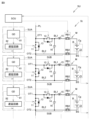
図1は、本実施の形態に係る電源システムの構成を示す図である。電源システム1は、交流電源回路2と、交流スウィープユニット3と、絶縁フィルタT1,T2と、リレーR1,R2と、分電盤C1と、GCU(Group Control Unit)100とを備える。電源システム1は、たとえば住宅、学校、病院、商業施設、または駅のような建物に対して適用される。建物内に設置された分電盤C2は、電力系統PGと電源システム1との各々から電力の供給を受けられるように構成される。分電盤C2は、屋内配線と接続され、電力系統PGと電源システム1との少なくとも一方から供給される電力を屋内配線に分配する。なお、電力系統PGの需給状況は、サーバ200によって管理される。
FIG. 1 is a diagram showing the configuration of a power supply system according to this embodiment. The
交流電源回路2は、第1直流スウィープユニット10と、第2直流スウィープユニット20と、第3直流スウィープユニット30と、第1インバータ51と、第2インバータ61と、第3インバータ71とを備える。第1直流スウィープユニット10、第2直流スウィープユニット20、第3直流スウィープユニット30は、それぞれ電池ストリングSt1、St2、St3およびSCU52、62、72を含む。また、交流スウィープユニット3は、電池ストリングSt4~St9およびSCU41~46を含む。SCUは、「String Control Unit」を意味する。本実施の形態において、SCU41~46、52、62、72および電池ストリングSt1~St9の構成は、各スウィープユニット(交流スウィープユニット3、第1直流スウィープユニット10、第2直流スウィープユニット20、第3直流スウィープユニット30)で実質的に同一であるため、これらの構成は、図2を用いて1つのスウィープユニットについてのみ説明する。
The AC
図2は、スウィープユニットSUの構成を示す図である。図2に示されるスウィープユニットSUの構成は、交流スウィープユニット3、第1直流スウィープユニット10、第2直流スウィープユニット20、および第3直流スウィープユニット30に共通の構成である。スウィープユニットSUは、SCU(図1に示したSCU41~46、52、62、72に相当)と、駆動回路SUAと、電池ストリングSt(図1に示した電池ストリングSt1~St9に相当)とを備える。電池ストリングStは、複数の電池回路モジュールMを備える。本実施の形態において、電池ストリングStに含まれる電池回路モジュールMの数は22個であるが、その数は任意であり、5~50個であってもよいし、100個以上であってもよい。本実施の形態では、各電池ストリングStが同じ数の電池回路モジュールMを含むが、電池ストリングStごとに電池回路モジュールMの数が異なっていてもよい。
FIG. 2 is a diagram showing the configuration of the sweep unit SU. The configuration of the sweep unit SU shown in FIG. 2 is common to the
各電池回路モジュールMは、電力回路SUBと、カートリッジCgとを含む。カートリッジCgは、電池Bと、監視ユニットBSとを含む。電力回路SUBと電池Bとが接続されることによって、電池Bを含む電池回路モジュールMが形成されている。駆動回路SUAは、電池回路モジュールMに含まれるスイッチ(より特定的には、後述するSW11およびSW12)を駆動するように構成される。電池Bは、ニッケル水素二次電池、あるいは、リチウムイオン二次電池であってもよい。電動車両で使用された二次電池を直列に接続することにより、電動車両で使用された二次電池を再利用して電池Bを製造してよい。 Each battery circuit module M includes a power circuit SUB and a cartridge Cg. Cartridge Cg includes a battery B and a monitoring unit BS. By connecting power circuit SUB and battery B, a battery circuit module M including battery B is formed. The drive circuit SUA is configured to drive switches included in the battery circuit module M (more specifically, SW11 and SW12, which will be described later). Battery B may be a nickel metal hydride secondary battery or a lithium ion secondary battery. Battery B may be manufactured by reusing the secondary batteries used in the electric vehicle by connecting the secondary batteries used in the electric vehicle in series.
図2に示すように、電池回路モジュールMは、電力回路SUBと、カートリッジCgと、遮断器RB1およびRB2(以下、区別しない場合は「遮断器RB」と称する)とを含む。電力回路SUBとカートリッジCgとは、遮断器RB1およびRB2を介して、互いに接続されている。SCUは、GCU100からの制御指令に従って各遮断器RBをON/OFF制御することによって、電力回路SUBとカートリッジCgとの接続状態(導通/遮断)を切り替えるように構成される。遮断器RBは、電磁式のメカニカルリレーであってもよい。遮断器RBは、ユーザが手動でON/OFFできるように構成されてもよい。
As shown in FIG. 2, the battery circuit module M includes a power circuit SUB, a cartridge Cg, and circuit breakers RB1 and RB2 (hereinafter referred to as "breaker RB" if not distinguished). Power circuit SUB and cartridge Cg are connected to each other via circuit breakers RB1 and RB2. The SCU is configured to switch the connection state (conduction/blocking) between the power circuit SUB and the cartridge Cg by controlling each circuit breaker RB to turn on/off according to a control command from the
本実施の形態では、カートリッジCgは、電力回路SUBに対して着脱可能に構成される。たとえば遮断器RB1およびRB2の各々がOFF状態(遮断状態)であるときに、ユーザはカートリッジCgを電力回路SUBから取り外してもよい。電池ストリングStは空きカートリッジがあっても動作可能であるため、ユーザは、電池ストリングStに含まれるカートリッジCgの数を増減しやすい。こうした電池ストリングStは、電池の再利用に適している。 In this embodiment, the cartridge Cg is configured to be detachable from the power circuit SUB. For example, when each of the circuit breakers RB1 and RB2 is in the OFF state (blocking state), the user may remove the cartridge Cg from the power circuit SUB. Since the battery string St can operate even if there are empty cartridges, the user can easily increase or decrease the number of cartridges Cg included in the battery string St. Such a battery string St is suitable for battery reuse.
カートリッジCgにおいて、監視ユニットBSは、電池Bの状態(たとえば、電圧、電流、および温度)を検出して、検出結果をSCUへ出力するように構成される。監視ユニットBSは、電池Bの電圧を検出する電圧センサと、電池Bの電流を検出する電流センサと、電池Bの温度を検出する温度センサとを含む。また、監視ユニットBSは、上記センサ機能に加えて、SOC(State Of Charge)推定機能、SOH(State of Health)推定機能、電池電圧の均等化機能、診断機能、および通信機能をさらに有するBMS(Battery Management System)であってもよい。SCUは、各監視ユニットBSの出力に基づいて、各電池Bの状態(たとえば、温度、電流、電圧、SOC、および内部抵抗)を取得し、得られた各電池Bの状態をGCU100へ出力する。
In the cartridge Cg, the monitoring unit BS is configured to detect the state (eg, voltage, current, and temperature) of the battery B and output the detection result to the SCU. Monitoring unit BS includes a voltage sensor that detects the voltage of battery B, a current sensor that detects the current of battery B, and a temperature sensor that detects the temperature of battery B. In addition to the above-mentioned sensor functions, the monitoring unit BS also includes a BMS ( Battery Management System). The SCU obtains the state of each battery B (for example, temperature, current, voltage, SOC, and internal resistance) based on the output of each monitoring unit BS, and outputs the obtained state of each battery B to the
電池ストリングStに含まれる電池回路モジュールMは共通の電線PLによって接続されている。電線PLは、各電池回路モジュールMの出力端子OT1およびOT2を含む。電池回路モジュールMの出力端子OT2が、当該電池回路モジュールMに隣接する電池回路モジュールMの出力端子OT1と接続されることによって、電池ストリングStに含まれる電池回路モジュールM同士が接続されている。 The battery circuit modules M included in the battery string St are connected by a common electric wire PL. Electric wire PL includes output terminals OT1 and OT2 of each battery circuit module M. By connecting the output terminal OT2 of the battery circuit module M to the output terminal OT1 of the battery circuit module M adjacent to the battery circuit module M, the battery circuit modules M included in the battery string St are connected to each other.
電力回路SUBは、第1スイッチング素子11(以下、「SW11」と称する)と、第2スイッチング素子12(以下、「SW12」と称する)と、第1ダイオード13と、第2ダイオード14と、チョークコイル15と、コンデンサ16と、出力端子OT1およびOT2とを備える。SW11およびSW12の各々は、駆動回路SUAによって駆動される。この実施の形態に係るSW11、SW12は、それぞれ本開示に係る「第1スイッチ」、「第2スイッチ」の一例に相当する。
The power circuit SUB includes a first switching element 11 (hereinafter referred to as "SW11"), a second switching element 12 (hereinafter referred to as "SW12"), a
電力回路SUBの出力端子OT1およびOT2間には、SW11と、コンデンサ16と、電池Bとが並列に接続されている。SW11は、電線PL上に位置し、出力端子OT1と出力端子OT2との接続状態(導通/遮断)を切り替えるように構成される。出力端子OT1は電線BL1を介して電池Bの正極に接続されており、出力端子OT2は電線BL2を介して電池Bの負極に接続されている。遮断器RB1、RB2は、それぞれ電線BL1、BL2に設けられている。電線BL1には、SW12およびチョークコイル15がさらに設けられている。電池回路モジュールMにおいては、電池Bと直列に接続されたSW12がON状態(導通状態)であり、かつ、電池Bと並列に接続されたSW11がOFF状態(遮断状態)であるときに、出力端子OT1およびOT2間に電池Bの電圧が印加される。
SW11,
出力端子OT1,OT2と電池Bとの間には、電線BL1および電線BL2の各々に接続されたコンデンサ16が設けられている。コンデンサ16の一端は、SW12とチョークコイル15との間で電線BL1に接続されている。コンデンサ16は、電池Bの電圧を平滑化して出力端子OT1およびOT2間に出力する。
A
SW11およびSW12の各々は、たとえばFET(電界効果トランジスタ)である。第1ダイオード13、第2ダイオード14は、それぞれSW11、SW12に対して並列に接続されている。SW12は、出力端子OT1とチョークコイル15との間に位置する。チョークコイル15は、SW12と電池Bの正極との間に位置する。電池B、チョークコイル15、およびコンデンサ16によってRCLフィルタが形成される。このRCLフィルタによって電流の平準化が図られる。なお、SW11およびSW12の各々は、FETに限られず、FET以外のスイッチであってもよい。
Each of SW11 and SW12 is, for example, a FET (field effect transistor). The
SCUは、GCU100からの制御指令に従ってゲート信号を生成する。駆動回路SUAは、電池回路モジュールMごとに設けられており、ゲート信号に従ってSW11およびSW12を駆動するGD(ゲートドライバ)81と、ゲート信号を遅延させる遅延回路82とを含む。電池回路モジュールMに含まれるSW11およびSW12の各々は、ゲート信号に従ってON/OFF制御される。
The SCU generates gate signals according to control instructions from the
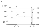
図3は、ゲート信号によって制御される電池回路モジュールMの動作の一例を示すタイムチャートである。この実施の形態では、SW11およびSW12を駆動するためのゲート信号として、矩形波信号を採用する。図3中に示されるゲート信号の「Low」、「High」は、それぞれゲート信号(矩形波信号)のLレベル、Hレベルを意味する。また、「出力電圧」は、出力端子OT1およびOT2間に出力される電圧を意味する。 FIG. 3 is a time chart showing an example of the operation of the battery circuit module M controlled by the gate signal. In this embodiment, a rectangular wave signal is used as the gate signal for driving SW11 and SW12. "Low" and "High" of the gate signal shown in FIG. 3 mean the L level and H level of the gate signal (rectangular wave signal), respectively. Moreover, "output voltage" means the voltage output between output terminals OT1 and OT2.
電池回路モジュールMの初期状態では、駆動回路SUAにゲート信号が入力されず(ゲート信号=Lレベル)、SW11、SW12がそれぞれON状態、OFF状態になっている。 In the initial state of the battery circuit module M, no gate signal is input to the drive circuit SUA (gate signal=L level), and SW11 and SW12 are in the ON state and OFF state, respectively.
駆動回路SUAにゲート信号が入力されると、GD81が、入力されたゲート信号に従ってSW11およびSW12を駆動する。図3に示す例では、タイミングt1で、ゲート信号がLレベルからHレベルに立ち上がり、ゲート信号の立ち上がりと同時にSW11がON状態からOFF状態に切り替わる。そして、ゲート信号の立ち上がりから所定の時間(以下、「dt1」と表記する)だけ遅れたタイミングt2で、SW12がOFF状態からON状態に切り替わる。これにより、電池回路モジュールMが駆動状態になる。以下、ゲート信号の立ち上がりからdt1が経過するまでの期間を、「第1遅延期間」とも称する。 When a gate signal is input to the drive circuit SUA, GD81 drives SW11 and SW12 according to the input gate signal. In the example shown in FIG. 3, at timing t1, the gate signal rises from the L level to the H level, and at the same time as the gate signal rises, the SW11 switches from the ON state to the OFF state. Then, at timing t2, which is delayed by a predetermined time (hereinafter referred to as "dt1") from the rise of the gate signal, the SW12 is switched from the OFF state to the ON state. As a result, the battery circuit module M enters the driving state. Hereinafter, the period from the rise of the gate signal to the elapse of dt1 will also be referred to as a "first delay period."
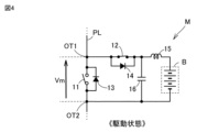
図4は、駆動状態の電池回路モジュールMを示す図である。図4を参照して、駆動状態の電池回路モジュールMでは、SW11がOFF状態かつSW12がON状態になることで、出力端子OT1およびOT2間に電池Bの電圧が印加される。電池Bの電圧がコンデンサ16を介して出力端子OT1およびOT2間に印加されることで、電圧Vmが出力端子OT1およびOT2間に出力される。
FIG. 4 is a diagram showing the battery circuit module M in a driving state. Referring to FIG. 4, in battery circuit module M in the driving state, SW11 is in the OFF state and SW12 is in the ON state, so that the voltage of battery B is applied between output terminals OT1 and OT2. By applying the voltage of battery B between output terminals OT1 and OT2 via
再び図3を参照して、タイミングt3で、ゲート信号がHレベルからLレベルに立ち下がると、ゲート信号の立ち下がりと同時にSW12がON状態からOFF状態に切り替わる。これにより、電池回路モジュールMが停止状態になる。停止状態の電池回路モジュールMでは、SW12がOFF状態になることで、出力端子OT1およびOT2間に電池Bの電圧が印加されなくなる。その後、ゲート信号の立ち下がりから所定の時間(以下、「dt2」と表記する)だけ遅れたタイミングt4で、SW11がOFF状態からON状態に切り替わる。dt1とdt2とは互いに同じであっても異なってもよい。この実施の形態では、dt1およびdt2の各々を100n秒とする。ただし、dt1およびdt2の各々は任意に設定できる。 Referring again to FIG. 3, at timing t3, when the gate signal falls from the H level to the L level, SW12 switches from the ON state to the OFF state simultaneously with the fall of the gate signal. This causes the battery circuit module M to be in a stopped state. In the battery circuit module M in the stopped state, the voltage of the battery B is no longer applied between the output terminals OT1 and OT2 because SW12 is turned off. Thereafter, at timing t4, which is delayed by a predetermined time (hereinafter referred to as "dt2") from the fall of the gate signal, the SW11 is switched from the OFF state to the ON state. dt1 and dt2 may be the same or different. In this embodiment, each of dt1 and dt2 is 100 ns. However, each of dt1 and dt2 can be set arbitrarily.
以下、ゲート信号の立ち下がりからdt2が経過するまでの期間を、「第2遅延期間」とも称する。また、第2遅延期間終了から電池回路モジュールMが駆動状態になるまでの期間を、「停止期間」とも称する。 Hereinafter, the period from the fall of the gate signal until dt2 has elapsed will also be referred to as a "second delay period." Further, the period from the end of the second delay period until the battery circuit module M enters the driving state is also referred to as a "stop period."
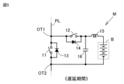
図5は、遅延期間における電池回路モジュールMの状態を示す図である。図5に示すように、第1遅延期間および第2遅延期間の各々では、SW11およびSW12の両方がOFF状態になる。 FIG. 5 is a diagram showing the state of the battery circuit module M during the delay period. As shown in FIG. 5, both SW11 and SW12 are in the OFF state in each of the first delay period and the second delay period.
図6は、停止期間における電池回路モジュールMの状態を示す図である。図6に示すように、停止期間では、初期状態と同様、SW11がON状態かつSW12がOFF状態になる。 FIG. 6 is a diagram showing the state of the battery circuit module M during the stop period. As shown in FIG. 6, during the stop period, SW11 is in the ON state and SW12 is in the OFF state, similar to the initial state.
上記遅延期間および停止期間のいずれの期間においても、電池回路モジュールMは停止状態になっている。停止状態の電池回路モジュールMでは、出力端子OT1およびOT2間に電圧が印加されない。第1遅延期間および第2遅延期間が設けられていることで、SW11およびSW12が同時にON状態になること(すなわち、電池回路モジュールMが短絡状態になること)が抑制される。 During both the delay period and the stop period, the battery circuit module M is in a stopped state. In the battery circuit module M in the stopped state, no voltage is applied between the output terminals OT1 and OT2. By providing the first delay period and the second delay period, SW11 and SW12 are prevented from being in the ON state at the same time (that is, the battery circuit module M is prevented from being in a short-circuited state).
電池ストリングStに含まれる電池回路モジュールMを、上述のように制御することにより、駆動状態の電池回路モジュールMの数を調整することができ、電池ストリングStの出力電圧を制御することができる。同時に駆動状態になる電池回路モジュールMの数を調整することにより、スウィープユニットSUは、0Vから、電池ストリングStに含まれる各電池Bの電圧の総和までの電圧を出力可能に構成される。 By controlling the battery circuit modules M included in the battery string St as described above, the number of battery circuit modules M in the driving state can be adjusted, and the output voltage of the battery string St can be controlled. By adjusting the number of battery circuit modules M that are simultaneously activated, the sweep unit SU is configured to be able to output a voltage from 0V to the sum of the voltages of the batteries B included in the battery string St.
再び図1を参照して、第1直流スウィープユニット10は、上述したスウィープユニットSUの構成を有する。すなわち、第1直流スウィープユニット10は、電池ストリングSt1とSCU52とを含む。電池ストリングSt1に含まれる電池回路モジュールMの電池Bは、ニッケル水素二次電池である。第1直流スウィープユニット10から出力された直流電力は、第1インバータ51に入力される。図7は、第1インバータ51の構成を示す図である。図1とともに図7を参照して、第1インバータ51は、三相インバータであり、U相アームに互いに直列に接続されたスイッチング素子q1、q2と、V相アームに互いに直列に接続されたスイッチング素子q3、q4と、W相アームに互いに直列に接続されたスイッチング素子q5、q6とを備える。スイッチング素子q1~q6のコレクタ-エミッタ間には、ダイオードd1~d6が逆並列にそれぞれ接続されている。
Referring to FIG. 1 again, the first
第1インバータ51の各相アームの中間点は、絶縁フィルタT1に接続されており、さらに、リレーR1および分電盤C1を介して、電力系統PGに接続されている(図1参照)。第1インバータ51の各スイッチング素子q1~q6は、GCU100からの制御指令によって、たとえば、PWM(Pulse Width Modulation)制御によりON/OFFされる。第1インバータ51は、第1直流スウィープユニット10から出力される直流電力を交流電力(三相交流電力)に変換して電力系統PGへ供給する。また、第1インバータ51は、電力系統PGから供給される交流電力(三相交流電力)を、直流電力に変換して第1直流スウィープユニット10に供給し、電池ストリングSt1の電池Bを充電する。本実施の形態において、第1インバータ51は、電動車両の三相同期電動機を駆動するために使用された三相インバータを再利用している。
The intermediate point of each phase arm of the
図1において、電池ストリングSt2とSCU62とを含む第2直流スウィープユニット20、および、電池ストリングSt3とSCU72とを含む第3直流スウィープユニット30の各々は、第1直流スウィープユニット10と同じ構成を有する。第2直流スウィープユニット20に接続された第2インバータ61、および、第3直流スウィープユニット30に接続された第3インバータ71の各々は、図7に示した第1インバータ51と同じ構成を有する。第1直流スウィープユニット10、第2直流スウィープユニット20、および第3直流スウィープユニット30は、図1に示すように、絶縁フィルタT1に対して並列に接続されている。第1インバータ51、第2インバータ61、および第3インバータ71の各相アームの中間点(図7参照)が電力線で接続されている。そして、交流電源回路2は、並列に接続された第1直流スウィープユニット10、第2直流スウィープユニット20、および第3直流スウィープユニット30から第1~第3インバータ51,61,71を介して交流電力(三相交流電力)を絶縁フィルタT1へ出力する。
In FIG. 1, each of the second
図8は、交流スウィープユニット3の構成を示す図である。図8を参照して、電池ストリングSt4、St5、St6、St7、St8、St9は、それぞれ第1のU相用電池ストリング、第2のU相用電池ストリング、第1のV相用電池ストリング、第2のV相用電池ストリング、第1のW相用電池ストリング、第2のW相用電池ストリングに相当する。電池ストリングSt4~St9の各々は、図2に示した電池ストリングStと実質的に同一の構成を有し、SCU41~46の各々は、図2に示したSCUと実質的に同一の構成を有する。
FIG. 8 is a diagram showing the configuration of the
本実施の形態において、電池ストリングSt4、St6、およびSt8の各々に含まれる電池回路モジュールMの電池Bは、三元系(NMC)のリチウムイオン二次電池である。また、電池ストリングSt5、St7、およびSt9の各々に含まれる電池回路モジュールMの電池Bは、リン酸鉄系(LFP)のリチウムイオン二次電池である。 In this embodiment, battery B of battery circuit module M included in each of battery strings St4, St6, and St8 is a ternary (NMC) lithium ion secondary battery. Further, the battery B of the battery circuit module M included in each of the battery strings St5, St7, and St9 is an iron phosphate-based (LFP) lithium ion secondary battery.
図8において、電池ストリングSt4の正極端子と電池ストリングSt5の正極端子とは、電力線PLuに接続されている。電池ストリングSt6の正極端子と電池ストリングSt7の正極端子とは、電力線PLvに接続されている。電池ストリングSt8の正極端子と電池ストリングSt9の正極端子とは、電力線PLwに接続されている。また、各電池ストリングSt4~St9の負極端子は、中性点N1に接続されている。交流スウィープユニット3は、並列に接続された電池ストリングSt4およびSt5と、並列に接続された電池ストリングSt6およびSt7と、並列に接続された電池ストリングSt8およびSt9とが、Y結線された構成を有する。
In FIG. 8, the positive terminal of battery string St4 and the positive terminal of battery string St5 are connected to power line PLu. The positive terminal of battery string St6 and the positive terminal of battery string St7 are connected to power line PLv. The positive terminal of battery string St8 and the positive terminal of battery string St9 are connected to power line PLw. Further, the negative terminal of each battery string St4 to St9 is connected to the neutral point N1. The
SCU41~46は、GCU100からの制御指令により、各電池回路モジュールMのSW11およびSW12を数十kHzのスイッチング周波数で制御して、各電池ストリングSt4~St9のストリング電圧(出力電圧)を、図8の下方に示した電圧波形になるように制御する。図8において、線L11は、U相用電池ストリング(電池ストリングSt4,St5)のストリング電圧である。線L12は、V相用電池ストリング(電池ストリングSt6,St7)のストリング電圧である。線L13は、W相用電池ストリング(電池ストリングSt8,St9)のストリング電圧である。線L11、線L12、および線L13は、位相が120°ずれた正弦波であり、その周波数は、電力系統PGに対応した60Hzである。
Based on the control command from the
このように、電池ストリングSt4~St9の各々のストリング電圧が制御されることにより、電力線PLu、PLv、およびPLwの線間電圧は、図8の上方に示した電圧波形になる。図8において、線L21は電力線PLuと電力線PLvの線間電圧「Vuv」を示し、線L22は電力線PLwと電力線PLuの線間電圧「Vwu」を示し、線L23は電力線PLvと電力線PLwの線間電圧「Vvw」を示している。各線間電圧は、周期的に極性(正/負)が変わる正弦波交流波形になる。これにより、交流スウィープユニット3から、交流電力(三相交流電力)が出力される。
By controlling the string voltage of each of the battery strings St4 to St9 in this way, the line voltages of the power lines PLu, PLv, and PLw have the voltage waveform shown in the upper part of FIG. 8. In FIG. 8, a line L21 indicates the line voltage "Vuv" between the power line PLu and the power line PLv, a line L22 indicates the line voltage "Vwu" between the power line PLw and the power line PLu, and a line L23 indicates the line voltage between the power line PLv and the power line PLw. It shows the voltage between ``Vvw''. Each line voltage has a sinusoidal AC waveform whose polarity (positive/negative) changes periodically. As a result, AC power (three-phase AC power) is output from the
再び図1を参照して、交流電源回路2から出力された交流電力は、絶縁フィルタT1、リレーR1、および分電盤C1を介して、電力系統PGに供給される。交流スウィープユニット3から出力された交流電力は、絶縁フィルタT2、リレーR2、および分電盤C1を介して、電力系統PGに供給される。このように、電源システム1は、電力系統PGに対して、交流電源回路2および交流スウィープユニット3から三相交流電力を逆潮流する系統連携運転が可能とされている。
Referring again to FIG. 1, AC power output from AC
絶縁フィルタT1およびT2の各々は、たとえば、LCLフィルタと三相トランスとを含む。絶縁フィルタT1およびT2の各々は、LCLフィルタによって三相交流成分のノイズ成分を低減し、三相トランスによって三相交流電力を所定の電圧(たとえば、200V)に変換するとともに入力側と出力側との絶縁を行なう。 Each of the isolation filters T1 and T2 includes, for example, an LCL filter and a three-phase transformer. Each of the insulating filters T1 and T2 reduces the noise component of the three-phase AC component with an LCL filter, converts the three-phase AC power into a predetermined voltage (for example, 200V) with a three-phase transformer, and connects the input side and output side. Perform insulation.
リレーR1およびR2の各々は、たとえば電磁式のメカニカルリレーであり、GCU100によってリレーR1のON/OFFを制御することにより、交流電源回路2と電力系統PGとの接続(並列)/遮断(解列)を行なう。また、GCU100によってリレーR2のON/OFFを制御することにより、交流スウィープユニット3と電力系統PGとの接続(並列)/遮断(解列)を行なう。
Each of the relays R1 and R2 is, for example, an electromagnetic mechanical relay, and by controlling ON/OFF of the relay R1 by the
分電盤C1は、漏電遮断器および/またはブレーカを備え、交流電源回路2と交流スウィープユニット3とに含まれる電池ストリングStの電池Bを充電する際に、電力系統PGの電力を交流電源回路2と交流スウィープユニット3とに分配する。また、分電盤C1は、交流電源回路2と交流スウィープユニット3とから出力された電力を、電力系統PGおよび/または分電盤C2へ供給する。
The distribution board C1 is equipped with an earth leakage circuit breaker and/or a breaker, and when charging the battery B of the battery string St included in the AC
なお、交流電源回路2に含まれる電池ストリングStの電池Bを充電する際には、電力系統PGから供給される交流電力を第1~第3インバータ51,61,71が直流電力に変換することで電池Bを充電する。交流スウィープユニット3に含まれる電池ストリングStの電池Bを充電する際には、電力系統PGから供給される交流電圧に対して電池ストリングStの電圧が少し低くなるようにSCU41~46がSW11およびSW12を制御することで電池Bを充電する。
Note that when charging the battery B of the battery string St included in the AC
交流電源回路2が出力する交流電力と、交流スウィープユニット3が出力する交流電力とは、電力系統PGが出力する交流電力とともに、分電盤C2を介して、構内または宅内の配線に供給される。
The AC power output by the AC
サーバ200は、電力会社(発電事業者および送配電事業者)によって提供される電力系統PG(電力網)の需給を管理する。サーバ200は、GCU100と通信可能に構成され、必要に応じて、GCU100に電力系統PGの電力調整を要求する。GCU100は、サーバ200からの要求を受け、各SCUと、第1~第3インバータ51,61,71と、リレーR1、R2とを制御し、交流電源回路2および交流スウィープユニット3の入出力電力を調整する。
The
サーバ200から要求される電力調整は、下げDR(デマンドレスポンス)と上げDRに大別される。下げDRは、電力の需要を減らす要請である。本実施の形態では、下げDRの要請に際し、電池ストリングStの電池回路モジュールMに含まれる電池Bから放電を行なうことにより、電源システム1から三相交流電力を出力し、電力系統PGに対して逆潮流を行なう。電力調整として交流電力の出力が要求されたとき、電源システム1から交流電力を出力する。上げDRは、電力の需要を増加する要請である。本実施の形態では、上げDRの要請に際し、電源システム1は、電池ストリングStの電池回路モジュールMに含まれる電池Bを充電することにより、要請に応える。電力調整として電力系統PGの電力消費が要求されたとき、電池Bの充電を行なう。
The power adjustment requested by the
図9は、サーバ200から電力の調整要求がなされた際、GCU100が実行する処理の一例を示すフローチャートである。このフローチャートは、GCU100がサーバ200から調整要求を受信すると実行される。サーバ200から調整要求を受信すると、ステップ(以下、ステップを「S」と略す)10において、調整要求が、下げDRの要請か否かを判定する。調整要求が下げDRである場合、肯定判定されS11へ進み、調整要求が上げDRの場合、否定判定されS16へ進む。
FIG. 9 is a flowchart illustrating an example of a process executed by the
S11では、GCU100が、下げDRの要請に応じて、交流電源回路2および交流スウィープユニット3から交流電力を出力し、電力系統PGへ供給する。GCU100は、リレーR1をONとして、交流電源回路2と電力系統PGを接続(並列)する。GCU100は、SCU52,62,72によって電池ストリングSt1~St3のSW11およびSW12を制御することにより、第1直流スウィープユニット10、第2直流スウィープユニット20および第3直流スウィープユニット30から直流電力を出力させる。GCU100は、その直流電力を第1~第3インバータ51,61,71を用いて交流電力に変換させ、その交流電力(三相交流電力)を電力系統PGに供給する。また、GCU100は、リレーR2をONとして、交流スウィープユニット3と電力系統PGを接続(並列)するとともに、SCU41~46によって電池ストリングSt4~St9のSW11およびSW12を制御し、交流スウィープユニット3から交流電力(三相交流電力)を出力する。
In S11, the
続くS12では、交流電源回路2および交流スウィープユニット3から交流電力の出力を開始してから、第1所定期間が経過したか否かを判定する。第1所定期間は、たとえば5秒であってよい。第1所定期間が経過していない場合、否定判定されS11に戻り、交流電源回路2および交流スウィープユニット3から、交流電力の出力を継続する。第1経過時間が経過すると、肯定判定されS13へ進む。
In subsequent S12, it is determined whether a first predetermined period has elapsed since the AC
S13では、交流電源回路2からの交流電力の出力を停止し、交流スウィープユニット3から交流電力を出力する。また、リレーR1をOFFとして、交流電源回路2と電力系統PGとを遮断(解列)する。GCU100は、第1~第3インバータ51,61,71の駆動を停止し、SCU52,62,72によって電池ストリングSt1~St3のSW11をON状態、SW12をON状態として、電池回路モジュールMを停止状態(図6参照)とする。
In S13, the output of AC power from the AC
続くS14では、下げDRの期間が終了したか否かを判定する。たとえば、サーバ200から要求された下げDRの調整時間が完了したとき、下げDRの期間が終了したと判定してよい。下げDRの期間が終了していない場合、否定判定されS13へ戻り、交流スウィープユニット3から、交流電力の出力を継続する。下げDRの期間が終了すると、肯定判定されS15へ進む。
In subsequent S14, it is determined whether the period of lower DR has ended. For example, when the adjustment time for lower DR requested by the
S15では、交流スウィープユニット3からの交流電力の出力も停止する。GCU100は、リレーR2をOFFとして、交流スウィープユニット3と電力系統PGを遮断(解列)するとともに、SCU41~46によって電池ストリングSt4~St9のSW11をON状態、SW12をON状態として、電池回路モジュールMを停止状態(図6参照)とすることにより、交流スウィープユニット3からの出力を停止し、今回のルーチンを終了する。
In S15, the output of AC power from the
S16では、GCU100が、上げDRの要請に応じて、交流電源回路2および交流スウィープユニット3に含まれる電池Bの充電を行なう。GCU100は、リレーR1をONとして、交流電源回路2と電力系統PGとを接続(並列)する。GCU100は、第1~第3インバータ51,61,71を用いて電力系統PGの交流電力を直流電力に変換する。GCU100は、SCU52,62,72によって電池ストリングSt1~St3のSW11およびSW12を制御することにより、第1直流スウィープユニット10、第2直流スウィープユニット20および第3直流スウィープユニット30に含まれる電池Bを充電する。GCU100は、リレーR2をONとして、交流スウィープユニット3と電力系統PGとを接続(並列)する。GCU100は、電力系統PGから供給される交流電圧に対して各電池ストリングStの電圧が低くなるようにSCU41~46によりSW11およびSW12を制御し、交流スウィープユニット3に含まれる各電池ストリングStの電池Bの充電を行なう。
In S16, the
続くS17では、交流電源回路2および交流スウィープユニット3が充電を開始してから、第2所定期間が経過したか否かを判定する。第2所定期間は、たとえば5秒であってよい。第2所定期間が経過していない場合、否定判定されS16に戻り、交流電源回路2および交流スウィープユニット3に含まれる電池Bの充電を継続する。第2経過時間が経過すると、肯定判定されS18へ進む。
In subsequent S17, it is determined whether a second predetermined period has elapsed since the AC
S18では、電池BのSOCに応じて、電池Bの充電を行なう。GCU100は、交流電源回路2および交流スウィープユニット3における、電池ストリングStの電池回路モジュールMの監視ユニットBSから各電池BのSOCを取得している。GCU100は、各電池BのSOCに基づいて、電池ストリングStに含まれる各電池BのSOCが均一になるよう、SCUによって、SW11およびSW12を制御する。たとえば、第1直流スウィープユニット10の電池ストリングSt1に含まれる各電池BのSOCが均一になるよう、SCU52によってSW11およびSW12を制御する。同様に、他のスウィープユニット(交流スウィープユニット3、第2直流スウィープユニット20、第3直流スウィープユニット30)においても、そのスウィープユニットの電池ストリングStに含まれる各電池BのSOCが均一になるよう、SCUによってSW11およびSW12を制御する。これにより、各電池ストリングStのSOCが調整される。
In S18, battery B is charged according to the SOC of battery B. The
S18において、各電池ストリングStのSOCが同じ値になるよう、電池B(電池ストリングSt)の充電を制御してもよい。また、交流スウィープユニット3に含まれる電池ストリングSt4~St9のSOCが、交流電源回路2に含まれる電池ストリングSt1~St3のSOCよりも大きくなるよう、電池B(電池ストリングSt)の充電を制御してもよい。この場合、たとえば、電池ストリングSt1~St3のSOCが80%を超えたとき、GCU100は、リレーR1をOFFとして、交流電源回路2と電力系統PGを遮断(解列)し、第1~第3インバータ51,61,71の駆動を停止し、SCU52,62,72によって電池ストリングSt1~St3のSW11をON状態、SW12をON状態として、電池回路モジュールMを停止状態として、充電を停止する。
In S18, charging of battery B (battery string St) may be controlled so that the SOC of each battery string St becomes the same value. Furthermore, charging of battery B (battery string St) is controlled so that the SOC of battery strings St4 to St9 included in
続くS19では、上げDRの期間が終了したか否かを判定する。たとえば、サーバ200から要求された上げDRの調整時間が完了したとき、上げDRの期間が終了したと判定してよい。上げDRの期間が終了していない場合、否定判定されS18へ戻り、電池Bの充電を継続する。上げDRの期間が終了すると、肯定判定されS15へ進む。
In the following S19, it is determined whether the period of up DR has ended. For example, when the adjustment time for raised DR requested by the
S15では、電池Bの充電を停止する。GCU100は、リレーR2をOFFとして、交流スウィープユニット3と電力系統PGとを遮断(解列)するとともに、SCU41~46によって電池ストリングSt4~St9のSW11をON状態、SW12をON状態として、電池回路モジュールMを停止状態とすることにより、交流スウィープユニット3の電池Bの充電を停止する。また、交流電源回路2の電池Bの充電を行なっている場合は、上記の通り、GCU100は、リレーR1をOFFとして、交流電源回路2と電力系統PGとを遮断(解列)し、第1~第3インバータ51,61,71の駆動を停止する。その後、GCU100は、SCU52,62,72によって電池ストリングSt1~St3のSW11をON状態、SW12をON状態として、電池回路モジュールMを停止状態とする。そして、GCU100は、充電を停止した後、今回のルーチンを終了する。
In S15, charging of battery B is stopped. The
交流電源回路2に含まれる、第1直流スウィープユニット10、第2直流スウィープユニット20および第3直流スウィープユニット30の電池ストリングSt1~St3に含まれる各電池Bは、ニッケル水素二次電池である。交流スウィープユニット3の電池ストリングSt4~St9に含まれる各電池Bは、リチウムイオン二次電池である。これらのスウィープユニットにおいて使用されるリチウムイオン二次電池およびニッケル水素二次電池に関して、リチウムイオン二次電池のエネルギー密度(Wh/kg)は、ニッケル水素二次電池のエネルギー密度より大きい。すなわち、この実施の形態に係るニッケル水素二次電池は、ラゴンプロットにおいて、左上の領域に位置し、パワー型(出力型)電池であるといえる。また、この実施の形態に係るリチウムイオン二次電池は、ラゴンプロットにおいて、右下の領域に位置し、エネルギー型(容量型)電池であるといえる。
Each battery B included in the battery strings St1 to St3 of the first
交流スウィープユニット3では、各電池ストリングStのSW11およびSW12を数十kHzで制御して交流電力を出力しているので、効率が低く、最大出力(最大電力)を抑えることが望ましい。このため、交流スウィープユニット3の出力(kW)を大きくするには、電池ストリングStの並列数を多くする必要があり、コストの増大を招く。交流スウィープユニット3は最大出力(最大電力)を抑えることが望ましいので、交流スウィープユニット3の各電池Bは低レート(小さな電流)で充放電するよう使用することが好ましい。したがって、交流スウィープユニット3の各電池ストリングStの電池Bは、エネルギー密度が大きい、エネルギー型電池が望ましい。そこで、本実施の形態では、上述のリチウムイオン二次電池を用いている。
In the
これに対して、交流電源回路2では、インバータを用いて交流電力を出力しているので、比較的効率が高く、最大出力を大きくすることが可能である。したがって、交流電源回路2の各電池B(すなわち、第1直流スウィープユニット10、第2直流スウィープユニット20および第3直流スウィープユニット30の電池ストリングSt1~St3に含まれる各電池B)として、出力密度が大きいパワー型電池を用いることにより、交流電源回路2から大きな出力(kW)を出力することができる。そこで、本実施の形態では、上述のニッケル水素二次電池を用いている。
On the other hand, since the AC
図9の例によれば、サーバ200から電力の調整要求がなされた際、調整要求が下げDRの要請であり、電力調整として交流電力の出力が要求されたとき(S10で肯定判定)、交流スウィープユニット3および交流電源回路2から交流電力を出力する(S11)。交流電力の出力要求があったとき、交流スウィープユニット3の出力に加え、出力密度の高い電池を含む交流電源回路2(第1直流スウィープユニット10、第2直流スウィープユニット20および第3直流スウィープユニット30の電池ストリングSt1~St3)から高出力の電力を出力するので、早期に電流を安定させることができる。そして、第1所定期間経過後(S12で肯定判定)、交流電源回路2からの交流電力の出力を停止して、交流スウィープユニット3から交流電力を出力する(S13)。第1所定期間経過後には、電流が安定するので、交流スウィープユニット3のみから電力を出力することにより、電力調整に応えることができる。特に、本実施の形態では、交流スウィープユニット3の電池ストリングStの電池Bは、エネルギー密度が大きく、長時間にわたって、効率良く、安定して交流電力を出力することが可能になる。
According to the example in FIG. 9, when a power adjustment request is made from the
図9の例によれば、サーバ200から電力の調整要求がなされた際、調整要求が上げDRの要請であり、電力調整として電力系統PG(外部電源)の電力消費が要求されたとき(S10で否定判定)、交流スウィープユニット3および交流電源回路2に含まれる電池Bの充電を行なう(S16)。電力系統PGの電力の消費要求があったとき、交流スウィープユニット3に含まれる電池Bに加え、出力密度の高い電池を含む交流電源回路2の電池B(第1直流スウィープユニット10、第2直流スウィープユニット20および第3直流スウィープユニット30に含まれる電池B)へ充電が行われる。出力密度の高い電池Bは入力密度も高いので、早期に電流(充電電流)を安定することができる。そして、第2所定期間経過後には、電流が安定するので、電池BのSOCに応じて充電を行なうことにより、安定した充電を行なうことができる。
According to the example in FIG. 9, when a power adjustment request is made from the
上記実施の形態において、第1所定期間を、交流電源回路2に含まれる電池B(電池ストリングSt1~St3)の状態に応じて、設定するようにしてもよい。図10は、第1所定期間を設定するマップの例を示した図である。図10(A)は、交流電源回路2の電池Bの温度に基づいて、第1所定期間を設定するマップである。横軸は電池Bの温度であり、縦軸は第1所定期間の時間を示している。電池Bの温度は、監視ユニットBSで検出した電池温度であってよい。横軸の電池Bの温度は、たとえば、電池ストリングSt1~St3に含まれる電池Bの温度の最大値であってよい。また、電池ストリングStに含まれる電池Bの平均温度を電池ストリングStの温度として、電池ストリングSt1~St3のうち、最も温度の高い電池ストリングStの温度を、図10(A)の横軸の電池Bの温度としてもよい。
In the embodiment described above, the first predetermined period may be set depending on the state of the battery B (battery strings St1 to St3) included in the AC
交流電源回路2に含まれる電池B(電池ストリングSt1~St3の電池B)の温度が高いとき、たとえば、図10(A)に示した温度Tcより電池Bの温度が高い状態で電池Bから放電を行なうと、電池Bの劣化が促進される可能性がある。したがって、図10(A)に示すように、電池Bの温度が温度Tcよりも高いとき、第1所定期間を短く設定することにより、電池Bの放電時間(交流電源回路2からの交流電力の出力時間)を短くして、電池Bの劣化を抑制することができる。
When the temperature of battery B (battery B of battery strings St1 to St3) included in AC
図10(B)は、交流電源回路2の電池BのSOCに基づいて、第1所定期間を設定するマップである。横軸は電池BのSOCであり、縦軸は第1所定期間の時間を示している。電池BのSOCは、監視ユニットBSで推定したSOCであってもよい。本実施の形態では、上述のように、電池Bの充電時に、電池ストリングStに含まれる電池BのSOCが均一になるよう、SCUによって、SW11およびSW12を制御している。したがって、横軸の電池BのSOCは、電池ストリングSt1~St3のSOCであると見做すことができる。電池ストリングSt1~St3に含まれる電池BのSOCが小さい場合、交流電源回路2から交流電力を出力すると、電池BのSOCがさらに小さくなり、許容される下限値より小さくなって、電池Bの劣化が促進する可能性がある。したがって、図10(B)に示すように、電池BのSOCが小さいほど、第1所定期間が短くなるよう設定し、電池Bの放電時間(交流電源回路2からの交流電力の出力時間)を短くして、電池Bの劣化を抑制する。
FIG. 10(B) is a map for setting the first predetermined period based on the SOC of battery B of AC
第1所定期間は、図10(A)あるいは(B)のいずれかのマップを用いて設定してもよく、図10(A)および(B)の両方のマップを用いて設定してもよい。両方のマップを用いて設定する場合は、図10(A)のマップを用いて設定した第1所定期間と、図10(B)のマップを用いて設定した第1所定期間のうち、短い方を、第1所定期間として設定する。 The first predetermined period may be set using either the map in FIG. 10(A) or (B), or may be set using both the maps in FIG. 10(A) and (B). . When setting using both maps, the shorter of the first predetermined period set using the map in FIG. 10(A) and the first predetermined period set using the map in FIG. 10(B). is set as the first predetermined period.
本実施の形態によれば、第1~第3直流スウィープユニット10~30の出力を第1~第3インバータ51,61,71を用いて交流電力に変換し、交流電力を出力する交流電源回路2の電池ストリングStの電池として、出力密度の高いニッケル水素二次電池を使用している。また、Y結線されたU相用電池ストリング(電池ストリングSt4およびSt5)とV相用電池ストリング(電池ストリングSt6およびSt7)とW相用電池ストリング(電池ストリングSt8およびSt9)とから交流電力を出力する交流スウィープユニット3の電池Bとして、エネルギー密度の高いリチウムイオン二次電池を使用している。したがって、本実施の形態の電源システム1では、パワー型電池(ニッケル水素二次電池)とエネルギー型電池(リチウムイオン二次電池)とを組み合わせることで、各電池に得意な出力(高出力/長期出力)を行わせることが可能になる。これにより、エネルギー型電池単独あるいはパワー型電池単独の電源システムよりも、安価に高出力かつ高容量の電源システム1を提供することができる。
According to this embodiment, the AC power supply circuit converts the outputs of the first to third
本実施の形態では、交流スウィープユニット3は、電池ストリングStをY結線することで、交流(三相交流)を出力している。インバータを用いていないので、コストを削減することができる。
In this embodiment, the
本実施の形態では、交流電源回路2では、第1直流スウィープユニット10、第2直流スウィープユニット20、および第3直流スウィープユニット30が並列に接続されている。第1~第3直流スウィープユニット10~30は、本開示の「直流スウィープユニット」に相当し、電池ストリングSt1~St3は、本開示の「直流用電池ストリング」に相当する。本実施の形態では、直流スウィープユニットを3個並列に接続していたが、直流スウィープユニットの数は、1個であってもよく、4個以上であってもよい。
In this embodiment, in the AC
本実施の形態では、交流スウィープユニット3において、U相用電池ストリングとして電池ストリングSt4およびSt5を使用し、V相用電池ストリングとして電池ストリングSt6およびSt7を使用し、W相用電池ストリングとして電池ストリングSt8およびSt9を使用している。U相用電池ストリング、V相用電池ストリング、およびW相用電池ストリングの数は、1個であってもよく、3個以上であってもよい。
In this embodiment, in the
本実施の形態では、電池ストリングSt4、St6、およびSt8の電池Bに、三元系(NMC)のリチウムイオン二次電池を使用し、電池ストリングSt5、St7、およびSt9の電池Bに、リン酸鉄系(LFP)のリチウムイオン二次電池を使用していたが、各電池ストリングStのリチウムイオン二次電池の種類は任意であり、各タイプのリチウムイオン二次電池が混在していてもよい。 In this embodiment, a ternary (NMC) lithium ion secondary battery is used for battery B of battery strings St4, St6, and St8, and a phosphoric acid secondary battery is used for battery B of battery strings St5, St7, and St9. Although iron-based (LFP) lithium ion secondary batteries were used, the type of lithium ion secondary batteries in each battery string St is arbitrary, and each type of lithium ion secondary batteries may be mixed. .
今回開示された実施の形態は、すべての点で例示であって制限的なものではないと考えられるべきである。本発明の範囲は、上記した実施の形態の説明ではなくて特許請求の範囲によって示され、特許請求の範囲と均等の意味および範囲内でのすべての変更が含まれることが意図される。 The embodiments disclosed this time should be considered to be illustrative in all respects and not restrictive. The scope of the present invention is indicated by the claims rather than the description of the embodiments described above, and it is intended that all changes within the meaning and range equivalent to the claims are included.
1 電源システム、2 交流電源回路、3 交流スウィープユニット、10 第1直流スウィープユニット、11 第1スイッチング素子、12 第2スイッチング素子、13 第1ダイオード、14 第2ダイオード、15 チョークコイル、16 コンデンサ、20 第2直流スウィープユニット、30 第3直流スウィープユニット、41~46,52,62,72 SCU、51 第1インバータ、61 第2インバータ、71 第3インバータ、81 ゲートドライバ、82 遅延回路、100 GCU、200 サーバ、B 電池、BS 監視ユニット、Cg カートリッジ、C1,C2 分電盤、M 電池回路モジュール、OT1,OT2 出力端子、PG 電力系統、R1,R2 リレー、RB1,RB2 遮断器、SUA 駆動回路、SUB 電力回路、St,St1~St9 電池ストリング、SU スウィープユニット、 T1,T2 絶縁フィルタ。 1 power supply system, 2 AC power supply circuit, 3 AC sweep unit, 10 first DC sweep unit, 11 first switching element, 12 second switching element, 13 first diode, 14 second diode, 15 choke coil, 16 capacitor, 20 second DC sweep unit, 30 third DC sweep unit, 41 to 46, 52, 62, 72 SCU, 51 first inverter, 61 second inverter, 71 third inverter, 81 gate driver, 82 delay circuit, 100 GCU , 200 server, B battery, BS monitoring unit, Cg cartridge, C1, C2 distribution board, M battery circuit module, OT1, OT2 output terminal, PG power system, R1, R2 relay, RB1, RB2 circuit breaker, SUA drive circuit , SUB power circuit, St, St1 to St9 battery string, SU sweep unit, T1, T2 insulation filter.
Claims (5)
直流用電池ストリングを含む直流スウィープユニットの出力をインバータを用いて交流電力に変換し、交流電力を出力する交流電源回路と、
前記交流スウィープユニットおよび前記交流電源回路を制御する制御装置と、を備え、
前記U相用電池ストリング、前記V相用電池ストリング、前記W相用電池ストリング、および前記直流用電池ストリングの各々は、直列接続された複数の電池回路モジュールを含み、
前記複数の電池回路モジュールの各々は、
電池と、
前記電池の電圧を出力する出力端子と、
前記出力端子に接続されるとともに前記電池に並列に接続された第1スイッチと、
前記電池に直列に接続された第2スイッチと、を含み、
前記第1スイッチがOFF状態かつ前記第2スイッチがON状態であるときに前記出力端子に前記電池の電圧が印加されるように構成され、
前記直流用電池ストリングに含まれる前記電池の出力密度は、前記U相用電池ストリング、前記V相用電池ストリング、および前記W相用電池ストリングに含まれる前記電池の出力密度よりも高く、
前記交流電源回路および前記交流スウィープユニットは、外部電源に電気的に接続可能とされており、
前記制御装置は、
前記交流スウィープユニットおよび前記交流電源回路の入出力電力によって前記外部電源の電力調整を行なうように前記交流スウィープユニットおよび前記交流電源回路を制御し、
前記電力調整として交流電力の出力が要求されたとき、前記交流スウィープユニットおよび前記交流電源回路から交流電力を出力し、第1所定期間経過後、前記交流電源回路からの交流電力の出力を停止して、前記交流スウィープユニットから交流電力を出力するよう制御する、電源システム。 an AC sweep unit that outputs AC power from a Y-connected U-phase battery string, a V-phase battery string, and a W-phase battery string;
an AC power supply circuit that converts the output of a DC sweep unit including a DC battery string into AC power using an inverter and outputs AC power;
A control device that controls the AC sweep unit and the AC power supply circuit,
Each of the U-phase battery string, the V-phase battery string, the W-phase battery string, and the DC battery string includes a plurality of battery circuit modules connected in series,
Each of the plurality of battery circuit modules includes:
battery and
an output terminal that outputs the voltage of the battery;
a first switch connected to the output terminal and connected in parallel to the battery;
a second switch connected in series to the battery;
configured such that the voltage of the battery is applied to the output terminal when the first switch is in an OFF state and the second switch is in an ON state,
The output density of the batteries included in the DC battery string is higher than the output density of the batteries included in the U-phase battery string, the V-phase battery string, and the W-phase battery string,
The AC power supply circuit and the AC sweep unit are electrically connectable to an external power supply,
The control device includes:
controlling the AC sweep unit and the AC power supply circuit so as to adjust the power of the external power supply according to the input/output power of the AC sweep unit and the AC power supply circuit;
When output of AC power is requested as the power adjustment, AC power is output from the AC sweep unit and the AC power circuit, and after a first predetermined period has elapsed, output of AC power from the AC power circuit is stopped. and controlling the AC sweep unit to output AC power.
前記電力調整として前記外部電源の電力消費が要求されたとき、前記交流スウィープユニットおよび前記交流電源回路に含まれる前記電池の充電を行ない、第2所定期間経過後、前記電池のSOCに応じて、前記電池の充電を行なうよう制御する、請求項1に記載の電源システム。 The control device includes:
When power consumption of the external power supply is requested as the power adjustment, the battery included in the AC sweep unit and the AC power supply circuit is charged, and after a second predetermined period has elapsed, depending on the SOC of the battery, The power supply system according to claim 1, wherein the power supply system controls charging of the battery.
前記直流用電池ストリングに含まれる前記電池の温度と前記直流用電池ストリングに含まれる前記電池のSOCとの少なくとも一方に基づいて、前記第1所定期間を設定する、請求項1または請求項2に記載の電源システム。 The control device includes:
3. The first predetermined period is set based on at least one of the temperature of the battery included in the DC battery string and the SOC of the battery included in the DC battery string. Power system as described.
前記U相用電池ストリング、前記V相用電池ストリング、および前記W相用電池ストリングに含まれる前記電池は、リチウムイオン電池である、請求項1から請求項4のいずれか1項に記載の電源システム。 The battery included in the DC battery string is a nickel metal hydride battery,
The power source according to any one of claims 1 to 4, wherein the batteries included in the U-phase battery string, the V-phase battery string, and the W-phase battery string are lithium ion batteries. system.
Priority Applications (4)
| Application Number | Priority Date | Filing Date | Title |
|---|---|---|---|
| JP2021133402A JP7435560B2 (en) | 2021-08-18 | 2021-08-18 | power system |
| US17/833,191 US11791747B2 (en) | 2021-08-18 | 2022-06-06 | Electric power supply system |
| EP22179434.0A EP4138249B1 (en) | 2021-08-18 | 2022-06-16 | Electric power supply system |
| CN202210688343.6A CN115708289A (en) | 2021-08-18 | 2022-06-17 | Power supply system |
Applications Claiming Priority (1)
| Application Number | Priority Date | Filing Date | Title |
|---|---|---|---|
| JP2021133402A JP7435560B2 (en) | 2021-08-18 | 2021-08-18 | power system |
Publications (2)
| Publication Number | Publication Date |
|---|---|
| JP2023027991A JP2023027991A (en) | 2023-03-03 |
| JP7435560B2 true JP7435560B2 (en) | 2024-02-21 |
Family
ID=82116967
Family Applications (1)
| Application Number | Title | Priority Date | Filing Date |
|---|---|---|---|
| JP2021133402A Active JP7435560B2 (en) | 2021-08-18 | 2021-08-18 | power system |
Country Status (4)
| Country | Link |
|---|---|
| US (1) | US11791747B2 (en) |
| EP (1) | EP4138249B1 (en) |
| JP (1) | JP7435560B2 (en) |
| CN (1) | CN115708289A (en) |
Families Citing this family (1)
| Publication number | Priority date | Publication date | Assignee | Title |
|---|---|---|---|---|
| JP7480762B2 (en) | 2021-08-25 | 2024-05-10 | トヨタ自動車株式会社 | Power System |
Citations (6)
| Publication number | Priority date | Publication date | Assignee | Title |
|---|---|---|---|---|
| US20050007797A1 (en) | 2001-07-11 | 2005-01-13 | Squirrel Holdings Ltd. | Transformerless static voltage inverter for battery systems |
| JP2015012726A (en) | 2013-06-28 | 2015-01-19 | 株式会社東芝 | Power conversion device |
| JP2018074709A (en) | 2016-10-27 | 2018-05-10 | 株式会社豊田中央研究所 | Power unit and metho for controlling power unit |
| JP2019198149A (en) | 2018-05-08 | 2019-11-14 | 株式会社日立製作所 | Composite power storage system and power storage method |
| WO2019239640A1 (en) | 2018-06-11 | 2019-12-19 | 三菱電機株式会社 | Device and method for controlling storage cell system |
| JP2021103918A (en) | 2019-12-25 | 2021-07-15 | 株式会社豊田中央研究所 | Power source device |
Family Cites Families (6)
| Publication number | Priority date | Publication date | Assignee | Title |
|---|---|---|---|---|
| US8536734B2 (en) * | 2010-04-14 | 2013-09-17 | East Coast Research And Development, Llc | Apparatus for inverting DC voltage to AC voltage |
| US9450274B2 (en) * | 2013-03-15 | 2016-09-20 | Design Flux Technologies, Llc | Method and apparatus for creating a dynamically reconfigurable energy storage device |
| US10305298B2 (en) * | 2014-03-17 | 2019-05-28 | Glx Power Systems, Inc. | Method and apparatus for creating a dynamically reconfigurable energy storage device |
| JP6386308B2 (en) * | 2014-09-03 | 2018-09-05 | 三星エスディアイ株式会社Samsung SDI Co., Ltd. | Power assist system |
| BE1022874B1 (en) * | 2014-11-21 | 2016-09-30 | Loginco Bvba | System and method for controlling the electricity supply |
| TWI721621B (en) * | 2019-10-29 | 2021-03-11 | 財團法人工業技術研究院 | Three-phase expandable ac system based on battery reconfiguration and control method thereof |
-
2021
- 2021-08-18 JP JP2021133402A patent/JP7435560B2/en active Active
-
2022
- 2022-06-06 US US17/833,191 patent/US11791747B2/en active Active
- 2022-06-16 EP EP22179434.0A patent/EP4138249B1/en active Active
- 2022-06-17 CN CN202210688343.6A patent/CN115708289A/en active Pending
Patent Citations (6)
| Publication number | Priority date | Publication date | Assignee | Title |
|---|---|---|---|---|
| US20050007797A1 (en) | 2001-07-11 | 2005-01-13 | Squirrel Holdings Ltd. | Transformerless static voltage inverter for battery systems |
| JP2015012726A (en) | 2013-06-28 | 2015-01-19 | 株式会社東芝 | Power conversion device |
| JP2018074709A (en) | 2016-10-27 | 2018-05-10 | 株式会社豊田中央研究所 | Power unit and metho for controlling power unit |
| JP2019198149A (en) | 2018-05-08 | 2019-11-14 | 株式会社日立製作所 | Composite power storage system and power storage method |
| WO2019239640A1 (en) | 2018-06-11 | 2019-12-19 | 三菱電機株式会社 | Device and method for controlling storage cell system |
| JP2021103918A (en) | 2019-12-25 | 2021-07-15 | 株式会社豊田中央研究所 | Power source device |
Also Published As
| Publication number | Publication date |
|---|---|
| CN115708289A (en) | 2023-02-21 |
| JP2023027991A (en) | 2023-03-03 |
| US20230056441A1 (en) | 2023-02-23 |
| EP4138249B1 (en) | 2023-11-01 |
| US11791747B2 (en) | 2023-10-17 |
| EP4138249A1 (en) | 2023-02-22 |
Similar Documents
| Publication | Publication Date | Title |
|---|---|---|
| CN102751855B (en) | The electric discharge of the DC bus capacitor of electric converting system | |
| EP2330712A1 (en) | Energy storage system | |
| WO2013097825A1 (en) | Electric automobile and discharging device thereof | |
| JP2012502620A (en) | Bi-directional inverter charger | |
| CN105322627A (en) | Battery charger for electric vehicles | |
| WO2018070496A1 (en) | Power conversion system | |
| EP4142102A2 (en) | Power supply system | |
| JP7435560B2 (en) | power system | |
| JP7480762B2 (en) | Power System | |
| US11967840B2 (en) | Power supply system | |
| JP7464020B2 (en) | Power System | |
| JP2022120406A (en) | Power supply system | |
| JP7464019B2 (en) | Power System | |
| JP7480760B2 (en) | Power supply system and energy management method | |
| CN214707244U (en) | Vehicle-mounted charging equipment and vehicle | |
| JP2023147589A (en) | power converter |
Legal Events
| Date | Code | Title | Description |
|---|---|---|---|
| A621 | Written request for application examination |
Free format text: JAPANESE INTERMEDIATE CODE: A621 Effective date: 20230517 |
|
| A977 | Report on retrieval |
Free format text: JAPANESE INTERMEDIATE CODE: A971007 Effective date: 20231225 |
|
| TRDD | Decision of grant or rejection written | ||
| A01 | Written decision to grant a patent or to grant a registration (utility model) |
Free format text: JAPANESE INTERMEDIATE CODE: A01 Effective date: 20240109 |
|
| A61 | First payment of annual fees (during grant procedure) |
Free format text: JAPANESE INTERMEDIATE CODE: A61 Effective date: 20240122 |
|
| R151 | Written notification of patent or utility model registration |
Ref document number: 7435560 Country of ref document: JP Free format text: JAPANESE INTERMEDIATE CODE: R151 |