JP7061760B2 - Variable speed maximum power point tracking, solar induction electric motor controller, and permanent magnet AC motor - Google Patents
Variable speed maximum power point tracking, solar induction electric motor controller, and permanent magnet AC motor Download PDFInfo
- Publication number
- JP7061760B2 JP7061760B2 JP2018519852A JP2018519852A JP7061760B2 JP 7061760 B2 JP7061760 B2 JP 7061760B2 JP 2018519852 A JP2018519852 A JP 2018519852A JP 2018519852 A JP2018519852 A JP 2018519852A JP 7061760 B2 JP7061760 B2 JP 7061760B2
- Authority
- JP
- Japan
- Prior art keywords
- power
- voltage
- motor
- frequency
- phase
- Prior art date
- Legal status (The legal status is an assumption and is not a legal conclusion. Google has not performed a legal analysis and makes no representation as to the accuracy of the status listed.)
- Active
Links
- 230000006698 induction Effects 0.000 title description 3
- 238000004804 winding Methods 0.000 claims description 71
- 238000006243 chemical reaction Methods 0.000 claims description 30
- 238000000034 method Methods 0.000 claims description 21
- 230000001965 increasing effect Effects 0.000 claims description 19
- 230000007423 decrease Effects 0.000 claims description 15
- 230000010363 phase shift Effects 0.000 claims description 14
- 230000008859 change Effects 0.000 claims description 7
- 230000009467 reduction Effects 0.000 claims description 3
- 230000015654 memory Effects 0.000 description 18
- 239000003990 capacitor Substances 0.000 description 15
- XLYOFNOQVPJJNP-UHFFFAOYSA-N water Substances O XLYOFNOQVPJJNP-UHFFFAOYSA-N 0.000 description 10
- 101100428697 Neurospora crassa (strain ATCC 24698 / 74-OR23-1A / CBS 708.71 / DSM 1257 / FGSC 987) vph-1 gene Proteins 0.000 description 7
- 238000010586 diagram Methods 0.000 description 7
- 230000005484 gravity Effects 0.000 description 4
- 230000005540 biological transmission Effects 0.000 description 3
- 238000004146 energy storage Methods 0.000 description 3
- 230000006870 function Effects 0.000 description 3
- 230000007935 neutral effect Effects 0.000 description 3
- 239000003795 chemical substances by application Substances 0.000 description 2
- 238000010248 power generation Methods 0.000 description 2
- 238000005057 refrigeration Methods 0.000 description 2
- 238000009987 spinning Methods 0.000 description 2
- 230000009466 transformation Effects 0.000 description 2
- 230000003044 adaptive effect Effects 0.000 description 1
- 238000004378 air conditioning Methods 0.000 description 1
- 230000000712 assembly Effects 0.000 description 1
- 238000000429 assembly Methods 0.000 description 1
- 230000008901 benefit Effects 0.000 description 1
- 238000002485 combustion reaction Methods 0.000 description 1
- 230000001276 controlling effect Effects 0.000 description 1
- 230000003247 decreasing effect Effects 0.000 description 1
- 238000006073 displacement reaction Methods 0.000 description 1
- 238000012840 feeding operation Methods 0.000 description 1
- 230000001939 inductive effect Effects 0.000 description 1
- 239000007788 liquid Substances 0.000 description 1
- 238000005259 measurement Methods 0.000 description 1
- 238000012986 modification Methods 0.000 description 1
- 230000004048 modification Effects 0.000 description 1
- 230000003287 optical effect Effects 0.000 description 1
- 238000005086 pumping Methods 0.000 description 1
- 230000005855 radiation Effects 0.000 description 1
- 239000003507 refrigerant Substances 0.000 description 1
- 230000001105 regulatory effect Effects 0.000 description 1
- 230000007704 transition Effects 0.000 description 1
Images


Classifications
-
- G—PHYSICS
- G05—CONTROLLING; REGULATING
- G05F—SYSTEMS FOR REGULATING ELECTRIC OR MAGNETIC VARIABLES
- G05F1/00—Automatic systems in which deviations of an electric quantity from one or more predetermined values are detected at the output of the system and fed back to a device within the system to restore the detected quantity to its predetermined value or values, i.e. retroactive systems
- G05F1/66—Regulating electric power
- G05F1/67—Regulating electric power to the maximum power available from a generator, e.g. from solar cell
-
- H—ELECTRICITY
- H02—GENERATION; CONVERSION OR DISTRIBUTION OF ELECTRIC POWER
- H02M—APPARATUS FOR CONVERSION BETWEEN AC AND AC, BETWEEN AC AND DC, OR BETWEEN DC AND DC, AND FOR USE WITH MAINS OR SIMILAR POWER SUPPLY SYSTEMS; CONVERSION OF DC OR AC INPUT POWER INTO SURGE OUTPUT POWER; CONTROL OR REGULATION THEREOF
- H02M3/00—Conversion of dc power input into dc power output
- H02M3/02—Conversion of dc power input into dc power output without intermediate conversion into ac
- H02M3/04—Conversion of dc power input into dc power output without intermediate conversion into ac by static converters
- H02M3/10—Conversion of dc power input into dc power output without intermediate conversion into ac by static converters using discharge tubes with control electrode or semiconductor devices with control electrode
- H02M3/145—Conversion of dc power input into dc power output without intermediate conversion into ac by static converters using discharge tubes with control electrode or semiconductor devices with control electrode using devices of a triode or transistor type requiring continuous application of a control signal
- H02M3/155—Conversion of dc power input into dc power output without intermediate conversion into ac by static converters using discharge tubes with control electrode or semiconductor devices with control electrode using devices of a triode or transistor type requiring continuous application of a control signal using semiconductor devices only
- H02M3/156—Conversion of dc power input into dc power output without intermediate conversion into ac by static converters using discharge tubes with control electrode or semiconductor devices with control electrode using devices of a triode or transistor type requiring continuous application of a control signal using semiconductor devices only with automatic control of output voltage or current, e.g. switching regulators
- H02M3/158—Conversion of dc power input into dc power output without intermediate conversion into ac by static converters using discharge tubes with control electrode or semiconductor devices with control electrode using devices of a triode or transistor type requiring continuous application of a control signal using semiconductor devices only with automatic control of output voltage or current, e.g. switching regulators including plural semiconductor devices as final control devices for a single load
-
- H—ELECTRICITY
- H02—GENERATION; CONVERSION OR DISTRIBUTION OF ELECTRIC POWER
- H02M—APPARATUS FOR CONVERSION BETWEEN AC AND AC, BETWEEN AC AND DC, OR BETWEEN DC AND DC, AND FOR USE WITH MAINS OR SIMILAR POWER SUPPLY SYSTEMS; CONVERSION OF DC OR AC INPUT POWER INTO SURGE OUTPUT POWER; CONTROL OR REGULATION THEREOF
- H02M7/00—Conversion of ac power input into dc power output; Conversion of dc power input into ac power output
- H02M7/42—Conversion of dc power input into ac power output without possibility of reversal
- H02M7/44—Conversion of dc power input into ac power output without possibility of reversal by static converters
- H02M7/48—Conversion of dc power input into ac power output without possibility of reversal by static converters using discharge tubes with control electrode or semiconductor devices with control electrode
- H02M7/53—Conversion of dc power input into ac power output without possibility of reversal by static converters using discharge tubes with control electrode or semiconductor devices with control electrode using devices of a triode or transistor type requiring continuous application of a control signal
- H02M7/537—Conversion of dc power input into ac power output without possibility of reversal by static converters using discharge tubes with control electrode or semiconductor devices with control electrode using devices of a triode or transistor type requiring continuous application of a control signal using semiconductor devices only, e.g. single switched pulse inverters
- H02M7/5387—Conversion of dc power input into ac power output without possibility of reversal by static converters using discharge tubes with control electrode or semiconductor devices with control electrode using devices of a triode or transistor type requiring continuous application of a control signal using semiconductor devices only, e.g. single switched pulse inverters in a bridge configuration
- H02M7/53871—Conversion of dc power input into ac power output without possibility of reversal by static converters using discharge tubes with control electrode or semiconductor devices with control electrode using devices of a triode or transistor type requiring continuous application of a control signal using semiconductor devices only, e.g. single switched pulse inverters in a bridge configuration with automatic control of output voltage or current
-
- H—ELECTRICITY
- H02—GENERATION; CONVERSION OR DISTRIBUTION OF ELECTRIC POWER
- H02P—CONTROL OR REGULATION OF ELECTRIC MOTORS, ELECTRIC GENERATORS OR DYNAMO-ELECTRIC CONVERTERS; CONTROLLING TRANSFORMERS, REACTORS OR CHOKE COILS
- H02P1/00—Arrangements for starting electric motors or dynamo-electric converters
- H02P1/16—Arrangements for starting electric motors or dynamo-electric converters for starting dynamo-electric motors or dynamo-electric converters
- H02P1/26—Arrangements for starting electric motors or dynamo-electric converters for starting dynamo-electric motors or dynamo-electric converters for starting an individual polyphase induction motor
-
- H—ELECTRICITY
- H02—GENERATION; CONVERSION OR DISTRIBUTION OF ELECTRIC POWER
- H02P—CONTROL OR REGULATION OF ELECTRIC MOTORS, ELECTRIC GENERATORS OR DYNAMO-ELECTRIC CONVERTERS; CONTROLLING TRANSFORMERS, REACTORS OR CHOKE COILS
- H02P1/00—Arrangements for starting electric motors or dynamo-electric converters
- H02P1/16—Arrangements for starting electric motors or dynamo-electric converters for starting dynamo-electric motors or dynamo-electric converters
- H02P1/42—Arrangements for starting electric motors or dynamo-electric converters for starting dynamo-electric motors or dynamo-electric converters for starting an individual single-phase induction motor
- H02P1/426—Arrangements for starting electric motors or dynamo-electric converters for starting dynamo-electric motors or dynamo-electric converters for starting an individual single-phase induction motor by using a specially adapted frequency converter
-
- H—ELECTRICITY
- H02—GENERATION; CONVERSION OR DISTRIBUTION OF ELECTRIC POWER
- H02P—CONTROL OR REGULATION OF ELECTRIC MOTORS, ELECTRIC GENERATORS OR DYNAMO-ELECTRIC CONVERTERS; CONTROLLING TRANSFORMERS, REACTORS OR CHOKE COILS
- H02P1/00—Arrangements for starting electric motors or dynamo-electric converters
- H02P1/16—Arrangements for starting electric motors or dynamo-electric converters for starting dynamo-electric motors or dynamo-electric converters
- H02P1/46—Arrangements for starting electric motors or dynamo-electric converters for starting dynamo-electric motors or dynamo-electric converters for starting an individual synchronous motor
- H02P1/52—Arrangements for starting electric motors or dynamo-electric converters for starting dynamo-electric motors or dynamo-electric converters for starting an individual synchronous motor by progressive increase of frequency of supply to motor
-
- H—ELECTRICITY
- H02—GENERATION; CONVERSION OR DISTRIBUTION OF ELECTRIC POWER
- H02P—CONTROL OR REGULATION OF ELECTRIC MOTORS, ELECTRIC GENERATORS OR DYNAMO-ELECTRIC CONVERTERS; CONTROLLING TRANSFORMERS, REACTORS OR CHOKE COILS
- H02P27/00—Arrangements or methods for the control of AC motors characterised by the kind of supply voltage
- H02P27/04—Arrangements or methods for the control of AC motors characterised by the kind of supply voltage using variable-frequency supply voltage, e.g. inverter or converter supply voltage
- H02P27/047—V/F converter, wherein the voltage is controlled proportionally with the frequency
-
- H—ELECTRICITY
- H02—GENERATION; CONVERSION OR DISTRIBUTION OF ELECTRIC POWER
- H02P—CONTROL OR REGULATION OF ELECTRIC MOTORS, ELECTRIC GENERATORS OR DYNAMO-ELECTRIC CONVERTERS; CONTROLLING TRANSFORMERS, REACTORS OR CHOKE COILS
- H02P27/00—Arrangements or methods for the control of AC motors characterised by the kind of supply voltage
- H02P27/04—Arrangements or methods for the control of AC motors characterised by the kind of supply voltage using variable-frequency supply voltage, e.g. inverter or converter supply voltage
- H02P27/06—Arrangements or methods for the control of AC motors characterised by the kind of supply voltage using variable-frequency supply voltage, e.g. inverter or converter supply voltage using dc to ac converters or inverters
- H02P27/08—Arrangements or methods for the control of AC motors characterised by the kind of supply voltage using variable-frequency supply voltage, e.g. inverter or converter supply voltage using dc to ac converters or inverters with pulse width modulation
-
- H—ELECTRICITY
- H02—GENERATION; CONVERSION OR DISTRIBUTION OF ELECTRIC POWER
- H02S—GENERATION OF ELECTRIC POWER BY CONVERSION OF INFRARED RADIATION, VISIBLE LIGHT OR ULTRAVIOLET LIGHT, e.g. USING PHOTOVOLTAIC [PV] MODULES
- H02S40/00—Components or accessories in combination with PV modules, not provided for in groups H02S10/00 - H02S30/00
- H02S40/30—Electrical components
- H02S40/32—Electrical components comprising DC/AC inverter means associated with the PV module itself, e.g. AC modules
-
- Y—GENERAL TAGGING OF NEW TECHNOLOGICAL DEVELOPMENTS; GENERAL TAGGING OF CROSS-SECTIONAL TECHNOLOGIES SPANNING OVER SEVERAL SECTIONS OF THE IPC; TECHNICAL SUBJECTS COVERED BY FORMER USPC CROSS-REFERENCE ART COLLECTIONS [XRACs] AND DIGESTS
- Y02—TECHNOLOGIES OR APPLICATIONS FOR MITIGATION OR ADAPTATION AGAINST CLIMATE CHANGE
- Y02E—REDUCTION OF GREENHOUSE GAS [GHG] EMISSIONS, RELATED TO ENERGY GENERATION, TRANSMISSION OR DISTRIBUTION
- Y02E10/00—Energy generation through renewable energy sources
- Y02E10/50—Photovoltaic [PV] energy
- Y02E10/56—Power conversion systems, e.g. maximum power point trackers
Description
(関連出願)
本出願は、2015年10月13日出願の米国仮特許出願第62/240,979号の優先権の利益を主張するものであり、この米国仮特許出願の内容全体が参照をもって本明細書に組み込み記載されているものとする。
(Related application)
This application claims the priority benefit of US Provisional Patent Application No. 62 / 240,979 filed October 13, 2015, and the entire contents of this US Provisional Patent Application are hereby referred to herein. It shall be incorporated and described.
住宅用モータ負荷及び商用モータ負荷が全世界で益々増加している。電力グリッドが広く普及している場合、これらの負荷がグリッドに加わる。グリッドが過負荷になる場合、または普及していない場合、もしくは設置されてもいない場合、通常、ガソリン発電機またはディーゼル発電機、太陽光パネル、もしくは風力タービンが関与する分散型オフグリッドエネルギー発電を使用して余剰負荷を受け持つ。 Residential motor loads and commercial motor loads are increasing all over the world. If the power grid is widespread, these loads will be added to the grid. If the grid is overloaded, not widespread, or even installed, distributed off-grid energy generation usually involving gasoline or diesel generators, solar panels, or wind turbines. Use to take charge of excess load.
風力発電システム及び太陽光発電システムは共に、風、雲、積雪、季節、及び昼夜サイクルの到来、欠如、または突然の訪れを含む天候のような自然現象による予測できない出力変動を受けるが、本文書の目的として、このような電力は、経時的に変動する電力(time-variable power)と表記される。多くのオフグリッド太陽光発電システム及び風力発電システムは、これらの予測できない変動を、太陽光パネル及び風力タービンを使用することにより克服して電力を供給し、バッテリまたは他の電気エネルギー貯蔵システムを充電し;エネルギーを次に、貯蔵システムから必要に応じて取り出して負荷に給電する。 Both wind and PV systems are subject to unpredictable output fluctuations due to natural phenomena such as wind, clouds, snow, seasons, and natural phenomena such as weather, including the arrival, absence, or sudden arrival of day-night cycles. For the purpose of, such electric power is referred to as electric power (time-variable power) that fluctuates with time. Many off-grid PV and wind systems overcome these unpredictable fluctuations by using solar panels and wind turbines to power and charge batteries or other electrical energy storage systems. The energy is then removed from the storage system as needed to power the load.
バッテリ、及び揚水式発電貯蔵システムのような他の電気エネルギー貯蔵システムは、高価であり、環境に優しくない場合もある。必要なエネルギー貯蔵量を最小限に抑えるために、システムは、熱慣性及び重力を、例えば経時的に変動する電力を利用可能である場合に、水を深い井戸から汲み上げて貯留タンク、重力タンク、または貯水槽に貯留し、次に水を貯留して後で使用することにより利用することができる。分散型オフグリッドエネルギー発電に関連する通常のモータ負荷として、太陽光発電ポンプによる給排水(揚水式発電貯蔵を含む)、太陽光発電による空調及び冷凍、及び他のシステムを挙げることができ、他のシステムでは、少なくとも幾つかのモータ負荷が、それらを駆動するための十分な日射または風が存在する場合にのみ作動し、太陽光電力または風力電力を利用可能ではない場合には、幾つかの負荷または全ての負荷をオフにする。 Batteries and other electrical energy storage systems such as pumped storage power storage systems are expensive and may not be environmentally friendly. To minimize energy storage requirements, the system pumps water from deep wells to storage tanks, gravity tanks, where thermal inertia and gravity are available, for example, power that fluctuates over time. Alternatively, it can be used by storing it in a water tank and then storing the water for later use. Typical motor loads associated with distributed off-grid energy generation include PV pump water supply and drainage (including pumping power storage), PV air conditioning and refrigeration, and other systems. In the system, at least some motor loads will only operate if there is sufficient sunlight or wind to drive them, and some loads if solar or wind power is not available. Or turn off all loads.
分散型太陽光発電で動作するように適合させた従来のモータ負荷の一例が、Grundfos(登録商標)SQF(Grundfos Pumps Corporationの登録商標, Decatur, II)シリーズの井戸ポンプアセンブリである。これらのポンプアセンブリは、30~300ボルトDCの太陽光パネルに直接接続されるように構成され、かつ給排水ポンプを駆動するように接続されるモータに給電するように適合させた電子部を有する。これらのポンプは、経時的に変動する電力が太陽光パネルから利用可能である場合に、水を井戸から汲み上げて貯留タンク、貯水槽、または重力タンクに貯留し、電力が利用可能ではない場合に、または貯留タンク、重力タンク、もしくは貯水槽が満タンである場合に電源を切ることが意図されている。 An example of a conventional motor load adapted to operate in distributed photovoltaics is the Grundfos® SQF (Grundfos Pumps Corporation Registered Trademark, Decatur, II) series well pump assembly. These pump assemblies are configured to be directly connected to a 30-300 volt DC solar panel and have electronic components adapted to power a motor connected to drive a water supply and drainage pump. These pumps draw water from a well and store it in a storage tank, cistern, or gravity tank when power that fluctuates over time is available from the solar panel, and when power is not available. , Or is intended to be turned off when the storage tank, gravity tank, or water tank is full.
太陽光発電システムの他に、風力タービンシステムもまた、経時的に変動する出力を有し、モータ負荷を有する可能性がある。 In addition to photovoltaic systems, wind turbine systems also have powers that fluctuate over time and may have motor loads.
システムは、AC誘導電動モータと、少なくとも1つの光電変換パネルと、を有する。光電変換パネルは、電力をDC-DCコンバータに供給し、光電変換パネルに現われる電圧よりも常に大きい第2電圧を供給するように接続される。第2電圧は、電力をAC電動モータに供給するように接続される可変周波数モータドライブに供給される。システムは、マイクロコントローラにより制御されている状態で動作し、マイクロコントローラは、第2電圧を調節し、最大電力点追尾ファームウェアを使用して可変周波数モータドライブの周波数を調整することにより、所与の太陽光DC入力に対応する電力出力を最適化する。 The system includes an AC inductive motor and at least one photoelectric conversion panel. The photoelectric conversion panel is connected so as to supply power to the DC-DC converter and always supply a second voltage larger than the voltage appearing on the photoelectric conversion panel. The second voltage is supplied to a variable frequency motor drive connected to supply power to the AC electric motor. The system operates under the control of a microcontroller, which is given by adjusting the second voltage and adjusting the frequency of the variable frequency motor drive using maximum power point tracking firmware. Optimize the power output corresponding to the photovoltaic DC input.
別の実施形態では、第1DC電圧を供給するDC制限電源により給電されるACモータを動作させる方法は、前記DC制限電源からの電力を第2DC電圧に変換することと;前記第2DC電圧からの電力を第1AC周波数のACモータ電圧及び第1AC電圧に変換することと;前記ACモータ電圧を前記ACモータに供給することと;前記ACモータの始動を検出することと;前記ACモータの始動後、電圧及び前記ACモータ電圧の周波数を、最大周波数に達するまで、または前記DC電源の限界に達するまで増加させることとを含む。
本発明は、例えば、以下を提供する。
(項目1)
AC電動モータと、
少なくとも1つの光電変換パネルと、
電力を前記少なくとも1つの光電変換パネルから受け取り、第2DC電圧を供給するように接続されるDC-DCコンバータと、
前記第2DC電圧を受け取り、AC電力を前記AC電動モータに供給するように接続される可変周波数モータドライブと、
前記第2DC電圧を調節し、最大電力点追尾ファームウェアを使用して前記可変周波数モータドライブの周波数を調整して電力出力を最適化するように構成されるマイクロコントローラと、を備える、システム。
(項目2)
前記マイクロコントローラが、前記AC電動モータに供給される前記AC電力の電圧を調整するように更に構成される、項目1に記載のシステム。
(項目3)
前記マイクロコントローラが、前記AC電動モータに供給される前記AC電力の電圧を、前記AC電力の前記電圧が前記AC電力の周波数とともに直線的に増加するよう調整するように構成される、項目2に記載のシステム。
(項目4)
前記マイクロコントローラが、前記ACモータが回転し始めるまで第2DC電圧及び前記AC電力の周波数を漸増させるように適合させたファームウェアを有し、前記マイクロコントローラが、ACモータが回転し始めたことを、前記少なくとも1つの光電変換パネルから受け取る電流の変化を検出することにより認識する、項目1に記載のシステム。
(項目5)
前記最大電力点追尾ファームウェアが、機械読み取り可能な命令を含むことにより、前記少なくとも1つの光電変換パネルから受け取る最大可能電力を探索しながら、また前記第2DC電圧を所定電圧レベルに調節しながら、前記可変周波数モータドライブの周波数を段階的に変化させる、項目1に記載のシステム。
(項目6)
前記最大電力点追尾ファームウェアが、機械読み取り可能な命令を含むことにより、前記第2DC電圧を調整して最大可能電力を前記少なくとも1つの光電変換パネルから取得するとともに、前記ファームウェアが、機械読み取り可能な命令を含むことにより、前記可変周波数ドライブの動作周波数を調整する、項目1に記載のシステム。
(項目7)
前記最大電力点追尾ファームウェアが、前記第2DC電圧を監視して、前記第2DC電圧が減少して所定閾値を下回るようになる場合に、前記可変周波数モータドライブの周波数を減少させるように適合された機械読み取り可能な命令を含む、項目5に記載のシステム。
(項目8)
前記システムが、前記AC電動モータの始動不具合を検出し、前記AC電動モータが始動できない場合に、前記可変周波数モータドライブを再試行時間の間停止し、再試行時間後に、前記AC電動モータの始動を再試行するように構成される、項目3に記載のシステム。
(項目9)
前記システムが、前記AC電動モータを始動させるための再試行回数をカウントし、最大再試行回数をカウントすると、前記可変周波数モータドライブを再試行延長時間の間停止し、前記再試行延長時間後に、前記AC電動モータの始動を再試行するように構成される、項目8に記載のシステム。
(項目10)
前記最大電力点追尾ファームウェアが、機械読み取り可能な命令を含むことにより、前記少なくとも1つの光電変換パネルから受け取る最大可能電力を探索しながら、前記第2DC電圧を、前記可変周波数モータドライブの周波数に比例して増加するレベルに調節しながら、前記可変周波数モータドライブの周波数を段階的に変化させる、項目1に記載のシステム。
(項目11)
前記AC電力が、前記AC電動モータの主巻線に接続される第1相AC電力と、前記AC電動モータの始動用巻線に接続される始動相AC電力と、を含み、前記第1相AC電力及び前記始動相AC電力が、非ゼロの位相シフトだけずれている、項目1に記載のシステム。
(項目12)
前記非ゼロの位相シフトが、58度~68度、または112度~122度である、項目9に記載のシステム。
(項目13)
前記AC電力が、前記第1相AC電力の位相から180度ずれた第3相AC電力を更に含み、前記第3相AC電力が、前記始動用巻線及び前記主巻線の両方に接続される、項目10に記載のシステム。
(項目14)
前記AC電力が、前記AC電動モータの主巻線に接続される第1相AC電力と、前記AC電動モータの始動用巻線に接続される始動相AC電力と、を含み、前記第1相AC電力及び前記始動相AC電力が、58度~68度、または112度~122度の非ゼロの位相シフトだけずれている、項目3、4、5、6、7、8、9、又は10に記載のシステム。
(項目15)
前記非ゼロの位相シフトが、58度~68度、または112度~122度である、項目9に記載のシステム。
(項目16)
第1DC電圧を供給するDC制限電源により給電されるACモータを動作させる方法であって:
前記DC制限電源からの電力を第2DC電圧に変換することと、
前記第2DC電圧からの電力を第1AC周波数のACモータ電圧及び第1AC電圧に変換することと、
前記ACモータ電圧を前記ACモータに供給することと、
前記ACモータの始動を検出することと、
前記ACモータの始動後、電圧及び前記ACモータ電圧の周波数を、最大周波数に達するまで、または前記DC電源の限界に達するまで増加させることとを含む、方法。
(項目17)
前記ACモータ電圧が、第1のAC相及び始動用のAC相を含み、前記第1の交流相及び始動用の交流相が、位相が58度~68度、または112度~122度だけ異なる、項目16に記載の方法。
(項目18)
前記DC電源の前記限界が、前記DC電源の電圧を前記ACモータ電圧の前記周波数が増加するときに監視し、前記ACモータ電圧の前記周波数が僅かに増加すると、前記DC電源の電圧が所定パーセンテージだけ降下し始めて、所定パーセンテージの電圧降下限界値を超えるようになる時点を判断することにより決定される、項目17に記載の方法。
(項目19)
第1DC電圧を供給するDC制限電源により給電されるACモータを動作させる方法であって:
前記DC制限電源からの電力を第2DC電圧に変換することと、
前記第2DC電圧の電力を第1AC周波数のACモータ電圧及び第1AC電圧に変換することと、
前記ACモータ電圧を前記ACモータに供給することと、
前記ACモータの始動を検出することと、
前記ACモータの始動後、前記ACモータのドライブの前記周波数を変化させて、前記DC制限電圧の最大電力点(MPP)を探索すること、とを含む、方法。
(項目20)
前記DC制限電圧が、光電変換パネル及び風力タービンからなる群から選択される装置から供給される、項目19に記載の方法。
In another embodiment, a method of operating an AC motor powered by a DC limiting power supply that supplies a first DC voltage is to convert the power from the DC limiting power supply into a second DC voltage; from the second DC voltage. Converting power into an AC motor voltage of a first AC frequency and a first AC voltage; supplying the AC motor voltage to the AC motor; detecting the start of the AC motor; after starting the AC motor. , The voltage and the frequency of the AC motor voltage are increased until the maximum frequency is reached or the limit of the DC power supply is reached.
The present invention provides, for example,:
(Item 1)
AC electric motor and
With at least one photoelectric conversion panel,
A DC-DC converter connected to receive power from the at least one photoelectric conversion panel and supply a second DC voltage.
A variable frequency motor drive connected to receive the second DC voltage and supply AC power to the AC electric motor.
A system comprising a microcontroller configured to adjust the second DC voltage and adjust the frequency of the variable frequency motor drive to optimize power output using maximum power point tracking firmware.
(Item 2)
The system of item 1, wherein the microcontroller is further configured to regulate the voltage of the AC power supplied to the AC electric motor.
(Item 3)
In item 2, the microcontroller is configured to adjust the voltage of the AC power supplied to the AC electric motor so that the voltage of the AC power linearly increases with the frequency of the AC power. Described system.
(Item 4)
The microcontroller has firmware adapted to gradually increase the frequency of the second DC voltage and the AC power until the AC motor begins to rotate, and the microcontroller indicates that the AC motor has started to rotate. The system according to item 1, which recognizes by detecting a change in current received from at least one photoelectric conversion panel.
(Item 5)
The maximum power point tracking firmware includes a machine-readable instruction to search for the maximum possible power received from the at least one photoelectric conversion panel and to adjust the second DC voltage to a predetermined voltage level. The system according to item 1, wherein the frequency of the variable frequency motor drive is changed stepwise.
(Item 6)
The maximum power point tracking firmware adjusts the second DC voltage to obtain the maximum possible power from the at least one photoelectric conversion panel by including a machine readable instruction, and the firmware is machine readable. The system according to item 1, wherein the operating frequency of the variable frequency drive is adjusted by including an instruction.
(Item 7)
The maximum power point tracking firmware is adapted to monitor the second DC voltage and reduce the frequency of the variable frequency motor drive when the second DC voltage decreases below a predetermined threshold. 5. The system of item 5, comprising machine-readable instructions.
(Item 8)
When the system detects a start failure of the AC electric motor and the AC electric motor cannot be started, the variable frequency motor drive is stopped for the retry time, and after the retry time, the AC electric motor is started. The system according to item 3, which is configured to retry.
(Item 9)
When the system counts the number of retries for starting the AC electric motor and counts the maximum number of retries, the variable frequency motor drive is stopped for the retry extension time, and after the retry extension time, the variable frequency motor drive is stopped. 8. The system of item 8, configured to retry starting the AC electric motor.
(Item 10)
The second DC voltage is proportional to the frequency of the variable frequency motor drive while the maximum power point tracking firmware searches for the maximum possible power received from the at least one photoelectric conversion panel by including machine readable instructions. The system according to item 1, wherein the frequency of the variable frequency motor drive is changed stepwise while adjusting to an increasing level.
(Item 11)
The AC power includes a first phase AC power connected to the main winding of the AC electric motor and a starting phase AC power connected to the starting winding of the AC electric motor, and the first phase. The system of item 1, wherein the AC power and the starting phase AC power are offset by a non-zero phase shift.
(Item 12)
9. The system of item 9, wherein the non-zero phase shift is 58 degrees to 68 degrees, or 112 degrees to 122 degrees.
(Item 13)
The AC power further includes a third phase AC power that is 180 degrees out of phase with the first phase AC power, and the third phase AC power is connected to both the starting winding and the main winding. The system according to item 10.
(Item 14)
The AC power includes a first phase AC power connected to the main winding of the AC electric motor and a starting phase AC power connected to the starting winding of the AC electric motor, and the first phase. Items 3, 4, 5, 6, 7, 8, 9, or 10 where the AC power and the starting phase AC power are offset by a non-zero phase shift of 58 degrees to 68 degrees, or 112 degrees to 122 degrees. The system described in.
(Item 15)
9. The system of item 9, wherein the non-zero phase shift is 58 degrees to 68 degrees, or 112 degrees to 122 degrees.
(Item 16)
A method of operating an AC motor powered by a DC limiting power supply that supplies a first DC voltage:
Converting the power from the DC limiting power supply to the second DC voltage,
Converting the power from the second DC voltage into the AC motor voltage and the first AC voltage of the first AC frequency,
Supplying the AC motor voltage to the AC motor and
Detecting the start of the AC motor and
A method comprising, after starting the AC motor, increasing the voltage and the frequency of the AC motor voltage until the maximum frequency is reached or the limit of the DC power supply is reached.
(Item 17)
The AC motor voltage includes a first AC phase and a starting AC phase, and the first AC phase and the starting AC phase differ in phase by 58 degrees to 68 degrees or 112 degrees to 122 degrees. , Item 16.
(Item 18)
The limit of the DC power supply monitors the voltage of the DC power supply as the frequency of the AC motor voltage increases, and when the frequency of the AC motor voltage increases slightly, the voltage of the DC power supply becomes a predetermined percentage. 17. The method of item 17, which is determined by determining when the voltage drop limit of a predetermined percentage is exceeded, only starting to drop.
(Item 19)
A method of operating an AC motor powered by a DC limiting power supply that supplies a first DC voltage:
Converting the power from the DC limiting power supply to the second DC voltage,
Converting the power of the second DC voltage into the AC motor voltage and the first AC voltage of the first AC frequency,
Supplying the AC motor voltage to the AC motor and
Detecting the start of the AC motor and
A method comprising, after starting the AC motor, changing the frequency of the drive of the AC motor to search for the maximum power point (MPP) of the DC limiting voltage.
(Item 20)
19. The method of item 19, wherein the DC limiting voltage is supplied by a device selected from the group consisting of photoelectric conversion panels and wind turbines.
システム100(図1)は、太陽光光電変換電源を有し、太陽光光電変換電源は、1つ以上の光電変換パネル102と、コントローラ104と、モータ負荷106と、を含む。光電変換電源の太陽光パネル群を直列接続して、並列接続して、または直並列接続して、第1電圧のDC(直流電流)出力108を供給する。この第1電圧は、コントローラ104内のDC-DC電圧コンバータ110で受け取られて電力112を、コントローラ104の他の構成部品を動作し易くする第2電圧で供給し、特定の実施形態では、DC-DCコンバータ110は昇圧コンバータであるが、別の実施形態では、バックブーストコンバータ構成または他のコンバータ構成が使用される。
The system 100 (FIG. 1) has a photovoltaic conversion power source, which includes one or more
コントローラは更に、第2電圧の電力をDC-DCコンバータ110から受け取るように接続され、かつ第3電圧の単相/多相AC駆動電力116をモータ負荷106に供給するように接続されるDC給電可変周波数ACモータドライブ(VFD)114を有する。特定の実施形態では、VFD114は正弦波出力を有する。DC-DCコンバータ110及びVFD114は共に、マイクロコントローラ118により制御されている状態で動作する。フィルタキャパシタ120は通常、電圧リップルを低減し、サージ電流を第2電圧112に抑制するために設けられる。
The controller is further connected to receive the power of the second voltage from the DC-
DC-DCコンバータ110は、太陽光パネル102から受け取る電力を、VFD114の動作に適するフィルタキャパシタ120に現われる調節された所定のDCリンク電圧112に変換する。1つの実施形態では、システム100が動作しているとき、DC-DCコンバータ110は、マイクロコントローラ118により制御されて、太陽光パネル102及びDC-DCコンバータの出力112の最大電力点の第1電圧108で、かつVFD114を動作させるために有利な電圧で動作する。
The DC-
VFD114は、DC電力を、可変モータ駆動電圧及び周波数におけるモータ106に適するAC電圧116に変換し、モータ駆動電圧及び周波数は、マイクロコントローラ118により、太陽光パネル102から利用可能な電力に応じて決定される。
The
マイクロコントローラ118は、太陽光パネル102に現われる電圧及び電流を感知し、VFD114の基準周波数を設定して、太陽光PVパネル102からの電力伝達率が「Maximum Power Point Tracking-MPPT」アルゴリズムに従って、メモリ122内のファームウェアを実行することにより最大化されるようにし、電力を太陽光パネル102から殆ど利用可能ではない場合にVFDの動作周波数を定格モータ動作周波数から減少させて電力を節約し、全電力を太陽光パネル102から利用可能である場合に、定格モータ動作周波数に増加させる。
The
マイクロコントローラ118は、モータ相電圧と周波数の関係を示す動作曲線をメモリ122に格納するテーブルを有し、この動作曲線により、位相出力116のRMS電圧値が基準周波数に基づいて決定される。従って、可変駆動出力に現われる周波数及び電圧は共に可変であり、マイクロコントローラ118により制御されるので、電力伝達率を様々な太陽光状態において最大化することができる。正変位ポンプのような幾つかのモータ負荷がある場合、モータの低速動作、及びモータ負荷は、同じモータ及びポンプ負荷の高速動作よりも少ない電力を消費することが予測される。特定の実施形態では、マイクロコントローラ118は更に、水貯留タンク液位センサまたはサーモスタットのような更に別の制御入力を有することにより、モータ動作が必要な場合に、または望ましい場合に動作を可能にし、モータ動作が必要ではない場合にモータ動作を停止して、例えば水貯留タンクが溢れ出すことにより生じ得る損傷を回避する。
The
マイクロコントローラ118は更に、第2電圧を感知してDC-DCコンバータ110の出力電圧、及び太陽光パネル102から取り出される電力を調節し、最大電力がパネルから取り出されるようにする。マイクロコントローラ118は幾つかの実施形態では更に、最大モータ駆動周波数が、VFDドライブ114及びモータ106で使用されるように構成され、基準周波数を制限し、これにより、そうしない場合には利用可能であり得る太陽光パネルから取り出される電力が少なくなる場合でも、DC-DCコンバータ動作をそれに応じて制限する。
The
図2を参照するに、電流センサCTは、パネル102に接続されるように意図されるコネクタ152に隣接して配置されて、パネル102から電流Ipvとして供給される電流を測定して測定値をマイクロコントローラ118に供給する。ダイオードDは、PVパネル群を、パネル102の極性が反転する場合に自動的に短絡させるように配置される。キャパシタC1が、太陽光PVパネルに現われる電圧リップルを減衰させるために設けられるのに対し、太陽光パネルから供給される電圧Vpvが更にマイクロコントローラ118により監視される。太陽光パネル102から吸収される電力は、Ipv測定値及びVpv測定値を乗算することにより決定される。
Referring to FIG. 2, the current sensor CT is arranged adjacent to the
1つの実施形態では、DC-DCコンバータは、パワーインダクタ(L)及び2つのパワースイッチQ1及びQ2を含む昇圧コンバータであり、パワーインダクタ(L)及び2つのパワースイッチQ1及びQ2が接続されて、マイクロコントローラ118から供給されるパルス幅変調信号及びパルス数変調信号Sboostによる制御を使用して動作する場合に昇圧機能を行なう。昇圧電圧はキャパシタバンク122でフィルタリングされ、第2電圧のDCレベル112は、マイクロコントローラ118によりVdcとして測定される。
In one embodiment, the DC-DC converter is a boost converter that includes a power inductor (L) and two power switches Q1 and Q2, to which the power inductor (L) and two power switches Q1 and Q2 are connected. The boost function is performed when the operation is performed by using the control by the pulse width modulation signal and the pulse number modulation signal Sboss supplied from the
DCリンク電圧は、所定の入力をVFD114に与え、VFD114は、更に別の電圧変換素子を有することができ、特定の実施形態では、マイクロコントローラ118からの信号SVFDにより制御される2個または6個のパワースイッチを有する単相または三相切替ドライバである。VFD114が動作することにより、可変周波数及び電圧AC波形が可変ドライブ出力端子154の出力に供給されてACモータ106に供給されるようになる。
The DC link voltage provides a predetermined input to the
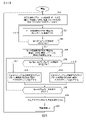
マイクロコントローラ118は、メモリ122に常駐するファームウェアにより制御されている状態で動作する。特定の実施形態では、ファームウェアは、スタートアップルーチン、最大電力点追尾(MPPT)動作ルーチン、及びシャットダウンルーチンを含む。図1、図4、及び図5を参照するに、これらのルーチンは以下のルーチンを含む:
1.スタートアップルーチン
The
1. 1. Startup routine
一旦、コントローラの電源が投入されて、基本機能がチェックされる302と、マイクロコントローラ118は、PVパネル102から受け取るVpv電圧をチェックし、当該電圧がメモリ122に記録されている所定の最小始動電圧よりも高い場合にのみ、当該マイクロコントローラはスタートアップルーチンを継続する。Vpv電圧が最小値を下回る場合、当該マイクロコントローラは、Vpvが最小値を超えるまで待機する。
Once the controller is turned on and the basic functions are checked 302, the
一旦、最小始動電圧に達すると、マイクロコントローラ118は、VFD114が生成する初期正弦波の周波数を設定する304。次に、マイクロコントローラ118は、正弦波の振幅(相RMS電圧)を周波数から、図3に図示され、かつメモリ122に格納されている電圧-周波数曲線(V-f曲線)を使用して決定する。様々な実施形態におけるメモリ122は、リードオンリメモリ、プログラマブルリードオンリメモリ、または電気的に消去可能かつ再書き込み可能なリードオンリメモリのうち1つ以上のリードオンリメモリを含み、V-f曲線は、必要に応じて、使用する特定のモータ106の種類に対応して決定される。V-f曲線は、ゼロを起点とするのではなく、最小のモータ相RMS電圧を最小周波数値に対応して与える電圧オフセット(Vmin)を有する。
-マイクロコントローラ118は、システム104の動作を、決定された周波数及び電圧をVFD114に信号SVFDを介して供給することにより開始する。その結果、周波数f1及び振幅相RMS電圧V1を有するAC信号がモータ106に供給される。
-次に、マイクロコントローラ118は、太陽光PV電流をフィードバックセンサ信号Ipv(太陽光PV電流)を介してチェックし306、Ipvが、特定のパーセンテージ(x%)の値だけ、前の読み取り値から減少する場合(Ipvnew<Ipvold*x%)、これは、モータ106が回転し始めたことを示している。特定の実施形態では、x%は10%である。他方、PV電流センサによる新規読み取り値(Ipv)が、前の読み取り値の所定パーセンテージx%以上である場合、モータ106は、未だ始動していないと判断されるので、マイクロコントローラは別のステップに進み、このステップでは、VFD114の動作周波数304をf2に増加させ、それに応じて、動作相電圧を別の相電圧V2に増加させる。百分率値x%(始動を認識するための閾値)は、適応的であり、ACモータ及び負荷の電力量とともに変化する。
-別の実施形態では、Ipvの減少を観察してモータ回転の正しい始動を確認するのではなく、マイクロコントローラ118は、モータ回転をモータ速度センサ(図示せず)で直接観察する。様々な実施形態では、モータ速度センサとして、磁石及び感知コイル、歯付きホイール、LED、及び光センサ、歯付きホイールセンサ及びリラクタンスセンサ、慣性スイッチ、またはこの技術分野で公知の任意の他の回転センサを挙げることができる。
-マイクロコントローラ118がVFD114の周波数をf2に信号SVFDを介して高くして、f2正弦波周波数を適切な電圧振幅V2で、可変駆動出力端子116に供給する場合。
-マイクロコントローラ118は、Ipvセンサが、新規の太陽光PV電流値が、初期値または前の値の所定パーセンテージx%未満になって、モータが回転し始めたことを意味するまで、またはモータ速度センサが適切な回転数を検出して、DC-DCコンバータ110がMPPT Regular Modeに移行するまで、VFD114の周波数及び電圧を増加させ続け、太陽光PV電流を、フィードバック信号Ipvを介してチェックし続ける。
-太陽光PV電流(Ipv)が、1つの周波数ステップから別の周波数ステップに変更するときに所定の値のパーセンテージx%だけ減少することがなく、周波数が、メモリ122に格納されている周波数の最大値に達する場合(最大周波数は、各モータ種類について公知である)、モータは、回転し始めておらず、マイクロコントローラは、VFD114を動作させるのを中止し、START-UP ROUTINEを所定の中断時間後に再び開始しようとする。これにより、HVACまたは冷凍システムの冷媒を加圧することにより発生する、または全水柱を井戸ポンプの後ろに射出することにより発生する負荷のような幾つかの高い始動負荷を低減することができる。
2.最大電力点追尾(MPPT)レギュラーモード
-一旦、マイクロコントローラ118が、モータが始動したという判断を下すと、DC-DCコンバータは、DC第2電圧112を事前設定値Vsetに、AC/DCモータドライブ114のパワースイッチQ3~Q8を直接制御している信号Sboostを介して調節する308。
-DCリンク112の調節は、DC-DCコンバータ110が、DCリンク112の電圧値を、当該電圧値が所望の値Vsetに達するまで、昇圧回路(図2)のパワースイッチQ1及びQ2の動作デューティサイクルを変化させることにより調整することを意味している。
-信号フィードバックVdcは、マイクロコントローラ118の測定用DC第2電圧112値である。
-Vdcフィードバック値がVset値よりも小さい場合、DC-DCコンバータのデューティサイクルにより、DC-DCコンバータのデューティサイクルが当該デューティサイクルの最大値に達するまで、Sboost信号の値が増加してDCリンク112の電圧値を増加させる。
-DC-DCコンバータ110が、DCリンク電圧112を、メモリ122に格納されている値により決まる事前設定値Vset、及び最大周波数未満の周波数に調節している状態では、メモリ122に格納されているMPPTアルゴリズムがマイクロコントローラ118上で実行されてVFD114のモータ周波数を増加させ、これは、相RMS電圧をそれに応じて、図3の電圧-周波数曲線に基づいて増加させることを伴う。これを行なうために、マイクロコントローラ118は、光電変換パネルから取り出される現在の電力を光電変換パネルから取り出された前の電力と比較する310。電力が増加した場合、マイクロコントローラは、可変周波数ドライブ114の周波数及び電圧を増加させ312、電力消費量が、太陽光パネル102の電力制限により増加しなかった場合、マイクロコントローラは、可変周波数ドライブ114の周波数及び電圧を減少させる314。
-VFDにより生成されるAC電力の周波数及び電圧を増加させることにより、モータに指示して、より高いRPMで回転させて、VFD114及びモータ106が消費する電力を増加させることにより、太陽光PVパネル102から取り出される電力を増加させる。
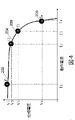
-周波数のこの増加は、段階的に行なわれ、第1段階202では、モータ周波数1(f1)をマイクロコントローラ110により設定し、周波数1で動作しているモータ106は、ポイント202(太陽光電流I1及び太陽光電圧V1)で動作するものとして図4に図示される太陽光PV電力に対応する。
-マイクロコントローラ118は次に、VFD114により生成されるモータ電力116の周波数(f2)を増加させ、より高い周波数の隣の動作ポイントは、太陽光PV電流(I2)がより大きく、かつ太陽光PV電圧V2がより小さいポイント204として図4に図示される。VFD周波数増加は、特定のモータ及び負荷に関する最大定格周波数を超えないように制限される。
-マイクロコントローラ118が、モータ周波数を増加し続ける場合、太陽光PVパネルから取得される電力(電力=IxV)が当該電力の最大値になるポイントが発生し、このポイントは図4のポイント206として図示されている。このアルゴリズムにより発見される最大電力点は、日射に伴って大きく変化する。
-周波数が増加し続ける(モータがより高速で回転していてより多くの電力を必要とする)場合、太陽光PVパネル102から出力される電力は、最大電力発生量に達すると減少し始め、太陽光PVパネルが、当該速度での、またはより速い速度でのモータ動作に必要な電力を供給することができないので、電圧が電流増加よりも急速に降下する(図4に図示されるポイント208におけるV-I曲線特性)。
-その結果、DCリンク電圧を維持するための十分な電力をパネルから供給することができないので、DCリンク電圧が降下する。
-一旦、マイクロコントローラが、DCリンク電圧が減少したことを感知する316と、マイクロコントローラは、VFDに現われる周波数を減少させて、より低い周波数ステップに戻して、dc-dcコンバータがDCリンク電圧調節を再度行なうことができるようにする。
-一旦、DCリンク電圧調節が行なわれ、マイクロコントローラ118が、当該DCリンク電圧が必要限界値内に収まっていることを感知すると、MPPTアルゴリズムは、VFD114の周波数増加を再び開始して、モータ106の回転速度を増加させる。DCリンク電圧値が減少して閾値Vfdropを下回る場合、マイクロコントローラは直ちに、動作周波数を所定の周波数減少値f2だけ減少させ、周波数減少値f2は、最大電力点追尾方式内で使用される周波数変化よりもずっと大きな周波数変化(周波数ステップ)である。この周波数がステップf2だけ減少することにより、DCリンク電圧が閾値Vfdropを上回る値に復帰することができない場合、マイクロコントローラ118は、DCリンク電圧が閾値Vfdropよりも大きくなるまで、動作周波数を別のf2だけ減少させる。
3.ストップルーチン
Once the minimum starting voltage is reached, the
-The
-Next, the
-In another embodiment, instead of observing a decrease in Ipv to confirm the correct start of motor rotation, the
-When the
-
-The solar PV current (Ipv) does not decrease by a percentage x% of a predetermined value when changing from one frequency step to another, and the frequency is the frequency stored in the
2. 2. Maximum Power Point Tracking (MPPT) Regular Mode
-Once the
-The adjustment of the DC link 112 is such that the DC-
-The signal feedback Vdc is the measurement DC
When the -Vdc feedback value is smaller than the Vset value, the duty cycle of the DC-DC converter increases the value of the Sboost signal until the duty cycle of the DC-DC converter reaches the maximum value of the duty cycle, and the DC link 112 Increase the voltage value of.
-The DC-
-Solar PV panel by instructing the motor to rotate at a higher RPM by increasing the frequency and voltage of the AC power generated by the VFD to increase the power consumed by the
-This increase in frequency is done in stages, in the
The
-When the
-If the frequency continues to increase (the motor is spinning faster and requires more power), the power output from the
-As a result, the DC link voltage drops because sufficient power cannot be supplied from the panel to maintain the DC link voltage.
-Once the microcontroller senses that the DC link voltage has decreased 316, the microcontroller reduces the frequency that appears in the VFD and returns it to the lower frequency step, and the dc-dc converter adjusts the DC link voltage. To be able to do it again.
-Once the DC link voltage adjustment is performed and the
3. 3. Stop routine
レギュラーモード動作状態では、マイクロコントローラ118は、太陽光PVパネル102の両端の電圧(Vpv信号)をチェックしている。Vpvの値がメモリ122に格納されている電力低下限界値よりも大きい値だけ低下して所定値Vd(マイクロコントローラのメモリに格納されている)になる場合、マイクロコントローラ118は、モータが回転を停止する必要があり、マイクロコントローラがVFD114の動作を停止させ318、モータ及びモータ114で駆動される負荷について必要に応じて所定期間だけ待機し320、START-UP ROUTINEに移行する。
-このようなスタート-ストップイベントが数回連続して発生する場合(試行回数に関する所定限界値が、マイクロコントローラのメモリに格納されている)、マイクロコントローラは、パネル上で利用可能な太陽光エネルギーが、モータを動作させるためには十分ではないという判断を下し、より長い待機時間Wsunだけアイドル状態になる。待機時間Wsun後、最小限の電圧がパネル上で利用可能であり日中条件であることを示している場合、コントローラは、START-UP ROUTINEに戻ることにより始動を再度試みる。
In the regular mode operating state, the
-When such a start-stop event occurs several times in a row (a predetermined limit on the number of trials is stored in the microcontroller's memory), the microcontroller has the solar energy available on the panel. However, it is determined that it is not enough to operate the motor, and it becomes idle for a longer standby time Wsun. After the standby time Wsun, if the minimum voltage is available on the panel and indicates daytime conditions, the controller will try to start again by returning to START-UP ROUTINE.
特定の実施形態では、モータ106は三相モータであり、可変周波数モータドライブ114は、三相交流電流を供給してモータ106を駆動する;別の実施形態では、モータ106は相分割形モータであり、VFD114は、モータ駆動相電源及び位相シフト始動電源または動作電源をモータ106に供給する。別の特定の実施形態では、モータ106は、始動キャパシタを含むモータ始動用集積回路を有する単相モータであり、VFD114はモータ106に単相AC電力を供給する。
In certain embodiments, the
特定の実施形態では、可変周波数モータドライブ114は、正弦波出力を供給してモータ106を駆動する。
In certain embodiments, the variable
別の実施形態では、図1の太陽光パネル102を、風力タービン発電システム及び関連する整流器に置き換えて、DC電力をDC-DCコンバータ110に供給する;このようなシステムでは、風力タービン回転速度センサを任意であるが、マイクロコントローラ118及びファームウェア122の入力として設けることができ、これは、風力タービン速度情報だけでなく、VFD114を調整するための電流および電圧情報を使用して、風力タービンの失速を防止して、モータ106への電力伝達率を最適化することができるように適合されている。
In another embodiment, the
更に別の実施形態では、図1の太陽光パネル102を、ガソリン、ディーゼル、ガスタービン、または水蒸気エンジン(水蒸気エンジンはピストンまたはタービンとすることができる)により駆動される発電機に置き換える;通常、関連する整流器で、発電機により生成される全てのACを整流し、DC電力をDC-DCコンバータ110に供給する。このようなシステムでは、スロットル入力がコントローラ104に供給され、システムは従って、可変比の電力伝達装置として機能することができる。可変比の電力伝達装置は、多くの用途を有しているが、構造及び多くの細かな動作(DCモータの使用を含む)が、現在記述されているシステムとは異なっており、米国海軍は、1918年~1947年の間のニューメキシコ級戦艦、テネシー級戦艦、及びコロラド級戦艦の主燃焼機関系の減速ギアではなく、可変比の電力伝達装置を操作していた。
In yet another embodiment, the
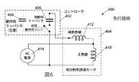
キャパシタ始動コントローラ402及び3線式単相モータ404を備える従来の相分割形モータシステム400(図6)は、始動用キャパシタ406及び制御リレー408をコントローラ402に備えている。モータ404は、主巻線410及び始動用補助巻線412を有する。制御リレー408は、始動用巻線412に直列接続されるキャパシタ406を、主巻線410に並列接続されるAC電源414にモータ始動中に接続する。制御リレー408は、一旦、モータが回転し始めると、キャパシタ406及び始動用巻線412との接続を解除する。キャパシタ406は、90度の位相シフトを、主巻線410に印加される電力と始動用巻線412に印加される電力との間に効果的に与える。全てではないが幾つかの従来のキャパシタ始動コントローラでは、別体のキャパシタCrun409を設けて、モータが動作してトルクを増加させている状態で始動用巻線412の所定部分を使用できるようにし、これらのコントローラでは、Crunは通常、Cstartよりもずっと小さな値を有するので、モータ始動サージ電流による動作時間中の電流及び電力消費を減少させ易くしている。この従来のモータシステム400は極めて広く使用されているが、このモータシステムは短所を有し、これらの短所の中でもとりわけ、モータを全動作周波数で始動するために必要なサージ電流及び電力が非常に大きいという短所がある。図1~図3を参照して説明されるMPPT可変周波数モータ制御システムは、以下に説明する図7の実施形態と併せて使用される。
A conventional phase split motor system 400 (FIG. 6) comprising a
この構成では、以下の関係式を記述することができる:
Vaux =VPhs-Vph1、式中、Vauxは、始動用巻線の両端の電圧である…(1)
Vmain =VPh2-VPh1 …………………(2)
In this configuration, the following relational expression can be written:
Vaux = VPhs-Vph1, in the equation, Vaux is the voltage across the starting winding ... (1)
Vmain = VPh2-VPh1 …………………… (2)
PhSを、始動用巻線として作用する補助巻線給電線として選択した場合、モータが回転し始めると直ぐに、補助巻線給電線への給電が遮断される(電流が補助巻線給電線を流れなくなる)。 When PhS is selected as the auxiliary winding feeder that acts as the starting winding, the feed to the auxiliary winding feeder is cut off as soon as the motor begins to rotate (current flows through the auxiliary winding feeder). Will disappear).
3線式モータを、補助巻線を使用して始動させることとは別に、モータは、電圧/周波数(V/F)比を一定に保ちながら、可変周波数モードで駆動されることになり、RMSは実効相電圧であり、fは当該実効相電圧の周波数である-上の段落で説明された通り。モータをV/fの関係を保ちながら自由に制御するために、ノード:Ph1,Ph2,及びPhSに現われる電圧波形が、方程式3~5に示す通りに生成される:
VPh1 =Vdc/2+Vdc/2*duty1*sin(x) …………………(3)
VphS =Vdc/2+Vdc/2*duty2*sin(x-θ) …………………(4)
VPh2 =Vdc/2+Vdc/2*duty3*sin(x-γ) …………………(5)
式中、3つの波形は全て、Vdc/2、すなわち入力DC電圧の半分だけずれている。更に、波形VphSが、VPh1に対して角度θだけずれているのに対し、波形VPh2は、VPh1に対して角度γだけずれている。
Apart from starting the 3-wire motor using auxiliary windings, the motor will be driven in variable frequency mode while keeping the voltage / frequency (V / F) ratio constant, RMS. Is the effective phase voltage and f is the frequency of the effective phase voltage-as explained in the paragraph above. In order to freely control the motor while maintaining the V / f relationship, the voltage waveforms appearing in the nodes: Ph1, Ph2 and PhS are generated as shown in equations 3-5:
VPh1 = Vdc / 2 + Vdc / 2 * duty1 * sin (x) …………………… (3)
VphS = Vdc / 2 + Vdc / 2 * duty2 * sin (x-θ) …………………… (4)
VPh2 = Vdc / 2 + Vdc / 2 * duty3 * sin (x-γ) …………………… (5)
In the equation, all three waveforms are deviated by Vdc / 2, that is, half of the input DC voltage. Further, the waveform VphS is deviated by an angle θ with respect to VPh1, while the waveform VPh2 is deviated by an angle γ with respect to VPh1.
これらの3つの電圧波形は、マイクロコントローラを使用してPWM信号をVFDのスイッチング素子に印加することにより生成することができる。 These three voltage waveforms can be generated by applying a PWM signal to the switching element of the VFD using a microcontroller.
PhSが始動用巻線給電線である場合、これは、Ph2が主巻線給電線であることを意味し、上記方程式が示す通り、主巻線の両端の電圧は、Vmain =Vph1-VPh2であるので、目的が、最大振幅が主巻線に現われることである場合、VPh2及びVPh1の電圧波形の振幅を等しくする(duty 1 = duty3)必要があるが、反対方向に等しくする必要がある(γ = 180°)。主巻線の振幅は、所定の入力DC電圧についても最大化する必要があるので、以下の方程式2が成り立つ: When PhS is a starting winding feeder, this means that Ph2 is the main winding feeder, and as the equation above shows, the voltage across the main winding is Vmain = Vph1-VPh2. Therefore, if the purpose is for the maximum amplitude to appear in the main winding, then the amplitudes of the voltage waveforms of VPh2 and VPh1 need to be equal (duty 1 = duty 3), but in the opposite direction (duty 3). γ = 180 °). Since the amplitude of the main winding also needs to be maximized for a given input DC voltage, the following equation 2 holds:
Vmain = Vph1-VPh2 => Vmain = Vdc*duty1*sin(x) ………(6) Vmain = Vph1-VPh2 => Vmain = Vdc * duty1 * sin (x) ……… (6)
更に、補助巻線に現われる電圧波形は、主巻線に現われる電圧波形に対して約90°ずれた位相とする必要があるが、同じ振幅を有する必要があり、この関係は、方程式6から、以下の通りに導出することができる:
Vaux= Vdc*duty1*sin(x-90°) ………(7)
Further, the voltage waveform appearing in the auxiliary winding must have a phase shifted by about 90 ° with respect to the voltage waveform appearing in the main winding, but must have the same amplitude, and this relationship can be found in Equation 6 from Equation 6. It can be derived as follows:
Vaux = Vdc * duty1 * sin (x-90 °) ……… (7)
方程式7を方程式1と組み合わせる場合、VPhsについての波形方程式が以下の通りに得られる:
Vaux =VphS-VPh1
=> VphS=Vaux+VPh1 = Vdc/2 + Vdc/2*duty1*sin(x) + Vdc*duty1*sin(x-90°)
=> VPhs= Vdc/2 + Vdc*duty1*(sin(x-90°) +1/2*sin(x)) ………(8)
When equation 7 is combined with equation 1, the wave equation for VPhs is obtained as follows:
Vaux = VphS-VPh1
=> VphS = Vaux + VPh1 = Vdc / 2 + Vdc / 2 * duty1 * sin (x) + Vdc * duty1 * sin (x-90 °)
=> VPhs = Vdc / 2 + Vdc * duty1 * (sin (x-90 °) + 1/2 * sin (x)) ……… (8)
方程式8は、VPhS波形について方程式4の形式で記述される必要があり、このような種類の変換を「任意の位相シフト」変換と呼び、一般的な規則は、以下の通りである:
A*sinX+B*sin(X+Y) = C*sin(X+Z) ………(9)
式中、係数Cは以下の通りに計算することができる:
C=sqrt(A2+B2+2*A*B*cos(Y) ………(10)
更に、角度Zは以下の通りに計算することができる:
Z=atan(B*sin(Y)/(A+B*cos(Y)) ………(11)
Equation 8 needs to be described for the VPhS waveform in the form of Equation 4, and this kind of transformation is called an "arbitrary phase shift" transformation, and the general rules are as follows:
A * sinX + B * sin (X + Y) = C * sin (X + Z) ……… (9)
In the equation, the coefficient C can be calculated as follows:
C = sqrt (A2 + B2 + 2 * A * B * cos (Y) ……… (10)
In addition, the angle Z can be calculated as follows:
Z = atan (B * sin (Y) / (A + B * cos (Y)) ……… (11)
方程式10及び11を使用すると、未知のduty2及びθの解を方程式4から求めることができるので、以下の関係が得られる:
duty2 = 2.23*duty1
angle θ = 63°
Using equations 10 and 11, the solution of the unknown duty 2 and θ can be obtained from equation 4, so that the following relationship is obtained:
duty2 = 2.23 * duty1
angle θ = 63 °
次に、図Xに示す三相インバータの電圧波形は以下の通りに表わすことができる:
VPh1 =Vdc/2+Vdc/2*duty*sin(x) …………………(12)
VphS =Vdc/2+Vdc/2*2.23*duty*sin(x-63°) …………………(13)
VPh2 =Vdc/2+Vdc/2*duty*sin(x-180°) …………………(14)
式中、dutyは、ACモータの可変周波数動作に対応する相rms電圧と周波数の関係を表わすV/f比である。
Next, the voltage waveform of the three-phase inverter shown in FIG. X can be expressed as follows:
VPh1 = Vdc / 2 + Vdc / 2 * duty * sin (x) …………………… (12)
VphS = Vdc / 2 + Vdc / 2 * 2.23 * duty * sin (x-63 °) …………………… (13)
VPh2 = Vdc / 2 + Vdc / 2 * duty * sin (x-180 °) …………………… (14)
In the equation, duty is a V / f ratio representing the relationship between the phase rms voltage and frequency corresponding to the variable frequency operation of the AC motor.
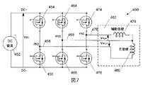
図7は、3線式相分割形モータをシングルエンド型DC電源452で始動及び動作させるように構成される周波数制御可能な相分割形DC-AC可変モータドライブインバータ450の概略図である。Ph2に対して正側のパワースイッチング素子454及びPh2に対して負側のパワースイッチング素子456を交互に駆動して、位相2(Ph2)AC信号458を供給して、3線式相分割形モータ462の主巻線460を駆動する。同様に、Ph1に対して正側の別のパワースイッチング素子464及びPh1に対して負側の別のパワースイッチング素子466を交互に駆動して、位相1(Ph1)AC信号468を供給して、3線式相分割形モータ462の始動用巻線470の第1端子及び主巻線460の第2端子の接続先の共通接続端子を駆動する。最後に、PhSに対して正側の別のパワースイッチング素子474及びPhSに対して負側の別のパワースイッチング素子476を交互に駆動して、オフセット位相3(PhS)AC信号478を供給して、3線式相分割形モータ462の始動用巻線470の第2端子の接続先の接続端子を駆動する。
FIG. 7 is a schematic diagram of a frequency-controllable phase-divided DC-AC variable
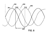
始動動作状態では、周波数制御可能な相分割形DC-AC可変モータドライブインバータ450を動作させて図8に示す波形を供給する。特定の実施形態では、パワースイッチング素子454,456,464,466,474,476は、単なるスイッチングトランジスタではなく、高周波スイッチング変換方式を使用し、かつ正弦波形を供給するように適合させた双方向性電力伝達素子である。正側のパワースイッチング素子454及び負側のパワースイッチング素子456を動作させて、始動周波数の正弦波形490を主巻線460のPh2接続端子に供給するのに対し、正側のパワースイッチング素子464及び負側のパワースイッチング素子466を動作させて、始動周波数の正弦波形492を主巻線460のPh1接続端子に供給する。モータ回転を開始するために、PhSに対して正側のパワースイッチング素子474及びPhSに対して負側のパワースイッチング素子476を動作させて、始動周波数の正弦波形494を、制御可能な位相オフセット496を持たせて始動用巻線470のPhS接続端子に供給する。一旦、モータ回転が始まると、正側のパワースイッチング素子474及び負側のパワースイッチング素子476を導通遮断させて始動用巻線470との接続を解除するとともに、正側のパワースイッチング素子454,464及び負側のパワースイッチング素子456,466に対する駆動が継続して、電力を主巻線460に供給し続けることによりモータを動作させる。
In the starting operation state, the frequency-controllable phase-divided DC-AC variable
特定の実施形態では、始動状態において、位相シフト496は、始動用巻線電圧PhS 494,478を負側の駆動電圧Ph1 468,492よりも63度だけ遅らせて効率を最適化するように設定される。
In certain embodiments, in the starting state, the
図9は、3線式誘導モータを始動及び動作させるように構成される別の相分割形インバータの概略図である。この実施形態では、DC電源502,504ペアを使用して、正側の給電線552及び負側の給電線554に事実上中性の接続端子506を与える。これらのDC電源のうち一方のDC電源502は、前に説明したDCリンク電圧であり、他方のDC電源504は、DC電源502により駆動される高周波スイッチングDC-DCコンバータまたはチャージポンプである。
FIG. 9 is a schematic diagram of another phase split inverter configured to start and operate a 3-wire induction motor. In this embodiment,
中性506が図7のPh1 468に置き換わる。正側のパワースイッチング素子510及び負側のパワースイッチング素子514は、Ph2ライン518を駆動してモータの主巻線520を駆動し、ACモータ駆動相458,468,478がゼロとハイDC電圧との間で振れる図7の実施形態とは異なり、この実施形態では、ACモータ駆動相518及び522は、中性506に対して正側及び負側の両方に振れる。正側のパワースイッチング素子512及び負側のパワースイッチング素子516は、PhSライン522を駆動してモータの補助巻線または始動用巻線524を駆動するように構成される。幾つかの実施形態では、正側のパワースイッチング素子512及び負側のパワースイッチング素子516は、始動用巻線524に直接接続される。この実施形態では、正側電源線552は、正側のパワースイッチング素子510,512に接続され、負側電源線554は、負側のパワースイッチング素子514,516に接続される。
Neutral 506 replaces
図7及び図9の可変周波数モータドライバは、パワースイッチング素子454,456,464,466,474,476,510,512,514,516をコントローラ118(図1)により制御されている状態で動作させ、コントローラ118は、可変周波数動作及び可変電圧動作を可能にし、Ph1 468,494,518に対するPh2 458,490,506とPhS 478,494,522の位相関係の制御を可能にする。Ph1とPhSの位相関係は、始動用キャパシタまたは動作用キャパシタ(図6)のようなリアクティブ素子を介した電圧降下によるのではなく、コントローラにより直接合成されるので、この位相関係は、高速の始動動作及び効率的な給電動作について最適化することができる。
The variable frequency motor driver of FIGS. 7 and 9 operates the power switching element 454,456,464,466,474,476,510,512,514,516 in a state of being controlled by the controller 118 (FIG. 1). ,
1つの実施形態では、コントローラ118のメモリに格納されているオフセットDPhase 123(図1)を主巻線出力Ph2の電流位相に付加してVphSの電流位相を設定する;これらの電流位相を使用して、出力VPh2,VPh1、及びVphSを駆動する正側の駆動パワースイッチング素子及び負側の駆動パワースイッチング素子への入力パルスを合成する。
In one embodiment, the offset DPhase 123 (FIG. 1) stored in the memory of the
図7、図8、及び図9を参照して説明される実施形態では、モータ動作を始動周波数で開始し、始動周波数は、フル最大電力動作周波数よりもずっと低い。一旦、モータ回転が始まると、本システムは、利用可能な電力を超えるまで、またはフル定格動作周波数に達するまで、当該システムの動作周波数及び動作電圧をランプさせる。利用可能な電力を超える場合、動作周波数を減少させて電力を、これまでに説明してきた最大電力点追尾アルゴリズムに従って節約する。 In embodiments described with reference to FIGS. 7, 8 and 9, motor operation is initiated at the starting frequency, where the starting frequency is much lower than the full maximum power operating frequency. Once the motor rotation begins, the system ramps the operating frequency and voltage of the system until it exceeds the available power or reaches the full rated operating frequency. If it exceeds the available power, the operating frequency is reduced to save power according to the maximum power point tracking algorithm described so far.
補助巻線または始動用巻線470,524(図7、図9)から見て、当該巻線の両端に現われる電圧を主巻線460,520の両端に現われる電圧よりも事実上下げることができることに注目されたい。これは、主巻線460,520から見て、Ph2 458,506とPh1 468,518との間の電圧が180度離れているのに対し、補助巻線470または始動用巻線524から見て、Ph1 468,512とPhS 478,522との間の実効AC電圧が、PhSとPh1の位相差が180度ではないので小さくなっているからであり;Ph2とPhSの位相差がゼロである状態では、電圧差PhS-Ph1は最大であるが、PhSがPh1に一致してPh2とPhSの位相差が180度である状態では、電圧差PhS-Ph1はゼロになるからであるという結果である。本願発明者らは、従来、90度の位相差を利用して3線式キャパシタ始動モータを始動させるが、他の位相差により、より大きな電圧が始動用巻線の両端に現われるので、動作がより良好になるという知見を得ている。具体的には、DC電源452,502,504のより低いDC電圧、及びそれに応じてPh2、Ph1、及びPhSに現われるより低いAC電圧は、このようなモータを、PhSがPh1よりも位相が約117度進む(PhSがPh2よりも位相が63度遅れることに相当する)ように位相差を持たせてPhSをフル電圧に能動的に駆動することにより始動及び動作させている状態で使用することができる。様々な実施形態では、PhSはPh1よりも位相が、58度~68度遅れる、またはPh2よりも位相が112度~122度進んで、より高い実効電圧を、Ph2から十分なオフセットがある状態で補助巻線または始動用巻線の両端に供給することによりモータを始動させることができる。本コントローラにより、始動用巻線PhSの位相をファームウェアで調整して、このより高い電圧を始動用巻線の両端に供給することができる。
Seen from the auxiliary windings or starting windings 470,524 (FIGS. 7 and 9), the voltage appearing across the windings can be effectively lower than the voltage appearing across the main windings 460,520. Please pay attention to. This is because the voltage between
本文書の目的として、ファームウェアは、メモリに整然と順番に格納されている機械読み取り可能な命令であり、機械読み取り可能な命令を供給して、マイクロコントローラを適合させて特定のタスクを実行する、例えば光電変換パネルの最大電力点を、可変周波数モータドライブが取り出す電力を調整することにより、第2DC電圧を調節することにより追尾する。
組み合わせ
For the purposes of this document, firmware is a machine-readable instruction that is neatly and sequentially stored in memory, supplying machine-readable instructions to adapt a microcontroller to perform a particular task, eg. The maximum power point of the photoelectric conversion panel is tracked by adjusting the second DC voltage by adjusting the power taken out by the variable frequency motor drive.
combination
本明細書において記載されるシステムの特徴は、様々な態様で組み合わせることができる。本願発明者らが予測する特徴の組み合わせの中でもとりわけ、以下の特徴を挙げることができる。 The features of the system described herein can be combined in various ways. Among the combinations of features predicted by the inventors of the present application, the following features can be mentioned.
Aと表記されるシステムは、AC電動モータと;少なくとも1つの光電変換パネルと;電力を少なくとも1つの光電変換パネルから受け取り、第2DC電圧を供給するように接続されるDC-DCコンバータと;第2DC電圧を受け取り、AC電力をAC電動モータに供給するように接続される可変周波数モータドライブと;第2DC電圧を調節し、最大電力点追尾ファームウェアを使用して可変周波数モータドライブの周波数を調整することにより、電力出力を最適化するように構成されるマイクロコントローラと、を含む。 The system, labeled A, is an AC motor; with at least one photoelectric conversion panel; with a DC-DC converter connected to receive power from at least one photoelectric conversion panel and supply a second DC voltage; With a variable frequency motor drive connected to receive 2DC voltage and supply AC power to the AC electric motor; adjust the 2nd DC voltage and adjust the frequency of the variable frequency motor drive using the maximum power point tracking firmware. Includes a microcontroller configured to optimize the power output, and thereby.
AAと表記されるシステムは、Aと表記されるシステムを含み、マイクロコントローラは更に、AC電動モータに供給されるAC電力の電圧を調整するように構成される。 The system labeled AA includes the system labeled A, and the microcontroller is further configured to regulate the voltage of the AC power delivered to the AC motor.
ABと表記されるシステムは、AまたはAAと表記されるシステムを含み、マイクロコントローラは、AC電動モータに供給されるAC電力の電圧を、AC電力の電圧がAC電力の周波数とともに直線的に増加するように調整するように構成される。 The system labeled AB includes the system labeled A or AA, where the microcontroller increases the voltage of the AC power supplied to the AC electric motor, the voltage of the AC power linearly increases with the frequency of the AC power. It is configured to adjust to.
ADと表記されるシステムは、AA,AB,またはAと表記されるシステムを含み、マイクロコントローラは、ACモータが回転し始めるまで第2DC電圧及びAC電力の周波数を漸増させるように適合させたファームウェアを有し、マイクロコントローラは、ACモータが回転し始めたことを、少なくとも1つの光電変換パネルから受け取る電流の変化を検出することにより認識する。 The system labeled AD includes the system labeled AA, AB, or A, and the microcontroller is tailored to increase the frequency of the second DC voltage and AC power until the AC motor begins to rotate. The microcontroller recognizes that the AC motor has begun to rotate by detecting a change in the current received from at least one photoelectric conversion panel.
AEと表記されるシステムは、AA,AB,AD,またはAと表記されるシステムを含み、最大電力点追尾ファームウェアは、機械読み取り可能な命令を含むことにより、少なくとも1つの光電変換パネルから受け取る最大可能電力を探索しながら、第2DC電圧レベルを、可変周波数モータドライブの周波数に比例して増加する所定電圧に調節しながら、可変周波数モータドライブの周波数を段階的に変化させる。 The system labeled AE includes the system labeled AA, AB, AD, or A, and the maximum power point tracking firmware receives from at least one photoelectric conversion panel by including machine readable instructions. While searching for possible power, the frequency of the variable frequency motor drive is changed stepwise while adjusting the second DC voltage level to a predetermined voltage that increases in proportion to the frequency of the variable frequency motor drive.
AEと表記されるシステムは、AA,AB,AD,またはAと表記されるシステムを含み、最大電力点追尾ファームウェアは、機械読み取り可能な命令を含むことにより、第2DC電圧を調整して、最大可能電力を少なくとも1つの光電変換パネルから取得するとともに、ファームウェアは、機械読み取り可能な命令を含むことにより、可変周波数モータドライブの動作周波数を調整する。 The system labeled AE includes the system labeled AA, AB, AD, or A, and the maximum power point tracking firmware adjusts the second DC voltage by including machine-readable instructions to maximize. While obtaining the possible power from at least one photoelectric conversion panel, the firmware adjusts the operating frequency of the variable frequency motor drive by including machine readable instructions.
AFと表記されるシステムは、AA,AB,AD,AE,またはAと表記されるシステムを含み、最大電力点追尾ファームウェアは、第2DC電圧を監視して、前記第2DC電圧が減少して所定閾値を下回る場合に、可変周波数モータドライブの周波数を減少させるように適合させた機械読み取り可能な命令を含む。 The system described as AF includes a system described as AA, AB, AD, AE, or A, and the maximum power point tracking firmware monitors the second DC voltage and determines that the second DC voltage is reduced. Includes machine-readable instructions adapted to reduce the frequency of variable frequency motor drives below the threshold.
AGと表記されるシステムは、AA,AB,AD,AE,AF,またはAと表記されるシステムを含み、システムは、AC電動モータの始動不具合を検出し、AC電動モータが始動できない場合に、可変周波数モータドライブを再試行時間の間停止し、再試行時間後に、AC電動モータの始動を再試行するように構成される。 The system labeled AG includes the system labeled AA, AB, AD, AE, AF, or A, where the system detects a start failure of the AC motor and fails to start the AC motor. The variable frequency motor drive is configured to stop for a retry time and then retry the start of the AC motor after the retry time.
AHと表記されるシステムは、AA,AB,AD,AE,AF,またはAJ,もしくはAと表記されるシステムを含み、AC電力は、AC電動モータの主巻線に接続される第1相AC電力と、AC電動モータの始動用巻線に接続される始動相AC電力と、を含み、第1相AC電力及び始動相AC電力は、非ゼロの位相シフトだけずれている。 The system labeled AH includes the system labeled AA, AB, AD, AE, AF, or AJ, or A, and the AC power is the first phase AC connected to the main winding of the AC motor. The first phase AC power and the starting phase AC power are offset by a non-zero phase shift, including the power and the starting phase AC power connected to the starting winding of the AC motor.
AJと表記されるシステムは、AHと表記されるシステムを含み、非ゼロの位相シフトは、58度~68度である、または112度~122度である。 The system described as AJ includes the system described as AH, and the non-zero phase shift is 58 degrees to 68 degrees, or 112 degrees to 122 degrees.
AKと表記されるシステムは、AA,AB,AD,AE,AF,AG,AH,AJ,またはAと表記されるシステムを含み、AC電力は更に、第1相AC電力の位相から180度ずれた第3相AC電力を含み、第3相AC電力は、始動用巻線及び主巻線の両方に接続される。 The system labeled AK includes the system labeled AA, AB, AD, AE, AF, AG, AH, AJ, or A, and the AC power is further 180 degrees out of phase with the first phase AC power. Including the third phase AC power, the third phase AC power is connected to both the starting winding and the main winding.
第1DC電圧を供給するDC制限電源により給電されるACモータを動作させるBと表記される方法は:DC制限電源からの電力を第2DC電圧に変換することと;第2DC電圧の電力を第1AC周波数のACモータ電圧及び第1AC電圧に変換することと;ACモータ電圧をACモータに供給することと;ACモータの始動を検出することと;ACモータの始動後、電圧及びACモータ電圧の周波数を、DC電源の最大周波数または限界周波数のいずれかに達するまで増加させることを含む。 The method described as B for operating the AC motor powered by the DC limiting power supply that supplies the first DC voltage is: converting the power from the DC limiting power supply to the second DC voltage; and converting the power of the second DC voltage to the first AC. Converting to AC motor voltage and first AC voltage of frequency; Supplying AC motor voltage to AC motor; Detecting AC motor start; After AC motor start, voltage and AC motor voltage frequency Includes increasing until either the maximum or limit frequency of the DC power supply is reached.
BAと表記される方法は、Bと表記される方法を含み、ACモータ電圧は、第1のAC相及び始動用のAC相を含み、第1の交流相及び始動用の交流相は、位相が58度~68度、または112度~122度だけ異なる。 The method described as BA includes the method described as B, the AC motor voltage includes the first AC phase and the starting AC phase, and the first AC phase and the starting AC phase are in phase. Is different by 58 degrees to 68 degrees, or 112 degrees to 122 degrees.
BBと表記される方法は、BまたはBAと表記される方法を含み、DC電源の限界は、DC電源の電圧をACモータ電圧の周波数が増加するときに監視し、ACモータ電圧の周波数が僅かに増加すると、DC電源の電圧が所定パーセンテージだけ降下し始めて、所定パーセンテージの電圧降下限界値を超えるようになる時点を判断することにより決定される。 The method described as BB includes the method described as B or BA, the limit of the DC power supply monitors the voltage of the DC power supply as the frequency of the AC motor voltage increases, and the frequency of the AC motor voltage is slight. When it increases to, it is determined by determining when the voltage of the DC power supply begins to drop by a predetermined percentage and exceeds the voltage drop limit value of the predetermined percentage.
第1DC電圧を供給するDC制限電源により給電されるACモータを動作させる方法は:DC制限電源からの電力を第2DC電圧に変換することと;第2DC電圧の電力を第1AC周波数のACモータ電圧及び第1AC電圧に変換することと;ACモータ電圧をACモータに供給することと;ACモータの始動を検出することと;ACモータの始動後、ACモータドライブの周波数を変化させて、DC制限電源の最大電力点(MMP)を探索することとを含む。 The method of operating the AC motor powered by the DC limiting power supply that supplies the first DC voltage is to convert the power from the DC limiting power supply to the second DC voltage; the power of the second DC voltage is the AC motor voltage of the first AC frequency. And to convert to the first AC voltage; to supply the AC motor voltage to the AC motor; to detect the start of the AC motor; after the start of the AC motor, change the frequency of the AC motor drive to limit the DC. Includes searching for the maximum power point (MMP) of the power source.
DC制限電圧が、光電変換パネル及び風力タービンからなるグループから選択される装置から供給される請求項15に記載の方法。 15. The method of claim 15, wherein the DC limiting voltage is supplied by an appliance selected from the group consisting of photoelectric conversion panels and wind turbines.
変更を上記方法及びシステムに、本発明の範囲から逸脱しない限り加えることができる。従って、上の説明に含まれる主題、または添付の図面に図示される主題は、例示として解釈されるべきであり、限定的に解釈されてはならないことに留意されたい。以下の特許請求の範囲は、本明細書において記載される全ての広範な特徴及び特定の特徴のみならず、言語の問題として、言語のなかに含意されると言える本方法及びシステムの範囲の全ての記述を包含するものとする。 Modifications can be made to the above methods and systems as long as they do not deviate from the scope of the invention. It should be noted, therefore, that the subject matter contained in the above description, or the subject matter illustrated in the accompanying drawings, should be construed as an example and should not be construed in a limited manner. The following claims cover not only all the broad features and specific features described herein, but also the entire scope of the methods and systems that can be said to be implied in the language as a matter of language. It shall include the description of.
Claims (14)
AC電動モータと、
少なくとも1つの光電変換パネルと、
前記少なくとも1つの光電変換パネルから電力を受け取り、第2のDC電圧を提供するように結合されているDC-DCコンバータと、
前記第2のDC電圧を受け取り、AC電力を前記AC電動モータに提供するように結合されている可変周波数モータドライブと、
前記第2のDC電圧を所定の値に調節するように構成されているマイクロコントローラと
を備え、
前記マイクロコントローラは、前記AC電動モータが回転し始めるまで、前記第2のDC電圧と前記AC電力の周波数とを徐々にかつ同時に増加させるように構成されており、
前記マイクロコントローラは、前記少なくとも1つの光電変換パネルから受け取る電流の変化を検出することによって、前記AC電動モータが回転し始めたことを検出することと、前記マイクロコントローラが最大電力点追尾ファームウェアを使用し始めた場合に、前記可変周波数モータドライブの周波数を限界まで増加させることとを行うように構成されており、前記増加させることは、複数の段階で行われ、各段階では、前記可変周波数モータドライブの周波数が周波数増加値だけ増加され、かつ、前記少なくとも1つの光電変換パネルから前記AC電動モータへの電力伝達率を最大化することを目的として、前記第2のDC電圧が閾値よりも多く降下した場合に前記最大電力点追尾ファームウェアが前記可変周波数モータドライブの周波数を減少させることによって、前記第2のDC電圧を前記所定値に調節しながら行われ、前記減少させることは、複数の段階で行われ、各段階では、前記可変周波数モータドライブの周波数が周波数減少値だけ減少され、前記周波数増加値は、前記周波数減少値よりも小さい、システム。 It is a system, and the system is
AC electric motor and
With at least one photoelectric conversion panel,
A DC-DC converter that receives power from the at least one photoelectric conversion panel and is coupled to provide a second DC voltage.
A variable frequency motor drive that receives the second DC voltage and is coupled to provide AC power to the AC motor.
It comprises a microcontroller configured to adjust the second DC voltage to a predetermined value.
The microcontroller is configured to gradually and simultaneously increase the second DC voltage and the frequency of the AC power until the AC electric motor begins to rotate.
The microcontroller detects that the AC electric motor has started to rotate by detecting a change in the current received from the at least one photoelectric conversion panel, and the microcontroller uses the maximum power point tracking firmware. It is configured to increase the frequency of the variable frequency motor drive to the limit when it starts to increase, and the increase is performed in a plurality of stages, and in each stage, the variable frequency motor is used. The second DC voltage is greater than the threshold for the purpose of increasing the frequency of the drive by the frequency increase value and maximizing the power transfer rate from the at least one photoelectric conversion panel to the AC electric motor. When the voltage drops, the maximum power point tracking firmware reduces the frequency of the variable frequency motor drive to adjust the second DC voltage to the predetermined value, and the reduction is performed in a plurality of steps. In each step, the frequency of the variable frequency motor drive is decremented by the frequency decrement value, and the frequency increase value is smaller than the frequency decrement value, the system.
前記制限されたDC電源からの電力を第2のDC電圧に変換することと、
前記第2のDC電圧を所定の値に調節することと、
第2のACモータ電圧を前記ACモータの始動用巻線に提供しながら、前記第2のDC電圧からの電力を第1のAC周波数で前記ACモータの主巻線に印加される第1のACモータ電圧に変換することであって、前記第2のACモータ電圧は、前記第1のACモータ電圧よりも大きい、ことと、
前記ACモータが始動するまで、前記第1および第2のACモータ電圧および前記第1のAC周波数を、それぞれ、低い値から前記ACモータの動作電圧および動作周波数に到達するように増加させることによって傾斜させることと、
前記制限されたDC電源から取り出される電流の減少を検出することによって、前記ACモータの始動を検出することと、
前記ACモータの始動後、最大周波数に到達するまで、または、前記第2のDC電圧が前記所定の値未満に減少する周波数に到達するまで、前記第1のACモータ電圧および第1のAC周波数を比例して増加させながら、前記ACモータの始動用巻線を接続解除することであって、前記第1のAC周波数は、複数の段階で増加し、各段階では、前記第1のAC周波数が周波数増加値だけ増加される、ことと、
前記第2のDC電圧の減少を検出することと、
複数の段階で前記第1のAC周波数を減少させることにより、前記第2のDC電圧が前記所定の電圧まで復帰することを可能にすることであって、各段階では、前記第1のAC周波数が周波数減少値だけ減少され、前記周波数増加値は、前記周波数減少値よりも小さい、ことと
を含む、方法。 A method of operating an AC motor powered by a limited DC power supply that provides a first DC voltage.
Converting the power from the limited DC power supply to a second DC voltage,
Adjusting the second DC voltage to a predetermined value and
A first application of power from the second DC voltage to the main winding of the AC motor at a first AC frequency while providing a second AC motor voltage to the starting winding of the AC motor. By converting to an AC motor voltage, the second AC motor voltage is larger than the first AC motor voltage.
By increasing the first and second AC motor voltages and the first AC frequency from lower values to reach the operating voltage and operating frequency of the AC motor, respectively, until the AC motor is started. To tilt and
Detecting the start of the AC motor by detecting a decrease in the current drawn from the limited DC power supply.
After starting the AC motor, the first AC motor voltage and the first AC frequency are reached until the maximum frequency is reached, or until the frequency at which the second DC voltage decreases below a predetermined value is reached. Is to disconnect the starting winding of the AC motor while increasing proportionally, the first AC frequency is increased in a plurality of stages, and the first AC frequency is increased in each stage. Is increased by the frequency increase value , and
Detecting the decrease in the second DC voltage and
By reducing the first AC frequency in a plurality of stages, it is possible to return the second DC voltage to the predetermined voltage , and in each stage, the first AC frequency. Is reduced by a frequency decrease value, the frequency increase value being smaller than the frequency decrease value, and the like.
前記第1相のAC電力および前記始動相のAC電力は、58度~68度または112度~122度の位相シフトだけずれており、
前記AC電動モータが始動したと決定され、かつ、前記AC電力が閾値周波数に到達した後に前記始動相のAC電力がオフにされる、請求項1に記載のシステム。 The AC electric motor is a phase split type motor, and the AC power is coupled to the AC power of the first phase coupled to the main winding of the AC electric motor and the starting winding of the AC electric motor. Including the AC power of the starting phase
The AC power of the first phase and the AC power of the starting phase are shifted by a phase shift of 58 degrees to 68 degrees or 112 degrees to 122 degrees.
The system according to claim 1, wherein it is determined that the AC electric motor has started, and the AC power of the starting phase is turned off after the AC power reaches a threshold frequency.
Applications Claiming Priority (3)
| Application Number | Priority Date | Filing Date | Title |
|---|---|---|---|
| US201562240979P | 2015-10-13 | 2015-10-13 | |
| US62/240,979 | 2015-10-13 | ||
| PCT/US2016/056618 WO2017066307A1 (en) | 2015-10-13 | 2016-10-12 | Variable speed maximum power point tracking, solar electric motor controller for induction and permanent magnet ac motors |
Publications (3)
| Publication Number | Publication Date |
|---|---|
| JP2018530840A JP2018530840A (en) | 2018-10-18 |
| JP2018530840A5 JP2018530840A5 (en) | 2019-11-07 |
| JP7061760B2 true JP7061760B2 (en) | 2022-05-02 |
Family
ID=58517816
Family Applications (1)
| Application Number | Title | Priority Date | Filing Date |
|---|---|---|---|
| JP2018519852A Active JP7061760B2 (en) | 2015-10-13 | 2016-10-12 | Variable speed maximum power point tracking, solar induction electric motor controller, and permanent magnet AC motor |
Country Status (9)
| Country | Link |
|---|---|
| US (1) | US10931220B2 (en) |
| EP (1) | EP3362867B1 (en) |
| JP (1) | JP7061760B2 (en) |
| CN (1) | CN108431719B (en) |
| AU (1) | AU2016338999B2 (en) |
| DK (1) | DK3362867T3 (en) |
| ES (1) | ES2894360T3 (en) |
| IL (1) | IL258401B (en) |
| WO (1) | WO2017066307A1 (en) |
Families Citing this family (13)
| Publication number | Priority date | Publication date | Assignee | Title |
|---|---|---|---|---|
| KR101783121B1 (en) * | 2016-01-18 | 2017-09-28 | 엘에스산전 주식회사 | Inverter |
| US10483887B2 (en) | 2017-08-11 | 2019-11-19 | Rolls-Royce North American Technologies, Inc. | Gas turbine generator temperature DC to DC converter control system |
| US10476417B2 (en) * | 2017-08-11 | 2019-11-12 | Rolls-Royce North American Technologies Inc. | Gas turbine generator torque DC to DC converter control system |
| US10491145B2 (en) | 2017-08-11 | 2019-11-26 | Rolls-Royce North American Technologies Inc. | Gas turbine generator speed DC to DC converter control system |
| SG11202002925TA (en) | 2017-10-05 | 2020-04-29 | Carrier Corp | Multi power converter unit for a trailer refrigeration unit |
| US10840831B2 (en) | 2018-02-27 | 2020-11-17 | Premier Energy Holdings, Inc. | Solar hybrid solution for single phase starting capacitor motor applications with grid start |
| US11855558B2 (en) | 2018-02-27 | 2023-12-26 | Premier Energy Holdings, Inc. | AC start, solar run hybrid solution for single phase, starting capacitor, motor applications with solar power measurement |
| US10560033B2 (en) | 2018-02-27 | 2020-02-11 | Suntech Drive, Llc | Solar hybrid solution for single phase starting capacitor motor applications |
| CN113302571B (en) * | 2019-01-24 | 2022-09-23 | 三菱电机株式会社 | Photovoltaic power generation driving system and control method thereof |
| WO2020240593A1 (en) * | 2019-05-28 | 2020-12-03 | Cri Pumps Private Limited | Integrated pump controller |
| US11867412B2 (en) * | 2020-12-22 | 2024-01-09 | Premier Energy Holdings, Inc. | Device and method for converting solar PV energy into thermal energy storage using combined heat-pump and resistive heating elements in water heater |
| CN112768268B (en) * | 2021-01-28 | 2022-05-20 | 桐乡科联新能源有限公司 | Night reactive power suppression control device for string-type inverter of distributed photovoltaic power station |
| TWI766719B (en) * | 2021-06-09 | 2022-06-01 | 龍華科技大學 | Method to prevent maximum power error tracking |
Citations (3)
| Publication number | Priority date | Publication date | Assignee | Title |
|---|---|---|---|---|
| JP2011050204A (en) | 2009-08-28 | 2011-03-10 | Ebara Corp | Power supply for dry vacuum pump, and method of operating the same |
| JP2012514447A (en) | 2008-12-31 | 2012-06-21 | ゼネラル・エレクトリック・カンパニイ | Method and system for engine starter / generator |
| WO2015025557A1 (en) | 2013-08-22 | 2015-02-26 | シャープ株式会社 | Solar energy use system |
Family Cites Families (13)
| Publication number | Priority date | Publication date | Assignee | Title |
|---|---|---|---|---|
| US4145646A (en) * | 1975-04-14 | 1979-03-20 | Werderitch Frank J | Start-stop circuit for split phase motor |
| US4263540A (en) * | 1979-07-05 | 1981-04-21 | General Electric Company | Two-speed refrigerant motor compressor |
| JPS6265116A (en) * | 1985-09-17 | 1987-03-24 | Toshiba Corp | Photovoltaic power generating set |
| US5136216A (en) * | 1991-02-15 | 1992-08-04 | York International Corporation | Ac motor drive system |
| DE4232134A1 (en) * | 1992-09-25 | 1994-03-31 | Philips Patentverwaltung | Circuit arrangement for feeding a two-phase asynchronous motor |
| US6232742B1 (en) * | 1994-08-02 | 2001-05-15 | Aerovironment Inc. | Dc/ac inverter apparatus for three-phase and single-phase motors |
| JP2003009572A (en) * | 2001-06-22 | 2003-01-10 | Ebara Corp | Rotating apparatus control device using solar cell |
| JP4227525B2 (en) * | 2002-01-31 | 2009-02-18 | 富士電機システムズ株式会社 | Photovoltaic inverter control method, control device thereof, and water supply device |
| US7148650B1 (en) * | 2005-06-22 | 2006-12-12 | World Water & Power Corp. | Maximum power point motor control |
| JP5119025B2 (en) * | 2008-03-31 | 2013-01-16 | 株式会社日立産機システム | Motor control device, air compressor, air conditioner, passenger conveyor control device and conveyor control device |
| US8334616B2 (en) * | 2008-09-19 | 2012-12-18 | Electric Power Research Institute, Inc. | Photovoltaic integrated variable frequency drive |
| US8937822B2 (en) * | 2011-05-08 | 2015-01-20 | Paul Wilkinson Dent | Solar energy conversion and utilization system |
| US20160197566A1 (en) * | 2013-08-16 | 2016-07-07 | Tecumseh Products Company, Inc. | Method and apparatus to control a single-phase induction motor |
-
2016
- 2016-10-12 DK DK16856101.7T patent/DK3362867T3/en active
- 2016-10-12 JP JP2018519852A patent/JP7061760B2/en active Active
- 2016-10-12 EP EP16856101.7A patent/EP3362867B1/en active Active
- 2016-10-12 CN CN201680071308.2A patent/CN108431719B/en active Active
- 2016-10-12 WO PCT/US2016/056618 patent/WO2017066307A1/en active Application Filing
- 2016-10-12 ES ES16856101T patent/ES2894360T3/en active Active
- 2016-10-12 US US15/768,533 patent/US10931220B2/en active Active
- 2016-10-12 AU AU2016338999A patent/AU2016338999B2/en active Active
-
2018
- 2018-03-27 IL IL258401A patent/IL258401B/en unknown
Patent Citations (3)
| Publication number | Priority date | Publication date | Assignee | Title |
|---|---|---|---|---|
| JP2012514447A (en) | 2008-12-31 | 2012-06-21 | ゼネラル・エレクトリック・カンパニイ | Method and system for engine starter / generator |
| JP2011050204A (en) | 2009-08-28 | 2011-03-10 | Ebara Corp | Power supply for dry vacuum pump, and method of operating the same |
| WO2015025557A1 (en) | 2013-08-22 | 2015-02-26 | シャープ株式会社 | Solar energy use system |
Also Published As
| Publication number | Publication date |
|---|---|
| EP3362867A4 (en) | 2019-05-22 |
| IL258401B (en) | 2022-06-01 |
| JP2018530840A (en) | 2018-10-18 |
| CN108431719B (en) | 2021-02-09 |
| IL258401A (en) | 2018-05-31 |
| ES2894360T3 (en) | 2022-02-14 |
| WO2017066307A1 (en) | 2017-04-20 |
| US20180278193A1 (en) | 2018-09-27 |
| EP3362867B1 (en) | 2021-07-21 |
| CN108431719A (en) | 2018-08-21 |
| AU2016338999A1 (en) | 2018-05-24 |
| US10931220B2 (en) | 2021-02-23 |
| AU2016338999B2 (en) | 2021-03-18 |
| EP3362867A1 (en) | 2018-08-22 |
| DK3362867T3 (en) | 2021-10-18 |
Similar Documents
| Publication | Publication Date | Title |
|---|---|---|
| JP7061760B2 (en) | Variable speed maximum power point tracking, solar induction electric motor controller, and permanent magnet AC motor | |
| TWI330927B (en) | Ride-through method and system for hvac&r chillers | |
| US9444367B2 (en) | Method and apparatus for generating single-phase power from a three-phase resonant power converter | |
| EP2807716B1 (en) | Circuit for transferring power between a direct current line and an alternating-current line | |
| JP6072085B2 (en) | Solar energy utilization system and cold storage, air conditioner, or pump included therein | |
| CN104660129B (en) | Switch reluctance wind driven generator control system and method | |
| CN204559455U (en) | Switching magnetic-resistance wind power generator control system | |
| US10804816B2 (en) | Method and apparatus for three port line frequency energy storage | |
| JP2011072137A (en) | Grid-connected inverter device | |
| Mishra et al. | Stage solar PV powered water pump with a storage system | |
| WO2016033214A1 (en) | Power system and method | |
| AU2014224159B2 (en) | Method and arrangement for controlling a solar powered pump | |
| Kumar et al. | Grid interfaced solar PV powered brushless DC motor driven water pumping system | |
| Sharma et al. | Grid interactive bidirectional solar PV array fed water pumping system | |
| Vtas et al. | Solar PV array buck-boost converter fed single phase induction motor drives for water pumping | |
| Mishra et al. | An Economical Solar Water Pump With Grid and Battery Backup for Continuous Operation | |
| US10670022B2 (en) | Solar powered pumping system | |
| CN111245020B (en) | Double-fed wind power generation system and power generation method | |
| JP6075041B2 (en) | Conversion device | |
| Sharma et al. | Three phase grid interfaced solar water pumping system | |
| Sharma et al. | Vienna converter fed two stage grid connected photovoltaic pumping system | |
| WO2012084315A2 (en) | Electrical interface | |
| Vijayan et al. | Four Switch Three-Phase Inverter Fed Induction Motor for Economical and Efficient Stand Alone Solar Water Pump | |
| Kotra et al. | Control algorithm for a PV powered BLDC drive for air conditioner application | |
| Rahman et al. | Design of a Low Power Off-Grid Photovoltaic Water Pumping System for Rural Areas |
Legal Events
| Date | Code | Title | Description |
|---|---|---|---|
| A521 | Request for written amendment filed |
Free format text: JAPANESE INTERMEDIATE CODE: A523 Effective date: 20190924 |
|
| A621 | Written request for application examination |
Free format text: JAPANESE INTERMEDIATE CODE: A621 Effective date: 20190924 |
|
| A977 | Report on retrieval |
Free format text: JAPANESE INTERMEDIATE CODE: A971007 Effective date: 20200529 |
|
| A131 | Notification of reasons for refusal |
Free format text: JAPANESE INTERMEDIATE CODE: A131 Effective date: 20201130 |
|
| A711 | Notification of change in applicant |
Free format text: JAPANESE INTERMEDIATE CODE: A711 Effective date: 20210121 |
|
| A601 | Written request for extension of time |
Free format text: JAPANESE INTERMEDIATE CODE: A601 Effective date: 20210226 |
|
| A521 | Request for written amendment filed |
Free format text: JAPANESE INTERMEDIATE CODE: A821 Effective date: 20210121 |
|
| A521 | Request for written amendment filed |
Free format text: JAPANESE INTERMEDIATE CODE: A523 Effective date: 20210420 |
|
| A131 | Notification of reasons for refusal |
Free format text: JAPANESE INTERMEDIATE CODE: A131 Effective date: 20210831 |
|
| A601 | Written request for extension of time |
Free format text: JAPANESE INTERMEDIATE CODE: A601 Effective date: 20211129 |
|
| A601 | Written request for extension of time |
Free format text: JAPANESE INTERMEDIATE CODE: A601 Effective date: 20220131 |
|
| A521 | Request for written amendment filed |
Free format text: JAPANESE INTERMEDIATE CODE: A523 Effective date: 20220228 |
|
| TRDD | Decision of grant or rejection written | ||
| A01 | Written decision to grant a patent or to grant a registration (utility model) |
Free format text: JAPANESE INTERMEDIATE CODE: A01 Effective date: 20220308 |
|
| A61 | First payment of annual fees (during grant procedure) |
Free format text: JAPANESE INTERMEDIATE CODE: A61 Effective date: 20220406 |
|
| R150 | Certificate of patent or registration of utility model |
Ref document number: 7061760 Country of ref document: JP Free format text: JAPANESE INTERMEDIATE CODE: R150 |