JP7043400B2 - Chemistry, Articles, Architecture and Manufacturing of Vertical Carbon Nanotubes and Lithium Ion Batteries - Google Patents
Chemistry, Articles, Architecture and Manufacturing of Vertical Carbon Nanotubes and Lithium Ion Batteries Download PDFInfo
- Publication number
- JP7043400B2 JP7043400B2 JP2018525660A JP2018525660A JP7043400B2 JP 7043400 B2 JP7043400 B2 JP 7043400B2 JP 2018525660 A JP2018525660 A JP 2018525660A JP 2018525660 A JP2018525660 A JP 2018525660A JP 7043400 B2 JP7043400 B2 JP 7043400B2
- Authority
- JP
- Japan
- Prior art keywords
- anode
- current collector
- cathode
- carbon nanotubes
- graphene
- Prior art date
- Legal status (The legal status is an assumption and is not a legal conclusion. Google has not performed a legal analysis and makes no representation as to the accuracy of the status listed.)
- Active
Links
- OKTJSMMVPCPJKN-UHFFFAOYSA-N Carbon Chemical compound [C] OKTJSMMVPCPJKN-UHFFFAOYSA-N 0.000 title claims description 44
- 238000004519 manufacturing process Methods 0.000 title claims description 19
- 239000002041 carbon nanotube Substances 0.000 title claims description 9
- 229910021393 carbon nanotube Inorganic materials 0.000 title claims description 6
- 229910001416 lithium ion Inorganic materials 0.000 title description 13
- HBBGRARXTFLTSG-UHFFFAOYSA-N Lithium ion Chemical compound [Li+] HBBGRARXTFLTSG-UHFFFAOYSA-N 0.000 title description 7
- 238000000034 method Methods 0.000 claims description 40
- 229910021389 graphene Inorganic materials 0.000 claims description 33
- 239000005518 polymer electrolyte Substances 0.000 claims description 27
- 229920000642 polymer Polymers 0.000 claims description 25
- 239000003792 electrolyte Substances 0.000 claims description 23
- 239000007787 solid Substances 0.000 claims description 12
- 229920001223 polyethylene glycol Polymers 0.000 claims description 10
- 239000002608 ionic liquid Substances 0.000 claims description 9
- 229910003002 lithium salt Inorganic materials 0.000 claims description 4
- 159000000002 lithium salts Chemical class 0.000 claims description 4
- 238000000206 photolithography Methods 0.000 claims description 3
- 239000006183 anode active material Substances 0.000 claims description 2
- 239000006182 cathode active material Substances 0.000 claims description 2
- 239000012212 insulator Substances 0.000 claims 5
- 229910052710 silicon Inorganic materials 0.000 description 29
- XUIMIQQOPSSXEZ-UHFFFAOYSA-N Silicon Chemical compound [Si] XUIMIQQOPSSXEZ-UHFFFAOYSA-N 0.000 description 27
- 239000010703 silicon Substances 0.000 description 27
- 229910052717 sulfur Inorganic materials 0.000 description 27
- NINIDFKCEFEMDL-UHFFFAOYSA-N Sulfur Chemical compound [S] NINIDFKCEFEMDL-UHFFFAOYSA-N 0.000 description 26
- 239000011593 sulfur Substances 0.000 description 26
- 229920000747 poly(lactic acid) Polymers 0.000 description 25
- 230000008569 process Effects 0.000 description 17
- 239000000758 substrate Substances 0.000 description 16
- PXHVJJICTQNCMI-UHFFFAOYSA-N Nickel Chemical compound [Ni] PXHVJJICTQNCMI-UHFFFAOYSA-N 0.000 description 14
- 239000010410 layer Substances 0.000 description 14
- 229920001021 polysulfide Polymers 0.000 description 12
- 239000005077 polysulfide Substances 0.000 description 12
- 150000008117 polysulfides Polymers 0.000 description 12
- 239000000203 mixture Substances 0.000 description 11
- 239000011149 active material Substances 0.000 description 10
- 239000000919 ceramic Substances 0.000 description 10
- 230000008901 benefit Effects 0.000 description 9
- -1 poly (ethylene) Polymers 0.000 description 9
- 230000009471 action Effects 0.000 description 8
- 239000000463 material Substances 0.000 description 8
- 230000006870 function Effects 0.000 description 7
- 230000037427 ion transport Effects 0.000 description 7
- 239000000243 solution Substances 0.000 description 7
- 229910052744 lithium Inorganic materials 0.000 description 6
- 229910052759 nickel Inorganic materials 0.000 description 6
- 239000007784 solid electrolyte Substances 0.000 description 6
- WHXSMMKQMYFTQS-UHFFFAOYSA-N Lithium Chemical compound [Li] WHXSMMKQMYFTQS-UHFFFAOYSA-N 0.000 description 5
- 239000011248 coating agent Substances 0.000 description 5
- 238000000576 coating method Methods 0.000 description 5
- 230000001351 cycling effect Effects 0.000 description 5
- 239000000945 filler Substances 0.000 description 5
- 239000000126 substance Substances 0.000 description 5
- 229910018091 Li 2 S Inorganic materials 0.000 description 4
- 229910001216 Li2S Inorganic materials 0.000 description 4
- 230000015572 biosynthetic process Effects 0.000 description 4
- 238000005520 cutting process Methods 0.000 description 4
- 230000006378 damage Effects 0.000 description 4
- 238000000151 deposition Methods 0.000 description 4
- 238000004090 dissolution Methods 0.000 description 4
- 230000000694 effects Effects 0.000 description 4
- 239000011244 liquid electrolyte Substances 0.000 description 4
- 239000003960 organic solvent Substances 0.000 description 4
- 229910001220 stainless steel Inorganic materials 0.000 description 4
- 239000010935 stainless steel Substances 0.000 description 4
- 229920003171 Poly (ethylene oxide) Polymers 0.000 description 3
- IVRMZWNICZWHMI-UHFFFAOYSA-N azide group Chemical group [N-]=[N+]=[N-] IVRMZWNICZWHMI-UHFFFAOYSA-N 0.000 description 3
- 229910052799 carbon Inorganic materials 0.000 description 3
- 150000001875 compounds Chemical class 0.000 description 3
- 238000004132 cross linking Methods 0.000 description 3
- 238000000354 decomposition reaction Methods 0.000 description 3
- 239000007772 electrode material Substances 0.000 description 3
- 230000007246 mechanism Effects 0.000 description 3
- 230000003287 optical effect Effects 0.000 description 3
- 238000002360 preparation method Methods 0.000 description 3
- 238000004528 spin coating Methods 0.000 description 3
- HLNRRPIYRBBHSQ-UHFFFAOYSA-N 1-propylpyrrolidine Chemical compound CCCN1CCCC1 HLNRRPIYRBBHSQ-UHFFFAOYSA-N 0.000 description 2
- 229910001290 LiPF6 Inorganic materials 0.000 description 2
- VYPSYNLAJGMNEJ-UHFFFAOYSA-N Silicium dioxide Chemical compound O=[Si]=O VYPSYNLAJGMNEJ-UHFFFAOYSA-N 0.000 description 2
- JDZCKJOXGCMJGS-UHFFFAOYSA-N [Li].[S] Chemical compound [Li].[S] JDZCKJOXGCMJGS-UHFFFAOYSA-N 0.000 description 2
- 239000010405 anode material Substances 0.000 description 2
- 125000000852 azido group Chemical group *N=[N+]=[N-] 0.000 description 2
- 230000004888 barrier function Effects 0.000 description 2
- LRESCJAINPKJTO-UHFFFAOYSA-N bis(trifluoromethylsulfonyl)azanide;1-ethyl-3-methylimidazol-3-ium Chemical compound CCN1C=C[N+](C)=C1.FC(F)(F)S(=O)(=O)[N-]S(=O)(=O)C(F)(F)F LRESCJAINPKJTO-UHFFFAOYSA-N 0.000 description 2
- 239000003054 catalyst Substances 0.000 description 2
- 239000010406 cathode material Substances 0.000 description 2
- 230000008021 deposition Effects 0.000 description 2
- 238000009792 diffusion process Methods 0.000 description 2
- IEJIGPNLZYLLBP-UHFFFAOYSA-N dimethyl carbonate Chemical compound COC(=O)OC IEJIGPNLZYLLBP-UHFFFAOYSA-N 0.000 description 2
- 239000004205 dimethyl polysiloxane Substances 0.000 description 2
- 238000005516 engineering process Methods 0.000 description 2
- 238000005562 fading Methods 0.000 description 2
- 239000011521 glass Substances 0.000 description 2
- 229910002804 graphite Inorganic materials 0.000 description 2
- 239000010439 graphite Substances 0.000 description 2
- 150000003949 imides Chemical class 0.000 description 2
- 230000006872 improvement Effects 0.000 description 2
- 238000010348 incorporation Methods 0.000 description 2
- 150000002500 ions Chemical class 0.000 description 2
- 239000007788 liquid Substances 0.000 description 2
- 238000001459 lithography Methods 0.000 description 2
- 238000003754 machining Methods 0.000 description 2
- 230000008018 melting Effects 0.000 description 2
- 238000002844 melting Methods 0.000 description 2
- 229910052751 metal Inorganic materials 0.000 description 2
- 239000002184 metal Substances 0.000 description 2
- 238000012986 modification Methods 0.000 description 2
- 230000004048 modification Effects 0.000 description 2
- 229920002120 photoresistant polymer Polymers 0.000 description 2
- 238000005240 physical vapour deposition Methods 0.000 description 2
- 229920000435 poly(dimethylsiloxane) Polymers 0.000 description 2
- 229920001296 polysiloxane Polymers 0.000 description 2
- 150000003839 salts Chemical class 0.000 description 2
- 238000000926 separation method Methods 0.000 description 2
- 229910052814 silicon oxide Inorganic materials 0.000 description 2
- 125000001889 triflyl group Chemical group FC(F)(F)S(*)(=O)=O 0.000 description 2
- 230000002747 voluntary effect Effects 0.000 description 2
- 229910018072 Al 2 O 3 Inorganic materials 0.000 description 1
- 239000004593 Epoxy Substances 0.000 description 1
- KMTRUDSVKNLOMY-UHFFFAOYSA-N Ethylene carbonate Chemical compound O=C1OCCO1 KMTRUDSVKNLOMY-UHFFFAOYSA-N 0.000 description 1
- 239000007983 Tris buffer Substances 0.000 description 1
- 238000000137 annealing Methods 0.000 description 1
- QVGXLLKOCUKJST-UHFFFAOYSA-N atomic oxygen Chemical group [O] QVGXLLKOCUKJST-UHFFFAOYSA-N 0.000 description 1
- 230000009286 beneficial effect Effects 0.000 description 1
- HSLXOARVFIWOQF-UHFFFAOYSA-N bis(trifluoromethylsulfonyl)azanide;1-butyl-1-methylpyrrolidin-1-ium Chemical compound CCCC[N+]1(C)CCCC1.FC(F)(F)S(=O)(=O)[N-]S(=O)(=O)C(F)(F)F HSLXOARVFIWOQF-UHFFFAOYSA-N 0.000 description 1
- 239000000872 buffer Substances 0.000 description 1
- 239000003575 carbonaceous material Substances 0.000 description 1
- 238000005266 casting Methods 0.000 description 1
- 230000003197 catalytic effect Effects 0.000 description 1
- 229910021525 ceramic electrolyte Inorganic materials 0.000 description 1
- 230000008859 change Effects 0.000 description 1
- 238000005229 chemical vapour deposition Methods 0.000 description 1
- 239000002131 composite material Substances 0.000 description 1
- 229920001940 conductive polymer Polymers 0.000 description 1
- 239000000470 constituent Substances 0.000 description 1
- 238000011161 development Methods 0.000 description 1
- 238000010586 diagram Methods 0.000 description 1
- 230000003467 diminishing effect Effects 0.000 description 1
- 238000010292 electrical insulation Methods 0.000 description 1
- 238000003487 electrochemical reaction Methods 0.000 description 1
- 239000008151 electrolyte solution Substances 0.000 description 1
- 238000009713 electroplating Methods 0.000 description 1
- 230000007717 exclusion Effects 0.000 description 1
- 238000004880 explosion Methods 0.000 description 1
- 125000003784 fluoroethyl group Chemical group [H]C([H])(F)C([H])([H])* 0.000 description 1
- 125000000524 functional group Chemical group 0.000 description 1
- 239000002241 glass-ceramic Substances 0.000 description 1
- 238000007654 immersion Methods 0.000 description 1
- 230000000415 inactivating effect Effects 0.000 description 1
- 238000002347 injection Methods 0.000 description 1
- 239000007924 injection Substances 0.000 description 1
- 238000009413 insulation Methods 0.000 description 1
- 230000002427 irreversible effect Effects 0.000 description 1
- 238000003698 laser cutting Methods 0.000 description 1
- 229910003473 lithium bis(trifluoromethanesulfonyl)imide Inorganic materials 0.000 description 1
- RZEQQEXIZXEASF-UHFFFAOYSA-N lithium trifluoro(sulfinato)methane Chemical class [Li+].C(F)(F)(F)[S-](=O)=O RZEQQEXIZXEASF-UHFFFAOYSA-N 0.000 description 1
- QSZMZKBZAYQGRS-UHFFFAOYSA-N lithium;bis(trifluoromethylsulfonyl)azanide Chemical compound [Li+].FC(F)(F)S(=O)(=O)[N-]S(=O)(=O)C(F)(F)F QSZMZKBZAYQGRS-UHFFFAOYSA-N 0.000 description 1
- 239000011159 matrix material Substances 0.000 description 1
- 238000003801 milling Methods 0.000 description 1
- KTQDYGVEEFGIIL-UHFFFAOYSA-N n-fluorosulfonylsulfamoyl fluoride Chemical compound FS(=O)(=O)NS(F)(=O)=O KTQDYGVEEFGIIL-UHFFFAOYSA-N 0.000 description 1
- 239000002086 nanomaterial Substances 0.000 description 1
- 239000002070 nanowire Substances 0.000 description 1
- 229910052756 noble gas Inorganic materials 0.000 description 1
- 239000002245 particle Substances 0.000 description 1
- 238000000059 patterning Methods 0.000 description 1
- 239000008188 pellet Substances 0.000 description 1
- 230000002688 persistence Effects 0.000 description 1
- 229920000867 polyelectrolyte Polymers 0.000 description 1
- 239000011241 protective layer Substances 0.000 description 1
- 238000012552 review Methods 0.000 description 1
- HBMJWWWQQXIZIP-UHFFFAOYSA-N silicon carbide Chemical compound [Si+]#[C-] HBMJWWWQQXIZIP-UHFFFAOYSA-N 0.000 description 1
- 229910010271 silicon carbide Inorganic materials 0.000 description 1
- 239000011856 silicon-based particle Substances 0.000 description 1
- 239000002002 slurry Substances 0.000 description 1
- 239000002904 solvent Substances 0.000 description 1
- 238000005507 spraying Methods 0.000 description 1
- 238000006467 substitution reaction Methods 0.000 description 1
- 229920001169 thermoplastic Polymers 0.000 description 1
- 231100000331 toxic Toxicity 0.000 description 1
- 230000002588 toxic effect Effects 0.000 description 1
- 238000012546 transfer Methods 0.000 description 1
- 230000001131 transforming effect Effects 0.000 description 1
- 150000003623 transition metal compounds Chemical class 0.000 description 1
- 229910000314 transition metal oxide Inorganic materials 0.000 description 1
- JFZKOODUSFUFIZ-UHFFFAOYSA-N trifluoro phosphate Chemical compound FOP(=O)(OF)OF JFZKOODUSFUFIZ-UHFFFAOYSA-N 0.000 description 1
- 238000009281 ultraviolet germicidal irradiation Methods 0.000 description 1
- 239000011800 void material Substances 0.000 description 1
Images


Classifications
-
- H—ELECTRICITY
- H01—ELECTRIC ELEMENTS
- H01M—PROCESSES OR MEANS, e.g. BATTERIES, FOR THE DIRECT CONVERSION OF CHEMICAL ENERGY INTO ELECTRICAL ENERGY
- H01M10/00—Secondary cells; Manufacture thereof
- H01M10/05—Accumulators with non-aqueous electrolyte
- H01M10/052—Li-accumulators
- H01M10/0525—Rocking-chair batteries, i.e. batteries with lithium insertion or intercalation in both electrodes; Lithium-ion batteries
-
- H—ELECTRICITY
- H01—ELECTRIC ELEMENTS
- H01M—PROCESSES OR MEANS, e.g. BATTERIES, FOR THE DIRECT CONVERSION OF CHEMICAL ENERGY INTO ELECTRICAL ENERGY
- H01M10/00—Secondary cells; Manufacture thereof
- H01M10/05—Accumulators with non-aqueous electrolyte
- H01M10/052—Li-accumulators
-
- H—ELECTRICITY
- H01—ELECTRIC ELEMENTS
- H01M—PROCESSES OR MEANS, e.g. BATTERIES, FOR THE DIRECT CONVERSION OF CHEMICAL ENERGY INTO ELECTRICAL ENERGY
- H01M10/00—Secondary cells; Manufacture thereof
- H01M10/05—Accumulators with non-aqueous electrolyte
- H01M10/056—Accumulators with non-aqueous electrolyte characterised by the materials used as electrolytes, e.g. mixed inorganic/organic electrolytes
- H01M10/0564—Accumulators with non-aqueous electrolyte characterised by the materials used as electrolytes, e.g. mixed inorganic/organic electrolytes the electrolyte being constituted of organic materials only
- H01M10/0565—Polymeric materials, e.g. gel-type or solid-type
-
- H—ELECTRICITY
- H01—ELECTRIC ELEMENTS
- H01M—PROCESSES OR MEANS, e.g. BATTERIES, FOR THE DIRECT CONVERSION OF CHEMICAL ENERGY INTO ELECTRICAL ENERGY
- H01M10/00—Secondary cells; Manufacture thereof
- H01M10/05—Accumulators with non-aqueous electrolyte
- H01M10/058—Construction or manufacture
- H01M10/0585—Construction or manufacture of accumulators having only flat construction elements, i.e. flat positive electrodes, flat negative electrodes and flat separators
-
- H—ELECTRICITY
- H01—ELECTRIC ELEMENTS
- H01M—PROCESSES OR MEANS, e.g. BATTERIES, FOR THE DIRECT CONVERSION OF CHEMICAL ENERGY INTO ELECTRICAL ENERGY
- H01M4/00—Electrodes
- H01M4/02—Electrodes composed of, or comprising, active material
- H01M4/13—Electrodes for accumulators with non-aqueous electrolyte, e.g. for lithium-accumulators; Processes of manufacture thereof
-
- H—ELECTRICITY
- H01—ELECTRIC ELEMENTS
- H01M—PROCESSES OR MEANS, e.g. BATTERIES, FOR THE DIRECT CONVERSION OF CHEMICAL ENERGY INTO ELECTRICAL ENERGY
- H01M4/00—Electrodes
- H01M4/02—Electrodes composed of, or comprising, active material
- H01M4/36—Selection of substances as active materials, active masses, active liquids
- H01M4/38—Selection of substances as active materials, active masses, active liquids of elements or alloys
- H01M4/386—Silicon or alloys based on silicon
-
- H—ELECTRICITY
- H01—ELECTRIC ELEMENTS
- H01M—PROCESSES OR MEANS, e.g. BATTERIES, FOR THE DIRECT CONVERSION OF CHEMICAL ENERGY INTO ELECTRICAL ENERGY
- H01M4/00—Electrodes
- H01M4/02—Electrodes composed of, or comprising, active material
- H01M4/64—Carriers or collectors
- H01M4/66—Selection of materials
- H01M4/661—Metal or alloys, e.g. alloy coatings
- H01M4/662—Alloys
-
- H—ELECTRICITY
- H01—ELECTRIC ELEMENTS
- H01M—PROCESSES OR MEANS, e.g. BATTERIES, FOR THE DIRECT CONVERSION OF CHEMICAL ENERGY INTO ELECTRICAL ENERGY
- H01M4/00—Electrodes
- H01M4/02—Electrodes composed of, or comprising, active material
- H01M4/64—Carriers or collectors
- H01M4/66—Selection of materials
- H01M4/663—Selection of materials containing carbon or carbonaceous materials as conductive part, e.g. graphite, carbon fibres
-
- H—ELECTRICITY
- H01—ELECTRIC ELEMENTS
- H01M—PROCESSES OR MEANS, e.g. BATTERIES, FOR THE DIRECT CONVERSION OF CHEMICAL ENERGY INTO ELECTRICAL ENERGY
- H01M4/00—Electrodes
- H01M4/02—Electrodes composed of, or comprising, active material
- H01M4/64—Carriers or collectors
- H01M4/66—Selection of materials
- H01M4/664—Ceramic materials
-
- H—ELECTRICITY
- H01—ELECTRIC ELEMENTS
- H01M—PROCESSES OR MEANS, e.g. BATTERIES, FOR THE DIRECT CONVERSION OF CHEMICAL ENERGY INTO ELECTRICAL ENERGY
- H01M4/00—Electrodes
- H01M4/02—Electrodes composed of, or comprising, active material
- H01M4/64—Carriers or collectors
- H01M4/66—Selection of materials
- H01M4/665—Composites
- H01M4/667—Composites in the form of layers, e.g. coatings
-
- H—ELECTRICITY
- H01—ELECTRIC ELEMENTS
- H01M—PROCESSES OR MEANS, e.g. BATTERIES, FOR THE DIRECT CONVERSION OF CHEMICAL ENERGY INTO ELECTRICAL ENERGY
- H01M4/00—Electrodes
- H01M4/02—Electrodes composed of, or comprising, active material
- H01M4/64—Carriers or collectors
- H01M4/66—Selection of materials
- H01M4/669—Steels
-
- Y—GENERAL TAGGING OF NEW TECHNOLOGICAL DEVELOPMENTS; GENERAL TAGGING OF CROSS-SECTIONAL TECHNOLOGIES SPANNING OVER SEVERAL SECTIONS OF THE IPC; TECHNICAL SUBJECTS COVERED BY FORMER USPC CROSS-REFERENCE ART COLLECTIONS [XRACs] AND DIGESTS
- Y02—TECHNOLOGIES OR APPLICATIONS FOR MITIGATION OR ADAPTATION AGAINST CLIMATE CHANGE
- Y02E—REDUCTION OF GREENHOUSE GAS [GHG] EMISSIONS, RELATED TO ENERGY GENERATION, TRANSMISSION OR DISTRIBUTION
- Y02E60/00—Enabling technologies; Technologies with a potential or indirect contribution to GHG emissions mitigation
- Y02E60/10—Energy storage using batteries
-
- Y—GENERAL TAGGING OF NEW TECHNOLOGICAL DEVELOPMENTS; GENERAL TAGGING OF CROSS-SECTIONAL TECHNOLOGIES SPANNING OVER SEVERAL SECTIONS OF THE IPC; TECHNICAL SUBJECTS COVERED BY FORMER USPC CROSS-REFERENCE ART COLLECTIONS [XRACs] AND DIGESTS
- Y02—TECHNOLOGIES OR APPLICATIONS FOR MITIGATION OR ADAPTATION AGAINST CLIMATE CHANGE
- Y02P—CLIMATE CHANGE MITIGATION TECHNOLOGIES IN THE PRODUCTION OR PROCESSING OF GOODS
- Y02P70/00—Climate change mitigation technologies in the production process for final industrial or consumer products
- Y02P70/50—Manufacturing or production processes characterised by the final manufactured product
-
- Y—GENERAL TAGGING OF NEW TECHNOLOGICAL DEVELOPMENTS; GENERAL TAGGING OF CROSS-SECTIONAL TECHNOLOGIES SPANNING OVER SEVERAL SECTIONS OF THE IPC; TECHNICAL SUBJECTS COVERED BY FORMER USPC CROSS-REFERENCE ART COLLECTIONS [XRACs] AND DIGESTS
- Y02—TECHNOLOGIES OR APPLICATIONS FOR MITIGATION OR ADAPTATION AGAINST CLIMATE CHANGE
- Y02T—CLIMATE CHANGE MITIGATION TECHNOLOGIES RELATED TO TRANSPORTATION
- Y02T10/00—Road transport of goods or passengers
- Y02T10/60—Other road transportation technologies with climate change mitigation effect
- Y02T10/70—Energy storage systems for electromobility, e.g. batteries
Landscapes
- Chemical & Material Sciences (AREA)
- Chemical Kinetics & Catalysis (AREA)
- Electrochemistry (AREA)
- General Chemical & Material Sciences (AREA)
- Engineering & Computer Science (AREA)
- Materials Engineering (AREA)
- Manufacturing & Machinery (AREA)
- Physics & Mathematics (AREA)
- Composite Materials (AREA)
- Condensed Matter Physics & Semiconductors (AREA)
- Dispersion Chemistry (AREA)
- General Physics & Mathematics (AREA)
- Inorganic Chemistry (AREA)
- Ceramic Engineering (AREA)
- Secondary Cells (AREA)
- Battery Electrode And Active Subsutance (AREA)
- Cell Electrode Carriers And Collectors (AREA)
- Carbon And Carbon Compounds (AREA)
Description
この開示は、リチウムイオン(Li-イオン)電気化学セル(即ち、バッテリー)、特に二次(即ち、再充電可能な)Li-イオンバッテリー(LiBs)に関する。 This disclosure relates to lithium ion (Li-ion) electrochemical cells (ie, batteries), in particular secondary (ie, rechargeable) Li-ion batteries (LiBs).
LIBsは電気エネルギーを蓄える卓越した手段となっている。二次電池の中で、LIBsは、いくつかの顕著な利益、例えば、高い容量および重量エネルギー密度、長い貯蔵寿命および操作のボーダー温度範囲(boarder temperature range)などのようなものを提供する。LIBsの商業化により、ラップトップコンピュータおよび高性能スマートフォンの実現が可能になった。 LIBs have become an excellent means of storing electrical energy. Among secondary batteries, LIBs provide some significant benefits, such as high capacity and weight energy density, long shelf life and boarder temperature range of operation. The commercialization of LIBs has made it possible to realize laptop computers and high-performance smartphones.
目下の商業上のリチウムイオンバッテリーの大部分は、正極またはカソードとしてのリチウム含有遷移金属酸化物、および負極またはアノードとしての炭素質材料(特にグラファイト)との組合せに基づく。そのように構成された、既存のLIBsの比エネルギーは、多くの用途、例えば、電気自動車、プラグインハイブリッド電気自動車、およびスマートグリッドコミュニティシステムなどのようなものでは、電極材料の比電荷キャパシティが限られているため、依然として不十分である。 The majority of current commercial lithium-ion batteries are based on a combination of lithium-containing transition metal oxides as the positive or cathode and carbonaceous materials (especially graphite) as the negative or anode. The specific energy of existing LIBs so configured has the specific charge capacity of the electrode material in many applications, such as electric vehicles, plug-in hybrid electric vehicles, and smart grid community systems. It is still inadequate due to its limitations.
LIBsのエネルギー密度を大幅に改善するために、シリコンアノードおよびLi2Sカソードの使用が構想された。シリコンは4,200mAh/gの理論電荷キャパシティを有し、それは、372mAh/gの理論キャパシティを有する目下のグラファイトアノードの10倍よりも高い。その豊富さ、低コスト、および高い理論キャパシティのために、イオウ系材料は最も有望なカソードの1つと考えられた。有害な遷移金属化合物と比較したとき、イオウはなおより一層環境にやさしいと考えられる。 The use of silicon anodes and Li 2 S cathodes was envisioned to significantly improve the energy density of LIBs. Silicon has a theoretical charge capacity of 4,200 mAh / g, which is more than 10 times higher than the current graphite anode with a theoretical capacity of 372 mAh / g. Due to its abundance, low cost, and high theoretical capacity, sulfur-based materials were considered one of the most promising cathodes. Sulfur is considered to be even more environmentally friendly when compared to harmful transition metal compounds.
シリコンアノードおよびLi2Sカソード化学は、1550Wh/kgの理論的比エネルギーを有するLIBをもたらし、それは既存のLIBsの理論的比エネルギーの4倍である。それにもかかわらず、イオウカソードおよびシリコンアノードには、それらの実用化が妨げられる欠点がある。 Silicon anode and Li 2 S cathode chemistry yield a LIB with a theoretical specific energy of 1550 Wh / kg, which is four times the theoretical specific energy of existing LIBs. Nevertheless, sulfur cathodes and silicon anodes have the drawback of hindering their practical application.
イオウの主な欠点は、高溶解性ポリスルフィド種が充放電サイクル中に液状電解質において形成されることである。その結果、いわゆる「シャトル効果」が生じ、それは陽イオウ電極から活物質を除去し、およびまたアノード表面領域を損傷または不活性化する。さらに、イオウ系バッテリーは、低い電子伝導性を、付随する非効率性と共に有する。 The main drawback of sulfur is the formation of highly soluble polysulfide species in the liquid electrolyte during the charge / discharge cycle. The result is the so-called "shuttle effect", which removes the active material from the positive sulfur electrode and also damages or inactivates the anode surface area. In addition, sulfur-based batteries have low electron conductivity, along with the associated inefficiencies.
シリコーンアノード使用の欠点は、サイクリングの際に生じる大きな容量変化(>400%)である。この問題は、集電体からのシリコンの破砕、亀裂および断絶を引き起こし、サイクリング中のキャパシティの損失につながる。それに加え、容量変化はまた、固形電解質界面(SEI)フィルムの不可逆的および連続的な形成を引き起こす。この表面フィルムは、アノード表面を不動態化し、および電解質溶液のさらなる分解を防止する。しかしながら、電気化学的サイクル中にシリコンが経験する大量の変化は、SEI層を連続的に弱化させ、および破砕し得、各サイクル毎に新鮮なシリコンが電解質に露出する。 The disadvantage of using a silicone anode is the large volume change (> 400%) that occurs during cycling. This problem causes the silicon to crush, crack and break from the current collector, leading to a loss of capacity during cycling. In addition, capacitance changes also cause irreversible and continuous formation of solid electrolyte interface (SEI) films. This surface film passivates the anode surface and prevents further decomposition of the electrolyte solution. However, the massive changes that silicon experiences during the electrochemical cycles can continuously weaken and crush the SEI layer, exposing fresh silicon to the electrolyte at each cycle.
ナノ構造(例えば、ナノワイヤ)支持体をリチオ化/脱リチオ化する際に、活物質を粉砕から保護する努力は、その関連で有効であることが証明された。しかしながら、そのような作用は、ナノ構造材料の表面積が増大するため、サイクリングの際のSEIの持続性の破壊/再形成に関連する問題を増大させる。シリコン粒子上にコーティングされた薄い炭素層は、SEIの機械的安定性を高め、およびアノードの寿命を改善することが示唆された。しかしながら、薄い炭素層の形成は、炭化ケイ素の形成をもたらす高温アニーリングを要し、シリコンの一部分を不活性にする。 Efforts to protect the active material from milling have proved to be effective in that regard when lithiotyping / de-lithiolating nanostructured (eg, nanowire) supports. However, such action increases the surface area of the nanostructured material and thus increases the problems associated with disruption / reformation of SEI persistence during cycling. It was suggested that a thin carbon layer coated on the silicon particles enhances the mechanical stability of the SEI and improves the life of the anode. However, the formation of a thin carbon layer requires high temperature annealing, which results in the formation of silicon carbide, inactivating a portion of the silicon.
現在まで、全体的な解決策は特定されていない。むしろ、上述した問題は、シリコンアノードおよびイオウカソードLIBsを様々に制限し、それらが、急速なキャパシティフェーディング、乏しいサイクル寿命、低いシステム効率および/または大きな内部抵抗に広く悩まされることになる。 To date, no overall solution has been identified. Rather, the problems mentioned above limit the silicon anode and sulfur cathode LIBs in various ways, which are widely plagued by rapid capacity fading, poor cycle life, low system efficiency and / or high internal resistance.
LIBsが安全性の問題を提起することがあることも知られる。特に、エネルギーがますますセルに充填されるとき(シリコンアノードおよびイオウカソード化学でのように)、安全性が優先される。多くのLIBsは目下、有機溶媒電解質を用い、それらは揮発性で、および可燃性である。したがって、過充電、内部短絡、物理的損傷、または他の故障メカニズムによってセルが過熱される場合、それが熱暴走を起こし、それは火災や爆発の重大な危険につながることがある。これらの電解質の安全性を改善する試みは、ポリマーまたはセラミック/ガラス固形電解質を用いて固形状態のバッテリーを作り出すことに焦点が当てられた。 It is also known that LIBs may raise safety issues. Safety is a priority, especially when more and more energy is filled into the cell (as in silicon anode and sulfur cathode chemistry). Many LIBs currently use organic solvent electrolytes, which are volatile and flammable. Therefore, if the cell is overheated by overcharging, internal short circuit, physical damage, or other failure mechanism, it causes thermal runaway, which can lead to a serious risk of fire or explosion. Attempts to improve the safety of these electrolytes have focused on creating solid batteries using polymer or ceramic / glass solid electrolytes.
最も有望な結果は、ポリ(エチレンオキシド)およびLi塩のブレンドに基づくシステムで得られた。しかしながら、これらの材料は非常に乏しいイオン伝導性しか有さず、それはそれらの可能性を制限する。ポリマー電解質へのイオン液体またはセラミックフィラーの添加は、イオン伝導性の顕著な向上を示した。5×10⁻⁴ S/cm程度の高い導電性値が室温で達成されたが、これは液状電解質と競合するには低すぎるため、それらの適用が高温での操作に制限される。また、イオン伝導性の上昇は、ポリマー電解質の機械的特性を低下させることが多い。 The most promising results were obtained with a system based on a blend of poly (ethylene oxide) and Li salts. However, these materials have very poor ionic conductivity, which limits their potential. The addition of ionic liquids or ceramic fillers to the polymer electrolyte showed a significant improvement in ionic conductivity. High conductivity values of as high as 5 × 10⁻⁴ S / cm were achieved at room temperature, but their application is limited to high temperature operations as they are too low to compete with liquid electrolytes. Also, the increase in ionic conductivity often reduces the mechanical properties of the polymer electrolyte.
ここでの実施形態は、前述の性能および/または安全性の考慮事項に様々に対処する。そのようなものとして、それらは、以下の点を考慮して、記載されたような、または当業者には理解されるような利益を提示する。
概略
The embodiments here address various performance and / or safety considerations described above. As such, they offer benefits as described or as understood by those of skill in the art, taking into account the following:
Summary
第一のセットの実施形態は、三次元(3D)バッテリーアーキテクチャーのための固形ポリマー電解質を包含する。本ポリマー電解質は、官能化ポリ(エチレン)オキシドまたはポリ(エチレングリコール)で、それは官能化ポリ(エチレン)オキシドに、その分子量が20,000g/mol(何れの場合も、PEG)未満であるときに言及されるためで、リチウム塩、イオン液体、およびフィラーとしてのグラフェンオキシドの組合せである。いわゆる「3D」バッテリーは、それらのアーキテクチャーを、米国特許出願公開第(USPPN)2015/0010788号において記載されたものと共有することができ、それらは参照によりここに組み込まれる。 Embodiments of the first set include solid polymer electrolytes for three-dimensional (3D) battery architecture. The polymer electrolyte is a functionalized poly (ethylene) oxide or poly (ethylene glycol), which is a functionalized poly (ethylene) oxide having a molecular weight of less than 20,000 g / mol (PEG in any case). As mentioned, it is a combination of lithium salt, ionic liquids, and graphene oxide as a filler. So-called "3D" batteries can share their architecture with those described in US Patent Application Publication No. 2015/0010788, which are incorporated herein by reference.
以下に詳述する他のアーキテクチャーおよび/または関連する製造方法も同様に使用することができる。これらの実施形態はまた、参照によりここにもまた組み込まれる’788公報に記載されるシリコンおよびイオウ(すなわちSi/S)ならびに他の関連する化学物質を利用または共有してもよい。 Other architectures and / or related manufacturing methods detailed below can be used as well. These embodiments may also utilize or share the silicon and sulfur (ie Si / S) and other related chemicals described in '788 Gazette, which is also incorporated herein by reference.
しかしながら、構成されたように、本ポリマー電解質は、本システムにおいていくつかの重要な役割または機能を果たす。すなわち、それは、優れたバッテリー性能を提供するために、実施形態に依存して、単独でまたは組み合わせて以下の手段を提供する:(1)アノードおよびカソードの間のLiイオン輸送;(2)アノードおよびカソードの接触を回避する電極間の物理的障壁(そうでなければ電気的経路の短絡をもたらす);(3)ポリマー電解質が揮発性および可燃性の有機溶媒を含まないように電池の安全性を確保すること;(4)電極の緩衝応力および歪みによる電極の容量変化に適応すること;(5)ポリスルフィド溶解およびポリスルフィドシャトル機構を防止すること;および(6)アノード表面上に安定なSEIを、Si表面に結合し、およびそれによって安定化される可能性があるポリマーと共に形成することである。 However, as constructed, the polymer electrolyte plays several important roles or functions in the system. That is, it provides the following means, alone or in combination, depending on the embodiment, in order to provide excellent battery performance: (1) Li ion transport between anode and cathode; (2) anode And the physical barrier between the electrodes to avoid cathode contact (otherwise resulting in a short circuit in the electrical path); (3) Battery safety so that the polymer electrolyte does not contain volatile and flammable organic solvents. (4) Adapting to changes in electrode capacitance due to buffer stress and strain of the electrode; (5) Preventing polysulfide dissolution and polysulfide shuttle mechanism; and (6) Stable SEI on the anode surface. , Bonding to the Si surface, and forming with a polymer that may be stabilized thereby.
第二のセットの実施形態は、3Dバッテリー生産のための製造方法またはプロセスを包含する。一つの方法では、インターレースまたはインターリーブされたアノードおよびカソード(すなわち、負電極および正電極)集電体構造を分離するために、マイクロスケールポリマー構造が製造される。介在したマイクロ構造ポリマー要素(群)の配置は、電気的短絡を回避する。 The second set of embodiments embraces manufacturing methods or processes for the production of 3D batteries. In one method, a microscale polymer structure is produced to separate the interlaced or interlaced anode and cathode (ie, negative and positive electrode) current collector structures. The placement of intervening microstructured polymer elements (groups) avoids electrical short circuits.
別の方法では、寸法的に安定なセラミック基材が生成され、それは、インターレースまたはインターリーブされたアノードおよびカソードが、垂直配向の(縦に整列したとも言う)カーボンナノチューブ(VACNT)の成長用に、導電性成長基材(例えば、ニッケル)をその上に適用する際に提供されるようにするためである。一旦VACNTsにて電気的に活性な材料を組み込みおよび/または堆積させると、電気的短絡なしに(上述したマイクロ構造の絶縁の有無にかかわらず)セルを組み立てることができ、残りのギャップは液状または固形電解質で満たされる。 Alternatively, a dimensionally stable ceramic substrate is produced, which allows the growth of vertically oriented (also known as vertically aligned) carbon nanotubes (VACNTs) with interlaced or interlaced anodes and cathodes. This is to allow the conductive growth substrate (eg, nickel) to be provided when applied on it. Once the electrically active material is incorporated and / or deposited in VACNTs, the cell can be assembled (with or without insulation of the microstructure described above) without electrical short circuits and the remaining gaps are liquid or liquid. Filled with solid electrolyte.
第三のセットの実施形態は、シリコンアノードのサイクル中に安定なSEIを形成するために、ポリ(エチレン)オキシドビス(アジド)(PEO-N3)を使用する組成物および方法を包含する。高いLiイオン伝導性およびシリコン表面(群)への良好な結合により、ポリマー層は良好なバッテリー性能を可能にしながらシリコンを保護する。具体的には、薄い層(例えば、約10nmないし約100nmの間から)は低い抵抗性(例えば、約103から約104Ω.cmまで)を提供し、バッテリー性能はほとんど影響を受けず、その一方でポリマーは電解質分解を有効に防止する。これらの実施形態は、VACNTアーキテクチャーに関連して有利に採用され-下記にさらに詳述されるように3D配置、または2次元(2D)配置で採用されてもよい。 Embodiments of the third set include compositions and methods that use poly (ethylene) oxide bis (azido) (PEO-N3) to form a stable SEI during the cycle of the silicon anode. Due to its high Li-ion conductivity and good bonding to the silicon surface (s), the polymer layer protects the silicon while allowing good battery performance. Specifically, thin layers (eg, between about 10 nm and about 100 nm) provide low resistance (eg, from about 103 to about 104 Ω.cm), while battery performance is largely unaffected. The polymer effectively prevents electrolyte decomposition. These embodiments are favorably adopted in connection with the VACNT architecture-may be adopted in a 3D or two-dimensional (2D) arrangement as further detailed below.
第四のセットの実施形態は、グラフェンポリ(乳酸)(PLA)複合体がセルのカソードおよび/またはアノード材料を覆う組成物および方法を包含する。第三のセットの実施形態の場合と同様に、これらは、VACNTアーキテクチャーに関連して有利に使用され-2Dまたは3D配置で採用されるか問わない。 A fourth set of embodiments comprises compositions and methods in which the graphene poly (lactic acid) (PLA) complex covers the cathode and / or anode material of the cell. As with the third set of embodiments, these are used favorably in connection with the VACNT architecture, whether adopted in a -2D or 3D arrangement.
主題の化学、アーキテクチャー、ハーフセル(半電池とも言う)および/またはそこから構成される個々のまたは単体のセル、セルのグループ、キットで、それにはそれらが含まれ(アセンブリ(集合体とも言う)を伴うか、または伴わずに)、使用および製造の方法は、すべてが本開示の範囲内に含まれる。同じもののいくつかの態様は、上記で説明され、およびより一層詳細な議論は、以下に図に関連して提示する。ここに記載する主題の他のシステム、デバイス、方法、特長および利益は、以下の図および詳細な記載を検討することにより、当業者には明らかになるであろう。 Thematic chemistry, architecture, half-cells (also called half-cells) and / or individual or single cells, groups of cells, kits composed of them, which include them (assembly (also called aggregate)). With or without), the methods of use and manufacture are all within the scope of this disclosure. Some aspects of the same are described above, and a more detailed discussion is presented below in connection with the figures. Other systems, devices, methods, features and benefits of the subject matter described herein will be apparent to those of skill in the art by reviewing the figures and detailed description below.
すべてのそのような追加のシステム、デバイス、方法、特長および利益は、この明細書内に含まれ、ここに記載される主題の範囲内であり、および添付の請求の範囲によって保護されることが意図される。例示的な実施形態の特長は、請求の範囲におけるそれらの特長の明示的な記載がない限り、添付の請求の範囲を制限するものと決して解釈されるべきではない。 All such additional systems, devices, methods, features and benefits are contained within this specification, are within the scope of the subject matter described herein, and are protected by the appended claims. Intended. The features of the exemplary embodiments should never be construed as limiting the scope of the appended claims unless expressly stated in the claims.
ここに記載する主題の詳細は、その構造および操作の双方に関して、添付の図面の検討によって明らかになり得、そこでは、同様の参照番号は同様の部分を指す。図面において構成要素は必ずしも縮尺どおりではなく、代わりに主題の原理を例示することに重点を置く。さらに、すべての実例は概念を伝えることが意図され、そこでは、相対的な大きさ、形状および他の詳細な属性は、文字通りや、または正確にではなくむしろ模式的に例示され得る。 The details of the subject matter described herein may be revealed by review of the accompanying drawings, both in terms of their structure and operation, where similar reference numbers refer to similar parts. In the drawings, the components are not always to scale, instead the emphasis is on exemplifying the principles of the subject. Moreover, all examples are intended to convey a concept, in which relative size, shape and other detailed attributes can be exemplified literally or rather schematically rather than exactly.
詳細な記載
様々な例または実施形態を以下に説明する。これらの例を非制限的な意味で参照し、それはそれらが、デバイス、システム(系とも言う)および方法のより一層広範に適用可能な態様を例示するために提供されることに留意すべきだからである。これらの実施形態に対して様々な変化を為し得、および様々な実施形態の真の精神および範囲から離れることなく等価なものを置換することができる。さらに、特定の状況、材料、組成物、プロセス、プロセスアクト(プロセス行為とも言う)(群)(群は複数もあり得ることを示す)またはステップ(群)を本発明の目的(群)、精神または範囲に適合させるために、多くの修飾を行うことができる。そのような修飾はすべて、本開示の範囲内にあることを意図する。
Detailed Description Various examples or embodiments will be described below. References are made to these examples in a non-restrictive sense, as it should be noted that they are provided to illustrate more broadly applicable embodiments of devices, systems (also referred to as systems) and methods. Is. Various changes can be made to these embodiments, and equivalents can be replaced without departing from the true spirit and scope of the various embodiments. Further, a specific situation, material, composition, process, process act (also referred to as process action) (group) (indicating that there may be more than one group) or step (group) is the object (group), spirit of the present invention. Or many modifications can be made to fit the range. All such modifications are intended to be within the scope of this disclosure.
本主題を詳細に説明する前に、この開示が記載された特定の例の実施形態に制限されず、それ自体、もちろん、変えられ得ることが理解されるべきである。ここに使用する術語は、特定の実施形態を説明するだけの目的のためのものであり、および制限することを意図するものではなく、それは本開示の範囲が添付の請求の範囲によってだけ制限されるからであることも理解すべきである。 Prior to elaborating on this subject, it should be understood that this disclosure is not limited to the particular embodiments described and can, of course, be altered in and of itself. The terminology used herein is for purposes of illustration only and is not intended to be limiting, it is limited by the claims of the present disclosure. It should also be understood that this is because.
ここに提供される任意の実施形態に関して説明されるすべての特長、要素、構成要素、機能、行為およびステップは、任意の他の実施形態からのものと自由に組み合わせ可能であり、および置き換え可能であることが意図される。一定の特長、要素、構成要素、機能、またはステップがただ一つだけの実施形態に関して記載される場合、そのときその特長、要素、構成要素、機能、行為またはステップは、明確に記載されない限り、またはさもなければ不可能でない限り、ここに記載のあらゆる他の実施態様と共に使用することができる。したがって、この段落は、請求の範囲の導入のための先行する基礎および書面による支持としてはたらき、どんなときにも、それは異なる実施形態からの特長、要素、構成要素、機能、行為およびステップを組み合わせるか、または、一の実施態様からの特長、要素、構成要素、機能、行為およびステップを別のもののそれらと置き換え、それは、以下の記載が、特定の例においてそのような組合せまたは置換が可能であることを明示的に述べていない場合でもそうである。逆に、任意の随意な要素(例えば、上記で重大であると示されない任意の要素)を除外するために、請求の範囲をドラフトすることができる。そのようなものとして、この記述は、請求項要素の暗唱、または任意の他のタイプの「否定的な」制限の直接的な使用と関連して、または暗に、任意の与えられる要素に関する「からなる(consisting)」という用語を使用することによる含意によって「専ら」、「だけ」およびその他同種類のものなどのような排他的な術語の使用のための先行する基礎として役立つことを意図する。すべての可能な組合せおよび置換えまたは排除の明示的な暗唱は、過度に負担となり、およびそれによりカバーされる。 All features, elements, components, functions, actions and steps described herein with respect to any embodiment are freely combinable and replaceable with those from any other embodiment. It is intended to be. When a given feature, element, component, function, or step is described for only one embodiment, then the feature, element, component, function, action or step is not explicitly stated. Or it can be used with any other embodiment described herein, unless otherwise impossible. Therefore, this paragraph serves as the preceding basis and written support for the introduction of the claims, and at any time it combines features, elements, components, functions, actions and steps from different embodiments. , Or replace features, elements, components, functions, actions and steps from one embodiment with those of another, it is possible that the following description is such a combination or replacement in a particular example. Even if you don't explicitly state that. Conversely, the claims can be drafted to exclude any voluntary elements (eg, any elements not shown to be significant above). As such, this statement relates to the recitation of the claim element, or the direct use of any other type of "negative" restriction, or implicitly, with respect to any given element. The implications of using the term "consisting" are intended to serve as a leading basis for the use of exclusive terms such as "exclusively", "only" and others of the same kind. .. All possible combinations and explicit recitations of substitutions or exclusions are overburdened and covered by it.
実施形態の第1のセット
上記に概略した第1のセットの実施形態では、Si/S LIBバッテリー化学に基づくことができる3Dバッテリーアーキテクチャーと共に使用するために「高性能」ポリマー電解質を記載する。ポリマー電解質(高分子電解質とも言う)は、フィラー(充填剤とも言う)として官能化ポリ(エチレングリコール)(PEG)、リチウム塩、イオン液体(イオン性液体とも言う)、およびグラフェンオキシド(酸化グラフェンとも言う)の組合せである。
First Set of Embodiments The first set of embodiments outlined above describes a "high performance" polymer electrolyte for use with a 3D battery architecture that can be based on Si / S LIB battery chemistry. Polymer electrolytes (also called polyelectrolytes) are functionalized poly (ethylene glycol) (PEG), lithium salts, ionic liquids (also called ionic liquids), and graphene oxides (also called graphene oxide) as fillers (also called fillers). It is a combination of).
全体的な組合せは、シリコン(ケイ素とも言う)およびイオウ(硫黄とも言う)の有益なエネルギー特性を活用し、その一方、寿命およびコストの問題も考慮に入れる。また、ポリマー電解質は、有毒な、および不安定な材料の不存在、ならびに可燃性有機溶媒の不存在のため、安全性を提供する。 The overall combination takes advantage of the beneficial energy properties of silicon (also called silicon) and sulfur (also called sulfur), while also taking into account life and cost issues. Polymeric electrolytes also provide safety due to the absence of toxic and unstable materials, as well as the absence of flammable organic solvents.
図1A-1Cは、ポリマー電解質を用いる3D Si/Sバッテリー10の基本的構成を例示する。カソード12およびアノード14は、インターレース様式において組み立てられるとき、双方の電極要素(即ち、アノードおよびカソード)が同じ平面になるように、櫛の「ティース(歯とも言う)」または交互の「フィンガー(指とも言う)」を有する櫛タイプ立体構成においてパターン化される。ポリマー電解質16は、電極表面の間の空間を充填する(以下に参照するように任意の随意なマイクロ(微細とも言う)構造絶縁性の特色と共に)。
FIG. 1A-1C illustrates the basic configuration of a 3D Si /
図1Aおよび図1Bに示すような十分または完全なアセンブリ(集合体とも言う)では、これらの要素はケーシング18内に収容またはセットされ、およびVNCTsがセットされる集電体(電流コレクタとも言う)部分20をさらに含むことができる(この関連において、「セット」は、成長、付着またはさもなければそれに取り付けることを意味する)。
In a fully or complete assembly (also called an assembly) as shown in FIGS. 1A and 1B, these elements are housed or set in
示されるように、電極は同じ平面内でインターレースされる。代替的に、それらは、互いに逆方向にまたは対向して設置されてもよい。 As shown, the electrodes are interlaced in the same plane. Alternatively, they may be installed opposite or facing each other.
前者の配置は、電極12および14の表面または要素をインターフィットのとき相互に非常に近接して置き、従ってイオンの拡散長さまたは距離が減少される。介在されたポリマー電解質16は、アノードおよびカソードの間のLiイオン輸送を保証し、および電極要素間の物理的バリアとして作用する。
The former arrangement places the surfaces or elements of the
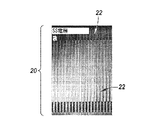
電解質は、フィラーとして官能化ポリ(エチレングリコール)(PEG)、リチウム塩、イオン液体、および酸化グラフェンの組合せを含むか、または(随意に)それらからなる。電解質16は、図2Aにおいて示すように、室温でペーストとして調製される。それは、このスラリーまたはペースト形態において3Dアーキテクチャーのチャネル22にて導入することができる。それは次に硬化されるか、またはさもなければ物質の固形状態に固くされる。
The electrolyte contains or (optionally) a combination of functionalized poly (ethylene glycol) (PEG), lithium salts, ionic liquids, and graphene oxide as fillers.
架橋後、組成物は、ペーストから伸縮性の独立フィルムとして機能することができる状態に変換するその意図された機械的特性を発現する。バッテリーにおいてチャネルの外側で、これは図2Bに見ることができる。 After cross-linking, the composition develops its intended mechanical properties of transforming the paste into a state capable of functioning as a stretchable independent film. Outside the channel in the battery, this can be seen in Figure 2B.
ポリマー電解質の調製プロセスおよび電極システムへのその組込みは、有機溶媒を使用せずに達成することができる。一旦目的の電極がモールドに組み立てられると、ポリマー電解質を組み込むことができる。 The process of preparing the polymer electrolyte and its incorporation into the electrode system can be achieved without the use of organic solvents. Once the electrode of interest is assembled in the mold, the polymer electrolyte can be incorporated.
1つの例では、すべての化合物は、約60℃またはそれよりも高い(約60℃以上とも言う)(例えば、最大値として約80℃までで、そこでは、随意に精巧に作られた会合された成分のアジド官能基が分解し始めるより下まで)で、混合物が均質になるまで一緒に混合される(すなわち、約60℃未満のポリ(エチレングリコール)の低融点を利用する)。次に、混合物を図1Cに見られる電極システム24の上部に注ぐ。
In one example, all compounds are at or above about 60 ° C (also referred to as about 60 ° C or higher) (eg, up to about 80 ° C, where optionally elaborately crafted associations. It is mixed together until the mixture is homogeneous (ie, taking advantage of the low melting point of poly (ethylene glycol) below about 60 ° C.) until the azide functional groups of the constituents begin to decompose). The mixture is then poured onto the top of the
その流動性のために、少なくとも約60℃の温度で、ポリマー電解質混合物は電極システムに注入することができる(is able infuse into)。このプロセスは、バキュームまたは不活性(例えば、希ガスまたはN2)雰囲気下で行うことができる。 Due to its fluidity, the polymer electrolyte mixture can be injected into the electrode system at a temperature of at least about 60 ° C. This process can be carried out in a vacuum or inert (eg, noble gas or N 2 ) atmosphere.
続いてポリマー電解質を硬化させる。紫外線(UV)光、炉またはオーブンの熱および/またはマイクロ波エネルギーによる硬化は、ポリマーの架橋および機械的強度の顕著な増加をもたらす。ポリマー電解質の機械的特性(例えば、可撓性、弾性および/または変形性)は、成分比を変動することによって最適化することができる。実例の化合物には、yモル比EO/Liおよびxモル比BMP/Liを有するPEOyLiTFSIxBMPTFSIが含まれ、式中、PEO=ポリ(エチレン)オキシド、LiTFSI=ビス(トリフルオロメチルスルホニル)リチウム塩およびBMPTFI(イオン液体)=1-ブチル-1-メチルピロリジニウムビス(トリフルオロメチルスルホニル)イミドであり、およびYは10から20まで、およびxは0から4まで変動することができる。x=0を伴い、ポリマー電解質フィルムは粘着性がなく、剛性で、および伸縮性ではない。図3に示される導電性について試験されたそのような化合物の例を以下のテーブルに示す: Subsequently, the polymer electrolyte is cured. Curing by ultraviolet (UV) light, furnace or oven heat and / or microwave energy results in a significant increase in polymer cross-linking and mechanical strength. The mechanical properties of the polymer electrolyte (eg, flexibility, elasticity and / or deformability) can be optimized by varying the component ratio. Examples of compounds include PEOyLiTFSIxBMPTFSI with y-molar ratio EO / Li and x-molar ratio BMP / Li, in the formula PEO = poly (ethylene) oxide, LiTFSI = bis (trifluoromethylsulfonyl) lithium salt and BMPTFI. (Ionic liquid) = 1-butyl-1-methylpyrrolidinium bis (trifluoromethylsulfonyl) imide, and Y can vary from 10 to 20 and x can vary from 0 to 4. With x = 0, the polymer electrolyte film is non-sticky, rigid, and non-stretchable. Examples of such compounds tested for conductivity shown in Figure 3 are shown in the table below:

すなわち、硬化の際、PEGの官能基は架橋を受け、その結果、機械的特性(上記のような)が顕著に増加する。異なる組合せの塩(例えば、上記のもの)および/またはイオン液体(例えば、1-エチル-3-メチルイミダゾリウムビス(トリフルオロメタンスルホニル)イミド(EMI-TFSI)、N-メチル,N-プロピルピペリジニウムビス(トリフルオロメタンスルホニル)イミド(MPP-TFSI)、N-ブチル,N-プロピルピロリジニウムビス(トリフルオロメタンスルホニル)イミド(BMP-TFSI)、N-ブチル,N-プロピルピロリジニウムトリス(ペンタフルオロエチル)トリフルオロホスファート(BMP-FAP)およびN-ブチル,N-プロピルピロリジニウムビス(フルオロスルホニル)イミド(BMP-FSI)および/またはここに参照することによりその全体において組み込まれる米国特許出願公開第(USPPN)20150380767号に記載されているようなもの)の組込みは、ポリマー電解質のイオン伝導性を著しく高める。グラフェンオキシド(GO)シートは、優れた機械的特性を有し、およびポリマー電解質の引張強さを増加させるPEGと強く相互作用する。さらに、GO酸素基はイオン輸送を促進し、およびイオン伝導性を改善する。したがって、この特定のポリマー電解質は、非常に良好な機械的特性および良好なイオン伝導性の双方を所有する。 That is, upon curing, the functional groups of PEG are crosslinked, resulting in a significant increase in mechanical properties (as described above). Different combinations of salts (eg, above) and / or ionic liquids (eg, 1-ethyl-3-methylimidazolium bis (trifluoromethanesulfonyl) imide (EMI-TFSI), N-methyl, N-propylpiperidi). Niumbis (trifluoromethanesulfonyl) imide (MPP-TFSI), N-butyl, N-propylpyrrolidiniumbis (trifluoromethanesulfonyl) imide (BMP-TFSI), N-butyl, N-propylpyrrolidinium tris (penta) Fluoroethyl) trifluorophosphate (BMP-FAP) and N-butyl, N-propylpyrrolidinium bis (fluorosulfonyl) imide (BMP-FSI) and / or US patents incorporated herein by reference in their entirety. Incorporation (as described in Application Publication No. (USPPN) 20150380767) significantly enhances the ionic conductivity of polymer electrolytes. Graphene oxide (GO) sheets have excellent mechanical properties and interact strongly with PEG, which increases the tensile strength of the polymer electrolyte. In addition, GO oxygen groups promote ion transport and improve ionic conductivity. Therefore, this particular polymer electrolyte possesses both very good mechanical properties and good ionic conductivity.
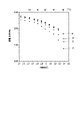
ポリマー電解質のいくつかの組成物のイオン伝導性の例(上記のテーブル1に示す例A-D)を、温度の関数として図3に示す。示されるように、1mS/cmに近いイオン伝導性は室温で達成することができ、それは固形電解質にとって高いと考えられる。比較のために、ガラスセラミック電解質は、10-5ないし10-4S/cmの範囲においてイオン伝導性を有し、およびPEOベースの電解質は、10-5S/cmの範囲において伝導性を有する。 Examples of ionic conductivity of some compositions of polymer electrolytes (Example AD shown in Table 1 above) are shown in FIG. 3 as a function of temperature. As shown, ionic conductivity close to 1 mS / cm can be achieved at room temperature, which is believed to be high for solid electrolytes. For comparison, glass-ceramic electrolytes have ionic conductivity in the range of 10 -5 to 10 -4 S / cm, and PEO-based electrolytes have conductivity in the range of 10 -5 S / cm. ..
さらに、導電性は、典型的な液状電解質、例えば、エチレンカルボナート/ジメチルカルボナートにおける慣習的な1Mリチウムヘキサフルオロホスファート(EC/DMC中1MのLiPF6)などのようなものより約1桁低いままである。選定されたバッテリーアーキテクチャーおよび随意のSi/S化学物質とともに、非常に良好な性能を有する二次電池である(例えば、以下に詳述するようである)。 In addition, conductivity is about an order of magnitude lower than that of typical liquid electrolytes, such as the conventional 1M lithium hexafluorophosphate in ethylene carbonate / dimethyl carbonate (1M LiPF6 in EC / DMC). Until now. A rechargeable battery with very good performance, along with the selected battery architecture and optional Si / S chemicals (eg, as detailed below).
3Dアーキテクチャーは、電解質を通して活物質(群)間の短いイオン輸送長さを可能にする。実例の距離(以下による)は、アノードからカソードへの迅速なイオン輸送をもたらし、および逆もまた同様である。導電性の異なる電解質(すなわち、対象ポリマー電解質を用いて1mS/cm、1MのLiPF6液状電解質を用いて10mS/cm)を有する様々なインターレース(組み合わせるとも言う)電極の「フィンガー」幅において構成された500μm高さのVACNTsを有する3D Si/Li2Sバッテリーアーキテクチャーを考え、以下の値をモデル化した: The 3D architecture allows for short ion transport lengths between active materials (groups) through the electrolyte. The example distance (according to:) results in rapid ion transport from the anode to the cathode, and vice versa. Consists of "finger" widths of various interlaced (also referred to as combined) electrodes with differently conductive electrolytes (ie, 1 mS / cm with the polymer electrolyte of interest, 10 mS / cm with the 1M LiPF6 liquid electrolyte). Considering a 3D Si / Li2S battery architecture with VACNTs with a height of 500 μm, the following values were modeled:


実施形態の第2のセット
A second set of embodiments
3D電極アーキテクチャーおよびそれらの製造のためのプロセスが(必ずしもそうとは限らないが)、上記の固形電解質に関連して使用するために企図される。電極配置はバッテリーを作成する際の重要な考慮事項の1つである。2Dジオメトリーを備えた目下のLi-イオンバッテリーは大キャパシティを達成するために大きなフットプリント領域を必要とし、それに対して、3Dバッテリーアーキテクチャーは面外寸法を使用する利益を有する。このことは、与えられたフットプリント領域内の電極材料の量を増加させることによって面積キャパシティ(areal capacity)を増加させることができる。また、より一層短いイオン拡散距離を有するより一層利用しやすい表面を可能にすることによって、電気化学的特性を改善することもできる。 The 3D electrode architecture and the process for their manufacture (but not necessarily) are intended for use in connection with the solid electrolytes described above. Electrode placement is one of the important considerations when making a battery. Current Li-ion batteries with 2D geometry require a large footprint area to achieve large capacity, whereas 3D battery architecture has the benefit of using out-of-plane dimensions. This can increase the areal capacity by increasing the amount of electrode material in a given footprint area. Also, electrochemical properties can be improved by allowing for a more accessible surface with a shorter ion diffusion distance.
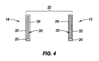
実例の電極アーキテクチャーを図4において示す。シリコン26およびイオウ28は、活性電極材料を提供することができる。VACNT構造30は、スキャフォールド(足場とも言う)および(随意の)グラフェンエンクロージャー(グラフェン封入とも言う)32をそれぞれ提供する。図1A-1Cにおいて示す構成で採用するとき、これにより、充電および放電サイクル中に、バッテリー化学物質が自由に膨張および収縮することが可能になる(例えば、シリコンおよびイオウ)。
An example electrode architecture is shown in Figure 4.
ここでの実施形態は、高アスペクト比の電極要素、例えば、図1A-1Cおよび4に示すものなどのようなものを用いた生産のための2つの新しい3Dバッテリー製造プロセスを含む。「高アスペクト比」によって、意味されるものは2および約25の間であり、そこでは、最大VACNTの高さが、約25から約200μmまでの与えられたフィンガーの幅を伴う約500μmであってよい。 Embodiments here include two new 3D battery manufacturing processes for production using high aspect ratio electrode elements such as those shown in FIGS. 1A-1C and 4. By "high aspect ratio" is meant between 2 and about 25, where the maximum VACNT height is about 500 μm with a given finger width from about 25 to about 200 μm. It's okay.
対象のプロセスは、各電極の分離し、および独立した調製を可能にする。これは、異なるアノードおよびカソード活物質を各VACNTアレイに組み込むことが異なる手法に関係するため、有利である。 The process of interest allows for the separation and independent preparation of each electrode. This is advantageous because incorporating different anode and cathode active materials into each VACNT array involves different techniques.
双方のプロセスにおいて、カソードおよびアノード構造は、電極が交互のアノードおよびカソードと互いにかみ合うことを可能にする特定の構造においてパターン形成される。この構成の例を図1A-1Cおよび5-7に示す。 In both processes, the cathode and anode structures are patterned in a particular structure that allows the electrodes to engage with the alternating anodes and cathodes. Examples of this configuration are shown in Figures 1A-1C and 5-7.
組み立てられるとき、電極は同じ平面内にある(随意に、それらの基材支持表面と共に)が、しかし、互いに接触することなく位置される。電極は、充放電サイクル中の容量変化によって誘発される応力および歪みに適応するために(すなわち、Si/S化学でも)、図1Cおよび4に示すように、それらの間に十分なチャネル空間またはギャップ22を有し、その一方、高い出力密度は、短い電子およびイオン輸送長さを、活物質において(典型的には100μm未満)および電解質において(典型的には100μm未満、および好ましくは約30μmまで下に)維持することによって達成され得る。
When assembled, the electrodes are in the same plane (optionally with their substrate supporting surfaces), but are positioned without contact with each other. The electrodes have sufficient channel space or sufficient channel space between them to adapt to the stresses and strains induced by capacitance changes during the charge / discharge cycle (ie, even in Si / S chemistry), as shown in Figures 1C and 4. It has a
これらの実施形態では、含まれる電流コレクタの形状は、カソードおよびアノードの双方の形状を決定する。製造プロセスは、電流コレクタを分離し、材料の単体からのそれらの機械加工によって開始することができる。非接触高速レーザーまたは放電機械加工(EDM)技術を用いて、正確な電極を作成することができる。あるいはまた、個々の(対して、対形成された)部分を機械加工し得る。 In these embodiments, the shape of the included current collector determines the shape of both the cathode and the anode. The manufacturing process can be started by separating the current collectors and machining them from a single piece of material. Non-contact high speed lasers or discharge machining (EDM) techniques can be used to create accurate electrodes. Alternatively, individual (as opposed to paired) parts may be machined.
図5に示すように、組立てバッテリー構造において集電体(群)20として、ニッケル(Ni)および触媒(示していない)で被覆されたステンレス鋼(SS)を使用することができる。この例では、各集電体「フィンガー」要素は、長さ1.44cmおよび幅335μmであり、および約30μmのインターリーブ(混ぜ入れるとも言う)部分の間のチャネル22のために構成される。
As shown in FIG. 5, stainless steel (SS) coated with nickel (Ni) and a catalyst (not shown) can be used as the current collector (group) 20 in the assembled battery structure. In this example, each current collector "finger" element is 1.44 cm long and 335 μm wide, and is configured for
特に、ニッケル(Ni)は、触媒特性またはその他の点で望ましい場合、切断の前または後にステンレス鋼上に(よく知られる微細加工技術、例えば、リソグラフィー、物理蒸着(PVD)または電気メッキなどのようなものを用いて)堆積させることができる。触媒の添加により、VACNT足場(図5において示していない)は次いで、パターン形成された電流コレクタ上にCVD堆積技術によって直接成長させられる。SiおよびS(またはLi2S)は、各電極上のVACNT足場中に別々に組み込まれてもよい。次に、Si/VACNTおよびS/VACNT(またはLi2S/VACNT)をラップまたはコーティングするために、グラフェン(またはグラフェンおよびPLA複合体)を使用することができる。特に、VACNT足場の使用は、それらの内部電気抵抗をエスカレートさせることや、または出力密度に影響を及ぼすことなく、シリコンおよびイオウ活物質の非常に厚いフィルム(膜とも言う)(例えば、数mmまで)の使用を可能にする。 In particular, nickel (Ni), if desired in terms of catalytic properties or other aspects, on stainless steel before or after cutting (such as well-known microfabrication techniques such as lithography, physical vapor deposition (PVD) or electroplating, etc. Can be deposited). With the addition of the catalyst, the VACNT scaffold (not shown in FIG. 5) is then grown directly on the patterned current collector by CVD deposition techniques. Si and S (or Li2S) may be incorporated separately into the VACNT scaffold on each electrode. Graphene (or graphene and PLA complex) can then be used to wrap or coat Si / VACNT and S / VACNT (or Li2S / VACNT). In particular, the use of VACNT scaffolds is a very thick film (also called a film) of silicon and sulfur active material (eg, up to a few mm) without escalating their internal electrical resistance or affecting the output density. ) Can be used.
アセンブリ(集合とも言う)の際、電流コレクタ部分の間の電気的絶縁のために、微細構造ポリマー要素(群)を使用することができる。フォトリソグラフィー技術は、エポキシベースのフォトレジストを使用して微細構造の「モールド」を製造するために用いることができる(例えば、SU-8/2002/2100またはSU-8/2002/2150)。この要素は、アノードおよびカソードを分離するために使用される(例えば、上述の30μmのチャネルまたはギャップの例に適合する)。フォトリソグラフィープロセスは、フォトレジストパターニングのために使用され、概して、スピンコーティング、ソフトベーク、近UV曝露、現像、およびポストベークを含む。 During assembly (also referred to as assembly), ultrastructure polymer elements (groups) can be used for electrical insulation between current collector moieties. Photolithography techniques can be used to make microstructured "molds" using epoxy-based photoresists (eg, SU-8 / 2002/2100 or SU-8 / 2002/2150). This element is used to separate the anode and cathode (eg, fits the 30 μm channel or gap example described above). Photolithography processes are used for photoresist patterning and generally include spin coating, soft bake, near UV exposure, development, and post bake.
SU-8微細構造は、ガラスまたは酸化ケイ素基材または任意のタイプの非導電性基材上に形成し得る。基材への良好な付着および全体的な高アスペクト比の微細構造(例えば、約5ないし約25のオーダーで)のために、SU-8/2002をベース層として使用し、続いてSU-8 2100または2150を適用することができる。 SU-8 microstructures can be formed on glass or silicon oxide substrates or any type of non-conductive substrate. SU-8 / 2002 was used as the base layer for good adhesion to the substrate and microstructure with an overall high aspect ratio (eg, on the order of about 5 to about 25), followed by SU-8. 2100 or 2150 can be applied.
図6は、リソグラフィー技術によって作成された酸化ケイ素ウェハ上のSU-8微細構造素子40を示す。ギャップ22に収まる各「ライン(線とも言う)」の幅は10μmであり、および全体の厚さは約250μmである。この厚さは、約25μmないし約250μmの電流コレクタ20の厚さと協調する。言い換えれば、図7に示すように位置され、または据え付けられたものである場合、微細構造要素または要素群は、典型的にはステンレス鋼電流コレクタの厚さと一致するように、電気的短絡から電極基材または電流コレクタを絶縁する。さらに、ポリマー微細構造または微細構造要素40は、電極の基部を単独に分離する。それらの相互(平面)表面上、電解質はVACNTs30および関連する活物質26、28および/またはエンケーシング(包囲体とも言う)32を分離する。SU-8材料要素40の例の電気抵抗は2.8×10 16Ω.cmである。
FIG. 6 shows SU-8
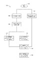
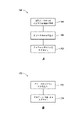
図8は、上記に関連するプロセスを詳細に示す。プロセス100は102にて開始される。作用の一つのラインに沿って、104にて、上記のモールドの微細構造要素(群)が参照される。 FIG. 8 details the process related to the above. Process 100 starts at 102. Along one line of action, at 104, the microstructural elements (groups) of the above mold are referenced.
他のラインに沿って、電流コレクタ部分が106にて、随意に、上述したように切断される。108にて、VACNTsは基材または電流コレクタ電極部分上で成長する。 Along the other line, the current collector portion is optionally cut at 106 as described above. At 108, VACNTs grow on the substrate or current collector electrode portion.
アノード「側」またはバッテリーの一部分について、SiをCNT足場において110で組み込むことができる。カソード側用に、そのCNTsにおいて112でLi2Sを組み込むことができる。 Si can be incorporated at 110 on the CNT scaffold for the anode "side" or part of the battery. For the cathode side, Li 2 S can be incorporated at 112 in its CNTs.
114では、アノードおよびカソードは、微細構造「モールド」要素(群)と一緒に組み立てられる。116にて、このサブアセンブリは、上述のように(または他の方法で)ポリマー電解質で満たされ、および/またはそこに封入される。例示していないが、次いでハウジングおよび様々な電気的接続を(例えば、図1Aおよび1Bに関連して例示するように)適用することができる。 At 114, the anode and cathode are assembled together with a microstructured "mold" element (s). At 116, this subassembly is filled with (or otherwise) the polymer electrolyte as described above and / or encapsulated therein. Although not illustrated, housings and various electrical connections can then be applied (eg, as illustrated in connection with FIGS. 1A and 1B).
このセット(設定とも言う)の実施形態の別の例では、製造プロセスは、レーザー切断または他の方法によって、規定されたパターン(例えば、前述の「櫛」または「ブラシ」形状)を用いて、セラミック(例えば、Al2O3)基材を切断することを包含する。そのような取り組みは、互いに挿入されるセラミック基材片50、52と共に図9Aに例示される。図9Bは、ニッケル電流コレクタ20の材料堆積後のセラミック基材の2つの部分を示す。セラミックまたは非導電性ポリマー、例えば、ポリジメチルシロキサン(PDMS)などのようなものを基材として使用することは、次の:1)寸法安定性、2)切断からのゆがみに対する抵抗性、3)より一層微細な特長分解能(feature resolution)を達成する能力および/または4)熱影響ゾーンがないことを含む潜在的な利益を提供する。
In another example of an embodiment of this set (also referred to as a setting), the manufacturing process uses a defined pattern (eg, the "comb" or "brush" shape described above) by laser cutting or other methods. Includes cutting ceramic (eg, Al 2 O 3 ) substrates. Such efforts are illustrated in Figure 9A, along with
再び、VACNT足場は次に、CVD堆積技術によって、パターン化された電流コレクタ(群)上に成長させることができる。SiおよびLi2Sはまた、切断された電極の各側にてVACNT足場中に個別に組み込むこともできる。次に、グラフェンはVACNTsをラップまたはコート(cote)するために用いられ得る。最後に、上記のように、電極(カソードおよびアノード)は互いに挿入される。 Again, the VACNT scaffold can then be grown on a patterned current collector (s) by CVD deposition technology. Si and Li 2 S can also be individually integrated into the VACNT scaffold on each side of the truncated electrode. Graphene can then be used to wrap or coat VACNTs. Finally, as mentioned above, the electrodes (cathode and anode) are inserted into each other.
より一層詳細には、図10で、一旦プロセス120が122にて開始すると、それは124にてセラミック基材を切断することを含む。基材は次いで、金属(例えば、ニッケル)を用いてコーティングまたはパターン化される。128において、VACNTsは、パターン化された金属上に成長され、それはセラミック基材にわたり電流コレクタとして働く。
More specifically, in FIG. 10, once
上記のように、活物質が、VACNTsにおいて、130および132にて組み込まれる。随意に、134にて、負荷されたVACNTsは、グラフェンフィルムにおいて336および138にて封入されてもよい。 As mentioned above, the active material is incorporated in VACNTs at 130 and 132. Optionally, the VACNTs loaded at 134 may be encapsulated at 336 and 138 in the graphene film.
アノードおよびカソードは次いで、140で(微細構造モールドの分離を必要とせずに)組み立てられ、および142で(随意に)ポリマー電解質で充填される。上記のようにして、ポリマー電解質を次に硬化させることができる。さらに、電極は、上記のようにカプセル封入されてもよく、および/または他の最終的なバッテリー製造行為またはステップ、例えば、構造を包むこと、等などのようなものが完了してもよい。
実施形態の第3のセット
The anode and cathode are then assembled at 140 (without the need for separation of the microstructure mold) and at 142 (optionally) filled with a polymeric electrolyte. As described above, the polymer electrolyte can then be cured. In addition, the electrodes may be encapsulated as described above and / or other final battery manufacturing actions or steps, such as wrapping the structure, etc., may be completed.
Third set of embodiments
第3のセットの実施形態は、ポリ(エチレン)オキシドビス(アジド)(PEO-N3)ポリマーを用いてシリコンアノード上に予め形成された安定なSEIを生成することを含む(例えば、図4においてアノード14上のコーティング32におけるようである)。そのようにして製造されたシリコン表面26上の薄い(例えば、約2nmおよび100nmの間の)保護層は、高性能で、および良好なサイクル寿命(good cyclability)のリチウムイオンバッテリーに寄与する(例えば、理論値の80%のキャパシティを維持することが10サイクルを超えて得られた)。
A third set of embodiments comprises using a poly (ethylene) oxide bis (azido) (PEO-N3) polymer to produce a stable SEI preformed on a silicon anode (eg, the anode in FIG. 4). 14 as in coating 32 on). A thin protective layer (eg, between about 2 nm and 100 nm) on the
適用(例えば、以下にさらに記載するように)、および硬化させると、ポリマーのアジド官能基は高度に反応性のニトレン(ナイトレンとも言う)ラジカルに変換され、ポリマーの架橋を、およびその機械的特性の著しい増加をもたらす。これらの機械的特性は、ポリマーマトリクス中にグラフェン、イオン液体、または有機低分子の小量(例えば、全体組成の約1ないし約2重量%)を組み込むことによって増強することができる。したがって、ポリマー層は、シリコン電極の容量変化に適合するのに役立つことができる(すなわち、それは電極の応力および歪みを緩衝する)。 Upon application (eg, as further described below) and curing, the azide functional groups of the polymer are converted to highly reactive nitrene (also called nitrene) radicals, cross-linking the polymer and its mechanical properties. Brings a significant increase in. These mechanical properties can be enhanced by incorporating small amounts of graphene, ionic liquids, or small organic molecules (eg, about 1 to about 2% by weight of the total composition) into the polymer matrix. Therefore, the polymer layer can help adapt to the capacitance changes of the silicon electrode (ie, it cushions the stress and strain of the electrode).
アジド基の別の重要な特長は、それらがUV照射を受けるとき、シリコン表面に結合するそれらの能力である。この特長は、シリコン表面を保護し、および各サイクルにおいて電解質のさらなる分解を防止する。一緒になって、これらの特長または態様は、シリコンアノードのサイクリング(循環とも言う)中に安定なSEIを形成するポリマー層を提供する。本対象のポリマーはまた、高いリチウムイオン伝導性(例えば、約1mS/cm)を提供する。特に、ポリ(エチレン)オキシドベースのポリマーは、それらのよく知られる高いイオン伝導性のために、固形状態のリチウムイオンバッテリーにおいて広く使用される。したがって、ポリマー層はシリコン表面を保護する一方、それはまた、アノード材料への、およびそれからのリチウムイオン輸送を可能にする。 Another important feature of azide groups is their ability to bind to the silicon surface when they are exposed to UV irradiation. This feature protects the silicon surface and prevents further decomposition of the electrolyte at each cycle. Together, these features or embodiments provide a polymer layer that forms a stable SEI during cycling (also referred to as circulation) of the silicon anode. The polymer of interest also provides high lithium ion conductivity (eg, about 1 mS / cm). In particular, poly (ethylene) oxide-based polymers are widely used in solid lithium-ion batteries due to their well-known high ionic conductivity. Thus, while the polymer layer protects the silicon surface, it also allows lithium ion transport to and from the anode material.
高温(例えば、約80℃以下)を適用することなく、図11において例示するように、ポリマー層を形成するためのプロセス150を達成し得る。具体的に、152において、PEO-N3を有機溶液にて溶解する。次いで、154において、シリコンアノードをPEO-N3溶液中に浸漬被覆する。156にて、薄い(例えば、約10μmないし100μm、より一層好ましくは10μmないし20μmの)ポリマー層が続いて硬化される。UV光、対流熱(例えば、約250℃にて)またはマイクロ波を硬化のために使用することができる。
実施形態の第4のセット
The
Fourth set of embodiments
さらに別のセットの実施形態では、いわゆる「ポリスルフィドトラップ」がリチウムイオウバッテリー用に生産される。実例のリチウムイオウセルは、リチウム含有アノード、カソードおよびリチウム含有アノードとイオウ含有カソードとの間のセパレータを含む。活物質の損失を防止し、およびポリスルフィドのアノード側への移動を停止するために、イオウ活物質28の電極(カソード)12を、グラフェンおよび熱可塑性ポリマー(例えば、ポリ(乳酸)(PLA))複合体層32を用いて図4におけるようにカバーする(少なくとも部分的に)。グラフェンおよびPLAの複合体層は効果的なリチウムポリスルフィドトラップを示し、さもなければバッテリー内で生じるであろうシャトル機構(すなわち、電解質におけるリチウムポリスルフィドの溶解)を防止する。イオウバッテリーにおける乏しいサイクル寿命、低い比キャパシティおよび低いエネルギー効率をもたらす以前の問題は、イオウと、グラフェンおよびPLA複合体で被覆またはカバーされたVACNTsとの複合体を含むカソードにより対処される。VACNTsは、Sベースのカソードの導電性を高めるために採用されるが、その一方、グラフェンおよびPLA複合体は、ポリスルフィドを助け、またはその電解質への溶解を全体で防止し、およびグラフェンおよびPLAのエンクロージャー内のイオウ粒子の破壊を最小にする。別な方法で述べると、グラフェンおよびPLAは、グラフェンシートの柔軟な構造のために、ポリスルフィドにとって理想的なトラップである。同様に、グラフェンシートは、剛性および強度において改善につながるPLA鎖閉じ込め効果に寄与する可能性がある。
In yet another set of embodiments, so-called "polysulfide traps" are produced for lithium sulfur batteries. An exemplary lithium sulfur cell comprises a lithium-containing anode, a cathode and a separator between the lithium-containing anode and the sulfur-containing cathode. To prevent the loss of the active material and to stop the transfer of polysulfide to the anode side, the electrode (cathode) 12 of the sulfur
充放電サイクル中、グラフェンおよびPLA複合体のエンクロージャーは、電解質と、VACNTsにおいて形成されるポリスルフィドとの間の直接接触を防止する。このようにして、電解質中へのポリスルフィドの溶解は(上述のように)回避され、その一方で同時に、電気化学反応が起こることを可能にすることができる。この活性は、最終的にバッテリーサイクル寿命を改善し、全体のキャパシティを改善し、および図12においてG/PLAトラップ160を伴い、対して158では伴わないデータに見られるように、S-VACNTのキャパシティにおいてフェーディング(減退とも言う)を最小限にする。明らかに、著しくより一層高い初期キャパシティおよび全体のキャパシティは観察されるが、G/PLAトラップが適用されるとき、10サイクル後に見てわかるほどの減衰は観察されない。さらに、グラフェンエンクロージャーはまた、VACNTsの内部抵抗も低減し、最終的にはバッテリー効率を全体的に向上させる。
During the charge / discharge cycle, the graphene and PLA complex enclosure prevents direct contact between the electrolyte and the polysulfides formed in the VACNTs. In this way, dissolution of the polysulfide in the electrolyte can be avoided (as described above), while at the same time allowing an electrochemical reaction to occur. This activity ultimately improves battery cycle life, improves overall capacity, and S-VACNTs, as seen in the data with G /
図13Aは、そのようなカソード調製のためのプロセス162を例示する。164で、溶融イオウおよびイオウ含有溶液が調製される。それらは166で、上からの溶融、およびVACNTの空所中への流れによってイオウを注入し、その一方で、電解質が通過できるように被覆されたCNTsの間にいくらかの空間を可能にする)。イオウは炭素と非常に良好な親和性を有するので、CNTは容易に被覆され、各個々のCNTを被覆することが可能にされる。好首尾なイオウ注入プロセスは、VACNT構造の約300%ないし約350重量%(またはイオウとVACNTとの比約60%)の間の変化をもたらす。一旦VACNT足場がイオウによって注入されると、グラフェンおよびPLA複合体は168にてVACNTsを(浸漬、スピンコーティングまたは他の方法を介して)カプセル化する。
FIG. 13A illustrates
グラフェンおよびPLA溶液の異なる濃度は、典型的には、Siの1%ないし10重量%を有するG/PLAコーティングを得る目的で、グラフェンおよびPLAペレットまたはワイヤを塩素化溶媒中に溶解することによって得られる。グラフェンおよびPLA溶液は、スピンコーティング、ドロップキャスティングまたはスプレーコーティング法によってVACNT/S電極上に堆積される。 Different concentrations of graphene and PLA solutions are typically obtained by dissolving graphene and PLA pellets or wires in a chlorinated solvent for the purpose of obtaining a G / PLA coating with 1% to 10% by weight of Si. Be done. Graphene and PLA solutions are deposited on the VACNT / S electrode by spin coating, drop casting or spray coating.
同じ方法はバッテリーアノードの調製において用いることができる。そのような実施形態では、図4に関して説明したアノード14およびカソード12のそれぞれのためのコーティング32は、グラフェンおよびPLA複合体を含む。1つの特定の実例の実施形態では、そのコーティング32は、グラフェンおよびPLA複合体だけを含み、そして他の物質は含まない。Si-VACNTアノードをグラフェンおよびPLAとハイブリッド化することは、非常に大きな容量変化による構造的損傷を回避しながら、Siの高い理論キャパシティを利用するための解法を提供する。
The same method can be used in the preparation of battery anodes. In such an embodiment, the
そのようなコーティングは、上記のごとく形成された安定なSEI層にわたり適用することができる。この場合を除いて、図13Bのプロセス170において、CVD法または別の技術によって、シリコーン(Silicone)がアノードに、172にて組み込まれる。次に、Si-VACNTカソードは、グラフェンおよびPLA複合体で、174にて封入される。
実施形態のバリエーション
Such a coating can be applied over the stable SEI layer formed as described above. Except for this case, in
Variations of embodiments
対象の方法は、使用および/または製造の方法を含め、論理的に可能な事象の任意の順序だけでなく、暗唱された事象の任意の順序で遂行されてもよい。さらに、ある範囲の値が提供される場合、その範囲の上限と下限との間のあらゆる介在値および記載された範囲において任意の他の記載または介在値が本発明内に包含されることが理解される。また、記載された創意に富む実施形態または変形の任意の随意の特長は、ここに記載される任意の1以上の特長と、無関係に、または組み合わされて説明され、および請求され得ることが企図される。 The method of interest may be performed in any order of the implied events, as well as in any order of logically possible events, including methods of use and / or manufacture. Further, it is understood that if a range of values is provided, any intervening value between the upper and lower bounds of the range and any other description or intervening value within the stated range is included within the invention. Will be done. It is also contemplated that any voluntary features of the creative embodiments or variants described may be described and claimed independently or in combination with any one or more features described herein. Will be done.
本発明を、いくつかの例を参照し、随意に様々な特長を組み込んで記載したが、本発明は、本発明の各変形に関して企図されるように、記載され、または示されたものに制限されるものではない。本発明の真の精神および範囲から離れることなく、記載された本発明に対して様々な変化がなされてもよく、および等価なもの(ここに暗唱されているか、またはいくらか簡潔にするために含まれていないものかにかかわらず)を置換することができる。 Although the present invention has been described with reference to some examples and optionally incorporating various features, the invention is limited to those described or shown as intended for each variation of the invention. It is not something that will be done. Various changes may be made to the invention described, without departing from the true spirit and scope of the invention, and equivalents (recited herein or included for some brevity). (Whether it is not or not) can be replaced.
単数品目への言及には、複数の同じ品目が存在する可能性を含む。より一層具体的には、ここに、および添付の請求の範囲で使用されるように、単数形「a」、「an」、「said」および「the」は、特に別なように明記しない限り、複数の指示対象を含む。換言すれば、これらの物品を使用することにより、上記の明細ならびに下記の請求の範囲における対象項目の「少なくとも1つ」が考慮される。 References to a single item include the possibility of multiple identical items. More specifically, as used herein and in the appended claims, the singular forms "a", "an", "said" and "the" are unless otherwise stated. , Includes multiple referents. In other words, by using these articles, "at least one" of the above items as well as the subject matter in the claims below is taken into account.
同様に、請求の範囲において用語「含む」の使用は、任意の追加の要素の包含--与えられる数の要素が請求項に列挙されているかどうかにかかわらず、または請求の範囲に説明された要素の性質を転換すると見なされ得る特長の付加を含めることを可能にするものでなければならない。ここに特に規定される場合を除き、ここに使用されるすべての技術的および科学的用語は、クレームの妥当性を維持しながら、普通に理解される意味で可能な限り広く与えられるべきである。いずれの場合にも、ここに記載された異なる創意に富む実施形態または態様の幅は、提供された例および/または対象の明細に対してではなく、むしろ発行された請求項の言語の範囲によってだけ制限される。 Similarly, the use of the term "contains" in the claims is the inclusion of any additional elements--whether or not a given number of elements are listed in the claims, or as described in the claims. It must be able to include the addition of features that can be considered to transform the nature of the element. Unless otherwise specified herein, all technical and scientific terms used herein should be given as broadly as possible in a commonly understood sense, while maintaining the validity of the claims. .. In any case, the breadth of the different creative embodiments or embodiments described herein is not with respect to the examples provided and / or the subject matter, but rather with the scope of the claimed language issued. Only limited.
Claims (7)
アノード活物質を組み込むアノードカーボンナノチューブが支持される第1の集電体を含むアノードを形成すること;
カソード活物質を組み込むカソードカーボンナノチューブが支持される第2の集電体を含むカソードを形成すること;
前記第1の集電体および第2の集電体の間に密着するように設けられる固形ポリマー絶縁体を形成すること;および
前記第1の集電体、第2の集電体および固形ポリマー絶縁体を同一平面内にぴったりと合った関係に組み立てることであって、ここで、前記固形ポリマー絶縁体は、前記第1の集電体および第2の集電体を分離し且つ該第1の集電体および第2の集電体が電気的に短絡するのを防止するように構成される、こと
を含む、方法。 In manufacturing electrochemical cells
Forming an anode containing a first current collector in which the anode carbon nanotubes incorporating the anode active material are supported;
Forming a cathode containing a second current collector in which the cathode carbon nanotubes incorporating the cathode active material are supported;
Forming a solid polymer insulator provided in close contact between the first and second current collectors ; and
The first current collector , the second current collector, and the solid polymer insulator are assembled in an in-plane so-like relationship, wherein the solid polymer insulator is the first one. A method comprising separating a current collector and a second current collector and preventing the first and second current collectors from being electrically short-circuited .
The method of claim 1, wherein the solid polymer insulator is attached within a gap of 30 μm between the portions of the first and second current collectors .
Priority Applications (1)
| Application Number | Priority Date | Filing Date | Title |
|---|---|---|---|
| JP2022041260A JP2022088459A (en) | 2016-01-22 | 2022-03-16 | Vertical carbon nanotube and lithium ion battery chemistry |
Applications Claiming Priority (9)
| Application Number | Priority Date | Filing Date | Title |
|---|---|---|---|
| US201662286075P | 2016-01-22 | 2016-01-22 | |
| US201662286083P | 2016-01-22 | 2016-01-22 | |
| US62/286,075 | 2016-01-22 | ||
| US62/286,083 | 2016-01-22 | ||
| US201662287497P | 2016-01-27 | 2016-01-27 | |
| US62/287,497 | 2016-01-27 | ||
| US201662308740P | 2016-03-15 | 2016-03-15 | |
| US62/308,740 | 2016-03-15 | ||
| PCT/US2017/014359 WO2017127694A1 (en) | 2016-01-22 | 2017-01-20 | Vertical carbon nanotube and lithium ion battery chemistries |
Related Child Applications (1)
| Application Number | Title | Priority Date | Filing Date |
|---|---|---|---|
| JP2022041260A Division JP2022088459A (en) | 2016-01-22 | 2022-03-16 | Vertical carbon nanotube and lithium ion battery chemistry |
Publications (3)
| Publication Number | Publication Date |
|---|---|
| JP2019503554A JP2019503554A (en) | 2019-02-07 |
| JP2019503554A5 JP2019503554A5 (en) | 2020-02-13 |
| JP7043400B2 true JP7043400B2 (en) | 2022-03-29 |
Family
ID=59360886
Family Applications (2)
| Application Number | Title | Priority Date | Filing Date |
|---|---|---|---|
| JP2018525660A Active JP7043400B2 (en) | 2016-01-22 | 2017-01-20 | Chemistry, Articles, Architecture and Manufacturing of Vertical Carbon Nanotubes and Lithium Ion Batteries |
| JP2022041260A Pending JP2022088459A (en) | 2016-01-22 | 2022-03-16 | Vertical carbon nanotube and lithium ion battery chemistry |
Family Applications After (1)
| Application Number | Title | Priority Date | Filing Date |
|---|---|---|---|
| JP2022041260A Pending JP2022088459A (en) | 2016-01-22 | 2022-03-16 | Vertical carbon nanotube and lithium ion battery chemistry |
Country Status (9)
| Country | Link |
|---|---|
| US (2) | US11056712B2 (en) |
| EP (1) | EP3405990A4 (en) |
| JP (2) | JP7043400B2 (en) |
| KR (1) | KR20180103047A (en) |
| CN (1) | CN108475812A (en) |
| BR (1) | BR112018014921A2 (en) |
| CA (1) | CA3005768A1 (en) |
| MX (1) | MX2018006316A (en) |
| WO (1) | WO2017127694A1 (en) |
Families Citing this family (10)
| Publication number | Priority date | Publication date | Assignee | Title |
|---|---|---|---|---|
| US10950901B2 (en) * | 2017-03-31 | 2021-03-16 | Toyota Motor Europe | System and method for charge protection of a lithium-ion battery |
| JP7298732B2 (en) * | 2017-08-25 | 2023-06-27 | 株式会社三洋物産 | game machine |
| JP7298730B2 (en) * | 2017-11-15 | 2023-06-27 | 株式会社三洋物産 | game machine |
| JP7298731B2 (en) * | 2017-11-15 | 2023-06-27 | 株式会社三洋物産 | game machine |
| US10833436B2 (en) * | 2017-12-24 | 2020-11-10 | International Business Machines Corporation | Interdigitated power connector |
| EP3594179A1 (en) | 2018-07-10 | 2020-01-15 | Nederlandse Organisatie voor toegepast- natuurwetenschappelijk onderzoek TNO | 3d-scaffold comprising a substrate and carbon nanotubes |
| US11456483B2 (en) | 2019-03-04 | 2022-09-27 | The Mitre Corporation | Carbon fiber battery electrodes with ionic liquid and gel electrolytes |
| US20210194055A1 (en) * | 2019-12-20 | 2021-06-24 | Enevate Corporation | Solid-state polymer electrolyte for use in production of all-solid-state alkali-ion batteries |
| CN113193228B (en) * | 2021-04-27 | 2022-08-23 | 山东玉皇新能源科技有限公司 | Crosslinked solid electrolyte and preparation method and application thereof |
| CN115036546B (en) * | 2022-06-30 | 2024-01-26 | 广东墨睿科技有限公司 | Wearable graphene-based enzyme biofuel cell and preparation method and application thereof |
Citations (6)
| Publication number | Priority date | Publication date | Assignee | Title |
|---|---|---|---|---|
| JP2006147210A (en) | 2004-11-17 | 2006-06-08 | Hitachi Ltd | Secondary battery and production method therefor |
| JP2012119236A (en) | 2010-12-02 | 2012-06-21 | Dainippon Screen Mfg Co Ltd | Battery manufacturing method, battery, motor vehicle, rf-id tag, and electronic device |
| CN102891335A (en) | 2012-10-11 | 2013-01-23 | 同济大学 | Preparation method of full-solid-state nano composite polymer electrolyte |
| JP2013521629A (en) | 2010-03-11 | 2013-06-10 | ハリス コーポレイション | Double layer solid battery |
| WO2014203965A1 (en) | 2013-06-21 | 2014-12-24 | 東京応化工業株式会社 | Nonaqueous secondary battery and method for manufacturing same |
| US20150010788A1 (en) | 2013-07-03 | 2015-01-08 | California Institute Of Technology | Carbon Nanotubes - Graphene Hybrid Structures for Separator Free Silicon - Sulfur Batteries |
Family Cites Families (16)
| Publication number | Priority date | Publication date | Assignee | Title |
|---|---|---|---|---|
| JPH10265674A (en) | 1997-03-25 | 1998-10-06 | Mitsubishi Chem Corp | Polymer compound composite material and its production |
| CN1901255B (en) * | 2000-10-20 | 2013-11-06 | 麻省理工学院 | Reticulated and controlled porosity battery structures |
| JP3565777B2 (en) * | 2000-10-25 | 2004-09-15 | Necトーキン株式会社 | Polymer battery |
| KR101178643B1 (en) * | 2001-07-27 | 2012-09-07 | 에이일이삼 시스템즈 인코포레이티드 | Battery structures, self-organizing structures and related methods |
| JP4352016B2 (en) * | 2005-03-18 | 2009-10-28 | 株式会社東芝 | Inorganic solid electrolyte battery and method for producing inorganic solid electrolyte battery |
| JP5115920B2 (en) * | 2006-02-24 | 2013-01-09 | 日本碍子株式会社 | All solid battery |
| CN101663788B (en) * | 2007-02-16 | 2012-11-14 | 那米克斯公司 | Lithium ion secondary battery and process for manufacturing the same |
| WO2009120872A2 (en) * | 2008-03-26 | 2009-10-01 | Ada Technologies, Inc. | High performance batteries with carbon nanomaterials and ionic liquids |
| JP5508833B2 (en) * | 2009-12-21 | 2014-06-04 | ナミックス株式会社 | Lithium ion secondary battery |
| US20140093769A1 (en) | 2011-05-19 | 2014-04-03 | Northeastern University | Carbon Nanotube-Based Electrode and Rechargeable Battery |
| TWI453972B (en) * | 2011-12-15 | 2014-09-21 | Ind Tech Res Inst | Solid polymer electrolyte composition |
| KR101381932B1 (en) * | 2012-03-08 | 2014-04-07 | 엘에스엠트론 주식회사 | Current collector for lithium secondary battery and method for producing the same |
| KR101606898B1 (en) * | 2014-04-03 | 2016-03-28 | 숭실대학교산학협력단 | Flexible secondary lithium battery |
| CN106660977B (en) * | 2014-05-27 | 2020-09-01 | 金泰克斯公司 | Electrochemical energy storage device |
| KR102452944B1 (en) * | 2015-05-12 | 2022-10-11 | 삼성전자주식회사 | Electrolyte composite, and negative electrode and lithium second battery including the electrolyte composite |
| CN105218992B (en) * | 2015-07-08 | 2017-08-29 | 苏州高通新材料科技有限公司 | sulfonated graphene metal salt solid polymer electrolyte and its preparation method and application |
-
2017
- 2017-01-20 MX MX2018006316A patent/MX2018006316A/en unknown
- 2017-01-20 WO PCT/US2017/014359 patent/WO2017127694A1/en active Application Filing
- 2017-01-20 CN CN201780007175.7A patent/CN108475812A/en active Pending
- 2017-01-20 BR BR112018014921A patent/BR112018014921A2/en not_active Application Discontinuation
- 2017-01-20 EP EP17742020.5A patent/EP3405990A4/en active Pending
- 2017-01-20 JP JP2018525660A patent/JP7043400B2/en active Active
- 2017-01-20 CA CA3005768A patent/CA3005768A1/en active Pending
- 2017-01-20 US US15/411,544 patent/US11056712B2/en active Active
- 2017-01-20 KR KR1020187016919A patent/KR20180103047A/en not_active Application Discontinuation
-
2021
- 2021-06-29 US US17/361,993 patent/US20220123356A1/en not_active Abandoned
-
2022
- 2022-03-16 JP JP2022041260A patent/JP2022088459A/en active Pending
Patent Citations (6)
| Publication number | Priority date | Publication date | Assignee | Title |
|---|---|---|---|---|
| JP2006147210A (en) | 2004-11-17 | 2006-06-08 | Hitachi Ltd | Secondary battery and production method therefor |
| JP2013521629A (en) | 2010-03-11 | 2013-06-10 | ハリス コーポレイション | Double layer solid battery |
| JP2012119236A (en) | 2010-12-02 | 2012-06-21 | Dainippon Screen Mfg Co Ltd | Battery manufacturing method, battery, motor vehicle, rf-id tag, and electronic device |
| CN102891335A (en) | 2012-10-11 | 2013-01-23 | 同济大学 | Preparation method of full-solid-state nano composite polymer electrolyte |
| WO2014203965A1 (en) | 2013-06-21 | 2014-12-24 | 東京応化工業株式会社 | Nonaqueous secondary battery and method for manufacturing same |
| US20150010788A1 (en) | 2013-07-03 | 2015-01-08 | California Institute Of Technology | Carbon Nanotubes - Graphene Hybrid Structures for Separator Free Silicon - Sulfur Batteries |
Also Published As
| Publication number | Publication date |
|---|---|
| MX2018006316A (en) | 2018-09-18 |
| CN108475812A (en) | 2018-08-31 |
| CA3005768A1 (en) | 2017-07-27 |
| US11056712B2 (en) | 2021-07-06 |
| JP2019503554A (en) | 2019-02-07 |
| EP3405990A4 (en) | 2020-02-19 |
| KR20180103047A (en) | 2018-09-18 |
| JP2022088459A (en) | 2022-06-14 |
| US20170214083A1 (en) | 2017-07-27 |
| BR112018014921A2 (en) | 2018-12-18 |
| WO2017127694A1 (en) | 2017-07-27 |
| EP3405990A1 (en) | 2018-11-28 |
| US20220123356A1 (en) | 2022-04-21 |
Similar Documents
| Publication | Publication Date | Title |
|---|---|---|
| JP7043400B2 (en) | Chemistry, Articles, Architecture and Manufacturing of Vertical Carbon Nanotubes and Lithium Ion Batteries | |
| Nanda et al. | Anode‐free full cells: a pathway to high‐energy density lithium‐metal batteries | |
| Lei et al. | Progress and perspective of solid‐state lithium–sulfur batteries | |
| Zhao et al. | Anode interface engineering and architecture design for high‐performance lithium–sulfur batteries | |
| Han et al. | Interface issues of lithium metal anode for high‐energy batteries: challenges, strategies, and perspectives | |
| Li et al. | Suppression of dendritic lithium growth in lithium metal-based batteries | |
| Guo et al. | Mixed ion and electron‐conducting scaffolds for high‐rate lithium metal anodes | |
| Zhang et al. | New insights into mossy Li induced anode degradation and its formation mechanism in Li–S batteries | |
| Chen et al. | Dendrite-free and stable lithium metal anodes enabled by an antimony-based lithiophilic interphase | |
| Liao et al. | Constructing unique cathode interface by manipulating functional groups of electrolyte additive for graphite/LiNi0. 6Co0. 2Mn0. 2O2 cells at high voltage | |
| Wang et al. | Self-assembly of PEI/SiO2 on polyethylene separators for Li-ion batteries with enhanced rate capability | |
| Wang et al. | Gel polymer electrolyte with high Li+ transference number enhancing the cycling stability of lithium anodes | |
| Jin et al. | High Li+ ionic flux separator enhancing cycling stability of lithium metal anode | |
| Zhang et al. | Li7La3Zr2O12 ceramic nanofiber-incorporated solid polymer electrolytes for flexible lithium batteries | |
| Zeng et al. | Recent advances in nanostructured electrode-electrolyte design for safe and next-generation electrochemical energy storage | |
| Li et al. | Improvement of lithium-ion battery performance at low temperature by adopting ionic liquid-decorated PMMA nanoparticles as electrolyte component | |
| Yang et al. | Surface restraint synthesis of an organic–inorganic hybrid layer for dendrite-free lithium metal anode | |
| Deng et al. | Enhancing interfacial contact in solid‐state batteries with a gradient composite solid electrolyte | |
| Xu et al. | Electrolytes for lithium‐and sodium‐metal batteries | |
| Chen et al. | Facile and scalable modification of a Cu current collector toward uniform Li deposition of the Li metal anode | |
| Sun et al. | Toward solid-state 3D-microbatteries using functionalized polycarbonate-based polymer electrolytes | |
| Jin et al. | Self-healing wide and thin Li metal anodes prepared using calendared Li metal powder for improving cycle life and rate capability | |
| Patrike et al. | Research Progress and Perspective on Lithium/Sodium Metal Anodes for Next‐Generation Rechargeable Batteries | |
| Qiu et al. | Growing nanostructured CuO on copper foil via chemical etching to upgrade metallic lithium anode | |
| Gao et al. | Are Porous Polymers Practical to Protect Li‐Metal Anodes?‐Current Strategies and Future Opportunities |
Legal Events
| Date | Code | Title | Description |
|---|---|---|---|
| A521 | Request for written amendment filed |
Free format text: JAPANESE INTERMEDIATE CODE: A523 Effective date: 20180801 |
|
| A521 | Request for written amendment filed |
Free format text: JAPANESE INTERMEDIATE CODE: A523 Effective date: 20191227 |
|
| A621 | Written request for application examination |
Free format text: JAPANESE INTERMEDIATE CODE: A621 Effective date: 20191227 |
|
| A977 | Report on retrieval |
Free format text: JAPANESE INTERMEDIATE CODE: A971007 Effective date: 20200817 |
|
| A131 | Notification of reasons for refusal |
Free format text: JAPANESE INTERMEDIATE CODE: A131 Effective date: 20200908 |
|
| A601 | Written request for extension of time |
Free format text: JAPANESE INTERMEDIATE CODE: A601 Effective date: 20201204 |
|
| A521 | Request for written amendment filed |
Free format text: JAPANESE INTERMEDIATE CODE: A523 Effective date: 20210129 |
|
| A521 | Request for written amendment filed |
Free format text: JAPANESE INTERMEDIATE CODE: A821 Effective date: 20210129 |
|
| A131 | Notification of reasons for refusal |
Free format text: JAPANESE INTERMEDIATE CODE: A131 Effective date: 20210629 |
|
| A521 | Request for written amendment filed |
Free format text: JAPANESE INTERMEDIATE CODE: A523 Effective date: 20210928 |
|
| TRDD | Decision of grant or rejection written | ||
| A01 | Written decision to grant a patent or to grant a registration (utility model) |
Free format text: JAPANESE INTERMEDIATE CODE: A01 Effective date: 20220215 |
|
| A61 | First payment of annual fees (during grant procedure) |
Free format text: JAPANESE INTERMEDIATE CODE: A61 Effective date: 20220316 |
|
| R150 | Certificate of patent or registration of utility model |
Ref document number: 7043400 Country of ref document: JP Free format text: JAPANESE INTERMEDIATE CODE: R150 |