JP6812895B2 - Hybrid vehicle - Google Patents
Hybrid vehicle Download PDFInfo
- Publication number
- JP6812895B2 JP6812895B2 JP2017086155A JP2017086155A JP6812895B2 JP 6812895 B2 JP6812895 B2 JP 6812895B2 JP 2017086155 A JP2017086155 A JP 2017086155A JP 2017086155 A JP2017086155 A JP 2017086155A JP 6812895 B2 JP6812895 B2 JP 6812895B2
- Authority
- JP
- Japan
- Prior art keywords
- motor
- rotation speed
- engine
- inverter
- predetermined
- Prior art date
- Legal status (The legal status is an assumption and is not a legal conclusion. Google has not performed a legal analysis and makes no representation as to the accuracy of the status listed.)
- Active
Links
Images


Classifications
-
- B—PERFORMING OPERATIONS; TRANSPORTING
- B60—VEHICLES IN GENERAL
- B60W—CONJOINT CONTROL OF VEHICLE SUB-UNITS OF DIFFERENT TYPE OR DIFFERENT FUNCTION; CONTROL SYSTEMS SPECIALLY ADAPTED FOR HYBRID VEHICLES; ROAD VEHICLE DRIVE CONTROL SYSTEMS FOR PURPOSES NOT RELATED TO THE CONTROL OF A PARTICULAR SUB-UNIT
- B60W20/00—Control systems specially adapted for hybrid vehicles
- B60W20/10—Controlling the power contribution of each of the prime movers to meet required power demand
- B60W20/13—Controlling the power contribution of each of the prime movers to meet required power demand in order to stay within battery power input or output limits; in order to prevent overcharging or battery depletion
- B60W20/14—Controlling the power contribution of each of the prime movers to meet required power demand in order to stay within battery power input or output limits; in order to prevent overcharging or battery depletion in conjunction with braking regeneration
-
- H—ELECTRICITY
- H02—GENERATION; CONVERSION OR DISTRIBUTION OF ELECTRIC POWER
- H02M—APPARATUS FOR CONVERSION BETWEEN AC AND AC, BETWEEN AC AND DC, OR BETWEEN DC AND DC, AND FOR USE WITH MAINS OR SIMILAR POWER SUPPLY SYSTEMS; CONVERSION OF DC OR AC INPUT POWER INTO SURGE OUTPUT POWER; CONTROL OR REGULATION THEREOF
- H02M7/00—Conversion of ac power input into dc power output; Conversion of dc power input into ac power output
- H02M7/42—Conversion of dc power input into ac power output without possibility of reversal
- H02M7/44—Conversion of dc power input into ac power output without possibility of reversal by static converters
- H02M7/48—Conversion of dc power input into ac power output without possibility of reversal by static converters using discharge tubes with control electrode or semiconductor devices with control electrode
- H02M7/53—Conversion of dc power input into ac power output without possibility of reversal by static converters using discharge tubes with control electrode or semiconductor devices with control electrode using devices of a triode or transistor type requiring continuous application of a control signal
- H02M7/537—Conversion of dc power input into ac power output without possibility of reversal by static converters using discharge tubes with control electrode or semiconductor devices with control electrode using devices of a triode or transistor type requiring continuous application of a control signal using semiconductor devices only, e.g. single switched pulse inverters
- H02M7/5387—Conversion of dc power input into ac power output without possibility of reversal by static converters using discharge tubes with control electrode or semiconductor devices with control electrode using devices of a triode or transistor type requiring continuous application of a control signal using semiconductor devices only, e.g. single switched pulse inverters in a bridge configuration
-
- B—PERFORMING OPERATIONS; TRANSPORTING
- B60—VEHICLES IN GENERAL
- B60K—ARRANGEMENT OR MOUNTING OF PROPULSION UNITS OR OF TRANSMISSIONS IN VEHICLES; ARRANGEMENT OR MOUNTING OF PLURAL DIVERSE PRIME-MOVERS IN VEHICLES; AUXILIARY DRIVES FOR VEHICLES; INSTRUMENTATION OR DASHBOARDS FOR VEHICLES; ARRANGEMENTS IN CONNECTION WITH COOLING, AIR INTAKE, GAS EXHAUST OR FUEL SUPPLY OF PROPULSION UNITS IN VEHICLES
- B60K6/00—Arrangement or mounting of plural diverse prime-movers for mutual or common propulsion, e.g. hybrid propulsion systems comprising electric motors and internal combustion engines ; Control systems therefor, i.e. systems controlling two or more prime movers, or controlling one of these prime movers and any of the transmission, drive or drive units Informative references: mechanical gearings with secondary electric drive F16H3/72; arrangements for handling mechanical energy structurally associated with the dynamo-electric machine H02K7/00; machines comprising structurally interrelated motor and generator parts H02K51/00; dynamo-electric machines not otherwise provided for in H02K see H02K99/00
- B60K6/20—Arrangement or mounting of plural diverse prime-movers for mutual or common propulsion, e.g. hybrid propulsion systems comprising electric motors and internal combustion engines ; Control systems therefor, i.e. systems controlling two or more prime movers, or controlling one of these prime movers and any of the transmission, drive or drive units Informative references: mechanical gearings with secondary electric drive F16H3/72; arrangements for handling mechanical energy structurally associated with the dynamo-electric machine H02K7/00; machines comprising structurally interrelated motor and generator parts H02K51/00; dynamo-electric machines not otherwise provided for in H02K see H02K99/00 the prime-movers consisting of electric motors and internal combustion engines, e.g. HEVs
- B60K6/22—Arrangement or mounting of plural diverse prime-movers for mutual or common propulsion, e.g. hybrid propulsion systems comprising electric motors and internal combustion engines ; Control systems therefor, i.e. systems controlling two or more prime movers, or controlling one of these prime movers and any of the transmission, drive or drive units Informative references: mechanical gearings with secondary electric drive F16H3/72; arrangements for handling mechanical energy structurally associated with the dynamo-electric machine H02K7/00; machines comprising structurally interrelated motor and generator parts H02K51/00; dynamo-electric machines not otherwise provided for in H02K see H02K99/00 the prime-movers consisting of electric motors and internal combustion engines, e.g. HEVs characterised by apparatus, components or means specially adapted for HEVs
- B60K6/26—Arrangement or mounting of plural diverse prime-movers for mutual or common propulsion, e.g. hybrid propulsion systems comprising electric motors and internal combustion engines ; Control systems therefor, i.e. systems controlling two or more prime movers, or controlling one of these prime movers and any of the transmission, drive or drive units Informative references: mechanical gearings with secondary electric drive F16H3/72; arrangements for handling mechanical energy structurally associated with the dynamo-electric machine H02K7/00; machines comprising structurally interrelated motor and generator parts H02K51/00; dynamo-electric machines not otherwise provided for in H02K see H02K99/00 the prime-movers consisting of electric motors and internal combustion engines, e.g. HEVs characterised by apparatus, components or means specially adapted for HEVs characterised by the motors or the generators
-
- B—PERFORMING OPERATIONS; TRANSPORTING
- B60—VEHICLES IN GENERAL
- B60K—ARRANGEMENT OR MOUNTING OF PROPULSION UNITS OR OF TRANSMISSIONS IN VEHICLES; ARRANGEMENT OR MOUNTING OF PLURAL DIVERSE PRIME-MOVERS IN VEHICLES; AUXILIARY DRIVES FOR VEHICLES; INSTRUMENTATION OR DASHBOARDS FOR VEHICLES; ARRANGEMENTS IN CONNECTION WITH COOLING, AIR INTAKE, GAS EXHAUST OR FUEL SUPPLY OF PROPULSION UNITS IN VEHICLES
- B60K6/00—Arrangement or mounting of plural diverse prime-movers for mutual or common propulsion, e.g. hybrid propulsion systems comprising electric motors and internal combustion engines ; Control systems therefor, i.e. systems controlling two or more prime movers, or controlling one of these prime movers and any of the transmission, drive or drive units Informative references: mechanical gearings with secondary electric drive F16H3/72; arrangements for handling mechanical energy structurally associated with the dynamo-electric machine H02K7/00; machines comprising structurally interrelated motor and generator parts H02K51/00; dynamo-electric machines not otherwise provided for in H02K see H02K99/00
- B60K6/20—Arrangement or mounting of plural diverse prime-movers for mutual or common propulsion, e.g. hybrid propulsion systems comprising electric motors and internal combustion engines ; Control systems therefor, i.e. systems controlling two or more prime movers, or controlling one of these prime movers and any of the transmission, drive or drive units Informative references: mechanical gearings with secondary electric drive F16H3/72; arrangements for handling mechanical energy structurally associated with the dynamo-electric machine H02K7/00; machines comprising structurally interrelated motor and generator parts H02K51/00; dynamo-electric machines not otherwise provided for in H02K see H02K99/00 the prime-movers consisting of electric motors and internal combustion engines, e.g. HEVs
- B60K6/22—Arrangement or mounting of plural diverse prime-movers for mutual or common propulsion, e.g. hybrid propulsion systems comprising electric motors and internal combustion engines ; Control systems therefor, i.e. systems controlling two or more prime movers, or controlling one of these prime movers and any of the transmission, drive or drive units Informative references: mechanical gearings with secondary electric drive F16H3/72; arrangements for handling mechanical energy structurally associated with the dynamo-electric machine H02K7/00; machines comprising structurally interrelated motor and generator parts H02K51/00; dynamo-electric machines not otherwise provided for in H02K see H02K99/00 the prime-movers consisting of electric motors and internal combustion engines, e.g. HEVs characterised by apparatus, components or means specially adapted for HEVs
- B60K6/36—Arrangement or mounting of plural diverse prime-movers for mutual or common propulsion, e.g. hybrid propulsion systems comprising electric motors and internal combustion engines ; Control systems therefor, i.e. systems controlling two or more prime movers, or controlling one of these prime movers and any of the transmission, drive or drive units Informative references: mechanical gearings with secondary electric drive F16H3/72; arrangements for handling mechanical energy structurally associated with the dynamo-electric machine H02K7/00; machines comprising structurally interrelated motor and generator parts H02K51/00; dynamo-electric machines not otherwise provided for in H02K see H02K99/00 the prime-movers consisting of electric motors and internal combustion engines, e.g. HEVs characterised by apparatus, components or means specially adapted for HEVs characterised by the transmission gearings
- B60K6/365—Arrangement or mounting of plural diverse prime-movers for mutual or common propulsion, e.g. hybrid propulsion systems comprising electric motors and internal combustion engines ; Control systems therefor, i.e. systems controlling two or more prime movers, or controlling one of these prime movers and any of the transmission, drive or drive units Informative references: mechanical gearings with secondary electric drive F16H3/72; arrangements for handling mechanical energy structurally associated with the dynamo-electric machine H02K7/00; machines comprising structurally interrelated motor and generator parts H02K51/00; dynamo-electric machines not otherwise provided for in H02K see H02K99/00 the prime-movers consisting of electric motors and internal combustion engines, e.g. HEVs characterised by apparatus, components or means specially adapted for HEVs characterised by the transmission gearings with the gears having orbital motion
-
- B—PERFORMING OPERATIONS; TRANSPORTING
- B60—VEHICLES IN GENERAL
- B60K—ARRANGEMENT OR MOUNTING OF PROPULSION UNITS OR OF TRANSMISSIONS IN VEHICLES; ARRANGEMENT OR MOUNTING OF PLURAL DIVERSE PRIME-MOVERS IN VEHICLES; AUXILIARY DRIVES FOR VEHICLES; INSTRUMENTATION OR DASHBOARDS FOR VEHICLES; ARRANGEMENTS IN CONNECTION WITH COOLING, AIR INTAKE, GAS EXHAUST OR FUEL SUPPLY OF PROPULSION UNITS IN VEHICLES
- B60K6/00—Arrangement or mounting of plural diverse prime-movers for mutual or common propulsion, e.g. hybrid propulsion systems comprising electric motors and internal combustion engines ; Control systems therefor, i.e. systems controlling two or more prime movers, or controlling one of these prime movers and any of the transmission, drive or drive units Informative references: mechanical gearings with secondary electric drive F16H3/72; arrangements for handling mechanical energy structurally associated with the dynamo-electric machine H02K7/00; machines comprising structurally interrelated motor and generator parts H02K51/00; dynamo-electric machines not otherwise provided for in H02K see H02K99/00
- B60K6/20—Arrangement or mounting of plural diverse prime-movers for mutual or common propulsion, e.g. hybrid propulsion systems comprising electric motors and internal combustion engines ; Control systems therefor, i.e. systems controlling two or more prime movers, or controlling one of these prime movers and any of the transmission, drive or drive units Informative references: mechanical gearings with secondary electric drive F16H3/72; arrangements for handling mechanical energy structurally associated with the dynamo-electric machine H02K7/00; machines comprising structurally interrelated motor and generator parts H02K51/00; dynamo-electric machines not otherwise provided for in H02K see H02K99/00 the prime-movers consisting of electric motors and internal combustion engines, e.g. HEVs
- B60K6/42—Arrangement or mounting of plural diverse prime-movers for mutual or common propulsion, e.g. hybrid propulsion systems comprising electric motors and internal combustion engines ; Control systems therefor, i.e. systems controlling two or more prime movers, or controlling one of these prime movers and any of the transmission, drive or drive units Informative references: mechanical gearings with secondary electric drive F16H3/72; arrangements for handling mechanical energy structurally associated with the dynamo-electric machine H02K7/00; machines comprising structurally interrelated motor and generator parts H02K51/00; dynamo-electric machines not otherwise provided for in H02K see H02K99/00 the prime-movers consisting of electric motors and internal combustion engines, e.g. HEVs characterised by the architecture of the hybrid electric vehicle
- B60K6/44—Series-parallel type
- B60K6/445—Differential gearing distribution type
-
- B—PERFORMING OPERATIONS; TRANSPORTING
- B60—VEHICLES IN GENERAL
- B60L—PROPULSION OF ELECTRICALLY-PROPELLED VEHICLES; SUPPLYING ELECTRIC POWER FOR AUXILIARY EQUIPMENT OF ELECTRICALLY-PROPELLED VEHICLES; ELECTRODYNAMIC BRAKE SYSTEMS FOR VEHICLES IN GENERAL; MAGNETIC SUSPENSION OR LEVITATION FOR VEHICLES; MONITORING OPERATING VARIABLES OF ELECTRICALLY-PROPELLED VEHICLES; ELECTRIC SAFETY DEVICES FOR ELECTRICALLY-PROPELLED VEHICLES
- B60L15/00—Methods, circuits, or devices for controlling the traction-motor speed of electrically-propelled vehicles
- B60L15/20—Methods, circuits, or devices for controlling the traction-motor speed of electrically-propelled vehicles for control of the vehicle or its driving motor to achieve a desired performance, e.g. speed, torque, programmed variation of speed
-
- B—PERFORMING OPERATIONS; TRANSPORTING
- B60—VEHICLES IN GENERAL
- B60L—PROPULSION OF ELECTRICALLY-PROPELLED VEHICLES; SUPPLYING ELECTRIC POWER FOR AUXILIARY EQUIPMENT OF ELECTRICALLY-PROPELLED VEHICLES; ELECTRODYNAMIC BRAKE SYSTEMS FOR VEHICLES IN GENERAL; MAGNETIC SUSPENSION OR LEVITATION FOR VEHICLES; MONITORING OPERATING VARIABLES OF ELECTRICALLY-PROPELLED VEHICLES; ELECTRIC SAFETY DEVICES FOR ELECTRICALLY-PROPELLED VEHICLES
- B60L50/00—Electric propulsion with power supplied within the vehicle
- B60L50/10—Electric propulsion with power supplied within the vehicle using propulsion power supplied by engine-driven generators, e.g. generators driven by combustion engines
- B60L50/16—Electric propulsion with power supplied within the vehicle using propulsion power supplied by engine-driven generators, e.g. generators driven by combustion engines with provision for separate direct mechanical propulsion
-
- B—PERFORMING OPERATIONS; TRANSPORTING
- B60—VEHICLES IN GENERAL
- B60L—PROPULSION OF ELECTRICALLY-PROPELLED VEHICLES; SUPPLYING ELECTRIC POWER FOR AUXILIARY EQUIPMENT OF ELECTRICALLY-PROPELLED VEHICLES; ELECTRODYNAMIC BRAKE SYSTEMS FOR VEHICLES IN GENERAL; MAGNETIC SUSPENSION OR LEVITATION FOR VEHICLES; MONITORING OPERATING VARIABLES OF ELECTRICALLY-PROPELLED VEHICLES; ELECTRIC SAFETY DEVICES FOR ELECTRICALLY-PROPELLED VEHICLES
- B60L50/00—Electric propulsion with power supplied within the vehicle
- B60L50/50—Electric propulsion with power supplied within the vehicle using propulsion power supplied by batteries or fuel cells
- B60L50/60—Electric propulsion with power supplied within the vehicle using propulsion power supplied by batteries or fuel cells using power supplied by batteries
- B60L50/61—Electric propulsion with power supplied within the vehicle using propulsion power supplied by batteries or fuel cells using power supplied by batteries by batteries charged by engine-driven generators, e.g. series hybrid electric vehicles
-
- B—PERFORMING OPERATIONS; TRANSPORTING
- B60—VEHICLES IN GENERAL
- B60L—PROPULSION OF ELECTRICALLY-PROPELLED VEHICLES; SUPPLYING ELECTRIC POWER FOR AUXILIARY EQUIPMENT OF ELECTRICALLY-PROPELLED VEHICLES; ELECTRODYNAMIC BRAKE SYSTEMS FOR VEHICLES IN GENERAL; MAGNETIC SUSPENSION OR LEVITATION FOR VEHICLES; MONITORING OPERATING VARIABLES OF ELECTRICALLY-PROPELLED VEHICLES; ELECTRIC SAFETY DEVICES FOR ELECTRICALLY-PROPELLED VEHICLES
- B60L7/00—Electrodynamic brake systems for vehicles in general
- B60L7/10—Dynamic electric regenerative braking
- B60L7/18—Controlling the braking effect
-
- B—PERFORMING OPERATIONS; TRANSPORTING
- B60—VEHICLES IN GENERAL
- B60W—CONJOINT CONTROL OF VEHICLE SUB-UNITS OF DIFFERENT TYPE OR DIFFERENT FUNCTION; CONTROL SYSTEMS SPECIALLY ADAPTED FOR HYBRID VEHICLES; ROAD VEHICLE DRIVE CONTROL SYSTEMS FOR PURPOSES NOT RELATED TO THE CONTROL OF A PARTICULAR SUB-UNIT
- B60W10/00—Conjoint control of vehicle sub-units of different type or different function
- B60W10/04—Conjoint control of vehicle sub-units of different type or different function including control of propulsion units
- B60W10/06—Conjoint control of vehicle sub-units of different type or different function including control of propulsion units including control of combustion engines
-
- B—PERFORMING OPERATIONS; TRANSPORTING
- B60—VEHICLES IN GENERAL
- B60W—CONJOINT CONTROL OF VEHICLE SUB-UNITS OF DIFFERENT TYPE OR DIFFERENT FUNCTION; CONTROL SYSTEMS SPECIALLY ADAPTED FOR HYBRID VEHICLES; ROAD VEHICLE DRIVE CONTROL SYSTEMS FOR PURPOSES NOT RELATED TO THE CONTROL OF A PARTICULAR SUB-UNIT
- B60W10/00—Conjoint control of vehicle sub-units of different type or different function
- B60W10/04—Conjoint control of vehicle sub-units of different type or different function including control of propulsion units
- B60W10/08—Conjoint control of vehicle sub-units of different type or different function including control of propulsion units including control of electric propulsion units, e.g. motors or generators
-
- B—PERFORMING OPERATIONS; TRANSPORTING
- B60—VEHICLES IN GENERAL
- B60W—CONJOINT CONTROL OF VEHICLE SUB-UNITS OF DIFFERENT TYPE OR DIFFERENT FUNCTION; CONTROL SYSTEMS SPECIALLY ADAPTED FOR HYBRID VEHICLES; ROAD VEHICLE DRIVE CONTROL SYSTEMS FOR PURPOSES NOT RELATED TO THE CONTROL OF A PARTICULAR SUB-UNIT
- B60W20/00—Control systems specially adapted for hybrid vehicles
- B60W20/10—Controlling the power contribution of each of the prime movers to meet required power demand
- B60W20/15—Control strategies specially adapted for achieving a particular effect
- B60W20/19—Control strategies specially adapted for achieving a particular effect for achieving enhanced acceleration
-
- H—ELECTRICITY
- H02—GENERATION; CONVERSION OR DISTRIBUTION OF ELECTRIC POWER
- H02P—CONTROL OR REGULATION OF ELECTRIC MOTORS, ELECTRIC GENERATORS OR DYNAMO-ELECTRIC CONVERTERS; CONTROLLING TRANSFORMERS, REACTORS OR CHOKE COILS
- H02P5/00—Arrangements specially adapted for regulating or controlling the speed or torque of two or more electric motors
- H02P5/74—Arrangements specially adapted for regulating or controlling the speed or torque of two or more electric motors controlling two or more ac dynamo-electric motors
- H02P5/747—Arrangements specially adapted for regulating or controlling the speed or torque of two or more electric motors controlling two or more ac dynamo-electric motors mechanically coupled by gearing
- H02P5/753—Differential gearing
-
- B—PERFORMING OPERATIONS; TRANSPORTING
- B60—VEHICLES IN GENERAL
- B60L—PROPULSION OF ELECTRICALLY-PROPELLED VEHICLES; SUPPLYING ELECTRIC POWER FOR AUXILIARY EQUIPMENT OF ELECTRICALLY-PROPELLED VEHICLES; ELECTRODYNAMIC BRAKE SYSTEMS FOR VEHICLES IN GENERAL; MAGNETIC SUSPENSION OR LEVITATION FOR VEHICLES; MONITORING OPERATING VARIABLES OF ELECTRICALLY-PROPELLED VEHICLES; ELECTRIC SAFETY DEVICES FOR ELECTRICALLY-PROPELLED VEHICLES
- B60L2210/00—Converter types
- B60L2210/40—DC to AC converters
-
- B—PERFORMING OPERATIONS; TRANSPORTING
- B60—VEHICLES IN GENERAL
- B60L—PROPULSION OF ELECTRICALLY-PROPELLED VEHICLES; SUPPLYING ELECTRIC POWER FOR AUXILIARY EQUIPMENT OF ELECTRICALLY-PROPELLED VEHICLES; ELECTRODYNAMIC BRAKE SYSTEMS FOR VEHICLES IN GENERAL; MAGNETIC SUSPENSION OR LEVITATION FOR VEHICLES; MONITORING OPERATING VARIABLES OF ELECTRICALLY-PROPELLED VEHICLES; ELECTRIC SAFETY DEVICES FOR ELECTRICALLY-PROPELLED VEHICLES
- B60L2240/00—Control parameters of input or output; Target parameters
- B60L2240/40—Drive Train control parameters
- B60L2240/42—Drive Train control parameters related to electric machines
- B60L2240/421—Speed
-
- B—PERFORMING OPERATIONS; TRANSPORTING
- B60—VEHICLES IN GENERAL
- B60L—PROPULSION OF ELECTRICALLY-PROPELLED VEHICLES; SUPPLYING ELECTRIC POWER FOR AUXILIARY EQUIPMENT OF ELECTRICALLY-PROPELLED VEHICLES; ELECTRODYNAMIC BRAKE SYSTEMS FOR VEHICLES IN GENERAL; MAGNETIC SUSPENSION OR LEVITATION FOR VEHICLES; MONITORING OPERATING VARIABLES OF ELECTRICALLY-PROPELLED VEHICLES; ELECTRIC SAFETY DEVICES FOR ELECTRICALLY-PROPELLED VEHICLES
- B60L2250/00—Driver interactions
- B60L2250/26—Driver interactions by pedal actuation
- B60L2250/28—Accelerator pedal thresholds
-
- B—PERFORMING OPERATIONS; TRANSPORTING
- B60—VEHICLES IN GENERAL
- B60W—CONJOINT CONTROL OF VEHICLE SUB-UNITS OF DIFFERENT TYPE OR DIFFERENT FUNCTION; CONTROL SYSTEMS SPECIALLY ADAPTED FOR HYBRID VEHICLES; ROAD VEHICLE DRIVE CONTROL SYSTEMS FOR PURPOSES NOT RELATED TO THE CONTROL OF A PARTICULAR SUB-UNIT
- B60W2420/00—Indexing codes relating to the type of sensors based on the principle of their operation
-
- B—PERFORMING OPERATIONS; TRANSPORTING
- B60—VEHICLES IN GENERAL
- B60W—CONJOINT CONTROL OF VEHICLE SUB-UNITS OF DIFFERENT TYPE OR DIFFERENT FUNCTION; CONTROL SYSTEMS SPECIALLY ADAPTED FOR HYBRID VEHICLES; ROAD VEHICLE DRIVE CONTROL SYSTEMS FOR PURPOSES NOT RELATED TO THE CONTROL OF A PARTICULAR SUB-UNIT
- B60W2510/00—Input parameters relating to a particular sub-units
- B60W2510/06—Combustion engines, Gas turbines
-
- B—PERFORMING OPERATIONS; TRANSPORTING
- B60—VEHICLES IN GENERAL
- B60W—CONJOINT CONTROL OF VEHICLE SUB-UNITS OF DIFFERENT TYPE OR DIFFERENT FUNCTION; CONTROL SYSTEMS SPECIALLY ADAPTED FOR HYBRID VEHICLES; ROAD VEHICLE DRIVE CONTROL SYSTEMS FOR PURPOSES NOT RELATED TO THE CONTROL OF A PARTICULAR SUB-UNIT
- B60W2510/00—Input parameters relating to a particular sub-units
- B60W2510/08—Electric propulsion units
- B60W2510/081—Speed
-
- B—PERFORMING OPERATIONS; TRANSPORTING
- B60—VEHICLES IN GENERAL
- B60W—CONJOINT CONTROL OF VEHICLE SUB-UNITS OF DIFFERENT TYPE OR DIFFERENT FUNCTION; CONTROL SYSTEMS SPECIALLY ADAPTED FOR HYBRID VEHICLES; ROAD VEHICLE DRIVE CONTROL SYSTEMS FOR PURPOSES NOT RELATED TO THE CONTROL OF A PARTICULAR SUB-UNIT
- B60W2540/00—Input parameters relating to occupants
- B60W2540/10—Accelerator pedal position
-
- B—PERFORMING OPERATIONS; TRANSPORTING
- B60—VEHICLES IN GENERAL
- B60W—CONJOINT CONTROL OF VEHICLE SUB-UNITS OF DIFFERENT TYPE OR DIFFERENT FUNCTION; CONTROL SYSTEMS SPECIALLY ADAPTED FOR HYBRID VEHICLES; ROAD VEHICLE DRIVE CONTROL SYSTEMS FOR PURPOSES NOT RELATED TO THE CONTROL OF A PARTICULAR SUB-UNIT
- B60W2710/00—Output or target parameters relating to a particular sub-units
- B60W2710/06—Combustion engines, Gas turbines
- B60W2710/0644—Engine speed
-
- B—PERFORMING OPERATIONS; TRANSPORTING
- B60—VEHICLES IN GENERAL
- B60W—CONJOINT CONTROL OF VEHICLE SUB-UNITS OF DIFFERENT TYPE OR DIFFERENT FUNCTION; CONTROL SYSTEMS SPECIALLY ADAPTED FOR HYBRID VEHICLES; ROAD VEHICLE DRIVE CONTROL SYSTEMS FOR PURPOSES NOT RELATED TO THE CONTROL OF A PARTICULAR SUB-UNIT
- B60W2710/00—Output or target parameters relating to a particular sub-units
- B60W2710/06—Combustion engines, Gas turbines
- B60W2710/0666—Engine torque
-
- B—PERFORMING OPERATIONS; TRANSPORTING
- B60—VEHICLES IN GENERAL
- B60W—CONJOINT CONTROL OF VEHICLE SUB-UNITS OF DIFFERENT TYPE OR DIFFERENT FUNCTION; CONTROL SYSTEMS SPECIALLY ADAPTED FOR HYBRID VEHICLES; ROAD VEHICLE DRIVE CONTROL SYSTEMS FOR PURPOSES NOT RELATED TO THE CONTROL OF A PARTICULAR SUB-UNIT
- B60W2710/00—Output or target parameters relating to a particular sub-units
- B60W2710/08—Electric propulsion units
- B60W2710/081—Speed
-
- B—PERFORMING OPERATIONS; TRANSPORTING
- B60—VEHICLES IN GENERAL
- B60W—CONJOINT CONTROL OF VEHICLE SUB-UNITS OF DIFFERENT TYPE OR DIFFERENT FUNCTION; CONTROL SYSTEMS SPECIALLY ADAPTED FOR HYBRID VEHICLES; ROAD VEHICLE DRIVE CONTROL SYSTEMS FOR PURPOSES NOT RELATED TO THE CONTROL OF A PARTICULAR SUB-UNIT
- B60W2710/00—Output or target parameters relating to a particular sub-units
- B60W2710/08—Electric propulsion units
- B60W2710/083—Torque
-
- Y—GENERAL TAGGING OF NEW TECHNOLOGICAL DEVELOPMENTS; GENERAL TAGGING OF CROSS-SECTIONAL TECHNOLOGIES SPANNING OVER SEVERAL SECTIONS OF THE IPC; TECHNICAL SUBJECTS COVERED BY FORMER USPC CROSS-REFERENCE ART COLLECTIONS [XRACs] AND DIGESTS
- Y02—TECHNOLOGIES OR APPLICATIONS FOR MITIGATION OR ADAPTATION AGAINST CLIMATE CHANGE
- Y02T—CLIMATE CHANGE MITIGATION TECHNOLOGIES RELATED TO TRANSPORTATION
- Y02T10/00—Road transport of goods or passengers
- Y02T10/60—Other road transportation technologies with climate change mitigation effect
- Y02T10/62—Hybrid vehicles
-
- Y—GENERAL TAGGING OF NEW TECHNOLOGICAL DEVELOPMENTS; GENERAL TAGGING OF CROSS-SECTIONAL TECHNOLOGIES SPANNING OVER SEVERAL SECTIONS OF THE IPC; TECHNICAL SUBJECTS COVERED BY FORMER USPC CROSS-REFERENCE ART COLLECTIONS [XRACs] AND DIGESTS
- Y02—TECHNOLOGIES OR APPLICATIONS FOR MITIGATION OR ADAPTATION AGAINST CLIMATE CHANGE
- Y02T—CLIMATE CHANGE MITIGATION TECHNOLOGIES RELATED TO TRANSPORTATION
- Y02T10/00—Road transport of goods or passengers
- Y02T10/60—Other road transportation technologies with climate change mitigation effect
- Y02T10/64—Electric machine technologies in electromobility
-
- Y—GENERAL TAGGING OF NEW TECHNOLOGICAL DEVELOPMENTS; GENERAL TAGGING OF CROSS-SECTIONAL TECHNOLOGIES SPANNING OVER SEVERAL SECTIONS OF THE IPC; TECHNICAL SUBJECTS COVERED BY FORMER USPC CROSS-REFERENCE ART COLLECTIONS [XRACs] AND DIGESTS
- Y02—TECHNOLOGIES OR APPLICATIONS FOR MITIGATION OR ADAPTATION AGAINST CLIMATE CHANGE
- Y02T—CLIMATE CHANGE MITIGATION TECHNOLOGIES RELATED TO TRANSPORTATION
- Y02T10/00—Road transport of goods or passengers
- Y02T10/60—Other road transportation technologies with climate change mitigation effect
- Y02T10/70—Energy storage systems for electromobility, e.g. batteries
-
- Y—GENERAL TAGGING OF NEW TECHNOLOGICAL DEVELOPMENTS; GENERAL TAGGING OF CROSS-SECTIONAL TECHNOLOGIES SPANNING OVER SEVERAL SECTIONS OF THE IPC; TECHNICAL SUBJECTS COVERED BY FORMER USPC CROSS-REFERENCE ART COLLECTIONS [XRACs] AND DIGESTS
- Y02—TECHNOLOGIES OR APPLICATIONS FOR MITIGATION OR ADAPTATION AGAINST CLIMATE CHANGE
- Y02T—CLIMATE CHANGE MITIGATION TECHNOLOGIES RELATED TO TRANSPORTATION
- Y02T10/00—Road transport of goods or passengers
- Y02T10/60—Other road transportation technologies with climate change mitigation effect
- Y02T10/7072—Electromobility specific charging systems or methods for batteries, ultracapacitors, supercapacitors or double-layer capacitors
-
- Y—GENERAL TAGGING OF NEW TECHNOLOGICAL DEVELOPMENTS; GENERAL TAGGING OF CROSS-SECTIONAL TECHNOLOGIES SPANNING OVER SEVERAL SECTIONS OF THE IPC; TECHNICAL SUBJECTS COVERED BY FORMER USPC CROSS-REFERENCE ART COLLECTIONS [XRACs] AND DIGESTS
- Y02—TECHNOLOGIES OR APPLICATIONS FOR MITIGATION OR ADAPTATION AGAINST CLIMATE CHANGE
- Y02T—CLIMATE CHANGE MITIGATION TECHNOLOGIES RELATED TO TRANSPORTATION
- Y02T10/00—Road transport of goods or passengers
- Y02T10/60—Other road transportation technologies with climate change mitigation effect
- Y02T10/72—Electric energy management in electromobility
-
- Y—GENERAL TAGGING OF NEW TECHNOLOGICAL DEVELOPMENTS; GENERAL TAGGING OF CROSS-SECTIONAL TECHNOLOGIES SPANNING OVER SEVERAL SECTIONS OF THE IPC; TECHNICAL SUBJECTS COVERED BY FORMER USPC CROSS-REFERENCE ART COLLECTIONS [XRACs] AND DIGESTS
- Y10—TECHNICAL SUBJECTS COVERED BY FORMER USPC
- Y10S—TECHNICAL SUBJECTS COVERED BY FORMER USPC CROSS-REFERENCE ART COLLECTIONS [XRACs] AND DIGESTS
- Y10S903/00—Hybrid electric vehicles, HEVS
- Y10S903/902—Prime movers comprising electrical and internal combustion motors
- Y10S903/903—Prime movers comprising electrical and internal combustion motors having energy storing means, e.g. battery, capacitor
- Y10S903/904—Component specially adapted for hev
- Y10S903/906—Motor or generator
-
- Y—GENERAL TAGGING OF NEW TECHNOLOGICAL DEVELOPMENTS; GENERAL TAGGING OF CROSS-SECTIONAL TECHNOLOGIES SPANNING OVER SEVERAL SECTIONS OF THE IPC; TECHNICAL SUBJECTS COVERED BY FORMER USPC CROSS-REFERENCE ART COLLECTIONS [XRACs] AND DIGESTS
- Y10—TECHNICAL SUBJECTS COVERED BY FORMER USPC
- Y10S—TECHNICAL SUBJECTS COVERED BY FORMER USPC CROSS-REFERENCE ART COLLECTIONS [XRACs] AND DIGESTS
- Y10S903/00—Hybrid electric vehicles, HEVS
- Y10S903/902—Prime movers comprising electrical and internal combustion motors
- Y10S903/903—Prime movers comprising electrical and internal combustion motors having energy storing means, e.g. battery, capacitor
- Y10S903/904—Component specially adapted for hev
- Y10S903/909—Gearing
- Y10S903/91—Orbital, e.g. planetary gears
-
- Y—GENERAL TAGGING OF NEW TECHNOLOGICAL DEVELOPMENTS; GENERAL TAGGING OF CROSS-SECTIONAL TECHNOLOGIES SPANNING OVER SEVERAL SECTIONS OF THE IPC; TECHNICAL SUBJECTS COVERED BY FORMER USPC CROSS-REFERENCE ART COLLECTIONS [XRACs] AND DIGESTS
- Y10—TECHNICAL SUBJECTS COVERED BY FORMER USPC
- Y10S—TECHNICAL SUBJECTS COVERED BY FORMER USPC CROSS-REFERENCE ART COLLECTIONS [XRACs] AND DIGESTS
- Y10S903/00—Hybrid electric vehicles, HEVS
- Y10S903/902—Prime movers comprising electrical and internal combustion motors
- Y10S903/903—Prime movers comprising electrical and internal combustion motors having energy storing means, e.g. battery, capacitor
- Y10S903/93—Conjoint control of different elements
Description
本発明は、ハイブリッド車両に関する。 The present invention relates to a hybrid vehicle.
従来、この種のハイブリッド車両としては、エンジンと、第1モータと、エンジンと第1モータと駆動輪に連結された出力部材とがキャリヤとサンギヤとリングギヤとに接続されたプラネタリギヤと、出力部材に接続された第2モータと、第1モータを駆動する第1インバータと、第2モータを駆動する第2インバータと、第1,第2インバータに電力ラインを介して接続された蓄電装置(バッテリ)と、を備えるものが提案されている(例えば、特許文献1参照)。このハイブリッド車両では、第1,第2インバータをシャットダウンした状態でエンジンを運転しながら走行する際には、第1,第2インバータの直流側電圧と出力部材の回転数とアクセル操作量とに基づいて、第1モータの回転に伴って発生する逆起電圧が第1インバータの直流側電圧よりも高くなるようにエンジンを制御する。こうした制御により、第1モータの逆起電圧に起因する制動トルクを調節し、この制動トルクの反力トルク(出力部材に発生させる駆動トルク)を調節している。 Conventionally, as this type of hybrid vehicle, the engine, the first motor, the planetary gear in which the output member connected to the engine, the first motor, and the drive wheel is connected to the carrier, the sun gear, and the ring gear, and the output member A power storage device (battery) connected to the connected second motor, the first inverter for driving the first motor, the second inverter for driving the second motor, and the first and second inverters via a power line. And, have been proposed (see, for example, Patent Document 1). In this hybrid vehicle, when traveling while operating the engine with the first and second inverters shut down, it is based on the DC side voltage of the first and second inverters, the rotation speed of the output member, and the accelerator operation amount. Therefore, the engine is controlled so that the countercurrent voltage generated by the rotation of the first motor becomes higher than the DC side voltage of the first inverter. By such control, the braking torque caused by the counter electromotive voltage of the first motor is adjusted, and the reaction torque (driving torque generated in the output member) of this braking torque is adjusted.
上述のハイブリッド車両では、第1,第2インバータをシャットダウンした状態でエンジンを運転しながら走行する際に、アクセル操作量が十分に小さくなったとき(例えば、アクセルオフされたとき)には、第1モータの回転数が所定回転数(第1モータの逆起電圧が第1インバータの直流側電圧以下になる回転数)以下となるようにエンジンの回転数を低下させて、反力トルク(駆動トルク)の出力部材への出力を停止させる。そして、アクセル操作量が大きくなると(例えば、アクセルオンされると)、第1モータの回転数が所定回転数以上となるようにエンジンの回転数を上昇させて、反力トルク(駆動トルク)を出力部材に出力させる。しかしながら、エンジンは制御応答性が低いことから、第1モータの回転数を迅速に所定回転数以上とすることができず、反力トルク(駆動トルク)を出力部材に迅速に出力させることができない。 In the above-mentioned hybrid vehicle, when the accelerator operation amount becomes sufficiently small (for example, when the accelerator is off) when traveling while operating the engine with the first and second inverters shut down, the first The engine speed is reduced so that the rotation speed of one motor is equal to or less than the predetermined rotation speed (the rotation speed at which the countercurrent voltage of the first motor becomes equal to or less than the DC side voltage of the first inverter), and the reaction torque (drive) is reduced. The output of torque) to the output member is stopped. Then, when the accelerator operation amount becomes large (for example, when the accelerator is turned on), the engine rotation speed is increased so that the rotation speed of the first motor becomes equal to or higher than the predetermined rotation speed, and the reaction torque (drive torque) is increased. Let the output member output. However, since the engine has low control response, the rotation speed of the first motor cannot be quickly increased to a predetermined rotation speed or higher, and the reaction force torque (driving torque) cannot be quickly output to the output member. ..
本発明のハイブリッド車両は、第1,第2インバータのシャットダウンをしている状態でエンジンを運転しながら走行する所定走行時にアクセル操作量が所定操作量以上になった場合において、第1モータの回転数が第1モータの逆起電圧を第1インバータの直流側電圧以下とする所定回転数以下であるときに、第1モータの回転数をより迅速に所定回転数より高くすることを主目的とする。 In the hybrid vehicle of the present invention, the rotation of the first motor is performed when the accelerator operation amount becomes equal to or more than the predetermined operation amount during a predetermined driving while driving the engine while the first and second inverters are shut down. The main purpose is to make the rotation speed of the first motor higher than the predetermined rotation speed more quickly when the number is equal to or less than the predetermined rotation speed that makes the counter electromotive voltage of the first motor equal to or less than the DC side voltage of the first inverter. To do.
本発明のハイブリッド車両は、上述の主目的を達成するために以下の手段を採った。 The hybrid vehicle of the present invention has adopted the following means in order to achieve the above-mentioned main object.
本発明のハイブリッド車両は、
エンジンと、
回転に伴って逆起電圧を発生する第1モータと、
前記第1モータと前記エンジンと車軸に連結された駆動軸との3軸に3つの回転要素が共線図において前記第1モータ,前記エンジン,前記駆動軸の順番に並ぶように接続されたプラネタリギヤと、
前記駆動軸に動力を入出力可能な第2モータと、
前記第1モータを駆動する第1インバータと、
前記第2モータを駆動する第2インバータと、
前記第1,第2インバータに電力ラインを介して接続された蓄電装置と、
前記エンジンと前記第1,第2インバータとを制御する制御装置と、
を備えるハイブリッド車両であって、
前記制御装置は、前記第1,第2インバータをシャットダウンしている状態で前記エンジンを運転しながら走行する所定走行時に、アクセル操作量が所定操作量以上である場合において、前記第1モータの回転数が所定回転数以下であるときには、前記第2インバータを三相オンする、
ことを要旨とする。
The hybrid vehicle of the present invention
With the engine
The first motor, which generates a counter electromotive voltage as it rotates,
A planetary gear in which three rotating elements are connected to three axes of the first motor, the engine, and a drive shaft connected to an axle so as to be arranged in the order of the first motor, the engine, and the drive shaft in a collinear diagram. When,
A second motor that can input and output power to the drive shaft,
The first inverter that drives the first motor and
The second inverter that drives the second motor and
A power storage device connected to the first and second inverters via a power line, and
A control device that controls the engine and the first and second inverters,
It is a hybrid vehicle equipped with
The control device rotates the first motor when the accelerator operating amount is equal to or greater than the predetermined operating amount during a predetermined traveling while driving the engine with the first and second inverters shut down. When the number is equal to or less than the predetermined rotation speed, the second inverter is turned on in three phases.
The gist is that.
この本発明のハイブリッド車両では、第1,第2インバータをシャットダウンしている状態でエンジンを運転しながら走行する所定走行時に、アクセル操作量が所定操作量以上である場合において、第1モータの回転数が所定回転数以下であるときには、第2インバータを三相オンする。ここで、「所定操作量」は、運転者が駆動力を要求しているか否かを判定するための閾値である。「所定回転数」は、第1モータで逆起電圧に基づく回生トルクが発生するか否かを判定するための閾値である。「三相オン」は、第2インバータの上アームトランジスタおよび下アームトランジスタの何れか一方の全てをオンとすることである。第2インバータを三相オンすると、第2モータの回転数を低下させる方向のトルク(引きずりトルク)が生じる。このトルクがプラネタリギヤを介して第1モータの回転数を上昇させる方向のトルクとして第1モータの回転軸に出力されるから、第1モータの回転数をより迅速に所定回転数より高くすることができる。 In the hybrid vehicle of the present invention, the rotation of the first motor is performed when the accelerator operating amount is equal to or greater than the predetermined operating amount during a predetermined traveling while driving the engine with the first and second inverters shut down. When the number is equal to or less than the predetermined rotation speed, the second inverter is turned on in three phases. Here, the "predetermined amount of operation" is a threshold value for determining whether or not the driver requires a driving force. The "predetermined rotation speed" is a threshold value for determining whether or not a regenerative torque based on the counter electromotive voltage is generated in the first motor. "Three-phase on" means turning on all of the upper arm transistor and the lower arm transistor of the second inverter. When the second inverter is turned on in three phases, torque (drag torque) in a direction that reduces the rotation speed of the second motor is generated. Since this torque is output to the rotation shaft of the first motor as torque in the direction of increasing the rotation speed of the first motor via the planetary gear, the rotation speed of the first motor can be increased more quickly than the predetermined rotation speed. it can.
こうした本発明のハイブリッド車両において、前記制御装置は、前記所定走行時に前記アクセル操作量が前記所定操作量以上で前記第1モータの回転数が前記所定回転数以下であることにより前記第2インバータを三相オンした場合において、前記第1モータの回転数が前記所定回転数を超えたときには、前記第2インバータをシャットダウンして前記所定走行により走行してもよい。第1モータの回転数が所定回転数以上であるときには、第1モータで逆起電圧に基づく回生トルクを発生させることができる。このため、第1モータの回転数が所定回転数以上となったときに、第2インバータをシャットダウンして所定走行で走行することにより、第1モータの回生トルクに基づく駆動軸の駆動トルクにより走行することができる。 In such a hybrid vehicle of the present invention, the control device controls the second inverter when the accelerator operation amount is equal to or more than the predetermined operation amount and the rotation speed of the first motor is equal to or less than the predetermined rotation speed during the predetermined travel. When the three-phase is turned on and the rotation speed of the first motor exceeds the predetermined rotation speed, the second inverter may be shut down and the motor may travel by the predetermined running. When the rotation speed of the first motor is equal to or higher than the predetermined rotation speed, the first motor can generate a regenerative torque based on the counter electromotive voltage. Therefore, when the rotation speed of the first motor exceeds the predetermined rotation speed, the second inverter is shut down and the vehicle travels in the predetermined travel speed, so that the drive shaft travels according to the regenerative torque of the first motor. can do.
次に、本発明を実施するための形態を実施例を用いて説明する。 Next, a mode for carrying out the present invention will be described with reference to examples.
図1は、本発明の一実施例としてのハイブリッド自動車20の構成の概略を示す構成図であり、図2は、モータMG1,MG2を含む電機駆動系の構成の概略を示す構成図である。実施例のハイブリッド自動車20は、図示するように、エンジン22と、プラネタリギヤ30と、モータMG1,MG2と、インバータ41,42と、昇降圧コンバータ55と、蓄電装置としてのバッテリ50と、システムメインリレー56と、ハイブリッド用電子制御ユニット(以下、「HVECU」という)70と、を備える。
FIG. 1 is a configuration diagram showing an outline of the configuration of a
エンジン22は、ガソリンや軽油などを燃料として動力を出力する内燃機関として構成されている。このエンジン22は、エンジン用電子制御ユニット(以下、「エンジンECU」という)24によって運転制御されている。
The
エンジンECU24は、図示しないが、CPUを中心とするマイクロプロセッサとして構成されており、CPUの他に、処理プログラムを記憶するROMやデータを一時的に記憶するRAM,入出力ポート,通信ポートを備える。エンジンECU24には、エンジン22を運転制御するのに必要な各種センサからの信号、例えば、エンジン22のクランクシャフト26の回転位置を検出するクランクポジションセンサ23からのクランク角θcrなどが入力ポートから入力されている。エンジンECU24からは、エンジン22を運転制御するための各種制御信号が出力ポートを介して出力されている。エンジンECU24は、HVECU70と通信ポートを介して接続されている。エンジンECU24は、クランクポジションセンサ23からのクランク角θcrに基づいてエンジン22の回転数Neを演算している。
Although not shown, the engine ECU 24 is configured as a microprocessor centered on a CPU, and includes a ROM for storing a processing program, a RAM for temporarily storing data, an input / output port, and a communication port in addition to the CPU. .. Signals from various sensors required to control the operation of the
プラネタリギヤ30は、シングルピニオン式の遊星歯車機構として構成されている。プラネタリギヤ30のサンギヤには、モータMG1の回転子が接続されている。プラネタリギヤ30のリングギヤには、駆動輪39a,39bにデファレンシャルギヤ38を介して連結された駆動軸36が接続されている。プラネタリギヤ30のキャリヤには、ダンパ28を介してエンジン22のクランクシャフト26が接続されている。
The
モータMG1は、永久磁石が埋め込まれた回転子と三相コイルが巻回された固定子とを有する同期発電電動機として構成されており、上述したように、回転子がプラネタリギヤ30のサンギヤに接続されている。モータMG2は、モータMG1と同様に同期発電電動機として構成されており、回転子が駆動軸36に接続されている。
The motor MG1 is configured as a synchronous generator motor having a rotor in which a permanent magnet is embedded and a stator in which a three-phase coil is wound. As described above, the rotor is connected to the sun gear of the
インバータ41,42は、モータMG1,MG2の駆動に用いられる。図2に示すように、インバータ41は、高電圧側電力ライン54aに接続されており、6つのトランジスタT11〜T16と、6つのトランジスタT11〜T16のそれぞれに並列に接続された6つのダイオードD11〜D16と、を有する。トランジスタT11〜T16は、それぞれ、高電圧側電力ライン54aの正極側ラインと負極側ラインとに対してソース側とシンク側になるように2個ずつペアで配置されている。また、トランジスタT11〜T16の対となるトランジスタ同士の接続点の各々には、モータMG1の三相コイル(U相,V相,W相)の各々が接続されている。したがって、インバータ41に電圧が作用しているときに、モータ用電子制御ユニット(以下、「モータECU」という)40によって、対となるトランジスタT11〜T16のオン時間の割合が調節されることにより、三相コイルに回転磁界が形成され、モータMG1が回転駆動される。インバータ42は、インバータ41と同様に、高電圧側電力ライン54aに接続されており、6つのトランジスタT21〜T26と6つのダイオードD21〜D26とを有する。そして、インバータ42に電圧が作用しているときに、モータECU40によって、対となるトランジスタT21〜T26のオン時間の割合が調節されることにより、三相コイルに回転磁界が形成され、モータMG2が回転駆動される。
The
昇降圧コンバータ55は、高電圧側電力ライン54aと低電圧側電力ライン54bとに接続されており、2つのトランジスタT31,T32と、2つのトランジスタT31,T32のそれぞれに並列に接続された2つのダイオードD31,D32と、リアクトルLと、を有する。トランジスタT31は、高電圧側電力ライン54aの正極側ラインに接続されている。トランジスタT32は、トランジスタT31と、高電圧側電力ライン54aおよび低電圧側電力ライン54bの負極側ラインと、に接続されている。リアクトルLは、トランジスタT31,T32同士の接続点と、低電圧側電力ライン54bの正極側ラインと、に接続されている。昇降圧コンバータ55は、モータECU40によってトランジスタT31,T32のオン時間の割合が調節されることにより、低電圧側電力ライン54bの電力を昇圧して高電圧側電力ライン54aに供給したり、高電圧側電力ライン54aの電力を降圧して低電圧側電力ライン54bに供給したりする。高電圧側電力ライン54aの正極側ラインと負極側ラインとには、平滑用のコンデンサ57が取り付けられており、低電圧側電力ライン54bの正極側ラインと負極側ラインとには、平滑用のコンデンサ58が取り付けられている。
The buck-
モータECU40は、図示しないが、CPUを中心とするマイクロプロセッサとして構成されており、CPUの他に、処理プログラムを記憶するROMやデータを一時的に記憶するRAM,入出力ポート,通信ポートを備える。図1に示すように、モータECU40には、モータMG1,MG2や昇降圧コンバータ55を駆動制御するのに必要な各種センサからの信号が入力ポートを介して入力されている。モータECU40に入力される信号としては、例えば、モータMG1,MG2の回転子の回転位置を検出する回転位置検出センサ43,44からの回転位置θm1,θm2や、モータMG1,MG2の各相に流れる電流を検出する電流センサ45u,45v,46u,46vからの相電流Iu1,Iv1,Iu2,Iv2を挙げることができる。また、コンデンサ57の端子間に取り付けられた電圧センサ57aからのコンデンサ57(高電圧側電力ライン54a)の電圧(高電圧側電圧)VHや、コンデンサ58の端子間に取り付けられた電圧センサ58aからのコンデンサ58(低電圧側電力ライン54b)の電圧(低電圧側電圧)VLも挙げることができる。モータECU40からは、モータMG1,MG2や昇降圧コンバータ55を駆動制御するための各種制御信号が出力ポートを介して出力されている。モータECU40から出力される信号としては、例えば、インバータ41,42のトランジスタT11〜T16,T21〜T26へのスイッチング制御信号や昇降圧コンバータ55のトランジスタT31,T32へのスイッチング制御信号を挙げることができる。モータECU40は、HVECU70と通信ポートを介して接続されている。モータECU40は、回転位置検出センサ43,44からのモータMG1,MG2の回転子の回転位置θm1,θm2に基づいてモータMG1,MG2の角速度ωm1,ωm2や回転数Nm1,Nm2を演算している。
Although not shown, the
バッテリ50は、例えば定格電圧が250Vや280V,300Vなどのリチウムイオン二次電池やニッケル水素二次電池として構成されており、低電圧側電力ライン54bに接続されている。このバッテリ50は、バッテリ用電子制御ユニット(以下、「バッテリECU」という)52によって管理されている。
The
バッテリECU52は、図示しないが、CPUを中心とするマイクロプロセッサとして構成されており、CPUの他に、処理プログラムを記憶するROMやデータを一時的に記憶するRAM,入出力ポート,通信ポートを備える。バッテリECU52には、バッテリ50を管理するのに必要な各種センサからの信号が入力ポートを介して入力されている。バッテリECU52に入力される信号としては、例えば、バッテリ50の端子間に取り付けられた電圧センサ51aからのバッテリ50の電圧Vbや、バッテリ50の出力端子に取り付けられた電流センサ51bからのバッテリ50の電流Ib,バッテリ50に取り付けられた温度センサ51cからのバッテリ50の温度Tbを挙げることができる。バッテリECU52は、HVECU70と通信ポートを介して接続されている。バッテリECU52は、電流センサ51bからのバッテリ50の電流Ibの積算値に基づいて蓄電割合SOCを演算している。蓄電割合SOCは、バッテリ50の全容量に対するバッテリ50から放電可能な電力の容量の割合である。
Although not shown, the
システムメインリレー56は、低電圧側電力ライン54bにおけるコンデンサ58よりもバッテリ50側に設けられている。このシステムメインリレー56は、HVECU70によってオンオフ制御されることにより、バッテリ50と昇降圧コンバータ55側との接続および接続の解除を行なう。
The system
HVECU70は、図示しないが、CPUを中心とするマイクロプロセッサとして構成されており、CPUの他に、処理プログラムを記憶するROMやデータを一時的に記憶するRAM,入出力ポート,通信ポートを備える。HVECU70には、各種センサからの信号が入力ポートを介して入力されている。HVECU70に入力される信号としては、例えば、イグニッションスイッチ80からのイグニッション信号や、シフトレバー81の操作位置を検出するシフトポジションセンサ82からのシフトポジションSPを挙げることができる。また、アクセルペダル83の踏み込み量を検出するアクセルペダルポジションセンサ84からのアクセル開度Accや、ブレーキペダル85の踏み込み量を検出するブレーキペダルポジションセンサ86からのブレーキペダルポジションBP,車速センサ88からの車速Vも挙げることができる。なお、シフトポジションSPとしては、駐車ポジション(Pポジション)や後進ポジション(Rポジション),ニュートラルポジション(Nポジション),前進ポジション(Dポジション)などがある。HVECU70は、上述したように、エンジンECU24やモータECU40,バッテリECU52と通信ポートを介して接続されている。
Although not shown, the
こうして構成された実施例のハイブリッド自動車20では、エンジン22を運転しながら走行するハイブリッド走行(HV走行)モードや、エンジン22を運転せずに走行する電動走行(EV走行)モードなどで走行する。
The
HV走行モードでは、HVECU70は、アクセル開度Accと車速Vとに基づいて駆動軸36に要求される要求トルクTd*を設定し、設定した要求トルクTd*に駆動軸36の回転数Nd(モータMG2の回転数Nm2)を乗じて駆動軸36に要求される要求パワーPd*を計算する。続いて、要求パワーPd*からバッテリ50の蓄電割合SOCに基づく充放電要求パワーPb*(バッテリ50から放電するときが正の値)を減じてエンジン22に要求される要求パワーPe*を設定する。次に、要求パワーPe*がエンジン22から出力されると共に要求トルクTd*が駆動軸36に出力されるように、エンジン22の目標回転数Ne*や目標トルクTe*,モータMG1,MG2のトルク指令Tm1*,Tm2*を設定する。続いて、モータMG1,MG2のトルク指令Tm1*,Tm2*や回転数Nm1,Nm2に基づいて高電圧側電力ライン54aの目標電圧VH*を設定する。そして、エンジン22の目標回転数Ne*や目標トルクTe*をエンジンECU24に送信すると共に、モータMG1,MG2のトルク指令Tm1*,Tm2*や高電圧側電力ライン54aの目標電圧VH*をモータECU40に送信する。エンジンECU24は、エンジン22が目標回転数Ne*と目標トルクTe*とに基づいて運転されるように、エンジン22の吸入空気量制御や燃料噴射制御,点火制御などを行なう。モータECU40は、モータMG1,MG2がトルク指令Tm1*,Tm2*で駆動されるようにインバータ41,42のトランジスタT11〜T16,T21〜T26のスイッチング制御を行なうと共に、高電圧側電力ライン54aの電圧VHが目標電圧VH*となるように昇降圧コンバータ55のトランジスタT31,T32のスイッチング制御を行なう。
In the HV driving mode, the
EV走行モードでは、HVECU70は、アクセル開度Accと車速Vとに基づいて要求トルクTd*を設定し、モータMG1のトルク指令Tm1*に値0を設定すると共に要求トルクTd*が駆動軸36に出力されるようにモータMG2のトルク指令Tm2*を設定し、モータMG1,MG2のトルク指令Tm1*,Tm2*や回転数Nm1,Nm2に基づいて高電圧側電力ライン54aの目標電圧VH*を設定する。そして、モータMG1,MG2のトルク指令Tm1*,Tm2*や高電圧側電力ライン54aの目標電圧VH*をモータECU40に送信する。モータECU40によるインバータ41,42や昇降圧コンバータ55の制御については上述した。
In the EV traveling mode, the
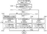
次に、こうして構成された実施例のハイブリッド自動車20の動作、特に、インバータ41,42をシャットダウンしている状態(トランジスタT11〜T16,T21〜T26の全てをオフとしている状態)でエンジン22を運転しながら走行するインバータレス走行(退避走行)時の動作について説明する。ここで、インバータレス走行は、HV走行モードでの走行中に、インバータ41,42の異常や、インバータ41,42の制御に用いるセンサ(回転位置検出センサ43,44など)の異常が生じたときに行なわれる。図3は、実施例のHVECU70により実行されるインバータレス走行時制御ルーチンの一例を示すフローチャートである。このルーチンは、インバータレス走行時に繰り返し実行される。なお、インバータレス走行時には、昇降圧コンバータ55については、高電圧側電力ライン54aの目標電圧VH*に所定電圧VHset(例えば、330Vや350V,370Vなど)を設定して、高電圧側電力ライン54aの電圧VHが目標電圧VH*となるようにトランジスタT31,T32のスイッチング制御を行なう。
Next, the operation of the
本ルーチンが実行されると、HVECU70は、アクセル開度AccやモータMG1,MG2の回転数Nm1を入力する(ステップS100)。ここで、アクセル開度Accは、アクセルペダルポジションセンサ84により検出された値を入力している。モータMG1,MG2の回転数Nm1,Nm2は、回転位置検出センサ43,44により検出されたモータMG1,MG2の回転子の回転位置θm1,θm2に基づいて演算された値をモータECU40から通信により入力したり、車速センサ88により検出された車速Vなどに基づいて演算された値を入力している。
When this routine is executed, the
こうしてデータを入力すると、入力したアクセル開度Accと閾値Arefとを比較する(ステップS110)と共に、モータMG1の回転数Nm1と閾値Nrefとを比較する(ステップS120)。ここで、閾値Arefは、運転者が駆動軸36への駆動トルクの出力を要求しているか否か(運転者による駆動力要求があるか否か)を判定するのに用いられる閾値であり、例えば、1%,3%,5%などを用いることができる。閾値Nrefは、モータMG1の回転に伴う逆起電圧Vcefに基づく回生トルクTcefが生じるか否かを判定するのに用いられる閾値である。ここで、閾値Nrefについて説明する。 When the data is input in this way, the input accelerator opening degree Acc and the threshold value Aref are compared (step S110), and the rotation speed Nm1 of the motor MG1 and the threshold value Nref are compared (step S120). Here, the threshold value Aref is a threshold value used to determine whether or not the driver requests the output of the drive torque to the drive shaft 36 (whether or not there is a drive force request by the driver). For example, 1%, 3%, 5% and the like can be used. The threshold value Nref is a threshold value used for determining whether or not a regenerative torque Tcef based on the counter electromotive voltage Vcef accompanying the rotation of the motor MG1 is generated. Here, the threshold value Nref will be described.
図4は、高電圧側電力ライン54aの電圧VHが所定電圧VHsetのときのモータMG1の回転数Nm1とモータMG1の回転に伴う逆起電圧Vcefに基づく回生トルクTcefとの関係を説明するための説明図である。図中、モータMG1に回生トルクTcefが生じない領域には、ハッチングを施している。モータMG1の逆起電圧Vcefが高電圧側電力ライン54aの電圧VHよりも高いときには、モータMG1の逆起電圧Vcefと高電圧側電力ライン54aの電圧VHとの電圧差(Vcef−VH)に基づく回生トルクTcefがモータMG1で発生する。回生トルクTcefは、詳細には、エンジン22の運転に伴ってモータMG1が連れ回され、モータMG1の逆起電圧Vcefに基づく電力がインバータ41のダイオードD11〜D16により整流されて高電圧側電力ライン54a,昇降圧コンバータ55,低電圧側電力ライン54bを介してバッテリ50に供給されるのに伴って発生する。モータMG1の逆起電圧Vcefが高電圧側電力ライン54aの電圧VH以下のときには、モータMG1に回生トルクTcefが発生しない。ここで、モータMG1の逆起電圧Vcefは、モータMG1の角速度ωm1と逆起電圧定数Keとの積に相当する。このことを踏まえ、実施例では、閾値Nrefを、モータMG1の逆起電圧Vcefが高電圧側電力ライン54aの電圧VHと等しくなる回転数、例えば、1500rpmや1750rpm,2000rpmなどを用いている。なお、高電圧側電力ライン54aの電圧VHが所定電圧VHsetで一定ではなく変化する場合には、電圧VHの変化に応じて閾値Nrefを変化させてもよい。
FIG. 4 is for explaining the relationship between the rotation speed Nm1 of the motor MG1 and the regenerative torque Tcef based on the counter electromotive voltage Vcef accompanying the rotation of the motor MG1 when the voltage VH of the high voltage
ステップS110でアクセル開度Accが閾値Aref以上であり、且つ、モータMG1の回転数Nm1が閾値Nrefより高いときには、運転者からの駆動力要求があり、且つ、モータMG1で回生トルクTcefを発生させることができると判断して、モータMG1の目標回転数Nm1*に所定回転数Nm1setを設定する(ステップS130)。所定回転数Nm1setは、例えば、4000rpmや5000rpm,6000rpmなどを用いている。 When the accelerator opening Acc is equal to or higher than the threshold Aref in step S110 and the rotation speed Nm1 of the motor MG1 is higher than the threshold Nref, there is a driving force request from the driver and the motor MG1 generates the regenerative torque Tcef. It is determined that this is possible, and a predetermined rotation speed Nm1set is set in the target rotation speed Nm1 * of the motor MG1 (step S130). For the predetermined rotation speed Nm1set, for example, 4000 rpm, 5000 rpm, 6000 rpm, or the like is used.
図5は、インバータレス走行でモータMG1の回転数Nm1が閾値Nrefより高いときのプラネタリギヤ30の共線図の一例を示す説明図である。図中、左のS軸はモータMG1の回転数Nm1であるプラネタリギヤ30のサンギヤの回転数を示し、C軸はエンジン22の回転数Neであるプラネタリギヤ30のキャリヤの回転数を示し、R軸はモータMG2の回転数Nm2(および駆動軸36の回転数Nd)であるプラネタリギヤ30のリングギヤの回転数を示す。また、図中、「ρ」は、プラネタリギヤ30のギヤ比(サンギヤの歯数/リングギヤの歯数)を示す。モータMG1の回転数Nm1が閾値Nrefより高いときには、モータMG1の逆起電圧Vcefが高電圧側電力ライン54aの電圧VHよりも高く、図示するように、モータMG1の逆起電圧Vcefと高電圧側電力ライン54aの電圧VHとの電圧差(Vcef−VH)に基づく回生トルクTcefがモータMG1で生じ、回生トルクTcefに基づく駆動トルク(反力トルク)Trf(=−Tcef/ρ)が駆動軸36に出力される。
FIG. 5 is an explanatory diagram showing an example of a collinear diagram of the
こうしてモータMG1の目標回転数Nm1*を設定すると、モータMG1の目標回転数Nm1*とモータMG2の回転数Nm2(駆動軸36の回転数Nd)とプラネタリギヤ30のギヤ比ρとを用いて式(1)によりエンジン22の目標回転数Ne*を設定して(ステップS140)、目標回転数Ne*をエンジンECU24に送信すると共にシャットダウン指令をモータECU40に送信して(ステップS150)、本ルーチンを終了する。ここで、式(1)は、図5を用いれば容易に導くことができる。エンジンECU24は、エンジン22の目標回転数Ne*を受信すると、エンジン22の回転数Neが目標回転数Ne*となるようにエンジン22の吸入空気量制御や燃料噴射制御,点火制御を行なう。モータECU40は、シャットダウン指令を受信すると、インバータ41,42をシャットダウンする。こうした制御により、アクセル開度Accが閾値Aref以上であり、且つ、モータMG1の回転数Nm1が閾値Nrefより高いときには、モータMG1の回生トルクTcef1に基づく駆動軸36の駆動トルクを用いて走行することができる。
When the target rotation speed Nm1 * of the motor MG1 is set in this way, the equation (the target rotation speed Nm1 * of the motor MG1, the rotation speed Nm2 of the motor MG2 (the rotation speed Nd of the drive shaft 36), and the gear ratio ρ of the
Ne*=(Nm1*・ρ+Nm2)/(1+ρ) (1) Ne * = (Nm1 * ・ ρ + Nm2) / (1 + ρ) (1)
ステップS110でアクセル開度Accが閾値Aref未満であるときには、運転者からの駆動力要求がないと判断して、エンジン22の目標回転数Ne*に許容下限回転数Neminを設定し(ステップS160)、目標回転数Ne*をエンジンECU24に送信すると共にシャットダウン指令をモータECU40に送信して(ステップS170)、本ルーチンを終了する。本ルーチンを終了する。エンジンECU24は、エンジン22の目標回転数Ne*を受信すると、エンジン22の回転数Neが目標回転数Ne*となるようにエンジン22を制御する。モータECU40は、シャットダウン指令を受信すると、インバータ41,42をシャットダウンする。ここで、エンジン22の許容下限回転数Neminは、エンジン22を自立運転可能な回転数範囲の下限であり、例えば、900rpmや1000rpm,1100rpmなどを用いている。このようにしてエンジン22を許容下限回転数Neminで回転させることにより、モータMG1の回転数Nm1をアクセルオンのときの回転数(所定回転数Neset)よりも充分に低くすることができる。図6は、インバータレス走行でアクセル開度Accが閾値Aref未満であるときのプラネタリギヤ30の共線図の一例を示す説明図である。アクセル開度Accが閾値Aref未満であるときには、図示するように、モータMG1で回生トルクTcef1が発生しないから、駆動軸36に駆動トルクTrfが出力されなくなる。
When the accelerator opening Acc is less than the threshold value Aref in step S110, it is determined that there is no driving force request from the driver, and the allowable lower limit rotation speed Nemin is set in the target rotation speed Ne * of the engine 22 (step S160). , The target rotation speed Ne * is transmitted to the
ステップS110でアクセル開度Accが閾値Aref以上であり、且つ、モータMG1の回転数Nm1が閾値Nref以下であるときには、運転者からの駆動力要求があるものの、モータMG1で回生トルクTcefを発生させることができないと判断して、前回本ルーチンを実行したときに設定されている目標回転数Ne*(前回Ne*)をエンジン22の目標回転数Ne*に設定して(ステップS180)、エンジン22の目標回転数Ne*をエンジンECU24に送信すると共にインバータ41のシャットダウン指令とインバータ42の三相オン指令とをモータECU40に送信して(ステップS190)、本ルーチンを終了する。エンジンECU24は、エンジン22の目標回転数Ne*を受信すると、エンジン22の回転数Neが目標回転数Ne*となるようにエンジン22を制御する。モータECU40は、インバータ41のシャットダウン指令を受信すると、インバータ41をシャットダウンの継続する。モータECU40は、三相オン指令を受信すると、インバータ42の上アームトランジスタ(T21〜T23)および下アームトランジスタ(T24〜T26)の何れか一方の全てをオンとする。
When the accelerator opening Acc is equal to or higher than the threshold Aref and the rotation speed Nm1 of the motor MG1 is equal to or lower than the threshold Nref in step S110, the motor MG1 generates the regenerative torque Tcef, although there is a driving force request from the driver. It is determined that this is not possible, and the target rotation speed Ne * (previous Ne *) set when this routine was executed last time is set to the target rotation speed Ne * of the engine 22 (step S180), and the
図7は、インバータ42を三相オンしたときのプラネタリギヤ30の共線図の一例を示す説明図である。図中、実線は、インバータ42を三相オンする直前のプラネタリギヤ30の共線図の一例を示している。破線は、インバータ42を三相オンしたときのプラネタリギヤ30の共線図の一例を示している。図示するように、インバータ42を三相オンすると、モータMG2の回転数Nm2を低下させる方向のトルク(引きずりトルク)Tdrg2がプラネタリギヤ30を介してモータMG1の回転数を上昇させるトルクTdrg1(=−ρ・Tdrg2)としてモータMG1の回転軸に出力される。これにより、モータMG1の回転数Nm1を上昇させることができる。また、一般に、モータMG2は、エンジン22より制御応答性が良い。そのため、エンジン22の回転数Neを上昇させてモータMG1の回転数Nm1を上昇させるより、インバータ42を三相オンとしてモータMG1の回転数Nm1を上昇させるほうが、より迅速に回転数Nm1を上昇させることができる。
FIG. 7 is an explanatory diagram showing an example of a collinear diagram of the
なお、こうしてモータMG1の回転数Nm1が上昇して閾値Nrefより高くなったときには、ステップS130の処理へ進み、モータMG1の目標回転数Nm1*とエンジン22の目標回転数Ne*を設定し(ステップS130,S140)、エンジン22の目標回転数Ne*をエンジンECU24に送信すると共にシャットダウン指令をモータECU40に送信して(ステップS150)、本ルーチンを終了する。エンジンECU24は、エンジン22の目標回転数Ne*を受信すると、エンジン22の回転数Neが目標回転数Ne*となるようにエンジン22を制御する。モータECU40は、シャットダウン指令を受信すると、インバータ41,42をシャットダウンする。これにより、モータMG1の回生トルクTcef1に基づく駆動軸36の駆動トルクを用いてインバータレス走行することができる。
When the rotation speed Nm1 of the motor MG1 rises and becomes higher than the threshold Nref in this way, the process proceeds to step S130, and the target rotation speed Nm1 * of the motor MG1 and the target rotation speed Ne * of the
以上説明した実施例のハイブリッド自動車20によれば、インバータレス走行中にアクセル開度Accが閾値Aref以上になった場合において、モータMG1の回転数Nm1が閾値Nref以下であるときには、インバータ42を三相オンすることにより、モータMG1の回転数Nm1をより迅速に閾値Nrefより高くすることができる。また、その後に、モータMG1の回転数Nm1が閾値Nref以上となったときには、インバータ42をシャットダウンするから、インバータレス走行により走行することができる。
According to the
実施例のハイブリッド自動車20では、ステップS180,S190で前回Ne*をエンジン22の目標回転数Ne*に設定してエンジン22の回転数Neを保持しながらインバータ42を三相オンしているが、エンジン22の回転数Neを上昇させながらインバータ42を三相オンしてもよい。
In the
実施例のハイブリッド自動車20では、昇降圧コンバータ55を備えるものとしたが、この昇降圧コンバータ55を備えないものとしてもよい。
In the
実施例のハイブリッド自動車20では、蓄電装置として、バッテリ50を用いるものとしたが、キャパシタなどの蓄電可能な装置であれば如何なる装置を用いるものとしてもよい。
In the
実施例のハイブリッド自動車20では、エンジンECU24とモータECU40とバッテリECU52とHVECU70とを備えるものとしたが、これらのうちの少なくとも2つを単一の電子制御ユニットとして構成するものとしてもよい。
In the
実施例の主要な要素と課題を解決するための手段の欄に記載した発明の主要な要素との対応関係について説明する。実施例では、エンジン22が「エンジン」に相当し、モータMG1が「第1モータ」に相当し、プラネタリギヤ30が「プラネタリギヤ」に相当し、モータMG2が「第2モータ」に相当し、インバータ41が「第1インバータ」に相当し、インバータ42が「第2インバータ」に相当し、バッテリ50が「蓄電装置」に相当し、HVECU70とエンジンECU24とモータECU40とが「制御装置」に相当する。
The correspondence between the main elements of the examples and the main elements of the invention described in the column of means for solving the problem will be described. In the embodiment, the
なお、実施例の主要な要素と課題を解決するための手段の欄に記載した発明の主要な要素との対応関係は、実施例が課題を解決するための手段の欄に記載した発明を実施するための形態を具体的に説明するための一例であることから、課題を解決するための手段の欄に記載した発明の要素を限定するものではない。即ち、課題を解決するための手段の欄に記載した発明についての解釈はその欄の記載に基づいて行なわれるべきものであり、実施例は課題を解決するための手段の欄に記載した発明の具体的な一例に過ぎないものである。 As for the correspondence between the main elements of the examples and the main elements of the invention described in the column of means for solving the problem, the invention described in the column of means for solving the problem in the examples is carried out. Since it is an example for specifically explaining the form for solving the problem, the elements of the invention described in the column of means for solving the problem are not limited. That is, the interpretation of the invention described in the column of means for solving the problem should be performed based on the description in the column, and the examples are the inventions described in the column of means for solving the problem. It is just a concrete example.
以上、本発明を実施するための形態について実施例を用いて説明したが、本発明はこうした実施例に何等限定されるものではなく、本発明の要旨を逸脱しない範囲内において、種々なる形態で実施し得ることは勿論である。 Although the embodiments for carrying out the present invention have been described above with reference to examples, the present invention is not limited to these examples, and various embodiments are used without departing from the gist of the present invention. Of course, it can be done.
本発明は、ハイブリッド車両の製造産業などに利用可能である。 The present invention can be used in the manufacturing industry of hybrid vehicles and the like.
20 ハイブリッド自動車、22 エンジン、23 クランクポジションセンサ、24 エンジン用電子制御ユニット(エンジンECU)、26 クランクシャフト、28 ダンパ、30 プラネタリギヤ、36 駆動軸、38 デファレンシャルギヤ、39a,39b 駆動輪、40 モータ用電子制御ユニット(モータECU)、41,42 インバータ、43,44 回転位置検出センサ、45u,45v,46u,46v 電流センサ、50 バッテリ、51a,57a,58a 電圧センサ、51b 電流センサ、51c 温度センサ、52 バッテリ用電子制御ユニット(バッテリECU)、54a 高電圧側電力ライン、54b 低電圧側電力ライン、55 昇降圧コンバータ、56 システムメインリレー、57,58 コンデンサ、70 ハイブリッド用電子制御ユニット(HVECU)、80 イグニッションスイッチ、81 シフトレバー、82 シフトポジションセンサ、83 アクセルペダル、84 アクセルペダルポジションセンサ、85 ブレーキペダル、86 ブレーキペダルポジションセンサ、88 車速センサ、D11〜D16,D21〜D26,D31,D32 ダイオード、L リアクトル、MG1,MG2 モータ、T11〜T16,T21〜T26,T31,T32 トランジスタ。 20 hybrid vehicle, 22 engine, 23 crank position sensor, 24 electronic control unit for engine (engine ECU), 26 crank shaft, 28 damper, 30 planetary gear, 36 drive shaft, 38 differential gear, 39a, 39b drive wheel, 40 motor Electronic control unit (motor ECU), 41,42 inverter, 43,44 rotation position detection sensor, 45u, 45v, 46u, 46v current sensor, 50 battery, 51a, 57a, 58a voltage sensor, 51b current sensor, 51c temperature sensor, 52 Electronic control unit for battery (battery ECU), 54a high voltage side power line, 54b low voltage side power line, 55 buck-boost converter, 56 system main relay, 57,58 capacitor, 70 electronic control unit for hybrid (HVECU), 80 Ignition switch, 81 shift lever, 82 shift position sensor, 83 accelerator pedal, 84 accelerator pedal position sensor, 85 brake pedal, 86 brake pedal position sensor, 88 vehicle speed sensor, D11 to D16, D21 to D26, D31, D32 diode, L reactor, MG1, MG2 motor, T11-T16, T21-T26, T31, T32 transistors.
Claims (2)
回転に伴って逆起電圧を発生する第1モータと、
前記第1モータと前記エンジンと車軸に連結された駆動軸との3軸に3つの回転要素が共線図において前記第1モータ,前記エンジン,前記駆動軸の順番に並ぶように接続されたプラネタリギヤと、
前記駆動軸に動力を入出力可能な第2モータと、
前記第1モータを駆動する第1インバータと、
前記第2モータを駆動する第2インバータと、
前記第1,第2インバータに電力ラインを介して接続された蓄電装置と、
前記エンジンと前記第1,第2インバータとを制御する制御装置と、
を備えるハイブリッド車両であって、
前記制御装置は、前記第1,第2インバータをシャットダウンしている状態で前記エンジンを運転しながら走行する所定走行時に、アクセル操作量が所定操作量以上である場合において、前記第1モータの回転数が所定回転数以下であるときには、前記第1モータの回転数が前記所定回転数となるまで、前記エンジンの回転数が保持されるまたは上昇するように前記エンジンを運転しながら、前記第2インバータを三相オンする、
ハイブリッド車両。 With the engine
The first motor, which generates a counter electromotive voltage as it rotates,
A planetary gear in which three rotating elements are connected to three axes of the first motor, the engine, and a drive shaft connected to an axle so as to be arranged in the order of the first motor, the engine, and the drive shaft in a collinear diagram. When,
A second motor that can input and output power to the drive shaft,
The first inverter that drives the first motor and
The second inverter that drives the second motor and
A power storage device connected to the first and second inverters via a power line, and
A control device that controls the engine and the first and second inverters,
It is a hybrid vehicle equipped with
The control device rotates the first motor when the accelerator operating amount is equal to or greater than the predetermined operating amount during a predetermined traveling while driving the engine with the first and second inverters shut down. When the number is equal to or less than the predetermined rotation speed, the second engine is operated so that the rotation speed of the engine is maintained or increased until the rotation speed of the first motor reaches the predetermined rotation speed . Turn on the three phases of the inverter,
Hybrid vehicle.
前記制御装置は、前記所定走行時に前記アクセル操作量が前記所定操作量以上で前記第1モータの回転数が前記所定回転数以下であることにより前記エンジンの回転数が保持されるまたは上昇するように前記エンジンを運転しながら前記第2インバータを三相オンした場合において、前記第1モータの回転数が前記所定回転数以上となったときには、前記第2インバータをシャットダウンして前記所定走行により走行する、
ハイブリッド車両。
The hybrid vehicle according to claim 1.
The control device keeps or increases the rotation speed of the engine when the accelerator operation amount is equal to or more than the predetermined operation amount and the rotation speed of the first motor is equal to or less than the predetermined rotation speed during the predetermined travel. When the second inverter is turned on in three phases while the engine is being operated, and the rotation speed of the first motor becomes equal to or higher than the predetermined rotation speed, the second inverter is shut down and the vehicle travels by the predetermined running. To do,
Hybrid vehicle.
Priority Applications (3)
| Application Number | Priority Date | Filing Date | Title |
|---|---|---|---|
| JP2017086155A JP6812895B2 (en) | 2017-04-25 | 2017-04-25 | Hybrid vehicle |
| US15/954,861 US10730506B2 (en) | 2017-04-25 | 2018-04-17 | Hybrid vehicle and control method therefor |
| CN201810379574.2A CN108725426B (en) | 2017-04-25 | 2018-04-25 | Hybrid vehicle and control method thereof |
Applications Claiming Priority (1)
| Application Number | Priority Date | Filing Date | Title |
|---|---|---|---|
| JP2017086155A JP6812895B2 (en) | 2017-04-25 | 2017-04-25 | Hybrid vehicle |
Publications (2)
| Publication Number | Publication Date |
|---|---|
| JP2018184059A JP2018184059A (en) | 2018-11-22 |
| JP6812895B2 true JP6812895B2 (en) | 2021-01-13 |
Family
ID=63939221
Family Applications (1)
| Application Number | Title | Priority Date | Filing Date |
|---|---|---|---|
| JP2017086155A Active JP6812895B2 (en) | 2017-04-25 | 2017-04-25 | Hybrid vehicle |
Country Status (3)
| Country | Link |
|---|---|
| US (1) | US10730506B2 (en) |
| JP (1) | JP6812895B2 (en) |
| CN (1) | CN108725426B (en) |
Families Citing this family (1)
| Publication number | Priority date | Publication date | Assignee | Title |
|---|---|---|---|---|
| JP6818835B1 (en) * | 2019-10-02 | 2021-01-20 | 株式会社ケーヒン | Power controller |
Family Cites Families (13)
| Publication number | Priority date | Publication date | Assignee | Title |
|---|---|---|---|---|
| GB9012365D0 (en) * | 1990-06-02 | 1990-07-25 | Jaguar Cars | Motor vehicles |
| JP4075863B2 (en) * | 2004-06-07 | 2008-04-16 | 株式会社デンソー | Electric torque using vehicle |
| JP4784478B2 (en) * | 2006-04-20 | 2011-10-05 | 株式会社デンソー | Control device for multiphase rotating electrical machine |
| JP2012136064A (en) * | 2010-12-24 | 2012-07-19 | Toyota Motor Corp | Hybrid vehicle and control method thereof |
| JP2013203116A (en) * | 2012-03-27 | 2013-10-07 | Toyota Motor Corp | Hybrid vehicle and method for controlling the same |
| JP5724975B2 (en) * | 2012-09-18 | 2015-05-27 | トヨタ自動車株式会社 | Control device for vehicle |
| KR101526391B1 (en) * | 2013-11-27 | 2015-06-08 | 현대자동차 주식회사 | Motor controlling systen and motor controlling method |
| WO2015114795A1 (en) * | 2014-01-31 | 2015-08-06 | 本田技研工業株式会社 | Power plant |
| JP6183339B2 (en) * | 2014-12-02 | 2017-08-23 | トヨタ自動車株式会社 | Hybrid car |
| JP2017043299A (en) * | 2015-08-28 | 2017-03-02 | トヨタ自動車株式会社 | Hybrid vehicle |
| JP6252574B2 (en) * | 2015-09-25 | 2017-12-27 | トヨタ自動車株式会社 | Hybrid vehicle |
| JP6760194B2 (en) * | 2017-04-25 | 2020-09-23 | トヨタ自動車株式会社 | Hybrid vehicle |
| JP6772947B2 (en) * | 2017-04-27 | 2020-10-21 | トヨタ自動車株式会社 | Hybrid car |
-
2017
- 2017-04-25 JP JP2017086155A patent/JP6812895B2/en active Active
-
2018
- 2018-04-17 US US15/954,861 patent/US10730506B2/en active Active
- 2018-04-25 CN CN201810379574.2A patent/CN108725426B/en not_active Expired - Fee Related
Also Published As
| Publication number | Publication date |
|---|---|
| CN108725426A (en) | 2018-11-02 |
| JP2018184059A (en) | 2018-11-22 |
| US20190315335A1 (en) | 2019-10-17 |
| US10730506B2 (en) | 2020-08-04 |
| CN108725426B (en) | 2021-04-13 |
Similar Documents
| Publication | Publication Date | Title |
|---|---|---|
| JP6392653B2 (en) | Hybrid car | |
| JP6888512B2 (en) | Hybrid car | |
| JP2021084537A (en) | Hybrid vehicle | |
| JP6760194B2 (en) | Hybrid vehicle | |
| JP6575544B2 (en) | Hybrid car | |
| JP6652081B2 (en) | Hybrid car | |
| JP6631571B2 (en) | Hybrid car | |
| JP6772947B2 (en) | Hybrid car | |
| JP6451726B2 (en) | Hybrid car | |
| CN108569273B (en) | Hybrid vehicle and control method thereof | |
| JP6969303B2 (en) | Hybrid car | |
| JP6489100B2 (en) | Hybrid car | |
| JP6812895B2 (en) | Hybrid vehicle | |
| JP6451725B2 (en) | Hybrid car | |
| JP6888511B2 (en) | Hybrid car | |
| JP6607217B2 (en) | Hybrid car | |
| JP6769366B2 (en) | Hybrid vehicle control device | |
| JP2018167614A (en) | Hybrid vehicular control apparatus | |
| JP6947016B2 (en) | Electric vehicle | |
| JP2015199411A (en) | Hybrid electric vehicle | |
| JP6885303B2 (en) | Hybrid car | |
| JP6874638B2 (en) | Hybrid car | |
| JP6769361B2 (en) | Hybrid vehicle control device | |
| JP7067053B2 (en) | Hybrid car | |
| JP2019199191A (en) | Hybrid automobile |
Legal Events
| Date | Code | Title | Description |
|---|---|---|---|
| A621 | Written request for application examination |
Free format text: JAPANESE INTERMEDIATE CODE: A621 Effective date: 20191028 |
|
| A131 | Notification of reasons for refusal |
Free format text: JAPANESE INTERMEDIATE CODE: A131 Effective date: 20200519 |
|
| A521 | Written amendment |
Free format text: JAPANESE INTERMEDIATE CODE: A523 Effective date: 20200713 |
|
| A131 | Notification of reasons for refusal |
Free format text: JAPANESE INTERMEDIATE CODE: A131 Effective date: 20200804 |
|
| A521 | Written amendment |
Free format text: JAPANESE INTERMEDIATE CODE: A523 Effective date: 20200928 |
|
| TRDD | Decision of grant or rejection written | ||
| A01 | Written decision to grant a patent or to grant a registration (utility model) |
Free format text: JAPANESE INTERMEDIATE CODE: A01 Effective date: 20201117 |
|
| A61 | First payment of annual fees (during grant procedure) |
Free format text: JAPANESE INTERMEDIATE CODE: A61 Effective date: 20201130 |
|
| R151 | Written notification of patent or utility model registration |
Ref document number: 6812895 Country of ref document: JP Free format text: JAPANESE INTERMEDIATE CODE: R151 |