JP6794877B2 - Motor inverter - Google Patents
Motor inverter Download PDFInfo
- Publication number
- JP6794877B2 JP6794877B2 JP2017041907A JP2017041907A JP6794877B2 JP 6794877 B2 JP6794877 B2 JP 6794877B2 JP 2017041907 A JP2017041907 A JP 2017041907A JP 2017041907 A JP2017041907 A JP 2017041907A JP 6794877 B2 JP6794877 B2 JP 6794877B2
- Authority
- JP
- Japan
- Prior art keywords
- capacitor
- phase
- motor
- voltage
- circuit
- Prior art date
- Legal status (The legal status is an assumption and is not a legal conclusion. Google has not performed a legal analysis and makes no representation as to the accuracy of the status listed.)
- Active
Links
Images


Classifications
-
- H—ELECTRICITY
- H02—GENERATION; CONVERSION OR DISTRIBUTION OF ELECTRIC POWER
- H02M—APPARATUS FOR CONVERSION BETWEEN AC AND AC, BETWEEN AC AND DC, OR BETWEEN DC AND DC, AND FOR USE WITH MAINS OR SIMILAR POWER SUPPLY SYSTEMS; CONVERSION OF DC OR AC INPUT POWER INTO SURGE OUTPUT POWER; CONTROL OR REGULATION THEREOF
- H02M7/00—Conversion of ac power input into dc power output; Conversion of dc power input into ac power output
- H02M7/42—Conversion of dc power input into ac power output without possibility of reversal
- H02M7/44—Conversion of dc power input into ac power output without possibility of reversal by static converters
- H02M7/48—Conversion of dc power input into ac power output without possibility of reversal by static converters using discharge tubes with control electrode or semiconductor devices with control electrode
- H02M7/53—Conversion of dc power input into ac power output without possibility of reversal by static converters using discharge tubes with control electrode or semiconductor devices with control electrode using devices of a triode or transistor type requiring continuous application of a control signal
- H02M7/537—Conversion of dc power input into ac power output without possibility of reversal by static converters using discharge tubes with control electrode or semiconductor devices with control electrode using devices of a triode or transistor type requiring continuous application of a control signal using semiconductor devices only, e.g. single switched pulse inverters
- H02M7/5387—Conversion of dc power input into ac power output without possibility of reversal by static converters using discharge tubes with control electrode or semiconductor devices with control electrode using devices of a triode or transistor type requiring continuous application of a control signal using semiconductor devices only, e.g. single switched pulse inverters in a bridge configuration
- H02M7/53871—Conversion of dc power input into ac power output without possibility of reversal by static converters using discharge tubes with control electrode or semiconductor devices with control electrode using devices of a triode or transistor type requiring continuous application of a control signal using semiconductor devices only, e.g. single switched pulse inverters in a bridge configuration with automatic control of output voltage or current
- H02M7/53875—Conversion of dc power input into ac power output without possibility of reversal by static converters using discharge tubes with control electrode or semiconductor devices with control electrode using devices of a triode or transistor type requiring continuous application of a control signal using semiconductor devices only, e.g. single switched pulse inverters in a bridge configuration with automatic control of output voltage or current with analogue control of three-phase output
-
- H—ELECTRICITY
- H02—GENERATION; CONVERSION OR DISTRIBUTION OF ELECTRIC POWER
- H02P—CONTROL OR REGULATION OF ELECTRIC MOTORS, ELECTRIC GENERATORS OR DYNAMO-ELECTRIC CONVERTERS; CONTROLLING TRANSFORMERS, REACTORS OR CHOKE COILS
- H02P27/00—Arrangements or methods for the control of AC motors characterised by the kind of supply voltage
- H02P27/04—Arrangements or methods for the control of AC motors characterised by the kind of supply voltage using variable-frequency supply voltage, e.g. inverter or converter supply voltage
- H02P27/06—Arrangements or methods for the control of AC motors characterised by the kind of supply voltage using variable-frequency supply voltage, e.g. inverter or converter supply voltage using dc to ac converters or inverters
-
- H—ELECTRICITY
- H02—GENERATION; CONVERSION OR DISTRIBUTION OF ELECTRIC POWER
- H02M—APPARATUS FOR CONVERSION BETWEEN AC AND AC, BETWEEN AC AND DC, OR BETWEEN DC AND DC, AND FOR USE WITH MAINS OR SIMILAR POWER SUPPLY SYSTEMS; CONVERSION OF DC OR AC INPUT POWER INTO SURGE OUTPUT POWER; CONTROL OR REGULATION THEREOF
- H02M1/00—Details of apparatus for conversion
- H02M1/32—Means for protecting converters other than automatic disconnection
-
- H—ELECTRICITY
- H02—GENERATION; CONVERSION OR DISTRIBUTION OF ELECTRIC POWER
- H02M—APPARATUS FOR CONVERSION BETWEEN AC AND AC, BETWEEN AC AND DC, OR BETWEEN DC AND DC, AND FOR USE WITH MAINS OR SIMILAR POWER SUPPLY SYSTEMS; CONVERSION OF DC OR AC INPUT POWER INTO SURGE OUTPUT POWER; CONTROL OR REGULATION THEREOF
- H02M1/00—Details of apparatus for conversion
- H02M1/36—Means for starting or stopping converters
-
- H—ELECTRICITY
- H02—GENERATION; CONVERSION OR DISTRIBUTION OF ELECTRIC POWER
- H02M—APPARATUS FOR CONVERSION BETWEEN AC AND AC, BETWEEN AC AND DC, OR BETWEEN DC AND DC, AND FOR USE WITH MAINS OR SIMILAR POWER SUPPLY SYSTEMS; CONVERSION OF DC OR AC INPUT POWER INTO SURGE OUTPUT POWER; CONTROL OR REGULATION THEREOF
- H02M7/00—Conversion of ac power input into dc power output; Conversion of dc power input into ac power output
- H02M7/42—Conversion of dc power input into ac power output without possibility of reversal
- H02M7/44—Conversion of dc power input into ac power output without possibility of reversal by static converters
- H02M7/48—Conversion of dc power input into ac power output without possibility of reversal by static converters using discharge tubes with control electrode or semiconductor devices with control electrode
- H02M7/53—Conversion of dc power input into ac power output without possibility of reversal by static converters using discharge tubes with control electrode or semiconductor devices with control electrode using devices of a triode or transistor type requiring continuous application of a control signal
- H02M7/537—Conversion of dc power input into ac power output without possibility of reversal by static converters using discharge tubes with control electrode or semiconductor devices with control electrode using devices of a triode or transistor type requiring continuous application of a control signal using semiconductor devices only, e.g. single switched pulse inverters
- H02M7/5375—Conversion of dc power input into ac power output without possibility of reversal by static converters using discharge tubes with control electrode or semiconductor devices with control electrode using devices of a triode or transistor type requiring continuous application of a control signal using semiconductor devices only, e.g. single switched pulse inverters with special starting equipment
-
- H—ELECTRICITY
- H02—GENERATION; CONVERSION OR DISTRIBUTION OF ELECTRIC POWER
- H02P—CONTROL OR REGULATION OF ELECTRIC MOTORS, ELECTRIC GENERATORS OR DYNAMO-ELECTRIC CONVERTERS; CONTROLLING TRANSFORMERS, REACTORS OR CHOKE COILS
- H02P29/00—Arrangements for regulating or controlling electric motors, appropriate for both AC and DC motors
- H02P29/02—Providing protection against overload without automatic interruption of supply
- H02P29/024—Detecting a fault condition, e.g. short circuit, locked rotor, open circuit or loss of load
- H02P29/0241—Detecting a fault condition, e.g. short circuit, locked rotor, open circuit or loss of load the fault being an overvoltage
-
- H—ELECTRICITY
- H02—GENERATION; CONVERSION OR DISTRIBUTION OF ELECTRIC POWER
- H02M—APPARATUS FOR CONVERSION BETWEEN AC AND AC, BETWEEN AC AND DC, OR BETWEEN DC AND DC, AND FOR USE WITH MAINS OR SIMILAR POWER SUPPLY SYSTEMS; CONVERSION OF DC OR AC INPUT POWER INTO SURGE OUTPUT POWER; CONTROL OR REGULATION THEREOF
- H02M7/00—Conversion of ac power input into dc power output; Conversion of dc power input into ac power output
- H02M7/42—Conversion of dc power input into ac power output without possibility of reversal
- H02M7/44—Conversion of dc power input into ac power output without possibility of reversal by static converters
- H02M7/48—Conversion of dc power input into ac power output without possibility of reversal by static converters using discharge tubes with control electrode or semiconductor devices with control electrode
- H02M7/53—Conversion of dc power input into ac power output without possibility of reversal by static converters using discharge tubes with control electrode or semiconductor devices with control electrode using devices of a triode or transistor type requiring continuous application of a control signal
- H02M7/537—Conversion of dc power input into ac power output without possibility of reversal by static converters using discharge tubes with control electrode or semiconductor devices with control electrode using devices of a triode or transistor type requiring continuous application of a control signal using semiconductor devices only, e.g. single switched pulse inverters
- H02M7/5387—Conversion of dc power input into ac power output without possibility of reversal by static converters using discharge tubes with control electrode or semiconductor devices with control electrode using devices of a triode or transistor type requiring continuous application of a control signal using semiconductor devices only, e.g. single switched pulse inverters in a bridge configuration
- H02M7/53871—Conversion of dc power input into ac power output without possibility of reversal by static converters using discharge tubes with control electrode or semiconductor devices with control electrode using devices of a triode or transistor type requiring continuous application of a control signal using semiconductor devices only, e.g. single switched pulse inverters in a bridge configuration with automatic control of output voltage or current
Description
本発明は、モータインバータに関するものである。 The present invention relates to a motor inverter.
プリチャージ回路を備えたモータインバータにおいて、特許文献1にはプリチャージ状態においてインバータ回路のスイッチング素子をスイッチング動作させ、プリチャージ状態においてインバータ回路のスイッチング素子をスイッチング動作させたときのインバータ回路に流れる電流またはコンデンサの電圧からショートの有無を判定している。
In a motor inverter provided with a precharge circuit,
ところで、特許文献1に開示の技術では同公報の図5で示されているようにチェック電圧維持のための処理を行っており、そのための演算が必要となっている。特に、プリチャージ回路を備えたモータインバータにおいてショートの有無を判定する際に特許文献1に開示の手法を用いると、プリチャージを十分に完了させる時間が必要であり、早急に運転可能状態に立ち上げたい場合においてはこの立ち上げ時間により制限される。
By the way, in the technique disclosed in
本発明の目的は、容易にショートの有無を判定することができるモータインバータを提供することにある。 An object of the present invention is to provide a motor inverter capable of easily determining the presence or absence of a short circuit.
請求項1に記載の発明では、ブリッジ接続された複数のスイッチング素子を有し、入力側に直流電源が接続されるとともに出力側にモータの各相の巻線が接続され、前記スイッチング素子のスイッチング動作により前記モータの各相の巻線が通電されて前記モータを駆動するためのインバータ回路と、前記インバータ回路の入力側に並列に接続されたコンデンサと、前記直流電源に操作スイッチを介して接続され、前記操作スイッチのオンに伴って前記インバータ回路の入力側と前記直流電源との間に接続されたメインリレーの閉路に先立ち前記コンデンサをプリチャージするためのプリチャージ回路と、を備えたモータインバータであって、前記プリチャージ回路における前記コンデンサへの電荷の蓄積ラインに設けた開閉手段と、前記操作スイッチのオンに伴って前記開閉手段を閉じ前記コンデンサの電圧が予め定めたショートの有無の判定が可能な電圧まで上昇することにより前記コンデンサに電荷が溜まると、前記開閉手段を開いた状態において前記インバータ回路のスイッチング素子をスイッチング動作させる制御手段と、前記コンデンサに電荷が溜まり、かつ、前記開閉手段を開いた状態においてのみ、前記制御手段により前記インバータ回路のスイッチング素子をスイッチング動作させたときの前記インバータ回路に流れる電流および前記コンデンサの電圧の少なくとも一方からショートの有無を判定する判定手段と、を備えたことを要旨とする。
The invention according to
請求項1に記載の発明によれば、制御手段により、操作スイッチのオンに伴って開閉手段が閉じコンデンサの電圧が予め定めたショートの有無の判定が可能な電圧まで上昇することによりコンデンサに電荷が溜まると、開閉手段を開いた状態においてインバータ回路のスイッチング素子がスイッチング動作される。判定手段により、コンデンサに電荷が溜まり、かつ、開閉手段を開いた状態において制御手段によりインバータ回路のスイッチング素子をスイッチング動作させたときのインバータ回路に流れる電流およびコンデンサの電圧の少なくとも一方からショートの有無が判定される。
According to the invention of
よって、開閉手段を開いた状態でショートの有無を判定でき、チェック電圧維持のための処理を行うことなく、容易にショートの有無を判定することができる。
請求項2に記載のように、請求項1に記載のモータインバータにおいて、前記判定手段は、前記コンデンサの電圧の降下度合いによりショートの有無を判定するとよい。この場合には、ショートの有無を正確に判定することができる。
Therefore, the presence or absence of a short circuit can be determined with the opening / closing means open, and the presence or absence of a short circuit can be easily determined without performing a process for maintaining the check voltage.
As described in claim 2, in the motor inverter according to
請求項3に記載のように、請求項1又は2に記載のモータインバータにおいて、ショートの有無を判定する際に前記コンデンサの電圧が閾値よりも降下した場合には前記開閉手段を閉じてコンデンサを再度プリチャージしてから前記メインリレーを閉路する再プリチャージ制御手段を更に備えるとよい。この場合には、リレー接点がオン(閉路)する時にコンデンサに急に大電流が流れることを回避してコンデンサを保護することができる。
As described in
本発明によれば、容易にショートの有無を判定することができる。 According to the present invention, the presence or absence of a short circuit can be easily determined.
以下、本発明を具体化した一実施形態を図面に従って説明する。
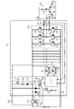
図1に示すように、モータインバータ(三相インバータ)10は、インバータ回路20と、マイコン60を備えている。インバータ回路20の入力側には直流電源としてのバッテリ70が接続されるとともに、出力側にはモータ80が接続されている。モータ80には3相交流モータが使用されている。モータ80は巻線81,82,83を有し、モータ80の各相の巻線81,82,83がインバータ回路20の出力側に接続されている。
Hereinafter, an embodiment embodying the present invention will be described with reference to the drawings.
As shown in FIG. 1, the motor inverter (three-phase inverter) 10 includes an
インバータ回路20は、モータ駆動用素子としての6個のスイッチング素子S1〜S6が設けられている。各スイッチング素子S1〜S6には、IGBT(絶縁ゲートバイポーラ型トランジスタ)が使用されている。なお、スイッチング素子としてパワーMOSFETを使用してもよい。各スイッチング素子S1〜S6には、それぞれ帰還ダイオードD1〜D6が逆並列接続されている。
The
インバータ回路20において、第1および第2のスイッチング素子S1,S2、第3および第4のスイッチング素子S3,S4、第5および第6のスイッチング素子S5,S6がそれぞれ直列に接続されている。そして、第1、第3および第5のスイッチング素子S1,S3,S5がバッテリ70のプラス端子側に接続され、第2、第4および第6のスイッチング素子S2,S4,S6がバッテリ70のマイナス端子側に接続されている。
In the
U相用の上下のアームを構成するスイッチング素子S1,S2の間の接続点はモータ80のU相端子に、V相用の上下のアームを構成するスイッチング素子S3,S4の間の接続点はモータ80のV相端子に、W相用の上下のアームを構成するスイッチング素子S5,S6の間の接続点はモータ80のW相端子に、それぞれ接続されている。このように、インバータ回路20は、ブリッジ接続された複数のスイッチング素子S1〜S6を有する。第1のスイッチング素子S1がU相の上アーム用スイッチング素子であり、第2のスイッチング素子S2がU相の下アーム用スイッチング素子である。第3のスイッチング素子S3がV相の上アーム用スイッチング素子であり、第4のスイッチング素子S4がV相の下アーム用スイッチング素子である。第5のスイッチング素子S5がW相の上アーム用スイッチング素子であり、第6のスイッチング素子S6がW相の下アーム用スイッチング素子である。
The connection point between the switching elements S1 and S2 that form the upper and lower arms for the U phase is to the U phase terminal of the
インバータ回路20とモータ80との間にはU相電流センサ65およびW相電流センサ66が設けられている。U相電流センサ65およびW相電流センサ66はモータ80に供給される3相の電流Iu,Iv,Iwのうちの2相(この実施形態ではU相およびW相)の電流Iu,Iwの電流値を検出する。
A U-phase
インバータ回路20の入力側には、メインコンデンサ40がバッテリ70と並列に接続されている。メインコンデンサ40は複数のコンデンサを並列接続して構成されている。第1、第3および第5のスイッチング素子S1,S3,S5がメインコンデンサ40のプラス端子側に接続され、第2、第4および第6のスイッチング素子S2,S4,S6がメインコンデンサ40のマイナス端子側に接続されている。
A main capacitor 40 is connected in parallel with the
このように、インバータ回路20の入力側には、並列接続されたバッテリ70およびメインコンデンサ40が接続されている。つまり、モータインバータ10に備えられたインバータ回路20の入力側にメインコンデンサ40が並列に接続され、このメインコンデンサ40によりバッテリ70による電源電圧が平滑化される。
In this way, the
インバータの制御装置を構成するマイコン60は、メモリを備え、メモリにはモータ80を駆動するのに必要な各種制御プログラムおよびその実行に必要な各種データやマップが記憶されている。
The
マイコン60には駆動回路(図示略)を介して各スイッチング素子S1〜S6のゲートが接続されている。そして、マイコン60によりスイッチング素子S1〜S6が制御され、バッテリ70の直流が交流に変換されてモータ80の各相の巻線に供給される。これにより、モータ80が駆動される。また、マイコン60にはU相電流センサ65およびW相電流センサ66が接続されている。マイコン60は、各電流センサ65,66の検出信号に基づいて、モータ80を目標出力となるように制御する制御信号を、駆動回路を介して各スイッチング素子S1〜S6に出力する。そして、インバータ回路20はバッテリ70およびメインコンデンサ40から供給される直流を適宜の周波数の3相交流に変換してモータ80の各相の巻線に供給する。つまり、スイッチング素子S1〜S6のスイッチング動作によりモータ80の各相の巻線が通電されてモータ80を駆動することができる。
The gates of the switching elements S1 to S6 are connected to the
バッテリ70のプラス端子と、メインコンデンサ40およびインバータ回路20との間の電源ラインにはメインリレー30が設けられている。即ち、インバータ回路20の入力側とバッテリ70との間にメインリレー30が接続されている。メインリレー30はリレー接点31とリレーコイル32を備えており、リレー接点31が、バッテリ70のプラス端子とメインコンデンサ40およびインバータ回路20との間の電源ラインに挿入されている。そして、リレーコイル32を通電することによりリレー接点31が閉じるようになっている。リレーコイル32の一端は電源回路35に接続されているとともにリレーコイル32の他端はメインリレー駆動用素子(トランジスタ)38および抵抗39を介して接地されている。メインリレー駆動用素子(トランジスタ)38のゲートはマイコン60に接続され、マイコン60によりメインリレー駆動用素子(トランジスタ)38がオンされるとリレーコイル32が励磁される。これにより、メインリレー30のリレー接点31が閉じられる。
A
また、モータインバータ10はプリチャージ回路50を備えている。プリチャージ回路50は、プリチャージ駆動用素子(トランジスタ)51とプリチャージ抵抗52とダイオード53を備えている。プリチャージ駆動用素子(トランジスタ)51とプリチャージ抵抗52とダイオード53とが直列接続されている。プリチャージ駆動用素子(トランジスタ)51の一端はキースイッチ55を介してバッテリ70のプラス端子と接続されているとともに、プリチャージ駆動用素子(トランジスタ)51の他端はプリチャージ抵抗52を介してダイオード53のアノードと接続されている。ダイオード53のカソードは、メインリレー30とメインコンデンサ40の間の接続点Aと接続されている。そして、キースイッチ55が閉じた状態でプリチャージ駆動用素子(トランジスタ)51をオンすることにより、バッテリ70によりキースイッチ55、プリチャージ駆動用素子(トランジスタ)51、プリチャージ抵抗52、ダイオード53を通してメインコンデンサ40をプリチャージすることができる。このように、プリチャージ回路50は、バッテリ70に操作スイッチとしてのキースイッチ55を介して接続され、キースイッチ55のオンに伴ってメインリレー30の閉路に先立ちメインコンデンサ40をプリチャージするためのものである。
Further, the
電源回路35にはダイオード36によりメインリレー30を通してバッテリ70の電力が供給できるとともに、ダイオード37によりキースイッチ55を通してバッテリ70の電力が供給できるようになっている。
The diode 36 can supply the power of the
電圧検出回路61によりメインリレー30とメインコンデンサ40の間の電位が検出され、その結果がマイコン60に送られることによりマイコン60においてメインコンデンサ40の両端電圧(コンデンサ電圧)が検知される。また、電圧検出回路62によりキースイッチ55とプリチャージ駆動用素子(トランジスタ)51との間の電位が検出され、その結果がマイコン60に送られることによりマイコン60においてキースイッチ55のオン/オフ状態が検知される。
The
本実施形態においては、プリチャージ駆動用素子51が、プリチャージ回路50におけるメインコンデンサ40への電荷の蓄積ラインに設けた開閉手段として機能する。つまり、モータインバータ10は、プリチャージ回路50におけるメインコンデンサ40への電荷の蓄積ラインに設けた開閉手段としてのプリチャージ駆動用素子51を備える。
In the present embodiment, the precharge drive element 51 functions as an opening / closing means provided in the charge storage line on the main capacitor 40 in the
次に、モータインバータ10(制御装置)の作用について説明する。
まず、相間ショートが無い正常時のモータの制御動作について説明する。
マイコン60は、スイッチング素子S1,S4,S6を同時にオンにしてU相電流Iuを流す。また、スイッチング素子S3,S2,S6を同時にオンにしてV相電流Ivを流す。さらに、スイッチング素子S5,S2,S4を同時にオンにしてW相電流Iwを流す。このようにして、モータインバータ10の動作として、バッテリ70(メインコンデンサ40)から直流電圧を入力して、ブリッジ接続したスイッチング素子S1〜S6がオン・オフされ、このオン・オフ動作に伴って出力側のモータ80が通電される。このとき、マイコン60において、各相で所望の電流が流れるように調整される。通常動作が終了すると、マイコン60はメインコンデンサ40に蓄えられている電荷をモータ80の巻線に流して放出する(放電する)。
Next, the operation of the motor inverter 10 (control device) will be described.
First, the control operation of the motor in the normal state where there is no interphase short circuit will be described.
The
次に、キースイッチ55のオンに伴い行われる相間ショートの有無の判定処理について説明する。
マイコン60は図2に示す処理を実行する。
Next, the process of determining the presence or absence of a phase-to-phase short circuit performed when the
The
図2において、マイコン60はステップS100でキースイッチ55がオンか否か判定してキースイッチ55がオンされるとステップS101に移行する。図4において、t1のタイミングでキースイッチ55がオンされた状況を示している。図2においてマイコン60はステップS101においてプリチャージ駆動用素子51をオンする。これにより図4においてt1のタイミング以降にはメインコンデンサ40の電圧が上昇していく。その後、図2においてマイコン60はステップS102に移行する。マイコン60はステップS102においてメインコンデンサ40の電圧が閾値に達したか否か判定する。マイコン60はメインコンデンサ40の電圧が閾値に達していないと、ステップS101に戻る。
In FIG. 2, the
図4においては、t2のタイミングでメインコンデンサ40の電圧が閾値に達した状況を示している。図2においてマイコン60はステップS102においてメインコンデンサ40の電圧が閾値に達すると、ステップS103に移行してプリチャージ駆動用素子51をオフする。
FIG. 4 shows a situation in which the voltage of the main capacitor 40 reaches the threshold value at the timing of t2. In FIG. 2, when the voltage of the main capacitor 40 reaches the threshold value in step S102, the
つまり、操作スイッチとしてのキースイッチ55のオンに伴ってプリチャージ駆動用素子51をオンして(閉じて)、メインコンデンサ40の電圧が予め定めたショートの有無の判定が可能な電圧(閾値)まで上昇することによりメインコンデンサ40に電荷が溜まると、プリチャージ駆動用素子51をオフした状態(開いた状態)にする。
That is, the precharge drive element 51 is turned on (closed) when the
その後、マイコン60はステップS104に移行して診断モードを設定して相間ショートの有無の判定を行う。図4においてt2〜t3の期間が診断モードがオンの状態であり、診断モードがオンの状態ではプリチャージ駆動用素子51はオフされている。
After that, the
このように、メインコンデンサ40に電荷が溜まり、かつ、プリチャージ駆動用素子51をオフした状態(開いた状態)において制御手段としてのマイコン60によりインバータ回路20のスイッチング素子S1〜S6をスイッチング動作させたときのインバータ回路20に流れる電流およびメインコンデンサ40の電圧の少なくとも一方から相間ショートの有無を判定する。インバータ回路20に流れる電流は、電流センサ65,66により検出でき、メインコンデンサ40の電圧は電圧検出回路61により検出できる。また、マイコン60は、メインコンデンサ40の電圧の降下度合いにより相間ショートの有無を判定するとよい。
In this way, the switching elements S1 to S6 of the
診断モードにおいては、マイコン60は図3に示す処理を実行する。
図3において、マイコン60はステップS200でスイッチング素子S1〜S6を制御してステップS201においてメインコンデンサ40の電圧の低下量が所定の範囲内か否か判定する。または、マイコン60はステップS201においてインバータ回路20に流れる電流を検出して検出電流が所定の範囲内か否か判定する。
In the diagnostic mode, the
In FIG. 3, the
マイコン60はステップS201においてメインコンデンサ40の電圧の低下量が所定の範囲内である、または、検出電流が所定の範囲内であると、ステップS202において正常と判定する。正常と判定されると、マイコン60はメインリレー30をオンすべくメインリレー駆動用素子38に対しメインリレー駆動出力をオンする。このとき、メインコンデンサ40が充電されているので、突入電流を増加させないでメインリレー30を閉じることができる。
If the amount of decrease in the voltage of the main capacitor 40 is within a predetermined range or the detection current is within a predetermined range in step S201, the
一方、マイコン60はステップS201においてメインコンデンサ40の電圧の低下量が所定の範囲から外れる、または、検出電流が所定の範囲から外れると、ステップS203において異常と判定する。
On the other hand, when the amount of decrease in the voltage of the main capacitor 40 deviates from the predetermined range in step S201 or the detected current deviates from the predetermined range, the
相間ショートの有無の判定処理の例について言及する。
出力端子間のうちのモータインバータ10の外部でのV相−U相間、V相−W相間のショートのチェックは次のように行われる。マイコン60はU相上アームのスイッチング素子S1をパルス印加、U相下アームのスイッチング素子S2をオフ、V相上アームのスイッチング素子S3をオフ、V相下アームのスイッチング素子S4をオン、W相上アームのスイッチング素子S5をオフ、W相下アームのスイッチング素子S6をオンする。これにより、U相の上アーム(スイッチング素子S1)からモータ80を通して電流が流れる状況にする。そして、マイコン60はメインコンデンサ40の電圧の低下量が所定の範囲から外れる、または、検出電流が所定の範囲から外れると異常と判定する。つまり、U−V間の端子間ショート(外部ショート)、あるいは、U−W間の端子間ショート(外部ショート)が発見できる。このようにして異常が検出されると警報等が行われる。
An example of a process for determining the presence or absence of a phase short is described.
Checking for short circuits between the V phase and the U phase and between the V phase and the W phase outside the
出力端子間のうちのモータインバータ10の外部でのV相−U相間、V相−W相間のショートのチェックは次のように行われる。マイコン60は、U相上アームのスイッチング素子S1をオフ、U相下アームのスイッチング素子S2をオン、V相上アームのスイッチング素子S3をパルス印加、V相下アームのスイッチング素子S4をオフ、W相上アームのスイッチング素子S5をオフ、W相下アームのスイッチング素子S6をオンする。これにより、V相の上アーム(スイッチング素子S3)からモータ80を通して電流が流れる状況にする。そして、マイコン60はメインコンデンサ40の電圧の低下量が所定の範囲から外れる、または、検出電流が所定の範囲から外れると異常と判定する。つまり、V−U間の端子間ショート(外部ショート)、あるいは、V−W間の端子間ショート(外部ショート)が発見できる。このようにして異常が検出されると警報等が行われる。
Checking for short circuits between the V phase and the U phase and between the V phase and the W phase outside the
出力端子間のうちのモータインバータ10の外部でのW相−U相間、W相−V相間のショートのチェックは次のように行われる。マイコン60は、U相上アームのスイッチング素子S1をオフ、U相下アームのスイッチング素子S2をオン、V相上アームのスイッチング素子S3をオフ、V相下アームのスイッチング素子S4をオン、W相上アームのスイッチング素子S5をパルス印加、W相下アームのスイッチング素子S6をオフする。これにより、W相の上アーム(スイッチング素子S5)からモータ80を通して電流が流れる状況にする。そして、マイコン60はメインコンデンサ40の電圧の低下量が所定の範囲から外れる、または、検出電流が所定の範囲から外れると異常と判定する。つまり、W−U間の端子間ショート(外部ショート)、あるいは、W−V間の端子間ショート(外部ショート)が発見できる。このようにして異常が検出されると警報等が行われる。
Checking for short circuits between the W phase and the U phase and between the W phase and the V phase outside the
このようにして、図4に示すごとくバッテリ電圧とコンデンサ電圧との電位差が、例えば5V程度ある状態で、プリチャージをやめ、相間ショートチェック(相間ショートの有無の判定)へ移行することができるため、プリチャージ時間を短縮できる。 In this way, as shown in FIG. 4, when the potential difference between the battery voltage and the capacitor voltage is, for example, about 5 V, the precharge can be stopped and the process can be shifted to the interphase short check (determination of the presence or absence of the interphase short). , The precharge time can be shortened.
つまり、プリチャージ駆動用素子51をオフにしてプリチャージ抵抗52を非通電状態とし、チェック中に流れる電流およびメインコンデンサ40の電圧降下量の少なくとも一方で相間ショートか否かを判断する(相間ショートの有無の判定を行う)。また、プリチャージ駆動用素子51はオフであり、リレー接点31をオン(閉路)する前なので、メインコンデンサ40に残った電荷によりモータ80側へチェック電流を流すことになる。
That is, the precharge drive element 51 is turned off to put the
以下、詳しく説明する。
図4に示すように、バッテリ電圧(例えば36V)とコンデンサ電圧との電位差が例えば5Vである状態、即ち、コンデンサ電圧が例えば31Vとなった状態になると、相間ショートの有無を判断することができる状態になったと判断して、プリチャージ駆動用素子51をオフにしてプリチャージを終了する。そして、相間ショートチェック(相間ショートの有無の判定)を開始する。このとき、印加電流などにより想定される電圧降下量が、メインコンデンサ40の容量、モータの巻線81,82,83の抵抗値より決まる値と比較することにより良否が判定できる。つまり、実際にモータに流れた電流、または、電圧降下量が閾値を超えたとき異常と判定する。
The details will be described below.
As shown in FIG. 4, when the potential difference between the battery voltage (for example, 36V) and the capacitor voltage is, for example, 5V, that is, when the capacitor voltage is, for example, 31V, the presence or absence of a phase-to-phase short circuit can be determined. When it is determined that the state has been reached, the precharge drive element 51 is turned off to end the precharge. Then, the interphase short check (determination of the presence or absence of the interphase short) is started. At this time, the quality can be determined by comparing the voltage drop amount assumed by the applied current or the like with a value determined by the capacitance of the main capacitor 40 and the resistance values of the
図6は比較例である。
図6において、プリチャージを十分に完了させる時間(例えば2秒間)が必要であり、早急に運転可能状態に立ち上げたい場合においてはこの立ち上げ時間により制限される。一方、プリチャージ中に診断モードを設定すると、プリチャージが十分に完了する前に診断を始めることになる。その結果、メインコンデンサ40の電圧の上昇が進む中で電流を流すことになり、所定の電圧降下量を得るためには時間がかかってしまう。これに代わりプリチャージ中においてメインコンデンサ(電解コンデンサ)40の電圧が一定に保たれている状態で判定を行うと、相間ショートの有無の判定のための電圧変動が小さい。
FIG. 6 is a comparative example.
In FIG. 6, a time (for example, 2 seconds) for sufficiently completing the precharge is required, and when it is desired to start up to the operable state immediately, the start-up time is limited. On the other hand, if the diagnostic mode is set during precharging, the diagnostics will start before the precharging is fully completed. As a result, a current flows while the voltage of the main capacitor 40 increases, and it takes time to obtain a predetermined voltage drop amount. Instead, if the determination is made while the voltage of the main capacitor (electrolytic capacitor) 40 is kept constant during precharging, the voltage fluctuation for determining the presence or absence of an interphase short is small.
これに対し、本実施形態では、キースイッチ55のオン後に相間ショートチェック(相間ショートの有無の判定)を早期に短時間に行うことができる。また、メインコンデンサ40をバッテリ70と遮断するので、電圧降下量によるモータ相間ショートの検出(相間ショートの有無の判定)を正確に行うことができる。
On the other hand, in the present embodiment, after the
上記実施形態によれば、以下のような効果を得ることができる。
(1)モータインバータ10の構成として、制御手段としてのマイコン60は、操作スイッチとしてのキースイッチ55のオンに伴ってプリチャージ駆動用素子51をオンし(閉じ)メインコンデンサ40の電圧が予め定めたショートの有無の判定が可能な電圧まで上昇することによりメインコンデンサ40に電荷が溜まると、プリチャージ駆動用素子51をオフした状態(開いた状態)においてインバータ回路20のスイッチング素子S1〜S6をスイッチング動作させる。判定手段としてのマイコン60は、メインコンデンサ40に電荷が溜まり、かつ、プリチャージ駆動用素子51をオフした状態(開いた状態)において制御手段としてのマイコン60によりインバータ回路20のスイッチング素子S1〜S6をスイッチング動作させたときのインバータ回路20に流れる電流およびメインコンデンサ40の電圧の少なくとも一方から相間ショートの有無を判定する。よって、メインコンデンサ40に残った電荷を用いてモータの相間ショートの有無を判定(異常の有無を検出)するので、容易に相間ショートの有無を判定することができる。
According to the above embodiment, the following effects can be obtained.
(1) As a configuration of the
(2)プリチャージを完了させる前に開閉手段としてのプリチャージ駆動用素子51を開路(オフ)にした状態で判定することにより、操作スイッチとしてのキースイッチ55をオンしてから早期にショートの有無を判定することができる。
(2) By making a judgment in a state where the precharge driving element 51 as an opening / closing means is opened (off) before the precharge is completed, a short circuit occurs early after the
(3)判定手段としてのマイコン60は、メインコンデンサ40の電圧の降下度合いにより相間ショートの有無を判定するので、正確に相間ショートの有無を判定することができる。
(3) Since the
実施形態は前記に限定されるものではなく、例えば、次のように具体化してもよい。
○ 電流のみモニタして相間ショートの有無を判定してもよい。また、電圧降下量のみモニタして相間ショートの有無を判定してもよい。さらに、電流と電圧の両方をモニタして相間ショートの有無を判定してもよい。さらには、電流と電圧の両方をモニタして電流または電圧のいずれの異常を検出することも可能である。
The embodiment is not limited to the above, and may be embodied as follows, for example.
○ Only the current may be monitored to determine the presence or absence of a phase-to-phase short circuit. Further, only the amount of voltage drop may be monitored to determine the presence or absence of a phase-to-phase short circuit. Further, both the current and the voltage may be monitored to determine the presence or absence of a phase-to-phase short circuit. Furthermore, it is possible to monitor both current and voltage to detect either current or voltage anomalies.
○ 図5に示すように、相間ショートの有無を判定する際にメインコンデンサ40の電圧が閾値(例えば10V)よりも降下した場合には開閉手段としてのプリチャージ駆動用素子51をオンして(閉じて)メインコンデンサ40を再度プリチャージしてからメインリレー30を閉路する再プリチャージ制御手段としてのマイコン60を更に備えた構成としてもよい。即ち、相間ショートの有無の判定では正常と判定されたが電圧が降下しすぎた場合に再度プリチャージをしてからリレー接点31をオン(閉路)する。このように、メインコンデンサ40の電圧が降下しすぎた場合(例えば10Vまで低下した場合)は、相間ショートの有無の判定後に、図5のt10〜t11の期間において再度プリチャージしてからリレー接点31をオン(閉路)する。このようにすることにより、リレー接点31がオン(閉路)する時にメインコンデンサ40に急に大電流が流れることを回避してメインコンデンサ40を保護することができる。
○ As shown in FIG. 5, when the voltage of the main capacitor 40 drops below the threshold value (for example, 10 V) when determining the presence or absence of a phase-to-phase short circuit, the precharge drive element 51 as an opening / closing means is turned on ( A
○ 相間ショートの有無の判定はバッテリ電圧に達しても、達していなくてもよい。
○これまでの説明では相間ショートの有無を判定する場合について説明してきたが、相間ショートの有無の判定に先立つスイッチング素子のショートの有無の判定を行う場合に適用してもよい。
○ The judgment of the presence or absence of a phase-to-phase short circuit may or may not reach the battery voltage.
○ In the above description, the case of determining the presence or absence of a phase-to-phase short circuit has been described, but it may be applied to the case of determining the presence or absence of a short circuit of a switching element prior to the determination of the presence or absence of an interphase short circuit.
要は、ショートの有無を判定する場合において、操作スイッチのオンに伴って開閉手段を閉じコンデンサの電圧が予め定めたショートの有無の判定が可能な電圧まで上昇することによりコンデンサに電荷が溜まると、開閉手段を開いた状態においてインバータ回路のスイッチング素子をスイッチング動作させたときのインバータ回路に流れる電流およびコンデンサの電圧の少なくとも一方からショートの有無を判定すればよい。 The point is that when determining the presence or absence of a short circuit, the opening / closing means is closed when the operation switch is turned on, and the voltage of the capacitor rises to a predetermined voltage at which the presence or absence of a short circuit can be determined, so that electric charge is accumulated in the capacitor. The presence or absence of a short circuit may be determined from at least one of the current flowing through the inverter circuit and the voltage of the capacitor when the switching element of the inverter circuit is switched with the opening / closing means open.
10…モータインバータ、20…インバータ回路、30…メインリレー、40…メインコンデンサ、50…プリチャージ回路、51…、プリチャージ駆動用素子、55…キースイッチ、60…マイコン、70…バッテリ、S1…スイッチング素子、S2…スイッチング素子、S3…スイッチング素子、S4…スイッチング素子、S5…スイッチング素子、S6…スイッチング素子。 10 ... motor inverter, 20 ... inverter circuit, 30 ... main relay, 40 ... main capacitor, 50 ... precharge circuit, 51 ..., precharge drive element, 55 ... key switch, 60 ... microcomputer, 70 ... battery, S1 ... Switching element, S2 ... switching element, S3 ... switching element, S4 ... switching element, S5 ... switching element, S6 ... switching element.
Claims (3)
前記インバータ回路の入力側に並列に接続されたコンデンサと、
前記直流電源に操作スイッチを介して接続され、前記操作スイッチのオンに伴って前記インバータ回路の入力側と前記直流電源との間に接続されたメインリレーの閉路に先立ち前記コンデンサをプリチャージするためのプリチャージ回路と、を備えたモータインバータであって、
前記プリチャージ回路における前記コンデンサへの電荷の蓄積ラインに設けた開閉手段と、
前記操作スイッチのオンに伴って前記開閉手段を閉じ前記コンデンサの電圧が予め定めたショートの有無の判定が可能な電圧まで上昇することにより前記コンデンサに電荷が溜まると、前記開閉手段を開いた状態において前記インバータ回路のスイッチング素子をスイッチング動作させる制御手段と、
前記コンデンサに電荷が溜まり、かつ、前記開閉手段を開いた状態においてのみ、前記制御手段により前記インバータ回路のスイッチング素子をスイッチング動作させたときの前記インバータ回路に流れる電流および前記コンデンサの電圧の少なくとも一方からショートの有無を判定する判定手段と、を備えたことを特徴とするモータインバータ。 It has a plurality of bridge-connected switching elements, a DC power supply is connected to the input side, windings of each phase of the motor are connected to the output side, and winding of each phase of the motor is performed by the switching operation of the switching element. An inverter circuit for driving the motor when the wire is energized,
A capacitor connected in parallel to the input side of the inverter circuit,
To precharge the capacitor prior to closing the main relay connected to the DC power supply via an operation switch and connected between the input side of the inverter circuit and the DC power supply when the operation switch is turned on. It is a motor inverter equipped with a precharge circuit of
An opening / closing means provided in the charge storage line in the capacitor in the precharge circuit, and
When the opening / closing means is closed when the operation switch is turned on and the voltage of the capacitor rises to a voltage at which it is possible to determine the presence or absence of a predetermined short circuit and charges are accumulated in the capacitor, the opening / closing means is opened. In the control means for switching the switching element of the inverter circuit,
At least one of the current flowing in the inverter circuit and the voltage of the capacitor when the switching element of the inverter circuit is switched by the control means only when the electric charge is accumulated in the capacitor and the opening / closing means is opened. A motor inverter characterized by being provided with a determination means for determining the presence or absence of a short circuit.
Priority Applications (4)
| Application Number | Priority Date | Filing Date | Title |
|---|---|---|---|
| JP2017041907A JP6794877B2 (en) | 2017-03-06 | 2017-03-06 | Motor inverter |
| TW107106602A TWI670505B (en) | 2017-03-06 | 2018-02-27 | Motor inverter |
| CN201810170619.5A CN108540006B (en) | 2017-03-06 | 2018-03-01 | Motor inverter |
| US15/911,257 US10236816B2 (en) | 2017-03-06 | 2018-03-05 | Motor inverter |
Applications Claiming Priority (1)
| Application Number | Priority Date | Filing Date | Title |
|---|---|---|---|
| JP2017041907A JP6794877B2 (en) | 2017-03-06 | 2017-03-06 | Motor inverter |
Publications (2)
| Publication Number | Publication Date |
|---|---|
| JP2018148700A JP2018148700A (en) | 2018-09-20 |
| JP6794877B2 true JP6794877B2 (en) | 2020-12-02 |
Family
ID=63355454
Family Applications (1)
| Application Number | Title | Priority Date | Filing Date |
|---|---|---|---|
| JP2017041907A Active JP6794877B2 (en) | 2017-03-06 | 2017-03-06 | Motor inverter |
Country Status (4)
| Country | Link |
|---|---|
| US (1) | US10236816B2 (en) |
| JP (1) | JP6794877B2 (en) |
| CN (1) | CN108540006B (en) |
| TW (1) | TWI670505B (en) |
Families Citing this family (8)
| Publication number | Priority date | Publication date | Assignee | Title |
|---|---|---|---|---|
| JP2018191370A (en) * | 2017-04-28 | 2018-11-29 | 株式会社デンソー | Power supply device |
| US10971993B2 (en) * | 2017-08-04 | 2021-04-06 | Ford Global Technologies, Llc | Fault detection |
| JP6711385B2 (en) * | 2018-10-16 | 2020-06-17 | ダイキン工業株式会社 | Power supply circuit, motor drive circuit including the power supply circuit, and refrigeration apparatus including the power supply circuit or the motor drive circuit |
| TWI672574B (en) * | 2018-10-26 | 2019-09-21 | 瑞昱半導體股份有限公司 | Regulator device and control method thereof |
| CN109921384A (en) * | 2019-03-21 | 2019-06-21 | 惠州市蓝微电子有限公司 | A kind of brushless electric machine starting short-circuit detecting circuit and detection method |
| CN110994968B (en) * | 2019-11-22 | 2021-06-01 | 华为技术有限公司 | Pre-charging circuit, inverter and power generation system |
| TWI748768B (en) * | 2020-11-27 | 2021-12-01 | 威剛科技股份有限公司 | Motor driving system |
| JP2024057778A (en) * | 2022-10-13 | 2024-04-25 | オムロン株式会社 | Power Conversion Equipment |
Family Cites Families (8)
| Publication number | Priority date | Publication date | Assignee | Title |
|---|---|---|---|---|
| JP5441481B2 (en) * | 2009-04-16 | 2014-03-12 | 東芝三菱電機産業システム株式会社 | Inverter device failure diagnosis method |
| DE102011015977A1 (en) * | 2011-04-04 | 2012-10-04 | Andreas Stihl Ag & Co. Kg | Method for starting up an electronic drive circuit of an electric motor and circuit arrangement for this purpose |
| EP2523334A1 (en) * | 2011-05-11 | 2012-11-14 | Siemens Aktiengesellschaft | Frequency inverter and method for operating same |
| JP5920171B2 (en) * | 2012-10-25 | 2016-05-18 | 株式会社豊田自動織機 | Motor inverter |
| JP6191315B2 (en) * | 2013-08-02 | 2017-09-06 | 株式会社ジェイテクト | Abnormality detection method for power supply circuit |
| US9214888B2 (en) * | 2013-12-20 | 2015-12-15 | Lg Chem, Ltd. | Pre-charging system for a capacitor in a voltage inverter for an electric motor |
| JP5820021B1 (en) * | 2014-06-13 | 2015-11-24 | ファナック株式会社 | Motor control device having charging resistance protection means |
| JP6304500B2 (en) * | 2015-07-31 | 2018-04-04 | 本田技研工業株式会社 | Vehicle power supply |
-
2017
- 2017-03-06 JP JP2017041907A patent/JP6794877B2/en active Active
-
2018
- 2018-02-27 TW TW107106602A patent/TWI670505B/en not_active IP Right Cessation
- 2018-03-01 CN CN201810170619.5A patent/CN108540006B/en not_active Expired - Fee Related
- 2018-03-05 US US15/911,257 patent/US10236816B2/en not_active Expired - Fee Related
Also Published As
| Publication number | Publication date |
|---|---|
| CN108540006A (en) | 2018-09-14 |
| TWI670505B (en) | 2019-09-01 |
| CN108540006B (en) | 2020-08-07 |
| US10236816B2 (en) | 2019-03-19 |
| JP2018148700A (en) | 2018-09-20 |
| US20180254731A1 (en) | 2018-09-06 |
| TW201840997A (en) | 2018-11-16 |
Similar Documents
| Publication | Publication Date | Title |
|---|---|---|
| JP6794877B2 (en) | Motor inverter | |
| JP5954356B2 (en) | Electric vehicle | |
| JP5630474B2 (en) | Inverter | |
| US11280835B2 (en) | Diagnosing device of three phase inverter | |
| US10320281B2 (en) | Converter apparatus having function of detecting failure of power device, and method for detecting failure of power device | |
| JP2017163714A (en) | Power conversion device, short-circuit failure diagnosis method for switching element, and open failure diagnosis method for switching element | |
| JP2006320176A (en) | Method and device for diagnosing inverter | |
| JP6075029B2 (en) | Inverter warm-up control device | |
| EP1995870A1 (en) | Earth-fault detecting method | |
| JP5920171B2 (en) | Motor inverter | |
| JP5223367B2 (en) | Drive device | |
| JP2004040921A (en) | Control method for electric vehicle | |
| US10530253B2 (en) | DC/DC converter having failure detection based on voltage sensor values | |
| JP6255937B2 (en) | Power supply | |
| JP2015104235A (en) | Drive control device for polyphase motor | |
| WO2023054025A1 (en) | Power supply device | |
| JP5991279B2 (en) | Motor drive device | |
| JP5830834B2 (en) | Inverter control device and determination method of phase failure | |
| JP2005184947A (en) | Inverter controller | |
| JPH06261404A (en) | Inverter for electric automobile | |
| JP2021164286A (en) | Power supply circuit and power supply method | |
| JP7436650B2 (en) | Failure detection device and motor drive device for detecting failure of switches driven in parallel | |
| JP6858834B1 (en) | Power converter control device | |
| JP6569626B2 (en) | Power supply | |
| JP2022055615A (en) | Motor control device, and motor control method |
Legal Events
| Date | Code | Title | Description |
|---|---|---|---|
| A621 | Written request for application examination |
Free format text: JAPANESE INTERMEDIATE CODE: A621 Effective date: 20190611 |
|
| A131 | Notification of reasons for refusal |
Free format text: JAPANESE INTERMEDIATE CODE: A131 Effective date: 20200317 |
|
| A977 | Report on retrieval |
Free format text: JAPANESE INTERMEDIATE CODE: A971007 Effective date: 20200318 |
|
| A131 | Notification of reasons for refusal |
Free format text: JAPANESE INTERMEDIATE CODE: A131 Effective date: 20200701 |
|
| A521 | Written amendment |
Free format text: JAPANESE INTERMEDIATE CODE: A523 Effective date: 20200821 |
|
| TRDD | Decision of grant or rejection written | ||
| A01 | Written decision to grant a patent or to grant a registration (utility model) |
Free format text: JAPANESE INTERMEDIATE CODE: A01 Effective date: 20201013 |
|
| A61 | First payment of annual fees (during grant procedure) |
Free format text: JAPANESE INTERMEDIATE CODE: A61 Effective date: 20201026 |
|
| R151 | Written notification of patent or utility model registration |
Ref document number: 6794877 Country of ref document: JP Free format text: JAPANESE INTERMEDIATE CODE: R151 |