JP6641003B2 - High density electrode mapping catheter - Google Patents
High density electrode mapping catheter Download PDFInfo
- Publication number
- JP6641003B2 JP6641003B2 JP2018520572A JP2018520572A JP6641003B2 JP 6641003 B2 JP6641003 B2 JP 6641003B2 JP 2018520572 A JP2018520572 A JP 2018520572A JP 2018520572 A JP2018520572 A JP 2018520572A JP 6641003 B2 JP6641003 B2 JP 6641003B2
- Authority
- JP
- Japan
- Prior art keywords
- proximal
- substructure
- mounting arm
- arm
- flexible
- Prior art date
- Legal status (The legal status is an assumption and is not a legal conclusion. Google has not performed a legal analysis and makes no representation as to the accuracy of the status listed.)
- Active
Links
- 238000013507 mapping Methods 0.000 title description 63
- HLXZNVUGXRDIFK-UHFFFAOYSA-N nickel titanium Chemical compound [Ti].[Ti].[Ti].[Ti].[Ti].[Ti].[Ti].[Ti].[Ti].[Ti].[Ti].[Ni].[Ni].[Ni].[Ni].[Ni].[Ni].[Ni].[Ni].[Ni].[Ni].[Ni].[Ni].[Ni].[Ni] HLXZNVUGXRDIFK-UHFFFAOYSA-N 0.000 claims description 7
- 229910001000 nickel titanium Inorganic materials 0.000 claims description 7
- 238000010276 construction Methods 0.000 claims 1
- 230000007704 transition Effects 0.000 description 52
- 239000000463 material Substances 0.000 description 19
- 238000005452 bending Methods 0.000 description 10
- 230000008878 coupling Effects 0.000 description 10
- 238000010168 coupling process Methods 0.000 description 10
- 238000005859 coupling reaction Methods 0.000 description 10
- 238000002679 ablation Methods 0.000 description 9
- 238000000034 method Methods 0.000 description 9
- 239000000758 substrate Substances 0.000 description 8
- 210000005003 heart tissue Anatomy 0.000 description 6
- 210000001519 tissue Anatomy 0.000 description 6
- 238000013459 approach Methods 0.000 description 4
- 230000009286 beneficial effect Effects 0.000 description 4
- 230000003247 decreasing effect Effects 0.000 description 4
- 229910052751 metal Inorganic materials 0.000 description 4
- 239000002184 metal Substances 0.000 description 4
- 239000000853 adhesive Substances 0.000 description 3
- 230000001070 adhesive effect Effects 0.000 description 3
- 230000000747 cardiac effect Effects 0.000 description 3
- 238000003780 insertion Methods 0.000 description 3
- 230000037431 insertion Effects 0.000 description 3
- 230000004044 response Effects 0.000 description 3
- 230000008901 benefit Effects 0.000 description 2
- 230000001788 irregular Effects 0.000 description 2
- 238000004519 manufacturing process Methods 0.000 description 2
- 230000013011 mating Effects 0.000 description 2
- BASFCYQUMIYNBI-UHFFFAOYSA-N platinum Chemical compound [Pt] BASFCYQUMIYNBI-UHFFFAOYSA-N 0.000 description 2
- 125000006850 spacer group Chemical group 0.000 description 2
- 230000001225 therapeutic effect Effects 0.000 description 2
- UIAFKZKHHVMJGS-UHFFFAOYSA-N 2,4-dihydroxybenzoic acid Chemical group OC(=O)C1=CC=C(O)C=C1O UIAFKZKHHVMJGS-UHFFFAOYSA-N 0.000 description 1
- 206010003119 arrhythmia Diseases 0.000 description 1
- 230000001746 atrial effect Effects 0.000 description 1
- 238000010009 beating Methods 0.000 description 1
- 230000015572 biosynthetic process Effects 0.000 description 1
- 238000013461 design Methods 0.000 description 1
- 238000002224 dissection Methods 0.000 description 1
- 238000012986 modification Methods 0.000 description 1
- 230000004048 modification Effects 0.000 description 1
- 230000002107 myocardial effect Effects 0.000 description 1
- 210000004165 myocardium Anatomy 0.000 description 1
- 210000003516 pericardium Anatomy 0.000 description 1
- 229910052697 platinum Inorganic materials 0.000 description 1
- 229920000642 polymer Polymers 0.000 description 1
- 238000007674 radiofrequency ablation Methods 0.000 description 1
- 238000012552 review Methods 0.000 description 1
- 238000002560 therapeutic procedure Methods 0.000 description 1
- 238000012546 transfer Methods 0.000 description 1
- 210000005166 vasculature Anatomy 0.000 description 1
Images


Classifications
-
- A—HUMAN NECESSITIES
- A61—MEDICAL OR VETERINARY SCIENCE; HYGIENE
- A61B—DIAGNOSIS; SURGERY; IDENTIFICATION
- A61B5/00—Measuring for diagnostic purposes; Identification of persons
- A61B5/24—Detecting, measuring or recording bioelectric or biomagnetic signals of the body or parts thereof
- A61B5/25—Bioelectric electrodes therefor
- A61B5/279—Bioelectric electrodes therefor specially adapted for particular uses
- A61B5/28—Bioelectric electrodes therefor specially adapted for particular uses for electrocardiography [ECG]
- A61B5/283—Invasive
- A61B5/287—Holders for multiple electrodes, e.g. electrode catheters for electrophysiological study [EPS]
-
- A—HUMAN NECESSITIES
- A61—MEDICAL OR VETERINARY SCIENCE; HYGIENE
- A61B—DIAGNOSIS; SURGERY; IDENTIFICATION
- A61B18/00—Surgical instruments, devices or methods for transferring non-mechanical forms of energy to or from the body
- A61B18/04—Surgical instruments, devices or methods for transferring non-mechanical forms of energy to or from the body by heating
- A61B18/12—Surgical instruments, devices or methods for transferring non-mechanical forms of energy to or from the body by heating by passing a current through the tissue to be heated, e.g. high-frequency current
- A61B18/14—Probes or electrodes therefor
- A61B18/1492—Probes or electrodes therefor having a flexible, catheter-like structure, e.g. for heart ablation
-
- A—HUMAN NECESSITIES
- A61—MEDICAL OR VETERINARY SCIENCE; HYGIENE
- A61B—DIAGNOSIS; SURGERY; IDENTIFICATION
- A61B5/00—Measuring for diagnostic purposes; Identification of persons
- A61B5/68—Arrangements of detecting, measuring or recording means, e.g. sensors, in relation to patient
- A61B5/6846—Arrangements of detecting, measuring or recording means, e.g. sensors, in relation to patient specially adapted to be brought in contact with an internal body part, i.e. invasive
- A61B5/6847—Arrangements of detecting, measuring or recording means, e.g. sensors, in relation to patient specially adapted to be brought in contact with an internal body part, i.e. invasive mounted on an invasive device
- A61B5/6852—Catheters
- A61B5/6858—Catheters with a distal basket, e.g. expandable basket
-
- A—HUMAN NECESSITIES
- A61—MEDICAL OR VETERINARY SCIENCE; HYGIENE
- A61B—DIAGNOSIS; SURGERY; IDENTIFICATION
- A61B18/00—Surgical instruments, devices or methods for transferring non-mechanical forms of energy to or from the body
- A61B2018/00053—Mechanical features of the instrument of device
- A61B2018/00214—Expandable means emitting energy, e.g. by elements carried thereon
- A61B2018/00267—Expandable means emitting energy, e.g. by elements carried thereon having a basket shaped structure
-
- A—HUMAN NECESSITIES
- A61—MEDICAL OR VETERINARY SCIENCE; HYGIENE
- A61B—DIAGNOSIS; SURGERY; IDENTIFICATION
- A61B18/00—Surgical instruments, devices or methods for transferring non-mechanical forms of energy to or from the body
- A61B2018/00315—Surgical instruments, devices or methods for transferring non-mechanical forms of energy to or from the body for treatment of particular body parts
- A61B2018/00345—Vascular system
- A61B2018/00351—Heart
- A61B2018/00357—Endocardium
-
- A—HUMAN NECESSITIES
- A61—MEDICAL OR VETERINARY SCIENCE; HYGIENE
- A61B—DIAGNOSIS; SURGERY; IDENTIFICATION
- A61B18/00—Surgical instruments, devices or methods for transferring non-mechanical forms of energy to or from the body
- A61B2018/00571—Surgical instruments, devices or methods for transferring non-mechanical forms of energy to or from the body for achieving a particular surgical effect
- A61B2018/00577—Ablation
-
- A—HUMAN NECESSITIES
- A61—MEDICAL OR VETERINARY SCIENCE; HYGIENE
- A61B—DIAGNOSIS; SURGERY; IDENTIFICATION
- A61B18/00—Surgical instruments, devices or methods for transferring non-mechanical forms of energy to or from the body
- A61B2018/00636—Sensing and controlling the application of energy
- A61B2018/00773—Sensed parameters
- A61B2018/00839—Bioelectrical parameters, e.g. ECG, EEG
Description
(関連出願の相互参照)
本出願は、2015年10月21日に出願された米国仮出願第62/244,630号の利益を主張するものであり、その内容は本明細書に完全に記載されるかのように、本明細書に参照により組み込まれる。本出願は、同日に出願され、本明細書に完全に記載されるかのように、本明細書に参照により組み込まれる「HIGH DENSITY ELECTRODE MAPPING CATHETER」(CD−1064US02/065513−001523)と題する米国出願第##/######に関連する。
(Cross-reference of related applications)
This application claims the benefit of U.S. Provisional Application No. 62 / 244,630, filed October 21, 2015, the contents of which are incorporated by reference as if fully set forth herein. Which is incorporated herein by reference. This application is a United States patent application entitled "HIGH DENSITY ELECTRODE MAPPING CATHETER" (CD-1064US02 / 0651513-001523), filed on the same day and incorporated herein by reference as if fully set forth herein. Related to Application No. ## / ########.
本開示は、高密度電極マッピングカテーテルに関する。 The present disclosure relates to high density electrode mapping catheters.
カテーテルは、心臓の医療処置に長年使用されてきた。カテーテルは、より侵襲的な手法でなければ到達しがたい体内の特定の位置に配置され、例えば、心臓の不整脈を診断し、治療するために使用することができる。 Catheters have been used for many years in cardiac medical procedures. Catheters are placed at specific locations within the body that are otherwise inaccessible to more invasive procedures and can be used, for example, to diagnose and treat cardiac arrhythmias.
従来のマッピングカテーテルは、例えば、カテーテルの縦軸を囲んでおり、白金又は別の金属から構成される複数の隣接するリング電極を含んでもよい。これらのリング電極は、比較的硬い。同様に、従来のアブレーションカテーテルは、治療を施す(例えば、RFアブレーション力を送達する)ための比較的硬いチップ電極を備えてもよく、複数の隣接するリング電極も含んでもよい。これらの従来のカテーテル及びその比較的硬い(又は不適合な)金属電極を使用するとき、特に、勾配及び波打ちがシャープであるときには、心臓組織と良好な電気的接触を維持することは難しい。 A conventional mapping catheter, for example, surrounds the longitudinal axis of the catheter and may include a plurality of adjacent ring electrodes composed of platinum or another metal. These ring electrodes are relatively hard. Similarly, conventional ablation catheters may include a relatively stiff tip electrode for delivering therapy (eg, delivering RF ablation force) and may also include a plurality of adjacent ring electrodes. When using these conventional catheters and their relatively stiff (or incompatible) metal electrodes, it is difficult to maintain good electrical contact with heart tissue, especially when the gradients and undulations are sharp.
マッピングにせよ心臓に損傷を形成するにせよ、心臓の鼓動は、特にそれが不安定又は不規則であれば、事態を複雑にし、十分に長い時間、電極と組織との間に十分な接触を維持することが難しくなる。これらの問題は、起伏のある表面又は柱状組織表面においては悪化する。電極と組織との間の接触が十分に維持されないと、良質な損傷又は正確なマッピングが、結果として得られる見込みは低い。 The beating of the heart, whether mapping or creating damage to the heart, complicates the situation, especially if it is unstable or irregular, and provides sufficient contact between the electrodes and the tissue for a sufficiently long time. It becomes difficult to maintain. These problems are exacerbated on undulating or columnar surfaces. If the contact between the electrode and the tissue is not sufficiently maintained, good quality damage or accurate mapping is unlikely to result.
前述の議論は、本分野を説明するためだけに意図されたものであり、請求の範囲の否認として受け取られるべきでない。 The foregoing discussion is intended only to illustrate the field and should not be taken as a waiver of the claims.
本開示の様々な実施形態は、可撓性カテーテルチップを含んでもよい。可撓性カテーテルチップは、チップ長手軸を規定する内側基礎構造を備えてもよく、内側基礎構造は、第1の長方形断面を含む第1の連続要素から形成される。いくつかの実施形態では、外側基礎構造が、チップ縦軸に沿って延びてもよく、外側基礎構造は、第2の長方形断面を含む第2の連続要素から形成される。 Various embodiments of the present disclosure may include a flexible catheter tip. The flexible catheter tip may include an inner substructure defining a tip longitudinal axis, the inner substructure being formed from a first continuous element that includes a first rectangular cross section. In some embodiments, the outer substructure may extend along the chip longitudinal axis, wherein the outer substructure is formed from a second continuous element that includes a second rectangular cross section.
本開示の様々な実施形態は、一体型電極構造を含んでもよい。一体型電極構造は、近位端及び遠位端を含むカテーテルシャフトであって、カテーテルシャフト長手軸を規定するカテーテルシャフトを備えてもよい。可撓性チップ部は、カテーテルシャフトの遠位端に隣接して位置されてもよい。可撓性チップ部は、内側基礎構造を含む可撓性枠組みを備えていてもよい。内側基礎構造は、シャフト長手軸に沿って延びる第1の連続要素であって、第1の長方形断面を含む第1の連続要素を備えてもよく、外側基礎構造は、シャフト長手軸に沿って延びる第2の連続要素であって、第2の長方形断面を含む第2の連続要素を含んでもよく、遠位カプラーは、内側基礎構造の遠位端と外側基礎構造の遠位端とを連結してもよい。 Various embodiments of the present disclosure may include an integral electrode structure. The integral electrode structure may include a catheter shaft including a proximal end and a distal end, the catheter shaft defining a catheter shaft longitudinal axis. The flexible tip may be located adjacent the distal end of the catheter shaft. The flexible tip may include a flexible framework including an inner substructure. The inner substructure may comprise a first continuous element that extends along a longitudinal axis of the shaft, the first subelement including a first rectangular cross-section, and the outer substructure may include a first continuous element that extends along the longitudinal axis of the shaft. A second continuous element that extends and may include a second continuous element that includes a second rectangular cross-section, wherein the distal coupler connects the distal end of the inner substructure to the distal end of the outer substructure. May be.
本開示の様々な実施形態は、医療装置を含んでもよい。医療装置は、近位端と遠位端とを含むカテーテルシャフトであって、カテーテルシャフト長手軸を規定するカテーテルシャフトを備えてもよい。医療装置は、可撓性チップ部であって、内側基礎構造と外側基礎構造とを含む可撓性枠組みを備える可撓性チップ部を備えてもよく、内側基礎構造は、カテーテルシャフトの遠位端に取り付けられる一対の近位内側取付アームを含み、近位内側取付アームのそれぞれは、内側フレーム固定部を含み、外側基礎構造は、カテーテルシャフトの遠位端に取り付けられる一対の近位外側取付アームを含み、近位外側取付アームのそれぞれは、内側フレーム固定部と対応する外側フレーム固定部を含む。 Various embodiments of the present disclosure may include a medical device. The medical device may include a catheter shaft including a proximal end and a distal end, the catheter shaft defining a catheter shaft longitudinal axis. The medical device may comprise a flexible tip comprising a flexible framework comprising an inner substructure and an outer substructure, wherein the inner substructure comprises a distal tip of the catheter shaft. A pair of proximal inner mounting arms attached to the ends, each of the proximal inner mounting arms including an inner frame fixation, and an outer substructure mounted on the distal end of the catheter shaft. Arm, and each of the proximal outer mounting arms includes an outer frame anchor corresponding to the inner frame anchor.
Flexible High−Density Mapping Catheter Tips and Flexible Ablation Catheter Tips with Onboard High−Density Mapping Electrodesと題する国際出願第PCT/US2014/011940号の内容は、参照により、本明細書に組み込まれる。 Flexible High-Density Mapping Caters Tips and Flexible Ablation Catheters Tips with Onboard High-Density Mapping.
図1Aは、本開示の様々な実施形態による高密度電極マッピングカテーテル101の上面図であり、図1Bは、高密度電極マッピングカテーテル101の等角上面図である。いくつかの実施形態では、高密度電極マッピングカテーテル101は、微小電極102−1、102−2、102−3、102−4の可撓性アレイを形成する可撓性チップ部110を含んでもよい。以下では、微小電極102−1、102−2、102−3、102−4は、複数形で微小電極102と呼ぶ。参照しやすいように、4個の微小電極102のみが、図1Aに示されている。しかしながら、高密度電極マッピングカテーテル101は、示されているように、4個以上の微小電極を含んでもよい。微小電極102のこの平面アレイ(又は「パドル」構造)は、並んで長手方向に延びる4個のアーム103、104、105、106を備えてもよく、アーム103、104、105、106は、微小電極102が配置される可撓性枠組みを形成してもよい。4個の微小電極保持アームは、第1の外側アーム103と、第2の外側アーム106と、第1の内側アーム104と、第2の内側アーム105と、を備え、4個のアームは、遠位カプラー109を介して連結されてもよい。これらのアームは、互いに横方向に離れていてもよい。
FIG. 1A is a top view of a dense
4個のアームのそれぞれは、複数の微小電極102を保持してもよい。例えば、4個のアームのそれぞれは、4個のアームのそれぞれの長さに沿って離間される微小電極102を保持してもよい。図1A及び図1Bに示される高密度電極マッピングカテーテル101のそれぞれは、4個のアームを示すけれども、高密度電極マッピングカテーテル101は、それより多い又は少ないアームを備えてもよい。加えて、図1A及び図1Bに示される高密度電極マッピングカテーテル101は、18個の電極(例えば、第1の外側アーム103上の5個の微小電極と、第2の外側アーム106上の5個の微小電極と、第1の内側アーム104上の4個の微小電極と、第2の内側アーム105上の4個の微小電極)を含むように示されているが、カテーテルは、18個より多い又は少ない電極を含んでもよい。さらに、第1の外側アーム103と第2の外側アーム106は、5個より多い又は少ない電極を含んでもよく、第1の内側アーム104と第2の内側アーム105は、4個より多い又は少ない電極を含んでもよい。
Each of the four arms may hold a plurality of microelectrodes 102. For example, each of the four arms may carry microelectrodes 102 spaced along the length of each of the four arms. Although each of the dense
いくつかの実施形態では、微小電極102は、診断、治療、及び/又はマッピング処置で使用されてもよい。例えば、限定することなく、微小電極102は、電気生理学的研究、ペーシング、心臓マッピング、及び/又はアブレーションに使用されてもよい。いくつかの実施形態では、微小電極102は、単極又は双極アブレーションを実行するために使用されてもよい。この単極又は双極アブレーションは、特定の線又は損傷のパターンを生成もよい。いくつかの実施形態では、微小電極102は、心臓から電気信号を受け取ってもよく、電気信号は、電気生理学的研究に利用されてもよい。いくつかの実施形態では、微小電極102は、心臓マッピングに関連する配置感知機能又は位置感知機能を実行してもよい。 In some embodiments, microelectrodes 102 may be used in diagnostic, therapeutic, and / or mapping procedures. For example, without limitation, the microelectrodes 102 may be used for electrophysiological studies, pacing, cardiac mapping, and / or ablation. In some embodiments, microelectrodes 102 may be used to perform monopolar or bipolar ablation. This monopolar or bipolar ablation may produce a specific line or damage pattern. In some embodiments, the microelectrodes 102 may receive electrical signals from the heart, and the electrical signals may be used for electrophysiological studies. In some embodiments, the microelectrodes 102 may perform a placement or position sensing function associated with cardiac mapping.
いくつかの実施形態では、高密度電極マッピングカテーテル101は、カテーテルシャフト107を含んでもよい。カテーテルシャフト107は、近位端と遠位端とを含んでもよい。遠位端は連結部材108を含んでもよく、連結部材108は、カテーテルシャフト107の遠位端を平面アレイの近位端に連結してもよい。カテーテルシャフト107は、図1Aに示されるように、カテーテルシャフトの長手軸aaを規定してもよく、第1の外側アーム103、第1の内側アーム104、第2の内側アーム105、及び第2の外側アーム106は、長手軸aaとの関係において概して平行に延びてもよい。カテーテルシャフト107は、患者の曲がりくねった血管系を通り抜けられるように、可撓性のある材料でできていてもよい。いくつかの実施形態では、カテーテルシャフト107は、カテーテルシャフト107の長さに沿って配置される1個又はそれより多いリング電極111を含んでもよい。リング電極111は、一例として、診断、治療、及び/又はマッピング処置で使用されてもよい。
In some embodiments, high density
図1Bに示されるように、可撓性チップ部110は、組織(例えば、心臓組織)に適合するように適用されてもよい。例えば、可撓性チップ部110が組織に接触すると、可撓性チップ部110は曲がってもよく、可撓性枠組みが組織に適合することが可能となる。いくつかの実施形態では、図1A及び図1Bに示されるカテーテルの遠位端にパドル構造(又は、多アームであり、電極を保持する、可撓性枠組み)を備えるアーム(又は、アームの基礎構造)は、本明細書で議論されるように、ニチノール及び/又は可撓性基材のような可撓性又はスプリング様の材料からレーザーカットされてもよい。いくつかの実施形態では、アーム(又は、アームの基礎構造)は、均一な厚みを有する金属(例えば、ニチノール)の板から形成されてもよい。アーム(又は、アームの基礎構造)の異なる部分は、アームの異なる部分が様々な幅を有するように、板から形成(例えば切断)されてもよい。アームの構造(例えば、アームの長さ及び又は直径を含む)及び材料は、例えば、1個のアームの近位端からそのアームの遠位端にかけて、又は1個のパドル構造を備える複数のアーム間で変化してもよい1つ以上の特性を含む所望の弾力性、可撓性、曲げ性、適合性、及び剛性特性を作製するために調節又は調整されてもよい。ニチノール及び/又は他の種類の可撓性基材のような材料の曲げ性は、体内へカテーテルを送達する間であっても、又は処置終了時に体内からカテーテルを取り出す間であっても、送達カテーテル又は導入器へのパドル構造の挿入を容易にするという追加の利益を提供する。
As shown in FIG. 1B,
とりわけ、複数の微小電極を有する開示のカテーテルは、(1)心臓の心房壁の中で、特定のサイズの領域(例えば、1平方センチメートル)の局所的な伝播マップを規定すること、(2)アブレーションのために、複雑に分割された心房電位図を特定すること、(3)より高い電位図解像度のために、微小電極間の局所的な限局電位を特定すること、及び/又は(4)アブレーションの領域をさらに正確に狙うことに有益である。これらのマッピングカテーテル及びアブレーションカテーテルは、潜在的に不規則な心臓運動にも関わらず、心臓組織に適合するように及び心臓組織と接触を保つように構成される。心臓運動中の心臓の壁上でのカテーテルのそのような改良された安定性は、組織と電極間の維持された接触により、正確なマッピング及びアブレーションを提供する。加えて、本明細書に記載されるカテーテルは、心外膜及び/又は心内膜の使用に対して有益であってもよい。例えば、本明細書に記載される平面アレイの実施形態は、微小電極の平面アレイが心筋表面と心膜との間に位置する心外膜の処置に使用されてもよい。また、平面アレイの実施形態は、心筋の内面を素早く一掃し及び/又は分析し、心臓組織の電気的特性の高密度マップを素早く作製するために、心内膜の処置に使用されてもよい。 Among other things, the disclosed catheter having multiple microelectrodes provides (1) defining a local propagation map of a region of a particular size (eg, one square centimeter) within the atrial wall of the heart; (2) ablation; (3) identifying local localized potentials between microelectrodes for higher electrogram resolution, and / or (4) ablation It is useful to aim at the region of more precisely. These mapping and ablation catheters are configured to conform to and maintain contact with heart tissue despite potentially irregular heart motion. Such improved stability of the catheter on the wall of the heart during heart motion provides accurate mapping and ablation due to the maintained contact between the tissue and the electrodes. In addition, the catheters described herein may be beneficial for epicardial and / or endocardial use. For example, the planar array embodiments described herein may be used for treatment of the epicardium where a planar array of microelectrodes is located between the myocardial surface and the pericardium. Also, embodiments of the planar array may be used in endocardial procedures to quickly sweep and / or analyze the inner surface of the myocardium and quickly create a high density map of the electrical properties of cardiac tissue. .
図2Aは、本開示の様々な実施形態による、図1Aに示される高密度電極マッピングカテーテルの内側基礎構造120(内基礎構造とも呼ぶ)の等角上面図である。いくつかの実施形態では、内側基礎構造120は、本明細書に記載されているように、ニチノール及び/又は可撓性基材のような可撓性又はスプリング様の材料から形成されてもよい。一例として、内側基礎構造は、材料の平面板(例えば、平面基材)から切断されてもよい。内側基礎構造120は、第1の内側アーム基礎構造121と、第2の内側アーム基礎構造122と、を含んでもよい。図示されないけれども、第1の外側アーム103と第2の外側アーム106の基礎構造を提供する外側基礎構造(外基礎構造とも呼ぶ)は、内側基礎構造120に関連して議論される方法に類似する方法で形成及び/又は加工されてもよい。さらに、高密度電極マッピングカテーテルが追加のアームを含む場合は、それらのアームは、内側基礎構造120に関連して議論される方法に類似する方法で形成及び/又は加工されてもよい。説明を簡潔にするために、内側基礎構造120について議論する。図示されるように、内側基礎構造120は、第1の近位内側取付アーム123と、第2の近位内側取付アーム124と、を含んでもよい。近位内側取付アームは、連結部材108を通ってカテーテルシャフト107の遠位端に挿入され、可撓性チップ部110をカテーテルシャフト107の遠位端に連結するために使用されてもよい。いくつかの実施形態では、近位内側取付アームは、本明細書で議論されるように、ねじりスペーサを通り挿入されてもよい。
FIG. 2A is an isometric top view of the inner substructure 120 (also referred to as the inner substructure) of the high density electrode mapping catheter shown in FIG. 1A, according to various embodiments of the present disclosure. In some embodiments,
いくつかの実施形態では、内側基礎構造120は、線bbによって示されるチップ長手軸を規定してもよい。いくつかの実施形態では、内側基礎構造120は、第1の長方形断面を含む連続要素から形成されてもよい。本明細書で使われるように、長方形断面は、正方形断面を含んでもよい。例えば、内側基礎構造120は、長手軸に沿って延びる第1の近位内側取付アーム123と、第2の近位内側取付アームと、を含んでもよい。内側基礎構造120は、第1の近位内側取付アーム123から遠位に延びる第1の内側アーム基礎構造121を含んでもよく、第2の近位内側取付アーム124から遠位に延びる第2の内側アーム基礎構造122を含んでもよい。いくつかの実施形態では、第1の内側アーム基礎構造121及び第2の内側アーム基礎構造122は、チップ長手軸bbに平行に延びてよく、互いに平行に延びてもよい。
In some embodiments,
いくつかの実施形態では、第1の移行基礎構造部126は、第1の近位内側取付アーム123と第1の内側アーム基礎構造121の間に配置されてもよい。第1の移行基礎構造部126は、チップ長手軸bbから横方向に離れるように広がっていてもよい。加えて、第2の移行基礎構造部128は、第2の近位内側取付アーム124と第2の内側アーム基礎構造122との間に配置されてもよい。第2の移行基礎構造部128は、チップ長手軸bbから横方向に離れるように広がっていてもよい。一例では、第1の移行基礎構造部126と第2の移行基礎構造部128とは、互いから離れるように広がっていてもよい。
In some embodiments, the
いくつかの実施形態では、内側基礎構造120は、第1及び第2の内側アーム基礎構造121、122の遠位端に連結されるフレア状ヘッド部130を含む。いくつかの実施形態では、フレア状ヘッド部130は、第1のフレア状要素132と、第2のフレア状要素134とから形成されてもよい。第1のフレア状要素132及び第2のフレア状要素134は、遠位に延びるにつれて、チップ長手軸bbから及び互いから横方向に離れるように広がっていてもよく、その後、チップ長手軸bb及び互いに向かって延びる。第1のフレア状要素132と第2のフレア状要素134は、チップ長手軸bbに沿って連結されてもよい。一例では、内側基礎構造は、チップ長手軸bbの両サイドに沿って対称であってもよい。
In some embodiments, the
いくつかの実施形態では、内側フレーム基礎構造120の近位内側部分は、第1の近位内側取付アーム123と、第2の近位内側取付アーム124と、を含んでもよい。一例では、内側フレーム基礎構造120の近位内側部分は、図2Bに関連してさらに議論される内側フレーム固定部136を含んでもよい。
In some embodiments, the proximal inner portion of the
図2Bは、本開示の様々な実施形態による、図2Aに示される内側基礎構造120の上面図を示す。図2Bは、内側フレーム基礎構造120の近位内側部分の内側フレーム固定部136を示す。いくつかの実施形態では、第1の近位内側取付アーム123の遠位端と第2の近位内側取付アーム124の遠位端のそれぞれは、第1の移行基礎構造部126の近位端と第2の移行基礎構造128の近位端のそれぞれに連結されてもよい。第1の近位内側取付アーム123は、第1の移行基礎構造部126に対して減少する横方向の幅を有してよく、第2の近位内側取付アーム124は、第2の移行基礎構造部128に対して減少する横方向の幅を有してもよい。一例では、移行基礎構造部126、128、及び近位内側取付アーム123、124は、図2Cでさらに示されるように、2個の要素間のテーパ状移行領域で細くなってもよい。
FIG. 2B illustrates a top view of the
いくつかの実施形態では、内側フレーム固定部136の近位端は、第1の近位テール148と第2の近位テール150とを含む近位テール部に連結されてもよい。第1の近位テール148は、第1の近位内側取付アーム123に連結されてよく、第2の近位テール150は、第2の近位内側取付アーム124に連結されてもよい。一例では、近位内側取付アーム123、124、及び近位テール148、150は、図2Cでさらに示されるように、2個の要素間のテーパ状テール移行領域で細くなってもよい。
In some embodiments, the proximal end of the
内側フレーム固定部136は、内側フレーム固定タブ138−1、138−2の第1の対と、内側フレーム固定タブ140−1、140−2の第2の対と、を含んでもよい。いくつかの実施形態では、内側フレーム固定タブ138−1、138−2、140−1、140−2は、第1の近位内側取付アーム123及び第2の近位内側取付アーム124から、外側へ横方向に延びてもよい。一例では、内側フレーム固定タブ138−1、138−2の第1の対は、チップ長手軸bbから離れるように、第1の近位内側取付アーム123から横方向に延びてもよい。内側フレーム固定タブ140−1、140−2の第2の対は、チップ長手軸bbから離れるように、第2の近位内側取付アーム124から横方向に延びてもよい。
The inner
図2Cは、本開示の様々な実施形態による、図2Aに示される内側基礎構造120の内側フレーム固定部136の拡大図である。第1の内側フレーム固定タブ140−1に関して示されるように、内側フレーム固定タブのそれぞれは、遠位タブ端142−1と近位タブ端142−2とを含んでもよい。図示されていないけれども、いくつかの実施形態では、遠位タブ端142−1及び近位タブ端142−2は、チップ長手軸bbに直交してもよい。いくつかの実施形態では、遠位タブ端142−1と近位タブ端142−2は、互いに対して角度θ’で形成されてもよい。いくつかの実施形態では、角度θ’は、60度から10度の範囲であってもよい。しかしながら、いくつかの実施形態では、角度θ’は、10度より小さくてもよく、又は60度よりも大きくてもよい。図示されるように、角度θ’は、30度であってもよい。
FIG. 2C is an enlarged view of the
いくつかの実施形態では、各タブの長手方向の長さは、約0.036インチであってもよいが、それより短い又はより長い長さを有してもよい。タブは、いくつかの実施形態では、均一な長手方向の長さを有してもよく、及び/又は、異なる長手方向の長さを有してもよい。いくつかの実施形態では、各タブは、約0.013インチの横方向の幅を有していてもよいが、各タブの横方向の幅は、それより大きい又は小さくてもよい。図示されるように、タブは、長手方向に離間している。例えば、第1の内側固定タブ140−1及び第2の内側固定タブ140−2に関して、各タブの長手方向の中央は、約0.08インチ長手方向に離間していてもよいが、互いに対して、それより近く又は遠く離間していてもよい。 In some embodiments, the longitudinal length of each tab may be about 0.036 inches, but may have a shorter or longer length. The tabs, in some embodiments, may have a uniform longitudinal length and / or may have different longitudinal lengths. In some embodiments, each tab may have a lateral width of about 0.013 inches, although the lateral width of each tab may be larger or smaller. As shown, the tabs are longitudinally spaced. For example, with respect to the first inner fixation tab 140-1 and the second inner fixation tab 140-2, the longitudinal center of each tab may be about 0.08 inches longitudinally spaced, but with respect to each other. And may be closer or farther apart.
図2Bに関連して既に議論されたように、移行基礎構造部126、128及び近位内側取付アーム123、124は、移行基礎構造部126、128と近位内側取付アーム123、124との間にテーパ状移行領域144、146を含んでもよい。テーパ状移行領域144、146は、チップ長手軸bbから離れるように、遠位から近位に向かう方向に細くなってもよい。いくつかの実施形態では、テーパ状移行領域144,146は、互いに対して角度θ’’で形成されてもよい。いくつかの実施形態では、角度θ’’は、10度から180度の範囲であってもよい。しかしながら、いくつかの実施形態では、角度θ’’は、10度よりも小さくてよく、又は180度よりも大きくてもよい。いくつかの実施形態では、角度θ’’は、約25度であってもよい。
As previously discussed in connection with FIG. 2B,
図2Bに関連して既に議論されたように、近位内側取付アーム123、124及び近位テール148、150は、近位内側取付アーム123、124と近位テール148、150との間にテーパ状テール移行領域152、154を含んでもよい。テーパ状テール移行領域152、154は、チップ長手軸bbから離れるように、遠位から近位に向かう方向に細くなってもよい。いくつかの実施形態では、テーパ状テール移行領域152、154は、互いに対して角度θ’’’で形成されてもよい。いくつかの実施形態では、角度θ’’’は、10度から180度の範囲であってもよい。しかしながら、いくつかの実施形態では、角度θ’’’は、10度よりも小さくてよく、又は180度よりも大きくてもよい。いくつかの実施形態では、角度θ’’’は、約25度であってもよい。
2B, the proximal
すでに議論されたように、近位テール148、150と、近位内側取付アーム123、124と、内側アーム基礎構造121、122と、フレア状ヘッド部130と、を含む内側フレーム基礎構造120(図2A、図2B)の各部は、平面基材から形成されてもよい。例えば、平面基材は、本明細書でさらに記載されるように、長方形断面を有してもよく、それが有益となり得る。いくつかのアプローチでは、高密度電極マッピングカテーテルは、内側基礎構造と外側基礎構造に対して、管状の部品を用いて組み立てられてもよい。基礎構造を組み立てるときに管を使用する1つの理由は、ワイヤが、それぞれの個々の微小電極の接続のための管を通ることを許容するためである。各ワイヤは、個々に管を通され、微小電極に個々に連結されてもよいので、この工程は、労力及び/又はコストがかかり得る。さらに、信頼性のある電気的な接続が、各微小電極とワイヤとの間に確立されることを保証することは、困難である。
As previously discussed, an inner frame foundation 120 (FIG. 1) including a
さらに、管の壁が対称的であり、特定の態様に曲がるように付勢されていないので、管の使用は、可撓性チップ部の予測しにくい曲がりをもたらし得る。本開示の実施形態は、可撓性チップ部110のより予測可能な曲がりを提供することが可能である。さらに、本開示の実施形態は、本明細書でさらに議論されるように、内側基礎構造及び外側基礎構造に配置される電極間の横方向の空間を維持できる。
In addition, the use of a tube can result in unpredictable bending of the flexible tip portion, as the tube wall is symmetric and not biased to bend in a particular manner. Embodiments of the present disclosure can provide more predictable bending of the
図2A及び図2Bに示されるように、内側基礎構造120(及び、図示されていないけれども、外側基礎構造)は、材料の平面要素から形成されてもよい。一例では、内側基礎構造120(及び、外側基礎構造)は、長方形及び/又は正方形形状の断面を有する基礎構造から形成されてもよい。いくつかの実施形態では、内側基礎構造120及び/又は外側基礎構造は、材料の1個の単一の要素から形成される連続要素であってもよい。本明細書で使われるように、長方形断面は、厚みよりも大きい幅を有する断面と規定されてもよい。しかしながら、いくつかの実施形態では、長方形断面は、幅よりも大きい厚みを有する断面を含んでもよい。本明細書で使われるように、正方形断面は、同一の幅と厚みとを有する断面と規定されてもよい。
As shown in FIGS. 2A and 2B, the inner substructure 120 (and the outer substructure, not shown) may be formed from planar elements of material. In one example, the inner substructure 120 (and the outer substructure) may be formed from a substructure having a rectangular and / or square shaped cross section. In some embodiments,
図2Dは、本開示の様々な実施形態による、図2Bに示されている内側基礎構造120のフレア状ヘッド部130の線ddに沿った断面を示す。いくつかの実施形態では、フレア状ヘッド部130の断面は、図2Dに示されるように、厚みよりも大きい幅を有する長方形であってもよい。いくつかの実施形態では、断面は、同一の幅と厚みを有する正方形であってもよい。一例では、線dtによって規定されるフレア状ヘッド部130の長手方向の頂点での厚みは、0.0045から0.0065インチの範囲であってもよい。いくつかの実施形態では、フレア状ヘッド部130の長手方向の頂点での厚みは、約0.006インチであってもよい。いくつかの実施形態では、線dwによって規定されるフレア状ヘッド部130の長手方向の頂点での長手方向の幅(例えば、長手軸bbに沿って延びる幅)は、0.007から0.009インチの範囲であってもよい。いくつかの実施形態では、フレア状ヘッド部130の長手方向の頂点での長手方向の幅は、約0.008インチであってもよい。
FIG. 2D illustrates a cross-section along line dd of the flared
図2Eは、本開示の様々な実施形態による、図2Bに示される内側基礎構造120のフレア状ヘッド部130の線eeに沿った断面を示す。いくつかの実施形態では、図2Eに示されるように、フレア状遠位ヘッド部130の横方向の頂点での断面は、同一の幅と厚みを有する正方形であってもよい。いくつかの実施形態では、フレア状遠位ヘッド部130の横方向の頂点での断面は、厚みよりも大きい幅を有する長方形であってもよい。いくつかの実施形態では、線etによって規定されるフレア状ヘッド部130の横方向の頂点での厚みは、0.0045から0.0065インチの範囲であってもよい。いくつかの実施形態では、フレア状ヘッド部130の横方向の頂点での厚みは、約0.006インチであってもよい。いくつかの実施形態では、線ewによって規定されるフレア状ヘッド部130の横方向の頂点での横方向の幅(例えば、長手軸bbを横断する方向に延びる幅)は、0.005から0.007インチの範囲であってもよい。いくつかの実施形態では、フレア状ヘッド部130の横方向の頂点での横方向の幅は、約0.006インチであってもよい。
FIG. 2E illustrates a cross-section along line ee of the flared
図2Fは、本開示の様々な実施形態による、図2Bに示される内側基礎構造120の第1の内側アーム基礎構造121の線ffに沿った断面である。いくつかの実施形態では、図2Fに示されるように、第1の内側アーム基礎構造121の断面は、厚みよりも大きい幅を有する長方形であってもよい。いくつかの実施形態では、断面は、同一の幅と厚みとを有する正方形であってもよい。いくつかの実施形態では、線ftによって規定される第1の内側アーム基礎構造121での厚みは、0.0045から0.0065インチの範囲であってもよい。いくつかの実施形態では、第1の内側アーム基礎構造121での厚みは、約0.006インチであってもよい。いくつかの実施形態では、線fwによって規定される第1の内側アーム基礎構造121での横方向の幅は、0.0125から0.0135インチの範囲であってもよい。いくつかの実施形態では、第1の内側アーム基礎構造121での横方向の幅は、約0.013インチであってもよい。第2の内側アーム基礎構造122は、第1の内側アーム基礎構造121と同一の寸法であってもよい。したがって、いくつかの実施形態では、内側基礎構造120は、均一な厚みと様々な幅とを有していてもよい。
FIG. 2F is a cross-section of the first
図3Aは、本開示の様々な実施形態による、図1Aの高密度電極マッピングカテーテルの外側基礎構造170(外基礎構造とも呼ぶ)の上面図である。いくつかの実施形態では、外側基礎構造170は、内側基礎構造に関して既に議論されたように、ニチノール及び/又は可撓性基材のような可撓性又はスプリング様の材料から形成されてもよい。外側基礎構造170は、第1の外側アーム基礎構造172と、第2の外側アーム基礎構造174と、を含んでもよい。図示されるように、外側基礎構造170は、第1の近位外側取付アーム176と、第2の近位外側取付アーム178と、を含んでもよい。近位外側取付アーム176、178は、カテーテルシャフト107(図1A及び図1B)の遠位端に挿入されてよく、可撓性チップ部110(図1A及び図1B)をカテーテルシャフト107の遠位端に連結するために使用されてもよい。いくつかの実施形態では、近位外側取付アーム176、178は、本明細書で議論されるように、ねじりスペーサを通り挿入されてもよい。
FIG. 3A is a top view of the outer substructure 170 (also referred to as the outer substructure) of the high density electrode mapping catheter of FIG. 1A, according to various embodiments of the present disclosure. In some embodiments,
いくつかの実施形態では、外側基礎構造170は、線b’b’によって示されるチップ長手軸を規定してもよい。いくつかの実施形態では、外側基礎構造170は、第1の長方形断面を含む連続要素から形成されてもよい。例えば、外側基礎構造170は、チップ長手軸に沿って延びる第1の近位外側取付アーム176と第2の近位外側取付アーム178とを含んでもよい。外側基礎構造170は、第1の近位外側取付アーム176から遠位に延びる第1の外側アーム基礎構造172を含んでもよく、第2の近位外側取付アーム178から遠位に延びる第2の外側アーム基礎構造174を含んでもよい。いくつかの実施形態では、第1の外側アーム基礎構造172及び第2の外側アーム基礎構造174は、チップ長手軸b’b’に平行に延びてよく、互いに平行に延びてもよい。
In some embodiments,
いくつかの実施形態では、第1の外側移行基礎構造部180は、第1の近位外側取付アーム176と第1の外側アーム基礎構造172との間に配置されてもよい。第1の外側移行基礎構造部180は、チップ長手軸b’b’から離れるように横方向に広がっていてもよい。さらに、第2の外側移行基礎構造部181は、第2の近位外側取付アーム178と第2の外側アーム基礎構造174との間に配置されてもよい。第2の外側移行基礎構造部181は、チップ長手軸b’b’から離れるように横方向に広がっていてもよい。一例では、第1の外側移行基礎構造部180と第2の外側移行基礎構造部181とは、互いから離れて広がっていてもよい。
In some embodiments, the first
いくつかの実施形態では、外側基礎構造170は、第1及び第2の外側アーム基礎構造172、174の遠位端に連結されるヘッド部182を含む。いくつかの実施形態では、ヘッド部182は、それぞれチップ長手軸b’b’に向かって遠位に延び、チップ長手軸b’b’に向かって集まる、第1のテーパ要素184と第2のテーパ要素186から形成されてもよい。一例では、外側基礎構造170は、チップ長手軸b’b’の両サイドに沿って対称であってもよい。
In some embodiments,
いくつかの実施形態では、外側フレーム基礎構造170の近位外側部分は、第1の近位外側取付アーム176と、第2の近位外側取付アーム178と、を含んでもよい。一例では、外側フレーム基礎構造170の近位外側部分は、図3Bに関連してさらに議論される外側フレーム固定部188を含んでもよい。
In some embodiments, the proximal outer portion of the
いくつかの実施形態では、第1の近位外側取付アーム176の遠位端、及び第2の近位外側取付アーム178の遠位端は、第1の外側移行基礎構造部180の近位端、及び第2の外側移行基礎構造部181の近位端のそれぞれに連結されてもよい。第1の近位外側取付アーム176は、第1の外側移行基礎構造部180に対して、減少する横方向の幅を有し、第2の近位外側取付アーム178は、第2の外側移行基礎構造部181に対して、減少する横方向の幅を有してもよい。一例では、外側移行基礎構造部180、181及び近位外側取付アーム176、178は、図3Bでさらに示されるように、2個の要素間の外側テーパ状移行領域で細くなってもよい。
In some embodiments, the distal end of first proximal
いくつかの実施形態では、外側フレーム固定部188の近位端は、第1の近位外側テール189と、第2の近位外側テール190と、を含む近位外側テール部に連結されてもよい。第1の近位外側テール189は、第1の近位外側取付アーム176に連結されてもよく、第2の近位外側テール190は、第2の近位外側取付アーム178に連結されてもよい。一例では、近位外側取付アーム176、178及び近位外側テール189、190は、図3Bにさらに示されるように、2個の要素間のテーパ状外側テール移行領域で細くなってもよい。
In some embodiments, the proximal end of the
外側フレーム固定部188は、外側フレーム固定タブ192−1、192−2の第1の対と、外側フレーム固定タブ194−1、194−2の第2の対と、を含んでもよい。いくつかの実施形態では、外側フレーム固定タブ192−1、192−2、194−1、194−2は、第1の近位外側取付アーム176及び第2の近位外側取付アーム178から内側に向かって横方向に延びてもよい。一例では、外側フレーム固定タブ192−1、192−2の第1の対は、チップ長手軸b’b’に向かって、第1の近位外側取付アーム176から横方向に延びてもよい。外側フレーム固定タブ194−1、194−2の第2の対は、チップ長手軸b’b’に向かって、第2の近位外側取付アーム178から横方向に延びてもよい。
The outer
図3Bは、本開示の様々な実施形態による、図3Aに示される外側基礎構造170の外側フレーム固定部188の拡大図である。第1の外側フレーム固定タブ194−1に関して示されるように、各外側フレーム固定タブは、遠位タブ端200−1と近位タブ端200−2とを含んでもよい。いくつかの実施形態では、遠位タブ端200−1及び近位タブ端200−2は、図示されていないけれども、チップ長手軸b’b’に直交していてもよい。いくつかの実施形態では、遠位タブ端200−1と近位タブ端200−2は、互いに対して角度θAで形成されてもよい。いくつかの実施形態では、角度θAは、60度から10度の範囲である。しかしながら、いくつかの実施形態では、角度θAは、10度よりも小さくてよく、又は60度よりも大きくてもよい。図示されるように、角度θAは、30度であってもよい。いくつかの実施形態では、角度θAは、内側フレーム固定部136が外側フレーム固定部188と共に嵌合することを保証するために、角度θ’と同一であってもよい。
FIG. 3B is an enlarged view of the
いくつかの実施形態では、固定溝196−1、196−2の第1の対と、固定溝198−1、198−2の第2の対が、外側フレーム固定部188に形成されてもよい。一例では、固定溝は、第1及び第2の近位外側取付アーム176、178のそれぞれの内側(例えば、チップ長手軸b’b’に面する側)に形成されてもよい。一例では、内側フレーム固定タブ138−1、138−2、140−1、140−2の第1及び第2の対(図2B及び図2C)は、本明細書でさらに議論されるように、固定溝196−1、196−2、198−1、198−2のそれぞれに挿入されてもよい。
In some embodiments, a first pair of locking grooves 196-1, 196-2 and a second pair of locking grooves 198-1, 198-2 may be formed in the outer
いくつかの実施形態では、移行基礎構造部180、181及び近位外側取付アーム176、178は、移行基礎構造部180、181と近位外側取付アーム176、178との間のテーパ状移行領域202、204を含んでもよい。テーパ状移行領域202、204は、チップ長手軸b’b’に向かって、遠位から近位に向かう方向に細くなってもよい。いくつかの実施形態では、テーパ状移行領域202、204は、互いに対して角度θBで形成されてもよい。いくつかの実施形態では、角度θBは、10度から180度の範囲であってもよい。しかしながら、いくつかの実施形態では、角度θBは、10度よりも小さくてよく、又は180度よりも大きくてもよい。いくつかの実施形態では、角度θBは、約25度であってもよい。
In some embodiments, the
図3Aに関連して既に議論されたように、近位外側取付アーム176、178及び近位外側テール189、190は、近位外側取付アーム176、178と近位外側テール189、190との間にテーパ状テール移行領域206、208を含んでもよい。テーパ状テール移行領域206、208は、チップ長手軸b’b’に向かって、遠位から近位に向かう方向に細くなる。いくつかの実施形態では、テーパ状テール移行領域206、208は、互いに対して角度θCで形成されてもよい。いくつかの実施形態では、角度θCは、10度から180度の範囲であってもよい。しかしながら、いくつかの実施形態では、角度θCは、10度よりも小さくてもよく、又は180度よりも大きくてもよい。いくつかの実施形態では、角度θCは、約46度であってもよい。
As previously discussed in connection with FIG. 3A, the proximal outer mounting
既に議論されたように、近位テール189、190と、近位外側取付アーム176、178と、外側アーム基礎構造172、174と、ヘッド部182と、を含む外側フレーム基礎構造170の各部は、平面基材から形成されてもよい。例えば、平面基材は、本明細書でさらに記載されるように、長方形断面を有してもよく、それが有益であり得る。既に議論されたように、いくつかのアプローチでは、高密度電極マッピングカテーテルは、内側基礎構造及び外側基礎構造に対して、管状の部品を用いて組み立てられてもよい。しかしながら、管の壁が対称的であり、特定の様態に曲がるように付勢されていないので、管の使用は、可撓性チップ部の予測しにくい曲がりをもたらし得る。本開示の実施形態は、可撓性チップ部110と、内側基礎構造120(図2A及び図2B)と、外側基礎構造170のより予想可能な曲がりを提供することができる。
As previously discussed, each portion of the
図3A及び図3Bに示されるように、外側基礎構造170は、材料の平面要素から形成されてもよい。一例では、外側基礎構造170は、長方形及び/又は正方形断面を有する基礎構造から形成されてもよい。いくつかの実施形態では、外側基礎構造170は、材料の1個の単一の要素から形成される連続要素であってもよい。
As shown in FIGS. 3A and 3B, the
図3Cは、本開示の様々な実施形態による、図3Bに示される外側基礎構造170のヘッド部182の線ggに沿った断面を示す。いくつかの実施形態では、線gtによって規定されるヘッド部182の長手方向の頂点での厚みは、0.0045から0.0065インチの範囲であってもよい。いくつかの実施形態では、ヘッド部182の長手方向の頂点での厚みは、約0.006インチであってもよい。いくつかの実施形態では、線gwによって規定されるヘッド部182の長手方向の頂点での長手方向の幅(例えば、長手軸b’b’に沿って延びる幅)は、0.0075から0.0085インチの範囲であってもよい。いくつかの実施形態では、ヘッド部182の長手方向の頂点での長手方向の幅は、約0.008インチであってもよい。
FIG. 3C illustrates a cross-section along line gg of the
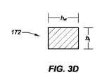
図3Dは、本開示の様々な実施形態による、図3Aに示される外側基礎構造170の第1の外側アーム基礎構造172の線hhに沿った断面を示す。いくつかの実施形態では、線htによって規定される第1の外側アーム基礎構造172での厚みは、0.0045から0.0065インチの範囲であってもよい。いくつかの実施形態では、第1の外側アーム基礎構造172での厚みは、約0.006インチであってもよい。いくつかの実施形態では、線hwによって規定される第1の外側アーム基礎構造172での横方向の幅(例えば、長手軸b’b’を横断して延びる幅)は、0.0125から0.0135インチの範囲であってもよい。いくつかの実施形態では、第1の外側アーム基礎構造172での横方向の幅は、約0.013インチであってもよい。第2の外側アーム基礎構造174は、第1の外側アーム基礎構造172に関連して議論されたように、同様の構造を有してもよい。
FIG. 3D illustrates a cross section of the first
図4は、本開示の様々な実施形態による、内側フレーム固定部136と外側フレーム固定部188を連結した状態の図2Aに示される内側基礎構造120及び図3Aに示される外側基礎構造170を示す。内側基礎構造120と外側基礎構造170は、図2Aから図3Dに関連して既に議論された特徴を含む。図示されるように、内側フレーム固定部136は、外側フレーム固定部188と連結して示される。一例では、内側フレーム固定タブ138−1、138−2、140−1、140−2は、固定溝196−1、196−2、198−1、198−2内に配置され、外側フレーム固定タブ192−1、192−2、194−1、194−2に隣接する。これにより、内側フレーム固定部136と外側フレーム固定部188との間に連結嵌合ができる。いくつかの実施形態では、連結嵌合は、外側基礎構造170に対する内側基礎構造120の長手方向の動きを抑制することができる。4個の内側フレーム固定タブ138−1、138−2、140−1、140−2及び4個の外側フレーム固定タブ192−1、192−2、194−1、194−2が図示されているけれども、4個よりも多い又は少ない内側及び/又は外側フレーム固定タブが、内側及び外側基礎構造に含まれてもよい。いくつかの実施形態では、内側フレーム固定部136の最上面が外側フレーム固定部188の最上面と同一平面上にあり、内側フレーム固定部136の最下面が外側フレーム固定部188の最下面と同一平面上にあるように、内側フレーム固定部136が、外側フレーム固定部188内に配置されてもよい。
FIG. 4 illustrates the
いくつかの実施形態では、第1及び第2の外側移行基礎構造部180、181は、遠位から近位に向かう方向に低下する角度で形成されてもよく、ヘッド部182及びフレア状ヘッド部130を形成する基礎構造は、遠位から近位に向かう方向に増加する角度で形成されてもよい。これにより、シースを介した挿入及び取り出しが容易になり、また、内側基礎構造120及び/又は外側基礎構造170に配置される電極の製造中の容易さも増すことができる。例えば、組み立て中、電極は、基礎構造に渡って、近位から遠位に向かう方向にスライドされてもよい。外側移行基礎構造の角度により、基礎構造に渡って、電極を容易にスライドすることが可能である。
In some embodiments, the first and second
図5Aは、本開示の様々な実施形態による、内側フレーム固定部136と、外側フレーム固定部188と、連結部材212とが連結した状態の図2Aに示される内側基礎構造120及び図3Aに示される外側基礎構造170を示す。内側フレーム固定部136と外側フレーム固定部188との間に、間隙が示される。いくつかの実施形態では、連結部材212は、図示されるように、内側フレーム固定部136及び外側フレーム固定部188の遠位端に配置されてもよい。内側基礎構造120と外側基礎構造170は、連結部材212を通り、長手方向に延びていてもよい。
FIG. 5A illustrates the
一例では、連結部材212は、連結部材ヘッド部214と、取付部216と、を含んでもよく、ポリマー又は金属から形成されてもよい。いくつかの実施形態では、取付部216は、円筒形状を有してもよく、カテーテルシャフトの遠位端に挿入される大きさであってもよい。いくつかの実施形態では、接着剤が、カテーテルシャフトと取付部216との間に塗られてもよく、及び/又は機械的な連結部材が、カテーテルシャフトを取付部216に固定するために使用されてもよい。いくつかの実施形態では、一連の円周溝が、取付部216の円周に延びてもよい。円周溝は、連結部材212をカテーテルシャフトに連結するときに、接着剤が集まる領域を提供してもよい。いくつかの実施形態では、連結部材ヘッド部214は、取付部216よりも大きく、カテーテルシャフトの外径に等しくてもよい外径を有してもよい。ヘッド部214の遠位端は、図示されるように、非侵襲的なチップを形成するドーム形状であってもよい。
In one example, the
図5Bは、本開示の様々な実施形態による、連結された内側フレーム固定部136及び外側フレーム固定部188の周りに管220、222を配置した状態の、図5Aに示される内側基礎構造120及び外側基礎構造170を示す。いくつかの実施形態では、管220の第1の部分と管222の第2の部分とのそれぞれは、内側フレーム固定部136と外側フレーム固定部188の連結部の周りに配置されてもよい。管220、222の第1及び第2の部分内に配置される内側フレーム固定部136と外側フレーム固定部188の連結部は、透かして図示されている。一例では、管220の第1の部分及び管222の第2の部分は、内側フレーム固定部136と外側フレーム固定部188の連結部の横方向の幅と同一、又はそれより大きい内径を有してもよい。管220の第1の部分及び管222の第2の部分は、内側フレーム固定部136と外側フレーム固定部188の連結部が、管220、222の第1及び第2の部分のそれぞれの内腔に配置されるように、内側フレーム固定部136と外側フレーム固定部188の連結部の近位部に渡って、縦方向にスライドされてもよい。
FIG. 5B illustrates the
管220、222の第1及び第2の部分が、内側フレーム固定部136と外側フレーム固定部188の連結部の近位部に渡って延びるように図示されているけれども、管220、222の第1及び第2の部分は、さらに遠位に延びてもよい。例えば、管220、222の第1及び第2の部分は、連結部材212の近位端に延びてもよい。いくつかの実施形態では、管220、222の第1及び第2の部分の内腔は、内側フレーム固定部136と外側フレーム固定部188の連結部を固定するために、接着剤で満たされてもよい。いくつかの実施形態では、管220、222の第1及び第2の部分は、熱収縮管であってよく、内側フレーム固定部136と外側フレーム固定部188の連結部を固定するために熱を加えられ、収縮されてもよい。
Although the first and second portions of the
図6は、本開示の様々な実施形態による、曲げられた高密度電極マッピングカテーテルの等角上面図である。いくつかの実施形態では、高密度電極マッピングカテーテルは、カテーテルシャフト228の遠位端に配置され、微小電極234の可撓性アレイを形成する可撓性チップ部232を含む。微小電極234のこの平面アレイ(又は「パドル」構造)は、並んで長手方向に延びる4個のアーム236、238、240、242を備え、4個のアーム236、238、240、242は、微小電極234が配置される可撓性枠組みを形成してもよい。4個の微小電極保持アームは、第1の外側アーム236と、第2の外側アーム242と、第1の内側アーム238と、第2の内側アーム240と、を備える。これらのアームは、互いに横方向に離れていてもよい。可撓性チップ232の内側部分は、フレア状ヘッド部244を含んでもよく、可撓性チップ232の外側部分は、ヘッド部246を含んでもよい。既に議論されたように、第1の外側アーム236及び第2の外側アーム242は、外側基礎構造を含んでもよく、第1の内側アーム238及び第2の内側アーム240は、内側基礎構造を含んでもよい。本明細書で既に議論されたように、第1及び第2の内側アーム238、240及びフレア状ヘッド部244は、長方形断面を含む要素から形成される第1及び第2の内側アーム基礎構造を含んでもよく、第1及び第2の外側アーム236、242及びヘッド部246は、長方形断面を含む要素から形成される第1及び第2の外側アーム基礎構造を含んでもよい。いくつかの実施形態では、可撓性チップ部232は、第1の外側移行部248と、第2の外側移行部254と、を含んでもよい。いくつかの実施形態では、可撓性チップ部232は、第1の内側移行部250と、第2の内側移行部252と、を含んでもよい。
FIG. 6 is an isometric top view of a bent high-density electrode mapping catheter, according to various embodiments of the present disclosure. In some embodiments, the high density electrode mapping catheter includes a
いくつかの実施形態では、図2Aから図3Dに関連して既に議論され、図示されているように、フレア状ヘッド部244を形成する基礎構造は、内側アーム238、240を形成する基礎構造に対して、減少した断面の幅を有してもよい。さらに、ヘッド部246を形成する基礎構造は、外側アーム236、242を形成する基礎構造に対して、減少した断面の幅を有してもよい。フレア状ヘッド部244及びヘッド部246を形成する基礎構造のこのような減少した断面の幅は、ヘッド部244、246の弾力性を高め、ヘッド部244、246を心臓組織に対して損傷が少ないものにする。例えば、減少した断面の幅のおかげで、ヘッド部は、高い柔軟性を有することができ、ヘッド部244、246を曲げるために必要な力の量を減らすことが可能であり、非侵襲的な設計を提供する。
In some embodiments, as already discussed and illustrated in connection with FIGS. 2A-3D, the substructure forming the flared
いくつかの実施形態では、図2Aから図3Dに関連して既に議論され、図示されているように、第1の外側アーム236と、第2の外側アーム242と、第1の外側移行部248と、第2の外側移行部254とは、ヘッド部246を形成する基礎構造に対して増加した断面の幅を有する基礎構造から形成されてもよい。さらに、第1の内側アーム238と、第2の内側アーム240と、第1の内側移行部250と、第2の内側移行部252とは、フレア状ヘッド部244を形成する基礎構造に対して増加した断面の幅を有する基礎構造から形成されてもよい。いくつかの実施形態では、内側及び外側移行部、並びに内側及び外側アームを形成する基礎構造の増加した断面の幅は、フレア状ヘッド部244及びヘッド部246の近位に位置する可撓性チップ部232のより緩やかな曲がりを提供することができる。より緩やかな曲がりは、内側及び外側アーム及び/又は内側及び外側移行部に配置されるすべての電極と一様な(例えば、均一な)心臓組織接触をもたらす点で有益となり得る。
In some embodiments, a first
さらに、可撓性チップ部232の各要素を形成する基礎構造が長方形断面を含むため、様々な解剖の状況に関連して直面する様々な横方向の力(例えば、つまむ)が可撓性チップ部に加えられるとき、可撓性チップ部232に配置される微小電極の各々の間の横方向の間隔を維持することができる。例えば、図1をさらに参照すると、横方向の力が矢印112−1、112−2の方向に可撓性チップ部110に加えられるときでさえ、電極の間隔は、維持される。内側及び外側アームを形成する基礎構造が管状の材料からなるいくつかのアプローチでは、内側及び/又は外側アームに横方向の力が加えられると、アームは、長手軸aaに向かって内側に曲がり得る。例えば、外側アーム103、106が管状の基礎構造を含むとすると、外側アーム103、106は、矢印112−1、112−2の方向に力が加えられることに応じて、長手軸に向かって及び内側アーム104、105に向かって、横方向に内側へ押されるだろう。これにより、外側アームに配置された微小電極と内側アームに配置された微小電極との間隔が減少してしまい、微小電極間の干渉をもたらす。しかしながら、本開示の実施形態は、内側アームと外側アームとの間及び内側アームと外側アームに配置される微小電極の間に、間隔を維持することができる。
In addition, because the underlying structure forming each element of the
一例では、本明細書に議論されるように、また図2Aから3Dに関連して議論されるように、内側アーム104、105及び外側アーム103、106を形成する基礎構造は、長方形断面を有してもよい。例えば、内側アーム104、105及び外側アーム103、106を形成する基礎構造は、ヘッド部を形成する基礎構造の横方向の幅に対して増加した横方向の幅を有してもよい。加えて、横方向の幅の寸法は、内側アーム104、105及び外側アーム103、106を形成する基礎構造の厚みの寸法より大きくてもよい。これにより、外側アーム103、106が長手軸aaに向かって内側へ曲がることが防止でき、したがって、微小電極102の間の横方向の間隔を維持することができる。例えば、矢印112−1、112−2の方向における横方向の力の存在下で、第1の外側アーム103に配置される第1の微小電極102−1と第1の内側アーム104に配置される第3の微小電極102−3との間で横方向の間隔が維持される。同様に、矢印112−1、112−2の方向における横方向の力の存在下で、第1の外側アーム103に配置される第2の微小電極102−2と第1の内側アーム104に配置される第4の微小電極102−4との間で横方向の間隔が維持される。
In one example, as discussed herein, and as discussed in connection with FIGS. 2A-3D, the substructure forming the
横方向に曲がる代わりに、図7Aから図7Dに関連してさらに議論されるように、内側基礎構造及び/又は外側基礎構造は、上向きに又は下向きに曲がってもよく、それによって電極が電極に接触することを回避する。図7Aは、本開示の様々な実施形態による、第1の曲げ状態262−1及び第2の曲げ状態262−2における高密度電極マッピングカテーテル260の正面図を示す。高密度電極マッピングカテーテル260は、外側基礎構造から形成される外側部分264を含む。本明細書に議論されるように、外側基礎構造は、長方形断面を有する要素から形成されてもよい。高密度電極マッピングカテーテル260は、内側部分280(図7B及び図7Dに示される)を外側部分264と連結する遠位カプラー268と、カテーテルシャフト282(図7B及び図7Dに示される)の遠位端に配置される連結部材266を含んでもよい。図示されるように、外側部分264に加えられる横方向の力の量がゼロであるとき、外側部分264の基礎構造は、高密度電極マッピングカテーテル260の長手軸に対して横方向に延びる、第1の曲げ状態262−1(例えば、自然な曲げ状態)であってもよい。しかしながら、横方向の力が矢印270−1、270−2の方向に外側部分264に加えられると、外側部分は、透かして図示されるように、第2の曲げ状態262−2へ上向きに曲がってもよい。したがって、外側部分264は、高密度電極マッピングカテーテル260の長手軸に向かって内側へ横方向に曲がるよりも、第2の曲げ状態262−2へと上向きに曲がってもよい。
Instead of bending in the lateral direction, the inner and / or outer substructure may bend upward or downward, as discussed further in connection with FIGS. 7A-7D, such that the electrode is coupled to the electrode. Avoid contact. FIG. 7A illustrates a front view of a high-density
図2Bは、本開示の様々な実施形態による、図7Aの第2の曲げ状態262−2にある高密度電極マッピングカテーテル260の斜視図を示す。高密度電極マッピングカテーテル260は、図7Aに関連して議論された特徴、例えば、高密度電極マッピングカテーテル260が、外側部分264と、内側部分280と、遠位カプラー268と、連結部材266と、カテーテルシャフト282とを含むこと、を含む。図示されるように、外側部分264及び内側部分280は、高密度電極マッピングカテーテル260(例えば、外側部分264及び/又は内側部分280)に横方向の力が加えられることに応じて、上向きに曲げられてもよい。一例では、高密度電極マッピングカテーテル260の第1の外側アーム282と第2の外側アーム288とを形成する基礎構造、及び第1の内側アーム284と第2の内側アーム286とを形成する基礎構造が、長方形断面を有する(例えば、厚みに対して増加した横方向の幅を有する)ため、第1及び第2の外側アーム282、288は、高密度電極マッピングカテーテル260の長手軸に向かって内側へ横方向に曲がる代わりに、上向きに曲がってもよい。
FIG. 2B shows a perspective view of the dense
図7Cは、本開示の実施形態による、第1の曲げ状態262−1及び第3の曲げ状態262−3における図7A及び図7Bに示される高密度電極マッピングカテーテル260の正面図である。高密度電極マッピングカテーテル260は、外側基礎構造から形成される外側部分264と、カテーテルシャフト282の遠位端に配置される連結部材266(図7B及び図7Dに示される)と、内側部分280(図7B及び図7Dに示される)を外側部分264と連結する遠位カプラー268と、を含む。図示されるように、外側部分264に加えられる横方向の力の量がゼロであるとき、外側部分264の基礎構造は、高密度電極マッピングカテーテル260の長手軸に対して横方向に延びる、第1の曲げ状態262−1(例えば、自然な曲げ状態)であってもよい。しかしながら、横方向の力が矢印270−1’、270−2’の方向に外側部分264に加えられると、外側部分264は、透かして図示されるように、第3の曲げ状態262−3へ下向きに曲がってもよい。したがって、外側部分264は、高密度電極マッピングカテーテル260の長手軸に向かって内側へ横方向に曲がるよりも、第3の曲げ状態262−3へ下向きに曲がってもよい。いくつかの実施形態では、高密度電極マッピングカテーテル260の外側部分264又は内側部分280が、下向きに曲がるのか上向きに曲がるのかに関連する決定因子は、横方向の力が外側部分264及び/又は内側部分280に加えられる角度に関連付けられてもよい。
FIG. 7C is a front view of the high density
図7Dは、本開示の様々な実施形態による、図7Cの第3の曲げ状態262−3における高密度電極マッピングカテーテル260の斜視図を示す。高密度電極マッピングカテーテル260は、図7Cに関連して議論された特徴、例えば、高密度電極マッピングカテーテル260が、外側部分264と、内側部分280と、遠位カプラー268と、連結部材266と、カテーテルシャフト282とを含むこと、を含む。図示されるように、外側部分264及び内側部分280は、高密度電極マッピングカテーテル260(例えば、外側部分264及び/又は内側部分280)に横方向の力が加えられることに応じて、下向きに曲げられてもよい。一例では、高密度電極マッピングカテーテル260の第1の外側アーム282及び第2の外側アーム288を形成する基礎構造、及び第1の内側アーム284及び第2の内側アーム286を形成する基礎構造が、長方形断面を有する(例えば、厚みに対する増加した横方向の幅を有する)ため、第1及び第2の外側アーム282、288は、高密度電極マッピングカテーテル260の長手軸に向かって内側へ横方向に曲がる代わりに、下向きに曲がってもよい。これにより、内側及び外側アームに配置される微小電極の間隔を維持することができる。
FIG. 7D illustrates a perspective view of the dense
図8は、本開示の様々な実施形態による、折りたたみ状態における可撓性チップ部304を有する高密度電極マッピングカテーテル300の上面図である。いくつかの実施形態では、高密度電極マッピングカテーテル300は、カテーテルシャフト302を含んでもよい。カテーテルシャフト302は、近位端と遠位端とを含んでもよい。遠位端は、カテーテルシャフト302の遠位端を可撓性チップ部304(例えば、平面アレイ)の近位端に連結する連結部材306を含んでもよい。可撓性チップ部304は、第1の外側アーム308と、第2の外側アーム314と、ヘッド部318と、を含む外側部分を含んでもよく、第1の内側アーム310と、第2の内側アーム312と、フレア状ヘッド部316と、を含む内側部分も含んでもよい。いくつかの実施形態では、ヘッド部318とフレア状ヘッド部316とは、遠位カプラー320を介して、それぞれの遠位端で連結されてもよい。
FIG. 8 is a top view of a high density
図示されるように、可撓性チップ部304は、格納された状態である。一例では、可撓性チップ部304が体内への導入のためにシース内に格納されているとき、柔軟なチップ部304は、そのような状態であってもよい。シースに可撓性チップ部304を導入する際に、可撓性チップ部304の外側部分及び内側部分は、高密度電極マッピングカテーテル300の長手軸に向かって横方向に圧縮されてもよい。例えば、可撓性チップ部304の外側部分及び内側部分は、シースの内壁によって横方向に圧縮されてもよい。いくつかの実施形態では、内側部分及び外側部分が、可撓性チップ部304の長手軸に向かって横方向に圧縮される際に、内側部分のフレア状ヘッド部316は、真っ直ぐにされてもよい。フレア状ヘッド部316を有さないいくつかのアプローチでは、内側部分及び外側部分が横方向に圧縮されると、可撓性チップ部304の遠位端に、フックが形成されてもよい。本開示の実施形態は、内側部分及び外側部分が横方向に圧縮されるときに伸ばされる弛み部を提供するフレア状ヘッド部316を含んでもよい。例えば、シースを介する挿入及び/又は取り出し中に折りたたまれている際、フレア状遠位ヘッド(例えば、スペード形状部)は、外側のフレームの全長と一致するのに必要な余分な長さを補ってもよく、フックが形成されることを防ぐことができる。
As shown, the
本明細書では、様々な装置、システム、及び/又は方法の実施形態が説明される。本開示の追加の様態は、ここに添付される付録Aの内容のレビューに基づいて明らかとなるだろう。本明細書で説明され、添付図面に示された実施形態の全体的な構造、機能、製造、及び使用の完全な理解を提供するために、多数の特定の詳細が示される。しかしながら、実施形態が、そのような特定の詳細なしで実践され得ることが、当業者によって理解されよう。他の場合には、本明細書で説明される実施形態を不明瞭にしないように、周知の動作、構成要素、及び要素は、詳細には説明されなかった。当業者は、本明細書で説明され図示された実施形態が、非限定的な例であることを理解し、したがって、本明細書で開示される特定の構造的詳細及び機能的詳細は、代表的なものであって、必ずしも添付の特許請求の範囲のみによって定義される実施形態の範囲を限定しないものであることが、了解され得る。 Described herein are various device, system, and / or method embodiments. Additional aspects of the present disclosure will become apparent upon review of the contents of Appendix A attached hereto. Numerous specific details are set forth in order to provide a thorough understanding of the overall structure, function, manufacture, and use of the embodiments described herein and illustrated in the accompanying drawings. However, it will be understood by those skilled in the art that embodiments may be practiced without such specific details. In other instances, well-known operations, components, and elements have not been described in detail so as not to obscure the embodiments described herein. Those skilled in the art will understand that the embodiments described and illustrated herein are non-limiting examples, and therefore certain structural and functional details disclosed herein may be It should be understood that the invention is not intended to limit the scope of the embodiments, which are necessarily defined only by the appended claims.
本明細書全体を通しての「様々な実施形態」、「いくつかの実施形態」、「一実施形態」、もしくは「実施形態」などへの言及は、実施形態に関連して説明される特定の特徴、構造、又は特性が、少なくとも一つの実施形態に含まれることを意味する。したがって、本明細書全体を通して所々で出現する「様々な実施形態で」、「いくつかの実施形態で」、「一実施形態で」、もしくは「実施形態で」などの句は、必ずしもすべて同一の実施形態に言及するものではない。さらに、特定の特徴、構造、又は特性が、一つ又は複数の実施形態において任意の適切な形で組み合わされ得る。したがって、組合せが非論理的又は機能不能ではない限り、一実施形態に関連して図示され又は説明される特定の特徴、構造、又は特性は、全体的に又は部分的に、限定されることなく、一つ又は複数の他の実施形態の特徴、構造、又は特性と組み合わされてよい。 Throughout this specification, references to “various embodiments,” “some embodiments,” “one embodiment,” or “embodiments” refer to particular features described in connection with the embodiments. , Structure, or characteristic is included in at least one embodiment. Thus, phrases such as “in various embodiments,” “in some embodiments,” “in one embodiment,” or “in embodiments” that appear in various places throughout this specification are not necessarily all the same. It does not refer to the embodiments. Furthermore, the particular features, structures, or characteristics may be combined in any suitable manner in one or more embodiments. Thus, unless a combination is illogical or inoperable, the particular features, structures, or characteristics shown or described in connection with one embodiment may be limited in whole or in part. Rather, it may be combined with features, structures, or characteristics of one or more other embodiments.
本明細書全体を通して、「近位」及び「遠位」という用語が、患者を治療するのに使用される器具の一端を操作する臨床医を基準にして使用されてもよいことを了解されたい。「近位」という用語は、器具のうちで臨床医に最も近い部分を指し、「遠位」という用語は、臨床医から最も遠くに配置された部分を指す。簡潔さ及び明瞭さのために、「垂直」、「水平」、「上」、及び「下」などの空間的用語が、図示の実施形態に関して本明細書で使用される場合があることをさらに了解されたい。しかしながら、手術器具は、様々な方位及び位置で使用されてよく、これらの用語は、限定的、絶対的であることを意図したものではない。 It is to be understood that throughout this specification, the terms "proximal" and "distal" may be used with reference to a clinician operating one end of an instrument used to treat a patient. . The term "proximal" refers to the portion of the device that is closest to the clinician, and the term "distal" refers to the portion located furthest from the clinician. It is further noted that for brevity and clarity, spatial terms such as "vertical", "horizontal", "above", and "below" may be used herein with respect to the illustrated embodiments. I want to understand. However, surgical instruments may be used in a variety of orientations and positions, and these terms are not intended to be limiting or absolute.
高密度電極マッピングカテーテルの少なくとも一つの実施形態が、ある度合の詳細を伴って上述されたが、当業者は、本開示の趣旨又は範囲から逸脱せずに、開示された実施形態に関して多数の変更を行うことができる。すべての方向に関する言及(例えば、上側、下側、上向き、下向き、左、右、左向き、右向き、最上部、最下部、上、下、垂直、水平、時計回り、及び反時計回り)は、本開示の読み手による理解を助けるために識別目的のために使用されるのみであって、特にデバイスの位置、方位、又は使用に関する限定を創造するものではない。接合に関する言及(例えば、固定される、取り付けられる、結合される、接続されるなど)は、広義に解釈されるべきであり、要素間の接続及び要素間の相対移動との間に中間部材を含んでもよい。このように、接合に関する言及は、必ずしも、二つの要素が直接接続され、互いに固定された関係にあることを暗示するものではない。上記の説明に含まれるか又は添付図面に示されたすべての事項が、例示的であるのみであって、限定的なものではないものと解釈されなければならないことが意図される。詳細又は構造の変更が、添付の特許請求の範囲で定義される本開示の趣旨から逸脱せずに行われてもよい。 While at least one embodiment of a high density electrode mapping catheter has been described above with some degree of detail, those skilled in the art will appreciate that numerous modifications may be made to the disclosed embodiment without departing from the spirit or scope of the present disclosure. It can be performed. References to all directions (eg, up, down, up, down, left, right, left, right, top, bottom, up, down, vertical, horizontal, clockwise, and counterclockwise) It is only used for identification purposes to aid the reader in understanding the disclosure and does not create any particular limitations on the location, orientation, or use of the device. References to joining (e.g., fixed, attached, joined, connected, etc.) should be construed broadly, and refer to intermediate members between connection between elements and relative movement between elements. May be included. Thus, reference to a join does not necessarily imply that the two elements are directly connected and in fixed relation to each other. It is intended that all matter contained in the above description or shown in the accompanying drawings shall be interpreted as illustrative only and not limiting. Changes in detail or structure may be made without departing from the spirit of the disclosure as defined in the appended claims.
参照によって本明細書に組み込まれると言われるすべての特許、公告、又は他の開示資料は、全体的に又は部分的に、組み込まれた資料が本開示で示される既存の定義、言明、又は他の開示材料と対立しない範囲に限って本明細書に組み込まれる。したがって、必要な範囲まで、本明細書で明示的に示される開示は、参照によって本明細書に組み込まれるいかなる対立する資料にも取って代わる。参照によって本明細書に組み込まれると言われるが、本明細書で示される既存の定義、言明、又は他の開示材料と対立するいかなる資料又はその一部は、組み込まれる資料と既存の開示材料との間に対立が生じない範囲に限って組み込まれる。
以下の項目は、国際出願時の特許請求の範囲に記載の要素である。
(項目1)
可撓性カテーテルチップであって、
チップ長手軸を規定する内側基礎構造であって、第1の長方形断面を含む第1の連続要素から形成される前記内側基礎構造と、
前記チップ長手軸に沿って延びる外側基礎構造であって、第2の長方形断面を含む第2の連続要素から形成される前記外側基礎構造と、を備える、可撓性カテーテルチップ。
(項目2)
前記内側基礎構造は、
前記チップ長手軸に沿って延びる第1の近位内側取付アーム及び第2の近位内側取付アームを含む、請求項1に記載の可撓性カテーテルチップ。
(項目3)
前記内側基礎構造は、
前記第1の近位内側取付アームから遠位に延びる第1の内側アーム基礎構造と、
前記第2の近位内側取付アームから遠位に延びる第2の内側アーム基礎構造と、を含む、請求項2に記載の可撓性カテーテルチップ。
(項目4)
前記内側基礎構造は、前記第1及び前記第2の内側基礎構造の遠位端に連結されるフレア状ヘッド部を含む、請求項3に記載の可撓性カテーテルチップ。
(項目5)
前記外側基礎構造は、
前記チップ長手軸に沿って延びる第1の近位外側取付アーム及び第2の近位外側取付アームを含む、請求項2に記載の可撓性カテーテルチップ。
(項目6)
前記第1の近位内側取付アーム及び前記第1の近位外側取付アームの対向する面は、フレーム固定の第1のセットを含み、
前記第2の近位内側取付アーム及び前記第2の近位外側取付アームの対向する面は、前記フレーム固定の第1のセットに対応するフレーム固定の第2のセットを含む、請求項5に記載の可撓性カテーテルチップ。
(項目7)
前記フレーム固定の第1のセット及び前記フレーム固定の第2のセットは、互いに連結するように構成される、請求項6に記載の可撓性カテーテルチップ。
(項目8)
前記フレーム固定の第1のセットは、前記第1の近位内側取付アーム及び前記第1の近位外側取付アームの前記対向する面から延びる複数の連結タブを含み、
前記フレーム固定の第2のセットは、前記第2の近位内側取付アーム及び前記第2の近位外側取付アームの前記対向する面から延びる複数の連結タブを含む、請求項7に記載の可撓性カテーテルチップ。
(項目9)
前記複数の連結タブは、前記第1の近位内側取付アームと前記第1の近位外側取付アームとの間、及び、前記第2の近位内側取付アームと前記第2の近位外側取付アームとの間で、長手方向に交互に現れる、請求項8に記載の可撓性カテーテルチップ。
(項目10)
前記内側基礎構造の遠位端は、前記外側基礎構造の遠位端に、遠位カプラーで連結される、請求項1に記載の可撓性カテーテルチップ。
(項目11)
前記内側基礎構造及び前記外側基礎構造は、ニチノールから形成される、請求項1に記載の可撓性カテーテルチップ。
(項目12)
一体型電極構造であって、
近位端及び遠位端を備えるカテーテルシャフトであって、カテーテルシャフト長手軸を規定する前記カテーテルシャフトと、
前記カテーテルシャフトの前記遠位端に隣接して位置される可撓性チップ部であって、可撓性枠組みを備える前記可撓性チップ部と、を備え、
前記可撓性枠組みは、
前記シャフト長手軸に沿って延びる第1の連続要素であって、第1の長方形断面を含む前記第1の連続要素を含む内側基礎構造と、
前記シャフト長手軸に沿って延びる第2の連続要素であって、第2の長方形断面を含む前記第2の連続要素を含む外側基礎構造と、
前記内側基礎構造の遠位端と前記外側基礎構造の遠位端とを連結する遠位カプラーと、を含む、一体型電極構造。
(項目13)
前記内側基礎構造の近位内側部分及び前記外側基礎構造の近位外側部分のそれぞれは、フレーム固定部を含む、請求項12に記載の一体型電極構造。
(項目14)
前記フレーム固定部は、さね継ぎ構造(tongue and groove structure)を含む、請求項13に記載の一体型電極構造。
(項目15)
複数の電極は、前記内側基礎構造及び前記外側基礎構造に配置される、請求項12に記載の一体型電極構造。
(項目16)
医療装置であって、
近位端及び遠位端を備えるカテーテルシャフトであって、カテーテルシャフト長手軸を規定する前記カテーテルシャフトと、
可撓性枠組みを備える可撓性チップ部と、を備え、
前記可撓性枠組みは、
前記カテーテルシャフトの前記遠位端に取り付けられる一対の近位内側取付アームを含む内側基礎構造と、
前記カテーテルシャフトの前記遠位端に取り付けられる一対の近位外側取付アームを含む外側基礎構造と、を含み、
前記近位内側取付アームのそれぞれは、内側フレーム固定部を含み、
前記近位外側取付アームのそれぞれは、前記内側フレーム固定部に対応する外側フレーム固定部を含む、医療装置。
(項目17)
前記内側基礎構造は、前記一対の近位内側取付アームから遠位に延びる一対の内側アームと、
前記一対の内側アームの遠位端に連結されるフレア状ヘッド部と、を含む請求項16に記載の医療装置。
(項目18)
前記外側基礎構造は、前記一対の近位外側取付アームから遠位に延びる一対の外側アームと、
前記一対の外側アームの遠位端に連結されるヘッド部と、を含む請求項17に記載の医療装置。
(項目19)
前記フレア状ヘッド部及び前記ヘッド部は、遠位カプラーを介して連結される、請求項18に記載の医療装置。
(項目20)
前記ヘッド部を形成する前記基礎構造の長手方向の幅は、前記外側アームのそれぞれを形成する前記基礎構造の横方向の幅より小さく、
前記フレア状ヘッド部を形成する前記基礎構造の長手方向の幅は、前記内側アームのそれぞれを形成する前記基礎構造のそれぞれの横方向の幅より小さい、請求項18に記載の医療装置。
All patents, publications, or other disclosure material that are said to be incorporated by reference herein, in whole or in part, are subject to existing definitions, statements, or other statements in which the incorporated material is set forth in this disclosure. To the extent that they do not conflict with the disclosed materials. Thus, to the extent necessary, the disclosure as explicitly set forth herein supersedes any conflicting material incorporated herein by reference. Any material, or part thereof, which is said to be incorporated herein by reference, but which conflicts with the existing definitions, statements, or other disclosed materials set forth herein, is incorporated by reference. Are included only to the extent that conflict does not occur.
The following items are the elements described in the claims at the time of international application.
(Item 1)
A flexible catheter tip,
An inner substructure defining a chip longitudinal axis, said inner substructure being formed from a first continuous element including a first rectangular cross section;
A flexible catheter tip comprising: an outer substructure extending along the tip longitudinal axis, the outer substructure being formed from a second continuous element including a second rectangular cross section.
(Item 2)
The inner substructure includes:
The flexible catheter tip of claim 1, comprising a first proximal inner mounting arm and a second proximal inner mounting arm extending along the tip longitudinal axis.
(Item 3)
The inner substructure includes:
A first inner arm substructure extending distally from the first proximal inner mounting arm;
A second inner arm substructure extending distally from the second proximal inner mounting arm.
(Item 4)
4. The flexible catheter tip of claim 3, wherein the inner substructure includes a flared head connected to distal ends of the first and second inner substructures.
(Item 5)
The outer substructure is
3. The flexible catheter tip of claim 2, including a first proximal outer mounting arm and a second proximal outer mounting arm extending along the tip longitudinal axis.
(Item 6)
Opposing surfaces of the first proximal inner mounting arm and the first proximal outer mounting arm include a first set of frame anchors,
6. The opposing surface of the second proximal inner mounting arm and the second proximal outer mounting arm includes a second set of frame fixings corresponding to the first set of frame fixings. A flexible catheter tip as described.
(Item 7)
7. The flexible catheter tip of claim 6, wherein the first set of frame anchors and the second set of frame anchors are configured to couple to one another.
(Item 8)
A first set of frame fixings including a plurality of connecting tabs extending from the opposing surfaces of the first proximal inner mounting arm and the first proximal outer mounting arm;
The method of claim 7, wherein the second set of frame anchors includes a plurality of connecting tabs extending from the opposing surfaces of the second proximal inner mounting arm and the second proximal outer mounting arm. Flexible catheter tip.
(Item 9)
The plurality of connection tabs are between the first proximal inner mounting arm and the first proximal outer mounting arm and between the second proximal inner mounting arm and the second proximal outer mounting arm. 9. The flexible catheter tip of claim 8, wherein the flexible catheter tip alternates longitudinally with the arm.
(Item 10)
The flexible catheter tip of claim 1, wherein a distal end of the inner substructure is connected to a distal end of the outer substructure with a distal coupler.
(Item 11)
The flexible catheter tip according to claim 1, wherein the inner substructure and the outer substructure are formed from Nitinol.
(Item 12)
An integrated electrode structure,
A catheter shaft having a proximal end and a distal end, said catheter shaft defining a catheter shaft longitudinal axis;
A flexible tip positioned adjacent to the distal end of the catheter shaft, the flexible tip comprising a flexible framework.
Said flexible framework,
An inner substructure including a first continuous element extending along the longitudinal axis of the shaft, the first continuous element including a first rectangular cross-section;
A second continuous element extending along the longitudinal axis of the shaft, the outer substructure including the second continuous element including a second rectangular cross-section;
An integrated electrode structure, comprising: a distal coupler connecting a distal end of the inner substructure and a distal end of the outer substructure.
(Item 13)
13. The integrated electrode structure of claim 12, wherein each of a proximal inner portion of the inner substructure and a proximal outer portion of the outer substructure include a frame fixture.
(Item 14)
14. The integrated electrode structure according to claim 13, wherein the frame fixing part includes a tongue and groove structure.
(Item 15)
13. The integrated electrode structure according to claim 12, wherein a plurality of electrodes are disposed on the inner substructure and the outer substructure.
(Item 16)
A medical device,
A catheter shaft having a proximal end and a distal end, said catheter shaft defining a catheter shaft longitudinal axis;
A flexible tip portion comprising a flexible framework,
Said flexible framework,
An inner substructure including a pair of proximal inner mounting arms attached to the distal end of the catheter shaft;
An outer substructure that includes a pair of proximal outer mounting arms attached to the distal end of the catheter shaft.
Each of the proximal inner mounting arms includes an inner frame anchor,
The medical device, wherein each of the proximal outer mounting arms includes an outer frame fastener corresponding to the inner frame fastener.
(Item 17)
A pair of inner arms extending distally from the pair of proximal inner mounting arms;
17. The medical device of claim 16, including a flared head coupled to distal ends of the pair of inner arms.
(Item 18)
The outer substructure includes a pair of outer arms extending distally from the pair of proximal outer mounting arms;
The medical device according to claim 17, further comprising: a head connected to distal ends of the pair of outer arms.
(Item 19)
19. The medical device according to claim 18, wherein the flared head and the head are connected via a distal coupler.
(Item 20)
A longitudinal width of the basic structure forming the head portion is smaller than a lateral width of the basic structure forming each of the outer arms;
19. The medical device of claim 18, wherein a longitudinal width of the base structure forming the flared head portion is less than a lateral width of each of the base structures forming each of the inner arms.
Claims (16)
チップ長手軸を規定する内側基礎構造であって、第1の長方形断面を含む第1の連続要素から形成される前記内側基礎構造と、
前記チップ長手軸に沿って延びる外側基礎構造であって、第2の長方形断面を含む第2の連続要素から形成される前記外側基礎構造と、を備え、
前記内側基礎構造は、
第1の近位内側取付アーム及び第2の近位内側取付アームを含み、
前記外側基礎構造は、
第1の近位外側取付アーム及び第2の近位外側取付アームを含み、
前記第1の近位内側取付アーム及び前記第1の近位外側取付アームの対向する面は、フレーム固定の第1のセットを含み、
前記第2の近位内側取付アーム及び前記第2の近位外側取付アームの対向する面は、前記フレーム固定の第1のセットに対応するフレーム固定の第2のセットを含む、可撓性カテーテルチップ。 A flexible catheter tip,
An inner substructure defining a chip longitudinal axis, said inner substructure being formed from a first continuous element including a first rectangular cross section;
An outer substructure extending along the chip longitudinal axis, wherein the outer substructure is formed from a second continuous element that includes a second rectangular cross section .
The inner substructure includes:
A first proximal inner mounting arm and a second proximal inner mounting arm;
The outer substructure is
A first proximal outer mounting arm and a second proximal outer mounting arm;
Opposing surfaces of the first proximal inner mounting arm and the first proximal outer mounting arm include a first set of frame anchors,
The flexible catheter , wherein opposing faces of the second proximal inner mounting arm and the second proximal outer mounting arm include a second set of frame fixation corresponding to the first set of frame fixation. Chips.
前記第1の近位内側取付アームから遠位に延びる第1の内側アーム基礎構造と、
前記第2の近位内側取付アームから遠位に延びる第2の内側アーム基礎構造と、を含む、請求項1に記載の可撓性カテーテルチップ。 The inner substructure includes:
A first inner arm substructure extending distally from the first proximal inner mounting arm;
The flexible catheter tip of claim 1 , comprising: a second inner arm substructure extending distally from the second proximal inner mounting arm.
前記フレーム固定の第2のセットは、前記第2の近位内側取付アーム及び前記第2の近位外側取付アームの前記対向する面から延びる複数の連結タブを含む、請求項4に記載の可撓性カテーテルチップ。 A first set of frame fixings including a plurality of connecting tabs extending from the opposing surfaces of the first proximal inner mounting arm and the first proximal outer mounting arm;
Second set of frame fixing comprises a plurality connecting tabs extending from the opposing surfaces of the second proximal inner mounting arm and the second proximal outer mounting arm, variable according to claim 4 Flexible catheter tip.
近位端及び遠位端を備えるカテーテルシャフトであって、カテーテルシャフト長手軸を規定する前記カテーテルシャフトと、
前記カテーテルシャフトの前記遠位端に隣接して位置される可撓性チップ部であって、可撓性枠組みを備える前記可撓性チップ部と、を備え、
前記可撓性枠組みは、
第1の長方形断面を含む第1の連続要素を含む内側基礎構造と、
第2の長方形断面を含む第2の連続要素を含む外側基礎構造と、を含み、
前記第1の連続要素は、
第1の近位内側取付アーム及び第2の近位内側取付アームを含み、
前記第2の連続要素は、
第1の近位外側取付アーム及び第2の近位外側取付アームを含み、
前記第1の近位内側取付アーム及び前記第1の近位外側取付アームの対向する面は、フレーム固定の第1のセットを含み、
前記第2の近位内側取付アーム及び前記第2の近位外側取付アームの対向する面は、前記フレーム固定の第1のセットに対応するフレーム固定の第2のセットを含む、一体型電極構造。 An integrated electrode structure,
A catheter shaft having a proximal end and a distal end, said catheter shaft defining a catheter shaft longitudinal axis;
A flexible tip positioned adjacent to the distal end of the catheter shaft, the flexible tip comprising a flexible framework.
Said flexible framework,
An inner substructure comprising including first continuous element first rectangular cross-section,
An outer base structure comprising including second continuous element second rectangular cross-section, only including,
The first continuous element comprises:
A first proximal inner mounting arm and a second proximal inner mounting arm;
The second continuous element is
A first proximal outer mounting arm and a second proximal outer mounting arm;
Opposing surfaces of the first proximal inner mounting arm and the first proximal outer mounting arm include a first set of frame anchors,
The opposing surfaces of the second proximal inner mounting arm and the second proximal outer mounting arm, said second set including a frame fixed corresponding to the first set of frame fixed, integral electrode Construction.
近位端及び遠位端を備えるカテーテルシャフトであって、カテーテルシャフト長手軸を規定する前記カテーテルシャフトと、
可撓性枠組みを備える可撓性チップ部と、を備え、
前記可撓性枠組みは、
第1の長方形断面を含む第1の連続要素から形成される内側基礎構造であって、前記カテーテルシャフトの前記遠位端に取り付けられる一対の近位内側取付アームを含む前記内側基礎構造と、
第2の長方形断面を含む第2の連続要素から形成される外側基礎構造であって、前記カテーテルシャフトの前記遠位端に取り付けられる一対の近位外側取付アームを含む前記外側基礎構造と、を含み、
前記一対の近位内側取付アームは、第1の近位内側取付アーム及び第2の近位内側取付アームを含み、
前記一対の近位外側取付アームは、第1の近位外側取付アーム及び第2の近位外側取付アームを含み、
前記第1の近位内側取付アーム及び前記第1の近位外側取付アームの対向する面は、フレーム固定の第1のセットを含み、
前記第2の近位内側取付アーム及び前記第2の近位外側取付アームの対向する面は、前記フレーム固定の第1のセットに対応するフレーム固定の第2のセットを含む、医療装置。 A medical device,
A catheter shaft having a proximal end and a distal end, said catheter shaft defining a catheter shaft longitudinal axis;
A flexible tip portion comprising a flexible framework,
Said flexible framework,
An inner basic structure formed from a first continuous element comprising a first rectangular cross-section, and the inner substructure comprising a pair of proximal inner mounting arm attached to said distal end of said catheter shaft,
An outer base structure which is formed from the second continuous element comprising a second rectangular cross-section, and said outer base structure including a pair of proximal outer mounting arm attached to the distal end of the catheter shaft, the Including
The pair of proximal inner mounting arms includes a first proximal inner mounting arm and a second proximal inner mounting arm ;
The pair of proximal outer mounting arms includes a first proximal outer mounting arm and a second proximal outer mounting arm .
Opposing surfaces of the first proximal inner mounting arm and the first proximal outer mounting arm include a first set of frame anchors,
The opposing surfaces of the second proximal inner mounting arm and the second proximal outer mounting arm, said frame fixed first second frame fixing that corresponds to a set of set including the medical device.
前記一対の内側アームの遠位端に連結されるフレア状ヘッド部と、を含む請求項12に記載の医療装置。 A pair of inner arms extending distally from the pair of proximal inner mounting arms;
The medical device of claim 1 2 comprising a flared head portion connected to a distal end of said pair of inner arms.
前記一対の外側アームの遠位端に連結されるヘッド部と、を含む請求項13に記載の医療装置。 The outer substructure includes a pair of outer arms extending distally from the pair of proximal outer mounting arms;
The medical device of claim 1 3 comprising a head portion connected to a distal end of said pair of outer arms.
前記フレア状ヘッド部を形成する前記内側基礎構造の長手方向の幅は、前記内側アームのそれぞれを形成する前記内側基礎構造のそれぞれの横方向の幅より小さい、請求項14または15に記載の医療装置。 A longitudinal width of the outer substructure forming the head portion is smaller than a lateral width of the outer substructure forming each of the outer arms;
Longitudinal width of the inner basic structure forming the flared head portion, each lateral width smaller than the inner substructure forming each of the inner arm, according to claim 1 4 or 1 5 Medical device.
Applications Claiming Priority (3)
| Application Number | Priority Date | Filing Date | Title |
|---|---|---|---|
| US201562244630P | 2015-10-21 | 2015-10-21 | |
| US62/244,630 | 2015-10-21 | ||
| PCT/US2016/058205 WO2017070531A1 (en) | 2015-10-21 | 2016-10-21 | High density electrode mapping catheter |
Related Child Applications (1)
| Application Number | Title | Priority Date | Filing Date |
|---|---|---|---|
| JP2019236327A Division JP6878560B2 (en) | 2015-10-21 | 2019-12-26 | High density electrode mapping catheter |
Publications (2)
| Publication Number | Publication Date |
|---|---|
| JP2018537151A JP2018537151A (en) | 2018-12-20 |
| JP6641003B2 true JP6641003B2 (en) | 2020-02-05 |
Family
ID=58558109
Family Applications (2)
| Application Number | Title | Priority Date | Filing Date |
|---|---|---|---|
| JP2018520572A Active JP6641003B2 (en) | 2015-10-21 | 2016-10-21 | High density electrode mapping catheter |
| JP2019236327A Active JP6878560B2 (en) | 2015-10-21 | 2019-12-26 | High density electrode mapping catheter |
Family Applications After (1)
| Application Number | Title | Priority Date | Filing Date |
|---|---|---|---|
| JP2019236327A Active JP6878560B2 (en) | 2015-10-21 | 2019-12-26 | High density electrode mapping catheter |
Country Status (5)
| Country | Link |
|---|---|
| US (2) | US10362954B2 (en) |
| EP (3) | EP3340917B1 (en) |
| JP (2) | JP6641003B2 (en) |
| CN (2) | CN111657866B (en) |
| WO (1) | WO2017070531A1 (en) |
Cited By (1)
| Publication number | Priority date | Publication date | Assignee | Title |
|---|---|---|---|---|
| JP2020089738A (en) * | 2015-10-21 | 2020-06-11 | セント・ジュード・メディカル,カーディオロジー・ディヴィジョン,インコーポレイテッド | High-density electrode mapping catheter |
Families Citing this family (19)
| Publication number | Priority date | Publication date | Assignee | Title |
|---|---|---|---|---|
| US9820664B2 (en) | 2014-11-20 | 2017-11-21 | Biosense Webster (Israel) Ltd. | Catheter with high density electrode spine array |
| US9949656B2 (en) | 2015-06-29 | 2018-04-24 | Biosense Webster (Israel) Ltd. | Catheter with stacked spine electrode assembly |
| US10537259B2 (en) | 2015-06-29 | 2020-01-21 | Biosense Webster (Israel) Ltd. | Catheter having closed loop array with in-plane linear electrode portion |
| US10575742B2 (en) | 2015-06-30 | 2020-03-03 | Biosense Webster (Israel) Ltd. | Catheter having closed electrode assembly with spines of uniform length |
| CN108289709B (en) | 2015-10-21 | 2022-03-04 | 圣犹达医疗用品心脏病学部门有限公司 | High-density electrode mapping catheter |
| EP3432820B1 (en) | 2016-05-03 | 2021-04-28 | St. Jude Medical, Cardiology Division, Inc. | Irrigated high density electrode catheter |
| US11786705B2 (en) | 2016-10-24 | 2023-10-17 | St. Jude Medical, Cardiology Division, Inc. | Catheter insertion devices |
| US11172858B2 (en) | 2016-10-28 | 2021-11-16 | St. Jude Medical, Cardiology Division, Inc. | Flexible high-density mapping catheter |
| CN110799098A (en) * | 2017-07-07 | 2020-02-14 | 圣犹达医疗用品心脏病学部门有限公司 | Multi-layer high-density electrode mapping catheter |
| US11647935B2 (en) | 2017-07-24 | 2023-05-16 | St. Jude Medical, Cardiology Division, Inc. | Masked ring electrodes |
| EP4360572A1 (en) * | 2017-10-13 | 2024-05-01 | St. Jude Medical, Cardiology Division, Inc. | Catheter with high-density mapping electrodes |
| JP7082199B2 (en) | 2017-11-28 | 2022-06-07 | セント・ジュード・メディカル,カーディオロジー・ディヴィジョン,インコーポレイテッド | Controllable deployable catheter |
| CN117958829A (en) | 2018-03-13 | 2024-05-03 | 圣犹达医疗用品心脏病学部门有限公司 | Variable density mapping catheter |
| JP2021523755A (en) * | 2018-04-05 | 2021-09-09 | セント・ジュード・メディカル,カーディオロジー・ディヴィジョン,インコーポレイテッド | High density electrode mapping catheter |
| CN112135576A (en) * | 2018-05-21 | 2020-12-25 | 圣犹达医疗用品心脏病学部门有限公司 | Radio frequency ablation and electroporation catheter |
| WO2020039392A2 (en) | 2018-08-23 | 2020-02-27 | St. Jude Medical, Cardiology Division, Inc. | Curved high density electrode mapping catheter |
| US11918762B2 (en) | 2018-10-03 | 2024-03-05 | St. Jude Medical, Cardiology Division, Inc. | Reduced actuation force electrophysiology catheter handle |
| US11850051B2 (en) | 2019-04-30 | 2023-12-26 | Biosense Webster (Israel) Ltd. | Mapping grid with high density electrode array |
| DE202021104266U1 (en) | 2021-08-10 | 2021-08-13 | CRC EP, Inc. | Collapsible mapping and ablation catheter with self-adjusting electrodes |
Family Cites Families (20)
| Publication number | Priority date | Publication date | Assignee | Title |
|---|---|---|---|---|
| US5904680A (en) * | 1992-09-25 | 1999-05-18 | Ep Technologies, Inc. | Multiple electrode support structures having optimal bio-mechanical characteristics |
| US5465717A (en) * | 1991-02-15 | 1995-11-14 | Cardiac Pathways Corporation | Apparatus and Method for ventricular mapping and ablation |
| DE69425249T2 (en) * | 1993-03-16 | 2001-03-22 | Ep Technologies | SUPPORT ARRANGEMENT FOR MULTIPLE ELECTRODES |
| US5885278A (en) * | 1994-10-07 | 1999-03-23 | E.P. Technologies, Inc. | Structures for deploying movable electrode elements |
| JP4347584B2 (en) * | 2003-03-05 | 2009-10-21 | オリンパス株式会社 | Medical ligature |
| WO2005114720A2 (en) | 2004-05-14 | 2005-12-01 | California Institute Of Technology | Parylene-based flexible multi-electrode arrays for neuronal stimulation and recording and methods for manufacturing the same |
| EP1895927A4 (en) * | 2005-06-20 | 2011-03-09 | Medtronic Ablation Frontiers | Ablation catheter |
| EP2139416B1 (en) * | 2007-05-09 | 2015-08-19 | Irvine Biomedical, Inc. | Basket catheter having multiple electrodes |
| WO2008157399A1 (en) | 2007-06-14 | 2008-12-24 | Hansen Medical, Inc. | System and method for determining electrode-tissue contact |
| US20080312521A1 (en) | 2007-06-14 | 2008-12-18 | Solomon Edward G | System and method for determining electrode-tissue contact using phase difference |
| US8103327B2 (en) | 2007-12-28 | 2012-01-24 | Rhythmia Medical, Inc. | Cardiac mapping catheter |
| US8795504B2 (en) | 2009-08-27 | 2014-08-05 | University Of Southern California | Electrodeposition of platinum/iridium (Pt/Ir) on Pt microelectrodes with improved charge injection properties |
| US8560086B2 (en) | 2010-12-02 | 2013-10-15 | St. Jude Medical, Atrial Fibrillation Division, Inc. | Catheter electrode assemblies and methods of construction therefor |
| US9186081B2 (en) * | 2010-12-30 | 2015-11-17 | St. Jude Medical, Atrial Fibrillation Division, Inc. | System and method for diagnosing arrhythmias and directing catheter therapies |
| EP2699150B1 (en) * | 2011-04-22 | 2015-11-04 | Topera, Inc. | Basket style cardiac mapping catheter having a flexible electrode assembly for detection of cardiac rhythm disorders |
| EP2819604A1 (en) * | 2012-03-01 | 2015-01-07 | Boston Scientific Scimed, Inc. | Off-wall and contact electrode devices and methods for nerve modulation |
| US20140200639A1 (en) | 2013-01-16 | 2014-07-17 | Advanced Neuromodulation Systems, Inc. | Self-expanding neurostimulation leads having broad multi-electrode arrays |
| JP6393768B2 (en) * | 2014-02-25 | 2018-09-19 | セント・ジュード・メディカル,カーディオロジー・ディヴィジョン,インコーポレイテッド | System and method for local electrophysiological representation of cardiac matrix characteristics using a multi-electrode catheter |
| US10575742B2 (en) * | 2015-06-30 | 2020-03-03 | Biosense Webster (Israel) Ltd. | Catheter having closed electrode assembly with spines of uniform length |
| CN111657866B (en) * | 2015-10-21 | 2023-10-20 | 圣犹达医疗用品心脏病学部门有限公司 | High-density electrode mapping catheter |
-
2016
- 2016-10-21 CN CN202010583502.7A patent/CN111657866B/en active Active
- 2016-10-21 WO PCT/US2016/058205 patent/WO2017070531A1/en active Application Filing
- 2016-10-21 JP JP2018520572A patent/JP6641003B2/en active Active
- 2016-10-21 CN CN201680061492.2A patent/CN108348291B/en active Active
- 2016-10-21 US US15/331,369 patent/US10362954B2/en active Active
- 2016-10-21 EP EP16858337.5A patent/EP3340917B1/en active Active
- 2016-10-21 EP EP20217594.9A patent/EP3834759B1/en active Active
- 2016-10-21 EP EP23157677.8A patent/EP4205685A1/en active Pending
-
2019
- 2019-06-18 US US16/444,708 patent/US20200000359A1/en active Pending
- 2019-12-26 JP JP2019236327A patent/JP6878560B2/en active Active
Cited By (1)
| Publication number | Priority date | Publication date | Assignee | Title |
|---|---|---|---|---|
| JP2020089738A (en) * | 2015-10-21 | 2020-06-11 | セント・ジュード・メディカル,カーディオロジー・ディヴィジョン,インコーポレイテッド | High-density electrode mapping catheter |
Also Published As
| Publication number | Publication date |
|---|---|
| JP2018537151A (en) | 2018-12-20 |
| EP3340917B1 (en) | 2021-04-28 |
| CN111657866A (en) | 2020-09-15 |
| CN108348291B (en) | 2020-07-14 |
| US20170112404A1 (en) | 2017-04-27 |
| EP3340917A4 (en) | 2019-05-15 |
| JP2020089738A (en) | 2020-06-11 |
| EP4205685A1 (en) | 2023-07-05 |
| WO2017070531A1 (en) | 2017-04-27 |
| EP3834759A1 (en) | 2021-06-16 |
| CN108348291A (en) | 2018-07-31 |
| US10362954B2 (en) | 2019-07-30 |
| EP3340917A1 (en) | 2018-07-04 |
| EP3834759B1 (en) | 2023-04-05 |
| JP6878560B2 (en) | 2021-05-26 |
| CN111657866B (en) | 2023-10-20 |
| US20200000359A1 (en) | 2020-01-02 |
Similar Documents
| Publication | Publication Date | Title |
|---|---|---|
| JP6641003B2 (en) | High density electrode mapping catheter | |
| US11039772B2 (en) | Catheter with stacked spine electrode assembly | |
| US8565851B2 (en) | Mono-phasic action potential electrogram recording catheter, and method | |
| JP7050892B2 (en) | Layered high density electrode mapping catheter | |
| US8644902B2 (en) | Methods for detection of cardiac rhythm disorders using basket style cardiac mapping catheter | |
| CN104688197B (en) | Pericardial catheter with temperature sensing array | |
| JP7326341B2 (en) | Medical probe with staggered microelectrode arrangement | |
| EP2932999A1 (en) | Mono-phasic action potential electrogram recording catheter | |
| WO2021053648A1 (en) | Wire management coupler for a medical device |
Legal Events
| Date | Code | Title | Description |
|---|---|---|---|
| A521 | Request for written amendment filed |
Free format text: JAPANESE INTERMEDIATE CODE: A523 Effective date: 20180607 |
|
| A521 | Request for written amendment filed |
Free format text: JAPANESE INTERMEDIATE CODE: A523 Effective date: 20180829 |
|
| A621 | Written request for application examination |
Free format text: JAPANESE INTERMEDIATE CODE: A621 Effective date: 20180829 |
|
| A977 | Report on retrieval |
Free format text: JAPANESE INTERMEDIATE CODE: A971007 Effective date: 20190531 |
|
| A131 | Notification of reasons for refusal |
Free format text: JAPANESE INTERMEDIATE CODE: A131 Effective date: 20190625 |
|
| A521 | Request for written amendment filed |
Free format text: JAPANESE INTERMEDIATE CODE: A523 Effective date: 20190925 |
|
| TRDD | Decision of grant or rejection written | ||
| A01 | Written decision to grant a patent or to grant a registration (utility model) |
Free format text: JAPANESE INTERMEDIATE CODE: A01 Effective date: 20191203 |
|
| A61 | First payment of annual fees (during grant procedure) |
Free format text: JAPANESE INTERMEDIATE CODE: A61 Effective date: 20191226 |
|
| R150 | Certificate of patent or registration of utility model |
Ref document number: 6641003 Country of ref document: JP Free format text: JAPANESE INTERMEDIATE CODE: R150 |
|
| R250 | Receipt of annual fees |
Free format text: JAPANESE INTERMEDIATE CODE: R250 |
|
| R250 | Receipt of annual fees |
Free format text: JAPANESE INTERMEDIATE CODE: R250 |