JP6572228B2 - Modular roof roof basic structure, modular roof roof and roof - Google Patents
Modular roof roof basic structure, modular roof roof and roof Download PDFInfo
- Publication number
- JP6572228B2 JP6572228B2 JP2016554881A JP2016554881A JP6572228B2 JP 6572228 B2 JP6572228 B2 JP 6572228B2 JP 2016554881 A JP2016554881 A JP 2016554881A JP 2016554881 A JP2016554881 A JP 2016554881A JP 6572228 B2 JP6572228 B2 JP 6572228B2
- Authority
- JP
- Japan
- Prior art keywords
- roof
- basic structure
- container
- box
- cover
- Prior art date
- Legal status (The legal status is an assumption and is not a legal conclusion. Google has not performed a legal analysis and makes no representation as to the accuracy of the status listed.)
- Active
Links
- 230000008878 coupling Effects 0.000 claims description 71
- 238000010168 coupling process Methods 0.000 claims description 71
- 238000005859 coupling reaction Methods 0.000 claims description 71
- 238000010248 power generation Methods 0.000 claims description 38
- 230000001939 inductive effect Effects 0.000 claims description 28
- 229920000642 polymer Polymers 0.000 claims description 21
- -1 polypropylene Polymers 0.000 claims description 16
- 239000004743 Polypropylene Substances 0.000 claims description 11
- 239000006260 foam Substances 0.000 claims description 11
- 229920001155 polypropylene Polymers 0.000 claims description 9
- 239000004698 Polyethylene Substances 0.000 claims description 6
- 239000003365 glass fiber Substances 0.000 claims description 6
- 239000003063 flame retardant Substances 0.000 claims description 5
- 229920000573 polyethylene Polymers 0.000 claims description 5
- 229920000098 polyolefin Polymers 0.000 claims description 5
- RNFJDJUURJAICM-UHFFFAOYSA-N 2,2,4,4,6,6-hexaphenoxy-1,3,5-triaza-2$l^{5},4$l^{5},6$l^{5}-triphosphacyclohexa-1,3,5-triene Chemical compound N=1P(OC=2C=CC=CC=2)(OC=2C=CC=CC=2)=NP(OC=2C=CC=CC=2)(OC=2C=CC=CC=2)=NP=1(OC=1C=CC=CC=1)OC1=CC=CC=C1 RNFJDJUURJAICM-UHFFFAOYSA-N 0.000 claims description 4
- 229920002430 Fibre-reinforced plastic Polymers 0.000 claims description 3
- 239000002650 laminated plastic Substances 0.000 claims description 3
- 238000005096 rolling process Methods 0.000 claims description 2
- 239000010410 layer Substances 0.000 description 27
- 239000011162 core material Substances 0.000 description 18
- 230000005291 magnetic effect Effects 0.000 description 12
- 239000000463 material Substances 0.000 description 12
- 230000008901 benefit Effects 0.000 description 7
- 238000009413 insulation Methods 0.000 description 7
- XLYOFNOQVPJJNP-UHFFFAOYSA-N water Substances O XLYOFNOQVPJJNP-UHFFFAOYSA-N 0.000 description 7
- XEEYBQQBJWHFJM-UHFFFAOYSA-N Iron Chemical compound [Fe] XEEYBQQBJWHFJM-UHFFFAOYSA-N 0.000 description 6
- 230000004907 flux Effects 0.000 description 6
- 239000000758 substrate Substances 0.000 description 6
- 239000011521 glass Substances 0.000 description 5
- 229920003023 plastic Polymers 0.000 description 5
- 239000004033 plastic Substances 0.000 description 5
- 230000000712 assembly Effects 0.000 description 4
- 238000000429 assembly Methods 0.000 description 4
- 239000011810 insulating material Substances 0.000 description 4
- 229920003229 poly(methyl methacrylate) Polymers 0.000 description 4
- 229920000139 polyethylene terephthalate Polymers 0.000 description 4
- 239000005020 polyethylene terephthalate Substances 0.000 description 4
- 238000007789 sealing Methods 0.000 description 4
- 238000006243 chemical reaction Methods 0.000 description 3
- 238000001816 cooling Methods 0.000 description 3
- 239000003302 ferromagnetic material Substances 0.000 description 3
- 229910052742 iron Inorganic materials 0.000 description 3
- 239000007788 liquid Substances 0.000 description 3
- 239000004417 polycarbonate Substances 0.000 description 3
- 229920000515 polycarbonate Polymers 0.000 description 3
- 238000003860 storage Methods 0.000 description 3
- PPBRXRYQALVLMV-UHFFFAOYSA-N Styrene Chemical compound C=CC1=CC=CC=C1 PPBRXRYQALVLMV-UHFFFAOYSA-N 0.000 description 2
- 230000004888 barrier function Effects 0.000 description 2
- 239000004020 conductor Substances 0.000 description 2
- 238000010276 construction Methods 0.000 description 2
- 229920001577 copolymer Polymers 0.000 description 2
- 238000010586 diagram Methods 0.000 description 2
- 238000009429 electrical wiring Methods 0.000 description 2
- 238000005538 encapsulation Methods 0.000 description 2
- 238000001746 injection moulding Methods 0.000 description 2
- 238000009434 installation Methods 0.000 description 2
- 239000004926 polymethyl methacrylate Substances 0.000 description 2
- 229920002635 polyurethane Polymers 0.000 description 2
- 239000004814 polyurethane Substances 0.000 description 2
- 239000002994 raw material Substances 0.000 description 2
- 239000002344 surface layer Substances 0.000 description 2
- 229910000859 α-Fe Inorganic materials 0.000 description 2
- 239000000853 adhesive Substances 0.000 description 1
- 230000001070 adhesive effect Effects 0.000 description 1
- 230000005540 biological transmission Effects 0.000 description 1
- 239000011449 brick Substances 0.000 description 1
- 230000008859 change Effects 0.000 description 1
- 238000005260 corrosion Methods 0.000 description 1
- 230000007797 corrosion Effects 0.000 description 1
- 230000001419 dependent effect Effects 0.000 description 1
- 239000000428 dust Substances 0.000 description 1
- 229920001971 elastomer Polymers 0.000 description 1
- 230000005611 electricity Effects 0.000 description 1
- 230000005520 electrodynamics Effects 0.000 description 1
- 238000010894 electron beam technology Methods 0.000 description 1
- 238000001125 extrusion Methods 0.000 description 1
- 239000000835 fiber Substances 0.000 description 1
- 239000011152 fibreglass Substances 0.000 description 1
- 239000012530 fluid Substances 0.000 description 1
- 239000011888 foil Substances 0.000 description 1
- 238000011900 installation process Methods 0.000 description 1
- 230000001678 irradiating effect Effects 0.000 description 1
- 238000005304 joining Methods 0.000 description 1
- 238000004519 manufacturing process Methods 0.000 description 1
- 230000013011 mating Effects 0.000 description 1
- 238000000034 method Methods 0.000 description 1
- 230000002093 peripheral effect Effects 0.000 description 1
- 238000004023 plastic welding Methods 0.000 description 1
- 229920005638 polyethylene monopolymer Polymers 0.000 description 1
- 229920005629 polypropylene homopolymer Polymers 0.000 description 1
- 230000005855 radiation Effects 0.000 description 1
- 230000007704 transition Effects 0.000 description 1
- 238000002834 transmittance Methods 0.000 description 1
- DXZMANYCMVCPIM-UHFFFAOYSA-L zinc;diethylphosphinate Chemical compound [Zn+2].CCP([O-])(=O)CC.CCP([O-])(=O)CC DXZMANYCMVCPIM-UHFFFAOYSA-L 0.000 description 1
Images


Classifications
-
- H—ELECTRICITY
- H02—GENERATION; CONVERSION OR DISTRIBUTION OF ELECTRIC POWER
- H02S—GENERATION OF ELECTRIC POWER BY CONVERSION OF INFRARED RADIATION, VISIBLE LIGHT OR ULTRAVIOLET LIGHT, e.g. USING PHOTOVOLTAIC [PV] MODULES
- H02S20/00—Supporting structures for PV modules
- H02S20/20—Supporting structures directly fixed to an immovable object
- H02S20/22—Supporting structures directly fixed to an immovable object specially adapted for buildings
- H02S20/23—Supporting structures directly fixed to an immovable object specially adapted for buildings specially adapted for roof structures
- H02S20/25—Roof tile elements
-
- H—ELECTRICITY
- H02—GENERATION; CONVERSION OR DISTRIBUTION OF ELECTRIC POWER
- H02S—GENERATION OF ELECTRIC POWER BY CONVERSION OF INFRARED RADIATION, VISIBLE LIGHT OR ULTRAVIOLET LIGHT, e.g. USING PHOTOVOLTAIC [PV] MODULES
- H02S20/00—Supporting structures for PV modules
- H02S20/20—Supporting structures directly fixed to an immovable object
- H02S20/22—Supporting structures directly fixed to an immovable object specially adapted for buildings
- H02S20/23—Supporting structures directly fixed to an immovable object specially adapted for buildings specially adapted for roof structures
-
- E—FIXED CONSTRUCTIONS
- E04—BUILDING
- E04D—ROOF COVERINGS; SKY-LIGHTS; GUTTERS; ROOF-WORKING TOOLS
- E04D1/00—Roof covering by making use of tiles, slates, shingles, or other small roofing elements
- E04D1/29—Means for connecting or fastening adjacent roofing elements
- E04D1/2907—Means for connecting or fastening adjacent roofing elements by interfitted sections
- E04D1/2914—Means for connecting or fastening adjacent roofing elements by interfitted sections having fastening means or anchors at juncture of adjacent roofing elements
- E04D1/2916—Means for connecting or fastening adjacent roofing elements by interfitted sections having fastening means or anchors at juncture of adjacent roofing elements the fastening means taking hold directly on adjacent elements of the same row
-
- E—FIXED CONSTRUCTIONS
- E04—BUILDING
- E04D—ROOF COVERINGS; SKY-LIGHTS; GUTTERS; ROOF-WORKING TOOLS
- E04D1/00—Roof covering by making use of tiles, slates, shingles, or other small roofing elements
- E04D1/29—Means for connecting or fastening adjacent roofing elements
- E04D1/2907—Means for connecting or fastening adjacent roofing elements by interfitted sections
- E04D1/2956—Means for connecting or fastening adjacent roofing elements by interfitted sections having tongues and grooves
-
- E—FIXED CONSTRUCTIONS
- E04—BUILDING
- E04D—ROOF COVERINGS; SKY-LIGHTS; GUTTERS; ROOF-WORKING TOOLS
- E04D1/00—Roof covering by making use of tiles, slates, shingles, or other small roofing elements
- E04D1/30—Special roof-covering elements, e.g. ridge tiles, gutter tiles, gable tiles, ventilation tiles
-
- E—FIXED CONSTRUCTIONS
- E04—BUILDING
- E04D—ROOF COVERINGS; SKY-LIGHTS; GUTTERS; ROOF-WORKING TOOLS
- E04D13/00—Special arrangements or devices in connection with roof coverings; Protection against birds; Roof drainage ; Sky-lights
- E04D13/17—Ventilation of roof coverings not otherwise provided for
-
- H—ELECTRICITY
- H02—GENERATION; CONVERSION OR DISTRIBUTION OF ELECTRIC POWER
- H02S—GENERATION OF ELECTRIC POWER BY CONVERSION OF INFRARED RADIATION, VISIBLE LIGHT OR ULTRAVIOLET LIGHT, e.g. USING PHOTOVOLTAIC [PV] MODULES
- H02S40/00—Components or accessories in combination with PV modules, not provided for in groups H02S10/00 - H02S30/00
- H02S40/30—Electrical components
- H02S40/32—Electrical components comprising DC/AC inverter means associated with the PV module itself, e.g. AC modules
-
- E—FIXED CONSTRUCTIONS
- E04—BUILDING
- E04D—ROOF COVERINGS; SKY-LIGHTS; GUTTERS; ROOF-WORKING TOOLS
- E04D1/00—Roof covering by making use of tiles, slates, shingles, or other small roofing elements
- E04D1/30—Special roof-covering elements, e.g. ridge tiles, gutter tiles, gable tiles, ventilation tiles
- E04D2001/309—Ventilation tiles
-
- F—MECHANICAL ENGINEERING; LIGHTING; HEATING; WEAPONS; BLASTING
- F24—HEATING; RANGES; VENTILATING
- F24S—SOLAR HEAT COLLECTORS; SOLAR HEAT SYSTEMS
- F24S20/00—Solar heat collectors specially adapted for particular uses or environments
- F24S20/60—Solar heat collectors integrated in fixed constructions, e.g. in buildings
- F24S20/67—Solar heat collectors integrated in fixed constructions, e.g. in buildings in the form of roof constructions
-
- Y—GENERAL TAGGING OF NEW TECHNOLOGICAL DEVELOPMENTS; GENERAL TAGGING OF CROSS-SECTIONAL TECHNOLOGIES SPANNING OVER SEVERAL SECTIONS OF THE IPC; TECHNICAL SUBJECTS COVERED BY FORMER USPC CROSS-REFERENCE ART COLLECTIONS [XRACs] AND DIGESTS
- Y02—TECHNOLOGIES OR APPLICATIONS FOR MITIGATION OR ADAPTATION AGAINST CLIMATE CHANGE
- Y02B—CLIMATE CHANGE MITIGATION TECHNOLOGIES RELATED TO BUILDINGS, e.g. HOUSING, HOUSE APPLIANCES OR RELATED END-USER APPLICATIONS
- Y02B10/00—Integration of renewable energy sources in buildings
- Y02B10/10—Photovoltaic [PV]
-
- Y—GENERAL TAGGING OF NEW TECHNOLOGICAL DEVELOPMENTS; GENERAL TAGGING OF CROSS-SECTIONAL TECHNOLOGIES SPANNING OVER SEVERAL SECTIONS OF THE IPC; TECHNICAL SUBJECTS COVERED BY FORMER USPC CROSS-REFERENCE ART COLLECTIONS [XRACs] AND DIGESTS
- Y02—TECHNOLOGIES OR APPLICATIONS FOR MITIGATION OR ADAPTATION AGAINST CLIMATE CHANGE
- Y02B—CLIMATE CHANGE MITIGATION TECHNOLOGIES RELATED TO BUILDINGS, e.g. HOUSING, HOUSE APPLIANCES OR RELATED END-USER APPLICATIONS
- Y02B10/00—Integration of renewable energy sources in buildings
- Y02B10/20—Solar thermal
-
- Y—GENERAL TAGGING OF NEW TECHNOLOGICAL DEVELOPMENTS; GENERAL TAGGING OF CROSS-SECTIONAL TECHNOLOGIES SPANNING OVER SEVERAL SECTIONS OF THE IPC; TECHNICAL SUBJECTS COVERED BY FORMER USPC CROSS-REFERENCE ART COLLECTIONS [XRACs] AND DIGESTS
- Y02—TECHNOLOGIES OR APPLICATIONS FOR MITIGATION OR ADAPTATION AGAINST CLIMATE CHANGE
- Y02E—REDUCTION OF GREENHOUSE GAS [GHG] EMISSIONS, RELATED TO ENERGY GENERATION, TRANSMISSION OR DISTRIBUTION
- Y02E10/00—Energy generation through renewable energy sources
- Y02E10/50—Photovoltaic [PV] energy
Landscapes
- Engineering & Computer Science (AREA)
- Architecture (AREA)
- Civil Engineering (AREA)
- Structural Engineering (AREA)
- Roof Covering Using Slabs Or Stiff Sheets (AREA)
- Photovoltaic Devices (AREA)
Description
本発明は、複数のモジュール型屋根葺基本構造体で屋根を葺くための、モジュール型屋根葺基本構造体に関する。 The present invention relates to a modular roof ridge basic structure for roofing a plurality of modular roof ridge basic structures.
本発明は、モジュール型屋根葺及び屋根、並びに太陽光発電素子アセンブリにも関する。 The present invention also relates to modular roof ridges and roofs and photovoltaic element assemblies.
特許文献1は、必要に応じる上面層、絶縁層、裏面層をこの順序で有し、それぞれの層の間に1つ以上のサブ層が存在するかまたは存在しなくても差し支えなく、上面層、絶縁層及び裏面層が主成分としてポリオレフィンを含み、ポリオレフィンがポリエチレンのホモポリマー及び(PEの)コポリマー並びにポリプロピレンのホモポリマー及び(PPの)コポリマーから選ばれる、ソーラーモジュールのための多層バックシートを開示している。 Patent Document 1 has an upper surface layer, an insulating layer, and a back surface layer in this order as required, and one or more sublayers may or may not exist between the respective layers. A multilayer backsheet for a solar module, wherein the insulating layer and the back layer comprise a polyolefin as a main component, and the polyolefin is selected from polyethylene homopolymer and (PE) copolymer and polypropylene homopolymer and (PP) copolymer Disclosure.
特許文献2は、前面構造体及び裏面構造体を有する少なくとも1つの太陽光発電装置並びに前面構造体及び裏面構造体を有する少なくとも1つの太陽熱温水器を備え、太陽光発電装置及び太陽熱温水器のそれぞれの前面構造体が、外部環境に面するように構成された上面を有し、上面の裏側に内面を有する、カバーを形成するそれぞれのガラス基板を有し、太陽光発電装置及び太陽熱温水器のそれぞれの裏面構造体がカバーの下に、内面に向けて、配置され、それぞれのガラス基板にはフレームがなく、ガラス基板が、一様な一体ガラスカバーを形成するように、直接に、またはガラスでつくられた遷移基板で隔てられて、結合される、太陽光発電屋根葺アセンブリを開示している。
特許文献3は、上面に上層材料があり、底面に底層材料がある、上面及び底面を有する封入太陽光発電素子を有し、封入太陽光発電素子の底面の底層材料が35ダイン/cm(3.5×10−2N/m)以下の表面張力を有し、封入太陽光発電素子が、上面を有する屋根葺基板及び、封入太陽光発電素子と屋根葺基板の間に配されて封入太陽光発電素子の底面を屋根葺基板の上面に結合する、結合層系をさらに有する、太陽光発電屋根葺基本構造体を開示している。 Patent Document 3 has an encapsulated solar power generation element having an upper surface and a bottom surface, with an upper layer material on the top surface and a bottom layer material on the bottom surface, and the bottom layer material on the bottom surface of the encapsulated solar power generation element is 35 dynes / cm (3 .5 × 10 −2 N / m) or less, and the encapsulated solar power generation element is disposed between the encapsulated solar power generation element and the roof eaves substrate, and the encapsulated solar Disclosed is a photovoltaic roof ridge basic structure further comprising a coupling layer system for bonding the bottom surface of the photovoltaic element to the top surface of the roof ridge substrate.
特許文献4は多層PV(太陽光発電)モジュールバックシートを開示している。 Patent Document 4 discloses a multilayer PV (solar power generation) module back sheet.
特許文献5は太陽電池モジュールを開示している。 Patent document 5 is disclosing the solar cell module.
特許文献6は、太陽電池素子、太陽電池素子の受光面側に設けられた前面部材及び太陽電池素子の裏面側に設けられた裏面部材を有する、太陽電池モジュールを開示している。前面部材及び裏面部材は着脱可能な状態で結合されている。 Patent document 6 is disclosing the solar cell module which has a solar cell element, the front member provided in the light-receiving surface side of the solar cell element, and the back member provided in the back surface side of the solar cell element. The front member and the back member are coupled in a detachable state.
特許文献7は、建物の屋根のための太陽熱集熱器及び、太陽電池を有する、ソーラーパネルを開示しており、太陽熱集熱器は、太陽熱集熱器に供給され、チャネルまたはパイプを通って太陽熱集熱器を流れ過ぎる水を、太陽エネルギーを用いて、加熱するように構成されていて、太陽熱集熱器は加熱された水を建物の送水システムに供給するように構成されており、特徴は、太陽熱集熱器が重量のある材料のモジュールを有し、モジュールにはモジュールの内部を通る1本ないし数本のチャネルまたはパイプが設けられ、モジュールの材料が少なくとも黒色ゴム材料に相当する熱容量を有し、太陽熱集熱器の外部が通常のれんが屋根瓦に相当する寸法をもつ半透明屋根瓦を有し、電気エネルギーを発生するためのソーラーパネルが、モジュールの、屋根瓦に面している側に配されていることである。 Patent document 7 discloses a solar panel having a solar collector for a roof of a building and a solar cell, the solar collector being supplied to the solar collector and passing through a channel or a pipe. The solar collector is configured to heat water that flows too much through the solar collector, and the solar collector is configured to supply the heated water to the building's water delivery system. The solar collector has a module of heavy material, the module is provided with one or several channels or pipes that pass through the inside of the module, the heat capacity of the module material corresponding to at least a black rubber material The solar collector has a translucent roof tile having a size equivalent to that of a normal brick roof tile, and a solar panel for generating electric energy is a module. Of is that it is arranged on the side facing the roof tiles.
特許文献8は太陽光発電屋根瓦及びその製造方法を開示している。 Patent document 8 is disclosing the photovoltaic roof tile and its manufacturing method.
特許文献9は屋根下部構造を覆う屋根葺を創成するための太陽光発電屋根瓦を開示している。 Patent document 9 is disclosing the photovoltaic roof tile for creating the roof roof which covers a roof lower part structure.
特許文献10は、上面、底面及び縁端を少なくとも有し、さらにバリア層を有する、パネルの形態の三次元多層太陽電池アセンブリであって、外面を有するハウジングとの少なくとも1つの電気コネクタアセンブリを有する三次元多層太陽電池アセンブリ;、三次元多層太陽電池アセンブリの上面及び縁端の一部を少なくともある程度囲んでいるフレームアセンブリ;及びバリア層と少なくとも1つの電気コネクタアセンブリのハウジングの間に少なくとも一部が配された、相互接続構造部材;を備える太陽光発電装置を開示している。 U.S. Patent No. 6,057,033 is a three-dimensional multilayer solar cell assembly in the form of a panel having at least a top surface, a bottom surface and an edge, and further having a barrier layer, and having at least one electrical connector assembly with a housing having an outer surface. A three-dimensional multilayer solar cell assembly; a frame assembly at least partially surrounding a portion of the top surface and edge of the three-dimensional multilayer solar cell assembly; and at least a portion between the barrier layer and the housing of the at least one electrical connector assembly Disclosed is a photovoltaic power generation device comprising an interconnecting structural member.
特許文献11は、建築のための実質的に二次元の建築基本構造体であって、建築基本構造体の第1の表面を定め、第1の表面に沿って広がり、太陽エネルギー変換を提供する、太陽エネルギー変換器部材;及び建築基本構造体の第2の表面を定め、第2の表面に沿って広がり、建築要件を満たす、建物建築部材;を有する建築基本構造体を開示している。変換器部材の少なくとも一部は建築部材の少なくとも一部と一体であり、得られた一体部分は太陽エネルギー変換及び建築要件のいずれにも寄与する。 Patent Document 11 is a substantially two-dimensional architectural basic structure for architecture that defines a first surface of the architectural basic structure and extends along the first surface to provide solar energy conversion. A basic building structure comprising: a solar energy converter member; and a building building member defining a second surface of the building basic structure, extending along the second surface and satisfying building requirements. At least a portion of the transducer member is integral with at least a portion of the building member, and the resulting integral portion contributes to both solar energy conversion and building requirements.
特許文献12は、太陽光発電装置において、少なくとも1つの縁端、少なくとも1つの縁端の内側の少なくとも1つの太陽電池、光活性領域及び、太陽電池アセンブリへのまたは太陽電池アセンブリからの電流を転送するための少なくとも1つのバス端子を有する太陽電池アセンブリであって、少なくとも1つの太陽電池は、電気エネルギーへの変換のための、光エネルギーの光活性領域への伝達を可能にする表面を有するものである太陽電池アセンブリ;及び建物構造体に接する下側表面領域及び太陽光発電装置を建物構造体に取り付ける締結具を受ける上側表面領域を有する構体部分であって、少なくとも1つの太陽電池の表面を露出させたままで、構体部分の底部セグメントの少なくとも一部に沿って太陽電池アセンブリの少なくとも1つの縁端部に少なくとも一部が結合され、さらに、建物構造体への太陽光発電装置の設置中に太陽光発電装置の別の太陽光発電装置に対する位置を定めるように適合されたロケータを有する、構体部分;を備えた太陽光発電装置を開示している。 U.S. Patent No. 6,057,031 transfers at least one edge, at least one solar cell inside the at least one edge, a photoactive region, and current to or from the solar cell assembly in a photovoltaic power generation device. A solar cell assembly having at least one bus terminal for having a surface that allows transmission of light energy to a photoactive region for conversion to electrical energy A solar cell assembly; and a lower surface region in contact with the building structure and an upper surface region that receives a fastener for attaching the solar power generation device to the building structure, the surface of at least one solar cell being At least a portion of the solar cell assembly along at least a portion of the bottom segment of the structure portion while being exposed Having a locator coupled at least in part to one edge and further adapted to position the photovoltaic generator relative to another photovoltaic generator during installation of the photovoltaic generator in the building structure , A structure portion;
特許文献13は、前面支持層、透明封入層、複数の相互接続された太陽電池及びバックスキン層を提供する工程であって、透明封入層及びバックスキン層の内の少なくとも1つは前もって電子ビーム照射を受けている、工程;透明封入層を光透過性材料で形成された前面支持層に背面に接して配置する工程;アセンブリを形成するため、相互接続された太陽電池を透明封入層の背面に接して配置する工程;及びバックスキン層をアセンブリの背面に接して配置する工程;を含む、太陽電池モジュールの製造方法を開示している。 U.S. Patent No. 6,057,836 provides a front support layer, a transparent encapsulating layer, a plurality of interconnected solar cells and a back skin layer, wherein at least one of the transparent encapsulating layer and the back skin layer is an electron beam beforehand. Irradiating; placing a transparent encapsulation layer on a front support layer formed of a light transmissive material in contact with the back; interconnected solar cells to form an assembly; And a step of disposing a back skin layer in contact with the back surface of the assembly.
特許文献14は、複数の太陽光発電瓦を有し、少なくとも2枚の隣接する瓦が相互に少なくともある程度重畳している、屋根のための太陽光発電瓦において、上端及び下端をなす重畳端を有する構体であって、上端は隣接する瓦の少なくとも1枚の下端を覆うように形成されている構体;下端の外側で構体の上面の何もない領域上に配置された太陽光発電層;及び屋根の少なくとも2枚の隣接する瓦の一方の太陽光発電層を他方の太陽光発電層に電気的に接続するため、電気導体によって太陽光発電層に接続された電気コネクタ;を有し、電気コネクタはネスティングによりアセンブリ素子に設けられ、アセンブリ素子は、アセンブリ素子のネスティングによって電気コネクタが相互に電気的に接触するように隣接する瓦の内の2枚の配置中に重畳端の相互の位置合わせを可能にするため、重畳端上に設けられている、太陽光発電瓦を開示している。
特許文献15は、太陽電池パネル、防水シート及び断熱材料を表面側からこの順に層をなして配置し、これらを木枠上に一体集成することで構成された、光発電機能を有する屋根パネルを開示している。断熱材料として、異なる原材料でつくられた少なくとも2種類の断熱材料が用いられ、ひさし部に配置される断熱材料は準可燃性または可燃性の原材料で構成される。 Patent Document 15 discloses a roof panel having a photovoltaic function, which is configured by arranging a solar cell panel, a waterproof sheet, and a heat insulating material in layers in this order from the surface side and assembling them on a wooden frame. Disclosure. As the heat insulating material, at least two kinds of heat insulating materials made of different raw materials are used, and the heat insulating material disposed in the eaves portion is composed of a semi-combustible material or a combustible raw material.
本発明の課題は、費用効率が高く、融通が利く、屋根葺基本構造体を提供することである。 The object of the present invention is to provide a roof roof basic structure that is cost-effective and flexible.
上記課題は、複数のモジュール型基本構造体で屋根を葺くための、本発明にしたがうモジュール型基本構造体において、
−内部空間を有する箱形容器であって、容器の少なくとも実質的に平坦な底壁が使用において屋根に面し、容器の上面は開放されおり、少なくとも実質的にポリマーでつくられている容器、
−容器の内部空間内に配されている太陽光発電素子、
−開放上面を少なくとも実質的に覆い、容器に結合されているカバーであって、使用において入射太陽光により太陽電池で電力が発生され得るような程度に光透過性であるカバー、及び
−複数の基本構造体で屋根を葺くために、基本構造体を屋根に及び/または別の基本構造体に結合するための結合手段、
を有するモジュール型基本構造体によって達成される。
The above-mentioned problem is to provide a modular basic structure according to the present invention for roofing a plurality of modular basic structures.
A box-shaped container having an interior space, wherein at least the substantially flat bottom wall of the container faces the roof in use, the top surface of the container is open and at least substantially made of polymer;
-A photovoltaic element arranged in the interior space of the container,
A cover that at least substantially covers the open top surface and is coupled to the container, wherein the cover is light transmissive such that incident solar light can be used to generate power in the solar cell; and Coupling means for joining the basic structure to the roof and / or to another basic structure in order to run the roof with the basic structure;
This is achieved by a modular basic structure having
用語「屋根を葺くため」は、本明細書に用いられるように、本発明の基本構造体が屋根を形成するように取り付けられ得ることを意味すると理解されるべきである。言い換えれば、本発明の基本構造体は、基本構造体が取り付けられるべき上部に既存の屋根の存在を必要としない。しかしながら、既存の屋根構造の上部への取付けは本発明にしたがう基本構造体の可能な応用であり得る。しかし、基本構造体が屋根を形成することが好ましい。別の実施形態において、本発明の基本構造体は既存の屋根構造の一部を形成することもでき、基本構造体と既存の屋根構造が合わせて屋根を形成する。言い換えれば、本発明の基本構造体は、合わせて屋根を形成するように、既存の屋根構造と一体化される。 The term “for roofing”, as used herein, should be understood to mean that the basic structure of the present invention can be attached to form a roof. In other words, the basic structure of the present invention does not require the presence of an existing roof in the upper part where the basic structure is to be attached. However, the attachment of the existing roof structure to the top can be a possible application of the basic structure according to the present invention. However, it is preferred that the basic structure forms a roof. In another embodiment, the basic structure of the present invention may form part of an existing roof structure, and the basic structure and the existing roof structure together form a roof. In other words, the basic structure of the present invention is integrated with an existing roof structure so as to form a roof together.
本発明にしたがう基本構造体の利点は、要求に応じて例えば太陽光発電素子を基本構造体の内部空間内に備えることができる、極めて融通性が高い屋根葺基本構造体が提供されることである。カバーは、例えば瓦の形状に似せるかまたは所望の色を有する、審美的に好ましい外観が達成されるように構成することができる。容器へのポリマーの使用により、例えば射出成形法を用いて、容器を非常に高い費用効果で製造することができる。屋根葺基本構造体は低コストで提供することができ、例えば所要の太陽光電力出力にしたがい、多くの屋根葺基本構造体に太陽光発電素子を備えることができる。本発明にしたがうモジュール型基本構造体で形成される屋根葺基本構造体は容易にかつ迅速に屋根に装着することができる。 An advantage of the basic structure according to the present invention is that a roof roof basic structure that can be provided with a photovoltaic power generation element in the internal space of the basic structure as required is provided. is there. The cover can be configured to achieve an aesthetically pleasing appearance, for example, resembling the shape of a roof tile or having a desired color. By using the polymer in the container, the container can be manufactured very cost-effectively, for example using an injection molding process. The roof roof basic structure can be provided at low cost. For example, according to the required solar power output, many roof roof basic structures can be provided with photovoltaic power generation elements. The roof roof basic structure formed of the modular basic structure according to the present invention can be easily and quickly mounted on the roof.
内部空間を有する箱形容器の提供の結果、様々な種類のPV素子の収容の観点において設計に対する自由度を有すること及び/またはPV素子の一体化超小型インバータのための空間を有することの可能性が得られる。 As a result of the provision of a box-shaped container having an internal space, it is possible to have design freedom in terms of accommodating various types of PV elements and / or to have space for an integrated micro-inverter of PV elements Sex is obtained.
屋根構築は、一実施形態において、例えばスナップ嵌め結合素子を有するU字形またはH字形のビームを含む、組立が迅速で固定が容易なシステムを有することができ、好ましい実施形態において、本発明にしたがう基本構造体も、基本構造体を容易にまた頑健な態様で、屋根上で、一実施形態において、隣り合う基本構造体に、固定することができるように、スナップ嵌め結合素子を有する。 The roof construction can in one embodiment have a system that is quick to assemble and easy to fix, including for example a U-shaped or H-shaped beam with a snap-fit coupling element, and in a preferred embodiment according to the invention. The base structure also has a snap-fit coupling element so that the base structure can be secured to the adjacent base structure in one embodiment on the roof in an easy and robust manner.
本発明は特にモジュール型屋根葺基本構造体に関する。しかし、本発明にしたがうモジュール型基本構造体の、壁、正面、地面のような別の建築要素上での、または集中太陽光発電所の一部としての、使用も考えられる。 The present invention particularly relates to a modular roof ridge basic structure. However, it is also conceivable to use the modular basic structure according to the invention on another building element such as a wall, front, ground, or as part of a concentrated solar power plant.
一実施形態において、太陽光発電素子はソーラーモジュール、すなわち、封入層によって完全に覆われている、パッケージに入れられ、連結された太陽電池アセンブリによって形成される。 In one embodiment, the photovoltaic element is formed by a solar module, i.e. a solar cell assembly encased and connected, completely covered by an encapsulation layer.
別の実施形態において、太陽光発電素子は、箱形容器内に十字格子形配置で入れられ、封入層で覆われている、接続された複数の太陽電池で形成される。 In another embodiment, the photovoltaic element is formed of a plurality of connected solar cells that are placed in a cruciform arrangement in a box-shaped container and covered with an encapsulating layer.
別の実施形態において、太陽光発電素子は容器内部に置かれたホイルである。 In another embodiment, the photovoltaic element is a foil placed inside the container.
好ましい実施形態において、カバーは着色される。屋根瓦に普通に用いられる色が選ばれる場合、本発明にしたがう複数の基本構造体によって葺かれた屋根と屋根瓦で葺かれた普通の屋根の類似性は非常に高い。 In a preferred embodiment, the cover is colored. When a color commonly used for roof tiles is chosen, the similarity between roofs covered with a plurality of basic structures according to the invention and ordinary roofs covered with roof tiles is very high.
カバーは着脱可能な態様で容器に結合されることが好ましい。着脱可能な結合にはスナップ止め及び/またはねじ止めを含めることができる。この結果、使用において、例えば、モジュール型基本構造全体を交換する必要なしに、太陽光発電素子を内部空間から取り出すかまたは内部空間に入れることができる。 The cover is preferably coupled to the container in a removable manner. The removable connection can include snap and / or screw. As a result, in use, for example, the photovoltaic power generation element can be taken out of or put into the internal space without having to replace the entire modular basic structure.
ポリマーはポリオレフィン、好ましくはポリプロピレンまたはポリエチレン、であることが好ましい。 The polymer is preferably a polyolefin, preferably polypropylene or polyethylene.
好ましい実施形態において、ポリマーは強化ポリマー、好ましくはガラスファイバ強化ポリマー、好ましくはガラスファイバ強化ポリプロピレン、好ましくは、PP・LGFと表記される、長繊維ガラスファイバ強化ポリプロピレンである。 In a preferred embodiment, the polymer is a reinforced polymer, preferably a glass fiber reinforced polymer, preferably a glass fiber reinforced polypropylene, preferably a long fiber glass fiber reinforced polypropylene, denoted PP · LGF.
一実施形態において、強化ポリマーは積層プラスチックであるか、または発泡コアを有する。発泡コアの使用はモジュール型基本構造体の断熱特性を高める。この結果、モジュール型基本構造体の下側にさらに屋根断熱材を施す必要は全くないか、あるいは少なくとも断熱材の量を減らすことができる。 In one embodiment, the reinforced polymer is a laminated plastic or has a foamed core. The use of a foam core enhances the thermal insulation properties of the modular basic structure. As a result, there is no need to provide further roof insulation under the modular basic structure, or at least the amount of insulation can be reduced.
屋根を葺くためのモジュール型基本構造体の使用に関しては特に、強化ポリマーが難燃性であり、好ましくは無ハロゲン難燃材であれば有利である。太陽光発電素子と組み合わせての基本構造体の使用の観点において、強化ポリマーは耐熱性であることが好ましい。 Particularly with regard to the use of modular basic structures for roofing, it is advantageous if the reinforced polymer is flame retardant, preferably a halogen-free flame retardant. From the viewpoint of using the basic structure in combination with the photovoltaic power generation element, the reinforced polymer is preferably heat resistant.
カバーは、PMMA(ポリ(メチルメタクリレート))、ポリカーボネート、PET(ポリエチレンテレフタレート)、ポリプロピレン及びポリエチレンからなる群から選ばれるプラスチックを含むことが好ましく、プラスチックは耐UV性であることが好ましい。一実施形態において、カバーは上に挙げた群から選ばれるプラスチックの層を有する多層素子であり、組み立てられた状態において容器の外に面している最上層は耐UV性であることが好ましい。 The cover preferably includes a plastic selected from the group consisting of PMMA (poly (methyl methacrylate)), polycarbonate, PET (polyethylene terephthalate), polypropylene and polyethylene, and the plastic is preferably UV resistant. In one embodiment, the cover is a multilayer element having a layer of plastic selected from the group listed above, and the top layer facing the outside of the container in the assembled state is preferably UV resistant.
カバーの太陽光に対する透過率は少なくとも50%であることが好ましい。 It is preferable that the transmittance of the cover to sunlight is at least 50%.
一実施形態において、結合手段は基本構造体の別の基本構造体へのフォームクローズドカプリングのために構成される。この結合は2つの隣接する基本構造体の間の、2つの隣接する基本構造体の内の第2の基本構造体の第2の結合素子に結合する、2つの隣接する基本構造体の内の第1の基本構造体の第1の結合素子による、直接相互結合とすることができる。あるいはまたは組み合わせて、この結合は、垂木のような屋根構造コンポーネントを介する2つの隣接する基本構造体の間の間接結合とすることができる。フォームクローズドカプリングはフォームクローズドインターロックカプリングとすることができる。 In one embodiment, the coupling means is configured for foam closed coupling of one basic structure to another basic structure. This coupling is between two adjacent basic structures and is coupled to a second coupling element of a second basic structure of the two adjacent basic structures. Direct mutual coupling can be achieved by the first coupling element of the first basic structure. Alternatively or in combination, this coupling can be an indirect coupling between two adjacent basic structures via a roof structural component such as a rafter. The foam closed coupling may be a foam closed interlock coupling.
屋根葺基本構造体は、一実施形態において、好ましくは基本構造体の4辺全てに沿う、基本構造体と隣接基本構造体の間の隙間を雨水のような流体に対して密封するための、封止手段を有する。一実施形態において、結合手段はそのような隙間の封止のためにも構成される。これにより複数の相互に結合された基本構造体は閉表面を形成し、よって基本構造体の下の屋根構造の、密閉に関する、要件が減じられる。 The roof gutter base structure, in one embodiment, preferably seals the gap between the base structure and the adjacent base structure against a fluid such as rainwater, preferably along all four sides of the base structure. It has a sealing means. In one embodiment, the coupling means is also configured for sealing such a gap. This allows a plurality of interconnected basic structures to form a closed surface, thus reducing the requirements for sealing the roof structure under the basic structure.
一実施形態において、結合手段は基本構造体を、例えば屋根瓦の代わりに、既存の屋根上に配置するため、すくなくとも1つの瓦桟との嵌め合わせのために構成される。結合手段はさらに、2つの隣接する基本構造体の間に、液密封止を形成するように、または液体ドレインとして、構成することができる。いくつかの相互結合された基本構造体はいくつかの基本構造体にわたって、例えば屋根樋に向けて下方に、延びるドレインを形成することができる。 In one embodiment, the coupling means is configured for mating with at least one roof tile, for placing the basic structure on an existing roof, for example instead of roof tiles. The coupling means can be further configured to form a liquid tight seal or as a liquid drain between two adjacent basic structures. Several interconnected basic structures can form drains that extend across several basic structures, for example, downwards towards the roof ridge.
一実施形態において太陽電池は容器の内部空間内に交換可能な態様で配置される。 In one embodiment, the solar cell is disposed in a replaceable manner within the interior space of the container.
一実施形態において、太陽光発電素子は容器の底壁の、内部空間に面している、上面上に配置、好ましくは固定、された複数の結合された太陽電池を有する。 In one embodiment, the photovoltaic element comprises a plurality of coupled solar cells arranged on the top surface, preferably fixed, facing the interior space of the bottom wall of the container.
あるいは、太陽光発電素子は、可撓性シート上に固定された、複数の結合された太陽電池を有し、可撓性シートは容器の内部空間内に吊られている。容器は底壁からカバーの方向に延びる2つの対向する側壁を有することができ、シートを内部空間内に吊るため、シートをその側壁に結合することができる。あるいは、底壁の上面に配置された支持素子からシートを吊ることができる。 Alternatively, the solar power generation element has a plurality of coupled solar cells fixed on a flexible sheet, and the flexible sheet is suspended in the interior space of the container. The container can have two opposing side walls extending from the bottom wall in the direction of the cover, and the sheet can be coupled to the side wall for suspending the sheet in the interior space. Alternatively, the sheet can be hung from a support element disposed on the top surface of the bottom wall.
容器の内部空間は容器の壁及びカバーによって完全に囲まれることが好ましい。容器は長方形の底壁からカバーまで延びる4つの側壁を有することが好ましい。側壁の上端は、モジュール形基本構造体の内部空間を周囲から少なくとも実質的に閉鎖するため、カバーの下面と一致するように設計することができる。 The interior space of the container is preferably completely surrounded by the container wall and cover. The container preferably has four side walls extending from the rectangular bottom wall to the cover. The upper end of the side wall can be designed to coincide with the lower surface of the cover in order to at least substantially close the interior space of the modular basic structure from the surroundings.
カバーは、カバーと容器の間に空隙が存在するように、カバーの開放上面を覆うように設計することができる。この結果、内部空間にわたる、自然空冷または強制空冷を与える可能性が得られる。 The cover can be designed to cover the open top surface of the cover such that there is a gap between the cover and the container. This results in the possibility of providing natural or forced air cooling over the interior space.
一実施形態において、容器は、使用において空気が内部空間を流過できるように、底壁からカバーに延びる2つの対向する側壁に開口を有する。 In one embodiment, the container has openings in two opposing side walls that extend from the bottom wall to the cover so that in use air can flow through the interior space.
非常に好ましい実施形態において、カバーは、その外面、上面及び側面において、スペイン風屋根瓦、平屋根瓦またはこけら板のような、屋根瓦のパターンの形状及び色を有する。カバーは、葺かれるべき屋根の2方向において、複数の隣接する瓦を疑似するように設計される。 In a highly preferred embodiment, the cover has, on its outer surface, top surface and side surfaces, the shape and color of a roof tile pattern, such as Spanish-style roof tiles, flat roof tiles or shingles. The cover is designed to simulate a plurality of adjacent tiles in the two directions of the roof to be laid.
本発明は本発明にしたがう複数のモジュール型基本構造体を有するモジュール型屋根葺にも関し、複数の基本構造体は屋根の少なくとも一部が複数の基本構造体で完全に葺かれるように配置され、それぞれの基本構造体は、その結合手段によって、複数の基本構造体内の少なくとも1つの隣接する別の基本構造体に結合される。 The invention also relates to a modular roof gutter having a plurality of modular basic structures according to the invention, wherein the basic structures are arranged such that at least a part of the roof is completely covered with a plurality of basic structures. Each basic structure is coupled to at least one adjacent another basic structure in the plurality of basic structures by the coupling means.
本発明は本発明にしたがうモジュール型屋根葺で少なくとも一部が葺かれた屋根にも関し、屋根は屋根縁まで互いに平行に延びる傾斜垂木を有し、複数の基本構造体が垂木に直接に取り付けられ、それぞれの基本構造体は2本の隣り合う垂木上に、垂木に対して横方向に、支持されることが好ましい。一実施形態において、垂木は本発明にしたがう2つの隣接するモジュール型基本構造体の間の間接フォームクローズドカプリング、好ましくは間接フォームクローズドインターロックカプリング、を容易にするように構成される。したがって、モジュール型基本構造体の結合手段は、モジュール型屋根葺、すなわちモジュール型屋根葺に含められるモジュール型基本構造体が、取り付けられるべき屋根の上面における既存の屋根の存在を必要としないように、モジュール型基本構造体を水密態様で別の基本構造体に結合するように構成される。したがって、モジュール型屋根葺は、モジュール型屋根葺が雨、雪、雹、風、等のようなあらゆる種類の天候状態に耐えることができるから、屋根としての使用に適している。 The present invention also relates to a roof that is at least partly laid with a modular roof tile according to the present invention, the roof having inclined rafters extending parallel to each other to the roof edge, and a plurality of basic structures directly attached to the rafters Each basic structure is preferably supported on two adjacent rafters in a direction transverse to the rafters. In one embodiment, the rafter is configured to facilitate indirect foam closed coupling, preferably indirect foam closed interlock coupling, between two adjacent modular base structures according to the present invention. Therefore, the coupling means of the modular base structure is such that the modular roof ridge, ie the modular basic structure included in the modular roof ridge, does not require the presence of an existing roof on the top surface of the roof to be attached. The modular basic structure is configured to be coupled to another basic structure in a watertight manner. Therefore, modular roofing is suitable for use as a roof because modular roofing can withstand all kinds of weather conditions such as rain, snow, hail, wind, etc.
従来、ソーラーパネル、例えば太陽光発電パネルの取付けのため、それぞれがある種のタイプの屋根に適する、異なるタイプの取付けシステムが利用可能である。平屋根用の取付けシステムは傾斜瓦屋根に適する取付けシステムとは異なり得る。 Conventionally, different types of mounting systems are available for mounting solar panels, for example photovoltaic panels, each suitable for a certain type of roof. The mounting system for flat roofs can be different from the mounting system suitable for inclined tile roofs.
既知の取付けシステムは、複数の屋根フック、取付けレール及びソーラーパネルを取付けレールに取り付けるための小型部品を備え、この取付けシステムは(傾斜)瓦屋根に用いることができる。ここで、屋根フックは瓦屋根の屋根バテンに固定される。屋根バテンは屋根葺きシートまたは屋根瓦のための固定点を提供するために用いられる。屋根バテンの向き及び間隔は屋根のタイプに依存する。バテンは屋根のトラスまたは垂木に直角に向けることができる。 Known mounting systems comprise a plurality of roof hooks, mounting rails and small parts for mounting solar panels to the mounting rails, which can be used for (tilted) tile roofs. Here, the roof hook is fixed to the roof batten of the tile roof. Roof battens are used to provide a fixed point for roofing sheets or roof tiles. The orientation and spacing of the roof battens depends on the roof type. The batten can be oriented at right angles to the roof truss or rafter.
屋根上のソーラーパネルの位置は、屋根フックが垂木またはトラスに固定されないから、かなり自由に選ぶことができる。高さ変化は屋根フックの高さ調節部品のレベル調節によって達成することができる。 The position of the solar panel on the roof can be chosen quite freely since the roof hooks are not fixed to the rafters or trusses. The height change can be achieved by adjusting the level of the height adjustment part of the roof hook.
続いて、取付けレールが屋根フックに固定され、取付けレールはソーラーパネルを取り付けるための支持構造体としてはたらく。 Subsequently, the mounting rail is fixed to the roof hook, and the mounting rail serves as a support structure for mounting the solar panel.
屋根上のソーラーパネルの機械的構造体が所定の位置につけられると、ソーラーパネルは、ソーラーパネルによって発生される直流電圧を、交流電圧が輸送され得るように、交流電圧に変換するためのコンバータに接続される。したがって、ソーラーパネル及び/または屋根には、複数のソーラーパネルをコンバータに接続するため及び入射太陽光によってソーラーパネルで発生された電力を輸送するための電気配線及び電気コネクタが設けられる。 When the solar panel mechanical structure on the roof is in place, the solar panel converts the DC voltage generated by the solar panel to an AC voltage so that the AC voltage can be transported. Connected. Thus, the solar panels and / or roof are provided with electrical wiring and electrical connectors for connecting the plurality of solar panels to the converter and for transporting the power generated in the solar panels by incident sunlight.
そのような既知の取付けシステムの欠点は、建物の屋根の上にソーラーパネル及び配線を配置することは面倒で手間がかかることである。この取付けシステムの別の欠点は、ソーラーパネルクランプ、エンドクランプ、取付けねじ、電気配線及び電気コネクタのような、小型部品の使用による不十分な耐用年数である。 A disadvantage of such known mounting systems is that placing solar panels and wiring on the building roof is cumbersome and time consuming. Another disadvantage of this mounting system is the poor service life due to the use of small parts such as solar panel clamps, end clamps, mounting screws, electrical wiring and electrical connectors.
したがって、上記欠点が対処された、太陽光発電素子アセンブリ及び複数の太陽光発電素子アセンブリを有する屋根を提供することが別の課題である。 Accordingly, it is another object to provide a photovoltaic device assembly and a roof having a plurality of photovoltaic device assemblies that address the above disadvantages.
上記課題は入射太陽光により電力を発生するための太陽光発電素子アセンブリによって達成され、太陽光発電基本素子アセンブリは、
−第1の側及び第2の側を有する支持キャリア、
−支持キャリアの第1の側に配され、入射太陽光から直流電圧による電力を発生するために構成された、太陽光発電素子、
−太陽光発電素子に接続され、直流電圧を交流電圧に変換するために構成された、超小型コンバータ、及び
−誘導結合手段であって、
−超小型コンバータに接続された供給コイルと、
−支持キャリアの第2の側に、またはその近くに、配され、電力を転送するために供給コイルに誘導結合されたピックアップコイルと、
を有する誘導結合手段、
を備える。
The above objects are achieved by a photovoltaic element assembly for generating electric power by incident sunlight,
A support carrier having a first side and a second side;
A photovoltaic element arranged on the first side of the support carrier and configured to generate power from a direct voltage from incident sunlight,
A micro converter connected to the photovoltaic element and configured to convert a DC voltage into an AC voltage, and an inductive coupling means,
A supply coil connected to the microminiature converter;
A pickup coil arranged on or near the second side of the support carrier and inductively coupled to the supply coil for transferring power;
Having inductive coupling means,
Is provided.
太陽光発電素子アセンブリは、内部空間を有する箱形容器を有する、屋根を葺くためのモジュール型基本構造体をさらに備え、支持キャリア、太陽光発電素子、超小型コンバータ及び供給コイルは箱形容器の内部空間内に配され、支持キャリアの第2の側は箱形容器の、少なくとも平坦な底壁で形成された、底側に面する。 The photovoltaic element assembly further includes a modular basic structure for roofing having a box-shaped container having an internal space, and the support carrier, the photovoltaic element, the micro converter, and the supply coil are box-shaped containers. The second side of the support carrier faces the bottom side of the box-shaped container, which is formed by at least a flat bottom wall.
本発明にしたがう太陽光発電素子アセンブリの利点は、アセンブリによって発生される電力を輸送するために誘導結合手段を用いることで、少なくとも太陽光発電素子アセンブリの電気接続が容易になるかまたはより簡略化されることである。 An advantage of the photovoltaic element assembly according to the present invention is that the use of inductive coupling means to transport the power generated by the assembly facilitates or simplifies at least the electrical connection of the photovoltaic element assembly. It is to be done.
本発明に従う誘導結合手段は単パッケージと解釈することができ、誘導結合デバイスと称することができる。本発明の文脈において、結合は、例えば電池のような蓄電装置に電力を転送するための、超小型コンバータのような、電気回路の一部から電気回路の別の部分への電気エネルギーの転送と見なされる。従来技術において、電力、すなわち電気エネルギーはソーラーパネルから導電結合、すなわちハードワイア結合によって電池に転送される。 The inductive coupling means according to the present invention can be interpreted as a single package and can be referred to as an inductive coupling device. In the context of the present invention, coupling is the transfer of electrical energy from one part of an electrical circuit to another part of the electrical circuit, such as a micro-converter, for transferring power to a storage device such as a battery. Considered. In the prior art, electric power, i.e. electrical energy, is transferred from the solar panel to the battery by conductive coupling, i.e. hard-wire coupling.
発明者等は、取付け目的のためには、誘導結合手段の使用が太陽光発電素子アセンブリに有利であることに気付いた。有効な誘導結合を得るため、太陽光発電素子アセンブリで発生された直流電圧が超小型コンバータで交流電圧に変換される。 The inventors have found that for mounting purposes, the use of inductive coupling means is advantageous for photovoltaic element assemblies. In order to obtain an effective inductive coupling, the DC voltage generated by the photovoltaic element assembly is converted to an AC voltage by a micro converter.
誘導結合手段には、とりわけ、静電的及び電気力学的誘導結合、電磁結合、トランス結合、コイル結合、等がある。 Inductive coupling means include, among others, electrostatic and electrodynamic inductive coupling, electromagnetic coupling, transformer coupling, coil coupling, and the like.
ピックアップコイルは、使用において、支持キャリアの第2の側に、またはその近くに、配される。ピックアップコイルは支持キャリアに取り付けることができ、または屋根、例えば棟に向けて互いに平行に延びる傾斜垂木に取り付けることができる。 The pick-up coil is placed in use on or near the second side of the support carrier. The pick-up coil can be attached to a support carrier, or it can be attached to a sloping rafter that extends parallel to each other towards a roof, eg, a ridge.
太陽光発電素子で発生されたエネルギーを、例えば電池に、輸送するために、太陽光発電素子アセンブリに誘導結合を用いることは、本出願における発明者等の洞察であった。 The use of inductive coupling in a photovoltaic element assembly to transport the energy generated in the photovoltaic element, for example, to a battery, was an insight for the inventors in this application.
エネルギーは垂木上で収集し、蓄電のために垂木を通して送り出すことができる。 Energy can be collected on the rafters and sent out through the rafters for storage.
一実施形態において、太陽光発電素子アセンブリは内部空間を有する箱形容器をさらに有し、支持キャリア、太陽光発電素子、超小型コンバータ及び供給コイルが箱形容器の内部空間内に配され、支持キャリアの第2の側は箱形容器の底側に面する。 In one embodiment, the photovoltaic element assembly further includes a box-shaped container having an inner space, and the support carrier, the photovoltaic element, the micro converter, and the supply coil are disposed in the inner space of the box-shaped container and are supported. The second side of the carrier faces the bottom side of the box.
この実施形態の利点は、屋根への箱形容器の取付けに十分先だって、屋根に複数のピックアップコイルを配置できることである。これらのピックアップコイルが取り付けられると、それぞれが太陽光発電素子を有する箱形容器を、太陽光発電素子の電気接続に注意を全く払う必要がないから、容易に屋根に取り付けることができる。これは、箱形容器が屋根に取り付けられてしまえば、ピックアップコイルと供給コイルの間に誘導結合が自動的に存在するからである。 The advantage of this embodiment is that a plurality of pickup coils can be placed on the roof well prior to the mounting of the box on the roof. When these pickup coils are attached, it is not necessary to pay attention to the electrical connection of the photovoltaic power generation elements, and the box-shaped containers each having the photovoltaic power generation elements can be easily attached to the roof. This is because inductive coupling automatically exists between the pickup coil and the supply coil once the box-shaped container is attached to the roof.
この実施形態の別の利点は、誘導結合手段の少なくともピックアップ側が、雨のようないかなるタイプの水分に対しても保護され、よってピックアップへのいかなる形態の腐食も防止されることである。 Another advantage of this embodiment is that at least the pickup side of the inductive coupling means is protected against any type of moisture, such as rain, thus preventing any form of corrosion to the pickup.
誘導結合手段はコアをさらに有することが好ましく、コアは箱形容器の底側を突き通っていて、供給コイルが箱形容器の内部空間内でコアに巻き付けられ、ピックアップココイルが箱形容器の内部空間の外側、すなわち外部でコアに巻き付けられる。 The inductive coupling means preferably further includes a core, the core penetrates the bottom side of the box-shaped container, the supply coil is wound around the core in the inner space of the box-shaped container, and the pickup co-coil is disposed inside the box-shaped container. It is wound around the core outside the space, that is, outside.
この実施形態の利点は、コア材料が誘導結合手段の磁束を増やすから、供給コイルとピックアップコイルの間の誘導結合の効率が高められることである。コア材料は、鉄またはフェライトのような、強磁性材料でつくられることが好ましい。 The advantage of this embodiment is that the efficiency of inductive coupling between the supply coil and the pickup coil is increased because the core material increases the magnetic flux of the inductive coupling means. The core material is preferably made of a ferromagnetic material, such as iron or ferrite.
別の実施形態において、支持キャリア、太陽光発電素子及び超小型コンバータは箱形容器の内部空間内に交換可能な態様で配される。別の選択肢では、供給コイルも内部空間内に交換可能な態様で配される。 In another embodiment, the support carrier, the photovoltaic element and the micro converter are arranged in a replaceable manner in the interior space of the box-shaped container. In another option, the supply coil is also arranged in the interior space in a replaceable manner.
発明者等は、太陽光発電素子の電気接続に注意が払われる必要がないから、支持キャリア、太陽光発電素子及び超小型コンバータが、アセンブリの屋根への取付けをさらに簡略化するため、箱形容器の内部空間内に交換可能な態様で配され得ることに気付いた。そのような場合、これらの繊細な素子が箱形容器の内部空間内に入れられる前に箱形容器を屋根に取り付けることができ、この結果、これらの繊細な素子が取り付けプロセス中に影響されないかさらには破壊されないことが一層確実になる。 Since the inventors do not need to pay attention to the electrical connection of the photovoltaic elements, the support carrier, the photovoltaic element and the micro-converter further simplify the installation of the assembly on the roof. It has been found that it can be arranged in a replaceable manner within the interior space of the vessel. In such cases, the box can be attached to the roof before these delicate elements are placed in the interior space of the box, so that these delicate elements are not affected during the installation process. Furthermore, it will become more certain that it will not be destroyed.
別の例において、供給コイルは箱形容器の底側に、例えば底側の実質的に周方向に、集成される。本発明の文脈において、「底側の実質的に周方向に」は、供給コイルが、箱形容器の底側の周縁の、すなわち底側の端の近くを延びる、ワイアのような、導電体素子で形成されることを示す。したがって、底側の大きな面積が供給コイルで囲まれ、すなわち供給コイルに包囲され、この結果、ピックアップコイルとの誘導結合効率が一層高くなる。 In another example, the supply coils are assembled on the bottom side of the box-shaped container, for example, substantially circumferentially on the bottom side. In the context of the present invention, “substantially in the circumferential direction” means a conductor, such as a wire, in which the supply coil extends around the bottom peripheral edge of the box, ie near the bottom end. It shows that it is formed of an element. Therefore, a large area on the bottom side is surrounded by the supply coil, that is, surrounded by the supply coil, and as a result, the inductive coupling efficiency with the pickup coil is further increased.
一例において、供給コイルは箱形容器の底側または支持キャリアに鋳込まれる。 In one example, the supply coil is cast on the bottom side of the box or on the support carrier.
別の例において、供給コイル、すなわち供給コイルを有するパッケージが箱形容器の底側に取り付けられる。 In another example, a supply coil, i.e. a package with a supply coil, is attached to the bottom side of the box-shaped container.
また別の例において、アセンブリは、ピックアップコイルに接続され、誘導結合された電力を、例えば電池のような蓄電装置に輸送するために構成された、輸送手段をさらに有する。 In yet another example, the assembly further comprises a transport means connected to the pickup coil and configured to transport inductively coupled power to a power storage device, such as a battery.
輸送手段はピックアップコイルに誘導結合された交流電圧を直流電圧に変換するためのコンバータを有することが好ましい。 The transport means preferably has a converter for converting an AC voltage inductively coupled to the pickup coil into a DC voltage.
本発明にしたがうピックアップコイルは、箱形容器の底側に取り付けることができ、あるいは屋根にあらかじめ取り付けることができる。ピックアップコイルを屋根に取り付けることの利点は、箱形容器を含む太陽光発電素子アセンブリが配置されるべき場所にしかピックアップコイルを取り付ける必要がないことである。 The pick-up coil according to the present invention can be attached to the bottom side of the box-shaped container, or can be pre-attached to the roof. An advantage of attaching the pickup coil to the roof is that the pickup coil needs to be attached only where the photovoltaic element assembly including the box-shaped container is to be disposed.
本発明にしたがう太陽光発電素子は、複数の太陽電池を有することができる。これらの電池の、例えば雨に対する、保護は、箱形容器の上面に配置されるカバーによって形成されることが好ましい。 The photovoltaic power generation element according to the present invention can have a plurality of solar cells. The protection of these batteries, for example against rain, is preferably formed by a cover arranged on the upper surface of the box-shaped container.
一例において、支持キャリアは可撓性シートを有し、可撓性シートは箱形容器の内部空間内に吊られている。容器は底壁からカバーの方向に延び、内部空間を取り囲む2つの対向する側壁を有することができ、シートは、内部空間内にシートを吊るように側壁に結合するかまたは取り付けることができる。あるいは、底壁の上面に配置された支持素子からシートを吊ることができる。本発明は、本発明にしたがう複数の太陽光発電素子アセンブリで少なくとも一部が葺かれている、屋根にも関し、屋根は棟に向けて互いに平行に延びている垂木を有し、複数の太陽光発電素子アセンブリは垂木上に取り付けられ、複数のピックアップコイルが垂木に取り付けられる。 In one example, the support carrier has a flexible sheet that is suspended in the interior space of the box-shaped container. The container can have two opposing side walls that extend from the bottom wall in the direction of the cover and surround the interior space, and the sheet can be coupled to or attached to the sidewall to suspend the sheet in the interior space. Alternatively, the sheet can be hung from a support element disposed on the top surface of the bottom wall. The present invention also relates to a roof that is at least partially sown with a plurality of photovoltaic element assemblies according to the present invention, the roof having rafters extending parallel to each other toward the ridge, The photovoltaic element assembly is mounted on the rafter, and a plurality of pickup coils are mounted on the rafter.
次に、本発明にしたがうモジュール型屋根葺基本構造体のいくつかの好ましい実施形態の、いくつかの添付された略図を参照する、説明によって、本発明をさらに詳細に説明する。 The invention will now be described in more detail by way of description, with reference to some accompanying schematic drawings, of several preferred embodiments of a modular roof girder basic structure according to the present invention.
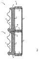
図1はモジュール型屋根葺基本構造体1を示す。基本構造体1は複数の基本構造体1で屋根2を葺くために構成される。屋根2は、屋根2の低端から棟木のような棟素子まで延びる、複数の互いに平行な傾斜垂木4を有する。断面は垂木の方向に対して横に、すなわち屋根2の水平方向で、見ている。天井板6が垂木4の下側に取り付けられていて、天井板6の下側は、屋根2が一部を形成する建物の内部空間に面している。天井板6の上方で基本構造体1の下方の、垂木4の間に、屋根2の断熱特性を高めるため、例えばEPS(発泡スチロール)の、断熱素子9が備えられている。そのような断熱素子9の使用は本発明の範囲内の選択肢である。
FIG. 1 shows a modular roof ridge basic structure 1. The basic structure 1 is configured to spread the
モジュール型屋根葺基本構造体1は内部空間12及び、使用において屋根2に面する、長方形の平底壁14を有する箱形容器10を有する。容器10は上面が開放されている。基本構造体1は開放上面を覆うためのカバー16を有する。カバー16は、図には詳細に示されていない、スナップ結合を用いて着脱可能な態様で容器10に結合される。あるいは、カバー16はプラスチック溶接のような永久態様で容器10に結合され得る。容器10は長方形の底壁14の4辺に側壁を有し、それぞれの辺において側壁は底壁14からカバー16に向けて上方に延びる。図1には側壁の内の18及び19が示されている。側壁18、19のそれぞれの上部自由端の高さ及び形状は、側壁18、19のそれぞれがカバー16に結合され、よって内部空間12が底壁14、側壁18及びカバー16で完全に囲まれるように構成される。カバー16は、2つの方向において、屋根瓦のパターンに似るような形につくられる。容器10の底壁14及び側壁18は、射出成形を用い、ガラスファイバ強化ポリプロピレンの一体部品として形成される。容器10の材料は難燃性及び耐熱性である。一実施形態において容器10は発泡コアを有する。あるいは、容器は押出成形でつくることができ、底壁14と側壁18及び19を有する容器の押出部分上に固定される別コンポーネントとして、側壁18及び19に対して垂直な側壁を設けることができる。
The modular roof ridge basic structure 1 has an
基本構造体1は、複数の基本構造体1で屋根を葺くため、基本構造体1を別の基本構造体1に結合するための結合手段を有する。結合手段はリブ20、22、26及び溝24を含む。図1の図で左側の、第1の側では、左側壁18にリブ20が設けられ、リブ20は側方に向けられる。図1の右側では側壁19に溝24が、屋根に複数の基本構造体1が取り付けられている状態において、図2に示されるように、リブ20が別の基本構造体1の溝24に嵌合するように、設けられる。右側壁19と底壁14の間のエッジに、下方に延び、垂木4の上面にある溝28に嵌合するように構成された、リブ26が設けられる。左側壁18と底壁14の間のエッジに、リブ20に平行に側方に延びる、リブ22が設けられる。垂木4にはその側面に溝30が設けられる。リブ22は溝30に嵌合するように構成される。2つの基本構造体1が取り付けられた状態で示されている図2から分かるように、基本構造体1の屋根2上への配置に際して、左側の第1の基本構造体1を、そのリブ22を垂木4'の溝30に嵌合させ、そのリブ26を垂木4''の溝28に嵌合させて、配置することができる。次に、右側の第2の基本構造体1を、リブ20及び22がそれぞれ左側の基本構造体1の溝24及び垂木4''の溝30に嵌合するように垂木4''上に初めに配置することで、配置することができる。次に、リブ26が垂木4'''の溝28に嵌合するように、基本構造体1が垂木4'''上に降ろされる。別の基本構造体1を図2に示されるように上述した右側基本構造体1の右側に配置することで、この方法を反復することができる。そうすることで、複数の基本構造体の屋根上への配置に際して、隣接基本構造体1と垂木の間にフォームクローズドインターロックカプリングが与えられる。屋根2の垂直方向または傾斜方向での、2つの隣接する基本構造体1の間の結合は、側壁18及び19に垂直に側壁の先に広がるカバー16の部分とともに第1の基本構造体1を、2つの隣接する基本構造体1のそれぞれのカバー16の間の重なりを実現するように、複数の基本構造体1の内の別の基本構造体1の、同じくその別の基本構造体1の側壁の先に広がる、カバー16の一部の上または下に、滑らせることによって与えることができる。リブ20と溝24及びリブ26と溝28の組合せは、雨水を屋根樋に流すためのドレインも形成する。すなわち、これらの組合せは、雨水のような液体が基本構造体1の下側に流れ込み得ることを、少なくともかなりの程度まで、防止する封止素子を形成する。
The basic structure 1 has a coupling means for coupling the basic structure 1 to another basic structure 1 in order to run a roof with a plurality of basic structures 1. The coupling means includes
基本構造体1の底壁14と断熱素子9の間の通路は、複数のそのような構造体が取り付けられた状態において、垂木4に平行に延びる、いくつかの構造体の下側にあってそれらに沿うダクトを形成する。この結果、基本構造体1の内部空間12内のPV素子を、例えば強制空冷を用いるか、あるいは、棟に向かってダクトを上方に流過する熱せられた空気により存在するであろう空気流で、冷却することができる。
The passage between the
(詳細は示されていない)キャリア上に取り付けられた太陽電池のパターンによって形成された(PV素子とも称される)太陽光発電素子は、基本構造体1の内部空間12内に配置される。PV素子は底壁14から少し離れて描かれているが、実際は、PV素子は接着剤によって容器10の底壁14上に固定されている。PV素子及びその電気的構成は以下で図7、8及び9を参照してさらに説明される。上で説明したように基本構造体1の内部空間12は囲われているから、PV素子は水分及び塵埃のような外部の影響を受けないでいることができる。
A photovoltaic element (also referred to as a PV element) formed by a pattern of solar cells mounted on a carrier (not shown in detail) is arranged in the
カバー16はポリカーボネートでつくられ、約80%のような、使用において電力が入射太陽光によりPV素子で発生され得るような程度に光透過性である。
The
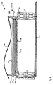
図3は、本発明にしたがう屋根葺基本構造体の第2の実施形態としてのモジュール型屋根葺基本構造体100を示す。図1と比較して同等のコンポーネントは同じ参照数字で参照される。上述したような基本構造体1のコンポーネントと、少なくとも機能において、同じであるコンポーネントは100が加えられ、別の実施形態ではそれぞれ毎に100ずつ加えられていく、参照数字で参照される。図示されるように、底壁114並びに側壁118及び119はそれぞれ、基本構造体1の壁14、18及び19に比較して薄くつくられている。基本構造体100の断熱特性を高めるため、例えばPUR(ポリウレタン)でつくられた断熱素子109が底壁114の上面に配置される。断熱素子109の上面にPV素子40が固定される。カバー116は上述したカバー16と異なるかまたは同じ形状を有することができる。これは複数の基本構造体1または100で形成される屋根葺の所要の外観に依存する。
FIG. 3 shows a modular roof roof
図4は、本発明にしたがう屋根葺基本構造体の一実施形態としてのモジュール型屋根葺基本構造体200を示す。基本構造体200は、PV素子240が基本構造体200の内部空間212内に設けられる態様を除いて、上述したような基本構造体1と基本的に同じである。PV素子240は可撓性シート上に固定された複数の太陽電池を有し、シートは、容器210の内部空間212内に、ポスト241によって吊られている。
FIG. 4 shows a modular roof ridge
図5にしたがうモジュール型屋根葺基本構造体300は基本構造体200と同等である。しかし、基本構造体300の容器310は,側壁318と319の間に延びる追加の内壁317によって設けられる、空気のための貫通路313を有する。これは、図示される側壁318、319に垂直な側面において、図示されるように、通路313が閉じられていないことを意味する。しかし、内部空間312は4つの側壁及びカバーによって完全に囲まれている。複数のそのような基本構造素子300が取り付けられた状態において、いくつかの基本構造体300を通って、垂木4に平行に延びる、ダクトを形成する通路313を設けることにより、基本構造体300の内部空間312内のPV素子を、例えば強制空冷を用いるか、あるいは、棟に向かってダクトを上方に流過する熱せられた空気により存在するであろう空気流で、冷却することができる。
The modular roof ridge
複数の基本構造体300で形成された屋根2によって覆われた建物の内側への、基本構造体300によるいかなる雑音放射も減じるため、本発明の範囲内で必要に応じる、ヘルムホルツ共振器360が底壁314の下側に備えられる。上述した基本構造体1〜200へのヘルムホルツ共振器の適用も考えられる。
In order to reduce any noise radiation by the
図6は、本発明にしたがうモジュール型屋根葺基本構造体の第5の実施形態としての屋根葺基本構造体400を示す。図6の実施形態は主に、本発明にしたがう屋根葺基本構造体、特にそのカバーの、全体構成をさらに説明するに役立つ。基本構造体400のカバー416は、2方向での、屋根瓦のパターン、さらに詳しくは3×3の瓦パターンに似るような形につくられた一体コンポーネントである。
FIG. 6 shows a roof roof
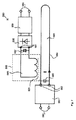
図7は発生された電力を転送するための誘導結合のアイデアを含む太陽光発電素子アセンブリのための電気回路の580の略図を示す。
FIG. 7 shows a schematic diagram of an
この例において、太陽光発電素子(図示せず)は入力端子581を介して超小型コンバータ582に接続されている。太陽光発電素子は一般に複数の太陽電池を有し、太陽電池のそれぞれは約0.5VのDC電圧を発生するように構成されている。発生されるDC電圧は、通常、入射太陽光量に基づいて大きく変動することはないが、アセンブリの実温度に基づいて若干変動し得る。しかし、発生されるDC電流は太陽電池への入射太陽光量に直接に依存し、DC電流は入射太陽光量に実質的に比例すると考えられる。
In this example, a photovoltaic power generation element (not shown) is connected to the
太陽電池は直列または並列に、あるいは直列と並列の組合せで、配列することができる。この結果、太陽光発電素子の発生電圧は広く異なり得る。DC電圧は、例えば、太陽光発電素子アセンブリ当たりで20Vから800Vもの高さまで変わり得る。いずれの場合にも、超小型コンバータ582は入力端子581における、広く変化する誘起DC電流をともなう、いかなるDC電圧も出力端子592におけるAC電圧に変換するように構成される。
Solar cells can be arranged in series or in parallel, or a combination of series and parallel. As a result, the generated voltage of the photovoltaic power generation element can vary widely. The DC voltage can vary, for example, from 20V to as high as 800V per photovoltaic element assembly. In any case, the
超小型コンバータ582は、方形波形、三角波形、正弦波形または鋸歯波形のような、ただしこれらには限定されない、いかなるタイプのAC波形も発生するように構成することができる。
The
AC電圧は次いで電流トラック584の形態の供給コイルに注入される。そのような電流トラック584は、例えば、箱形容器の底に集成される。誘導結合の効率を高めるため、電流トラックで取り囲まれる面積593を、箱形容器の底側の周方向に、またその端に、電流トラックを配置することによって大きくすることができる。AC波形の品質を高めるため、DC結合素子583を用いることができる。
The AC voltage is then injected into a supply coil in the form of a
本例において、誘導結合は電流トラック584を流過する電流が磁場及び磁束を誘起し、この磁場及び磁束がピックアップコイル585によって感受されるときに実現される。ピックアップコイル585で感受された磁場及び磁束は、出力端子594にかけてAC電圧を発生する。ピックアップコイル585は電流トラックの形態で構成することができ、あるいは単パッケージ586に構成することができる。
In this example, inductive coupling is realized when the current flowing through the
ピックアップコイル585と供給コイル584の間の誘導結合の効率はコア591を用いることで高めることができる。磁場及び磁束はコア内を空気中の何倍も良く伝搬する。コア591は、鉄またはフェライトのような、強磁性材料で、これらの材料はそれらの磁気伝導特性で知られているから、つくることができる。
The efficiency of inductive coupling between the
次に、出力端子594におけるAC電圧は、輸送端子590を介する、蓄電のための電池または電池パックへの輸送手段588、589によって変換される。輸送手段588、589はDCコンバータ588及び、励起されたエネルギーの電池への輸送を効率的に制御するための、コントローラ589を含むことができる。
Next, the AC voltage at the
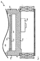
図8は、本発明にしたがう、一実施形態の太陽光発電素子アセンブリ550の断面図を示す。使用において、入射太陽光551が太陽光に透明なカバー16を通過すると、太陽光発電素子540によって電力が発生される。
FIG. 8 shows a cross-sectional view of one embodiment of a
太陽光発電素子アセンブリ550は、箱形容器510、複数の太陽電池を有する太陽光発電素子540、電流トラックの形態の供給コイル584、超小型コンバータ582及びピックアップコイル585を有する。太陽光発電素子540、超小型コンバータ582及び供給コイル584は箱形容器510の内部空間内に配されるが、ピックアップコイル585は内部空間の外側に配される。ピックアップコイルは箱形容器510の底壁514の外側領域583に取り付けることができ、あるいは屋根に存在する垂木に取り付けることができる。
The
太陽光発電素子540で発生されたDC電圧は、超小型コンバータ582によってAC電圧に変換されて、電流トラック584に注入される。電流トラックを流過する電流は箱形容器510の底壁514を透過する磁場及び磁束を誘起するであろう。磁場及び/または磁束はピックアップコイル585によって感受され、この結果、ピックアップコイル585によってAC電圧が発生される。
The DC voltage generated by the photovoltaic
電流トラック584とピックアップコイル585の間の誘導結合効率を高めるため、箱形容器510の底壁514は可能な限り薄くつくられるべきである。あるいは、底壁の材料が、鉄のような、いずれかの強磁性材料を、そのような材料は優れた磁気特性及び保磁力特性を有するから、含むべきである。
In order to increase the inductive coupling efficiency between the
図9は、本発明にしたがう、別の実施形態の太陽光発電素子アセンブリ650の断面図を示す。
FIG. 9 shows a cross-sectional view of another embodiment of a
図8の実施形態と図9の実施形態の間の違いは、図9の供給コイル584が箱形容器610の底壁614の上側553に集成されていることである。供給コイル584は、例えばワイアコイルの形態で、鋳込むかまたは集成することができる。供給コイル584を底壁614の上側553に集成することの利点は、ピックアップコイル585と供給コイル584との間隔が狭められ、この結果、これらの間の誘導結合に対する効率が良くなることである。
The difference between the embodiment of FIG. 8 and the embodiment of FIG. 9 is that the
本発明は上に開示されたような実施形態に限定されず、当業者により、発明の技能を適用する必要なしに、添付される特許請求の範囲に開示されるような本発明の範囲をこえて改変及び充実され得る。
他の実施形態
1.モジュール型屋根葺で少なくとも一部が葺かれる屋根であって、前記モジュール型屋根葺が前記屋根を葺くための複数のモジュール型基本構造体を有する、屋根において、前記モジュール型基本構造体のそれぞれが、
−内部空間及び使用において前記屋根に面する少なくとも実質的に平坦な底壁を有し、上面が開放されており、少なくとも実質的にポリマーでつくられている、箱形容器、
−前記容器の前記内部空間内に配されている太陽光発電素子、
−前記開放上面を少なくとも実質的に覆うための、前記容器に結合されている、カバーであって、使用において入射太陽光により太陽電池で電力が発生され得るような程度に光透過性であるカバー、及び
−前記複数の基本構造体で屋根を葺くために、前記基本構造体を前記屋根に、及び/または別の基本構造体に、結合するための結合手段、
を備え、
前記複数の基本構造体は前記屋根の少なくとも一部が前記複数の基本構造体によって完全に葺かれるように配置され、前記基本構造体のそれぞれはそれぞれの前記結合手段によって前記複数の基本構造体の内の少なくとも1つの隣接する別の基本構造体に結合され、前記屋根は棟に向かって互いに平行に延びる傾斜垂木を有し、前記複数の基本構造体は前記垂木上に直接に取り付けられ、前記基本構造体のそれぞれは2本の隣り合う前記垂木上に、前記垂木に対して横方向に、支持されることが好ましい、
ことを特徴とする屋根。
2.前記基本構造体において、前記カバーが着脱可能な態様で前記容器に結合されることを特徴とする実施形態1に記載の屋根。
3.前記基本構造体において、前記ポリマーがポリオレフィン、好ましくはポリプロピレンまたはポリエチレンであることを特徴とする実施形態1または2に記載の屋根。
4.前記基本構造体において、前記ポリマーが強化ポリマー、好ましくはガラスファイバ強化ポリマー、好ましくはガラスファイバ強化ポリプロピレンであることを特徴とする実施形態1から3のいずれかに記載の屋根。
5.前記強化ポリマーが積層プラスチックであるか、または発泡コアを有することを特徴とする実施形態4に記載の屋根。
6.前記強化ポリマーが難燃性及び耐熱性であることを特徴とする実施形態4または5に記載の屋根。
7.前記基本構造体において、前記カバーが、PMMA(ポリ(メチルメタクリレート))、ポリカーボネート、PET(ポリエチレンテレフタレート)、ポリプロピレン及びポリエチレンからなる群から選ばれるプラスチックを含み、好ましくは前記プラスチックが耐UV性であることを特徴とする実施形態1から6のいずれかに記載の屋根。
8.前記基本構造体の前記結合手段が前記基本構造体の別の基本構造体へのフォームクローズドカプリングのために構成されることを特徴とする実施形態1から7のいずれかに記載の屋根。
9.前記基本構造体において、前記太陽光発電素子が、前記容器の前記底壁の上面に、前記内部空間に面して、配置された複数の太陽電池を有することを特徴とする実施形態1から8のいずれかに記載の屋根。
10.前記基本構造体において、前記太陽光発電素子が可撓性シート上に固定された複数の太陽電池を有し、前記シートが前記容器の前記内部空間内に吊られていることを特徴とする実施形態1から9のいずれかに記載の屋根。
11.前記容器の前記内部空間が前記容器の壁及び前記カバーによって完全に囲まれていることを特徴とする実施形態1から10のいずれかに記載の屋根。
12.前記基本構造体において、前記カバーが、前記カバーと前記容器の間に空隙が存在するように、前記容器の前記開放上面を覆うことを特徴とする実施形態1から11のいずれかに記載の屋根。
13.前記基本構造体において、使用において空気が前記内部空間を流過できるように、前記容器が前記底壁から前記カバーまで延びる2つの対向する側壁に開口を有することを特徴とする実施形態1から12のいずれかに記載の屋根。
14.前記基本構造体において、前記カバーが、前記カバーの外側の上面に、屋根瓦のパターンの形状を有することを特徴とする実施形態1から13のいずれかに記載の屋根。
15.少なくとも1つの前記モジュール型基本構造体が、
−第1の側及び第2の側を有する支持キャリア、対応する前記太陽光発電素子が、前記支持キャリアの前記第1の側の上に配され、前記入射太陽光から直流電圧による電力を発生するために構成される、支持キャリア、
−前記太陽光発電素子に接続され、前記直流電圧を交流電圧に変換するために構成された、超小型コンバータ、及び
−誘導結合手段であって、
−前記超小型コンバータに接続された供給コイルと、
−前記支持キャリアの前記第2の側に、またはその近くに、配され、前記電力を転送するために前記供給コイルに誘導結合された、ピックアップコイルと、
を有する誘導結合手段、
を備えることを特徴とする実施形態1から14のいずれかに記載の屋根。
16.前記支持キャリア、前記太陽光発電素子、前記超小型コンバータ及び前記供給コイルが前記箱形容器の前記内部空間内に配され、前記支持キャリアの前記第2の側が前記箱形容器の底側に面していることを特徴とする実施形態15に記載の屋根。
17.前記誘導結合手段がコアをさらに有し、前記コアが前記箱形容器の前記底側を突き通り、前記供給コイルが前記箱形容器の前記内部空間内で前記コアに巻き付けられ、前記ピックアップコイルが前記箱形容器の前記内部空間の外側で前記コアに巻き付けられることを特徴とする実施形態16に記載の屋根。
18.前記支持キャリア、前記太陽光発電素子及び前記超小型コンバータが前記箱形容器の前記内部空間内に交換可能な態様で配されることを特徴とする実施形態16または17に記載の屋根。
19.前記供給コイルが前記箱形容器の前記底側に集成されることを特徴とする実施形態15または16に記載の屋根。
20.前記供給コイルが前記底側の実質的に周方向に集成されることを特徴とする実施形態19に記載の屋根。
21.前記供給コイルが前記底側に鋳込まれることを特徴とする実施形態16に記載の屋根。
22.前記供給コイルがワイアコイルであることを特徴とする実施形態15から21のいずれかに記載の屋根。
23.前記供給コイルが前記箱形容器の前記底側上に取り付けられることを特徴とする実施形態16に記載の屋根。
24.前記少なくとも1つの前記モジュール型基本構造体が、前記ピックアップコイルに接続され、前記誘導結合された電力を転送するために構成された、輸送手段をさらに備えることを特徴とする実施形態15から23のいずれかに記載の屋根。
25.前記輸送手段が前記ピックアップコイルに誘導結合された交流電圧を直流電圧に変換するためのコンバータを含むことを特徴とする実施形態24に記載の屋根。
26.前記ピックアップコイルが前記箱形コンテナの底側に取り付けられることを特徴とする実施形態16または17に記載の屋根。
27.前記太陽光発電素子が複数の太陽電池を有することを特徴とする実施形態15から26のいずれかに記載の屋根。
28.前記支持キャリアが可撓性シートを含むことを特徴とする実施形態25から27のいずれかに記載の屋根。
The present invention is not limited to the embodiments as disclosed above and goes beyond the scope of the present invention as disclosed in the appended claims without the need for a person skilled in the art to apply the skills of the invention. Can be modified and enhanced.
Other embodiments
1. Each of the modular basic structures is a roof that is at least partially laid with a modular roof ridge, wherein the modular roof ridge has a plurality of modular basic structures for rolling the roof. But,
A box-shaped container having an interior space and at least a substantially flat bottom wall facing the roof in use, open at the top and made at least substantially of a polymer;
-A photovoltaic element arranged in the internal space of the container;
A cover coupled to the container for covering at least substantially the open upper surface, the cover being light transmissive to the extent that in use solar power can be generated by incident solar light ,as well as
A coupling means for coupling the basic structure to the roof and / or to another basic structure for roofing with the plurality of basic structures;
With
The plurality of basic structures are arranged such that at least a part of the roof is completely covered by the plurality of basic structures, and each of the basic structures is formed by the coupling means. Coupled to at least one other adjacent basic structure in the roof, the roof having inclined rafters extending parallel to each other toward the ridge, the plurality of basic structures being mounted directly on the rafter, Each of the basic structures is preferably supported on two adjacent rafters, laterally with respect to the rafters,
A roof characterized by that.
2. The roof according to embodiment 1, wherein in the basic structure, the cover is coupled to the container in a detachable manner.
3. The roof according to
4). The roof according to any of embodiments 1 to 3, characterized in that, in the basic structure, the polymer is a reinforced polymer, preferably a glass fiber reinforced polymer, preferably a glass fiber reinforced polypropylene.
5). The roof of embodiment 4, wherein the reinforced polymer is a laminated plastic or has a foam core.
6). The roof according to embodiment 4 or 5, wherein the reinforced polymer is flame retardant and heat resistant.
7). In the basic structure, the cover includes a plastic selected from the group consisting of PMMA (poly (methyl methacrylate)), polycarbonate, PET (polyethylene terephthalate), polypropylene, and polyethylene, and preferably the plastic is UV resistant. The roof according to any one of Embodiments 1 to 6, wherein:
8). The roof according to any of embodiments 1 to 7, characterized in that the coupling means of the basic structure is configured for foam-closed coupling of the basic structure to another basic structure.
9. In the basic structure, the solar power generation element includes a plurality of solar cells arranged on the upper surface of the bottom wall of the container so as to face the internal space. The roof according to any of the above.
10. In the basic structure, the photovoltaic power generation element includes a plurality of solar cells fixed on a flexible sheet, and the sheet is suspended in the internal space of the container. The roof according to any one of Forms 1 to 9.
11. The roof according to any one of embodiments 1 to 10, wherein the internal space of the container is completely surrounded by a wall of the container and the cover.
12 12. The roof according to any one of embodiments 1 to 11, wherein in the basic structure, the cover covers the open upper surface of the container such that a gap exists between the cover and the container. .
13. Embodiments 1 to 12 characterized in that in the basic structure, the container has openings on two opposing side walls extending from the bottom wall to the cover so that air can flow through the interior space in use. The roof according to any of the above.
14 The roof according to any one of Embodiments 1 to 13, wherein the cover has a roof tile pattern shape on the outer upper surface of the cover in the basic structure.
15. At least one of the modular basic structures is
A support carrier having a first side and a second side, the corresponding photovoltaic power generation element is arranged on the first side of the support carrier, and generates power from the incident sunlight by a DC voltage A support carrier, configured to
-A micro converter connected to the photovoltaic element and configured to convert the DC voltage into an AC voltage; and
-Inductive coupling means,
A supply coil connected to the micro converter;
A pickup coil disposed on or near the second side of the support carrier and inductively coupled to the supply coil to transfer the power;
Having inductive coupling means,
The roof according to any one of embodiments 1 to 14, comprising:
16. The support carrier, the photovoltaic power generation element, the micro converter, and the supply coil are disposed in the internal space of the box-shaped container, and the second side of the support carrier faces the bottom side of the box-shaped container. The roof according to embodiment 15, characterized in that:
17. The inductive coupling means further includes a core, the core penetrates the bottom side of the box-shaped container, the supply coil is wound around the core in the inner space of the box-shaped container, and the pickup coil is The roof according to
18. The roof according to
19. The roof according to
20. The roof of
21. The roof according to
22. The roof according to any of embodiments 15 to 21, wherein the supply coil is a wire coil.
23. The roof of
24. Embodiments 15 to 23, wherein the at least one modular basic structure further comprises a transport means connected to the pickup coil and configured to transfer the inductively coupled power. The roof according to any one.
25. 25. The roof of
26. The roof according to
27. 27. The roof according to any one of embodiments 15 to 26, wherein the solar power generation element has a plurality of solar cells.
28. 28. A roof according to any of embodiments 25 to 27, wherein the support carrier comprises a flexible sheet.
1,100,200,300,400 モジュール型屋根葺基本構造体
2 屋根
4,4',4'',4''' 垂木
6 天井板
9,109 断熱素子
10,110,310,510,610 箱形容器
12,212,312 内部空間
14,114,514,614 底壁
16,116,416 カバー
18,19,118,119.318,319 側壁
20,22,26 リブ
24,28.30 溝
40,240,540 PV素子(太陽光発電素子)
241 ポスト
313 貫通路
317 内壁
360 ヘルムホルツ共振器
550 太陽光発電素子アセンブリ
551 太陽光
553 底壁上側
580 電気回路
581 超小型コンバータの入力端子
582 超小型コンバータ
583 DC結合素子
584 電流トラック(供給コイル)
585 ピックアップコイル
586 単パッケージ
588 DCコンバータ
589 コントローラ
591 コア
592 超小型コンバータの出力端子
594 ピックアップコイルの出力端子
1,100,200,300,400 Module type roof roof
585
Claims (19)
−内部空間及び使用において前記屋根に面する少なくとも実質的に平坦な底壁を有し、上面が開放されており、少なくとも実質的にポリマーでつくられている、箱形容器、
−前記容器の前記内部空間内に配されている太陽光発電素子、
−前記開放上面を少なくとも実質的に覆うための、前記容器に結合されている、カバーであって、使用において入射太陽光により太陽電池で電力が発生され得るような程度に光透過性であるカバー、及び
−前記複数の基本構造体で屋根を葺くために、前記基本構造体を前記屋根に、及び/または別の基本構造体に、結合するための結合手段、
を備え、
前記複数の基本構造体は前記屋根の少なくとも一部が前記複数の基本構造体によって完全に葺かれるように配置され、前記基本構造体のそれぞれはそれぞれの前記結合手段によって前記複数の基本構造体の内の少なくとも1つの隣接する別の基本構造体に結合され、前記屋根は棟に向かって互いに平行に延びる傾斜垂木を有し、前記複数の基本構造体は前記垂木上に直接に取り付けられている、
ことを特徴とする屋根。 Each of the modular basic structures is a roof that is at least partially laid with a modular roof ridge, wherein the modular roof ridge has a plurality of modular basic structures for rolling the roof. But,
A box-shaped container having an interior space and at least a substantially flat bottom wall facing the roof in use, open at the top and made at least substantially of a polymer;
-A photovoltaic element arranged in the internal space of the container;
A cover coupled to the container for covering at least substantially the open upper surface, the cover being light transmissive to the extent that in use solar power can be generated by incident solar light Coupling means for coupling the basic structure to the roof and / or to another basic structure for roofing with the plurality of basic structures;
With
The plurality of basic structures are arranged such that at least a part of the roof is completely covered by the plurality of basic structures, and each of the basic structures is formed by the coupling means. Coupled to at least one other adjacent basic structure in the roof, the roof has sloping rafters extending parallel to each other toward the ridge, and the plurality of basic structures are mounted directly on the rafters ,
A roof characterized by that.
−第1の側及び第2の側を有する支持キャリア、対応する前記太陽光発電素子が、前記支持キャリアの前記第1の側の上に配され、前記入射太陽光から直流電圧による電力を発生するために構成される、支持キャリア、
−前記太陽光発電素子に接続され、前記直流電圧を交流電圧に変換するために構成された、超小型コンバータ、及び
−誘導結合手段であって、
−前記超小型コンバータに接続された供給コイルと、
−前記支持キャリアの前記第2の側に、またはその近くに、配され、前記電力を転送するために前記供給コイルに誘導結合された、ピックアップコイルと、
を有する誘導結合手段、
を備えることを特徴とする請求項1から12のいずれか1項に記載の屋根。 At least one of the modular basic structures is
A support carrier having a first side and a second side, the corresponding photovoltaic power generation element is arranged on the first side of the support carrier, and generates power from the incident sunlight by a DC voltage A support carrier, configured to
A micro converter connected to the photovoltaic element and configured to convert the DC voltage into an AC voltage, and-an inductive coupling means,
A supply coil connected to the micro converter;
A pickup coil disposed on or near the second side of the support carrier and inductively coupled to the supply coil to transfer the power;
Having inductive coupling means,
The roof according to claim 1, wherein the roof is provided.
前記支持キャリア、前記太陽光発電素子及び前記超小型コンバータが前記箱形容器の前記内部空間内に交換可能な態様で配され、かつ
前記支持キャリアの前記第2の側が前記箱形容器の底側に面していることを特徴とする請求項13に記載の屋根。 The support carrier, the photovoltaic power generation element, the microminiature converter and the supply coil are arranged in the internal space of the box-shaped container,
The support carrier, the photovoltaic power generation element, and the micro converter are arranged in an exchangeable manner in the internal space of the box-shaped container, and the second side of the support carrier is the bottom side of the box-shaped container The roof according to claim 13, which faces the roof.
前記供給コイルが、前記箱形容器の前記底側に集成される、もしくは前記箱形容器の前記底側に鋳込まれる、もしくは前記箱形容器の前記底側上に取り付けられる、
ことを特徴とする請求項13に記載の屋根。 The supply coil is a wire coil and / or the supply coil is assembled on the bottom side of the box-shaped container, or is cast on the bottom side of the box-shaped container, or the box-shaped container Mounted on the bottom side,
The roof according to claim 13.
The roof according to claim 14, wherein the pickup coil is attached to a bottom side of the box-shaped container.
Applications Claiming Priority (5)
| Application Number | Priority Date | Filing Date | Title |
|---|---|---|---|
| EP14158245 | 2014-03-07 | ||
| EP14158245.2 | 2014-03-07 | ||
| EP14158244 | 2014-03-07 | ||
| EP14158244.5 | 2014-03-07 | ||
| PCT/EP2015/054603 WO2015132336A1 (en) | 2014-03-07 | 2015-03-05 | Modular roof covering element, modular roof covering, and roof |
Publications (3)
| Publication Number | Publication Date |
|---|---|
| JP2017510735A JP2017510735A (en) | 2017-04-13 |
| JP2017510735A5 JP2017510735A5 (en) | 2018-03-08 |
| JP6572228B2 true JP6572228B2 (en) | 2019-09-04 |
Family
ID=52630368
Family Applications (1)
| Application Number | Title | Priority Date | Filing Date |
|---|---|---|---|
| JP2016554881A Active JP6572228B2 (en) | 2014-03-07 | 2015-03-05 | Modular roof roof basic structure, modular roof roof and roof |
Country Status (7)
| Country | Link |
|---|---|
| US (1) | US10027274B2 (en) |
| EP (1) | EP3114414B1 (en) |
| JP (1) | JP6572228B2 (en) |
| CN (1) | CN106105021B (en) |
| BR (1) | BR112016017413B1 (en) |
| ES (1) | ES2745557T3 (en) |
| WO (1) | WO2015132336A1 (en) |
Families Citing this family (12)
| Publication number | Priority date | Publication date | Assignee | Title |
|---|---|---|---|---|
| EP3168982A1 (en) * | 2015-11-13 | 2017-05-17 | S.A. Imperbel N.V. | Flexible multilayer system |
| CN110234821B (en) * | 2017-01-02 | 2021-06-25 | Sabic环球技术有限责任公司 | Roof forming element, roof and method of manufacture |
| EP3563423B1 (en) * | 2017-01-02 | 2020-08-26 | SABIC Global Technologies B.V. | A photovoltaic packaging, and a method for manufacturing such a photovoltaic packaging |
| WO2018122200A1 (en) | 2017-01-02 | 2018-07-05 | Sabic Global Technologies B.V. | Solar roof forming element, roof, and method of manufacturing |
| CN107171618A (en) * | 2017-05-24 | 2017-09-15 | 佛山市森和业丰纸制品有限公司 | A kind of heat insulation and dissipation photovoltaic tile |
| CN107447935B (en) * | 2017-08-02 | 2023-03-21 | 天津大学 | Modularization intelligence heat preservation roof that insulates against heat |
| WO2020007967A1 (en) * | 2018-07-04 | 2020-01-09 | Sabic Global Technologies B.V. | Solar roof forming element, building, and method of forming a roof |
| MX2022006152A (en) | 2019-11-26 | 2022-08-08 | Bmic Llc | Roofing panels with water shedding features. |
| WO2021202327A1 (en) | 2020-03-30 | 2021-10-07 | Building Materials Investment Corporation | Interlocking laminated structural roofing panels |
| US11855580B2 (en) | 2020-11-09 | 2023-12-26 | Bmic Llc | Interlocking structural roofing panels with integrated solar panels |
| MX2022006329A (en) | 2021-05-25 | 2022-11-28 | Bmic Llc | Panelized roofing system. |
| IT202200009476A1 (en) * | 2022-05-09 | 2023-11-09 | Sic Divisione Elettr S R L U | Hybrid solar panel and photovoltaic and thermal roof |
Family Cites Families (33)
| Publication number | Priority date | Publication date | Assignee | Title |
|---|---|---|---|---|
| JPS6055650A (en) | 1983-09-06 | 1985-03-30 | Matsushita Electric Ind Co Ltd | Solar battery module |
| IE64906B1 (en) * | 1989-02-24 | 1995-09-20 | Bq Technology Limited | Solar panel |
| JP3528409B2 (en) | 1996-04-08 | 2004-05-17 | 鐘淵化学工業株式会社 | Roof panel with photovoltaic function |
| JPH11150287A (en) * | 1997-09-10 | 1999-06-02 | Canon Inc | Solar cell module, solar cell with enclosure, method for fitting enclosure with the solar cell, and solar power generating system |
| US6320116B1 (en) | 1997-09-26 | 2001-11-20 | Evergreen Solar, Inc. | Methods for improving polymeric materials for use in solar cell applications |
| WO2000030184A1 (en) * | 1998-11-13 | 2000-05-25 | Us Solar Roof | Photovoltaic roof tile |
| JP2000269535A (en) * | 1999-01-14 | 2000-09-29 | Canon Inc | Solar battery module and power generating device and method for separating the solar battery module and method for reproducing the module |
| WO2000075455A1 (en) * | 1999-06-09 | 2000-12-14 | Kaneka Corporation | Roof tile for solar cell module |
| WO2004095589A2 (en) * | 2003-04-16 | 2004-11-04 | Bp Corporation North America Inc. | Pan for shipping and installing solar panel on a roof |
| ITFR20060023A1 (en) * | 2006-08-16 | 2008-02-17 | Nardis Maurizio De | COVERING SYSTEM OF ROOFS AND PARASTI OF BUILDINGS WITH THERMO INSULATING MUTLIFUNCTION TILES, VENTILATED WITHOUT ENVIRONMENTAL IMPACT WITH SOLAR AND PHOTOVOLTAIC ABSORPTION FOR THE PRODUCTION OF HOT WATER AND ELECTRIC ENERGY, USING THE ENTIRE SURFACE CO |
| US8065841B2 (en) | 2006-12-29 | 2011-11-29 | Antonic James P | Roof panel systems for building construction |
| FR2915345B1 (en) * | 2007-04-20 | 2009-07-03 | Imphy Alloys Sa | BATI SUPPORT OF AN ELECTRICALLY ACTIVE PANEL SUCH AS A PHOTOVOLTAIC PANEL |
| WO2008137966A2 (en) * | 2007-05-07 | 2008-11-13 | Robert Stancel | Structures for low cost, reliable solar roofing |
| EP2171769A2 (en) | 2007-06-28 | 2010-04-07 | Husnu M. Kalkanoglu | Photovoltaic roofing tiles and methods for making them |
| US8813460B2 (en) * | 2007-09-21 | 2014-08-26 | Andalay Solar, Inc. | Mounting system for solar panels |
| US8438796B2 (en) | 2007-11-06 | 2013-05-14 | Certainteed Corporation | Photovoltaic roofing elements including tie layer systems, and roofs using them, and methods for making them |
| CA2723395C (en) | 2008-05-05 | 2014-11-25 | Dow Global Technologies Inc. | Photovoltaic device assembly and method |
| ITPR20080035A1 (en) * | 2008-05-23 | 2009-11-24 | Atma Tec S R L | MODULAR UNIT MODULAR TO CREATE BEARING STRUCTURES, FOR CONSTRUCTION AND / OR SUPPORT FOR PHOTOVOLTAIC CARPET. |
| FR2931932B1 (en) * | 2008-05-27 | 2010-08-27 | Jean Claude Jeandeaud | SUPPORT DEVICE FOR SOLAR ENERGY RECOVERY MODULES, SOLAR ENERGY RECOVERY UNIT, AND METHOD FOR MOUNTING SOLAR ENERGY RECOVERY MODULES. |
| US8476523B2 (en) * | 2008-08-25 | 2013-07-02 | Enpulz, L.L.C. | Solar panel ready tiles |
| FR2939162A1 (en) | 2008-12-01 | 2010-06-04 | Saint Gobain | SOLAR ROOF |
| FR2947099B1 (en) | 2009-06-17 | 2013-11-15 | Cynegy Holdings France | PHOTOVOLTAIC TILE FOR ROOF |
| EP2461973B9 (en) | 2009-07-23 | 2015-04-29 | RENOLIT Belgium N.V. | Photovoltaic modules with polypropylene based backsheet |
| EP2513774A4 (en) | 2009-12-18 | 2013-09-04 | Nokia Corp | Method and apparatus for projecting a user interface via partition streaming |
| TW201122193A (en) * | 2009-12-30 | 2011-07-01 | Axuntek Solar Energy | Solar panel tile structure and combination thereof |
| US8397447B2 (en) * | 2010-04-15 | 2013-03-19 | Eco Solar Generation Llc | Roof truss compatible for solar panels |
| DE102010019815A1 (en) * | 2010-05-10 | 2011-11-10 | Max Amtmann | Photovoltaic system for initial arrangement and retrofitting of roof of private residential building, has communication equipment for transmitting electric power from solar cell modules to power supply unit via electromagnetic coupling |
| EP2390924A1 (en) * | 2010-05-26 | 2011-11-30 | Thesan S.p.A. | Building roof with rows of curved tiles alternating with strip-shaped solar modules, and sheet-metal panel for making said roof |
| EP2617568A1 (en) | 2010-08-16 | 2013-07-24 | 3M Innovative Properties Company | Polyolefin-based solar backsheet |
| US9048358B2 (en) | 2010-12-17 | 2015-06-02 | Dow Global Technologies Llc | Photovoltaic device |
| US8193788B2 (en) * | 2011-04-27 | 2012-06-05 | Solarbridge Technologies, Inc. | Method and device for controlling a configurable power supply to provide AC and/or DC power output |
| SE537409C2 (en) * | 2012-03-08 | 2015-04-21 | Törnerfälts Fastighets Ab | Ceiling for absorbing solar energy |
| DE102014111926A1 (en) * | 2013-08-22 | 2015-02-26 | Plasto Composite Gmbh | roof element |
-
2015
- 2015-03-05 ES ES15708501T patent/ES2745557T3/en active Active
- 2015-03-05 EP EP15708501.0A patent/EP3114414B1/en active Active
- 2015-03-05 WO PCT/EP2015/054603 patent/WO2015132336A1/en active Application Filing
- 2015-03-05 CN CN201580012137.1A patent/CN106105021B/en active Active
- 2015-03-05 BR BR112016017413-5A patent/BR112016017413B1/en active IP Right Grant
- 2015-03-05 US US15/124,063 patent/US10027274B2/en active Active
- 2015-03-05 JP JP2016554881A patent/JP6572228B2/en active Active
Also Published As
| Publication number | Publication date |
|---|---|
| JP2017510735A (en) | 2017-04-13 |
| CN106105021A (en) | 2016-11-09 |
| EP3114414A1 (en) | 2017-01-11 |
| WO2015132336A1 (en) | 2015-09-11 |
| BR112016017413A8 (en) | 2023-01-31 |
| US10027274B2 (en) | 2018-07-17 |
| BR112016017413A2 (en) | 2017-08-08 |
| CN106105021B (en) | 2019-06-25 |
| US20170019061A1 (en) | 2017-01-19 |
| BR112016017413B1 (en) | 2023-04-11 |
| ES2745557T3 (en) | 2020-03-02 |
| EP3114414B1 (en) | 2019-06-26 |
Similar Documents
| Publication | Publication Date | Title |
|---|---|---|
| JP6572228B2 (en) | Modular roof roof basic structure, modular roof roof and roof | |
| US11018618B2 (en) | Photovoltaic systems | |
| US20120060902A1 (en) | System and method for frameless laminated solar panels | |
| MX2013011512A (en) | Roof integrated solar panel system with side mounted micro inverters. | |
| CN103918091B (en) | Photovoltaic panel for power panel | |
| CN103563246A (en) | Shingle-like photovoltaic modules | |
| WO1994016170A1 (en) | Roof installed with solar batteries | |
| EA032890B1 (en) | Panel equipped with a photovoltaic device | |
| WO2017219798A1 (en) | Roof comprising solar battery assembly | |
| AU2015411242B2 (en) | Solar thermal collector | |
| CN203654630U (en) | Photovoltaic tile for being integrated with roof building | |
| CN104124913A (en) | New solar roof integration power generation system | |
| US8946542B1 (en) | Solar module bonding method integrated into a pan structure | |
| US20120285533A1 (en) | Construction material structure for use with solar power | |
| JPH0893159A (en) | Mounting method for solar cell | |
| CN209686749U (en) | A kind of solar energy balcony shutter | |
| JP3207592U (en) | Snow melting roof structure and snow melting roof structure | |
| JP2010236270A (en) | Drainage structure having external facing structure with integrated solar energy conversion module | |
| JP6445498B2 (en) | Snow melting roof structure and snow melting roof structure | |
| CN204590451U (en) | Utilize solar electrical energy generation watt | |
| JP2019049194A (en) | Snow melting roof structure body and snow melting roof structure | |
| JP6415797B2 (en) | Exterior structure using solar cells | |
| CN209338978U (en) | Overpass | |
| JP2006274551A (en) | Photovoltaic generation system | |
| JP5527675B2 (en) | Drainage structure of solar energy conversion module integrated exterior structure |
Legal Events
| Date | Code | Title | Description |
|---|---|---|---|
| A521 | Request for written amendment filed |
Free format text: JAPANESE INTERMEDIATE CODE: A523 Effective date: 20160902 |
|
| RD02 | Notification of acceptance of power of attorney |
Free format text: JAPANESE INTERMEDIATE CODE: A7422 Effective date: 20170928 |
|
| A521 | Request for written amendment filed |
Free format text: JAPANESE INTERMEDIATE CODE: A523 Effective date: 20180125 |
|
| A621 | Written request for application examination |
Free format text: JAPANESE INTERMEDIATE CODE: A621 Effective date: 20180125 |
|
| A977 | Report on retrieval |
Free format text: JAPANESE INTERMEDIATE CODE: A971007 Effective date: 20181225 |
|
| A131 | Notification of reasons for refusal |
Free format text: JAPANESE INTERMEDIATE CODE: A131 Effective date: 20190117 |
|
| A521 | Request for written amendment filed |
Free format text: JAPANESE INTERMEDIATE CODE: A523 Effective date: 20190204 |
|
| TRDD | Decision of grant or rejection written | ||
| A01 | Written decision to grant a patent or to grant a registration (utility model) |
Free format text: JAPANESE INTERMEDIATE CODE: A01 Effective date: 20190711 |
|
| A61 | First payment of annual fees (during grant procedure) |
Free format text: JAPANESE INTERMEDIATE CODE: A61 Effective date: 20190809 |
|
| R150 | Certificate of patent or registration of utility model |
Ref document number: 6572228 Country of ref document: JP Free format text: JAPANESE INTERMEDIATE CODE: R150 |
|
| R250 | Receipt of annual fees |
Free format text: JAPANESE INTERMEDIATE CODE: R250 |
|
| R250 | Receipt of annual fees |
Free format text: JAPANESE INTERMEDIATE CODE: R250 |