JP6496496B2 - Power storage system and control method thereof - Google Patents
Power storage system and control method thereof Download PDFInfo
- Publication number
- JP6496496B2 JP6496496B2 JP2014120288A JP2014120288A JP6496496B2 JP 6496496 B2 JP6496496 B2 JP 6496496B2 JP 2014120288 A JP2014120288 A JP 2014120288A JP 2014120288 A JP2014120288 A JP 2014120288A JP 6496496 B2 JP6496496 B2 JP 6496496B2
- Authority
- JP
- Japan
- Prior art keywords
- secondary battery
- capacitor
- current
- power
- converter
- Prior art date
- Legal status (The legal status is an assumption and is not a legal conclusion. Google has not performed a legal analysis and makes no representation as to the accuracy of the status listed.)
- Active
Links
- 238000000034 method Methods 0.000 title claims description 12
- 239000003990 capacitor Substances 0.000 claims description 143
- 208000028659 discharge Diseases 0.000 description 40
- 238000007599 discharging Methods 0.000 description 29
- 230000000052 comparative effect Effects 0.000 description 23
- 230000007423 decrease Effects 0.000 description 5
- 238000006243 chemical reaction Methods 0.000 description 4
- 238000010586 diagram Methods 0.000 description 4
- 230000008859 change Effects 0.000 description 3
- 238000012795 verification Methods 0.000 description 3
- HBBGRARXTFLTSG-UHFFFAOYSA-N Lithium ion Chemical compound [Li+] HBBGRARXTFLTSG-UHFFFAOYSA-N 0.000 description 2
- PXHVJJICTQNCMI-UHFFFAOYSA-N Nickel Chemical compound [Ni] PXHVJJICTQNCMI-UHFFFAOYSA-N 0.000 description 2
- 238000013459 approach Methods 0.000 description 2
- 230000006866 deterioration Effects 0.000 description 2
- 230000020169 heat generation Effects 0.000 description 2
- 230000006872 improvement Effects 0.000 description 2
- 229910001416 lithium ion Inorganic materials 0.000 description 2
- 238000012546 transfer Methods 0.000 description 2
- UFHFLCQGNIYNRP-UHFFFAOYSA-N Hydrogen Chemical compound [H][H] UFHFLCQGNIYNRP-UHFFFAOYSA-N 0.000 description 1
- 238000012937 correction Methods 0.000 description 1
- 230000003247 decreasing effect Effects 0.000 description 1
- 238000001514 detection method Methods 0.000 description 1
- 230000000694 effects Effects 0.000 description 1
- 230000005611 electricity Effects 0.000 description 1
- 229910052739 hydrogen Inorganic materials 0.000 description 1
- 239000001257 hydrogen Substances 0.000 description 1
- 238000012986 modification Methods 0.000 description 1
- 230000004048 modification Effects 0.000 description 1
- 229910052759 nickel Inorganic materials 0.000 description 1
- 230000009467 reduction Effects 0.000 description 1
- 239000000725 suspension Substances 0.000 description 1
Images


Classifications
-
- H—ELECTRICITY
- H02—GENERATION; CONVERSION OR DISTRIBUTION OF ELECTRIC POWER
- H02J—CIRCUIT ARRANGEMENTS OR SYSTEMS FOR SUPPLYING OR DISTRIBUTING ELECTRIC POWER; SYSTEMS FOR STORING ELECTRIC ENERGY
- H02J7/00—Circuit arrangements for charging or depolarising batteries or for supplying loads from batteries
- H02J7/34—Parallel operation in networks using both storage and other dc sources, e.g. providing buffering
- H02J7/345—Parallel operation in networks using both storage and other dc sources, e.g. providing buffering using capacitors as storage or buffering devices
-
- H—ELECTRICITY
- H02—GENERATION; CONVERSION OR DISTRIBUTION OF ELECTRIC POWER
- H02J—CIRCUIT ARRANGEMENTS OR SYSTEMS FOR SUPPLYING OR DISTRIBUTING ELECTRIC POWER; SYSTEMS FOR STORING ELECTRIC ENERGY
- H02J7/00—Circuit arrangements for charging or depolarising batteries or for supplying loads from batteries
- H02J7/14—Circuit arrangements for charging or depolarising batteries or for supplying loads from batteries for charging batteries from dynamo-electric generators driven at varying speed, e.g. on vehicle
- H02J7/1423—Circuit arrangements for charging or depolarising batteries or for supplying loads from batteries for charging batteries from dynamo-electric generators driven at varying speed, e.g. on vehicle with multiple batteries
-
- H—ELECTRICITY
- H02—GENERATION; CONVERSION OR DISTRIBUTION OF ELECTRIC POWER
- H02J—CIRCUIT ARRANGEMENTS OR SYSTEMS FOR SUPPLYING OR DISTRIBUTING ELECTRIC POWER; SYSTEMS FOR STORING ELECTRIC ENERGY
- H02J2310/00—The network for supplying or distributing electric power characterised by its spatial reach or by the load
- H02J2310/40—The network being an on-board power network, i.e. within a vehicle
- H02J2310/42—The network being an on-board power network, i.e. within a vehicle for ships or vessels
Landscapes
- Engineering & Computer Science (AREA)
- Power Engineering (AREA)
- Charge And Discharge Circuits For Batteries Or The Like (AREA)
- Secondary Cells (AREA)
Description
本発明は、二次電池およびキャパシタを備えている電力貯蔵システムおよびその制御方法に関する。 The present invention relates to a power storage system including a secondary battery and a capacitor, and a control method thereof.
従来、高エネルギ密度および高出力密度を両立する電力貯蔵システムとして、二次電池およびキャパシタを組み合わせたハイブリッドシステムが知られている。ただし、二次電池の寿命の短さがハイブリッドシステムを船舶などの輸送機器に搭載する上で問題となっている。このため、長寿命化を図ったハイブリッドシステムとして、たとえば、非特許文献1のハイブリッド電源システムが知られている。 Conventionally, a hybrid system combining a secondary battery and a capacitor is known as an electric power storage system that achieves both high energy density and high output density. However, the short life of the secondary battery is a problem when the hybrid system is mounted on a transportation device such as a ship. For this reason, for example, the hybrid power supply system disclosed in Non-Patent Document 1 is known as a hybrid system that extends the life.
このハイブリッド電源システムでは、低周波成分の電力を電池が供給し、高い周波数成分の電力を電気二重層キャパシタが供給している。この高周波成分をHPF(High Pass Filter)で分離して、HPFの時定数TEDLCをキャパシタの容量および充放電周期に基づいて設定している。また、キャパシタの過充電および過放電を防止するために、比例補償器を用いて、電池がキャパシタの損失分を供給できるように比例補償器の比例ゲインkpを設定している。 In this hybrid power supply system, a battery supplies power of a low frequency component, and an electric double layer capacitor supplies power of a high frequency component. This high frequency component is separated by an HPF (High Pass Filter), and the time constant T EDLC of the HPF is set based on the capacitance of the capacitor and the charge / discharge cycle. Further, in order to prevent overcharging and overdischarging of the capacitor, the proportional gain kp of the proportional compensator is set using a proportional compensator so that the battery can supply the loss of the capacitor.
上記ハイブリッド電源システムでは、制御パラメータ(HPFの時定数TEDLC、比例補償器の比例ゲインkp)が負荷変動の特性(周波数、大きさ)に依存するため、ハイブリッド電源システムが汎用性に欠けている。 In the above hybrid power supply system, the control parameters (HPF time constant T EDLC , proportional compensator proportional gain kp) depend on the characteristics (frequency, magnitude) of the load fluctuation, and therefore the hybrid power supply system lacks versatility. .
すなわち、キャパシタの容量および充放電周期に基づいたHPFの時定数TEDLCは、負荷変動の周波数に依存して設定される。たとえば、時定数TEDLCは、キャパシタが負担する負荷変動の周波数F1に対応した時定数T1(=1/F1)より大きく、電池が負担する負荷変動の周波数F2に対応した時定数T2(=1/F2)より小さな値に設定される。この場合、充放電パターンの変化や別システムへの適用などによって負荷変動の周波数が変化すると、設定された時定数TEDLCが変化した負荷変動の周波数に適合しなくなる。T1<T2<TEDLCになると、全ての電力をキャパシタが負担することになる。一方、TEDLC<T1<T2になると、全ての電力を電池が負担することになる。よって、負荷変動の周波数に応じて時定数TEDLCを調整しなければならない。 That is, the HPF time constant T EDLC based on the capacitance of the capacitor and the charge / discharge cycle is set depending on the frequency of the load fluctuation. For example, the time constant T EDLC is larger than the time constant T1 (= 1 / F1) corresponding to the load fluctuation frequency F1 borne by the capacitor, and the time constant T2 (= 1) corresponding to the load fluctuation frequency F2 borne by the battery. / F2) is set to a smaller value. In this case, if the load fluctuation frequency changes due to a change in charge / discharge pattern or application to another system, the set time constant T EDLC does not match the changed load fluctuation frequency. When T1 <T2 <T EDLC , the capacitor bears all the power. On the other hand, when T EDLC <T1 <T2, the battery bears all the electric power. Therefore, the time constant T EDLC must be adjusted according to the load fluctuation frequency.
また、比例補償器の比例ゲインkpは負荷変動の大きさに依存する。負荷変動の大きさに対して比例ゲインkpが小さすぎると、キャパシタの損失を補償できず、キャパシタの電圧が下限に達してしまう。一方、負荷変動の大きさに対して比例ゲインkpが大きすぎると、キャパシタの電圧を一定にしようと働き、電池からの電力供給が増加してしまう。よって、負荷変動の大きさに応じて比例ゲインkpを調整しなければならない。 Further, the proportional gain kp of the proportional compensator depends on the magnitude of the load fluctuation. If the proportional gain kp is too small with respect to the magnitude of the load fluctuation, the loss of the capacitor cannot be compensated, and the voltage of the capacitor reaches the lower limit. On the other hand, if the proportional gain kp is too large with respect to the magnitude of the load fluctuation, the capacitor voltage works to be constant, and the power supply from the battery increases. Therefore, the proportional gain kp must be adjusted according to the magnitude of the load fluctuation.
本発明はこのような課題を解決するためになされたものであり、汎用性が高く、長寿命化が図られた電力貯蔵システムおよびその制御方法を提供することを目的としている。 The present invention has been made to solve such a problem, and an object of the present invention is to provide a power storage system that is highly versatile and has a long service life, and a control method therefor.
本発明のある態様に係る電力貯蔵システムは、負荷側端子が負荷に接続される電力変換器と、前記電力変換器の電源側端子に接続された二次電池と、前記電力変換器の電源側端子にDC/DCコンバータを介して前記二次電池に並列に接続されたキャパシタと、前記二次電池より前記キャパシタを優先して充放電させるように前記DC/DCコンバータを制御する制御器と、を備えている。 An electric power storage system according to an aspect of the present invention includes a power converter in which a load side terminal is connected to a load, a secondary battery connected to a power source side terminal of the power converter, and a power source side of the power converter. A capacitor connected in parallel to the secondary battery via a DC / DC converter at a terminal, and a controller for controlling the DC / DC converter so that the capacitor is charged and discharged with priority over the secondary battery; It has.
この構成によれば、二次電池およびキャパシタの充放電が負荷変動の周波数および大きさに依存しないので、電力貯蔵システムの汎用性が高い。また、二次電池よりキャパシタを優先して充放電させるので、二次電池よりキャパシタを優先しない場合に比べて二次電池の充放電回数が減少し、二次電池の寿命が長くなる。その結果、電力貯蔵システムの長寿命化を図ることができる。 According to this configuration, since the charge / discharge of the secondary battery and the capacitor does not depend on the frequency and magnitude of the load fluctuation, the versatility of the power storage system is high. In addition, since the capacitor is charged and discharged with priority over the secondary battery, the number of times the secondary battery is charged and discharged is reduced as compared with the case where the capacitor is not prioritized over the secondary battery, and the life of the secondary battery is extended. As a result, the life of the power storage system can be extended.
電力貯蔵システムでは、前記制御器は、零または零に近い所定の二次電池電流目標値に対する前記二次電池の電流の偏差に基づいて前記キャパシタ電流目標値を生成する第1制御部と、前記キャパシタ電流目標値に対する前記キャパシタの電流の偏差に基づいて前記DC/DCコンバータの通流率を生成し、これを前記DC/DCコンバータに出力する第2制御部と、を含んでいてもよい。 In the power storage system, the controller generates the capacitor current target value based on a deviation of the current of the secondary battery from zero or a predetermined secondary battery current target value close to zero, and A second control unit that generates a conduction ratio of the DC / DC converter based on a deviation of the capacitor current with respect to a target capacitor current value, and outputs the generated duty ratio to the DC / DC converter.
この構成によれば、負荷変動の際に、二次電池の電流が所定の二次電池電流目標値に抑制される。従って、所定の二次電池電流目標値に応じて、二次電池の充放電回数が抑制され、その分、二次電池よりキャパシタが優先して充放電される。 According to this configuration, when the load fluctuates, the current of the secondary battery is suppressed to the predetermined secondary battery current target value. Therefore, according to a predetermined secondary battery current target value, the number of times of charging / discharging of the secondary battery is suppressed, and the capacitor is charged / discharged with priority over the secondary battery.
電力貯蔵システムでは、前記所定の二次電池電流目標値は、前記二次電池の一時間電流率以下の電流値であってもよい。この一時間電流率は、一時間で二次電池の残存容量SOC(State Of Charge)を充電または放電することができる電流値である。 In the power storage system, the predetermined secondary battery current target value may be a current value equal to or less than an hourly current rate of the secondary battery. This one-hour current rate is a current value that can charge or discharge the remaining capacity SOC (State Of Charge) of the secondary battery in one hour.
この構成によれば、効果的に二次電池の充放電回数が抑制され、効果的に二次電池の寿命が長くなる。その結果、効果的に電力貯蔵システムの長寿命化を図ることができる。 According to this configuration, the number of times of charging / discharging of the secondary battery is effectively suppressed, and the life of the secondary battery is effectively lengthened. As a result, it is possible to effectively extend the life of the power storage system.
電力貯蔵システムでは、前記所定の二次電池電流目標値は、零であってもよい。 In the power storage system, the predetermined secondary battery current target value may be zero.
この構成によれば、最も効果的に二次電池の充放電回数が抑制され、最も効果的に二次電池の寿命が長くなる。その結果、最も効果的に電力貯蔵システムの長寿命化を図ることができる。 According to this configuration, the charge / discharge frequency of the secondary battery is most effectively suppressed, and the life of the secondary battery is most effectively increased. As a result, the life of the power storage system can be extended most effectively.
電力貯蔵システムでは、前記第1制御部は、前記二次電池のSOCを所定値に維持するための電流と、前記所定の二次電池電流目標値に対する前記二次電池の電流の偏差とに基づいて前記キャパシタ電流目標値を生成するように構成されていてもよい。 In the power storage system, the first control unit is based on a current for maintaining the SOC of the secondary battery at a predetermined value and a deviation of the current of the secondary battery with respect to the predetermined secondary battery current target value. The capacitor current target value may be generated.
この構成によれば、二次電池のSOCを所定値に維持することができる。 According to this configuration, the SOC of the secondary battery can be maintained at a predetermined value.
本発明のある態様に係る電力貯蔵システムの制御方法は、負荷側端子が負荷に接続される電力変換器と、前記電力変換器の電源側端子に接続された二次電池と、前記電力変換器の電源側端子にDC/DCコンバータを介して前記二次電池に並列に接続されたキャパシタと、制御器と、を備えた電力貯蔵システムの制御方法であって、前記制御器は、前記二次電池より前記キャパシタを優先して充放電させるように前記DC/DCコンバータを制御する。 The control method of the power storage system according to an aspect of the present invention includes a power converter in which a load side terminal is connected to a load, a secondary battery connected to a power source side terminal of the power converter, and the power converter. A power storage system comprising: a capacitor connected in parallel to the secondary battery via a DC / DC converter to a power supply side terminal; and a controller, wherein the controller includes the secondary battery The DC / DC converter is controlled so that the capacitor is charged and discharged with priority over the battery.
本発明は、以上に説明した構成を有し、汎用性が高く、長寿命化が図られた電力貯蔵システムおよびその制御方法を提供することができるという効果を奏する。 The present invention has an effect of having the configuration described above, providing a power storage system having high versatility, and extending its life, and a control method thereof.
本発明の上記目的、他の目的、特徴、および利点は、添付図面参照の下、以下の好適な実施態様の詳細な説明から明らかにされる。 The above object, other objects, features, and advantages of the present invention will become apparent from the following detailed description of preferred embodiments with reference to the accompanying drawings.
以下、本発明の実施の形態を、図面を参照しながら具体的に説明する。なお、以下では全ての図面を通じて同一又は相当する要素には同一の参照符号を付して、その重複する説明を省略する。 Hereinafter, embodiments of the present invention will be specifically described with reference to the drawings. In the following description, the same or corresponding elements are denoted by the same reference symbols throughout all the drawings, and redundant description thereof is omitted.
(実施の形態1)
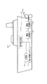
図1は、実施形態1に係る電力貯蔵システム100の構成を示す機能ブロック図である。図2は、電力貯蔵システム100を搭載した船舶300を概略的に示す図である。図1に示す電力貯蔵システム100の用途は、特に限定されず、たとえば、車両などの移動体に用いられる。この電力貯蔵システム100は、たとえば、図2に示す電気推進船舶(船舶)300の補助電源として用いられる。図2では、船舶300は、電気推進力(電動発電機330の駆動力)をプロペラ220の主駆動源として用いている。ただし、プロペラ220の主駆動源に主機(図示せず)と用いて、電気推進力(電動発電機330の駆動力)をプロペラ220の補助駆動源として用いてもよい。なお、電動発電機330は電動変換器320を介して電力貯蔵システム100、主電源310および船内電力系統210に接続している。
(Embodiment 1)
FIG. 1 is a functional block diagram illustrating a configuration of the
通常、航海中には船舶300を推進する電力および船舶300内で使用する電力を船舶300に備えられた主電源310で賄っている。この電力の変動が非常大きいと、過電流によって主電源310からの電力供給が遮断されてしまう。このような事態を回避するため、主電源310と共に補助電源として電力貯蔵システム100が船舶300の負荷200(たとえば、船内電力系統210およびプロペラ220駆動用電動発電機330)に接続されている。これにより、電力貯蔵システム100は、適宜、主電源310をアシストして電力を負荷200に供給し、または、負荷200から電力を受給して貯蔵する。ただし、電力貯蔵システム100の用途は船舶300の補助電源に限定されず、たとえば、自動車や家庭などに電力を供給する電力貯蔵システムとしても用いられる。
Normally, during voyage, the
電力貯蔵システム100は、二次電池10、キャパシタ11および制御器12を備えている。電力貯蔵システム100は、DC/ACインバータ13を介して負荷200に電力を供給し、または、負荷200から電力を受給して二次電池10およびキャパシタ11の一方または双方に貯蔵する。
The
DC/ACインバータ(電力変換器)13は、負荷側端子が負荷200に接続されている。DC/ACインバータ13は、電源側端子に入力される直流電力を交流電力に変換して、交流電力を負荷側端子から出力する。また、DC/ACインバータ13は、負荷側端子に入力される交流電力を直流電力に変換して、直流電力を電源側端子から出力する。
The DC / AC inverter (power converter) 13 has a load-side terminal connected to the
DC/ACインバータ13の電源側端子には、二次電池10とキャパシタ11とが互いに並列に接続されている。キャパシタ11は、DC/DCコンバータ17を介してDC/ACインバータ13の電源側端子に接続されている。
The
具体的には、DC/ACインバータ13の電源側端子に一対の配線で構成されるDCリンク20を介して二次電池10が接続され、このDCリンク20にキャパシタ11がDC/DCコンバータ17を介して接続されている。DCリンク20を構成する一対の配線間にはDCリンクキャパシタ14が接続されている。
Specifically, the
DCリンクキャパシタ14は、DCリンク20の電圧の変動を平滑化する。DCリンクキャパシタ14に並列に電圧センサ15が接続されている。電圧センサ15は、DCリンク20の電圧であるDCリンク電圧Vdc(DCリンクキャパシタ14の両端電圧))を検知する。
The
二次電池10は、電荷を化学反応または物理反応を介して蓄積し、蓄積した電荷を逆反応を介して放出する大容量型蓄電デバイスである。二次電池10としては、たとえば、リチウムイオン電池、ニッケル水素電池および鉛蓄電池が用いられる。二次電池10に直列に第1電流センサ16が接続されている。第1電流センサ16は、二次電池10とキャパシタ11との接続点との間に設けられており、二次電池10から放電されるまたは二次電池10を充電する電流Ibを検知する。
The
キャパシタ11は、電荷を直接(反応を介さずに)蓄積し、蓄積した電荷を直接放出する高出力型蓄電デバイスである。キャパシタ11として、たとえば、リチウムイオンキャパシタ、電気二重層キャパシタが用いられる。キャパシタ11は、DCリンク20にDC/DCコンバータ17を介して接続されており、この接続点は第1電流センサ16とDCリンクキャパシタ14との間に設けられている。
The capacitor 11 is a high-power storage device that directly accumulates charges (not via a reaction) and directly discharges the accumulated charges. As the capacitor 11, for example, a lithium ion capacitor or an electric double layer capacitor is used. The capacitor 11 is connected to the
DC/DCコンバータ17は、通流率を変化させてキャパシタ11の電流を変化させる。DC/DCコンバータ17は、電圧を変えることが可能な昇圧機能または降圧機能を有していてもよい。DC/DCコンバータ17とキャパシタ11の接続点との間においてDC/DCコンバータ17に直列に直流リアクトル18(DCL)が接続されている。直流リアクトル18は、DC/DCコンバータ17から出力されるまたはDC/DCコンバータ17に入力される電流を平滑化する。DC/DCコンバータ17とDCリンク20との間においてDC/DCコンバータ17に直列に第2電流センサ19が接続されており、第2電流センサ19はキャパシタ11から放電されるまたはキャパシタ11を充電する電流Icを検知する。
The DC /
制御器12は、二次電池10よりキャパシタ11を優先して充放電させるようにDC/DCコンバータ17を制御する。すなわち、制御器12は、第1制御部12aおよび第2制御部12bを含む。
The
第1制御部12aは、二次電池10の所定の電流指令値Ib*(二次電池電流目標値)に対する二次電池10の電流Ibの偏差に基づいて、キャパシタ11の電流指令値Ic*(キャパシタ電流目標値)を生成する。第2制御部12bは、この電流指令値Ic*に対するキャパシタ11の電流Icの偏差に基づいて、DC/DCコンバータ17の通流率Dを生成し、これをDC/DCコンバータ17に出力する。これにより、制御器12は、キャパシタ11の電流を直接的に制御し、二次電池10の電流を間接的に制御する。このため、電力貯蔵システム100の全体における電流の流れが制御される。ここで、所定の電流指令値Ib*を、0(零)または0(零)に近い値に設定する。これにより、負荷変動の際に、二次電池10の電流Ibが所定の電流指令値Ib*に抑制される。従って、所定の電流指令値Ib*に応じて、二次電池10の充放電回数が抑制され、その分、キャパシタ11が二次電池10より優先して充放電される。
Based on the deviation of the current Ib of the
第1制御部12aは、二次電池10の残存容量SOC(State Of Charge)(%)を所定値に維持するための電流Ibsoc*と、電流指令値Ib*に対する二次電池10の電流Ibの偏差とに基づいて、キャパシタ11の電流指令値Ic*を生成する。これにより、二次電池10の残存容量SOCの変動を抑制しながら、電力貯蔵システム100の全体における電流の流れを制御する。
The
次に、図1および図3を参照しながら、電力貯蔵システム100の充放電の制御方法を具体的に説明する。図3は、電力貯蔵システム100の制御器12の構成例を示すブロック図である。なお、以下の充放電では、内部起電力Eb(V)がフラットなプラトー領域で二次電池10を用いた。たとえば、残存容量SOC40%以下および60%以上で内部起電力Ebが傾く二次電池10に対しては、SOC50%付近で二次電池10を使用した。
Next, a charge / discharge control method of the
図1に示すように、DC/ACインバータ13から負荷200へ有効電力が供給されていないとき、DCリンクキャパシタ14に印加されるDCリンク電圧Vdc(V)は、二次電池10の内部起電力Eb(V)に等しくなる。この内部起電力Ebは、下記(式1)に示すように、二次電池10に残存容量SOC(State Of Charge)(%)に依存し、その関数f(SOC(t))により求められる。(式1)内の残存容量SOCは下記(式2)で表される。この(式2)におけるIbは二次電池10の電流(A)であり、Qb0はキャパシタ11の定格容量(Ah)である。
As shown in FIG. 1, when active power is not supplied from the DC /
Eb=f(SOC(t)) (式1) Eb = f (SOC (t)) (Formula 1)

一方、負荷変動が発生し、DC/ACインバータ13から負荷200へ有効電力Pac(W)が供給されると、DCリンクキャパシタ14からDC/ACインバータ13へ電流Idc(A)が流れる。この電流Idcは下記(式3)により表される。この(式3)におけるVdcはDCリンク電圧(V)である。
On the other hand, when load fluctuation occurs and active power Pac (W) is supplied from DC /
Idc=Pac/Vdc (式3)
この電流Idcの流れによって、電流Icdc(A)がDCリンクキャパシタ14から流れる。この電流Icdcは下記(式4)により表される。(式4)で、Icは、DC/DCコンバータ17の1次側(DCリンクキャパシタ14側)のキャパシタ11の電流(1次側電流)(A)である。
Idc = Pac / Vdc (Formula 3)
Due to the flow of the current Idc, a current Icdc (A) flows from the
Icdc=Idc−Ib−Ic (式4)
DCリンクキャパシタ14において電流Icdcが流れることにより、DCリンクキャパシタ14の電圧(DCリンク電圧)Vdcが降下する。DCリンク電圧Vdcは下記(式5)により表される。(式5)で、CdcはDCリンクキャパシタ14の静電容量(F)である。
Icdc = Idc-Ib-Ic (Formula 4)
When the current Icdc flows through the
Vdc=(−1/Cdc)∫Icdc・dt (式5)
DCリンク電圧Vdcの降下により、DCリンク電圧Vdcと内部起電力Ebとの電位差が生じ、二次電池10からDCリンクキャパシタ14へ放電電流Ib(A)が流れる。この時の放電電流Ibは下記(式6)により表される。(式6)で、Rbは二次電池10の内部抵抗(Ω)である。
Vdc = (− 1 / Cdc) ∫Icdc · dt (Formula 5)
Due to the drop in the DC link voltage Vdc, a potential difference between the DC link voltage Vdc and the internal electromotive force Eb occurs, and the discharge current Ib (A) flows from the
Ib=(Eb−Vdc)/Rb (式6)
そして、放電電流Ibが流れると、電流Ibを第1電流センサ16が検知して制御器12へ出力する。図3に示すように、制御器12は、第1電流センサ16からの電流Ibを得て、キャパシタ11を二次電池10に優先して充放電させて有効電力Pacを供給するように制御する。
Ib = (Eb−Vdc) / Rb (Formula 6)
When the discharge current Ib flows, the first
すなわち、有効電力Pac(t)(W)は、DC/ACインバータ13を介して二次電池10およびキャパシタ11から負荷200へ供給される。このため、有効電力Pac(t)は、下記(式7)で表されるように、二次電池10の電力Pb(t)(W)とキャパシタ11の電力Pc(t)(W)との合計値であって、0(W)より大きくなる。
That is, the active power Pac (t) (W) is supplied from the
Pac(t)=Pb(t)+Pc(t),t>0 (式7)
そして、二次電池10の電流指令値Ib*(二次電池電流目標値)を0(零)(A)に設定すると、二次電池10の電力Pb(t)が0(W)に近づく。このため、下記(式8)の関係となり、キャパシタ11が二次電池10より優先的に使用されて、有効電力Pac(t)の全部をキャパシタ11が担うことになる。なお、キャパシタ11が二次電池10より優先的に使用されれば、二次電池10の電流指令値Ib*を0(A)でなく、0(零)に近い値(A)に設定してもよい。
Pac (t) = Pb (t) + Pc (t), t> 0 (Expression 7)
When the current command value Ib * (secondary battery current target value) of the
Pac(t)=Pc(t),t>0 (式8)
そこで、第1制御部12aは、二次電池10の電流指令値Ib*に対する第1電流センサ16からの電流Ibの偏差(Ib*−Ib)からキャパシタ11の出力電力指令値Pc*(W)を下記(式9)に基づいて求める。(式9)で、C1(s)は伝達関数である。
Pac (t) = Pc (t), t> 0 (Equation 8)
Therefore, the
Pc*=C1(s)・(Ib*−Ib) (式9)
第1制御部12aは、電圧センサ15からDCリンク電圧Vdcを得る。そして、第1制御部12aは、このDCリンク電圧Vdcと(式9)で求めた出力電力指令値Pc*とからキャパシタ11の電流指令値Ic*(キャパシタ電流目標値)を下記(式10)に従って演算して得る。1次側電流指令値Ic*は、DC/DCコンバータ17の1次側(DCリンクキャパシタ14側)のキャパシタ11の電流指令値(A)である。
Pc * = C1 (s) · (Ib * −Ib) (Formula 9)
The
Ic*=Pc*/Vdc (式10)
次に、第2制御部12bは、第2電流センサ19からキャパシタ11の電流Icを得る。そして、第2制御部12bは、この電流Icの1次側電流指令値Ic*に対する偏差(Ic*−Ic)からDC/DCコンバータ17の通流率Dを下記(式11)に基づいて求める。(式11)で、C2(s)は伝達関数である。
Ic * = Pc * / Vdc (Formula 10)
Next, the
D=C2(s)・(Ic*−Ic) (式11)
第2制御部12bは、通流率DをDC/DCコンバータ17に出力すると、1次側電流Icの電流がキャパシタ11から流れる。この電流は、DC/DCコンバータ17および直流リアクトル18を介してDCリンクキャパシタ14に流れる。このDCリンクキャパシタ14に供給される電力Pc(W)は下記(式12)で表される。
D = C2 (s) · (Ic * −Ic) (Formula 11)
When the
Pc=Vdc・Ic (式12)
上記のとおり、二次電池10の電流指令値Ib*が0(零)または0(零)に近い値に設定されているため、キャパシタ11の電力Pcが有効電力Pacとして負荷200に供給される。このキャパシタ11の電力Pcが有効電力Pacに等しければ、有効電力Pacに対してキャパシタ11の電力Pcで足りているため、キャパシタ11のみで負荷200に電力を供給する。
Pc = Vdc · Ic (Formula 12)
As described above, since the current command value Ib * of the
一方、キャパシタ11の残存容量SOCの低下や出力電流の制限などによってキャパシタ11の電力Pcが有効電力Pacより小さければ、有効電力Pacに対してキャパシタ11の電力Pcで足りない。このため、DCリンク電圧Vdcが低下し、DCリンク電圧Vdcと内部起電力Ebとの電位差が生じる。これにより、二次電池10からDCリンクキャパシタ14へ放電電流Ib(A)が流れて、下記(式13)の二次電池10の電力PbがDCリンクキャパシタ14に供給される。この二次電池10の電力Pbをキャパシタ11の電力Pcに加えた電力が有効電力Pacとして負荷200に供給される。
On the other hand, if the power Pc of the capacitor 11 is smaller than the effective power Pac due to the decrease in the remaining capacity SOC of the capacitor 11 or the limitation of the output current, the power Pc of the capacitor 11 is insufficient with respect to the effective power Pac. For this reason, the DC link voltage Vdc decreases, and a potential difference between the DC link voltage Vdc and the internal electromotive force Eb occurs. As a result, the discharge current Ib (A) flows from the
Pb=Vdc・Ib (式13)
また、二次電池10の内部起電力Ebは二次電池10の残存容量SOCに依存するため、上記のとおりにキャパシタ11の電流を制御するのに加えて、二次電池10の残存容量SOCも制御する必要がある。このため、制御器12は、第1電流センサ16から二次電池10の電流Ibを取得し、二次電池10の残存容量SOC(t)を上記(式2)から求める。制御器12は、二次電池10の残存容量SOC(t)からSOC維持用の電流指令値Ibsoc*を下記(式14)に従って算出する。(式14)においてC3はSOC(t)の補正項である。そして、制御器12は、電流指令値Ibsoc*によって二次電池10の電流指令値Ib*を補正することによって、二次電池10の残存容量SOCを制御する。
Pb = Vdc · Ib (Formula 13)
Further, since the internal electromotive force Eb of the
Ibsoc*=C3・(SOC(t)) (式14)
なお、図3では、電流指令値Ibsoc*が電流指令値Ib*に加算されているが、電流指令値Ibsoc*は、電流指令値Ib*に対する電流Ibの偏差に加算されてもよい。
Ibsoc * = C3 · (SOC (t)) (Formula 14)
In FIG. 3, the current command value Ibsoc * is added to the current command value Ib * , but the current command value Ibsoc * may be added to the deviation of the current Ib from the current command value Ib * .
上記構成によれば、DC/DCコンバータ17の通流率によってキャパシタ11の電流を制御することにより、二次電池10の電流も間接的に制御し、電力貯蔵システム100の全体における電流の流れを制御することができる。よって、制御パラメータが負荷変動の特性に依存することがなく、電力貯蔵システム100は汎用性に優れている。
According to the above configuration, the current of the
また、二次電池10よりキャパシタ11を優先して充放電させている。これにより、二次電池10の充放電回数および充放電深度を減らすことができるため、二次電池10の長寿命化を図ることができる。
Further, the capacitor 11 is charged and discharged with priority over the
たとえば、二次電池10の電流指令値Ib*を0または0に近い値に設定している。これにより、キャパシタ11を二次電池10より優先的に簡単に充放電させることができる。
For example, the current command value Ib * of the
なお、二次電池10の充放電時の電流Ibが低いほど、二次電池10の長寿命化が図られる。このため、二次電池10の電流指令値Ib*の0(零)に近い値に、たとえば、二次電池10の一時間電流率以下の電流値に設定してもよい。この一時間電流率は、一時間で二次電池の残存容量SOC(State Of Charge)を0%から100%まで充電することができる電流値、または、一時間で二次電池のSOCを100%から0%まで放電することができる電流値である。このように、二次電池10の充放電電流Ibが一時間電流率(1C)以下に制限される。これにより、キャパシタ11より大きな電流が二次電池10に流れることによって二次電池10の劣化が促進されることを抑制することができ、二次電池10の長寿命化が図られる。
In addition, the lifetime of the
また、二次電池10の電流指令値Ib*の0(零)に近い値を、有効電力Pacおよび比例係数kを用いて、Ib*=k・Pacと第1制御部12aにおいて設定してもよい。これにより、電力貯蔵システム100全体の出力に比例して、二次電池10の電流Ibを増減させることができる。このとき、二次電池10とキャパシタ11との負荷分担率はk:(1−k)となるため、比例係数kによって二次電池10の負荷分担率を調整することが可能である。よって、放電中にキャパシタ11のSOCが規定値以下になった場合、または、充電中にキャパシタ11のSOCが規定値以上になった場合、キャパシタ11の電流指令値Ic*を低減して、二次電池10の充放電電流Ibが増加させることができる。
Further, even if a value close to 0 (zero) of the current command value Ib * of the
(実施例)
次に、上記構成の電力貯蔵システム100における二次電池10の長寿命化について実施例による検証結果を説明する。具体的には、二次電池10の寿命は二次電池10の発熱量に依存する。二次電池10の発熱量が大きいほど、二次電池10が劣化し、二次電池10の寿命が短くなる。よって、充放電パターンに応じて電力貯蔵システム100を制御した際の二次電池10の発熱量に基づいて二次電池10の寿命を評価した。
(Example)
Next, the verification result by an Example about the lifetime improvement of the
実施例の電力貯蔵システム100では、図3に示す制御例の通りに二次電池10の電流指令値ib*=0とし、各センサ16、19、15からの検出値Ib、Ic、Vdcに基づいて求めたDC/DCコンバータ17の通流率Dにより、キャパシタ11の電流を制御した。一方、比較例の電源システムでは、上記非特許文献1のハイブリッド電源システムと同様に、比例補償器を用い、高周波成分をHPF(High Pass Filter)で分離して、低周波成分の電力を二次電池10が供給し、高い周波数成分の電力を電気二重層キャパシタ11が供給した。ここで、キャパシタ11をできる限り使用するように、HPFの時定数TEDLCを充放電パターンの周期より大きく、比例補償器の比例ゲインkpをキャパシタ11の上限電圧および下限電圧に達しない範囲における小さい値に設定した。このため、充放電パターンの周期および電圧に応じて時定数TEDLCおよび比例ゲインkpは異なる。
In the
なお、実施例の電力貯蔵システム100および比較例の電源システムの構成(二次電池10およびキャパシタ11の各数量、各内部抵抗、静電容量など)、ならびに、DC/DCコンバータ17の制御方法およびパラメータをそれぞれ同一にした。実施例の電力貯蔵システム100および比較例の電源システムでは、キャパシタ11の損失を十分補償できるように、二次電池10の二次電池10容量を155.52kWhとした。また、キャパシタ11の初期電力量を2.15kWhとした。
In addition, the configuration of the
検証では、電力の大きさおよび充放電の周波数が異なる2種類の充放電パターンに従って、実施例の電力貯蔵システム100および比較例の電源システムを制御した。そして、二次電池10の損失量(内部損失)の全てまたはほぼ全てが熱エネルギになるため、損失量Loss(kWh)を発熱量として下記(式15)により求めた。この(式15)において、iは二次電池10の電流(A)であり、Rは二次電池10の内部抵抗(Ω)である。
In the verification, the
Loss=(3600/1000)・∫i2・Rdt (式15)
第1充放電パターンでは、図4に示すように、5秒間250kWの電力量(0.347kWh)を放電し、1秒間休止した後、5秒間250kWを充電し、1秒間休止するという周期12秒の充放電を繰り返す。第2充放電パターンでは、図5に示すように、15秒間500kWの電力量(2.083kWh)を放電し、2秒間休止した後、15秒間500kWを充電し、2秒間休止するという周期34秒の充放電を繰り返す。このように、第1充放電パターンの電力量(0.347kWh)がキャパシタ11の初期電力量(2.15kWh)より非常に小さいため、第1充放電パターンはキャパシタ11に対して軽充放電と言える。第2充放電パターンの電力量(2.083kWh)がキャパシタ11の初期電力量(2.15kWh)と同等であるため、第2充放電パターンはキャパシタ11に対して重充放電と言える。
Loss = (3600/1000) · ∫i 2 · Rdt (Formula 15)
In the first charge / discharge pattern, as shown in FIG. 4, a period of 12 seconds in which 250 kW of electric energy (0.347 kWh) is discharged for 5 seconds, paused for 1 second, charged for 250 seconds for 5 seconds, and paused for 1 second. Repeat charging and discharging. In the second charge / discharge pattern, as shown in FIG. 5, a period of 34 seconds in which 500 kW of electric power (2.083 kWh) is discharged for 15 seconds, paused for 2 seconds, charged 500 kW for 15 seconds, and paused for 2 seconds. Repeat charging and discharging. Thus, since the electric energy (0.347 kWh) of the first charge / discharge pattern is much smaller than the initial electric energy (2.15 kWh) of the capacitor 11, the first charge / discharge pattern is lightly charged / discharged with respect to the capacitor 11. I can say that. Since the electric energy (2.083 kWh) of the second charge / discharge pattern is equivalent to the initial electric energy (2.15 kWh) of the capacitor 11, it can be said that the second charge / discharge pattern is heavy charge / discharge with respect to the capacitor 11.
検証の結果、図6に示すように、第1充放電パターンで充放電した際、実施例および比較例の損失量Lossは時間の経過と伴に増加している。また、図7に示すように、第2充放電パターンで充放電した際、実施例および比較例の損失量Lossは時間の経過と伴に増加している。図6および図7の全時間範囲において実施例の損失量は比較例の損失量より小さく、この差は時間の経過と伴に大きくなっている。 As a result of the verification, as shown in FIG. 6, when charging / discharging with the first charging / discharging pattern, the loss amount Loss of the example and the comparative example increases with time. Moreover, as shown in FIG. 7, when charging / discharging by the 2nd charging / discharging pattern, the loss amount Loss of an Example and a comparative example is increasing with progress of time. 6 and 7, the loss amount of the example is smaller than the loss amount of the comparative example, and this difference increases with the passage of time.
また、図6の1200(sec)時点における実施例の損失量は比較例の損失量の72.2%であった。図7の1200(sec)時点における実施例の損失量は比較例の損失量の51.3%であった。 Further, the loss amount of the example at 1200 (sec) in FIG. 6 was 72.2% of the loss amount of the comparative example. The loss amount of the example at 1200 (sec) in FIG. 7 was 51.3% of the loss amount of the comparative example.
このように、実施例の損失量は比較例より小さいことから、実施例の発熱量が比較例より少ない。このため、実施例における二次電池10の熱劣化が抑制され、二次電池10の長寿命化が図れたと考えられる。
Thus, since the loss amount of an Example is smaller than a comparative example, the emitted-heat amount of an Example is less than a comparative example. For this reason, it is thought that the thermal deterioration of the
このような実施例の損失量と比較例の損失量との差は、二次電池10の電力(kWh)および二次電池10の電流(A)に由来する。すなわち、図8(a)に示すように、第2充放電パターンで実施例が充放電した際、負荷200への放電開始時にはキャパシタ11のみから電力を供給し、これによりキャパシタ11の残量容量が減少するに従って二次電池10からも電力を供給する。次に、休止中には二次電池10からの給電が終了し、充電時にはキャパシタ11のみに電力が供給される。また、図8(b)に示す電流についても、図8(a)の電力と同様のことが言える。つまり、第2充放電パターンによる実施例の充放電では、放電の初期にはキャパシタ11のみから電流が流れ、キャパシタ11の残量容量が減少するに伴って二次電池10からも電流が流れる。そして、休止中に二次電池10からの電流の流れが終わり、充電時にはキャパシタ11のみに電流が流れる。
The difference between the loss amount of the example and the loss amount of the comparative example is derived from the power (kWh) of the
一方、図9(a)に示すように、第2充放電パターンで比較例が充放電した際、放電が始まると、HPFによって高周波成分の電力をキャパシタ11のみから供給し、その後の低周波成分の電力を二次電池10およびキャパシタ11から供給している。充電が終了すると(20秒付近、50秒付近)、キャパシタ11の残存容量SOCを回復するために比例補償器が働き、二次電池10からキャパシタ11に電力が供給される。そして、充電の終了時から放電開示時(35秒付近、70秒付近)に、キャパシタ11の残存容量SOCが上限に近くなるため、負荷200からの電力が二次電池10に供給される。また、図9(b)に示す電流についても、図9(a)の電力と同様のことが言える。つまり、第2充放電パターンによる比較例の充放電では、放電の初期にキャパシタ11のみから電流が流れ、その後に二次電池10からも電流が流れる。そして、休止中および充電と途中まで二次電池10から電流が流れ、充電時にはキャパシタ11へ電流が流れ、充電の途中からは二次電池10へも電流が流れる。
On the other hand, as shown in FIG. 9A, when the comparative example is charged / discharged with the second charge / discharge pattern, when discharge starts, high-frequency component power is supplied from the capacitor 11 only by the HPF, and the subsequent low-frequency component. Is supplied from the
このように、比較例の電源システムでは、HPFの機能によってキャパシタ11の残存容量SOCが急激に増減するのに対してキャパシタ11の電力指令値を補償するように比例補償器が働く。これにより、放電中のみならず充電中も二次電池10の電流が常時流れている。これに対して、実施例では、二次電池10の電流指令値ib*=0(A)にすることにより、電流指令値ib*と二次電池10の電流Ibとの偏差に相当するキャパシタ11の出力電力指令値Pc*が決定されるため、二次電池10からキャパシタ11に電力が供給されない。このように、実施例では効率的に電力がキャパシタ11のみに充電される。よって、比較例のような二次電池10とキャパシタ11との間の電力のやり取りが実施例では行われないことにより、実施例の損失量(発熱量)は比較例に比べて小さくなる。
As described above, in the power supply system of the comparative example, the proportional compensator works so as to compensate the power command value of the capacitor 11 against the sudden increase / decrease in the remaining capacity SOC of the capacitor 11 due to the HPF function. Thereby, the current of the
なお、図10に示す第2充放電パターンで1200秒間、充放電した際の実施例の二次電池10の残存容量SOC(%)は、38.9%であった。また、図11に示す第2充放電パターンで1200秒間、充放電した際の比較例の二次電池10の残存容量SOC(%)は、37.5%であった。このため、実施例の二次電池10の残存容量SOCは比較例と同等であった。なお、充放電開始時における実施例および比較例の各二次電池10の残存容量SOCは、50%であった。
Note that the remaining capacity SOC (%) of the
(その他の実施の形態)
なお、上記実施の形態において、負荷200に直流電力を供給する場合には、電力変換器として、DC/ACインバータ13に代えて、DC/DCコンバータを用いてもよい。
(Other embodiments)
In the above embodiment, when DC power is supplied to the
上記説明から、当業者にとっては、本発明の多くの改良や他の実施形態が明らかである。従って、上記説明は、例示としてのみ解釈されるべきであり、本発明を実行する最良の態様を当業者に教示する目的で提供されたものである。本発明の精神を逸脱することなく、その構造および/又は機能の詳細を実質的に変更できる。 From the foregoing description, many modifications and other embodiments of the present invention are obvious to one skilled in the art. Accordingly, the foregoing description should be construed as illustrative only and is provided for the purpose of teaching those skilled in the art the best mode of carrying out the invention. The details of the structure and / or function may be substantially changed without departing from the spirit of the invention.
本発明の電力貯蔵システムおよびその制御方法は、汎用性が高く、長寿命化が図られた電力貯蔵システムおよびその制御方法等として有用である。 The power storage system and the control method thereof of the present invention are useful as a power storage system and a control method thereof having high versatility and a long life.
10 二次電池
11 キャパシタ
12 制御器
12a 第1制御部
12b 第2制御部
13 DC/ACインバータ
14 DCリンクキャパシタ
17 DC/DCコンバータ
20 DCリンク
100 電力貯蔵システム
200 負荷
DESCRIPTION OF
Claims (3)
前記電力変換器の電源側端子に接続された二次電池と、
前記電力変換器の電源側端子にDC/DCコンバータを介して前記二次電池に並列に接続されたキャパシタと、
前記二次電池より前記キャパシタを優先して充放電させるように前記DC/DCコンバータを制御する制御器と、を備え、
前記制御器は、
零または零に近い所定の二次電池電流目標値に対する前記二次電池の電流の偏差に基づいて前記キャパシタ電流目標値を生成する第1制御部と、
前記キャパシタ電流目標値に対する前記キャパシタの電流の偏差に基づいて前記DC/DCコンバータの通流率を生成し、これを前記DC/DCコンバータに出力する第2制御部と、を含み、
零に近い所定の二次電池電流目標値は、前記二次電池の一時間電流率以下の電流値である、電力貯蔵システム。 A power converter with a load-side terminal connected to the load;
A secondary battery connected to the power supply side terminal of the power converter;
A capacitor connected in parallel to the secondary battery via a DC / DC converter to a power supply side terminal of the power converter;
A controller for controlling the DC / DC converter so as to charge and discharge the capacitor with priority over the secondary battery ,
The controller is
A first control unit that generates the capacitor current target value based on a deviation of the current of the secondary battery with respect to a predetermined secondary battery current target value that is zero or close to zero;
A second control unit that generates a conduction ratio of the DC / DC converter based on a deviation of the current of the capacitor with respect to the capacitor current target value, and outputs this to the DC / DC converter;
The power storage system , wherein the predetermined secondary battery current target value close to zero is a current value equal to or less than an hourly current rate of the secondary battery .
前記制御器は、
零または零に近い所定の二次電池電流目標値に対する前記二次電池の電流の偏差に基づいて前記キャパシタ電流目標値を生成し、
前記キャパシタ電流目標値に対する前記キャパシタの電流の偏差に基づいて前記DC/DCコンバータの通流率を生成し、これを前記DC/DCコンバータに出力して、
前記二次電池より前記キャパシタを優先して充放電させるように前記DC/DCコンバータを制御し、
零に近い所定の二次電池電流目標値は、前記二次電池の一時間電流率以下の電流値である、電力貯蔵システムの制御方法。 A power converter having a load side terminal connected to a load; a secondary battery connected to a power source side terminal of the power converter; and a secondary battery connected to a power source side terminal of the power converter via a DC / DC converter. A method for controlling an electric power storage system comprising a capacitor connected in parallel to a battery and a controller,
The controller is
Generating the capacitor current target value based on a deviation of the current of the secondary battery with respect to a predetermined secondary battery current target value of zero or near zero;
Based on the deviation of the current of the capacitor with respect to the target value of the capacitor current, a conduction ratio of the DC / DC converter is generated and output to the DC / DC converter.
Controlling the DC / DC converter to charge and discharge the capacitor in preference to the secondary battery ;
The power storage system control method , wherein the predetermined secondary battery current target value close to zero is a current value equal to or less than an hourly current rate of the secondary battery .
Priority Applications (6)
| Application Number | Priority Date | Filing Date | Title |
|---|---|---|---|
| JP2014120288A JP6496496B2 (en) | 2014-06-11 | 2014-06-11 | Power storage system and control method thereof |
| US15/318,304 US10263448B2 (en) | 2014-06-11 | 2015-06-10 | Power storage system and method of controlling the same |
| EP15806373.5A EP3157132B1 (en) | 2014-06-11 | 2015-06-10 | Hybrid electrical energy storage system and method for controlling same |
| CN201580030874.4A CN106464000B (en) | 2014-06-11 | 2015-06-10 | Electric power storage system and its control method |
| CA2916461A CA2916461C (en) | 2014-06-11 | 2015-06-10 | Power storage system and method of controlling the same |
| PCT/JP2015/002905 WO2015190094A1 (en) | 2014-06-11 | 2015-06-10 | Electrical energy storage system and method for controlling same |
Applications Claiming Priority (1)
| Application Number | Priority Date | Filing Date | Title |
|---|---|---|---|
| JP2014120288A JP6496496B2 (en) | 2014-06-11 | 2014-06-11 | Power storage system and control method thereof |
Publications (3)
| Publication Number | Publication Date |
|---|---|
| JP2016001936A JP2016001936A (en) | 2016-01-07 |
| JP2016001936A5 JP2016001936A5 (en) | 2017-07-06 |
| JP6496496B2 true JP6496496B2 (en) | 2019-04-03 |
Family
ID=54833205
Family Applications (1)
| Application Number | Title | Priority Date | Filing Date |
|---|---|---|---|
| JP2014120288A Active JP6496496B2 (en) | 2014-06-11 | 2014-06-11 | Power storage system and control method thereof |
Country Status (6)
| Country | Link |
|---|---|
| US (1) | US10263448B2 (en) |
| EP (1) | EP3157132B1 (en) |
| JP (1) | JP6496496B2 (en) |
| CN (1) | CN106464000B (en) |
| CA (1) | CA2916461C (en) |
| WO (1) | WO2015190094A1 (en) |
Families Citing this family (11)
| Publication number | Priority date | Publication date | Assignee | Title |
|---|---|---|---|---|
| JP6781550B2 (en) * | 2016-02-01 | 2020-11-04 | 川崎重工業株式会社 | Power storage system and its control method |
| JP2017139844A (en) | 2016-02-01 | 2017-08-10 | 川崎重工業株式会社 | Electric power storage unit |
| TWM538649U (en) * | 2016-02-04 | 2017-03-21 | Kai Si Rong Co Ltd | Power supply device with capacitor of high capacity of electric energy |
| CN105703435B (en) * | 2016-03-22 | 2019-06-11 | 深圳市德利和能源技术有限公司 | Energy-storage system |
| US11065979B1 (en) | 2017-04-05 | 2021-07-20 | H55 Sa | Aircraft monitoring system and method for electric or hybrid aircrafts |
| US11148819B2 (en) | 2019-01-23 | 2021-10-19 | H55 Sa | Battery module for electrically-driven aircraft |
| US11063323B2 (en) | 2019-01-23 | 2021-07-13 | H55 Sa | Battery module for electrically-driven aircraft |
| US10322824B1 (en) | 2018-01-25 | 2019-06-18 | H55 Sa | Construction and operation of electric or hybrid aircraft |
| EP3743974A1 (en) * | 2018-01-25 | 2020-12-02 | H55 Sa | Electrical powering or drive system for a motor in an electrically driven aircraft |
| WO2020044601A1 (en) * | 2018-08-31 | 2020-03-05 | 川崎重工業株式会社 | Battery-electric propulsion ship power feeding system, offshore power feeding facility, and battery-electric propulsion ship |
| WO2020208527A1 (en) | 2019-04-08 | 2020-10-15 | H55 Sa | Power supply storage and fire management in electrically-driven aircraft |
Family Cites Families (12)
| Publication number | Priority date | Publication date | Assignee | Title |
|---|---|---|---|---|
| JP3430709B2 (en) * | 1995-04-28 | 2003-07-28 | いすゞ自動車株式会社 | Electric vehicle power control device |
| JP2900309B2 (en) * | 1996-08-30 | 1999-06-02 | 日晴金属株式会社 | Electric vehicle regeneration system |
| JP2002095174A (en) * | 2000-09-13 | 2002-03-29 | Casio Comput Co Ltd | Power system and its charging method |
| US7791216B2 (en) * | 2004-11-01 | 2010-09-07 | Ford Global Technologies, Llc | Method and system for use with a vehicle electric storage system |
| JP4866764B2 (en) * | 2007-03-12 | 2012-02-01 | 清水建設株式会社 | Control method of distributed power supply |
| US20100181828A1 (en) * | 2007-07-25 | 2010-07-22 | Panasonic Corporation | Electric power source device for vehicle |
| JP2010288414A (en) * | 2009-06-15 | 2010-12-24 | Toyota Motor Corp | Power supply device for vehicle |
| JP5189607B2 (en) * | 2010-02-04 | 2013-04-24 | トヨタ自動車株式会社 | Vehicle power supply |
| JP5318004B2 (en) * | 2010-03-01 | 2013-10-16 | 三菱電機株式会社 | Vehicle power supply system |
| CN103052527B (en) * | 2010-08-02 | 2015-02-11 | 松下电器产业株式会社 | Vehicle power source device |
| JP2014060890A (en) * | 2012-09-19 | 2014-04-03 | Kuzumi Denshi Kogyo Kk | Power supply device |
| CN104769827B (en) * | 2012-11-07 | 2017-11-21 | 沃尔沃卡车公司 | Supply unit |
-
2014
- 2014-06-11 JP JP2014120288A patent/JP6496496B2/en active Active
-
2015
- 2015-06-10 CN CN201580030874.4A patent/CN106464000B/en active Active
- 2015-06-10 US US15/318,304 patent/US10263448B2/en active Active
- 2015-06-10 CA CA2916461A patent/CA2916461C/en active Active
- 2015-06-10 WO PCT/JP2015/002905 patent/WO2015190094A1/en active Application Filing
- 2015-06-10 EP EP15806373.5A patent/EP3157132B1/en active Active
Also Published As
| Publication number | Publication date |
|---|---|
| CA2916461C (en) | 2016-11-01 |
| US20170126025A1 (en) | 2017-05-04 |
| WO2015190094A1 (en) | 2015-12-17 |
| CN106464000A (en) | 2017-02-22 |
| CN106464000B (en) | 2019-04-16 |
| EP3157132A1 (en) | 2017-04-19 |
| EP3157132B1 (en) | 2019-11-20 |
| JP2016001936A (en) | 2016-01-07 |
| CA2916461A1 (en) | 2015-12-17 |
| EP3157132A4 (en) | 2018-02-21 |
| US10263448B2 (en) | 2019-04-16 |
Similar Documents
| Publication | Publication Date | Title |
|---|---|---|
| JP6496496B2 (en) | Power storage system and control method thereof | |
| WO2015129117A1 (en) | Soc estimation device for secondary battery | |
| JP5381026B2 (en) | Control circuit for composite power supply | |
| JP5546649B2 (en) | Vehicle power supply system | |
| US9956888B2 (en) | Power supply system | |
| US11427179B2 (en) | Power supply system | |
| US10576835B2 (en) | Energy storage device, transport apparatus, and control method | |
| JP6313522B2 (en) | Power control apparatus and power control system | |
| JP2019016571A (en) | Composite power storage system | |
| CN107592953B (en) | Charge/discharge control device, mobile body, and power share determination method | |
| JP2019129555A (en) | Dc/dc converter, power supply system, and charging/discharging method of secondary battery | |
| JP6358376B2 (en) | Storage battery conversion device, power supply system, and power supply control method | |
| JP5543018B2 (en) | Vehicle power supply system | |
| JP2012249348A (en) | Power supply control system | |
| JP6698169B2 (en) | Storage battery system | |
| JP6485871B2 (en) | Fuel cell system | |
| JP6034734B2 (en) | Power system | |
| JP6611118B2 (en) | Power converter and industrial machine using the same | |
| JP2019169998A (en) | Power supply device | |
| JP2016063724A (en) | vehicle | |
| JP5262727B2 (en) | DC power supply control method and mobile vehicle using the DC power supply control method | |
| JP2015211608A (en) | Power conversion unit and ripple suppression control method in power conversion | |
| JP2009124888A (en) | Power supply for moving vehicles |
Legal Events
| Date | Code | Title | Description |
|---|---|---|---|
| A521 | Request for written amendment filed |
Free format text: JAPANESE INTERMEDIATE CODE: A523 Effective date: 20170523 |
|
| A621 | Written request for application examination |
Free format text: JAPANESE INTERMEDIATE CODE: A621 Effective date: 20170523 |
|
| A131 | Notification of reasons for refusal |
Free format text: JAPANESE INTERMEDIATE CODE: A131 Effective date: 20180807 |
|
| A521 | Request for written amendment filed |
Free format text: JAPANESE INTERMEDIATE CODE: A523 Effective date: 20180926 |
|
| TRDD | Decision of grant or rejection written | ||
| A01 | Written decision to grant a patent or to grant a registration (utility model) |
Free format text: JAPANESE INTERMEDIATE CODE: A01 Effective date: 20190305 |
|
| A61 | First payment of annual fees (during grant procedure) |
Free format text: JAPANESE INTERMEDIATE CODE: A61 Effective date: 20190311 |
|
| R150 | Certificate of patent or registration of utility model |
Ref document number: 6496496 Country of ref document: JP Free format text: JAPANESE INTERMEDIATE CODE: R150 |
|
| R250 | Receipt of annual fees |
Free format text: JAPANESE INTERMEDIATE CODE: R250 |