JP6252911B2 - Method and system for forming carbon nanotubes - Google Patents
Method and system for forming carbon nanotubes Download PDFInfo
- Publication number
- JP6252911B2 JP6252911B2 JP2014547386A JP2014547386A JP6252911B2 JP 6252911 B2 JP6252911 B2 JP 6252911B2 JP 2014547386 A JP2014547386 A JP 2014547386A JP 2014547386 A JP2014547386 A JP 2014547386A JP 6252911 B2 JP6252911 B2 JP 6252911B2
- Authority
- JP
- Japan
- Prior art keywords
- stream
- reactor
- feed
- gas stream
- waste gas
- Prior art date
- Legal status (The legal status is an assumption and is not a legal conclusion. Google has not performed a legal analysis and makes no representation as to the accuracy of the status listed.)
- Expired - Fee Related
Links
Images


Classifications
-
- C—CHEMISTRY; METALLURGY
- C01—INORGANIC CHEMISTRY
- C01B—NON-METALLIC ELEMENTS; COMPOUNDS THEREOF; METALLOIDS OR COMPOUNDS THEREOF NOT COVERED BY SUBCLASS C01C
- C01B32/00—Carbon; Compounds thereof
- C01B32/15—Nano-sized carbon materials
- C01B32/158—Carbon nanotubes
- C01B32/16—Preparation
-
- B—PERFORMING OPERATIONS; TRANSPORTING
- B01—PHYSICAL OR CHEMICAL PROCESSES OR APPARATUS IN GENERAL
- B01J—CHEMICAL OR PHYSICAL PROCESSES, e.g. CATALYSIS OR COLLOID CHEMISTRY; THEIR RELEVANT APPARATUS
- B01J8/00—Chemical or physical processes in general, conducted in the presence of fluids and solid particles; Apparatus for such processes
- B01J8/18—Chemical or physical processes in general, conducted in the presence of fluids and solid particles; Apparatus for such processes with fluidised particles
- B01J8/24—Chemical or physical processes in general, conducted in the presence of fluids and solid particles; Apparatus for such processes with fluidised particles according to "fluidised-bed" technique
-
- B—PERFORMING OPERATIONS; TRANSPORTING
- B82—NANOTECHNOLOGY
- B82Y—SPECIFIC USES OR APPLICATIONS OF NANOSTRUCTURES; MEASUREMENT OR ANALYSIS OF NANOSTRUCTURES; MANUFACTURE OR TREATMENT OF NANOSTRUCTURES
- B82Y30/00—Nanotechnology for materials or surface science, e.g. nanocomposites
-
- D—TEXTILES; PAPER
- D01—NATURAL OR MAN-MADE THREADS OR FIBRES; SPINNING
- D01F—CHEMICAL FEATURES IN THE MANUFACTURE OF ARTIFICIAL FILAMENTS, THREADS, FIBRES, BRISTLES OR RIBBONS; APPARATUS SPECIALLY ADAPTED FOR THE MANUFACTURE OF CARBON FILAMENTS
- D01F9/00—Artificial filaments or the like of other substances; Manufacture thereof; Apparatus specially adapted for the manufacture of carbon filaments
- D01F9/08—Artificial filaments or the like of other substances; Manufacture thereof; Apparatus specially adapted for the manufacture of carbon filaments of inorganic material
- D01F9/12—Carbon filaments; Apparatus specially adapted for the manufacture thereof
- D01F9/127—Carbon filaments; Apparatus specially adapted for the manufacture thereof by thermal decomposition of hydrocarbon gases or vapours or other carbon-containing compounds in the form of gas or vapour, e.g. carbon monoxide, alcohols
- D01F9/1271—Alkanes or cycloalkanes
- D01F9/1272—Methane
-
- D—TEXTILES; PAPER
- D01—NATURAL OR MAN-MADE THREADS OR FIBRES; SPINNING
- D01F—CHEMICAL FEATURES IN THE MANUFACTURE OF ARTIFICIAL FILAMENTS, THREADS, FIBRES, BRISTLES OR RIBBONS; APPARATUS SPECIALLY ADAPTED FOR THE MANUFACTURE OF CARBON FILAMENTS
- D01F9/00—Artificial filaments or the like of other substances; Manufacture thereof; Apparatus specially adapted for the manufacture of carbon filaments
- D01F9/08—Artificial filaments or the like of other substances; Manufacture thereof; Apparatus specially adapted for the manufacture of carbon filaments of inorganic material
- D01F9/12—Carbon filaments; Apparatus specially adapted for the manufacture thereof
- D01F9/127—Carbon filaments; Apparatus specially adapted for the manufacture thereof by thermal decomposition of hydrocarbon gases or vapours or other carbon-containing compounds in the form of gas or vapour, e.g. carbon monoxide, alcohols
- D01F9/1278—Carbon monoxide
-
- Y—GENERAL TAGGING OF NEW TECHNOLOGICAL DEVELOPMENTS; GENERAL TAGGING OF CROSS-SECTIONAL TECHNOLOGIES SPANNING OVER SEVERAL SECTIONS OF THE IPC; TECHNICAL SUBJECTS COVERED BY FORMER USPC CROSS-REFERENCE ART COLLECTIONS [XRACs] AND DIGESTS
- Y02—TECHNOLOGIES OR APPLICATIONS FOR MITIGATION OR ADAPTATION AGAINST CLIMATE CHANGE
- Y02P—CLIMATE CHANGE MITIGATION TECHNOLOGIES IN THE PRODUCTION OR PROCESSING OF GOODS
- Y02P20/00—Technologies relating to chemical industry
- Y02P20/10—Process efficiency
- Y02P20/129—Energy recovery, e.g. by cogeneration, H2recovery or pressure recovery turbines
-
- Y—GENERAL TAGGING OF NEW TECHNOLOGICAL DEVELOPMENTS; GENERAL TAGGING OF CROSS-SECTIONAL TECHNOLOGIES SPANNING OVER SEVERAL SECTIONS OF THE IPC; TECHNICAL SUBJECTS COVERED BY FORMER USPC CROSS-REFERENCE ART COLLECTIONS [XRACs] AND DIGESTS
- Y02—TECHNOLOGIES OR APPLICATIONS FOR MITIGATION OR ADAPTATION AGAINST CLIMATE CHANGE
- Y02P—CLIMATE CHANGE MITIGATION TECHNOLOGIES IN THE PRODUCTION OR PROCESSING OF GOODS
- Y02P70/00—Climate change mitigation technologies in the production process for final industrial or consumer products
- Y02P70/50—Manufacturing or production processes characterised by the final manufactured product
- Y02P70/62—Manufacturing or production processes characterised by the final manufactured product related technologies for production or treatment of textile or flexible materials or products thereof, including footwear
Landscapes
- Chemical & Material Sciences (AREA)
- Engineering & Computer Science (AREA)
- Nanotechnology (AREA)
- Physics & Mathematics (AREA)
- Materials Engineering (AREA)
- Chemical Kinetics & Catalysis (AREA)
- Organic Chemistry (AREA)
- General Chemical & Material Sciences (AREA)
- Textile Engineering (AREA)
- Thermal Sciences (AREA)
- Inorganic Chemistry (AREA)
- Condensed Matter Physics & Semiconductors (AREA)
- General Physics & Mathematics (AREA)
- Composite Materials (AREA)
- Crystallography & Structural Chemistry (AREA)
- Combustion & Propulsion (AREA)
- Carbon And Carbon Compounds (AREA)
Description
〔関連出願〕
本出願は、2011年12月12日出願のDenton及びNoyesによる「カーボンナノチューブを形成する方法及びシステム(Methods and System for Forming Carbon Nanotubes)」という名称の米国特許仮出願第61/569,494号、及び2011年12月30日出願のDenton及びNoyesによる「カーボンナノチューブを形成する方法及びシステム(Methods and System for Forming Carbon Nanotubes)」という名称の米国特許仮出願第61/582,098号に対する優先権を主張するものである。
[Related applications]
This application is a US Provisional Application No. 61 / 569,494 entitled “Methods and Systems for Forming Carbon Nanotubes” by Denton and Noyes filed December 12, 2011, And US Patent Provisional Application No. 61 / 582,098 entitled “Methods and Systems for Forming Carbon Nanotubes” by Denton and Noyes filed Dec. 30, 2011. It is what I insist.
本発明の技術は、カーボンファイバ及びカーボンナノ材料を形成するための産業規模プロセスに関する。 The technology of the present invention relates to an industrial scale process for forming carbon fibers and carbon nanomaterials.
本項は、本発明の技術の例示的な実施形態と関係する可能性がある当業技術の様々な態様を紹介するように意図したものである。本解説は、本発明の技術の特定の態様のより明快な理解を容易にするためのフレームを与えるのに役立つものと考えられる。従って、本項は、この点に鑑みて、かつ必ずしも従来技術の自認としてではなく読解しなければならないことを理解すべきである。 This section is intended to introduce various aspects of the technology that may be related to exemplary embodiments of the technology of the present invention. This discussion is believed to be helpful in providing a frame to facilitate a clearer understanding of certain aspects of the technology of the present invention. Therefore, it should be understood that this section should be read in light of this and not necessarily as a prior art admission.
主に固体炭素又は元素炭素で形成された材料は、長年にわたって多くの製品に使用されている。例えば、カーボンブラックは、自動車のタイヤのようなゴム製品及びプラスチック製品における顔料及び補強化合物として使用される炭素高含有材料である。通常、カーボンブラックは、メタン又は重芳香族油のような炭化水素の不完全熱分解によって形成される。天然ガスの熱分解によって形成されるサーマルブラックは、例えば、サイズが取りわけ200〜500nmの範囲にある大きい非凝集粒子を含む。重油の熱分解によって形成されるファーネスブラックは、凝集又は互いに接着して構造を形成するサイズが10〜100nmの範囲にある遙かに小さい粒子を含む。両方の場合に、これらの粒子は、開放端部又は縁部を有するグラフェンシートの層から形成することができる。化学的には、開放縁部は、吸収及び母材内への結合などに対して使用することができる反応性区域を形成する。 Materials made primarily of solid or elemental carbon have been used in many products for many years. For example, carbon black is a high carbon content material used as a pigment and reinforcing compound in rubber and plastic products such as automobile tires. Usually, carbon black is formed by incomplete pyrolysis of hydrocarbons such as methane or heavy aromatic oils. Thermal black formed by pyrolysis of natural gas includes, for example, large non-agglomerated particles that are particularly in the range of 200-500 nm in size. Furnace black formed by pyrolysis of heavy oil contains much smaller particles with a size in the range of 10 to 100 nm that aggregate or adhere to each other to form a structure. In both cases, these particles can be formed from a layer of graphene sheet having an open end or edge. Chemically, the open edge forms a reactive zone that can be used for absorption and bonding into the matrix.
フラーレンのようなより最近の形態の元素炭素が開発されており、かつ商業用途に開発され始めている。カーボンブラックのより開放した構造とは対照的に、フラーレンは、閉鎖グラフェン構造、すなわち、縁部が他の縁部に結合されて球体及びチューブなどを形成する炭素から形成される。カーボンナノファイバ及びカーボンナノチューブという2つの構造は、バッテリ及び電子機器から建築産業におけるコンクリート内での使用に至るまで多くの潜在的な用途を有する。カーボンナノ材料は、グラフェンの単一壁又はグラフェンの複数の入れ子壁を有するか、又はカップ形態又は板形態にある積み重ったシートの組からファイバ構造を形成することができる。カーボンナノチューブの端部は、多くの場合に、フラーレン状の構成に半球構造で閉蓋される。カーボンブラックの場合とは異なり、カーボンナノ材料に対する大規模生産プロセスは実施されていない。しかし、いくつかの提案されている生産プロセスに関わる研究は行われている。 More recent forms of elemental carbon such as fullerenes have been developed and are beginning to be developed for commercial use. In contrast to the more open structure of carbon black, fullerenes are formed from closed graphene structures, ie, carbon whose edges are bonded to other edges to form spheres, tubes, and the like. The two structures carbon nanofibers and carbon nanotubes have many potential applications ranging from batteries and electronics to use in concrete in the building industry. Carbon nanomaterials can have a single wall of graphene or multiple nested walls of graphene, or form a fiber structure from a set of stacked sheets in cup or plate form. The ends of the carbon nanotubes are often closed with a hemispherical structure in a fullerene-like configuration. Unlike the case of carbon black, large-scale production processes for carbon nanomaterials have not been implemented. However, research on some proposed production processes has been conducted.
炭素面からカーボンナノチューブを発生させる上で、アーク放電、レーザベースの融除技術及び化学気相蒸着が従来的に使用されている。例えば、カーボンナノチューブを発生させるための技術は、Karthikeyan他著「カーボンナノチューブの大規模合成(Large Scale Synthesis of Carbon Nanotubes)」、E−Journal of Chemistry、2009年、第6巻(1),1〜12ページに概論されている。記載されている1つの技術では、金属触媒の存在下で電極からグラファイトを蒸発させるために電気アーク放電が使用され、約1グラム/分の生産速度が得られる。記載されている別の技術は、不活性ガス流れの中でターゲット電極から炭素を蒸発させるためにレーザ融除を使用する。しかし、レーザ技術は、高純度のグラファイトと高電力レーザとを使用するが、低収量のカーボンナノチューブしか得られず、従って、大規模合成には非実用的である。上述の著者によって記載されている第3の技術は、炭化水素が触媒の存在下で熱的に分解される化学気相蒸着(CVD)に基づいている。一部の研究では、これらの技術は、70%の純度レベルで数キログラム/時までの生産速度を達成している。しかし、記載されているプロセスのどれも大規模な商業生産には実用的ではない。
Arc discharge, laser-based ablation techniques and chemical vapor deposition are conventionally used to generate carbon nanotubes from the carbon surface. For example, a technique for generating carbon nanotubes is described by Karthikeyan et al., “Large Scale Synthesis of Carbon Nanotubes”, E-Journal of Chemistry, 2009, Vol. 6 (1), 1 It is outlined on
カーボンブラック及び様々なカーボンナノチューブ並びにフラーレン生成物の生産では、炭化水素熱分解が使用される。得られる固体炭素形態を支配する温度、圧力、及び触媒の存在を使用する炭化水素の熱分解を通して様々な形態の固体炭素を生成して採取するための様々な方法が存在する。例えば、Kauffman他(米国特許第2,796,331号明細書)は、余剰水素の存在下で硫化水素を触媒として用いて炭化水素から様々な形態の繊維性炭素を製造するためのプロセス、及び固体面上の繊維性炭素を収集する方法を開示している。Kauffmanは、炭化水素供給源としてのコーク炉ガスの使用も特許請求している。 Hydrocarbon pyrolysis is used in the production of carbon black and various carbon nanotubes and fullerene products. There are various methods for producing and harvesting various forms of solid carbon through the pyrolysis of hydrocarbons using the temperature, pressure, and presence of catalyst that govern the resulting solid carbon form. For example, Kauffman et al. (US Pat. No. 2,796,331) describe a process for producing various forms of fibrous carbon from hydrocarbons using hydrogen sulfide as a catalyst in the presence of excess hydrogen, and A method for collecting fibrous carbon on a solid surface is disclosed. Kauffman also claims the use of coke oven gas as a hydrocarbon source.
別の研究では、Vander Wal、R.L.他著「単一壁式カーボンナノチューブ及びカーボンナノファイバの燃焼合成(Flame Synthesis of Single−Walled Carbon Nanotubes and Nanofibers)」、Seventh International Workshop on Microgravity Combustion and Chemically Reacting Systems、2003年8月、73〜76ページ(NASA Research Publication:NASA/CP−2003−212376/REV1)に火炎ベースの技術が記載されている。この技術は、カーボンナノチューブを形成するのに、触媒と共に火炎中へのCO又はCO/C2H2混合物の導入を用いている。この著者らは、カーボンブラックの生産に対して火炎ベースの技術を用いて達成することができると考えられる高い生産性を特筆している。しかし、著者らは、火炎合成のスケーリングが多くの難題を呈したことを特筆している。具体的には、触媒粒子の形成、カーボンナノチューブの初生、及びカーボンナノチューブの成長のための合計時間が約100msに制限されていた。 In another study, Vander Wal, R.A. L. Others, “Flame synthesis of single-walled carbon nanotubes and carbon nanofibers (Frame Synthesis of Single-Walled Carbon Nanotubes and Nanofibres)”, Seventh International Co-operative Society of Citizens of the United States. (NASA Research Publication: NASA / CP-2003-212376 / REV1) describes a flame-based technique. This technique uses the introduction of CO or a CO / C 2 H 2 mixture into the flame along with the catalyst to form carbon nanotubes. The authors note the high productivity that could be achieved using flame-based technology for carbon black production. However, the authors note that scaling flame synthesis presents many challenges. Specifically, the total time for catalyst particle formation, carbon nanotube initiation, and carbon nanotube growth was limited to about 100 ms.
Noyesによる国際特許出願公開WO/2010/120581は、触媒の存在下で還元剤を用いて炭素酸化物を還元することによる様々な形態の固体炭素生成物の生産の方法を開示している。炭素酸化物は、典型的には、一酸化炭素又は二酸化炭素のいずれかである。還元剤は、典型的には、炭化水素ガス又は水素のいずれかである。望ましい形態の固体炭素生成物は、還元反応に使用される特定の触媒、反応条件、及び任意的な添加剤によって制御することができる。このプロセスは、低圧で実施され、かつ供給物流れから水を除くために極低温冷却プロセスを使用している。 International patent application publication WO / 2010/120581 by Noyes discloses a method for the production of various forms of solid carbon products by reducing carbon oxides using a reducing agent in the presence of a catalyst. The carbon oxide is typically either carbon monoxide or carbon dioxide. The reducing agent is typically either hydrocarbon gas or hydrogen. The desired form of solid carbon product can be controlled by the particular catalyst used in the reduction reaction, reaction conditions, and optional additives. This process is performed at low pressure and uses a cryogenic cooling process to remove water from the feed stream.
カーボンナノチューブを形成するのに記載した技術の全てを使用することはできるが、これらのプロセスのいずれも、バルク又は産業規模の生産のための実用的な方法を与えない。具体的には、生産量及びプロセス効率が共に低い。 Although all of the techniques described for forming carbon nanotubes can be used, none of these processes provides a practical method for bulk or industrial scale production. Specifically, both production volume and process efficiency are low.
本明細書に記述する実施形態は、カーボンナノチューブの生産のためのシステムを提供する。システムは、廃ガス流れからの廃熱を用いて供給ガスを加熱するように構成された供給ガス加熱器と、ボッシュ反応において供給ガスからカーボンナノチューブを形成するように構成された反応器と、反応器流出物流れからカーボンナノチューブを分離して廃ガス流れを形成するように構成された分離器と、水除去システムとを含む。水除去システムは、周囲温度熱交換器と、廃ガス流れから水の大部分を分離して乾燥廃ガス流れを形成するように構成された分離器とを含む。 The embodiments described herein provide a system for the production of carbon nanotubes. The system includes a feed gas heater configured to heat feed gas using waste heat from a waste gas stream, a reactor configured to form carbon nanotubes from the feed gas in a Bosch reaction, and a reaction A separator configured to separate the carbon nanotubes from the reactor effluent stream to form a waste gas stream, and a water removal system. The water removal system includes an ambient temperature heat exchanger and a separator configured to separate a majority of the water from the waste gas stream to form a dry waste gas stream.
別の実施形態は、カーボンナノチューブを形成する方法を提供する。本方法は、反応器内でボッシュ反応を用いてカーボンナノチューブを形成する段階と、反応器流出物からカーボンナノチューブを分離して廃ガス流れを形成する段階と、廃ガス流れからの廃熱を用いて供給ガス、乾燥廃ガス流れ、又はこれらの両方を加熱する段階とを含む。廃ガス流れは、周囲温度熱交換器内で深冷されて水蒸気を凝縮させ、乾燥廃ガス流れを形成する。 Another embodiment provides a method of forming carbon nanotubes. The method uses a Bosch reaction in the reactor to form carbon nanotubes, separates the carbon nanotubes from the reactor effluent to form a waste gas stream, and uses waste heat from the waste gas stream. Heating the feed gas, the dry waste gas stream, or both. The waste gas stream is chilled in an ambient temperature heat exchanger to condense the water vapor and form a dry waste gas stream.
別の実施形態は、カーボンナノチューブを形成するための反応システムを提供する。反応システムは、ボッシュ反応を用いてガス流れからカーボンナノチューブを形成するように構成された2つ又はそれよりも多くの反応器を含み、最終反応器の前の各反応器からの流出物は、下流の反応器のための供給物流れとして使用される。最終反応器からの流出物流れは、反応物減損廃棄物流れを含む。各反応器の下流には分離システムが配置され、これらの分離システムは、反応器からの流出物からカーボンナノチューブを取り出すように構成される。各分離システムの下流には供給物加熱器が配置され、供給物加熱器は、次に来る反応器のための供給ガス流れを反応器からの流出物からの廃熱を用いて加熱するように構成された熱交換器を含み、最終反応器の下流にある供給物加熱器は、最初の反応器に対するガス流れを加熱するように構成される。流出物から水を取り出して次に来る反応器のための供給物流れを形成するように構成された周囲温度熱交換器が、各供給物加熱器の下流に位置付けられる。コンプレッサは、反応物減損廃棄物流れの圧力を増大するように構成される。コンプレッサの下流に位置付けられた周囲温度熱交換器は、反応物減損廃棄物流れから水を取り出すように構成される。ガス分別システムは、反応物減損廃棄物流れをメタン豊富流れと二酸化炭素豊富流れに分離するように構成され、混合器は、メタン豊富流れ又は二酸化炭素豊富流れを初期供給物流れの中に配合するように構成される。 Another embodiment provides a reaction system for forming carbon nanotubes. The reaction system includes two or more reactors configured to form carbon nanotubes from a gas stream using a Bosch reaction, and the effluent from each reactor before the final reactor is Used as feed stream for downstream reactor. The effluent stream from the final reactor comprises a reactant depleted waste stream. A separation system is located downstream of each reactor, and these separation systems are configured to remove carbon nanotubes from the effluent from the reactor. A feed heater is located downstream of each separation system so that the feed heater heats the feed gas stream for the incoming reactor with waste heat from the effluent from the reactor. A feed heater that includes a configured heat exchanger and is downstream of the final reactor is configured to heat the gas stream to the first reactor. An ambient temperature heat exchanger configured to remove water from the effluent and form a feed stream for the subsequent reactor is positioned downstream of each feed heater. The compressor is configured to increase the pressure of the reactant depleted waste stream. An ambient temperature heat exchanger located downstream of the compressor is configured to remove water from the reactant depleted waste stream. The gas fractionation system is configured to separate the reactant depleted waste stream into a methane rich stream and a carbon dioxide rich stream, and the mixer blends the methane rich stream or the carbon dioxide rich stream into the initial feed stream. Configured as follows.
本発明の技術の利点は、以下に続く詳細説明及び添付図面を参照することによってより良く理解される。 The advantages of the techniques of the present invention will be better understood with reference to the following detailed description and accompanying drawings.
以下の詳細な説明では、本発明の技術の特定の実施形態を説明する。しかし、以下の説明が本発明の技術の特定の実施形態又は特定の使用に特定のものである点に関しては、この説明は単に例証目的のためのものであり、単に例示的な実施形態の説明を与えるように意図したものである。従って、これらの技術は、以下に説明する特定の実施形態に限定されず、特許請求の範囲の思想及び範囲に収まる全ての代替物、修正物、及び均等物を含む。 In the following detailed description, specific embodiments of the present technology are described. However, in that the following description is specific to a particular embodiment or specific use of the technology of the present invention, this description is merely for illustrative purposes and is merely a description of exemplary embodiments. Is intended to give Accordingly, these techniques are not limited to the specific embodiments described below, but include all alternatives, modifications, and equivalents that fall within the spirit and scope of the claims.
最初に、参照を容易にするために、本出願に使用するある一定の語句及びこの状況に使用する場合のそれらの意味を示す。本明細書に使用する語句が下記で定められない場合には、この語句には、少なくとも1つの印刷された刊行物又は付与された特許に反映されている当業者がこの語句に与えた最も広義の定義が与えられるものとする。更に、全ての均等語、同義語、新しい派生語、及び同じか又は類似の目的を達成する語句又は技術は、特許請求の範囲にあるものと見なされるので、本発明の技術は、以下に示す語句の使用によって限定されない。 First, for ease of reference, certain words and phrases used in this application and their meanings when used in this context are listed. Where the phrase used herein is not defined below, it shall be the broadest meaning given to this phrase by one of ordinary skill in the art as reflected in at least one printed publication or granted patent. The definition of Further, since all equivalent terms, synonyms, new derivatives, and phrases or techniques that achieve the same or similar purpose are considered to be within the scope of the claims, the techniques of the present invention are set forth below. It is not limited by the use of words.
カーボンファイバ、カーボンナノファイバ、及びカーボンナノチューブは、ナノメートル範囲にあるとすることができる円筒構造を有する炭素の同素体である。カーボンナノファイバ及びカーボンナノチューブは、「バックミンスターフラーレン」と呼ばれる球形炭素ボールを含むフラーレン構造ファミリーのメンバである。カーボンナノチューブの壁は、グラフェン構造にあるカーボンシートから形成される。本明細書に使用する場合に、ナノチューブは、いずれかの長さの単一壁ナノチューブ及び複数壁ナノチューブを含むことができる。本明細書及び特許請求に使用する「カーボンナノチューブ」という語句は、カーボンファイバ、カーボンナノファイバ、及び他のカーボンナノ構造のような炭素の他の同素体を含むと理解することができる。 Carbon fibers, carbon nanofibers, and carbon nanotubes are allotropes of carbon having a cylindrical structure that can be in the nanometer range. Carbon nanofibers and carbon nanotubes are members of a fullerene structure family that includes spherical carbon balls called “buckminsterfullerenes”. The wall of the carbon nanotube is formed from a carbon sheet having a graphene structure. As used herein, nanotubes can include single-walled and multi-walled nanotubes of any length. The phrase “carbon nanotube” as used herein and in the claims can be understood to include other allotropes of carbon such as carbon fibers, carbon nanofibers, and other carbon nanostructures.
「コンプレッサ」は、ガス−蒸気混合物又は排気ガスを含む作動ガスを圧縮するためのデバイスであり、ポンプと、コンプレッサタービンと、往復動コンプレッサと、ピストンコンプレッサと、回転翼コンプレッサ又はスクリューコンプレッサと、作動ガスを圧縮することができるデバイス及びその組合せとを含む。一部の実施形態において、コンプレッサタービンのような特定のタイプのコンプレッサを好ましいとすることができる。本明細書では、ピストンコンプレッサは、スクリューコンプレッサ及び回転翼コンプレッサなどを含むものとして使用することができる。 A “compressor” is a device for compressing a working gas, including a gas-vapor mixture or exhaust gas, operating with a pump, a compressor turbine, a reciprocating compressor, a piston compressor, a rotary vane compressor or a screw compressor Including devices capable of compressing gas and combinations thereof. In some embodiments, certain types of compressors such as compressor turbines may be preferred. In this specification, a piston compressor can be used as what contains a screw compressor, a rotary blade compressor, etc.
本明細書に使用する「プラント」は、内部で化学生成物又はエネルギ生成物が処理又は搬送される物理的な機器の集合体である。その最も広義な意味では、プラントという語句は、エネルギを生産するか又は化学生成物を形成するために使用することができるあらゆる機器に適用される。施設の例は、重合プラント、カーボンブラックプラント、天然ガスプラント、及び電力プラントを含む。 As used herein, a “plant” is a collection of physical equipment within which chemical or energy products are processed or transported. In its broadest sense, the term plant applies to any equipment that can be used to produce energy or form chemical products. Examples of facilities include polymerization plants, carbon black plants, natural gas plants, and power plants.
「炭化水素」は、主に水素元素と炭素元素を含むが、窒素、硫黄、酸素、金属、又はいずれかの個数の他の元素が少量存在する可能性がある有機化合物である。本明細書に使用する場合に、炭化水素は、一般的に天然ガス処理施設、石油処理施設、又は化学処理施設において見られる成分を意味する。 “Hydrocarbons” are organic compounds that contain primarily hydrogen and carbon elements, but may contain small amounts of nitrogen, sulfur, oxygen, metals, or any number of other elements. As used herein, hydrocarbon means a component commonly found in natural gas processing facilities, petroleum processing facilities, or chemical processing facilities.
本明細書に使用する「天然ガス」という語句は、原油井又は地下ガス含有層から得られる多成分ガスを意味する。天然ガスの組成及び圧力は、大きく変化する可能性がある。一般的な天然ガス流れは、主成分としてメタン(CH4)を含有し、すなわち、天然ガス流れの50mol%超がメタンである。天然ガス流れは、エタン(C2H6)、高分子重量の炭化水素(例えば、C3−C20炭化水素)、1つ又はそれよりも多くの酸性ガス(例えば、硫化水素)、又はその組合せを含有する場合もある。天然ガスは、水、窒素、硫化鉄、ろう、原油、又はこれらのいずれかの組合せのような少量の汚染物質を含有する場合もある。天然ガス流れは、毒として作用する可能性がある化合物を取り出すために、実施形態における使用前に実質的に精製することができる。 As used herein, the phrase “natural gas” refers to a multi-component gas obtained from a crude oil well or an underground gas containing layer. Natural gas composition and pressure can vary greatly. A typical natural gas stream contains methane (CH 4 ) as a major component, ie, more than 50 mol% of the natural gas stream is methane. The natural gas stream is composed of ethane (C 2 H 6 ), high molecular weight hydrocarbons (eg C 3 -C 20 hydrocarbons), one or more acid gases (eg hydrogen sulfide), or May contain combinations. Natural gas may contain small amounts of contaminants such as water, nitrogen, iron sulfide, wax, crude oil, or any combination thereof. The natural gas stream can be substantially purified prior to use in embodiments to remove compounds that may act as poisons.
「低BTU天然ガス」は、貯留層から採取される実質的な比率のCO2を含むガスである。例えば、低BTU天然ガスは、炭化水素及び他の成分に加えて、10mol%又はそれよりも多いCO2を含む場合がある。一部の場合には、低BTU天然ガスは、主にCO2を含む場合がある。 “Low BTU natural gas” is a gas containing a substantial proportion of CO 2 taken from a reservoir. For example, low BTU natural gas may contain 10 mol% or more CO 2 in addition to hydrocarbons and other components. In some cases, low BTU natural gas may contains mainly CO 2.
概要
本明細書に記述する実施形態は、取りわけ二酸化炭素とメタンのほぼ化学量論的な混合物を含むことができる供給原料を用いてカーボンファイバ、カーボンナノファイバ、及びカーボンナノチューブ(CNT)を産業規模で製作するためのシステム及び方法を提供する。一部の実施形態において、供給原料はCH4が多く、それに対して他の実施形態では供給原料はCO2が多い。H2、CO、CO2、及び他の炭化水素の混合物を含む他の供給原料を使用することができる。プロセスは、図2に関して解説するように、ボッシュ反応を用いて高温高圧下で実施される。
Overview Embodiments described herein industrialize carbon fibers, carbon nanofibers, and carbon nanotubes (CNTs) using feedstocks that can include, inter alia, a near stoichiometric mixture of carbon dioxide and methane. Systems and methods for manufacturing on a scale are provided. In some embodiments, the feed is rich in CH 4 , whereas in other embodiments the feed is rich in CO 2 . H 2, CO, CO 2, and other feedstock comprising a mixture of other hydrocarbons may be used. The process is performed under high temperature and pressure using the Bosch reaction, as described with respect to FIG.
プロセスは、若干発熱性を有するか、エネルギ不偏性を有するか、又は若干吸熱性を有することができる。それに応じて、反応からの熱の少なくとも一部分を回収して供給ガスを加熱するために使用することができ、連続作動中にプロセスによって使用される熱の一部分が供給される。高圧プロセスが使用されるので、生成物流れからの水蒸気の除去において、低温冷却器を用いずとも周囲温度熱交換器で十分である。反応中に形成された生成物と水の分離後に、ガス分別システムを用いて廃棄ガス混合物からいずれかの残留量の限定試薬が分離され、この試薬がプロセスに再循環される。 The process can be slightly exothermic, energy unbiased, or slightly endothermic. Accordingly, at least a portion of the heat from the reaction can be recovered and used to heat the feed gas, providing a portion of the heat used by the process during continuous operation. Since a high pressure process is used, an ambient temperature heat exchanger is sufficient in removing water vapor from the product stream without the use of a cryocooler. After separation of the product and water formed during the reaction, any residual amount of limiting reagent is separated from the waste gas mixture using a gas fractionation system and this reagent is recycled to the process.
本明細書に使用する場合に、周囲温度熱交換器は、水冷却器、空気深冷器、又は実質的に周囲温度にある供給源と熱を交換するあらゆる他の冷却システムを含むことができる。周囲温度は、例えば、施設の場所に依存して約−40℃から約+40℃までの範囲にわたる施設の場所における実質的な外気温であると理解することができる。更に、現在の周囲温度に基づいて、異なるタイプの周囲温度熱交換器を使用することができる。例えば、夏季に水冷却器を使用する施設は、冬季に空気深冷器を使用することができる。周囲温度熱交換器の使用を説明する本明細書におけるいずれの箇所においても、適切なタイプの熱交換器を使用することができることを理解することができる。周囲温度熱交換器は、必要とされる冷却量に基づいて、プラントにわたってタイプが異なる場合がある。 As used herein, an ambient temperature heat exchanger can include a water cooler, air chiller, or any other cooling system that exchanges heat with a source at substantially ambient temperature. . Ambient temperature can be understood to be, for example, a substantial outside air temperature at a facility location ranging from about −40 ° C. to about + 40 ° C. depending on the facility location. Furthermore, different types of ambient temperature heat exchangers can be used based on the current ambient temperature. For example, a facility that uses a water cooler in the summer can use an air chiller in the winter. It can be appreciated that any type of heat exchanger can be used anywhere in this specification describing the use of an ambient temperature heat exchanger. Ambient temperature heat exchangers may vary in type across plants based on the amount of cooling required.
本明細書に記述する実施形態は、取りわけ、フラーレン、カーボンナノチューブ、カーボンナノファイバ、カーボンファイバ、グラファイト、カーボンブラック、及びグラフェンのような産業量の炭素生成物を生産するために使用することができる。可能な生成物の均衡は、触媒組成、温度、圧力、及び供給原料などを含む反応に使用される条件によって調節することができる。炭素酸化物は、反応器システム内で固体炭素と水に触媒を用いて変換される。炭素酸化物は、大気、燃焼ガス、処理排気、鉱泉ガス、並びに他の天然供給源及び産業供給源を含む多くの供給源から取得することができる。 The embodiments described herein can be used to produce industrial quantities of carbon products such as fullerenes, carbon nanotubes, carbon nanofibers, carbon fibers, graphite, carbon black, and graphene, among others. it can. The balance of possible products can be adjusted by the conditions used for the reaction including catalyst composition, temperature, pressure, feedstock and the like. Carbon oxide is converted into solid carbon and water using a catalyst in the reactor system. Carbon oxides can be obtained from a number of sources including the atmosphere, combustion gases, process exhausts, spa gases, and other natural and industrial sources.
本発明のプロセスは、二酸化炭素(CO2)又は一酸化炭素(CO)のような炭素酸化物と、メタン(CH4)又は他の炭化水素、水素(H2)、又はその組合せのような還元剤とである2つの供給原料を使用する。還元剤は、他の炭化水素ガス、水素(H2)、又はこれらの混合物を含むことができる。炭化水素ガスは、補助的な炭素供給源と炭素酸化物に対する還元剤との両方として機能することができる。シンガスのような他のガスをプロセスにおける中間化合物として発生させることができ、又は供給物の中に含めることができる。これらのガスは、還元剤として使用することができる。シンガス又は「合成ガス」は、一酸化炭素(CO)と水素(H2)を含み、従って、単一の混合物の中に炭素酸化物と還元ガスの両方を含む。シンガスは、供給ガスの全部分又は一部分として使用することができる。 The process of the present invention may involve carbon oxides such as carbon dioxide (CO 2 ) or carbon monoxide (CO) and methane (CH 4 ) or other hydrocarbons, hydrogen (H 2 ), or combinations thereof. Two feedstocks are used which are reducing agents. The reducing agent can include other hydrocarbon gases, hydrogen (H 2 ), or mixtures thereof. The hydrocarbon gas can function as both an auxiliary carbon source and a reducing agent for the carbon oxide. Other gases, such as syngas, can be generated as intermediate compounds in the process or can be included in the feed. These gases can be used as a reducing agent. Syngas or “syngas” includes carbon monoxide (CO) and hydrogen (H 2 ), and thus includes both carbon oxide and reducing gas in a single mixture. The syngas can be used as all or part of the feed gas.
炭素酸化物は、排気ガス、低BTU鉱泉ガスから、更に一部の処理排気から抽出することができる豊富なガスである。二酸化炭素は、空気から抽出することができるが、多くの場合に、他の供給源が遥かに高い濃度を有し、二酸化炭素を採取するより経済的な供給源である。更に、二酸化炭素は、発電の副成物として利用可能である。これらの供給源からのCO2の使用は、CO2の一部分を炭素生成物に変換することによって二酸化炭素の放出量を低下させることができる。 Carbon oxides are abundant gases that can be extracted from exhaust gases, low BTU spa gases, and from some process exhausts. Carbon dioxide can be extracted from the air, but in many cases other sources have much higher concentrations and are a more economical source for collecting carbon dioxide. In addition, carbon dioxide can be used as a by-product of power generation. The use of CO 2 from these sources can reduce carbon dioxide emissions by converting a portion of the CO 2 into a carbon product.
本明細書に記述するシステムは、電力生産及び炭素酸化物の隔離のための産業プロセス内に組み込むことができ、炭素酸化物の固体炭素生成物への変換を可能にする。例えば、燃焼ガス又は処理排気中の炭素酸化物は、このプロセスのための供給原料になるように分離して濃縮することができる。一部の場合には、これらの方法は、例えば多段ガスタービン発電所における中間段階として分離及び濃縮なしに直接プロセスフローの中に組み込むことができる。 The systems described herein can be incorporated into industrial processes for power production and carbon oxide sequestration, allowing the conversion of carbon oxides to solid carbon products. For example, the carbon oxides in the combustion gas or process exhaust can be separated and concentrated to become a feed for the process. In some cases, these methods can be incorporated directly into the process flow without separation and enrichment, for example as an intermediate stage in a multi-stage gas turbine power plant.
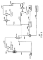
図1は、炭素構造物を、例えば二酸化炭素隔離反応の副成物として発生させる反応システム100のブロック図である。反応システム100には、CO2とCH4との混合物とすることができる供給ガス102が供給される。一部の実施形態においては、反応により、電力プラントなど排気流れからCO2を隔離することができる。他の実施形態において、CH4は、例えば、天然ガス田からのガス流れ中で高濃度にある。供給ガス102中には、C2H6、及びC2H4などのような他の成分が存在する可能性がある。一実施形態において、供給ガス102は、例えば、生成物流れとしての販売に向けて、これらの成分を取り出す処理が施されたものである。
FIG. 1 is a block diagram of a
供給ガス102は、熱交換器104に通され、反応のために加熱される。連続作動中には、加熱の一部分は、反応から回収される熱106を用いて提供される。反応に向けての残りの熱は、以下に説明するように、補助加熱器によって供給することができる。始動中には、補助加熱器は、供給物を適切な反応温度、例えば、約930〜1832°F(約500〜1000℃)にするための全熱を供給するのに使用される。一実施形態において、供給物は、約1650°F(900℃前後)まで加熱される。加熱された供給ガス108は、反応器110に供給される。
The
反応器110内では、ボッシュ反応を用いて、加熱された供給ガス108の一部分と触媒が反応してカーボンナノチューブ112が形成される。以下により詳細に説明するように、反応器110は、例えば、金属ショット及び担持触媒などを含む何種類かの異なる触媒を使用する流動床反応器とすることができる。カーボンナノチューブ112は、反応器110から出るフロー流れ114から分離され、余剰試薬と水蒸気とを含有する廃棄ガス流れ116が残される。フロー流れ114が廃棄ガス流れ116として深冷器に入る前のフロー流れ114からの熱の少なくとも一部分は、加熱された供給ガス108を形成するのに使用される。
In the
廃ガス流れ116は、水120を凝縮させる水深冷器118のような周囲温度熱交換器に通される。得られる乾燥廃ガス流れ122は、ガス分別システム124に対する供給物流れとして使用される。本明細書に使用する場合に、乾燥廃ガス流れは、水の大部分が取り出されているが、依然として少量の水蒸気を有する可能性があることを理解することができる。例えば、乾燥廃ガス流れの露点は、約10℃よりも高く、約20℃よりも高く、又は更に高いとすることができる。露点をガス分別の前に例えば−50℃又はそれ未満まで下げるために乾燥器を使用することができる。
The
ガス分別システム124は、供給ガス102中で低い濃度を有する試薬の一部分を取り出し、この部分を例えば再循環流れ126を供給ガス102と配合することによってプロセスに再循環させる。供給ガス102中の高濃度ガスは、例えば、下流のユーザへの販売により、過剰供給物128として処分することができる。一例として、CO2がCH4との混合気中で高い方の濃度のガスである場合には、廃ガス流れ中に残るCH4を取り出し、それを再循環物126としてプロセス中に戻すためにガス分別システム124を使用することができる。プロセスは、図2に関して更に解説するように、試薬と固体炭素の間の平衡反応として機能する。CH4が過剰である場合には、CO2の殆どを反応において消費することができるので、ガス分別システム124を不要とすることができる。この場合に、CH4を含有し、H2、CO、及び他のガスを含有する可能性がある過剰供給物128は、図1Cに関して解説するように、更に別の精製又はガス分離を用いずに電力プラント内で発電するのに使用することができる。
The
図1Aは、原油増進回収(EOR)プロセスにおける過剰二酸化炭素供給物の使用のブロック図である。過剰供給ガス102(図1)がCO2である場合には、過剰供給物128は、パイプライン130を通じて売り出すために配給業者に販売することができる。パイプライン130からのCO2を個別ユーザが入手して、それを原油増進回収プロセス132に対して使用することができる。例えば、CO2は、炭化水素の回収量を高めるために、炭化水素貯留層を加圧するのに使用することができる。
FIG. 1A is a block diagram of the use of excess carbon dioxide feed in an enhanced oil recovery (EOR) process. If the excess supply gas 102 (FIG. 1) is CO 2 , the
図1Bは、発電プロセスにおける過剰メタン供給物の使用のブロック図である。過剰供給ガス102(図1)がCH4である場合には、過剰供給物128は、その場で又はパイプラインを通じて電力プラント134に過剰供給物128を搬送した後のいずれかで発電するために電力プラント134内に使用することができる。電力プラント134内で発生した電気136は、その場で反応システム100に給電するために使用することができ、又は他の消費者による使用に向けて送電線網に供給することができる。過剰供給物128は、CNT形成プロセスの副成物としてのいくつかの他のガスを含有する可能性があり、従って、パイプライン業者等へのいずれかの商業販売の前に精製することができる。
FIG. 1B is a block diagram of the use of excess methane feed in a power generation process. If the excess supply gas 102 (FIG. 1) is CH 4 , the
図2は、様々な温度条件下で平衡状態にある化学種を示す炭素202と水素204と酸素206の間の平衡のC−H−O平衡状態図200である。様々な平衡を反応として表記したこれら3つの元素が介入する様々な反応が存在する。図を横断している様々な温度での平衡線は、固体炭素が形成されることになる大体の領域を示している。各温度において、固体炭素は、関係する平衡線の上側の領域内では形成されることになるが、平衡線の下側の領域内では形成されないことになる。
FIG. 2 is a C—H—O equilibrium diagram 200 of equilibrium between
炭化水素熱分解は、一般的に酸素又は水が僅かしか存在せず、又は全く存在しない状態で、例えば、高い水素204含有量から高い炭素202含有量までの平衡線208に沿って固体炭素生産に有利に働く水素と炭素の間の平衡反応である。一酸化炭素不均化反応とも呼ばれるブードワ反応は、一般的に酸素又は水が僅かしか存在せず、又は全く存在しない状態で固体炭素生産側に傾き、高い酸素206含有量から高い炭素202含有量までの平衡線208に沿った炭素と酸素の間の平衡反応である。
Hydrocarbon pyrolysis generally produces solid carbon, for example along the
ボッシュ反応は、炭素と酸素と水素とが存在するときに固体炭素生産に有利に働く平衡反応である。C−H−O平衡状態図200では、ボッシュ反応は、三角形の内側領域内、例えば、領域212内に位置し、平衡は、固体炭素と、炭素と水素と酸素とを様々な組合せで含有する試薬との間で確立される。ボッシュ反応領域212内の多くの点が、CNT及び一部の他の形態の固体炭素生成物の形成に有利に働く。反応速度及び生産は、鉄のような触媒の使用によって高めることができる。触媒、反応ガス、及び反応条件の選択は、形成される炭素のタイプの制御を可能にすることができる。従って、これらの方法は、CNTのような固体炭素生成物の生産への新しい道筋を開く。
The Bosch reaction is an equilibrium reaction that favors solid carbon production when carbon, oxygen, and hydrogen are present. In the C—H—O equilibrium diagram 200, the Bosch reaction is located in the inner region of the triangle, eg, in
反応システム
図3は、二酸化炭素とメタンとを含むガス供給物からカーボンナノチューブを製造するための一反応器システム300の単純化したプロセスフロー図である。図示のように、一反応器システム300は、CO2が多い又はCH4が多い供給ガス302に対して使用することができる。より多いCO2含有量の供給ガスに対するより具体的な反応器システムを図5及び図6に関して解説し、より多いCH4含有量の供給ガスに対するものを図7及び図8に関して解説する。反応システム300では、供給ガス302は、少ないガスの濃度が高められた再循環ガス304と組み合わされる。この組合せは、静止混合器306を用いて行うことができる。
Reaction System FIG. 3 is a simplified process flow diagram of one
組合せガス流れ308は、反応器流出物流れによって加熱するために、単一の熱交換器310又は熱交換器310の組に通される。温度は、加熱されたガス流れ312に向けて90°F(約32.2℃)から約1400°F(約760℃)まで上げることができる。この温度は、連続作動中に反応を維持するのに十分とすることができる。しかし、熱の一部は、始動中に反応物をこの温度に到達させるために熱を加える上で特に有利とすることができるパッケージ加熱器314によって供給することができる。次に、高温ガス流れ16が、流動床反応器318内に導入される。実施形態に対して使用することができる一般的な流動床反応器に対しては、図9に関して解説する。流動床反応器318内では、カーボンナノチューブが触媒粒子上に形成される。触媒粒子及び反応に対しては、図10に関してより詳しく解説する。
The combined
カーボンナノチューブは、第1の流動床反応器318から反応器流出物流れ320中に運ばれる。反応器流出物流れ320は、約1650°F(約900℃)の温度にあるとすることができ、組合せガス流れ308と熱を交換するのに、例えば、反応物を加熱するのに使用される熱の一部又は全てを与えることによって冷却することができる。冷却の前又は後のいずれかにおいて、反応器流出物流れ320は、カーボンナノチューブ324を取り出すために、サイクロン分離器のような分離デバイス322に通される。得られる廃ガス流れ326は、熱交換器310内で組合せガス流れ308に熱を与えるために使用することができる。炭素は、廃ガス流れ326よりも低い温度にある2次分離デバイス(図示せず)内で取り出すことができる。
Carbon nanotubes are conveyed from the first
組合せガス流れ308に熱を与えた後の冷却された廃棄物流れ328は、周囲温度熱交換器330に通され、次に、分離容器332に供給される。水334は、分離容器332内に沈降し、底部から取り出される。得られるガス流れ336は、100°F(約38℃)前後で、約540psia(約3,720kPa)の圧力にある。一実施形態において、ガスは、次に、乾燥器(図示せず)内で低露点まで乾燥させる。この流れはコンプレッサ338に入り、コンプレッサ338は、ガス流れ336の圧力を約1050psia(約7,240kPa)まで高めて高圧流れ340を形成し、この高圧流れ340は、別の周囲温度熱交換器342に通される。例えば、乾燥器が使用されなかった場合には、周囲温度熱交換器342からの高圧流れ340は、あらゆる残留水334の除去のために分離容器344に供給される。
The cooled
供給ガス302中でCO2が過剰である場合には、乾燥されたガス流れ346は、次に、ガス分別システム348に送られ、ガス分別システム348は、再循環ガス304から過剰供給物350を分離する。相応のCO2過剰に基づく反応システム300では、過剰供給物350は主にCO2を含むことができ、再循環ガス304は主にCH4を含むことができる。相応のCH4過剰に基づく反応システム300では、過剰供給物350は実質的なCO2含有量を含むことにはならず、一部分を更に別の精製なしに再循環させることができる。一部の実施形態において、プラント内での使用に向けて燃料ガス流れ、洗浄ガス流れ、又はこれらの両方を供給するために、過剰供給物350の一部分、再循環ガス304、又はこれらの両方を利用することができる。
If there is an excess of CO 2 in the
使用される反応条件は、ステンレス鋼ビーズを含むことができる触媒自体の選択に示すように、金属面の有意な劣化をもたらす可能性がある。それに応じて、プロセスは、その後の図に関してより詳しく解説するように、プロセス条件に露出される金属の量を低減するように設計することができる。 The reaction conditions used can result in significant degradation of the metal surface, as shown in the selection of the catalyst itself that can include stainless steel beads. Accordingly, the process can be designed to reduce the amount of metal exposed to process conditions, as will be discussed in more detail with respect to subsequent figures.
図4は、二酸化炭素とメタンとを含むガス供給物からカーボンナノチューブを製造するための二反応器システム400の単純化したプロセスフロー図である。類似の番号が振られた項目は、図3に関して解説したものと同様である。二反応器システム400では、得られる廃ガス流れ402は、熱交換器404内に熱を供給するのに使用される。炭素は、2次分離デバイス(図示せず)において、廃ガス流れ402よりも低い温度で取り出すことができる。この除去は、次の順番の反応器への供給ガスを加熱すると同時に廃ガス流れ402を冷却するために、複数の並列熱交換器を使用することができる場合に特に容易である。通常、廃ガス流れ402中に存在する水蒸気のうちのいずれかの凝縮の前に、炭素固体の全てが分離デバイスによって取り出されることになる。
FIG. 4 is a simplified process flow diagram of a two-
次に、冷却された廃ガス流れ406は、周囲温度熱交換器408に通され、周囲温度熱交換器408は、冷却された廃ガス流れ406を更に冷却し、その結果、水の大部分が凝縮して液体として形成され、次に、分離容器410に供給される。水334が分離容器から取り出され、反応物流れ412が、約100°F(約38℃)で分離容器の上部から抜け出る。
The cooled
反応物流れ412は、熱交換器404を通過し、廃ガス流れ402からの廃熱によって加熱される。加熱された流れ414は第2の流動床反応器416に供給され、その内部で付加的なカーボンナノチューブが形成される。しかし、加熱された流れ414は、第2の流動床反応器416内でカーボンナノチューブを形成するには十分に高い温度になく、例えば、約1600°F(約871℃)よりも高くない可能性がある。加熱された流れ414の温度を高めるために、第2のパッケージ加熱器418を使用することができる。第2のパッケージ加熱器418は、第1のパッケージ加熱器314内の別個の加熱域とすることができる。一部の実施形態において、第2の反応器流出物流れ420は、加熱された流れ414に熱を与えるために使用される。第2の反応器流出物流れ420は、次に、第2の反応器流出物流れ420から炭素生成物を分離するために、サイクロン分離器のような第2の分離器422に供給される。得られる廃ガス流れ424は、熱交換器310を通過するときに組合せガス流れ308に熱を与えるために使用される。
Reactant stream 412 passes through
この実施形態では2つの流動床反応器318及び416しか示していないが、反応システム400は、必要に応じてより多くの反応器を含むことができる。反応器の個数の決定は、供給原料の濃度と、各供給原料の望ましい残留量とに基づくとすることができる。いくつかの状況では、3つ、4つ、又はそれよりも多い反応器を順番に使用することができ、この場合に、各反応器からの流出物流れは、次の順番の反応器に対する供給ガスに熱を与える。更に、実施形態において他の構成を使用することができるので、反応器は、流動床反応器である必要はない。例えば、固定床反応器、管状反応器、連続供給反応器、又は幾つもの他の構成を使用することができる。上述したように、CH4が過剰状態の実施形態において、ガス分別システム348は、乾燥ガス流れ346を過剰供給物350と再循環ガス304とに分割することができるマニホルドで置換することができる。
Although only two
図5は、二酸化炭素が過剰状態にある場合の二酸化炭素とメタンとを含むガス供給物からカーボンナノチューブを製造するための一反応器システム500の単純化したプロセスフロー図である。図5では、類似の番号の項目は、図3に関して記載したものと同様である。プロセス内で番号が振られた菱形は、高いCO2含有量の供給ガス302に対して表1に提供しているプロセスシミュレーション値に対応する。図3の場合のように、供給ガス302は、静止混合器306に通され、その内部で、メタンが多い再循環ガス304と組み合わされる。組合せガス流れ308は、例えば、多管式熱交換器502を含む熱交換器310に通される。図5のより詳細なプロセスフロー図と図3のものとの主な相違点は、反応器流出物流れ320からCNTを分離する前に反応器流出物流れ320を冷却するための熱交換器の使用である。
FIG. 5 is a simplified process flow diagram of one
この実施形態において、加熱されたガス流れ312は、第2の熱交換器504を貫流する前に、熱交換器310内で約800°F(約427℃)の温度まで上げられる。第2の熱交換器504内では、加熱されたガス流れ312は、矢印508に示すように、第1のセラミックブロック熱交換器506を貫流する。第1のセラミックブロック熱交換器506内に累積された熱は、加熱されたガス流れ312に交換され、その温度を約1540°F(838℃)まで高めることができる。
In this embodiment, the
第1のセラミックブロック熱交換器506を用いて加熱されたガス流れ312が加熱されるのに対して、第2のセラミックブロック加熱器510を用いて、この流れに、矢印512に示すように第2のセラミックブロック加熱器510を貫流させることにより、反応器流出物流れ320が冷却される。第2のセラミックブロック熱交換器510が、選択された温度に達するか、又は第1のセラミックブロック熱交換器506が、選択された温度まで下がると、注入弁514及び排出弁516の位置が変更される。言い換えれば、開いた弁が閉じられ、閉じた弁が開かれる。導入弁の位置の変更は、いずれのセラミックブロック熱交換器506又は510が反応器318からのフローによって加熱され、いずれのセラミックブロック熱交換器506又は510が、加熱されたガス流れ312を加熱するのに使用されるかを変更する。
The
熱は、反応に向けて温度を十分に高めるには十分ではない可能性がある。従って、図3に関して上述したように、加熱されたガス流れ312の温度を更に上げて、流動床反応器318に供給することができる高温ガス流れ316を形成するために、パッケージ加熱器314を使用することができる。CNTは、流動床反応器318内で形成され、反応器流出物流れ320中に運び出される。
The heat may not be sufficient to raise the temperature sufficiently for the reaction. Thus, as described above with respect to FIG. 3, the
(表1)

第2のセラミックブロック加熱器510を貫流した後に、反応器流出物320は、そこからCNTを取り出すために使用される分離システム518に流される。この実施形態において、CNTの分離システム518は、サイクロン分離器520、ロックホッパー522、及びフィルタ524を含む。CNTのうちの大部分がサイクロン分離器520によって取り出され、ロックホッパー522内に堆積した後に、フィルタ524を用いて廃ガス流れ526から残留CNTが取り出される。それによって廃ガス流れ526内の残存CNTによってもたらされる閉塞又は他の問題を防ぐのを助けることができる。フィルタ524は、タイプの中でも取りわけ、バッグフィルタ、焼結金属フィルタ、及びセラミックフィルタを含むことができる。CNT分離システム518からのCNTは、図10に関してより詳細に解説するパッケージ化システムに誘導することができる。フィルタ524の後に、廃ガス流れ526は熱交換器310を貫流し、その後に周囲温度熱交換器330に流れ、更に水の分離に向けて分離容器332に供給される。分離容器32を貫流した後のフローは、図3に関して記載したものと同様である。
After flowing through the second
この実施形態において、2つの付加的な流れをガス分別システムから出る分離された流れから供給することができる。再循環ガス304からは、燃料ガス流れ528を採取して、電力プラント134(図1)のような電力プラントに送ることができる。CO2排出流れからは、フィルタ524又はサイクロン520のような機器の様々な部品を洗浄するために使用することができる洗浄ガス流れ530を採取することができる。
In this embodiment, two additional streams can be supplied from the separated streams exiting the gas fractionation system. From
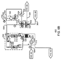
図6A、図6B、及び図6Cは、二酸化炭素が過剰状態にある二酸化炭素とメタンとを含むガス供給物からカーボンナノチューブを製造するための二反応器システム600の単純化したプロセスフロー図である。類似の番号が振られた項目は、図3及び図5に関して記載したものである。図5に図示の実施形態と図6A〜図6Cに示すものとの間の主な相違点は、第1の反応器からの流出物内の残留反応物から別の量のCNTを形成する第2の反応器の使用である。
6A, 6B, and 6C are simplified process flow diagrams of a
一反応器システム500(図5)に関して上述したように、フローは、供給ガス302が、静止混合器304内で再循環ガス304と混合される時に始まる。組み合わされたガス流れ308には、反応器流出物からの高温廃ガス流れによって加熱するために、熱交換器602を貫流させる。熱交換器602は、図5の熱交換器310に対して記載したものと類似のものとすることができる。熱交換器602からの加熱されたガス流れ312は、図5の第2の熱交換器504に対して上述したように、加熱されたガス流れ312を更に加熱するために、セラミックブロック熱交換器506及び510を使用することができる第2の熱交換器604を通過する。得られる高い温度の加熱されたガス流れ312は、高温ガス流れ316を形成するためにパッケージ加熱器内で更に加熱することができ、高温ガス流れ316は、流動床反応器318に供給することができる。流動床反応器318内ではCNTが形成され、反応器流出物流れ320中に運び出される。
As described above with respect to one reactor system 500 (FIG. 5), flow begins when
反応器流出物流れ320は、熱交換器606内に流すことができ、その内部のセラミックブロック熱交換器510内で、フローは矢印512に示すように冷却される。熱交換器606からの冷却された流出物流れ607は、分離システム608に流すことができ、その内部の例えば図5に関して記載したサイクロン分離器520内で、冷却された流出物流れ607からCNTが分離される。得られる廃ガス流れ609は、残留CNTのうちの大部分を取り出すために、分離システム608内のフィルタ524を貫流させることができる。フィルタ524の後に、廃ガス流れ609は熱交換器610を貫流させられ、その後に、周囲温度熱交換器612、更に水の分離に向けて分離容器614に流れる。得られる乾燥した流れ616は、廃ガス流れ609と熱を交換することによって加熱するために、次に、熱交換器610を貫流させることができる。熱交換器610は、この場合に、乾燥流れ616の温度を点11における約100°F(約37.8℃)から点12における約715°F(約379.4℃)まで増大させる多管式熱交換器422を含むことができる。加熱されたガス流れ618は、第2の熱交換器606内のセラミックブロック加熱器506の中を流れることによって更に加熱される。
更に別の熱量を与えて加熱されたガス流れ618を反応に十分な温度にするために、パッケージ加熱器622を使用することができる。最終的な高温ガス流れ624は、別の分量のCNTを形成する第2の流動床反応器626に供給される。
A
CNTは、第2の流動床反応器626から反応器流出物流れ628の中に運び出され、反応器流出物流れ628は、冷却のために第2のセラミックブロック熱交換器510を貫流させられる。第2のセラミックブロック熱交換器510からの流出物流れ630は、分離システム608に対して上述したように、分離システム632に流される。分離システム632内のフィルタ524が廃ガス流れ634からCNTを取り出した後に、第2ガス流れ634は、更に別の冷却に向けて熱交換器602に通される。得られる廃ガス流れ526は、水を凝縮させるために、周囲温度熱交換器330に渡される。
CNTs are carried from the second
第2の熱交換器606内のセラミックブロック熱交換器506は、図5の第2の熱交換器504に関して解説したように、熱交換されたフローを有するように構成される。システム600の他の部分は、プロセス値は異なる場合があるが、図3及び図5に関して記載したものと同様である。このシステムに関するプロセス値を二反応器システムのシミュレーションに関する表2又は表3に示している。更に、実施形態において2つよりも多い反応器のシステムを使用することができる。
The ceramic
従来の図に関して解説したように、第3の分離容器344内での高圧流れ340からの最後の分量の水の除去の後の乾燥ガス流れ346は、CO2廃棄物流れ350から高メタン再循環ガス304を取り出すことができるガス分別システム348に送られる。ガス分別システム348に対しては、図11に関してより詳しく解説する。
The
(表2)
(表3)
プロセスに他のガスを供給するために、個々の流れ304及び350を使用することができる。例えば、システム600又は送電線網に電力を供給するために、高メタン再循環ガス304から燃料ガス流れ528を取り出して、タービン、ボイラー、又は他の機器を作動させるのに使用することができる。更に、CO2廃棄物流れ350から洗浄ガス流れ530を取り出すことができる。洗浄ガス流れ530は、図12に関して説明するように、CNTを冷却して洗浄するために使用することができる。洗浄ガスは、フローが逆行した時にセラミック熱交換器506又は510の残存CNTを吹き払うことのようなプラント内の様々な洗浄機能に対して使用することができる。
表2及び表3に示すプロセス条件は、シミュレーションによって決定されたプラント内で見られる可能性がある条件の例であるように意図したものでしかない。実際の条件は大きく異なる場合があり、図示した条件とは大きく異なる可能性がある。図7及び図8に関して解説するように、高メタン供給ガスに対して類似のプラント構成を使用することができる。更に、再循環流れ及び流出廃棄物流れは、実質的な量の水素及び一酸化炭素、例えば、約5mol%、10mol%、又は20mol%よりも多い各成分を含有することができる。これらの成分は、一般的に供給物流れ及び全ての非CO2生成物流れ中に存在することになり、すなわち、再循環メタンは、常にある程度のCO及びH2を含有することになる。 The process conditions shown in Tables 2 and 3 are only intended to be examples of conditions that may be found within a plant determined by simulation. Actual conditions may differ significantly and may differ significantly from the illustrated conditions. Similar plant configurations can be used for high methane feed gas, as will be discussed with respect to FIGS. In addition, the recycle stream and the effluent waste stream can contain substantial amounts of hydrogen and carbon monoxide, for example, greater than about 5 mol%, 10 mol%, or 20 mol% of each component. These components will generally be present in the feed stream and all non-CO 2 product streams, ie, recycle methane will always contain some CO and H 2 .
図7は、メタンが過剰状態にある二酸化炭素とメタンとを含むガス供給物からカーボンナノチューブを製造するための一反応器システム700の単純化したプロセスフロー図である。類似の番号が振られた項目は、従来の図で解説したものと同様であり、図を簡略化するために、参照番号の一部分を割愛した。この実施形態において、供給ガスは、二酸化炭素よりもメタンが多いものとし、例えば、80mol%前後のCH4と20mol%前後のCO2とにおけるものとすることができるが、あらゆる比を使用することもできる。高メタン供給ガス702は、CNTを形成するのに一反応器システム700又は二反応器システム800(図8)に使用することができる。これらのシステム700及び800は、ガス分別システム348が、マニホルド704で置換されていることを除いて、上記に解説したものと同様である。ガス供給物702はメタンが多く、CO2は、プロセス内でほぼ使い尽くすことができる。それに応じて、更に別の分離の必要をなくすことができる。
FIG. 7 is a simplified process flow diagram of one
マニホルド704内では、乾燥ガス流れ346を複数の部分に分離することができる。第1の部分は、静止混合器306内で供給ガス702と混合され、反応器に供給物を与えるための組合せガス流れ308を形成する再循環ガス706を形成する。第2の部分は、例えば、この施設に位置付けられた電力プラント134に供給物を与える低BTU燃料ガス528として使用することができる。乾燥ガス流れ346は、少量のCO2に加えて、類似の分量のCH4、CO、及びH2を含むので、パイプラインに販売することができる前にある程度の精製を必要とすることになる。従って、外部に搬送されるCH4混合物の流れ708は、消費者用途に使用されるもの以外の電力プラントに限定されることになる。
Within the manifold 704, the
図8A、図8B、及び図8Cは、メタンが過剰状態にある二酸化炭素とメタンとを含むガス供給物からカーボンナノチューブを製造するための二反応器システムの単純化したプロセスフロー図である。類似の番号が振られた項目は、従来の図において解説したものと同様であり、図を簡略化するために、一部の参照番号を割愛した。 8A, 8B, and 8C are simplified process flow diagrams of a two-reactor system for producing carbon nanotubes from a gas feed comprising carbon dioxide and methane in excess of methane. Items assigned with similar numbers are the same as those explained in the conventional drawings, and some reference numbers are omitted to simplify the drawings.
ガス供給物702はメタンが多いので、乾燥ガス流れ346は、低CO2含有量を有することになり、分離を不経済にする。従って、図7において上述したように、ガス分別システムをマニホルド704で置換することができる。プロセスの残りの部分は、図5に関して解説したシステム500と同じになる。しかし、CH4混合物708は、エネルギ市場に商業販売される可能性があるので、より高い純度のCH4、例えば、約99mol%又はそれよりも多いCH4を発生させるように構成された精製システムを使用することができる。
Since the
カーボンナノチューブの形成のためのシステムは、図示の流動床反応器を含む幾つものタイプの幾つもの反応器を含むことができることを理解することができる。一実施形態において、カーボンナノチューブを形成するのに、2つよりも多い反応器を使用することができる。 It can be appreciated that a system for the formation of carbon nanotubes can include several reactors of several types, including the illustrated fluidized bed reactor. In one embodiment, more than two reactors can be used to form carbon nanotubes.
反応器システム Reactor system
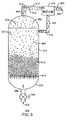
図9は、カーボンナノチューブ902を形成するための流動床反応器900の図面である。高温ガス供給物流れ904は、ライン906を通じて流動床反応器900の底部に供給される。反応器内への高温ガス供給物流れ904のフローを調整するために制御弁908を使用することができる。高温ガス供給物流れ904は、分配器板910を貫流し、反応器壁914によって固定された触媒ビーズ912の床を流動化することになる。本明細書に使用する「流動化」は、触媒ビーズ912が互いにばらばらに流動することになり、それによってその間をガスの気泡が通過し、液状の流動挙動を与えることを意味する。本明細書に解説するように、金属面は、この反応のための触媒として機能することになるので、反応条件は、あらゆる露出金属面に対して非常に過酷なものである。従って、反応は、露出金属面の緩慢な劣化をもたらすことになる。それに応じて面を保護するために、反応器壁914及びヘッド915を含む反応器の内面に加えて分配器板910、並びに他の部分をセラミック材料で製作することができる。
FIG. 9 is a drawing of a
高温ガス供給物流れ904が、触媒粒子の流動床912を貫流するときに、触媒ビーズ912からCNT902が形成されることになる。流れている高温ガス供給物流れ904は、CNT902をオーバーヘッドライン916内に運び入れ、その内部で反応器900から取り出される。例えば、制御弁908によって調節される流量に基づいて、一部の量の触媒ビーズ912又は触媒ビーズ912から分解した粒子が、オーバーヘッドライン916内に運び入れられる可能性がある。従って、反応器流出物流れ920から触媒ビーズ912及び大きい粒子を分離し、それらを再循環ライン922を通じて反応器900に戻すために触媒分離器918を使用することができる。触媒分離器918において、サイクロン分離器、沈降タンク、及びホッパーなどのような幾つもの構成を使用することができる。流動床において発生する反応を図10でより詳細に解説する。
As hot
図10は、触媒ビーズ1002上でのカーボンナノチューブの形成における触媒反応1000の概略図である。高温ガス供給物流れ中のCH4の一部分とCO2の一部分の間の初期反応1004は、化学量論的な量のCO及びH2の形成をもたらす。過剰な量の供給源ガス1006が反応器を貫流し続け、床を流動化するのを促進し、CNT1008及び触媒粒子1010を運び去る。
FIG. 10 is a schematic diagram of a
CNT1008を形成する反応は、触媒ビーズ1002上で発生する。CNT1008のサイズと、単壁又は多壁のCNT1008のようなCNT1008のタイプとを粒1012のサイズによって制御することができる。言い換えれば、粒界における十分なサイズの鉄原子の核は、触媒ビーズ1002上での炭素生成物の成長における核形成点を形成する。一般的に小さい粒1012は、CNT1008内で少ない層をもたらすことになり、単壁CNT1008を取得するために使用することができる。最終生成物の形態に影響を及ぼす上で、反応温度、圧力、及び供給ガス流量を含む他のパラメータを使用することができる。
The reaction to form
COとH2は、粒界1014において反応し、活性触媒粒子1016を触媒ビーズ1002から浮き剥がし、H2O1018とCNT1008の固体炭素とを形成する。CNT1008は、触媒ビーズ1002及び触媒粒子1010から離脱する。大きい触媒粒子1010は、例えば、図9に関して解説した触媒分離器918によって捕捉して反応器に戻すことができ、それに対して非常に微細な触媒粒子1010は、CNT1008と共に運び出されることになる。最終生成物は、約95mol%の固体炭素と約5mol%の鉄のような金属とを含むことになる。多くの場合にCNT1008は凝集して、最終生成物の一般的な形態である集塊1020を形成することになる。一部の量のCO及びH2は、反応することなく反応器を通過し、反応器流出物流れ中の汚染物質である。
CO and H 2 react at the
反応が進む時に、触媒ビーズ1002は劣化し、最終的に使い尽くされる。従って、この反応をメタルダスティング反応として説明することができる。一部の実施形態において、反応条件と接触状態にある金属面は、劣化することになるだけではなく、低品質の生成物の形成をもたらす可能性もあるので、セラミック裏打ちによる侵食から保護される。
As the reaction proceeds, the
触媒ビーズ1002は、ニッケル、ルテニウム、コバルト、モリブデン、及び他のもののような幾つもの他の金属を含むことができる。しかし、触媒ビーズ1002上の触媒箇所は、主に鉄原子から構成される。一実施形態において、触媒ビーズ1002は、金属ショット、例えば、ショットブラストに使用される約25〜50メッシュの金属ビーズを含む。一実施形態において、触媒は、ステンレスボールベアリングなどとすることができる。
The
ガス分別システム Gas separation system
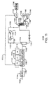
図11は、カーボンナノチューブの生産のために反応器システム内に使用することができるガス分別システム1100の単純化したプロセスフロー図である。ガス分別システム1100は、図4に関して解説したもののような高CO2反応器システムと共に使用することができる。ガス分別システム1100では、露点を約−70°F(約−56.7℃)又はそれ未満まで低下させるために、供給ガス1102は乾燥器1104に供給される。供給ガス1102は、図3〜図5に関して解説した乾燥ガス流れ366に対応することができる。乾燥器1104は、分子篩、乾燥剤などのような吸着剤を含有する固定乾燥器床又は流動乾燥器床とすることができる。低温乾燥器システムのような他の乾燥器技術を使用することができる。一部の実施形態において、乾燥器は、コンプレッサ358の前に設置することができ、それによって周囲温度熱交換器362の必要性を排除することができる。
FIG. 11 is a simplified process flow diagram of a
次に、乾燥ガス供給物1106は、分離のために温度を低下させるために低温深冷器1108を通過して供給される。CO2は、約−77°F(約−61℃)でガスから凝縮することになるので、温度をこのレベル前後まで低下させるのに多段深冷システム1110を使用することができる。多段深冷システム1110は、排気ガスを乾燥供給ガス1106からのエネルギ1113で加熱するのに使用される熱回収システム1112を含むことができる。
The
深冷供給物1116は、液体流れ1120と蒸気流れ1122とに分離するための分離容器1118に供給される。蒸気流れ1122は、断熱膨張プロセスにおいて機械的仕事1126を発生させることによって温度を下げるために膨張器1124に通される。一実施形態において、機械的仕事1126は、プラント内に使用される電気の一部分を供給することができる発電器1128を駆動するのに使用される。別の実施形態において、機械的仕事1126は、例えば、多段深冷システム1110のための冷却剤流れを圧縮するためのコンプレッサを駆動するのに使用される。膨張は、2相流れ1130をもたらすことができる。
液体流れ1120及び2相流れ1130は、分離カラム1132にそれに沿った異なる点で供給される。分離カラム1132には再沸器1134によって熱が供給される。再沸器1132は、熱交換器1136からの流れによって加熱される。熱交換器1136は、周囲温度よりも小さいが、分離カラム1132よりも温かい深冷器システムの一部とすることができる。カラム底流れ1138は再沸器1134に通され、一部分1140は、温められた後に再注入される。再沸器1134からの排出流れ1142は、CO2生成物1144を与える。CO2生成物1144の一部分1146は、エネルギを再沸器1134に運ぶために熱交換器1136を通過して再循環させることができる。
分離カラム1132からのオーバーヘッド流れ1148は、例えば、約73mol%のCH4と約23mol%のCO2とを含むメタンが増加した流れである。上述したように、オーバーヘッド流れ1148は、乾燥ガス供給物1106を冷却するために深冷器システム1112内に使用することができ、オーバーヘッド流れ1148は温められて再循環ガス1150を形成する。再循環ガス1150中には、例えば、約3.5mol%のCO及びH2を含む他の成分が存在する可能性がある。メタンが、図9に関して解説した高メタン反応システムにおけるもののような販売が考えられる場合には、図9に関して解説した高純度分離システムを使用することができる。
図11に関して解説した構成及びユニットは例示的なものに過ぎない。これらのシステムには幾つもの変更を加えることができる。更に、実施形態において、流量及び純度レベルに到達できる限り、他のガス分離システムを使用することができる。 The configurations and units described with respect to FIG. 11 are merely exemplary. A number of changes can be made to these systems. Furthermore, in embodiments, other gas separation systems can be used as long as flow and purity levels can be reached.
パッケージ化システム Packaging system
図12は、一反応器システムからの流出物流れから分離されたカーボンナノチューブをパッケージ化することができるパッケージ化システム1200の単純化したプロセスフロー図である。パッケージ化システム1200は、図5及び図6に示す分離システム518及び632のロックホッパー522に重なり、パッケージ化に向けてプロセスからCNTを単離するのに使用される。
FIG. 12 is a simplified process flow diagram of a packaging system 1200 that can package carbon nanotubes separated from an effluent stream from one reactor system. The packaging system 1200 overlies the
パッケージ化システム1200は、パッケージ化トレーン1202の一部である。パッケージ化トレーン1202は、CNTをロックホッパー522からCNTを取り出すためのサンプリング弁1204を有することができる。サンプリング弁1204は、回転サイクルの一部分中にある量のCNT及びガスが通ることを許すように構成された回転弁とすることができる。一部の実施形態において、サンプリング弁1204は、選択された期間の間に完全に開き、完全に閉じる前に、選択された量のCNT及びガスが通ることを許すように構成されたボール弁とすることができる。CNT及びガスは、洗浄及び冷却に向けてドラム1206内に流れ込むことが許される。
The packaging system 1200 is part of the
サンプリング弁1204が閉じた後に、CO、H2、H2O、及びCH4のような残留ガスを掃き出すために、洗浄流れ1208をドラム1206内に開くことができる。上述したように、洗浄流れ1208は、ガス分別システムのCO2濃縮側から、例えば、図5に関して解説した洗浄ガス流れ530として採取することができる。洗浄排出流れ1210は、一部の量のCNT及び他の微粒子を運ぶことになり、洗浄帰還物1214としてプロセスに送り返される前にフィルタ1212に通すことができる。フィルタ1212は、バッグフィルタ、サイクロン分離器、又はあらゆる他の適切な分離システムとすることができる。洗浄が完了した後に、パッケージ化弁1216が開くことになり、CNTを含む流れ1218を充填ステーション1220に流して、販売に向けてドラム又はタンク内にパッケージ化することが可能になる。
After the
図13は、二反応器システムにおいて各反応器流出物流れから分離されたカーボンナノチューブをパッケージ化することができる分離システム1300の単純化したプロセスフロー図である。図13に示すように、図7及び図8に関して解説したもののような二反応器システムでは、システム内の各反応器は、パッケージ化トレーン1202及び1302のような別個のパッケージ化トレーンを有することができる。第1のパッケージ化トレーン1202は、分離システム518のロックホッパー522に結合することができ、それに対して第2のパッケージ化トレーン1302は、分離システム632のロックホッパー522に結合することができる。異なる反応器は、異なる量のCNTを生産している可能性があるので、機能は同じとすることができるが、機器は、異なるサイズにすることができる。例えば、第1のシミュレーションでは、第1のパッケージ化トレーン1202によって単離されるCNTの量は、約162.7トン/日(148,000kg/日)である場合があり、それに対して第2のパッケージ化トレーン1302に取り出される量は、約57.5トン/日(52,000kg/日)である可能性がある。
FIG. 13 is a simplified process flow diagram of a
上述の単離システムは例示的なものに過ぎない。実施形態において幾つもの他のシステムを使用することができる。しかし、CNTは、形態的分布に依存して約0.5g/ccよりも低い超低密度を有し、かつプラント環境に失われる量を低減するためにこれらのCNTを雰囲気から単離するように構成されたシステム内で最適にパッケージ化することができる。更に、洗浄ガスは、図5及び図6のシステムにおいて示すように、供給ガスから単離することができ、又は例えば図7及び図8のシステムにおいて示すように別個に供給することができる。 The isolation system described above is exemplary only. A number of other systems can be used in embodiments. However, CNTs have an ultra-low density of less than about 0.5 g / cc, depending on the morphological distribution, and seem to isolate these CNTs from the atmosphere to reduce the amount lost to the plant environment. It can be optimally packaged in a system configured as described above. Further, the cleaning gas can be isolated from the feed gas, as shown in the systems of FIGS. 5 and 6, or can be supplied separately, for example, as shown in the systems of FIGS.
方法
図14は、メタンと二酸化炭素とを含む供給ガスからカーボンナノチューブを発生させる方法1400である。方法1400は、CO2/CH4混合供給原料が得られるブロック1402で始まる。供給原料は、幾つもの供給源から取得することができる。上述したように、供給原料は、地下貯留層から採取された天然ガス、発電プラントからの排気ガス、又は天然供給源又はプラント供給源からの幾つもの他のガスを含むことができる。更に、実施形態において、シンガス、CO、H2、他の炭化水素などのような他の材料を含む他の供給原料を使用することができる。
Method FIG. 14 is a
ブロック1404において、供給原料は、プロセス内で発生した廃ガスから得られた再循環ガスと組み合わされる。本明細書に記述するように、再循環ガスは、低温ガス分別、並びに幾つもの他の技術によって廃ガスから取得することができる。ブロック1406において、組合せガス流れは、反応プロセスから回収された廃熱を用いて加熱される。加熱後に、ブロック1408において、組合せガス流れは、反応器内で金属触媒と反応し、CNTが形成される。ブロック1410において、CNTは、廃ガスから分離される。ブロック1412において、分離されたCNTは、洗浄され、冷却され、更にパッケージ化されて市場に送られる。
At
廃ガスは、反応中に形成された過剰水を取り出すために冷却される。プロセスは、高温高圧に実施されるので、周囲温度熱交換器は、水蒸気を凝縮させるほど十分な冷却を与える。ブロック1406〜1414において記載したプロセスは、反応システム内の各順番の反応器において繰り返されることになる。 The waste gas is cooled to remove excess water formed during the reaction. Since the process is performed at high temperature and pressure, the ambient temperature heat exchanger provides sufficient cooling to condense the water vapor. The process described in blocks 1406-1414 will be repeated in each sequential reactor in the reaction system.
ブロック1416において、廃ガスは、CO2濃縮流れとCH4濃縮流れとに分別される。ブロック1418において、過剰試薬を含有するいずれかの試薬は販売することができ、それに対して他方の流れは、プロセス内に使用するためにブロック1404に再循環させることができる。
At
特許請求する主題の更に他の実施形態は、以下に番号が振られた項に列記する要素のあらゆる組合せを含むことができる。 Still other embodiments of the claimed subject matter can include any combination of the elements listed in the following numbered sections.
第1項.カーボンナノチューブの生産のためのシステムであって、廃ガス流れからの廃熱を用いて供給ガスを加熱するように構成された供給ガス加熱器と、ボッシュ反応において供給ガスからカーボンナノチューブを形成するように構成された反応器と、廃ガス流れを形成する反応器流出物流れからカーボンナノチューブを分離するように構成された分離器と、周囲温度熱交換器と、廃ガス流れから水の大部分を分離して乾燥廃ガス流れを形成するように構成された分離器とを含む水除去システムとを含むシステム。 Item 1. A system for the production of carbon nanotubes, comprising a feed gas heater configured to heat feed gas using waste heat from a waste gas stream, and forming carbon nanotubes from the feed gas in a Bosch reaction A reactor configured to separate carbon nanotubes from a reactor effluent stream forming a waste gas stream, an ambient temperature heat exchanger, and a majority of water from the waste gas stream. A water removal system comprising a separator configured to separate to form a dry waste gas stream.
第2項.周囲温度熱交換器が水深冷器を含む第1項に記載のシステム。 Section 2. The system of claim 1 wherein the ambient temperature heat exchanger comprises a water chiller.
第3項.周囲温度熱交換器が空冷熱交換器を含む第1項又は第2項に記載のシステム。
第4項.システムの初期始動において供給ガスを加熱するように構成されたパッケージ加熱器を含む第1項、第2項、又は第3項に記載のシステム。
Item 4. 4. The system of
第5項.乾燥廃ガス流れの圧力を増大するように構成されたコンプレッサと、乾燥廃ガス流れから水を取り出すように構成された最終水除去システムとを含む第1項から第4項のいずれか1項に記載のシステム。 Item 5. 5. Any one of paragraphs 1 to 4 including a compressor configured to increase the pressure of the dry waste gas stream and a final water removal system configured to remove water from the dry waste gas stream. The system described.
第6項.乾燥廃ガス流れからメタン豊富流れとCO2豊富流れとを分離するように構成されたガス分別システムを含む第5項に記載のシステム。 Item 6. The system of claim 5 including a gas fractionation system configured to separate a methane rich stream and a CO 2 rich stream from the dry waste gas stream.
第7項.供給ガス加熱器の前にメタン豊富流れを供給ガス内に混合するように構成された混合システムを含む第6項に記載のシステム。 Item 7. The system of claim 6 including a mixing system configured to mix the methane rich stream into the feed gas prior to the feed gas heater.
第8項.反応器が、供給ガスの向流流れを用いて触媒を流動化する流動床反応器である第1項から第5項のいずれか1項に記載のシステム。 Item 8. 6. The system of any one of paragraphs 1-5, wherein the reactor is a fluidized bed reactor that fluidizes the catalyst using a countercurrent flow of feed gas.
第9項.触媒が、金属ショットブラストビーズを含む第8項に記載のシステム。 Item 9. The system of claim 8 wherein the catalyst comprises metal shot blast beads.
第10項.乾燥廃ガス流れを廃ガス流れからの廃熱を用いて加熱して第2の供給ガスを形成するように構成された熱交換器と、第2の供給ガスからカーボンナノチューブを形成するように構成された第2の反応器と、第2の反応器からの流出物流れからカーボンナノチューブを分離して第2の廃ガス流れを形成するように構成され、供給ガス加熱器内に使用される廃ガス流れが第2の廃ガス流れを含む分離器と、周囲温度熱交換器を用いて第2の廃ガス流れを深冷して第2の廃ガス流れから水を分離し、水の大部分を取り出して第2の乾燥廃ガス流れを形成するように構成された水除去システムとを含む第1項から第5項、又は第8項のうちのいずれか1項に記載のシステム。 Item 10. A heat exchanger configured to form a second feed gas by heating the waste waste gas stream with waste heat from the waste gas stream and configured to form carbon nanotubes from the second feed gas A second reactor configured to separate the carbon nanotubes from the second reactor and the effluent stream from the second reactor to form a second waste gas stream, the waste gas used in the feed gas heater A separator wherein the gas stream includes a second waste gas stream and an ambient temperature heat exchanger to cool the second waste gas stream to separate water from the second waste gas stream, 9. A system according to any one of paragraphs 1-5, or 8 including a water removal system configured to remove the water and form a second dry waste gas stream.
第11項.第2の乾燥廃ガス流れの圧力を増大するように構成されたコンプレッサと、第2の廃ガス流れから水を取り出すように構成された最終水除去システムとを含む第10項に記載のシステム。 Item 11. 11. The system of clause 10, comprising a compressor configured to increase the pressure of the second dry waste gas stream and a final water removal system configured to remove water from the second waste gas stream.
第12項.第2の廃ガス流れからメタン豊富流れとCO2豊富流れとを分離するように構成されたガス分別システムを含む第11項に記載のシステム。
第13項.供給ガス加熱器の前にメタン豊富流れを供給ガス内に混合するように構成された混合システムを含む第12項に記載のシステム。
Item 13. 13. The system of
第14項.反応器が、供給ガスの向流流れを用いて触媒を流動化する流動床反応器である第1項から第5項、第8項、又は第10項のうちのいずれか1項に記載のシステム。 Item 14. Item 11. The item according to any one of Items 1 to 5, 8, or 10, wherein the reactor is a fluidized bed reactor that fluidizes the catalyst using a countercurrent flow of the feed gas. system.
第15項.触媒が金属ショットブラストビーズを含む第14項に記載のシステム。 Item 15. 15. The system of clause 14, wherein the catalyst comprises metal shot blast beads.
第16項.触媒が、鉄及びニッケル、クロム、又はこれらのいずれかの組合せを含む金属ビーズを含む第14項に記載のシステム。 Item 16. 15. The system of clause 14, wherein the catalyst comprises metal beads comprising iron and nickel, chromium, or any combination thereof.
第17項.触媒が、サイズが約25メッシュと50メッシュの間にある金属ビーズを含む第14項に記載のシステム。 Item 17. 15. The system of claim 14, wherein the catalyst comprises metal beads that are between about 25 mesh and 50 mesh in size.
第18項.反応器が、金属シェルの劣化を防止するように構成された材料で裏打ちされる第1項から第5項、第8項、第10項、又は第14項のうちのいずれか1項に記載のシステム。 Item 18. Item 15. The item of any one of Items 1-5, Item 8, Item 10, or Item 14, wherein the reactor is lined with a material configured to prevent deterioration of the metal shell. System.
第19項.反応器と交差熱交換器の間の配管接続が、金属面を劣化から保護するように構成された耐火材料で裏打ちされる第1項から第5項、第8項、第10項、第14項、又は第18項のうちのいずれか1項に記載のシステム。 Item 19. Piping connection between the reactor and the cross heat exchanger is lined with a refractory material configured to protect the metal surface from degradation, 1st to 5th, 8th, 10th, 14th Or the system according to any one of items 18 to 18.
第20項.供給ガス加熱器が、メタルダスティング環境内での使用に向けて構成された熱交換器を含む第1項から第5項、第8項、第10項、第14項、第18項、又は第19項のうちのいずれか1項に記載のシステム。 Item 20. Item 1-5, Item 8, Item 14, Item 18, Item 18, wherein the feed gas heater comprises a heat exchanger configured for use in a metal dusting environment 20. The system according to any one of items 19.
第21項.カーボンナノチューブを形成する方法であって、反応器内でボッシュ反応を用いてカーボンナノチューブを形成する段階と、反応器流出物からカーボンナノチューブを分離して廃ガス流れを形成する段階と、廃ガス流れからの廃熱を用いて供給ガス、乾燥廃ガス流れ、又はこれらの両方を加熱する段階と、周囲温度熱交換器内で廃ガス流れを深冷して水蒸気を凝縮させ、乾燥廃ガス流れを形成する段階とを含む方法。 Item 21. A method of forming carbon nanotubes, comprising forming a carbon nanotube using a Bosch reaction in a reactor, separating a carbon nanotube from a reactor effluent to form a waste gas stream, and a waste gas stream Heating the feed gas, the dry waste gas stream, or both using waste heat from the unit, and condensing water vapor in the ambient temperature heat exchanger to cool the waste gas stream and condense the dry waste gas stream Forming.
第22項.乾燥廃ガス流れを圧縮して圧縮ガスを形成する段階と、圧縮ガスを周囲温度熱交換器に通して、あらゆる残留水蒸気を凝縮させて取り出す段階と、圧縮ガスを分別してメタンと二酸化炭素とを分離する段階と、メタンを供給ガスに添加する段階とを含む第21項に記載の方法。 Item 22. Compressing the dry waste gas stream to form a compressed gas; passing the compressed gas through an ambient temperature heat exchanger to condense and remove any residual water vapor; and separating the compressed gas to separate methane and carbon dioxide. The method of paragraph 21, comprising the steps of separating and adding methane to the feed gas.
第23項.乾燥廃ガス流れを第2の反応器に供給する段階と、第2の反応器内で別の分量のカーボンナノチューブを形成する段階と、カーボンナノチューブを分離して第2の廃ガス流れを形成する段階と、第2の廃ガス流れからの廃熱を用いて供給物を加熱する段階と、周囲温度熱交換器内で第2の廃ガス流れを深冷して水蒸気を凝縮させ、第2の乾燥廃ガス流れを形成する段階とを含む第21項又は第22項に記載の方法。 Item 23. Supplying a dry waste gas stream to the second reactor; forming another amount of carbon nanotubes in the second reactor; and separating the carbon nanotubes to form a second waste gas stream. Heating the feed using waste heat from the second waste gas stream; condensing water vapor by deep cooling the second waste gas stream in an ambient temperature heat exchanger; A method according to claim 21 or 22, comprising the step of forming a dry waste gas stream.
第24項.第2の乾燥廃ガス流れを圧縮して圧縮ガスを形成する段階と、圧縮ガスを周囲温度熱交換器に通して、あらゆる残留水蒸気を凝縮させて取り出す段階と、圧縮ガスを分別してメタンと二酸化炭素とを分離する段階と、メタンを供給ガスに添加する段階とを含む第21項から第23項のいずれか1項に記載の方法。
第25項.カーボンナノチューブを形成するための反応システムであって、ボッシュ反応を用いてガス流れからカーボンナノチューブを形成するように構成され、最終反応器の前の各反応器からの流出物が、下流の反応器のための供給物流れとして使用され、最終反応器からの流出物流れが、反応物減損廃棄物流れを含む2つ又はそれよりも多くの反応器と、各反応器の下流にあり、反応器からの流出物からカーボンナノチューブを取り出すように構成された分離システムと、反応器からの流出物からの廃熱を用いて、次に来る反応器のための供給ガス流れを加熱するように構成された熱交換器を含み、最終反応器の下流にある供給物加熱器が、最初の反応器に対するガス流れを加熱するように構成された各分離システムの下流にある供給物加熱器と、各供給物加熱器の下流にあり、流出物から水を取り出して、次に来る反応器に対する供給物流れを形成するように構成された周囲温度熱交換器と、反応物減損廃棄物流れの圧力を増大するように構成されたコンプレッサと、コンプレッサの下流にあり、反応物減損廃棄物流れから水を取り出すように構成された周囲温度熱交換器と、反応物減損廃棄物流れをメタン豊富流れと二酸化炭素豊富流れとに分離するように構成されたガス分別システムと、メタン豊富流れ又は二酸化炭素豊富流れを初期供給物流れの中に配合するように構成された混合器とを含む反応システム。 Item 25. A reaction system for forming carbon nanotubes, configured to form carbon nanotubes from a gas stream using a Bosch reaction, wherein the effluent from each reactor before the final reactor is a downstream reactor The effluent stream from the final reactor is downstream of each reactor, with two or more reactors containing the reactant depleted waste stream, A separation system configured to remove carbon nanotubes from the effluent from the reactor, and waste heat from the effluent from the reactor to heat the feed gas stream for the next reactor A feed heater downstream of each separation system, wherein the feed heater downstream of the final reactor is configured to heat the gas stream to the first reactor; An ambient temperature heat exchanger that is downstream of the feed heater and configured to draw water from the effluent and form a feed stream for the next reactor, and the pressure of the reactant depleted waste stream A compressor configured to increase, an ambient temperature heat exchanger downstream of the compressor and configured to extract water from the reactant depleted waste stream, and the reactant depleted waste stream into the methane-rich stream and the dioxide A reaction system comprising a gas fractionation system configured to separate into a carbon rich stream and a mixer configured to blend a methane rich stream or a carbon dioxide rich stream into an initial feed stream.
第26項.反応器が、金属ビーズを触媒として使用する流動床反応器を含む第25項に記載の反応システム。 Item 26. 26. The reaction system of paragraph 25, wherein the reactor comprises a fluidized bed reactor using metal beads as a catalyst.
第27項.周囲温度熱交換器の各々の下流にあり、ガス流れから液体水を分離するように構成された分離容器を含む第25項又は第26項に記載の反応システム。 Item 27. 27. A reaction system according to paragraph 25 or 26, comprising a separation vessel downstream of each of the ambient temperature heat exchangers and configured to separate liquid water from the gas stream.
第28項.2つ又はそれよりも多くの反応器の各々への供給物流れを加熱するように構成された複数のパッケージ加熱器を含む第25項から第27項のいずれか1項に記載の反応システム。
第29項.プラント始動において初期供給物流れを加熱するように構成されたパッケージ加熱器を含む第25項から第28項のいずれか1項に記載の反応システム。
Item 28. 28. A reaction system according to any one of paragraphs 25 to 27, comprising a plurality of package heaters configured to heat the feed stream to each of the two or more reactors.
Item 29. 29. A reaction system according to any one of paragraphs 25 to 28 including a package heater configured to heat the initial feed stream at plant startup.
第30項.パッケージ加熱器が、その後の反応器への供給物流れを加熱するのに使用される第29項に記載の反応システム。 Item 30. 30. The reaction system of paragraph 29, wherein the package heater is used to heat a feed stream to the subsequent reactor.
第31項.パッケージ加熱器は、現場で組み立てるように構成された加熱器、又は電力加熱器、ガスを加熱するように構成された市販加熱器、又はこれらのいずれかの組合せである第29項に記載の反応システム。 Item 31. 30. The reaction of paragraph 29, wherein the package heater is a heater configured to be assembled on site, or a power heater, a commercial heater configured to heat a gas, or any combination thereof. system.
第32項.パッケージ加熱器は、実質的な損傷なしに還元ガス流れを加熱するように構成される第29項に記載の反応システム。 Item 32. 30. The reaction system of clause 29, wherein the package heater is configured to heat the reducing gas stream without substantial damage.
本発明の技術は、様々な修正及び変形を受ける場合がある一方で、上記に解説した実施形態は、単なる例として示したものである。しかし、これらの技術は、本明細書に開示する特定の実施形態に限定されないことを改めて理解しなければならない。実際に、本発明の技術は、特許請求の範囲の真の精神及び範囲に収まる全ての代替物、修正物、及び均等物を含む。 While the technology of the present invention may be subject to various modifications and variations, the embodiments described above are provided by way of example only. However, it should be understood again that these techniques are not limited to the specific embodiments disclosed herein. Indeed, the technology of the invention includes all alternatives, modifications and equivalents that fall within the true spirit and scope of the appended claims.
Claims (24)
廃ガス流れからの廃熱を用いて供給ガスを加熱するように構成された供給ガス加熱器と、
ボッシュ反応で前記供給ガスからカーボンナノチューブを形成するように構成された反応器と、
反応器流出物流れから前記カーボンナノチューブを分離して前記廃ガス流れを形成するように構成された分離器と、
周囲温度熱交換器と前記廃ガス流れから水の大部分を分離して乾燥廃ガス流れを形成するように構成された分離器とを含む水除去システムと、
前記乾燥廃ガス流れの圧力を増大するように構成されたコンプレッサと、
前記乾燥廃ガス流れから水を取除くように構成された最終水除去システムと、
前記乾燥廃ガス流れからメタンリッチ流れとCO2リッチ流れとを分離するように構成されたガス分別システムを備えている、
ことを特徴とするシステム。 A system for the production of carbon nanotubes,
A feed gas heater configured to heat the feed gas using waste heat from the waste gas stream;
A reactor configured to form carbon nanotubes from the feed gas in a Bosch reaction;
A separator configured to separate the carbon nanotubes from a reactor effluent stream to form the waste gas stream;
A water removal system comprising an ambient temperature heat exchanger and a separator configured to separate a majority of the water from the waste gas stream to form a dry waste gas stream;
A compressor configured to increase the pressure of the dry waste gas stream;
A final water removal system configured to remove water from the dry waste gas stream;
Comprising a gas fractionation system configured to separate a methane rich stream and a CO 2 rich stream from the dry waste gas stream;
A system characterized by that.
請求項1に記載のシステム。 The ambient temperature heat exchanger comprises a water chiller;
The system of claim 1.
請求項1に記載のシステム。 The ambient temperature heat exchanger comprises an air-cooled heat exchanger,
The system of claim 1.
請求項1に記載のシステム。 A package heater configured to heat the feed gas for initial startup of the system;
The system of claim 1.
請求項1に記載のシステム。 Comprising a mixing system configured to mix the methane-rich stream into the feed gas before the feed gas heater;
The system of claim 1.
請求項1に記載のシステム。 The reactor is a fluidized bed reactor that fluidizes the catalyst using a countercurrent flow of feed gas.
The system of claim 1.
請求項6に記載のシステム。 The catalyst comprises metal shot blast beads,
The system according to claim 6.
第2の廃ガス流れからの廃熱を用いて供給ガスを加熱するように構成された供給ガス加熱器と、
ボッシュ反応で前記供給ガスからカーボンナノチューブを形成するように構成された反応器と、
反応器流出物流れから前記カーボンナノチューブを分離して廃ガス流れを形成するように構成された分離器と、
周囲温度熱交換器と前記廃ガス流れから水の大部分を分離して乾燥廃ガス流れを形成するように構成された分離器とを含む水除去システムと、
前記乾燥廃ガス流れを前記廃ガス流れからの廃熱を用いて加熱して第2の供給ガスを形成するように構成された熱交換器と、
前記第2の供給ガスからカーボンナノチューブを形成するように構成された第2の反応器と、
前記第2の反応器からの流出物流れから前記カーボンナノチューブを分離して第2の廃ガス流れを形成するように構成された第2の分離器と、
前記第2の廃ガス流れを深冷する周囲温度熱交換器を用いて該第2の廃ガス流れから水を分離し、かつ該水の大部分を取除き第2の乾燥廃ガス流れを形成するように構成された第2の水除去システムと、
前記第2の乾燥廃ガス流れの圧力を増大するように構成されたコンプレッサと、
前記第2の乾燥廃ガス流れから水を取除くように構成された最終水除去システムと、
前記第2の乾燥廃ガス流れからメタンリッチ流れとCO2リッチ流れとを分離するように構成されたガス分別システムを備えている、
ことを特徴とするシステム。 A system for the production of carbon nanotubes,
A feed gas heater configured to heat the feed gas using waste heat from the second waste gas stream;
A reactor configured to form carbon nanotubes from the feed gas in a Bosch reaction;
A separator configured to separate the carbon nanotubes from a reactor effluent stream to form a waste gas stream ;
A water removal system comprising an ambient temperature heat exchanger and a separator configured to separate a majority of the water from the waste gas stream to form a dry waste gas stream;
A heat exchanger configured to heat the dried waste gas stream with waste heat from the waste gas stream to form a second feed gas;
A second reactor configured to form carbon nanotubes from the second feed gas;
A second separator configured to separate the carbon nanotubes from the effluent stream from the second reactor to form a second waste gas stream;
Separating water from the second waste gas stream using an ambient temperature heat exchanger that chills the second waste gas stream and removing a majority of the water to form a second dry waste gas stream A second water removal system configured to:
A compressor configured to increase the pressure of the second dry waste gas stream;
A final water removal system configured to remove water from the second dry waste gas stream;
Comprising a gas fractionation system configured to separate a methane rich stream and a CO 2 rich stream from the second dry waste gas stream;
A system characterized by that.
請求項8に記載のシステム。 Comprising a mixing system configured to mix the methane-rich stream into the feed gas before the feed gas heater;
The system according to claim 8.
請求項8に記載のシステム。 The second reactor is a fluidized bed reactor that fluidizes the catalyst using a countercurrent flow of a second feed gas.
The system according to claim 8.
請求項10に記載のシステム。 The catalyst in the second reactor comprises metal shot blast beads,
The system according to claim 10.
請求項6に記載のシステム。 The catalyst comprises metal beads comprising iron and nickel, chromium, or any combination thereof,
The system according to claim 6.
請求項6に記載のシステム。 The catalyst comprises metal beads having a size between 25 and 50 mesh,
The system according to claim 6.
請求項1に記載のシステム。 The reactor is lined with a material configured to prevent deterioration of the metal shell,
The system of claim 1.
請求項1に記載のシステム。 The piping connection between the reactor and the cross heat exchanger is lined with a refractory material configured to protect the metal surface from degradation,
The system of claim 1.
請求項1に記載のシステム。 The feed gas heater comprises a heat exchanger configured for use in a metal dusting environment,
The system of claim 1.
反応器内でボッシュ反応を用いてカーボンナノチューブを形成する段階と、
反応器流出物から前記カーボンナノチューブを分離して廃ガス流れを形成する段階と、
前記廃ガス流れからの廃熱を用いて供給ガス、乾燥廃ガス流れ、又はその両方を加熱する段階と、
周囲温度熱交換器内で前記廃ガス流れを深冷して水蒸気を凝縮させ、前記乾燥廃ガス流れを形成する段階と、
前記乾燥廃ガス流れを圧縮して圧縮ガスを形成する段階と、
前記圧縮ガスを周囲温度熱交換器に通し残留水蒸気を凝縮させて取除く段階と、
前記圧縮ガスを分別してメタンと二酸化炭素を分離する段階と、
メタンを前記供給ガスに添加する段階と、を備えている、
ことを特徴とする方法。 A method of forming carbon nanotubes, comprising:
Forming carbon nanotubes using a Bosch reaction in a reactor;
Separating the carbon nanotubes from the reactor effluent to form a waste gas stream;
Heating the feed gas, the dry waste gas stream, or both using waste heat from the waste gas stream;
Deep cooling the waste gas stream in an ambient temperature heat exchanger to condense water vapor to form the dry waste gas stream;
Compressing the dry waste gas stream to form a compressed gas;
Passing the compressed gas through an ambient temperature heat exchanger to condense and remove residual water vapor;
Separating the compressed gas to separate methane and carbon dioxide;
Adding methane to the feed gas,
A method characterized by that.
反応器内でボッシュ反応を用いてカーボンナノチューブを形成する段階と、
反応器流出物から前記カーボンナノチューブを分離して廃ガス流れを形成する段階と、
前記廃ガス流れからの廃熱を用いて第2の供給ガスを加熱する段階と、
周囲温度熱交換器内で前記廃ガス流れを深冷して水蒸気を凝縮させ、前記第2の供給ガスである乾燥廃ガス流れを形成する段階と、
前記第2の供給ガス流れを第2の反応器に供給する段階と、
前記第2の反応器内でカーボンナノチューブを形成する段階と、
前記カーボンナノチューブを第2反応器流出物から分離して第2の廃ガス流れを形成する段階と、
前記第2の廃ガス流れからの廃熱を用いて前記反応器に供給された供給ガスを加熱する段階と、
周囲温度熱交換器内で前記第2の廃ガス流れを深冷して水蒸気を凝縮させ、第2の乾燥廃ガス流れを形成する段階と、
前記第2の廃ガス流れを圧縮して圧縮ガスを形成する段階と、
前記圧縮ガスを第3の周囲温度熱交換器に通して水蒸気を凝縮させて取除く段階と、
前記圧縮ガスを分別してメタンと二酸化炭素を分離する段階と、
前記メタンを前記供給ガスに添加する段階と、を備えている、
ことを特徴とする方法。 A method of forming carbon nanotubes, comprising:
Forming carbon nanotubes using a Bosch reaction in a reactor;
Separating the carbon nanotubes from the reactor effluent to form a waste gas stream;
Heating the second feed gas using waste heat from the waste gas stream;
Deep cooling the waste gas stream in an ambient temperature heat exchanger to condense water vapor to form a dry waste gas stream that is the second feed gas; and
Supplying the second feed gas stream to a second reactor;
Forming carbon nanotubes in the second reactor;
Separating the carbon nanotubes from the second reactor effluent to form a second waste gas stream;
Heating the feed gas supplied to the reactor using waste heat from the second waste gas stream;
Deep cooling the second waste gas stream in an ambient temperature heat exchanger to condense the water vapor to form a second dry waste gas stream;
Compressing the second waste gas stream to form a compressed gas;
Passing the compressed gas through a third ambient temperature heat exchanger to condense and remove water vapor;
Separating the compressed gas to separate methane and carbon dioxide;
Adding the methane to the feed gas,
A method characterized by that.
ボッシュ反応を用いてガス流れからカーボンナノチューブを形成するように構成され、最終反応器の前の各反応器からの流出物が下流の反応器のための供給物流れとして使用され、該最終反応器からの流出物流れが反応物減損廃棄物流れを備えている、2又は3以上の反応器と、
各反応器の下流にあり、該反応器からの前記流出物からカーボンナノチューブを取除くように構成された分離システムと、
各分離システムの下流の供給物加熱器であって、該供給物加熱器が、前記反応器からの流出物からの廃熱を用いて次の反応器のための供給ガス流れを加熱するように構成された熱交換器を含み、前記最終反応器の下流の該供給物加熱器が、最初の反応器のためのガス流れを加熱するように構成される供給物加熱器と、
各供給物加熱器の下流にあり、前記流出物から水を取除いて前記次の反応器のための前記供給物流れを形成するように構成された周囲温度熱交換器と、
前記反応物減損廃棄物流れの圧力を増大するように構成されたコンプレッサと、
前記コンプレッサの下流にあり、前記反応物減損廃棄物流れから水を取除くように構成された周囲温度熱交換器と、
前記反応物減損廃棄物流れをメタンリッチ流れと二酸化炭素リッチ流れに分離するように構成されたガス分別システムと、
前記メタンリッチ流れ又は前記二酸化炭素リッチ流れを初期供給物流れに配合するように構成された混合器と、を備えている、
ことを特徴とする反応システム。 A reaction system for forming carbon nanotubes,
Configured to form carbon nanotubes from a gas stream using a Bosch reaction, and the effluent from each reactor before the final reactor is used as a feed stream for the downstream reactor, the final reactor Two or more reactors in which the effluent stream from comprises a reactant depleted waste stream;
A separation system downstream of each reactor and configured to remove carbon nanotubes from the effluent from the reactor;
A feed heater downstream of each separation system, such that the feed heater uses waste heat from the effluent from the reactor to heat the feed gas stream for the next reactor. A feed heater comprising a configured heat exchanger, wherein the feed heater downstream of the final reactor is configured to heat a gas stream for the first reactor;
An ambient temperature heat exchanger downstream of each feed heater and configured to remove water from the effluent to form the feed stream for the next reactor;
A compressor configured to increase the pressure of the reactant depleted waste stream;
An ambient temperature heat exchanger downstream of the compressor and configured to remove water from the reactant depleted waste stream;
A gas fractionation system configured to separate the reactant-depleted waste stream into a methane-rich stream and a carbon dioxide-rich stream;
A mixer configured to blend the methane rich stream or the carbon dioxide rich stream into an initial feed stream.
A reaction system characterized by that.
請求項19に記載の反応システム。 The reactor comprises a fluidized bed reactor using metal beads as a catalyst,
The reaction system according to claim 19.
請求項19に記載の反応システム。 Downstream of each of said ambient temperature heat exchangers, comprising a separation vessel configured to separate liquid water from a gas stream;
The reaction system according to claim 19.
請求項19に記載の反応システム。 A plurality of package heaters configured to heat the feed stream to each of the two or more reactors.
The reaction system according to claim 19.
請求項19に記載の反応システム。 A package heater configured to heat the initial feed stream for plant startup;
The reaction system according to claim 19.
請求項23に記載の反応システム。 The package heater is used to heat the feed stream to the next reactor,
24. The reaction system according to claim 23.
Applications Claiming Priority (5)
| Application Number | Priority Date | Filing Date | Title |
|---|---|---|---|
| US201161569494P | 2011-12-12 | 2011-12-12 | |
| US61/569,494 | 2011-12-12 | ||
| US201161582098P | 2011-12-30 | 2011-12-30 | |
| US61/582,098 | 2011-12-30 | ||
| PCT/US2012/069276 WO2013090444A1 (en) | 2011-12-12 | 2012-12-12 | Method and systems for forming carbon nanotubes |
Publications (3)
| Publication Number | Publication Date |
|---|---|
| JP2015500201A JP2015500201A (en) | 2015-01-05 |
| JP2015500201A5 JP2015500201A5 (en) | 2016-02-04 |
| JP6252911B2 true JP6252911B2 (en) | 2017-12-27 |
Family
ID=48613147
Family Applications (1)
| Application Number | Title | Priority Date | Filing Date |
|---|---|---|---|
| JP2014547386A Expired - Fee Related JP6252911B2 (en) | 2011-12-12 | 2012-12-12 | Method and system for forming carbon nanotubes |
Country Status (11)
| Country | Link |
|---|---|
| US (1) | US9567219B2 (en) |
| EP (1) | EP2800827A4 (en) |
| JP (1) | JP6252911B2 (en) |
| KR (1) | KR101821113B1 (en) |
| CN (1) | CN104024493B (en) |
| AU (1) | AU2012352339B2 (en) |
| CA (1) | CA2858725C (en) |
| MX (1) | MX360006B (en) |
| MY (1) | MY165755A (en) |
| SG (1) | SG11201402504PA (en) |
| WO (1) | WO2013090444A1 (en) |
Families Citing this family (29)
| Publication number | Priority date | Publication date | Assignee | Title |
|---|---|---|---|---|
| EP2419553A4 (en) | 2009-04-17 | 2014-03-12 | Seerstone Llc | Method for producing solid carbon by reducing carbon oxides |
| NO2749379T3 (en) | 2012-04-16 | 2018-07-28 | ||
| CN104302575B (en) | 2012-04-16 | 2017-03-22 | 赛尔斯通股份有限公司 | Method for producing solid carbon by reducing carbon dioxide |
| MX2014012548A (en) | 2012-04-16 | 2015-04-10 | Seerstone Llc | Methods and structures for reducing carbon oxides with non-ferrous catalysts. |
| MX354526B (en) | 2012-04-16 | 2018-03-07 | Seerstone Llc | Methods and systems for capturing and sequestering carbon and for reducing the mass of carbon oxides in a waste gas stream. |
| MX354377B (en) | 2012-04-16 | 2018-02-28 | Seerstone Llc | Methods for treating an offgas containing carbon oxides. |
| TW201408592A (en) | 2012-04-17 | 2014-03-01 | 艾克頌美孚上游研究公司 | Carbonaceous feedstocks for forming carbon allotropes |
| TWI627130B (en) | 2012-04-18 | 2018-06-21 | 美商艾克頌美孚上游研究公司 | Removing carbon nanotubes from a continuous reactor effluent |
| TWI570072B (en) | 2012-04-18 | 2017-02-11 | 艾克頌美孚上游研究公司 | Removing carbon nanotubes from a water stream |
| US9896341B2 (en) | 2012-04-23 | 2018-02-20 | Seerstone Llc | Methods of forming carbon nanotubes having a bimodal size distribution |
| CN104619637B (en) | 2012-07-12 | 2017-10-03 | 赛尔斯通股份有限公司 | Solid carbon product comprising CNT with and forming method thereof |
| US10815124B2 (en) | 2012-07-12 | 2020-10-27 | Seerstone Llc | Solid carbon products comprising carbon nanotubes and methods of forming same |
| US9598286B2 (en) | 2012-07-13 | 2017-03-21 | Seerstone Llc | Methods and systems for forming ammonia and solid carbon products |
| US9779845B2 (en) | 2012-07-18 | 2017-10-03 | Seerstone Llc | Primary voltaic sources including nanofiber Schottky barrier arrays and methods of forming same |
| TWI638770B (en) | 2012-09-18 | 2018-10-21 | 美商艾克頌美孚上游研究公司 | Reactor system for the production of carbon allotropes |
| CN104936893A (en) | 2012-11-29 | 2015-09-23 | 赛尔斯通股份有限公司 | Reactors and methods for producing solid carbon materials |
| US9586823B2 (en) | 2013-03-15 | 2017-03-07 | Seerstone Llc | Systems for producing solid carbon by reducing carbon oxides |
| EP3129135A4 (en) | 2013-03-15 | 2017-10-25 | Seerstone LLC | Reactors, systems, and methods for forming solid products |
| EP3114077A4 (en) | 2013-03-15 | 2017-12-27 | Seerstone LLC | Methods of producing hydrogen and solid carbon |
| US10115844B2 (en) | 2013-03-15 | 2018-10-30 | Seerstone Llc | Electrodes comprising nanostructured carbon |
| WO2014151144A1 (en) | 2013-03-15 | 2014-09-25 | Seerstone Llc | Carbon oxide reduction with intermetallic and carbide catalysts |
| WO2016097985A2 (en) * | 2014-12-15 | 2016-06-23 | Sodisetti Venkateswara Rao | Production of carbon nanotubes in large scale continuously using industrial emission at industrial sites |
| US10000413B1 (en) | 2015-12-16 | 2018-06-19 | The United States Of America As Represented By The Administrator Of The National Aeronautics And Space Administration | Carbon-enhanced cement clinker |
| US11752459B2 (en) | 2016-07-28 | 2023-09-12 | Seerstone Llc | Solid carbon products comprising compressed carbon nanotubes in a container and methods of forming same |
| CA3133112A1 (en) * | 2019-04-03 | 2020-10-08 | Nanocomp Technologies, Inc. | System and method of producing carbon nanotubes |
| US11685651B2 (en) | 2019-10-25 | 2023-06-27 | Mark Kevin Robertson | Catalytic decomposition of hydrocarbons for the production of hydrogen and carbon |
| JPWO2021235443A1 (en) * | 2020-05-19 | 2021-11-25 | ||
| CN112142038A (en) * | 2020-08-28 | 2020-12-29 | 西安交通大学 | Carbon nanotube batch preparation system with tail gas waste heat recycling device |
| CN117285031B (en) * | 2023-11-24 | 2024-01-30 | 烁元新材料(东营)股份有限公司 | Device for manufacturing carbon nanomaterial by utilizing carbon black tail gas |
Family Cites Families (13)
| Publication number | Priority date | Publication date | Assignee | Title |
|---|---|---|---|---|
| US4048352A (en) * | 1973-02-15 | 1977-09-13 | United States Steel Corporation | Method of producing a refractory lining in a cylinder or tube |
| JP2000271472A (en) * | 1999-03-24 | 2000-10-03 | Shimadzu Corp | Carbon dioxide immobilizing device by anaerobic fermentation gas |
| US6333016B1 (en) | 1999-06-02 | 2001-12-25 | The Board Of Regents Of The University Of Oklahoma | Method of producing carbon nanotubes |
| JP4082099B2 (en) * | 2002-06-13 | 2008-04-30 | 三菱化学エンジニアリング株式会社 | Method for producing carbonaceous fine fiber |
| US7311889B2 (en) | 2002-06-19 | 2007-12-25 | Fujitsu Limited | Carbon nanotubes, process for their production, and catalyst for production of carbon nanotubes |
| JP4758130B2 (en) * | 2005-04-12 | 2011-08-24 | 国立大学法人北見工業大学 | Method for producing nanocarbon and catalytic reactor for producing nanocarbon |
| US7885572B2 (en) | 2006-04-28 | 2011-02-08 | Sharp Kabushiki Kaisha | Corona discharge device, photoreceptor charger, and method for making discharge product removing member |
| JP4062346B2 (en) * | 2006-08-17 | 2008-03-19 | 富士ゼロックス株式会社 | Carbon nanotube film, manufacturing method thereof, and capacitor using the same |
| EP2165009A4 (en) | 2007-06-06 | 2012-08-08 | Linde Llc | Integrated processes for generating carbon monoxide for carbon nanomaterial production |
| TW200923121A (en) | 2007-11-30 | 2009-06-01 | Univ Yuan Ze | Fluidized-bed system and method for forming carbon nanotube |
| TWM365928U (en) | 2009-04-10 | 2009-10-01 | Ningbo Nanomaterials Inc | Carbon nanotube production equipment |
| EP2419553A4 (en) * | 2009-04-17 | 2014-03-12 | Seerstone Llc | Method for producing solid carbon by reducing carbon oxides |
| DE102009059310A1 (en) | 2009-12-23 | 2011-06-30 | Solar Fuel GmbH, 70565 | Highly efficient process for the catalytic methanation of gas mixtures containing carbon dioxide and hydrogen |
-
2012
- 2012-12-12 US US14/364,579 patent/US9567219B2/en active Active
- 2012-12-12 KR KR1020147019176A patent/KR101821113B1/en active IP Right Grant
- 2012-12-12 WO PCT/US2012/069276 patent/WO2013090444A1/en active Application Filing
- 2012-12-12 CN CN201280061389.XA patent/CN104024493B/en not_active Expired - Fee Related
- 2012-12-12 JP JP2014547386A patent/JP6252911B2/en not_active Expired - Fee Related
- 2012-12-12 MY MYPI2014001545A patent/MY165755A/en unknown
- 2012-12-12 AU AU2012352339A patent/AU2012352339B2/en not_active Ceased
- 2012-12-12 MX MX2014006550A patent/MX360006B/en active IP Right Grant
- 2012-12-12 EP EP12857836.6A patent/EP2800827A4/en not_active Withdrawn
- 2012-12-12 SG SG11201402504PA patent/SG11201402504PA/en unknown
- 2012-12-12 CA CA2858725A patent/CA2858725C/en not_active Expired - Fee Related
Also Published As
| Publication number | Publication date |
|---|---|
| CN104024493A (en) | 2014-09-03 |
| US20140348739A1 (en) | 2014-11-27 |
| AU2012352339B2 (en) | 2015-12-03 |
| EP2800827A1 (en) | 2014-11-12 |
| KR20140112504A (en) | 2014-09-23 |
| US9567219B2 (en) | 2017-02-14 |
| MY165755A (en) | 2018-04-23 |
| AU2012352339A1 (en) | 2014-07-03 |
| CN104024493B (en) | 2016-08-24 |
| CA2858725C (en) | 2018-09-18 |
| MX2014006550A (en) | 2015-02-17 |
| WO2013090444A1 (en) | 2013-06-20 |
| MX360006B (en) | 2018-10-18 |
| KR101821113B1 (en) | 2018-01-23 |
| JP2015500201A (en) | 2015-01-05 |
| CA2858725A1 (en) | 2013-06-20 |
| EP2800827A4 (en) | 2015-08-05 |
| SG11201402504PA (en) | 2014-09-26 |
Similar Documents
| Publication | Publication Date | Title |
|---|---|---|
| JP6252911B2 (en) | Method and system for forming carbon nanotubes | |
| US10351974B2 (en) | Feedstocks for forming carbon allotropes | |
| JP6252915B2 (en) | Reactor system for producing carbon allotropes | |
| US9504998B2 (en) | Generating catalysts for forming carbon allotropes | |
| AU2013249597B2 (en) | Removing carbon nanotubes from a continuous reactor effluent | |
| WO2013090274A1 (en) | Methods and system for forming carbon nanotubes | |
| TWI588307B (en) | Method and systems for forming carbon nanotubes |
Legal Events
| Date | Code | Title | Description |
|---|---|---|---|
| A521 | Request for written amendment filed |
Free format text: JAPANESE INTERMEDIATE CODE: A523 Effective date: 20151207 |
|
| A621 | Written request for application examination |
Free format text: JAPANESE INTERMEDIATE CODE: A621 Effective date: 20151207 |
|
| A977 | Report on retrieval |
Free format text: JAPANESE INTERMEDIATE CODE: A971007 Effective date: 20160729 |
|
| A131 | Notification of reasons for refusal |
Free format text: JAPANESE INTERMEDIATE CODE: A131 Effective date: 20160905 |
|
| A601 | Written request for extension of time |
Free format text: JAPANESE INTERMEDIATE CODE: A601 Effective date: 20161205 |
|
| A521 | Request for written amendment filed |
Free format text: JAPANESE INTERMEDIATE CODE: A523 Effective date: 20170206 |
|
| RD04 | Notification of resignation of power of attorney |
Free format text: JAPANESE INTERMEDIATE CODE: A7424 Effective date: 20170414 |
|
| A131 | Notification of reasons for refusal |
Free format text: JAPANESE INTERMEDIATE CODE: A131 Effective date: 20170705 |
|
| A521 | Request for written amendment filed |
Free format text: JAPANESE INTERMEDIATE CODE: A523 Effective date: 20171005 |
|
| TRDD | Decision of grant or rejection written | ||
| A01 | Written decision to grant a patent or to grant a registration (utility model) |
Free format text: JAPANESE INTERMEDIATE CODE: A01 Effective date: 20171106 |
|
| A61 | First payment of annual fees (during grant procedure) |
Free format text: JAPANESE INTERMEDIATE CODE: A61 Effective date: 20171116 |
|
| R150 | Certificate of patent or registration of utility model |
Ref document number: 6252911 Country of ref document: JP Free format text: JAPANESE INTERMEDIATE CODE: R150 |
|
| R250 | Receipt of annual fees |
Free format text: JAPANESE INTERMEDIATE CODE: R250 |
|
| LAPS | Cancellation because of no payment of annual fees |