JP6184380B2 - Speed control device for traveling work vehicle - Google Patents
Speed control device for traveling work vehicle Download PDFInfo
- Publication number
- JP6184380B2 JP6184380B2 JP2014157699A JP2014157699A JP6184380B2 JP 6184380 B2 JP6184380 B2 JP 6184380B2 JP 2014157699 A JP2014157699 A JP 2014157699A JP 2014157699 A JP2014157699 A JP 2014157699A JP 6184380 B2 JP6184380 B2 JP 6184380B2
- Authority
- JP
- Japan
- Prior art keywords
- speed
- upper limit
- unit
- vehicle
- traveling
- Prior art date
- Legal status (The legal status is an assumption and is not a legal conclusion. Google has not performed a legal analysis and makes no representation as to the accuracy of the status listed.)
- Active
Links
Images


Classifications
-
- B—PERFORMING OPERATIONS; TRANSPORTING
- B60—VEHICLES IN GENERAL
- B60W—CONJOINT CONTROL OF VEHICLE SUB-UNITS OF DIFFERENT TYPE OR DIFFERENT FUNCTION; CONTROL SYSTEMS SPECIALLY ADAPTED FOR HYBRID VEHICLES; ROAD VEHICLE DRIVE CONTROL SYSTEMS FOR PURPOSES NOT RELATED TO THE CONTROL OF A PARTICULAR SUB-UNIT
- B60W30/00—Purposes of road vehicle drive control systems not related to the control of a particular sub-unit, e.g. of systems using conjoint control of vehicle sub-units, or advanced driver assistance systems for ensuring comfort, stability and safety or drive control systems for propelling or retarding the vehicle
- B60W30/14—Adaptive cruise control
- B60W30/143—Speed control
-
- B—PERFORMING OPERATIONS; TRANSPORTING
- B60—VEHICLES IN GENERAL
- B60W—CONJOINT CONTROL OF VEHICLE SUB-UNITS OF DIFFERENT TYPE OR DIFFERENT FUNCTION; CONTROL SYSTEMS SPECIALLY ADAPTED FOR HYBRID VEHICLES; ROAD VEHICLE DRIVE CONTROL SYSTEMS FOR PURPOSES NOT RELATED TO THE CONTROL OF A PARTICULAR SUB-UNIT
- B60W10/00—Conjoint control of vehicle sub-units of different type or different function
- B60W10/04—Conjoint control of vehicle sub-units of different type or different function including control of propulsion units
- B60W10/06—Conjoint control of vehicle sub-units of different type or different function including control of propulsion units including control of combustion engines
-
- B—PERFORMING OPERATIONS; TRANSPORTING
- B60—VEHICLES IN GENERAL
- B60W—CONJOINT CONTROL OF VEHICLE SUB-UNITS OF DIFFERENT TYPE OR DIFFERENT FUNCTION; CONTROL SYSTEMS SPECIALLY ADAPTED FOR HYBRID VEHICLES; ROAD VEHICLE DRIVE CONTROL SYSTEMS FOR PURPOSES NOT RELATED TO THE CONTROL OF A PARTICULAR SUB-UNIT
- B60W10/00—Conjoint control of vehicle sub-units of different type or different function
- B60W10/10—Conjoint control of vehicle sub-units of different type or different function including control of change-speed gearings
- B60W10/101—Infinitely variable gearings
-
- B—PERFORMING OPERATIONS; TRANSPORTING
- B60—VEHICLES IN GENERAL
- B60W—CONJOINT CONTROL OF VEHICLE SUB-UNITS OF DIFFERENT TYPE OR DIFFERENT FUNCTION; CONTROL SYSTEMS SPECIALLY ADAPTED FOR HYBRID VEHICLES; ROAD VEHICLE DRIVE CONTROL SYSTEMS FOR PURPOSES NOT RELATED TO THE CONTROL OF A PARTICULAR SUB-UNIT
- B60W2300/00—Indexing codes relating to the type of vehicle
- B60W2300/15—Agricultural vehicles
- B60W2300/152—Tractors
Description
本発明は、無段変速機構を通じてエンジンからの回転動力を変速して車輪を駆動する走行作業車のための速度制御装置に関する。 The present invention relates to a speed control device for a traveling work vehicle that drives a wheel by shifting rotational power from an engine through a continuously variable transmission mechanism.
静油圧式無段変速機構と遊星伝動機構とを組み合わせた無段変速機構を有するトランスミッションを搭載したトラクタが特許文献1に開示されている。このトラクタでは、アームレストの前部に設けられた変速レバーを前後方向に揺動することで、走行速度が調整される。 Patent Document 1 discloses a tractor equipped with a transmission having a continuously variable transmission mechanism in which a hydrostatic continuously variable transmission mechanism and a planetary transmission mechanism are combined. In this tractor, the traveling speed is adjusted by swinging a speed change lever provided at the front portion of the armrest in the front-rear direction.
特許文献2に開示されたトラクタは、斜板式静油圧式無段変速機構と、この静油圧式無段変速機構の斜板位置を調節する変速ペダルと、トラクタに制動力を与えるブレーキペダルを備えている。ブレーキペダルを踏込むと変速ペダルが斜板を中立とする位置に強制的に操作される。ブレーキペダルによる制動力と、静油圧式無段変速機構の中立化による駆動力の遮断とにより、トラクタの制動性が良好となる。 The tractor disclosed in Patent Document 2 includes a swash plate type hydrostatic continuously variable transmission mechanism, a speed change pedal that adjusts the swash plate position of the hydrostatic continuously variable transmission mechanism, and a brake pedal that applies a braking force to the tractor. ing. When the brake pedal is depressed, the speed change pedal is forcibly operated to a position where the swash plate is neutral. The braking performance of the tractor is improved by the braking force by the brake pedal and the interruption of the driving force by neutralization of the hydrostatic continuously variable transmission mechanism.
ブレーキペダルの操作に伴って、無段変速機構を中立することで制動性の向上は図れる。しかしながら、運転者の制動目的が車体の停止ではなく、所望の速度への減速である場合、一旦中立となった無段変速機構を再び所望の変速状態まで増速しなければならない。したがって、上記従来の技術では、所望の速度への減速操作はスムーズには行われない。
本発明の課題は、制動と変速比の変更を通じての所望速度への減速制御が、運転者の感覚にできるだけ適合するように行われる速度制御装置を提供することである。
The braking performance can be improved by neutralizing the continuously variable transmission mechanism in accordance with the operation of the brake pedal. However, when the driver's braking purpose is not to stop the vehicle body but to decelerate to a desired speed, the continuously variable transmission mechanism once neutral must be increased again to a desired speed change state. Therefore, in the conventional technique, the deceleration operation to a desired speed is not performed smoothly.
It is an object of the present invention to provide a speed control device in which deceleration control to a desired speed through braking and changing a gear ratio is performed so as to fit the driver's feeling as much as possible.
無段変速機構を通じてエンジンからの回転動力を変速して車輪を駆動する走行作業車のための、本発明による速度制御装置は、変速操作デバイスと、前記走行作業車の上限速度を設定する上限速度設定部と、前記変速操作デバイスの操作変位に基づいて、前記上限速度設定部によって設定されている上限速度に対する速度割合を算定して目標速度を決定する目標速度算定部と、前記目標速度に基づいて前記エンジンの回転数、前記無段変速機構の変速比、またはそれら両方を調整する車速制御部と、前記走行作業車の実車速を取得する車速取得部と、前記走行作業車を制動操作する制動操作デバイスと、前記制動操作デバイスの操作変位に基づいて前記目標速度を低速側に強制変更する目標速度強制変更部と、前記変速操作デバイスの操作をトリガーとして、前記目標速度強制変更部によって強制変更された目標速度を解除して、前記目標速度を実車速に対応させる解除部とを備えている。 A speed control device according to the present invention for a traveling work vehicle that drives wheels by shifting rotational power from an engine through a continuously variable transmission mechanism includes a speed change operation device and an upper limit speed that sets an upper limit speed of the traveling work vehicle. Based on a setting unit, a target speed calculation unit that determines a target speed by calculating a speed ratio with respect to the upper limit speed set by the upper limit speed setting unit based on an operation displacement of the speed change operation device, and based on the target speed A vehicle speed control unit that adjusts the engine speed, the gear ratio of the continuously variable transmission mechanism, or both, a vehicle speed acquisition unit that acquires the actual vehicle speed of the traveling work vehicle, and a brake operation of the traveling work vehicle. A braking operation device, a target speed forcibly changing unit for forcibly changing the target speed to a low speed side based on an operation displacement of the braking operation device, and an operation of the speed change operation device. As trigger, to release the target speed forced changed by said target speed forced change section, and a release unit to associate the target speed to the actual vehicle speed.
変速操作デバイスを用いて上限速度によって規定される速度範囲内で選択した目標速度(車速)に合うように作業車が走行している時に、現在の速度(実速度)より遅い低速で走行する必要が作業走行ではしばしば生じる。その際、上記構成によれば、制動操作デバイスを操作してその操作変位に基づく制動力によって車体は減速される。これと同時に、目標速度が強制的に低速側、例えばゼロ速度、に変更され、無段変速機構が低速側変速比に、例えば中立に設定される。制動操作デバイスに基づく制動力と、無段変速機構に対する目標速度の低下指令、つまり変速比の低速側(または中立)への変更による、駆動力の低下(遮断)を通じて、車体はスムーズに減速する。車体の速度が所望の低速領域に入ったと運転者が判断すると、所望の速度を得るために変速操作デバイスを操作する。この時に変速操作デバイスの操作をトリガーとして、目標速度が実車速に対応する速度に設定されるので、変速操作デバイスをわずかに調整するだけで最終的に所望の低速が設定される。このように、本発明による変速制御装置では、運転者の感覚に沿った減速が得られる。 When the work vehicle is traveling to meet the target speed (vehicle speed) selected within the speed range defined by the upper limit speed using the speed change operation device, it is necessary to travel at a lower speed than the current speed (actual speed). Often occurs in work runs. In that case, according to the said structure, a vehicle body is decelerated with the braking force based on the operation displacement by operating a braking operation device. At the same time, the target speed is forcibly changed to the low speed side, for example, zero speed, and the continuously variable transmission mechanism is set to the low speed side gear ratio, for example, neutral. The vehicle body decelerates smoothly through the braking force based on the braking operation device and the target speed reduction command for the continuously variable transmission mechanism, that is, the reduction (cutoff) of the driving force due to the change of the gear ratio to the low speed side (or neutral). . When the driver determines that the speed of the vehicle body has entered the desired low speed range, the speed change operation device is operated to obtain the desired speed. At this time, the target speed is set to a speed corresponding to the actual vehicle speed by using the operation of the speed change operation device as a trigger, so that a desired low speed is finally set only by slightly adjusting the speed change operation device. As described above, in the shift control device according to the present invention, deceleration in accordance with the driver's feeling can be obtained.
走行作業車の場合、一般道路などを走行する路上走行と、圃場などの作業地での作業走行とでは利用する速度範囲、特に高速側の速度が大きく異なる。このため、路上走行と作業走行とで異なる上限速度を設定すれば、変速操作デバイスを用いた速度設定が効率よく行われる。このため、本発明の好適な実施形態の1つでは、前記上限速度として、作業走行モード用上限速度と、前記作業走行モード用上限速度より高速の路上走行モード用上限速度とが用意されており、前記作業走行モードには、作業走行モード用上限速度が設定され、路上走行モード時には、路上走行モード用上限速度が設定される。 In the case of a traveling work vehicle, the speed range to be used, particularly the speed on the high speed side, is greatly different between on-road traveling on a general road or the like and working traveling on a work site such as a farm field. For this reason, if different upper limit speeds are set for road travel and work travel, speed setting using the speed change operation device is performed efficiently. For this reason, in one of the preferred embodiments of the present invention, as the upper limit speed, an upper limit speed for work travel mode and an upper limit speed for road travel mode higher than the upper limit speed for work travel mode are prepared. In the work travel mode, a work travel mode upper limit speed is set, and in the road travel mode, a road travel mode upper limit speed is set.
路上走行であるか作業走行であるかは運転者は容易に判断することができるとしても、その判断に基づいて路上走行モードまたは作業走行モードを選択するボタン等の操作忘れは頻繁に生じる。この問題を避けるために、本発明の好適な実施形態の1つでは、作業車の状態を検知する状態検知センサからの検知信号に基づいて作業走行状態であるか路上走行状態であるかを判定する走行状態判定部が備えられ、前記作業走行状態と判定されると作業走行モードが設定され、前記路上走行状態と判定されると路上走行モードが設定される。 Even if the driver can easily determine whether the vehicle is traveling on the road or working, the user frequently forgets to operate the button for selecting the road traveling mode or the working traveling mode based on the determination. In order to avoid this problem, in one of the preferred embodiments of the present invention, it is determined whether the vehicle is in the work traveling state or the road traveling state based on a detection signal from a state detection sensor that detects the state of the work vehicle. A traveling state determination unit is provided, and when it is determined as the working traveling state, a working traveling mode is set, and when it is determined as the traveling state on the road, a traveling mode on the road is set.
本発明の好適な実施形態の1つでは、前記無段変速機構の変速比を固定する変速比固定モードが設定されている場合、前記車速制御部は、前記目標速度に基づいて前記エンジンの回転数だけを調整するように構成されている。これにより、無段変速機構を適正な変速比に固定したまま、速度を変更することができ、エンジン回転数に準じた、つまりアクセル操作に準じた車体の増減速が実現する。 In a preferred embodiment of the present invention, when a gear ratio fixing mode for fixing the gear ratio of the continuously variable transmission mechanism is set, the vehicle speed control unit rotates the engine based on the target speed. Configured to adjust only the number. As a result, the speed can be changed while the continuously variable transmission mechanism is fixed at an appropriate gear ratio, and vehicle body acceleration / deceleration in accordance with the engine speed, that is, in accordance with the accelerator operation is realized.
変速比固定モードは、比較的短時間で特定の走行状況で利用されることが多い。このため、変速比固定モードは運転者の通常の操作からあまり外れない簡単な動きで設定されることが望ましい。このため、本発明の好適な実施形態の1つでは、前記変速操作デバイスが運転者の手で操作される多機能レバーであり、前記多機能レバーの1つの操作機能として変速操作機能が割り当てられ、前記多機能レバーの他の1つの操作機能として前記変速比固定モードを設定する機能が割り当てられている。 The fixed gear ratio mode is often used in a specific traveling situation in a relatively short time. For this reason, it is desirable that the gear ratio fixed mode is set with a simple movement that does not deviate much from the normal operation of the driver. Therefore, in one preferred embodiment of the present invention, the shift operation device is a multi-function lever that is operated by a driver's hand, and a shift operation function is assigned as one operation function of the multi-function lever. A function for setting the gear ratio fixed mode is assigned as another operation function of the multi-function lever.
本発明の好適な実施形態の1つでは、前記制動操作デバイスがブレーキペダルであり、前記ブレーキペダルの所定の操作量を超えると、前記目標速度の決定に用いられる前記上限速度に対する速度割合が0%となるように構成されている。この構成によれば、ブレーキペダルの操作量(踏込量)によって、制動力のみならず、駆動輪への駆動速度も調整されるので、精度のよい減速が可能となる。 In one preferred embodiment of the present invention, the braking operation device is a brake pedal, and when a predetermined operation amount of the brake pedal is exceeded, a speed ratio with respect to the upper limit speed used for determining the target speed is 0. %. According to this configuration, since not only the braking force but also the driving speed to the driving wheel is adjusted by the operation amount (depression amount) of the brake pedal, it is possible to accurately reduce the speed.
本発明による収穫機の具体的な実施形態を説明する前に、図1を用いて本発明を特徴付けている基本的な変速制御の流れを説明する。
ここで例示された変速制御装置には、運転者によって操作される操作デバイスとして変速操作デバイスCSDと制動操作デバイスBDとが備えられている。変速操作デバイスCSDから変速操作変位が入力され、制動操作デバイスBDとからの制動操作変位が入力される。また、状態検知センサ群90からの信号に基づいて、この走行作業車が路上走行であると判定されると路上走行モードとして上限速度が所定値(例えば20km/h)に設定され、作業走行であると判定されると作業走行モードとして上限速度が所定値(例えば5km/h)に設定される(#01)。路上走行または作業走行の判定は、直接運転者によって操作されるスイッチからの信号に基づいてもよいし、副変速機構の状態やPTOクラッチの状態などにから推定してもよい。また、直接上限速度設定器などを用いて上限速度を直接入力して、設定することも可能である。
Before describing a specific embodiment of the harvester according to the present invention, the basic shift control flow characterizing the present invention will be described with reference to FIG.
The shift control apparatus exemplified here includes a shift operation device CSD and a braking operation device BD as operation devices operated by the driver. The shift operation displacement is input from the shift operation device CSD, and the braking operation displacement from the braking operation device BD is input. If it is determined that the traveling work vehicle is traveling on the road based on the signal from the state
変速操作デバイスCSDが操作されると、その変速操作変位(図1ではdで表されている)から目標速度(図1ではTSで表されている)がテーブル等を用いて導出される(#02)。図1の例では、目標速度は、上限速度で規定される速度範囲のパーセントで表されている。目標速度が設定されると、この目標速度を実現するための無段変速機構の変速比がエンジン回転数を参照して算定され、算定された変速比が作り出される。これにより、現実の走行作業車の速度(実速度)が、実質的に目標速度となる。図1では、速度範囲と目標速度と実速度との関係が横棒グラフの形式で表されている。棒グラフの塗りつぶし部分が実速度であり、白抜き矢印が目標速度である。変速操作デバイスCSDをアップシフト側またはダウンシフト側に操作することで、目標速度が増速側または減速側に変更され、結果的に実速度が増加または低下する。 When the shift operation device CSD is operated, a target speed (represented by TS in FIG. 1) is derived from the shift operation displacement (represented by d in FIG. 1) using a table or the like (# 02). In the example of FIG. 1, the target speed is expressed as a percentage of the speed range defined by the upper limit speed. When the target speed is set, the speed ratio of the continuously variable transmission mechanism for realizing the target speed is calculated with reference to the engine speed, and the calculated speed ratio is created. Thereby, the actual speed (actual speed) of the traveling work vehicle substantially becomes the target speed. In FIG. 1, the relationship among the speed range, the target speed, and the actual speed is represented in the form of a horizontal bar graph. The filled portion of the bar graph is the actual speed, and the white arrow is the target speed. By operating the shift operation device CSD to the upshift side or the downshift side, the target speed is changed to the acceleration side or the deceleration side, and as a result, the actual speed is increased or decreased.
このような走行状況下で、運転者が停止を含む比較的大きな減速を行いたい場合は、制動操作デバイスBDを操作する。制動操作デバイスBDが操作されると、その制動操作変位(図1ではbで表されている)から強制変更目標速度(図1ではTSxで表されている)がテーブル等を用いて導出される(#03)。この強制変更目標速度は、変速操作デバイスCSDの操作を通じて算定された目標速度を一時的に書き換えて、利用されるものである。ここでは、制動操作変位量に依存する値として算定され、図例では5%となっている。これに代えて、しきい値を超えた制動操作変位に対して0%を算定するようにしてもよい。この強制変更目標速度により、無段変速機構の変速状態は、中立もしくは中立に近いものとなる。 In such a traveling situation, when the driver wants to perform a relatively large deceleration including stopping, the driver operates the braking operation device BD. When the brake operation device BD is operated, a forced change target speed (represented by TSx in FIG. 1) is derived from the displacement of the brake operation (represented by b in FIG. 1) using a table or the like. (# 03). This forced change target speed is used by temporarily rewriting the target speed calculated through the operation of the speed change operation device CSD. Here, it is calculated as a value depending on the amount of braking operation displacement, and is 5% in the figure. Alternatively, 0% may be calculated for the braking operation displacement exceeding the threshold value. With this forced change target speed, the speed change state of the continuously variable transmission mechanism becomes neutral or close to neutral.
上述した制動操作デバイスBDの操作により車体が所望する速度付近まで減速されると、運転者は所望の速度に設定するため変速操作デバイスCSDを操作する。この段階での制動操作デバイスBDの変速操作変位は、強制変更目標速度を解除するとともに新しく算定される目標速度をその時点での実速度に対応させる強制変更解除処理のトリガーとなる(#04)。この強制変更解除処理によって、実際の作業車の速度を起点とした変速操作が実現することになり、運転者は、低速への速度設定をスムーズに行うことができる。 When the vehicle body is decelerated to near the desired speed by the operation of the braking operation device BD described above, the driver operates the speed change operation device CSD to set the desired speed. The shift operation displacement of the braking operation device BD at this stage serves as a trigger for the forced change release process for releasing the forced change target speed and making the newly calculated target speed correspond to the actual speed at that time (# 04). . This forced change release process realizes a speed change operation starting from the actual speed of the work vehicle, and the driver can smoothly set the speed to a low speed.
本発明における制動操作デバイスBDには、ブレーキペダルのように直接車輪に対して制動力を与えるようなデバイスだけでなく、クラッチペダルやアクセルペダルなどのように間接的に車体の走行速度に影響を及ぼすデバイスも含めることができる。例えば、クラッチペダルを踏むことにより、車輪への動力が遮断され、走行抵抗によって車体は減速する際に、無段変速機構の制御側においても目標速度を強制変更目標速度に変更する。
さらに、本発明における制動操作デバイスBDには、作業車に対して制動を要求するような状況を検知するデバイスも含めることができる。そのようなデバイスの1つは、運転者の存在・非存在を検出するスイッチである。運転席に運転者の存在が検出されなくなった場合には、無段変速機構を中立にすべく、強制変更目標速度の設定を行うことで、車両停止に貢献することができる。
The braking operation device BD according to the present invention is not limited to a device that directly applies a braking force to a wheel such as a brake pedal, but indirectly affects the traveling speed of the vehicle body such as a clutch pedal or an accelerator pedal. An effecting device can also be included. For example, when the clutch pedal is depressed, power to the wheels is cut off and the vehicle body decelerates due to running resistance, the target speed is also changed to the forced change target speed on the control side of the continuously variable transmission mechanism.
Furthermore, the braking operation device BD according to the present invention may include a device that detects a situation where braking is requested to the work vehicle. One such device is a switch that detects the presence / absence of a driver. When the presence of the driver is no longer detected in the driver's seat, the forced change target speed is set to neutralize the continuously variable transmission mechanism, thereby contributing to the vehicle stop.
次に、本発明による変速制御装置の具体的な実施形態を説明する。図2は、この変速制御装置を搭載した走行作業車の一例であるトラクタの側面図である。このトラクタは、前輪2aと後輪2bとによって支持されているトラクタの車体1の前部にエンジン20が搭載され、エンジン20の後方にトランスミッション3が搭載されている。車体1の後方には対地作業装置22としてロータリ耕耘装置が昇降機構23を介して昇降自在に装備されている。このトラクタは四輪駆動型であり、エンジン20の動力は、トランスミッション3に内装された変速機構を介して駆動輪として機能可能な前輪2a及び後輪2bに伝達される。さらに、エンジン20の動力は、トランスミッション3から後方に突き出しているPTO軸24を介して対地作業装置22にも伝達される。エンジン20はボンネット21によって覆われている。ボンネット21の後方かつトランスミッション3の上方でキャビン10が車体1に支持されている。
Next, specific embodiments of the shift control device according to the present invention will be described. FIG. 2 is a side view of a tractor that is an example of a traveling work vehicle equipped with this shift control device. In this tractor, the
キャビン10の内部は運転空間として機能し、その前部には、前輪2aの操向操作を行うステアリングハンドル11が、その後部で、左右一対の後輪フェンダ15の間には、運転座席12が配置されている。運転座席12の側方から前方にかけて、多機能操作具5を有するアームレスト操作装置4が設けられている。アームレスト操作装置4の前方には運転者に種々の情報を視覚的に報知するディスプレイ13が設けられている。このディスプレイ13はタッチパネル13A(図4参照)を通じて入力操作が可能なものであり、運転者による各種操作入力を受け入れることができる。運転座席12の前方のフロア上には制動操作デバイスBDの一例としてのブレーキペダル39が設けられている。
The interior of the
図3で模式的に示されているように、トランスミッション3はエンジン20からの回転動力を変速して後輪2b及び前輪2aに伝達する。トランスミッション3は、無段変速機構30、副変速機構31、前後進切換機構32、差動機構33、を備えており、差動機構33からの後車軸34を介して後輪2bに変速動力が伝達される。さらに、前輪伝動機構35を介して前輪2aにも変速動力が伝達される。エンジン20からの回転動力は、PTO動力の伝達と遮断を切り換えるPTOクラッチを含むPTO変速機構36を介してPTO軸24に伝達され、対地作業装置22を駆動する。
As schematically shown in FIG. 3, the transmission 3 changes the rotational power from the
この無段変速機構30は、エンジン動力を入力とする、HST(静油圧式変速装置)と遊星歯車機構とを組み合わせた変速機構であり、その出力は前後進切換機構32によって前進回転または後進回転に切り換えられ、さらに副変速機構31で路上走行モードに適した高速領域または作業走行モードに適した低速領域に切り換えられる。したがって、このトラクタは、路上走行時、作業走行時、前進、後進にかかわらず、無段階に速度を調整することができる。
The continuously
トランスミッション3を操作するために、アームレスト操作装置4には、後述するように、変速操作デバイスCSD及び前後進切換操作具としての機能も有する多機能操作具5が配置されている。副変速操作具38もアームレスト操作装置4またはその近くに配置されている。トラクタの制御システムは、ブレーキペダル39、多機能操作具5、副変速操作具38などの操作に基づく操作入力信号や速度センサなどからなる状態検知センサ群90からの検知信号を入力し、トランスミッション3にトランスミッション制御信号を、エンジン20にエンジン制御信号(特にエンジン回転数制御信号)を出力する。また、変速状態などの走行状態をディスプレイ13に表示するための画面データを出力する。
In order to operate the transmission 3, the armrest operating device 4 is provided with a
図4から理解できるように、アームレスト操作装置4は、平面視において、前領域4a、中間領域4b、後領域4cに区分けすることができる。後領域4cには腕を載せる、クッション性のあるアームレスト台40が設けられている。前領域4aのほぼ左半分に、後で詳しく説明する、多機能操作具5が設けられている。前領域4aのほぼ右半分には、操作スイッチ群9として、第1操作スイッチ群9aと第2操作スイッチ群9bとが配置されている。中間領域4bにも、操作スイッチ群9として、左から、第3操作スイッチ群9c、第4操作スイッチ群9d、第5操作スイッチ群9eが配置されている。各操作スイッチ群9には、ボタン、スイッチ、ダイヤル、レバー、ジョイスティックなどの各種の型式で形成される操作スイッチが設けられている。この実施形態においては、本発明に関係するスイッチとして、第3操作スイッチ群9cに、路上走行モードと作業走行モードとを選択するモード選択ボタン9Aが含まれている。この実施形態では、設定された路上走行モードと作業走行モードとに、予め上限速度が設定されている。もちろん、各モードにおける上限速度を設定する上限速度設定具を、操作スイッチ群9のなかの1つに割り当てることができる。
As can be understood from FIG. 4, the armrest operating device 4 can be divided into a
図4及び図5に示されているように、多機能操作具5はアームレスト台40の左側の前端領域に配置され、揺動軸P1周りで揺動可能に支持されている。この多機能操作具5は、トラクタの走行状態及びトラクタに装備された対地作業装置22の状態を制御するために用いられる。多機能操作具5は、実質的には、グリップ本体5Aと揺動体5Bとからなる。揺動体5Bは、揺動軸P1周りで揺動するアーム部材として形成されている。
As shown in FIGS. 4 and 5, the
グリップ本体5Aは、揺動体5Bの自由端部側に設けられている。図5に示すように、グリップ本体5Aは、右側領域、ここではほぼ右側半分領域に形成された握り部50と、左側半分領域に形成された延長部51とからなる。握り部50の下端縁の少なくとも一部に、外方に突き出した舌片が小指球載せ55として形成されている。
The
グリップ本体5Aには、握り部50を握った手の指で操作可能なスイッチ群500が配置されている。スイッチ群500には、走行に関する操作スイッチ群9に属するシャトルボタン501、変速比固定ボタン503、シャトル補助ボタン506、及び作業に関する操作スイッチ群9に属する昇降ボタン502、2つの油圧制御スイッチ507、508などが含まれている。変速補助ボタン505及びシャトル補助ボタン506は、握り部50を握った手の人差し指または中指で操作可能に配置され、その他は握り部50を握った手の親指で操作可能に配置されている。
In the
運転者は、握り部50を握って、握り部50を前後方向に動かし、揺動体5Bを揺動中立位置から搖動軸P1周りで揺動させることで、図1で説明した変速操作変位が生じ、この変位信号が制御システムに入力される。つまり、握り部50をその揺動中立位置から、を前方方向(P)に揺動させること(アップシフト)で無段変速機構30の変速比が増速方向に変化し後方方向(D)に揺動させること(ダウンシフト)で無段変速機構30の変速比が減速方向する。
The driver grasps the
副変速機構31の変速段を切り返る副変速操作具38(図3参照)は、アームレスト台40またはその近傍に設けてもよいが、モード選択ボタン9Aで兼用することも可能である。その場合には、路上走行モードの選択により、副変速機構31は高速段に切り換わり、作業走行モードの選択により、副変速機構31は低速段に切り換わる。
The auxiliary transmission operating tool 38 (see FIG. 3) for switching the gear position of the
この実施形態では、前後進切換機構32の変速操作具は、シャトルボタン501とシャトル補助ボタン506とから構成されている。シャトル補助ボタン506を押すとともにシャトルボタン501のシャトル上向き矢印の箇所501aを押すことで前後進切換機構32は前進状態に切り換えられ、シャトル補助ボタン506を押すとともにシャトルボタン501の下向き矢印の箇所501bを押すことで前後進切換機構32は後進状態に切り換えられる。
In this embodiment, the speed change operation tool of the forward /
昇降ボタン502は、ここでは耕耘装置である対地作業装置22を昇降機構23の動作を通じて昇降させる昇降操作具として機能する。昇降ボタン502の上部502aを押すことで対地作業装置22は上昇し、昇降ボタン502の下部502bを押すことで対地作業装置22は下降する。
The elevating
図6には、このトラクタに装備されている制御システムが機能ブロック図の形態で示されている。この制御システムにおいて、主にコンピュータプログラムによって実現される機能を構築している機能部を演算制御装置800として示しているが、この区分けは、あくまで説明目的であり、実際の制御系の構築に当たっては、自由に分割、統合が可能である。演算制御装置800は車載LANなどによってデータ伝送可能に他のユニットと接続されている。そのようなユニットとして、例えば、機器制御ユニット801、入力信号処理ユニット802、報知処理ユニット803などが挙げられる。また、演算制御装置800の内部においても、各機能部や機能ユニットは車載LANやその他のデータ伝送路と通じてデータ伝送可能に接続されている。
FIG. 6 shows a control system mounted on the tractor in the form of a functional block diagram. In this control system, a functional unit that mainly constructs a function realized by a computer program is shown as the arithmetic and
機器制御ユニット801は、エンジン20、トランスミッション3、対地作業装置22などに備えられた各種動作機器に対して動作信号を与えて、その動作を制御する。入力信号処理ユニット802は、入力インターフェースの機能を有し、多機能操作具5や操作スイッチ群9や状態検知センサ群90からの信号を入力して、この制御系の各機能部に転送する。なお、状態検知センサ群90の中には、ブレーキペダル39の制動操作変位を検知するブレーキペダルセンサ91が含まれている。報知処理ユニット803は、入出力インターフェースの機能を有し、ディスプレイ13への画像信号やスピーカ14への音声信号、あるいはタッチパネル13Aからの操作入力信号を処理する。
The
図6で例示された演算制御装置800には、走行制御ユニット6A、変速制御ユニット6B、車速取得部6C、作業制御ユニット7A、作業走行支援ユニット7B、表示制御ユニット8などが含まれている。
The
走行制御ユニット6Aは、機器制御ユニット801を介して、トラクタの走行速度を無段階で制御するため、トランスミッション3を構成する無段変速機構30、副変速機構31、前後進切換機構32に対する変速制御指令を生成する。また、走行速度はエンジン回転数とも関係するので、エンジン20に対して回転速度(単位時間当たりの回転数)の増減を指令する機能を有する。変速制御ユニット6Bは、走行制御ユニット6Aで変速制御指令を生成する際に用いられるトラクタの目標速度を演算する。車速取得部6Cは、状態検知センサ群90に車速センサが含まれていれば、車速センサからの信号に基づいて、実車速を求める。状態検知センサ群90に車速センサが含まれていなければ、その他の状態検知センサからの信号(エンジン回転数やトランスミッション3の変速比など)に基づいて、実車速を求めることも可能である。
The traveling
変速制御ユニット6Bは、図1を用いて説明した無段変速制御の基本原理を採用している。変速制御ユニット6Bには、変速モード設定部60、上限速度設定部61、目標速度算定部62、目標速度強制変更部63、解除部64、が構築されている。変速モード設定部60は、運転者による直接的な入力、または状態検知センサ群90からの検知信号に基づいて路上走行モードと作業走行モードのいずれかを設定する。上限速度設定部61は、変速モード設定部60によって設定される走行モードに応じてトラクタの上限速度を設定する。目標速度算定部62は、多機能操作具5の変速操作具としての揺動操作(アップシフトまたはダウンシフト)に基づいて、これから実現されるトラクタの速度である目標速度を決定する。この目標速度は、上限速度設定部61によって設定されている上限速度からゼロ速度までの間の速度範囲に対する速度割合として算定される。目標速度強制変更部63は、ブレーキペダル39の操作変位に基づいて、目標速度算定部62で算定された目標速度を一時的に低速側に強制変更する。解除部64は、多機能操作具5の変速操作具としての操作をトリガーとして、目標速度強制変更部63によって一時的に行われた目標速度の強制変更を解除して、車速取得部6Cで求められた実車速に対応する目標速度を新たな目標速度として設定する。
The
走行制御ユニット6Aには、車速制御部67とエンジン回転数指令部68とが含まれている。車速制御部67は、変速制御ユニット6Bで算定される目標車速に基づいて、エンジン20の回転数、無段変速機構30の変速比、またはそれら両方を調整するための制御指令を生成して、機器制御ユニット801に出力する。エンジン回転数指令部68は、トラクタ速度の変更の際にエンジン回転数の変更が必要とされる場合、エンジン回転数指令を生成して、機器制御ユニット801に出力する。また、このエンジン回転数指令部68は、無段変速機構30の変速比を固定したままトラクタ速度を変更するモードが設定された際や、逆にトラクタ速度を固定したままに、無段変速機構30の変速比を変更するモードが設定された際に、適正なエンジン回転数指令を生成して、機器制御ユニット801に出力する機能も有する。
The traveling
作業走行支援ユニット7Bは、一部の作業走行の自動化や、状態検知センサ群900からの信号に基づいて案内や警報など、運転者に対する報知を管理する。
The work
作業制御ユニット7Aは、多機能操作具5が有する作業用の操作ボタンからの信号や作業用の操作スイッチ群9からの信号に基づいて昇降機構23及び対地作業装置22の制御を行う。
The work control unit 7 </ b> A controls the
表示制御ユニット8は画面データ生成部81を備えており、画面データ生成部81で生成された画面データを報知処理ユニット803に送ることにより、ディスプレイ13に所望の画面が表示される。図7には、変速制御のパラメータを表示する変速制御画面が示されている。
The display control unit 8 includes a screen
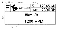
図7で例示された変速制御画面の上部には、第1領域101、第2領域102、第3領域103、第4領域104が横並び配置されており、変速制御画面の上部には、第5領域105と、第6領域106が縦並びで配置されている。第1領域101には、前後進切換機構32の状態(ここでは前進を示す「F」)が表示される。第2領域102には、副変速機構31の状態(ここでは高速段を示すウサギのイラスト)が表示される。第3領域103には、クルーズ走行の入り切りを示す記号が表示される。第4領域104には、時刻、エンジン使用時間、走行距離などから選択されたものが表示される。第5領域105には、走行速度が表示される。第6領域106には、エンジン回転数が表示される。
〔別実施の形態〕
(1)変速操作デバイスCSDは、上述のような多機能操作具5ではなく、レバー式やペダル式であってもよい。
(2)制動操作デバイスBDは、ブレーキペダル39以外の、作業車の走行に制動力を与えるような機器(例えばサイドクラッチなど)を操作するデバイスでもよい。
(3)ディスプレイ13は、アームレスト操作装置4とは別に、異なる位置に配置されてもよい。また、複数のディスプレイ13を備えて、互いにミラーリングするようにしてもよい。
(4)図6で示された機能ブロックは、説明目的で記載されているだけであり、それらの各機能部は、任意に統合することまたは任意に分割することが可能である。特に、演算制御装置800に構築されている各機能部は、互いにソフトウエア的に連係しているので、実際にはその機能は重なり合っている場合は多い。本発明は、図6で示されている機能部の区分けだけに、限定しているわけでない。
A
[Another embodiment]
(1) The shift operation device CSD may be a lever type or a pedal type instead of the
(2) The braking operation device BD may be a device for operating a device (for example, a side clutch) that gives a braking force to the traveling of the work vehicle other than the
(3) The
(4) The functional blocks shown in FIG. 6 are only described for the purpose of explanation, and each of those functional units can be arbitrarily integrated or arbitrarily divided. In particular, since the functional units constructed in the arithmetic and
本発明による走行作業車は、トラクタ以外、田植機、コンバインなどの農用作業車、あるいはフロントローダなどの建設土木作業車などに適用可能である。 The traveling work vehicle according to the present invention can be applied to agricultural work vehicles such as rice transplanters and combines, construction civil engineering vehicles such as front loaders, and the like in addition to tractors.
1 :車体
3 :トランスミッション
5 :多機能操作具
5A :グリップ本体
5B :揺動体
6A :走行制御ユニット
6B :変速制御ユニット
6C :車速取得部
7A :作業制御ユニット
7B :作業走行支援ユニット
8 :表示制御ユニット
9A :モード選択ボタン
13 :ディスプレイ
13A :タッチパネル
30 :無段変速機構
31 :副変速機構
38 :副変速操作具
39 :ブレーキペダル
60 :変速モード設定部
61 :上限速度設定部
62 :目標速度算定部
63 :目標速度強制変更部
64 :解除部
67 :車速制御部
68 :エンジン回転数指令部
81 :画面データ生成部
BD :制動操作デバイス
CSD :変速操作デバイス
1: Car body 3: Transmission 5:
Claims (6)
変速操作デバイスと、
前記走行作業車の上限速度を設定する上限速度設定部と、
前記変速操作デバイスの操作変位に基づいて、前記上限速度設定部によって設定されている上限速度に対する速度割合を算定して目標速度を決定する目標速度算定部と、
前記目標速度に基づいて前記エンジンの回転数、前記無段変速機構の変速比、またはそれら両方を調整する車速制御部と、
前記走行作業車の実車速を取得する車速取得部と、
前記走行作業車を制動操作する制動操作デバイスと、
前記制動操作デバイスの操作変位に基づいて前記目標速度を低速側に強制変更する目標速度強制変更部と、
前記変速操作デバイスの操作をトリガーとして、前記目標速度強制変更部によって強制変更された目標速度を解除して、前記目標速度を実車速に対応させる解除部と、
を備えた速度制御装置。 In a speed control device for a traveling work vehicle that drives a wheel by shifting rotational power from an engine through a continuously variable transmission mechanism,
A shift operation device;
An upper limit speed setting unit for setting an upper limit speed of the traveling work vehicle;
A target speed calculation unit that determines a target speed by calculating a speed ratio with respect to the upper limit speed set by the upper limit speed setting unit based on an operation displacement of the speed change operation device;
A vehicle speed control unit that adjusts the engine speed, the gear ratio of the continuously variable transmission mechanism, or both based on the target speed;
A vehicle speed acquisition unit for acquiring an actual vehicle speed of the traveling work vehicle;
A braking operation device for braking the traveling work vehicle;
A target speed forcibly changing unit for forcibly changing the target speed to a low speed side based on an operation displacement of the braking operation device;
Using the operation of the shift operation device as a trigger, the release unit for releasing the target speed forcibly changed by the target speed forcible change unit, and causing the target speed to correspond to the actual vehicle speed;
Speed control device with
Priority Applications (3)
| Application Number | Priority Date | Filing Date | Title |
|---|---|---|---|
| JP2014157699A JP6184380B2 (en) | 2014-08-01 | 2014-08-01 | Speed control device for traveling work vehicle |
| EP15174590.8A EP2965938B1 (en) | 2014-07-08 | 2015-06-30 | Speed control for working vehicle |
| US14/806,021 US9725090B2 (en) | 2014-08-01 | 2015-07-22 | Speed control for working vehicle |
Applications Claiming Priority (1)
| Application Number | Priority Date | Filing Date | Title |
|---|---|---|---|
| JP2014157699A JP6184380B2 (en) | 2014-08-01 | 2014-08-01 | Speed control device for traveling work vehicle |
Publications (2)
| Publication Number | Publication Date |
|---|---|
| JP2016035275A JP2016035275A (en) | 2016-03-17 |
| JP6184380B2 true JP6184380B2 (en) | 2017-08-23 |
Family
ID=55179198
Family Applications (1)
| Application Number | Title | Priority Date | Filing Date |
|---|---|---|---|
| JP2014157699A Active JP6184380B2 (en) | 2014-07-08 | 2014-08-01 | Speed control device for traveling work vehicle |
Country Status (2)
| Country | Link |
|---|---|
| US (1) | US9725090B2 (en) |
| JP (1) | JP6184380B2 (en) |
Families Citing this family (9)
| Publication number | Priority date | Publication date | Assignee | Title |
|---|---|---|---|---|
| US9964209B2 (en) * | 2015-05-14 | 2018-05-08 | Armin Sebastian Tay | Maximum axial position changing RPM methods |
| JP6701002B2 (en) * | 2016-06-23 | 2020-05-27 | 株式会社クボタ | Driving support system and work vehicle |
| JP7001540B2 (en) * | 2018-05-18 | 2022-01-19 | 株式会社クボタ | Work platform |
| KR20200119439A (en) * | 2019-04-09 | 2020-10-20 | 엘에스엠트론 주식회사 | Apparatus and Method for Controlling Traveling Speed of Agricultural Vehicle |
| DE102019206829A1 (en) * | 2019-05-10 | 2020-11-12 | Deere & Company | Drive system for a harvesting machine |
| JP6766240B1 (en) * | 2019-09-06 | 2020-10-07 | 株式会社クボタ | Work vehicle |
| US11511743B2 (en) * | 2019-12-17 | 2022-11-29 | Cnh Industrial Canada, Ltd. | System and method for controlling the speed of a work vehicle towing an implement |
| CN113492852A (en) * | 2020-03-18 | 2021-10-12 | 华为技术有限公司 | Vehicle cruise control method and device |
| US11793099B2 (en) * | 2020-11-10 | 2023-10-24 | Deere & Company | Harvester implement steering control system to prevent over-running harvester head end during turn |
Family Cites Families (10)
| Publication number | Priority date | Publication date | Assignee | Title |
|---|---|---|---|---|
| US8453772B2 (en) * | 2005-08-01 | 2013-06-04 | Albert W. Brown | Manually operated electrical control and installation scheme for electric hybrid vehicles |
| JP5101388B2 (en) | 2008-05-02 | 2012-12-19 | 株式会社クボタ | Shift operating device for work vehicle |
| JP5088260B2 (en) * | 2008-07-29 | 2012-12-05 | 井関農機株式会社 | Combine |
| JP2010216563A (en) * | 2009-03-16 | 2010-09-30 | Yanmar Co Ltd | Maximum speed control mechanism for work vehicle |
| JP2011133098A (en) * | 2009-12-25 | 2011-07-07 | Yanmar Co Ltd | Working vehicle |
| KR101224751B1 (en) * | 2010-01-21 | 2013-01-21 | 가부시끼 가이샤 구보다 | Speed control structure for work vehicle, information display structure therefor, and speed shift manipulating structure therefor |
| BR112012030656A2 (en) * | 2010-06-03 | 2016-08-16 | Polaris Inc | and electronic choke control method for a vehicle |
| JP5341839B2 (en) | 2010-08-19 | 2013-11-13 | 株式会社クボタ | Tractor transmission |
| JP5933296B2 (en) * | 2011-07-29 | 2016-06-08 | 株式会社クボタ | Vehicle shift control system |
| US20150329116A1 (en) * | 2012-12-20 | 2015-11-19 | CNH Industrial America, LLC | System And Method for Controlling the Operation of a Work Vehicle Having a Power Shift Transmission and a Proportional Parking Brake |
-
2014
- 2014-08-01 JP JP2014157699A patent/JP6184380B2/en active Active
-
2015
- 2015-07-22 US US14/806,021 patent/US9725090B2/en active Active
Also Published As
| Publication number | Publication date |
|---|---|
| JP2016035275A (en) | 2016-03-17 |
| US9725090B2 (en) | 2017-08-08 |
| US20160031443A1 (en) | 2016-02-04 |
Similar Documents
| Publication | Publication Date | Title |
|---|---|---|
| JP6184380B2 (en) | Speed control device for traveling work vehicle | |
| EP2965938B1 (en) | Speed control for working vehicle | |
| JP6247173B2 (en) | Lift control device for ground work equipment | |
| US9759319B2 (en) | Traveling work vehicle | |
| JP6373114B2 (en) | Shift display control device for traveling work vehicle | |
| US10151081B2 (en) | Work vehicle | |
| JP2019157543A (en) | Work vehicle | |
| JP4479325B2 (en) | PTO control device for tractor | |
| JP2022010724A (en) | Implement | |
| JP6891247B2 (en) | Lifting control device for ground work equipment | |
| JP2011141016A (en) | Working vehicle | |
| JP7388515B2 (en) | work vehicle | |
| JP2011133098A (en) | Working vehicle | |
| JP2018023402A (en) | Lift control device for ground working device | |
| JP2012001018A (en) | Tractor | |
| JP6843199B2 (en) | Work platform | |
| JP2016003707A (en) | Work vehicle | |
| JP5027596B2 (en) | Work vehicle | |
| JP6376941B2 (en) | Work vehicle | |
| AU2015202774A1 (en) | Working vehicle | |
| JP2016003706A (en) | Work vehicle | |
| JP2021036147A (en) | Work vehicle | |
| JP5896541B2 (en) | Work vehicle | |
| JP2021095959A (en) | Work vehicle | |
| JP2011140991A (en) | Working vehicle |
Legal Events
| Date | Code | Title | Description |
|---|---|---|---|
| A621 | Written request for application examination |
Free format text: JAPANESE INTERMEDIATE CODE: A621 Effective date: 20161223 |
|
| TRDD | Decision of grant or rejection written | ||
| A977 | Report on retrieval |
Free format text: JAPANESE INTERMEDIATE CODE: A971007 Effective date: 20170622 |
|
| A01 | Written decision to grant a patent or to grant a registration (utility model) |
Free format text: JAPANESE INTERMEDIATE CODE: A01 Effective date: 20170627 |
|
| A61 | First payment of annual fees (during grant procedure) |
Free format text: JAPANESE INTERMEDIATE CODE: A61 Effective date: 20170725 |
|
| R150 | Certificate of patent or registration of utility model |
Ref document number: 6184380 Country of ref document: JP Free format text: JAPANESE INTERMEDIATE CODE: R150 |