JP6174963B2 - Battery control system - Google Patents
Battery control system Download PDFInfo
- Publication number
- JP6174963B2 JP6174963B2 JP2013205254A JP2013205254A JP6174963B2 JP 6174963 B2 JP6174963 B2 JP 6174963B2 JP 2013205254 A JP2013205254 A JP 2013205254A JP 2013205254 A JP2013205254 A JP 2013205254A JP 6174963 B2 JP6174963 B2 JP 6174963B2
- Authority
- JP
- Japan
- Prior art keywords
- current
- battery
- temperature
- limit value
- value
- Prior art date
- Legal status (The legal status is an assumption and is not a legal conclusion. Google has not performed a legal analysis and makes no representation as to the accuracy of the status listed.)
- Active
Links
Images


Classifications
-
- H—ELECTRICITY
- H01—ELECTRIC ELEMENTS
- H01M—PROCESSES OR MEANS, e.g. BATTERIES, FOR THE DIRECT CONVERSION OF CHEMICAL ENERGY INTO ELECTRICAL ENERGY
- H01M10/00—Secondary cells; Manufacture thereof
- H01M10/42—Methods or arrangements for servicing or maintenance of secondary cells or secondary half-cells
- H01M10/44—Methods for charging or discharging
- H01M10/443—Methods for charging or discharging in response to temperature
-
- B—PERFORMING OPERATIONS; TRANSPORTING
- B60—VEHICLES IN GENERAL
- B60L—PROPULSION OF ELECTRICALLY-PROPELLED VEHICLES; SUPPLYING ELECTRIC POWER FOR AUXILIARY EQUIPMENT OF ELECTRICALLY-PROPELLED VEHICLES; ELECTRODYNAMIC BRAKE SYSTEMS FOR VEHICLES IN GENERAL; MAGNETIC SUSPENSION OR LEVITATION FOR VEHICLES; MONITORING OPERATING VARIABLES OF ELECTRICALLY-PROPELLED VEHICLES; ELECTRIC SAFETY DEVICES FOR ELECTRICALLY-PROPELLED VEHICLES
- B60L3/00—Electric devices on electrically-propelled vehicles for safety purposes; Monitoring operating variables, e.g. speed, deceleration or energy consumption
- B60L3/0023—Detecting, eliminating, remedying or compensating for drive train abnormalities, e.g. failures within the drive train
- B60L3/0046—Detecting, eliminating, remedying or compensating for drive train abnormalities, e.g. failures within the drive train relating to electric energy storage systems, e.g. batteries or capacitors
-
- B—PERFORMING OPERATIONS; TRANSPORTING
- B60—VEHICLES IN GENERAL
- B60L—PROPULSION OF ELECTRICALLY-PROPELLED VEHICLES; SUPPLYING ELECTRIC POWER FOR AUXILIARY EQUIPMENT OF ELECTRICALLY-PROPELLED VEHICLES; ELECTRODYNAMIC BRAKE SYSTEMS FOR VEHICLES IN GENERAL; MAGNETIC SUSPENSION OR LEVITATION FOR VEHICLES; MONITORING OPERATING VARIABLES OF ELECTRICALLY-PROPELLED VEHICLES; ELECTRIC SAFETY DEVICES FOR ELECTRICALLY-PROPELLED VEHICLES
- B60L58/00—Methods or circuit arrangements for monitoring or controlling batteries or fuel cells, specially adapted for electric vehicles
- B60L58/10—Methods or circuit arrangements for monitoring or controlling batteries or fuel cells, specially adapted for electric vehicles for monitoring or controlling batteries
- B60L58/12—Methods or circuit arrangements for monitoring or controlling batteries or fuel cells, specially adapted for electric vehicles for monitoring or controlling batteries responding to state of charge [SoC]
- B60L58/14—Preventing excessive discharging
-
- B—PERFORMING OPERATIONS; TRANSPORTING
- B60—VEHICLES IN GENERAL
- B60L—PROPULSION OF ELECTRICALLY-PROPELLED VEHICLES; SUPPLYING ELECTRIC POWER FOR AUXILIARY EQUIPMENT OF ELECTRICALLY-PROPELLED VEHICLES; ELECTRODYNAMIC BRAKE SYSTEMS FOR VEHICLES IN GENERAL; MAGNETIC SUSPENSION OR LEVITATION FOR VEHICLES; MONITORING OPERATING VARIABLES OF ELECTRICALLY-PROPELLED VEHICLES; ELECTRIC SAFETY DEVICES FOR ELECTRICALLY-PROPELLED VEHICLES
- B60L58/00—Methods or circuit arrangements for monitoring or controlling batteries or fuel cells, specially adapted for electric vehicles
- B60L58/10—Methods or circuit arrangements for monitoring or controlling batteries or fuel cells, specially adapted for electric vehicles for monitoring or controlling batteries
- B60L58/12—Methods or circuit arrangements for monitoring or controlling batteries or fuel cells, specially adapted for electric vehicles for monitoring or controlling batteries responding to state of charge [SoC]
- B60L58/15—Preventing overcharging
-
- B—PERFORMING OPERATIONS; TRANSPORTING
- B60—VEHICLES IN GENERAL
- B60L—PROPULSION OF ELECTRICALLY-PROPELLED VEHICLES; SUPPLYING ELECTRIC POWER FOR AUXILIARY EQUIPMENT OF ELECTRICALLY-PROPELLED VEHICLES; ELECTRODYNAMIC BRAKE SYSTEMS FOR VEHICLES IN GENERAL; MAGNETIC SUSPENSION OR LEVITATION FOR VEHICLES; MONITORING OPERATING VARIABLES OF ELECTRICALLY-PROPELLED VEHICLES; ELECTRIC SAFETY DEVICES FOR ELECTRICALLY-PROPELLED VEHICLES
- B60L58/00—Methods or circuit arrangements for monitoring or controlling batteries or fuel cells, specially adapted for electric vehicles
- B60L58/10—Methods or circuit arrangements for monitoring or controlling batteries or fuel cells, specially adapted for electric vehicles for monitoring or controlling batteries
- B60L58/16—Methods or circuit arrangements for monitoring or controlling batteries or fuel cells, specially adapted for electric vehicles for monitoring or controlling batteries responding to battery ageing, e.g. to the number of charging cycles or the state of health [SoH]
-
- B—PERFORMING OPERATIONS; TRANSPORTING
- B60—VEHICLES IN GENERAL
- B60L—PROPULSION OF ELECTRICALLY-PROPELLED VEHICLES; SUPPLYING ELECTRIC POWER FOR AUXILIARY EQUIPMENT OF ELECTRICALLY-PROPELLED VEHICLES; ELECTRODYNAMIC BRAKE SYSTEMS FOR VEHICLES IN GENERAL; MAGNETIC SUSPENSION OR LEVITATION FOR VEHICLES; MONITORING OPERATING VARIABLES OF ELECTRICALLY-PROPELLED VEHICLES; ELECTRIC SAFETY DEVICES FOR ELECTRICALLY-PROPELLED VEHICLES
- B60L58/00—Methods or circuit arrangements for monitoring or controlling batteries or fuel cells, specially adapted for electric vehicles
- B60L58/10—Methods or circuit arrangements for monitoring or controlling batteries or fuel cells, specially adapted for electric vehicles for monitoring or controlling batteries
- B60L58/24—Methods or circuit arrangements for monitoring or controlling batteries or fuel cells, specially adapted for electric vehicles for monitoring or controlling batteries for controlling the temperature of batteries
- B60L58/25—Methods or circuit arrangements for monitoring or controlling batteries or fuel cells, specially adapted for electric vehicles for monitoring or controlling batteries for controlling the temperature of batteries by controlling the electric load
-
- H—ELECTRICITY
- H02—GENERATION; CONVERSION OR DISTRIBUTION OF ELECTRIC POWER
- H02J—CIRCUIT ARRANGEMENTS OR SYSTEMS FOR SUPPLYING OR DISTRIBUTING ELECTRIC POWER; SYSTEMS FOR STORING ELECTRIC ENERGY
- H02J7/00—Circuit arrangements for charging or depolarising batteries or for supplying loads from batteries
- H02J7/0029—Circuit arrangements for charging or depolarising batteries or for supplying loads from batteries with safety or protection devices or circuits
- H02J7/00304—Overcurrent protection
-
- B—PERFORMING OPERATIONS; TRANSPORTING
- B60—VEHICLES IN GENERAL
- B60L—PROPULSION OF ELECTRICALLY-PROPELLED VEHICLES; SUPPLYING ELECTRIC POWER FOR AUXILIARY EQUIPMENT OF ELECTRICALLY-PROPELLED VEHICLES; ELECTRODYNAMIC BRAKE SYSTEMS FOR VEHICLES IN GENERAL; MAGNETIC SUSPENSION OR LEVITATION FOR VEHICLES; MONITORING OPERATING VARIABLES OF ELECTRICALLY-PROPELLED VEHICLES; ELECTRIC SAFETY DEVICES FOR ELECTRICALLY-PROPELLED VEHICLES
- B60L2240/00—Control parameters of input or output; Target parameters
- B60L2240/40—Drive Train control parameters
- B60L2240/52—Drive Train control parameters related to converters
- B60L2240/529—Current
-
- B—PERFORMING OPERATIONS; TRANSPORTING
- B60—VEHICLES IN GENERAL
- B60L—PROPULSION OF ELECTRICALLY-PROPELLED VEHICLES; SUPPLYING ELECTRIC POWER FOR AUXILIARY EQUIPMENT OF ELECTRICALLY-PROPELLED VEHICLES; ELECTRODYNAMIC BRAKE SYSTEMS FOR VEHICLES IN GENERAL; MAGNETIC SUSPENSION OR LEVITATION FOR VEHICLES; MONITORING OPERATING VARIABLES OF ELECTRICALLY-PROPELLED VEHICLES; ELECTRIC SAFETY DEVICES FOR ELECTRICALLY-PROPELLED VEHICLES
- B60L2240/00—Control parameters of input or output; Target parameters
- B60L2240/40—Drive Train control parameters
- B60L2240/54—Drive Train control parameters related to batteries
- B60L2240/545—Temperature
-
- B—PERFORMING OPERATIONS; TRANSPORTING
- B60—VEHICLES IN GENERAL
- B60L—PROPULSION OF ELECTRICALLY-PROPELLED VEHICLES; SUPPLYING ELECTRIC POWER FOR AUXILIARY EQUIPMENT OF ELECTRICALLY-PROPELLED VEHICLES; ELECTRODYNAMIC BRAKE SYSTEMS FOR VEHICLES IN GENERAL; MAGNETIC SUSPENSION OR LEVITATION FOR VEHICLES; MONITORING OPERATING VARIABLES OF ELECTRICALLY-PROPELLED VEHICLES; ELECTRIC SAFETY DEVICES FOR ELECTRICALLY-PROPELLED VEHICLES
- B60L2240/00—Control parameters of input or output; Target parameters
- B60L2240/80—Time limits
-
- H—ELECTRICITY
- H01—ELECTRIC ELEMENTS
- H01M—PROCESSES OR MEANS, e.g. BATTERIES, FOR THE DIRECT CONVERSION OF CHEMICAL ENERGY INTO ELECTRICAL ENERGY
- H01M10/00—Secondary cells; Manufacture thereof
- H01M10/60—Heating or cooling; Temperature control
- H01M10/63—Control systems
-
- Y—GENERAL TAGGING OF NEW TECHNOLOGICAL DEVELOPMENTS; GENERAL TAGGING OF CROSS-SECTIONAL TECHNOLOGIES SPANNING OVER SEVERAL SECTIONS OF THE IPC; TECHNICAL SUBJECTS COVERED BY FORMER USPC CROSS-REFERENCE ART COLLECTIONS [XRACs] AND DIGESTS
- Y02—TECHNOLOGIES OR APPLICATIONS FOR MITIGATION OR ADAPTATION AGAINST CLIMATE CHANGE
- Y02E—REDUCTION OF GREENHOUSE GAS [GHG] EMISSIONS, RELATED TO ENERGY GENERATION, TRANSMISSION OR DISTRIBUTION
- Y02E60/00—Enabling technologies; Technologies with a potential or indirect contribution to GHG emissions mitigation
- Y02E60/10—Energy storage using batteries
-
- Y—GENERAL TAGGING OF NEW TECHNOLOGICAL DEVELOPMENTS; GENERAL TAGGING OF CROSS-SECTIONAL TECHNOLOGIES SPANNING OVER SEVERAL SECTIONS OF THE IPC; TECHNICAL SUBJECTS COVERED BY FORMER USPC CROSS-REFERENCE ART COLLECTIONS [XRACs] AND DIGESTS
- Y02—TECHNOLOGIES OR APPLICATIONS FOR MITIGATION OR ADAPTATION AGAINST CLIMATE CHANGE
- Y02T—CLIMATE CHANGE MITIGATION TECHNOLOGIES RELATED TO TRANSPORTATION
- Y02T10/00—Road transport of goods or passengers
- Y02T10/60—Other road transportation technologies with climate change mitigation effect
- Y02T10/70—Energy storage systems for electromobility, e.g. batteries
Description
本発明は、二次電池に流れる電流を制御する電池制御システムに関する。 The present invention relates to a battery control system that controls a current flowing in a secondary battery.
電気自動車(EV)やプラグインハイブリッド自動車(PHEV)、ハイブリッド自動車(HEV)に搭載する電池システムは、直列もしくは並列に接続された二次電池、二次電池と負荷との電気的な接続のオンオフを制御するための開閉器や電流センサ等の電気的な部品から構成される。上記電池システムには、電池システムの過渡な使用を検知した場合に、二次電池からモータ等の負荷に流れる電流を制限する電池制御システムを備えている。そのような電池制御システムを備えることにより、電池システムを構成する二次電池や各種構成部品が熱的な制約から逸脱することを回避し、かつ二次電池の劣化による出力低下を抑制するようにしている。 Battery systems installed in electric vehicles (EV), plug-in hybrid vehicles (PHEV), and hybrid vehicles (HEV) include secondary batteries connected in series or in parallel, and on / off of the electrical connection between the secondary battery and the load. It consists of electrical parts such as a switch and a current sensor for controlling the current. The battery system includes a battery control system that limits a current flowing from a secondary battery to a load such as a motor when transient use of the battery system is detected. By providing such a battery control system, it is possible to avoid the secondary battery and various components constituting the battery system from deviating from thermal restrictions, and to suppress a decrease in output due to deterioration of the secondary battery. ing.
このような電池システムの電流制限方法としては、電流検出器により検出された電流値を二乗し、さらにその値を時系列に従って積算して電流二乗積算値を算出し、当該電流二乗積算値に基づいて、具体的には、当該電流二乗積算値が所定の閾値を上回った場合に、モータ等の負荷に流れる電流を制御するコントローラに出力制限値を送信し、バッテリからインバータへ流れる電流を制限する技術が知られている(例えば、特許文献1参照)。 As a current limiting method for such a battery system, the current value detected by the current detector is squared, and the current value is integrated according to a time series to calculate a current square integrated value. Based on the current square integrated value, Specifically, when the current square integrated value exceeds a predetermined threshold, the output limit value is transmitted to the controller that controls the current flowing through the load such as a motor, and the current flowing from the battery to the inverter is limited. A technique is known (see, for example, Patent Document 1).
ところで、電池システム実使用時では、電池の使われ方がユーザによって、様々に異なる。しかしながら、特許文献1に記載の技術では、予め規定された負荷パターンをもとに電流制限値を決定している。このため、実使用時に電池システムに入力される負荷パターンが、予め規定した負荷パターンよりも高負荷もしくは低負荷な場合、予め規定した電流制限値で電池システムに流れる電流を制限すると、過少もしくは過大に電流制限をかけてしまう可能性がある。結果として、電池システムが熱的な制約を逸脱したり、二次電池のエネルギーを十分に活用することが出来なくなるという問題がある。
By the way, when the battery system is actually used, how the battery is used varies depending on the user. However, in the technique described in
本発明の第1の態様は、蓄電器の電流を検知する電流検知部と、蓄電器の温度を検知する温度検知部と、所定時間窓における蓄電器の電流および温度の履歴に基づいて、電流値が電流制限値を越えないように蓄電器の電流を制限する制限制御を行う制御部と、を備える電池制御システムであって、制御部は、所定時間窓における温度の変化が所定範囲内である場合には、既に設定されている第1電流制限値により電流を制限し、所定時間窓における温度の変化が所定範囲外である場合には、第1電流制限値を異なる第2電流制限値に設定変更し、設定変更後の第2電流制限値により電流を制限し、第1電流制限値を第2電流制限値に設定変更する際に、温度の変化が所定範囲を上回る場合には、第2電流制限値を第1電流制限値よりも小さな値とし、温度の変化が所定範囲を下回る場合には、第2電流制限値を第1電流制限値よりも大きな値とすることを特徴とする。
本発明の第2の態様は、蓄電器の電流を検知する電流検知部と、蓄電器の温度を検知する温度検知部と、所定時間窓における蓄電器の電流および温度の履歴に基づいて、電流値が電流制限値を越えないように蓄電器の電流を制限する制限制御を行う制御部と、を備え、制御部は、所定時間窓における温度の変化が所定範囲内である場合には、既に設定されている第1電流制限値により電流を制限し、所定時間窓における温度の変化が所定範囲外である場合には、第1電流制限値を異なる第2電流制限値に設定変更し、設定変更後の第2電流制限値により電流を制限する電池制御システムであって、所定時間窓は、時間幅の異なる複数の時間窓で構成され、所定範囲は、複数の時間窓毎に設定され、制御部は、複数の時間窓の各々において温度の変化と対応する所定範囲とを比較し、該温度の変化が所定範囲内か所定範囲外かを判定し、その判定結果に基づいて、第1電流制限値または第2電流制限値により電流を制限することを特徴とする。
本発明の第3の態様は、蓄電器の電流を検知する電流検知部と、蓄電器の温度を検知する温度検知部と、所定時間窓における蓄電器の電流および温度の履歴に基づいて、電流値が電流制限値を越えないように蓄電器の電流を制限する制限制御を行う制御部と、を備え、制御部は、所定時間窓における温度の変化が所定範囲内である場合には、既に設定されている第1電流制限値により電流を制限し、所定時間窓における温度の変化が所定範囲外である場合には、第1電流制限値を異なる第2電流制限値に設定変更し、設定変更後の第2電流制限値により電流を制限する電池制御システムであって、制御部は、電流の履歴として、蓄電器の内部抵抗と電流検知部が検知する電流に基づく該蓄電器の発熱量を演算し、蓄電器の発熱量の演算結果と温度の変化とに基づいて制限制御を行うことを特徴とする。
本発明の第4の態様は、蓄電器の電流を検知する電流検知部と、蓄電器の温度を検知する温度検知部と、所定時間窓における蓄電器の電流および温度の履歴に基づいて、電流値が電流制限値を越えないように蓄電器の電流を制限する制限制御を行う制御部と、を備え、制御部は、所定時間窓における温度の変化が所定範囲内である場合には、既に設定されている第1電流制限値により電流を制限し、所定時間窓における温度の変化が所定範囲外である場合には、第1電流制限値を異なる第2電流制限値に設定変更し、設定変更後の第2電流制限値により電流を制限する電池制御システムであって、所定時間窓における電流通電時間の割合としてのDuty比を検知するDuty比検知部を備え、制御部は、Duty比検知部が検知したDuty比に基づいて第1および第2電流制限値を変化させることを特徴とする。
本発明の第5の態様による電池制御システムは、蓄電器の電流を検知する電流検知部と、蓄電器の温度を検知する温度検知部と、所定時間窓における蓄電器の電流および温度の履歴に基づいて、蓄電器の電力量の変化を制限する制限制御を行う制御部と、を備え、制御部は、電流の履歴として、蓄電器の内部抵抗と電流検知部が検知する電流に基づく該蓄電器の発熱量を演算し、蓄電器の発熱量の演算結果および温度の履歴に基づいて制限制御を行うことを特徴とする。
本発明の第6の態様による電池制御システムは、蓄電器の電流を検知する電流検知部と、蓄電器の温度を検知する温度検知部と、所定時間窓における蓄電器の電流および温度の履歴に基づいて、蓄電器の電力量の変化を制限する制限制御を行う制御部と、所定時間窓における電流通電時間の割合としてのDuty比を検知するDuty比検知部と、を備え、制御部は、Duty比検知部が検知したDuty比に基づいて電力量を変化させることを特徴とする。
According to a first aspect of the present invention , a current detection unit that detects a current of a capacitor, a temperature detection unit that detects a temperature of the capacitor, and a current value based on a history of the current and temperature of the capacitor in a predetermined time window A control unit that performs limit control to limit the current of the battery so as not to exceed the limit value, and the control unit is configured to control the temperature change in a predetermined time window within a predetermined range. The current is limited by the first current limit value that has already been set, and if the change in temperature in the predetermined time window is outside the predetermined range, the first current limit value is changed to a different second current limit value. When the current is limited by the second current limit value after the setting change and the first current limit value is changed to the second current limit value and the change in temperature exceeds a predetermined range, the second current limit value is set. The value is smaller than the first current limit value And then, if a change in the temperature is below the predetermined range, characterized by a second current limit value greater than the first current limit value.
According to a second aspect of the present invention, a current detection unit that detects a current of a capacitor, a temperature detection unit that detects a temperature of the capacitor, and a current value based on a history of the current and temperature of the capacitor in a predetermined time window A control unit that performs limit control to limit the current of the capacitor so as not to exceed the limit value, and the control unit is already set when the temperature change in the predetermined time window is within the predetermined range. When the current is limited by the first current limit value and the temperature change in the predetermined time window is outside the predetermined range, the first current limit value is set to a different second current limit value, and the first (2) A battery control system that limits a current by a current limit value, wherein the predetermined time window includes a plurality of time windows having different time widths, the predetermined range is set for each of the plurality of time windows, and the control unit includes: Temperature in each of multiple time windows The change is compared with a corresponding predetermined range, it is determined whether the temperature change is within the predetermined range or outside the predetermined range, and the current is limited by the first current limit value or the second current limit value based on the determination result It is characterized by doing.
According to a third aspect of the present invention, a current detection unit that detects a current of a capacitor, a temperature detection unit that detects a temperature of the capacitor, and a current value based on a history of the current and temperature of the capacitor in a predetermined time window A control unit that performs limit control to limit the current of the capacitor so as not to exceed the limit value, and the control unit is already set when the temperature change in the predetermined time window is within the predetermined range. When the current is limited by the first current limit value and the temperature change in the predetermined time window is outside the predetermined range, the first current limit value is set to a different second current limit value, and the first 2 A battery control system that limits a current by a current limit value, wherein the control unit calculates a calorific value of the capacitor based on an internal resistance of the capacitor and a current detected by the current detector as a current history, Calculated calorific value and And performing limitation control based on the change in the degree.
According to a fourth aspect of the present invention, a current detection unit that detects a current of a capacitor, a temperature detection unit that detects a temperature of the capacitor, and a current value based on a history of the current and temperature of the capacitor in a predetermined time window A control unit that performs limit control to limit the current of the capacitor so as not to exceed the limit value, and the control unit is already set when the temperature change in the predetermined time window is within the predetermined range. When the current is limited by the first current limit value and the temperature change in the predetermined time window is outside the predetermined range, the first current limit value is set to a different second current limit value, and the first 2 A battery control system that limits a current by a current limit value, and includes a duty ratio detection unit that detects a duty ratio as a ratio of current application time in a predetermined time window, and the control unit detects the duty ratio detection unit Dut And wherein varying the first and second current limit value on the basis of the ratio.
The battery control system according to the fifth aspect of the present invention is based on a current detector that detects the current of the battery, a temperature detector that detects the temperature of the battery, and a history of the current and temperature of the battery in a predetermined time window. A control unit that performs limit control to limit the change in the amount of power of the battery, and the control unit calculates the heat generation amount of the battery based on the internal resistance of the battery and the current detected by the current detector as a current history. The limiting control is performed based on the calculation result of the calorific value of the battery and the temperature history.
The battery control system according to the sixth aspect of the present invention is based on a current detection unit that detects the current of the battery, a temperature detection unit that detects the temperature of the battery, and a history of the current and temperature of the battery in a predetermined time window. A control unit that performs limit control to limit a change in the amount of power of the battery, and a duty ratio detection unit that detects a duty ratio as a ratio of a current application time in a predetermined time window, and the control unit includes a duty ratio detection unit The amount of electric power is changed based on the duty ratio detected by.
本発明によれば、電池システムの実使用状態に応じて適切な電流制限値を設定することができる。 According to the present invention, an appropriate current limit value can be set according to the actual use state of the battery system.
以下、図を参照して本発明を実施するための形態について説明する。以下に説明する実施形態では、プラグインハイブリッド自動車(PHEV)の蓄電装置に適用した場合を例に説明する。なお、以下に説明する実施例の構成は、ハイブリッド自動車(HEV)、電気自動車(EV)などの乗用車やハイブリッド鉄道車両といった産業用車両の電源を構成する蓄電装置の蓄電器制御回路にも適用できる。 Hereinafter, embodiments for carrying out the present invention will be described with reference to the drawings. In the embodiment described below, a case where the present invention is applied to a power storage device of a plug-in hybrid vehicle (PHEV) will be described as an example. The configuration of the embodiment described below can also be applied to a storage device control circuit of a power storage device that constitutes a power source for an industrial vehicle such as a passenger vehicle such as a hybrid vehicle (HEV) or an electric vehicle (EV) or a hybrid railway vehicle.
以下では、蓄電部を構成する蓄電器にリチウムイオン電池を適用した場合を例に挙げて説明するが、蓄電器としては、他にもニッケル水素電池や鉛電池、電気二重層キャパシタ、ハイブリッドキャパシタなどを用いることもできる。 In the following, a case where a lithium ion battery is applied to a capacitor constituting the power storage unit will be described as an example. However, as the capacitor, a nickel metal hydride battery, a lead battery, an electric double layer capacitor, a hybrid capacitor, etc. are used. You can also.
−第1の実施の形態−
本発明の第1の実施の形態について、図1乃至17に基づいて説明する。図1は、プラグインハイブリッド自動車に搭載された電池システムを説明する図である。
-First embodiment-
A first embodiment of the present invention will be described with reference to FIGS. FIG. 1 is a diagram for explaining a battery system mounted on a plug-in hybrid vehicle.
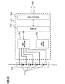
組電池110を備える電池システム10は、開閉器300,310を介してインバータ400に接続され、開閉器320,330を介して充電器420と接続される。インバータ400および充電器420は車両制御部200によって制御される。
The
車両走行中は、電池システム10はインバータ400と接続され、組電池110が蓄えているエネルギーによりモータジェネレータ410が駆動される。なお、車両制動時には、モータジェネレータ410は発電機として機能し、モータジェネレータ410から出力された三相交流電力はインバータ400によって直流電力に変換され、電池システム10に設けられた組電池110の充電に用いられる。充電の際には、電池システム10は充電器420と接続され、家庭用の電源または電気スタンドから電力が供給されることにより、組電池110が充電される。
While the vehicle is traveling, the
(電池システム10の構成)
電池システム10は、組電池110と、組電池110の状態を監視し制御する電池制御システム100とを備える。電池制御システム100は、単電池管理部120、電流検知部130、電圧検知部140と、組電池制御部150および記憶部180を備えている。組電池110は、複数の単電池111から構成される。単電池管理部120は、組電池110を構成する単電池111の状態を監視する。電流検知部130は、電池システム10に流れる電流を検知する。電圧検知部140は、組電池110の総電圧を検知する。組電池制御部150は組電池110の制御を行う。記憶部180は、組電池110、単電池111および単電池群112の電池特性に関する情報を格納する。
(Configuration of battery system 10)
The
組電池110は、電気エネルギーの蓄積及び放出(直流電力の充放電)が可能な複数の単電池111(リチウムイオン電池)を電気的に直列に接続して構成される。単電池111の出力電圧は、例えば、3.0〜4.2V(平均出力電圧:3.6V)である。もちろん、これ以外の電圧仕様のものでも構わない。
The assembled
組電池110は、電気的に直列に接続された複数の単電池111で構成される。組電池110を構成する複数の単電池111は、電池状態の管理および制御を行う都合上、所定数の単電池111で構成される複数の単電池群112にグループ分けされている。単電池群112は、例えば1個、4個、6個・・・のような所定の単位数で等区分とされる場合もあれば、4個の単電池111から成る単電池群112と6個の単電池111から成る単電池群112とを組み合わせるような複合区分とする場合もある。
The assembled
なお、本実施の形態では、説明を簡単にするために、組電池110は、4個の単電池111を電気的に直列に接続して成る2つの単電池群112a及び112bを、電気的に直列に接続して構成され、合計8個の単電池111を備える。
In this embodiment, in order to simplify the description, the assembled
単電池管理部120は、複数の単電池制御部121から構成されており、上記のようにグループ分けされた単電池群112に対して1つの単電池制御部121が割り当てられている。単電池制御部121は割り当てられた単電池群112からの電力を受けて動作し、単電池群112を構成する単電池111の状態を監視及び制御する。図1に示す例では、単電池管理部120には、2つの単電池群112a,112bに対応して2つの単電池制御部121a,121bが設けられている。
The unit
組電池制御部150には、単電池管理部120から送信される単電池111の電池電圧や温度、電流検知部130から送信される電池システム10に流れる電流値、電圧検知部140から送信される組電池110の総電圧値が入力される。組電池制御部150は、入力されたこれらの情報に基づいて組電池110の状態検知などを行う。組電池制御部150が行う処理の結果は、単電池管理部120や車両制御部200に送信される。
The assembled
組電池制御部150と単電池管理部120との間の信号の送受信は、フォトカプラのような絶縁素子170が設けられた信号通信部160により行われる。絶縁素子170を設けるのは、組電池制御部150の動作電圧と単電池管理部120の動作電源とが異なるためである。単電池管理部120は、組電池110から電力を受けて動作するのに対して、組電池制御部150は、車載補機用のバッテリ(例えば14V系バッテリ)を電源として用いている。
Signal transmission / reception between the assembled
絶縁素子170は、単電池管理部120を構成する回路基板に実装しても良いし、組電池制御部150を構成する回路基板に実装しても良い。尚、システム構成によっては、前記絶縁素子170を省略することも可能である。
The insulating
上述した単電池制御部121a,121bは、それぞれが監視する単電池群112a,112bの電位の高い順に従って、信号通信部160により直列に接続されている。組電池制御部150が送信した信号は、絶縁素子170を介して、信号通信部160により単電池制御部121aに入力される。単電池制御部121aの出力と単電池制御部121bの入力との間も同様に、信号通信部160により接続され、信号の伝送が行われる。
The unit
単電池制御部121bの出力は、絶縁素子170を介して、信号通信部160により組電池制御部150に伝送される。このように、組電池制御部150と単電池制御部121a,121bとは、信号通信部160によりループ状に接続されている。このループ接続は、デイジーチェーン接続あるいは数珠繋ぎ接続もしくは芋づる式接続と呼ぶ場合もある。なお、本実施の形態では、単電池制御部121aと単電池制御部121bとは、絶縁素子170を介さずに接続されているが、絶縁素子170を介して接続されていても良い。
The output of the
記憶部180には、電池システム10の電流制限特性や組電池110、単電池111、単電池群112の電池特性に関する情報が格納されている。電池特性としては、例えば、充電状態(SOC:State of Charge)と開回路電圧(OCV:Open Circuit Voltage)との関係を記述したデータテーブルや数式、内部抵抗特性や分極抵抗特性などをSOCや温度等各種パラメータとの対応関係を記述したデータテーブルや数式などがある。なお、本実施形態では、記憶部180は、組電池制御部150や単電池管理部120の外部に設置されている構成としたが、組電池制御部150または単電池管理部120が記憶部を備える構成とし、これに上記情報を格納してもよい。
The
(単電池制御部121の構成)
図2は、単電池制御部121の回路構成を示す図である。単電池制御部121は、電圧検出回路122、制御回路123、信号入出力回路124および温度検知部125を備える。電圧検出回路122は、各単電池111の端子間電圧を測定する。温度検知部125は、単電池群112の温度を測定する。制御回路123は、電圧検出回路122および温度検知部125から入力された測定結果を、信号入出力回路124を介して組電池制御部150に送信する。
(Configuration of unit cell control unit 121)
FIG. 2 is a diagram illustrating a circuit configuration of the unit
なお、周知の構成のため図示は省略したが、単電池制御部121には、自己放電や消費電流ばらつき等に伴い発生する単電池111間の電圧ばらつきを均等化する回路が、一般的に実装される。
Although not shown because of a well-known configuration, the single
単電池制御部121に設けられた温度検知部125は、単電池群112全体として1つの温度を測定し、その温度を、単電池群112を構成する単電池111の温度代表値として取り扱う。温度検知部125が測定した温度は、単電池111、単電池群112、または組電池110の状態を検知するための各種演算に用いられる。
The
なお、単電池111毎に温度検知部125を設けて単電池111毎に温度を測定し、単電池111毎の温度に基づいて各種演算を実行するようにしても構わない。ただし、この場合は、温度検知部125の数が多くなる分、単電池制御部121の構成が複雑となる。
Note that a
図2では、温度検知部125を簡易的に示したが、実際には温度測定対象に温度センサが設置され、その温度センサから温度情報としての電圧が出力される。この測定結果は、制御回路123を介して信号入出力回路124に送信され、信号入出力回路124によって単電池制御部121の外部に出力される。単電池制御部121には、この一連の流れを実現する機能が温度検知部125として実装されている。なお、温度情報(電圧)の測定には電圧検出回路122を用いることもできる。
In FIG. 2, the
(組電池制御部150の構成)
図3は、組電池制御部150の構成を示すブロック図である。組電池制御部150は、電流制限値決定部151と電池状態検知部152と電力制限演算部153とを備える。
(Configuration of battery pack controller 150)
FIG. 3 is a block diagram illustrating a configuration of the assembled
組電池制御部150には、単電池管理部120から出力される単電池111の電池電圧や温度の計測値、電流検知部130からの電流値、電圧検知部140から出力される組電池110の総電圧値、記憶部180に格納された単電池111の電池特性情報や後述する電流制限値、が入力される。また、単電池管理部120は、単電池111が過充電もしくは過放電であるかの診断を行う機能や、単電池管理部120に通信エラーなどが発生した場合に異常信号を出力する機能を有しており、それらの診断結果や異常信号も組電池制御部150に入力される。さらに、上位の制御装置である車両制御部200からも信号が入力される。
The assembled
組電池制御部150は、入力された情報、および記憶部180に予め記憶されている電流制限値や単電池111の電池特性に基づいて、組電池110の充放電を適切に制御するための電流制限値の演算、電力制限値の演算、単電池111のSOCや劣化状態(SOH:State Of Health)の演算、電圧均等化制御を行うための演算を実行する。組電池制御部150は、これらの演算結果や、その演算結果に基づく指令を、単電池管理部120や車両制御部200に出力する。
The assembled
(電流制限値決定部151の詳細説明)
図3に示した電流制限値決定部151について、図4を用いてさらに詳しく説明する。図4は、電流制限値決定部151の構成を示すブロック図である。電流制限値決定部151は、発熱量演算部1511、電流制限値修正判定部1512、電流制限値演算部1513を備えている。
(Detailed description of the current limit value determination unit 151)
The current limit
発熱量演算部1511は、電流検知部130が検知した電流に基づき組電池110もしくは単電池111の発熱量を演算する。電流制限値修正判定部1512は、発熱量演算部1511が演算した発熱量と温度検知部125が検知した電池温度とに基づき、電流制限値の修正要否を判定する。電流制限値演算部1513には、発熱量演算部1511からの出力(発熱量)と電流制限値修正判定部1512からの出力(電流制限値の修正要否判定)が入力される。電流制限値演算部1513は、これらの入力情報に基づいて記憶部180に予め格納されている電流制限値を修正し、修正後の電流制限値を出力する。なお、修正後の電流制限値は、予め格納されている電流制限値とは別に、記憶部180に格納される。
The heat generation
図5は、記憶部180に記憶されている電流制限特性の一例を示したものである。図5に示す電流制限特性は、時間窓毎の電流制限値を示したものである。電流制限値は、電流値を電池システム10の熱的な制約を逸脱することなく、劣化による出力低下を抑制するための値に制御するための制限値である。例えば、予め電池システム10に任意の電流波形を入力した実験等から、電池システム10の熱的な制約を逸脱させない、または、劣化の進行を促進させないような電流の平均値もしくは実効値を抽出し、これらを電流制限値とする。電池システム10に対する熱的な影響や劣化特性への影響は、電流が流れている時間に応じて異なる。そこで、本実施の形態では、図5に示すように時間窓に応じて電流制限値を設定するようにした。
FIG. 5 shows an example of the current limiting characteristic stored in the
図6は、時間窓Tw1〜Twnを説明する図である。図6では、ラインL1で示す電流値の時間変化に重ねて、時間窓Tw1〜Tw4を示した。なお、時間窓Tw4〜Twnの図示は省略した。時間窓はデータサンプリングする場合の時間幅を規定するものであり、図6に示す例では、現在時刻を基点として過去に遡った時間幅(時間窓)Tw1〜Tw4を、時刻T1と時刻T2に関して示したものである。時間の経過と共に、時間幅Tw1〜Tw4は図の右方向に移動することになり、それと共に、時間窓Tw1〜Tw4内のサンプリングデータも変化する。 FIG. 6 is a diagram for explaining the time windows Tw1 to Twn. In FIG. 6, the time windows Tw1 to Tw4 are shown so as to overlap the time change of the current value indicated by the line L1. The time windows Tw4 to Twn are not shown. The time window defines a time width when data sampling is performed. In the example shown in FIG. 6, time widths (time windows) Tw1 to Tw4 that are traced back to the past with the current time as a base point are related to time T1 and time T2. It is shown. As time elapses, the time widths Tw1 to Tw4 move to the right in the figure, and the sampling data in the time windows Tw1 to Tw4 also change.
記憶部180には、図5に示した電流制限特性が、図7に示すようなデータテーブルとして格納されている。また、データテーブルに代えて、時間窓と電流制限値の対応関係を数式などで表現しても良く、データテーブルという形に限定されるものではない。なお、電流制限値は、組電池110もしくは単電池111の熱的制約だけでなく、組電池110もしくは単電池111の劣化特性や開閉器300の部材の熱的制約等を考慮して決めても良い。
The
図8は、発熱量演算部1511の処理内容を示すブロック図である。発熱量演算部1511は、電流検知部130で検出された電流値I(A)と、記憶部180に格納されている単電池111の内部抵抗R(Ω)とに基づいて、以下の式(1)により時間窓Tw1〜Twn(sec)に応じた発熱量QTw1〜QTwn(J)を演算する。

発熱量演算部1511によって算出される発熱量QTw1〜QTwnは、図6に示すような時間窓Tw1〜Twn毎に取得される電流値Iiの計測データ(iはサンプリング周期毎に取得したデータのサンプル番号を示す)を用いて算出される。各演算結果は、発熱量演算部1511から出力される。なお、図8および式(1)では、内部抵抗の値を一定値としているが、SOCや温度に応じて内部抵抗の値を変更し、発熱量を演算しても良い。
Calorific value Q Tw1 to Q Twn calculated by the calorific
図9は、時間窓Tw1〜Twn毎の発熱量QTw1〜QTwnを説明する図であり、時間窓Tw1〜Tw4に関して示したものである。ラインL2は発熱量の累積値の時間変化を示している。発熱量QTw1〜QTw4は、時間窓Tw1〜Tw4において発生した発熱量に相当している。 Figure 9 is a diagram illustrating a calorific value Q Tw1 to Q Twn per time window Tw1~Twn, it illustrates with respect to time windows Tw1~Tw4. A line L2 indicates a change over time in the accumulated value of the heat generation amount. The calorific values Q Tw1 to Q Tw4 correspond to the calorific values generated in the time windows Tw1 to Tw4 .
本実施の形態では、発熱量を式(1)から演算する構成とし、以降の説明では、演算された発熱量に基づく電流制限値の修正及び決定方法について述べる。ただし、熱的な制約もしくは劣化による出力低下等を防ぐ指標となり得るパラメータは式(1)で示す発熱量に限定されるものではなく、例えば、組電池110もしくは単電池111に流れる電流の電流二乗積算値を時間窓に応じて以下の式(2)から演算し出力しても良いし、組電池110もしくは単電池111に流れる電流の平均値を時間窓に応じて以下の式(3)から演算し出力しても良い。さらにまた、ある時間窓幅毎の温度変化を演算し、出力する構成としても良い。
次に、電流制限決定部151における電流制限値修正判定部1512について説明する。図10は、電流制限値修正判定部1512を示すブロック図である。電流制限値修正判定部1512は、修正判定部15121、修正要否決定部15122を備えている。修正判定部15121は、時間窓Tw1〜Twn毎に設けられている。
Next, the current limit value
修正判定部15121は、発熱量演算部1511から入力される発熱量と温度検知部125から入力される電池温度とに基づいて、時間窓における発熱量と、その時間窓における温度変化とを時間窓Tw1〜Twn毎に比較し、その比較結果を出力する。まず、修正判定部15121は、発熱量演算部1511で算出された時間窓Tw1〜Twn毎の発熱量QTw1〜QTwnを、時間窓Tw1〜Twn毎に予め設定された発熱量の閾値Qth1〜Qthnと比較する。そして、修正判定部15121は、発熱量QTw1〜QTwnが閾値Qth1〜Qthnに到達したか否かを、時間窓Tw1〜Twn毎に判定する。
Based on the amount of heat input from the heat generation
修正判定部15121は、発熱量が閾値に達したと判定すると、温度検知部125で取得された温度の、時間窓における変化ΔTと、温度変化の閾値(下限閾値ΔTLT、上限閾値ΔTUT)との大小関係を比較する。温度変化の閾値は、時間窓Tw1〜Twn毎に設定されている。すなわち、時間窓の幅が大きい程、温度変化の閾値(下限閾値ΔTLT、上限閾値ΔTUT)も大きな値に設定される。この判定および比較は時間窓毎に行われ、その比較結果が修正判定部15121から出力される。図11は時間窓毎の温度変化を示す図である。図11において、ラインL3は温度の時系列的な変化を示す。また、温度Tcell1〜Tcell4は、時間窓Tw1〜Tw4の左端位置(開始位置)の時刻を示している。そして、各時間窓Tw1〜Tw4における温度変化ΔTTw1〜TTw4は、現在の時刻における温度Tcellと温度Tcell1〜Tcell4との差で表せる。
When the
比較結果としては、例えば、温度の変化ΔTが、閾値範囲よりも高い場合(ΔTUT≦ΔT)にフラグ「1」を出力し、温度の変化ΔTがある閾値範囲よりも低い場合(ΔT≦ΔTLT)にフラグ「2」を出力し、温度の変化ΔTが閾値範囲内(ΔTLT≦ΔT≦ΔTUT)に収まっている場合にはフラグ「0」を出力する。 As a comparison result, for example, when the temperature change ΔT is higher than the threshold range (ΔT UT ≦ ΔT), the flag “1” is output, and when the temperature change ΔT is lower than a certain threshold range (ΔT ≦ ΔT) The flag “2” is output to ( LT ), and when the temperature change ΔT is within the threshold range (ΔT LT ≦ ΔT ≦ ΔT UT ), the flag “0” is output.
次に、修正要否決定部15122について説明する。修正要否決定部15122には、時間窓Tw1〜Twn毎の判定結果が修正判定部15121から入力される。修正要否決定部15122は、時間窓Tw1〜Twn毎の判定結果に基づいて電流制限値を修正すべきか否かの判定を行い、その修正要否判定結果を出力する。修正要否判定結果出力としては、例えば、修正判定部15121から入力された複数のフラグの内、最も数の多かったフラグを出力する方法がある。また、後述する電流制限値の修正処理を時間窓毎に実行出来るように、修正判定部15121から時間窓毎に入力されたフラグを、そのまま時間窓毎に出力しても良い。さらにまた、修正判定部15122の修正判定結果を所定の回数分カウントしておき、カウントした結果に基づいて修正要否を決定し、出力する構成としても良い。
Next, the correction
図12は、電流制限値演算部1513を示すブロック図である。電流制限値演算部1513は、電流制限値修正部15131、電流制限判定部15132、電流制限値設定部15133を備えている。電流制限判定部15132は、時間窓Tw1〜Twn毎に設けられている。
FIG. 12 is a block diagram showing the current limit
電流制限値修正部15131は、図10に示した電流制限値修正判定部1512から入力された修正要否判定フラグに基づき、電流制限値の修正処理を実行する。その修正結果は記憶部180に記憶されると共に、電流制限判定部15132に出力される。図13は、電流制限値の修正処理を説明する図である。図13において、ラインL40は、現時点において設定されている電流制限特性である。車両起動時においては、予め記憶部180に記憶されている電流制限特性が、現時点の電流制限特性として設定される。入力された修正要否判定フラグが修正を要求するフラグであった場合には、電流制限特性の設定がラインL40から、ラインL41,L42に変更される。
The current limit
例えば、上述した修正要否決定部15122が、修正判定部15121から入力された複数のフラグの内、最も数の多かったフラグを出力する構成であった場合を考える。修正要求判定フラグが「1」であった場合、発熱量がその閾値を超えた複数の時間窓の内、時間窓幅内に取得した温度変化ΔTが上限閾値ΔTUTよりも高くなっている時間窓の数が最も多いことになる。この場合、現在の電流制限が過少(不足している)であると判断し、電流の制限を強める方向に電流制限特性を修正する。すなわち、図13のラインL40で示す電流制限特性をラインL41のように下方に修正し、全ての時間窓の電流制限値が小さくなるように修正する。その結果、電流制限がより強化される。
For example, consider the case where the above-described correction
一方、修正要求判定フラグが「2」であった場合、発熱量が閾値を超えているが温度変化ΔTが下限閾値ΔTLTよりも低くなっているので電流制限が過剰であると判断し、電流の制限を緩める方向に電流制限特性を修正する。すなわち、図13のラインL40で示す電流制限特性をラインL42のように上方に修正し、全ての時間窓の電流制限値が大きくなるように修正する。なお、修正要求判定フラグが「0」であった場合には、現在の電流制限が適切であると判断し、電流制限特性の修正は行わない。 On the other hand, when the correction request determination flag is “2”, it is determined that the current limit is excessive because the heat generation amount exceeds the threshold value but the temperature change ΔT is lower than the lower limit threshold value ΔT LT. The current limit characteristic is corrected so as to loosen the limit. That is, the current limiting characteristic indicated by the line L40 in FIG. 13 is corrected upward as indicated by the line L42 so that the current limiting values of all the time windows are increased. If the correction request determination flag is “0”, it is determined that the current limit is appropriate, and the current limit characteristic is not corrected.
また、上述したように、図10の修正要否決定部15122が、修正判定部15121から時間窓毎に入力されたフラグをそのまま時間窓毎に出力する構成の場合には、時間窓毎に電流制限値を修正しても良い。すなわち、電流制限特性L40を全体的に上方にまたは下方に修正するのではなく、電流制限値の修正処理を時間窓毎に行う。また、電流制限値の修正量は、例えば、修正判定要求フラグが「1」もしくは「2」となった場合に、1A電流制限値を下方修正もしくは上方修正するようにしても良いし、実際の温度上昇が、温度上昇閾値(ΔTUTもしくはΔTLT)を逸脱した場合に、実際の温度上昇と温度上昇閾値との差分に応じた修正量を予め決めておいても良い。
Further, as described above, in the case where the correction
次に、電流制限判定部15132について説明する。電流制限判定部15132には、電流制限値修正部15131からの修正後電流制限値と、発熱量演算部1511で算出された時間窓Tw1〜Twn毎の発熱量QTw1〜QTwnとが入力される。電流制限判定部15132は、時間窓に応じた発熱量QTw1〜QTwnの演算結果が発熱量の閾値Qth1〜Qthnに到達したかどうかを判定し、制限要求フラグを設定する。例えば、発熱量が閾値に到達した場合には制限要求フラグを「1」に設定し、到達していない場合には制限要求フラグを「0」に設定する。制限要求フラグを設定後、それを電流制限値設定部15133へ出力する。
Next, the current
次に、電流制限値設定部15133について説明する。電流制限値設定部15133は、制限判定部15132から入力された制限要求フラグに基づき電流制限値を設定する。電流制限値の設定方法としては、例えば、複数設定された時間窓のうち、発熱量が閾値よりも高いと判定された時間窓における電流制限値の中で最も値の小さなものを、電流制限値に設定する。なお、ここでの電流制限値には、時間窓における温度変化ΔTが閾値範囲を外れていてラインL40からラインL41,L42のように変更された場合には、変更後の電流制限値が用いられる。
Next, the current limit
(電池状態検知部152の詳細説明)
組電池制御部150を構成する電池状態検知部152について説明する。電池状態検知部152は、単電池制御部120が計測した単電池111の電圧と電流検知部130が取得した電流値、温度検知部125が取得した電池温度に基づき、単電池111のSOCやSOHを演算する。SOCは以下の式(4)に示すように、満充電時の容量Qmaxと現在電池が蓄えている容量Qremainの比として表される。また、内部抵抗に基づく劣化状態SOHRは、以下の式(5)で示されるように、新品時の内部抵抗R0と現在の内部抵抗R1との比として表される。ここでは、SOCやSOHRの演算方法については、公知のものとして説明を省略する。
The battery
(電力制限演算部153の詳細説明)
図14は、電力制限演算部153を示すブロック図である。電力制限演算部153には、電流制限値決定部151で決定された電流制限値、電池状態検知部152で演算されたSOC,SOHR、および温度検知部125で検出された電池温度が入力される。電力制限演算部153は、これらの入力値に基づいて、組電池110の電力制限値を演算し出力する。電力制限値は、電流制限値と、電流制限値に相当する電流が組電池110に通電した場合の組電池110の電圧と、に基づき、以下の式(6)により算出される。式(6)において、Nは組電池110を構成する単電池111の個数(個)、Ilimitは電流制限値(A)、OCVは開回路電圧(V)、R0は新品時の内部抵抗(Ω)、SOHRは劣化状態(%)を示す。
FIG. 14 is a block diagram showing the power
次に、図15、図16のフローチャートにより、電流制限動作および電流制限特性修正動作の一例を説明する。この処理は組電池制御部150において、所定時間間隔で繰り返し実行される。まず、図15に基づき、全体のフローを説明する。
Next, an example of the current limiting operation and the current limiting characteristic correcting operation will be described with reference to the flowcharts of FIGS. This process is repeatedly executed at predetermined time intervals in the assembled
ステップS100では、車両起動信号(車両が起動したかどうかを示す信号)を受信したかどうかを判定する。車両起動信号を受信したと判定されると、ステップS100からステップS110へ進む。 In step S100, it is determined whether a vehicle activation signal (a signal indicating whether the vehicle has been activated) has been received. If it determines with having received the vehicle starting signal, it will progress to step S110 from step S100.
ステップS110では、時間窓Tw1〜Twn毎の発熱量QTw1〜QTwnを演算すると共に電池温度を計測する。続くステップS120では、時間窓Tw1〜Twn毎に演算した発熱量QTw1〜QTwnが閾値Qth1〜Qthn以上か否かを時間窓Tw1〜Twn毎に判定する。ここで、全ての時間窓Tw1〜Twnに関して発熱量が閾値を下回っていると判定された場合は、ステップS110に戻る。一方、いずれかの時間窓において発熱量が閾値以上であった場合には、ステップS130へ進む。 In step S110, calorific values Q Tw1 to Q Twn are calculated for each of the time windows Tw1 to Twn, and the battery temperature is measured. In step S120, the calorific value Q Tw1 to Q Twn computed for each time window Tw1~Twn determines whether the threshold Q th1 to Q thn more per time window Tw1~Twn. Here, when it determines with the emitted-heat amount being less than a threshold value regarding all the time windows Tw1-Twn, it returns to step S110. On the other hand, if the heat generation amount is greater than or equal to the threshold value in any time window, the process proceeds to step S130.
ステップS130では、時間窓Tw1〜Twn毎に取得した温度変化ΔTTw1〜TTw4と、温度変化の閾値(下限値ΔTLT、上限値ΔTUT)と比較し、温度変化ΔTが上限値ΔTUTを上回っているか、または下限値ΔTLTを下回っているかを判定する。すなわち、温度変化ΔTが閾値範囲外か否かを判定する。ステップS130において、YES(範囲外)と判定されるとステップS140へ進み、NO(範囲内)と判定されるとステップS150へ進む。 In step S130, the temperature changes ΔT Tw1 to T Tw4 acquired for each of the time windows Tw1 to Twn are compared with the temperature change threshold values (lower limit value ΔT LT , upper limit value ΔT UT ), and the temperature change ΔT is compared with the upper limit value ΔT UT . It is determined whether it is above or below the lower limit value ΔT LT . That is, it is determined whether or not the temperature change ΔT is outside the threshold range. If it is determined as YES (out of range) in step S130, the process proceeds to step S140. If it is determined NO (in range), the process proceeds to step S150.
ステップS140では、電流制限値の修正処理を実行する。修正処理の詳細は後述する。ステップS150では、電流制限値を決定する。すなわち、ステップS130において温度変化ΔTが閾値範囲外と判定されると、電流制限値の修正を行って、修正後の電流制限値を用いて電流制限値の決定を行う。一方、ステップS130において温度変化ΔTが閾値範囲内と判定されると、修正を行う前の現在の電流制限値を用いて電流制限値の決定が行われる。ステップS160では、電流制限値をもとに電力制限値を決定する。 In step S140, current limit value correction processing is executed. Details of the correction process will be described later. In step S150, a current limit value is determined. That is, when it is determined in step S130 that the temperature change ΔT is outside the threshold range, the current limit value is corrected, and the current limit value is determined using the corrected current limit value. On the other hand, when it is determined in step S130 that the temperature change ΔT is within the threshold range, the current limit value is determined using the current current limit value before correction. In step S160, the power limit value is determined based on the current limit value.
図16は、ステップS140の電流制限値修正処理の一例を示すフローチャートである。まず、ステップS141では、時間窓内での温度変化ΔTが上限値ΔTUTを上回っているかどうかを判定する。ステップS141でΔT>ΔTUTと判定されるとステップS142へ進み、その他の場合にはステップS143へ進む。 FIG. 16 is a flowchart illustrating an example of the current limit value correction process in step S140. First, in step S141, it determines whether the temperature change [Delta] T in the time window exceeds the upper limit value [Delta] T UT. When it is determined that [Delta] T> [Delta] T UT at step S141 proceeds to step S142, the process proceeds to step S143 otherwise.
ステップS142では、温度変化ΔTが高い、つまり、組電池110もしくは単電池111が過剰に発熱している状態であると判定して、電流制限値を小さくするように(すなわち制限を強める方向に)修正する。ステップS143では、温度変化が低い、つまり、組電池110もしくは単電池111が発熱していない状態であると判定して、電流制限値を大きくするように(すなわち制限を緩める方向に)修正する。
In step S142, it is determined that the temperature change ΔT is high, that is, the assembled
本実施形態の効果について、図17に基づき述べる。図17(a)は、組電池110に流れる電流波形の一例を、図17(b)には、組電池110の温度波形の一例を、図17(c)には、時間窓Tw1における実効電流(もしくは、平均電流)の推移を示しており、時間窓がTw1、Tw2の2つの時間窓に基づき充放電を制御している場合の様子を示している。尚、ここでは、簡単のため、時間窓Tw1の区間における電流制限修正処理の効果のみを示した。つまり、時間窓Tw1での制限値が図17(c)におけるIth1からIth1´へと修正された場合の効果のみについて述べる。
The effect of this embodiment will be described with reference to FIG. FIG. 17A shows an example of a current waveform flowing through the assembled
車両が走行を開始し、時間窓Tw1区間内で、発熱量の演算値が閾値を越えたことを検知すると、電池温度の上昇ΔTTw1を検知する。Tw1経過時には、ΔTTw1が閾値の範囲内(ΔTLT≦ΔTTw1≦ΔTUT)にあるため、記憶部180に記憶しておいたTw1に対応する電流制限値(Ith1)を設定し、設定した電流制限値もしくは、電流制限値をもとに決定する電力制限値を逸脱しないよう充放電を制御する。
When the vehicle starts traveling and detects that the calculated value of the heat generation amount exceeds the threshold within the time window Tw1, the battery temperature rise ΔT Tw1 is detected. When Tw1 has elapsed, since ΔT Tw1 is within the threshold range (ΔT LT ≦ ΔT Tw1 ≦ ΔT UT ), a current limit value (I th1 ) corresponding to Tw1 stored in the
時間窓Tw2経過後においても同様に電池温度の上昇ΔTTw2を検知する。Tw2経過時には、図17(b)に示したように温度の波形(ラインL52)から計測した温度上昇(ΔTTw2)が温度上昇の下限閾値よりも小さい(ΔTTw2≦ΔTLT)ため、記憶部180に格納されている電流制限値では、過剰に電流を制限してしまうと判断し、電流制限値を予め記憶部180に記憶されていた各時間窓に対応する電流制限値を制限が緩和する方向へ修正する。つまり、ここでは、図17(c)に示すようにIth1からIth1´へと修正する。結果として、図17(c)のラインL53に示した電流制限値修正後の実効電流値(もしくは、平均電流値)は、図17(c)のラインL54が示している修正無しの場合に比べ、大きな値となる。また、図17(a)のラインL50の修正後の電流値も、ラインL51に示した修正無しの電流値に比べ、電流の絶対値が大きな値となる。図17では、修正後の電流制限値をもとに充放電を制御する例を説明したが、修正後の電流制限値をもとに決定する電力制限値をもとに充放電を制御してもよい。
Similarly, after the time window Tw2 elapses, the battery temperature increase ΔT Tw2 is detected. When Tw2 has elapsed, the temperature rise (ΔT Tw2 ) measured from the temperature waveform (line L52) as shown in FIG. 17B is smaller than the lower limit threshold for temperature rise (ΔT Tw2 ≦ ΔT LT ). It is determined that the current limit value stored in 180 excessively limits the current, and the limit of the current limit value corresponding to each time window in which the current limit value is stored in advance in the
図17に基づき、検知した温度上昇(ΔTTw2)が温度上昇下限閾値よりも小さい場合を例に挙げて説明したが、温度上昇上限閾値よりも大きい場合(ΔTTw2≧ΔTUT)は、電流制限を強める、つまり、電流制限値を小さな値に修正することになる。 The case where the detected temperature rise (ΔT Tw2 ) is smaller than the temperature rise lower limit threshold has been described as an example based on FIG. 17, but if the temperature rise is larger than the temperature rise upper limit threshold (ΔT Tw2 ≧ ΔT UT ), current limiting is performed. In other words, the current limit value is corrected to a small value.
また、温度の上昇度合いは、電池温度と電池の周囲温度の差分に応じて異なる。ある充放電パターンを入力すると温度が上昇するが、やがて、電池の発熱と放熱がバランスする点(電池の温度と周囲温度との差分に応じて大きくなる放熱量と、電池の発熱量が等しくなる点)に到達する。電池の発熱と放熱がバランスすると、充放電しているにも関わらず時間窓内での温度変化が小さくなるため、充放電しているにも関わらず時間窓における温度上昇が閾値を下回ると判定し、電流の制限を過剰に緩和してしまう可能性がある。このため、電池の周囲温度と現時点の温度との差分を求め、これに応じて、時間窓毎の温度上昇閾値(ΔTUTもしくはΔTLT)を決定するようにしても良い。 Further, the degree of temperature increase differs depending on the difference between the battery temperature and the ambient temperature of the battery. When a certain charge / discharge pattern is input, the temperature rises, but eventually, the point where the heat generation and heat dissipation of the battery are balanced (the heat dissipation amount that increases according to the difference between the battery temperature and the ambient temperature is equal to the heat generation amount of the battery) Point). When the heat generation and heat dissipation of the battery are balanced, the temperature change in the time window becomes small despite charging / discharging, so the temperature rise in the time window is determined to be below the threshold value despite charging / discharging. However, the current limitation may be excessively relaxed. Therefore, the difference between the ambient temperature of the battery and the current temperature may be obtained, and the temperature increase threshold value (ΔT UT or ΔT LT ) for each time window may be determined accordingly.
本実施形態によれば、電池の温度上昇に基づき、適切に電流制限値もしくは電力制限値を設定することが可能なため、電池の熱的な制約を逸脱させず、かつ、劣化による出力低下を抑制可能な充放電制御が実現できる。 According to the present embodiment, it is possible to appropriately set the current limit value or the power limit value based on the temperature rise of the battery, so that the output reduction due to deterioration does not deviate from the thermal restriction of the battery. Suppressible charge / discharge control can be realized.
−第2の実施の形態−
上述した第1の実施の形態では、電流制限値(もしくは電力制限値)を修正することによって、電池システムが熱的な制約を逸脱せず、かつ、二次電池の劣化による出力低下を抑制した充放電制御を実現できるようにした。以下に説明する第2の実施の形態では、組電池110の電流値もしくは、電力値を制限する代わりに、組電池110の電力量(単位:Wh)を制限することで、上記の問題を解消するようにした。
-Second Embodiment-
In the first embodiment described above, by correcting the current limit value (or power limit value), the battery system does not deviate from thermal restrictions and suppresses output reduction due to deterioration of the secondary battery. Charge / discharge control can be realized. In the second embodiment described below, instead of limiting the current value or power value of the assembled
本実施形態におけるプラグインハイブリッド自動車の蓄電装置の構成例は、図1と同様である。また、本実施形態における単電池制御部121の構成例は図2と同様であるが、た、組電池制御部150の構成のみが異なっている。以下では、構成の異なる組電池制御部について説明する。
A configuration example of the power storage device of the plug-in hybrid vehicle in the present embodiment is the same as FIG. Moreover, although the structural example of the
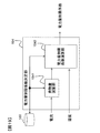
図18は、本実施形態における組電池制御部150Aを示すブロック図である。組電池制御部150Aは、図3に示す組電池制御部150に対応するものである。組電池制御部150Aは、電池状態検知部152A、電力量制限係数決定部154および電力量制限部155を備えている。
FIG. 18 is a block diagram showing an assembled battery control unit 150A in the present embodiment. The assembled battery control unit 150A corresponds to the assembled
電力量制限係数決定部154は、電流検知部130から入力された電流と温度検知部125から入力された電池温度とに基づいて、電力量を制限するための制限係数を決定する。電力量制限部155は、電力量制限係数決定部154が決定した制限係数と温度検知部125からの電池温度とに基づいて、電力量を演算する。電池状態検知部152Aは、第1の実施の形態の電池状態検知部152に対応するものであり、単電池111のSOCとSOHRに加え、単電池111の劣化状態SOHQを演算する。このSOHQは、劣化に伴う単電池111の満充電容量の減少率を示しており、新品時の満充電容量Qmax0と劣化後の満充電容量Qmaxとを用いて、以下の式(7)で定義される。ここでは、SOHQの演算方法は公知であるものとして詳細は省略する。
図19は、電力量制限係数決定部154を示すブロック図である。電力量制限係数決定部154は、発熱量演算部1541と電力量制限係数演算部1542とを備えている。なお、発熱量演算部1541は、第1の実施の形態の発熱量演算部1511と同様のものであり、図8に示した構成と同一構成を有しているので、ここでは説明を省略する。電力量制限係数演算部1542は、発熱量演算部1541で演算された発熱量Qと温度検知部125で計測された電池温度とに基づき、電力量制限係数を決定して出力する。
FIG. 19 is a block diagram showing the power amount limiting
電力量制限係数演算部1542は、時間窓毎に発熱量の閾値(Qth1〜Qthn)を設け、発熱量が閾値に到達すると、温度変化閾値(ΔTLT、ΔTUT)と取得した温度変化ΔTTwとを比較する。そして、いずれかの時間窓において、温度変化ΔTTwがΔTTw≧ΔTUTである場合に、例えば、1よりも小さい値を電力量制限係数として出力する。この電力量制限係数を、後述する電力量の演算結果に乗算することで、電力量を制限することができる。なお、ΔTLT≦ΔTTw≦ΔTUTである場合には、電力量制限係数=1(初期設定値)とする。
The power amount limiting
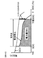
次に、図20,21を参照して、電力量制限部155について説明する。図20は、電力量の定義の一例を示す図であり、横軸はSOC、縦軸は電池電圧である。図20において、点線で示した波形は単電池111の開回路電圧(OCV)を示しており、実線で示す波形は、ある電流で通電した場合の電池電圧を示している。
Next, the power
単電池111にある電流を通電した場合には、図中の実線で示すように、単電池111の内部抵抗による電圧変化が生じる。放電時は、開回路電圧から内部抵抗による電圧変化分だけ電圧低下する。本実施の形態で説明する残電力量の定義は、例えば、以下の式(8)で演算される。すなわち、現時点のSOCから下限SOCに至るまでの電気量と電池電圧の積、つまり、図中のハッチングを施した部分となる。ここで、式(8)中の電池電圧は開回路電圧(OCV)と内部抵抗(R)と内部抵抗の上昇率(劣化状態SOHR)を用いて以下の式(9)で演算される。式(9)に含まれる電力量演算に用いる電流値は、固定値としても良いし、過去の電流履歴に基づいて可変としても良い。
また、式(8)中の電気量は、現時点のSOC(SOC)と下限SOC、新品時の満充電量Qmax0と満充電容量の減少率(SOHQ)を用いて、現時点のSOCから下限SOCまでに取り出せる電気量として、以下の式(10)から演算される。式(10)中の下限SOCは、車両が走行するのに最低限必要な出力を確保するためのSOCとして、温度と劣化状態の関数として定義しても良いし、固定値、例えば、実使用時における電池としての下限のSOCとして定義してもよい。
図21は、電力量制限部155を示すブロック図である。電力量制限部155に設けられた電力量演算部1551は、式(8)に基づいて電力量を演算する。その演算結果は、電力量制限係数決定部154から入力された制限係数が乗算されて、最終的な電力量として出力される。
FIG. 21 is a block diagram showing the power
図22に基づいて、本実施形態における発明の効果を説明する。図22には3つのグラフが示されており、上から順に、組電池110の充放電中の温度(ラインL61)、SOC(ラインL62)、電力量(ラインL63)の推移をプロットしたグラフを示す。
Based on FIG. 22, the effect of the invention in the present embodiment will be described. FIG. 22 shows three graphs. From the top, a graph plotting changes in temperature (line L61), SOC (line L62), and electric energy (line L63) during charging / discharging of the assembled
組電池110の充放電中に電池の過剰な温度上昇を検知した場合、つまり、各時間窓のいずれかにおいて、温度検知部125で検知した温度変化がある予め設定された温度変化の閾値よりも大きいことを検出した場合、電力量制限係数決定部154は制限係数を決定し、電力量を制限する。
When an excessive temperature rise of the battery is detected during charging / discharging of the assembled
過剰な温度上昇を検知して電力量が制限された場合、図22の実線で示す電力量の波形(ラインL63)のように、電力量の制限がない場合(破線で示すライン)と比較して演算結果が小さくなる。このため、組電池110の使用状態に応じた適切な電力量を演算することが可能となり、結果として電池システムの過渡な使用を回避することが出来る。
When the amount of power is limited by detecting an excessive temperature rise, as compared with the case where there is no limit on the amount of power (line indicated by a broken line) as shown by the waveform of the power amount shown by the solid line in FIG. 22 (line L63). The calculation result becomes smaller. For this reason, it becomes possible to calculate an appropriate amount of electric power according to the use state of the assembled
なお、上述した組電池制御部150Aの構成は一例を示したものであり、上述した構成(例えば、図21の構成)に何ら限定されるものではない。 The configuration of the assembled battery control unit 150A described above is merely an example, and is not limited to the configuration described above (for example, the configuration illustrated in FIG. 21).
−第3の実施の形態−
本発明の第3の実施の形態について、図23、図24に基づいて説明する。第3の実施の形態においては、ある一定期間の範囲内における通電時間の割合(以下、この割合をDuty比と呼ぶ)に応じて、電流を制限する。
-Third embodiment-
A third embodiment of the present invention will be described with reference to FIGS. In the third embodiment, the current is limited in accordance with a ratio of energization time within a certain period (hereinafter, this ratio is referred to as a Duty ratio).
本実施形態は、図3に示す組電池制御部150において、電流制限値決定部151の構成のみが第1実施形態と異なる。そのため、以下の説明では、第1実施形態と異なる電流制限値決定部151のみについて説明することにする。なお、本実施形態では電流制限値決定部に符号151Bを付した。図24は、電流制限値決定部151Bを示すブロック図である。
This embodiment differs from the first embodiment only in the configuration of the current limit
まず、図23を用いて、本実施形態におけるDuty比と電流制限特性との関係を説明する。図23(a)はDuty比の定義を説明する図であり、図23(b)はDuty比に応じた電流制限特性を示す図である。ところで、電池の劣化は、電池の使用状態に応じて異なる。特に、単電池111に、電流がどの程度の頻度で通電しているかによって異なる。そのため、図23(a)に示すように、ある一定期間、例えば、1日(=24時間)における通電時間をDuty比と定義する。すなわち、(Duty比)=(通電時間)/(一定時間)のように定義する。さらに、図23(b)のラインL71に示すように、Duty比に応じた電流制限値を定める。そして、電池システム設計時に、ユーザの使用頻度等に応じたDuty比に相当する電流制限値を、予め設定する。ラインL71は、そのようにして予め時間窓毎に設定された電流制限値を示したものであり、記憶部180に記憶されている。
First, the relationship between the duty ratio and the current limiting characteristic in this embodiment will be described with reference to FIG. FIG. 23A is a diagram for explaining the definition of the duty ratio, and FIG. 23B is a diagram showing the current limiting characteristic according to the duty ratio. By the way, the deterioration of the battery varies depending on the usage state of the battery. In particular, it differs depending on how often current is supplied to the
電池の使われ方はユーザによって様々に異なるため、図23(a)に示すDuty比もユーザによってそれぞれ異なる。そこで、本実施の形態では、図24に示すように、第1の実施の形態における電流制限値決定部151に、Duty比判定部1514を更に追加したものを電流制限値決定部151Bとした。
Since how the battery is used varies depending on the user, the duty ratio shown in FIG. 23A also varies depending on the user. Therefore, in this embodiment, as shown in FIG. 24, a current limit
そして、ある一定の期間内(例えば、1日(=24時間))の通電時間を計測してDuty比を算出し、これに応じて電流制限値を修正するようにした。つまり、電池システム使用中のDuty比が予め設定された電流制限特性に対応するDuty比よりも小さい場合には、電流制限を緩める方向に修正し(ラインL72)、電池システム使用中のDuty比が予め設定された電流制限特性に対応するDuty比よりも大きい場合は、電流制限を強める方向に修正する(ラインL73)。 Then, the duty ratio is calculated by measuring the energization time within a certain period (for example, one day (= 24 hours)), and the current limit value is corrected accordingly. That is, when the duty ratio during use of the battery system is smaller than the duty ratio corresponding to the preset current limit characteristic, the duty ratio is corrected so as to loosen the current limit (line L72), and the duty ratio during use of the battery system is If it is larger than the duty ratio corresponding to the preset current limit characteristic, the current limit is corrected so as to increase (line L73).
本実施の形態では、電池制御システム100は、第1の実施の形態の場合と同様の電流制限制御を行うことができると共に、さらに、組電池110の使用状態に応じた(Duty比に応じた)適切な電流制限値もしくは電力制限値を演算することが可能となる。その結果、電池システムの保護とエネルギーの最大活用を両立することが可能な電池制御システムを提供することが出来る。本実施の形態におけるDuty比に応じた制限処理は、上述した第1及び2の実施の形態の場合にも適用できる。
In the present embodiment, the
以上説明した実施の形態では、電池制御システム100は、単電池111の電流を検知する電流検知部130と、単電池111の温度を検知する温度検知部125と、所定時間窓Tw1〜Twnにおける単電池111の電流および温度の履歴(例えば、発熱量QTw1〜QTwn、温度変化ΔTTw1〜TTw4)に基づいて、電流値が電流制限値を越えないように単電池111の電流を制限する制限制御を行う制御部150と、を備える。そして、制御部150は、所定時間窓Tw1〜Twnにおける温度の変化ΔTTw1〜TTw4が所定範囲内(下限閾値ΔTLT以上で上限閾値ΔTUT以下)である場合には、既に設定されている第1電流制限値(図13のラインL40)により電流を制限し、所定時間窓Tw1〜Twnにおける温度の変化ΔTTw1〜TTw4が所定範囲外である場合には、第1電流制限値を異なる第2電流制限値(図13のラインL41,L42)に設定変更し、設定変更後の第2電流制限値により電流を制限する。
In the embodiment described above, the
予め設定された電流制限値は所定の負荷パターンを前提に設定されているので、従来のようにその電流制限値だけを用いて電流制限を行った場合、例えば高負荷パターンで電池が使用された場合には、電池温度が過剰に上昇して電池の熱的な制約を逸脱するおそれがある。逆に、低負荷パターンで使用した場合において、過剰に電流制限をしてしまう可能性がある。しかしながら、本実施の形態においては、上述のように電池の温度変化に応じて、電流制限値を変更するようにしているので、実使用状態に応じた電流制限を行うことができ、過小または過大に電流制限をしてしまうのを避けることができ、電流制限値を電池システムの状態に応じて適切に設定することができる。 Since the preset current limit value is set on the premise of a predetermined load pattern, when the current limit is performed using only the current limit value as in the conventional case, for example, the battery is used in a high load pattern. In some cases, the battery temperature may rise excessively and deviate from the thermal constraints of the battery. Conversely, when used in a low load pattern, there is a possibility of excessive current limiting. However, in the present embodiment, as described above, the current limit value is changed according to the temperature change of the battery, so that the current limit according to the actual use state can be performed, which is too small or too large. Current limit can be avoided, and the current limit value can be appropriately set according to the state of the battery system.
第2電流制限値は、温度の変化が所定範囲を上回る場合には第1電流制限値よりも小さな値とされ、温度の変化が所定範囲を下回る場合には第1電流制限値よりも大きな値とされるのが良い。 The second current limit value is set to a value smaller than the first current limit value when the temperature change exceeds a predetermined range, and is larger than the first current limit value when the temperature change falls below the predetermined range. It is good to be said.
さらに、所定時間窓を時間幅の異なる複数の時間窓Tw1〜Twnで構成し、複数の時間窓Tw1〜Twn毎の温度の変化を、時間窓Tw1〜Twn毎に設定された所定範囲と比較することにより、電池状態の把握をより正確に行うことができ、より適切な電流制限を行うことが可能となる。 Further, the predetermined time window is composed of a plurality of time windows Tw1 to Twn having different time widths, and a change in temperature for each of the plurality of time windows Tw1 to Twn is compared with a predetermined range set for each of the time windows Tw1 to Twn. As a result, the state of the battery can be grasped more accurately, and more appropriate current limitation can be performed.
さらに、電流制限値を用いた制限制御を行うと共に、電池状態および第1または第2電流制限値および電池状態に基づく電力制限値により、蓄電器から出力される電力を制限することで、単電池の劣化状態SOHR等を考慮した、より適切な制限制御を行うことができる。 Furthermore, while performing the limit control using the current limit value, by limiting the power output from the battery by the battery state, the first or second current limit value, and the power limit value based on the battery state, More appropriate restriction control can be performed in consideration of the degradation state SOHR and the like.
また、電池制御システム100は、単電池111の電流を検知する電流検知部130と、単電池111の温度を検知する温度検知部125と、所定時間窓Tw1〜Twnにおける単電池111の電流および温度の履歴に基づいて、単電池111の電力量の変化を制限する制限制御を行う制御部150と、を備える。このように、過剰な温度上昇を検知して電力量が制限された場合、図22のラインL63で示すように電力量の制限がない場合(破線で示すライン)と比較して演算結果が小さくなり、単電池111の過渡な使用を回避することが出来る。
In addition, the
なお、電流の履歴として、電池の熱的パラメータである、蓄電器の内部抵抗と前記電流検知部が検知する電流に基づく該蓄電器の発熱量や、電流検知部が検知する電流に基づく電流二乗積算値や、時間窓における電流区間平均値を用いても良い。 As the current history, the battery heat parameter, the amount of heat generated by the battery based on the internal resistance of the battery and the current detected by the current detector, and the current square integrated value based on the current detected by the current detector Alternatively, an average current section value in a time window may be used.
さらに、時間窓における電流通電時間の割合としてのDuty比を検知するDuty比検知部としてDuty比判定部1514を備え、Duty比判定部1514によるDuty比に基づいて第1および第2電流制限値を変化させる、すなわち、図13に示すラインL41,L42を、Duty比に基づいて、さらに図23(b)のラインL72,L73のように変化させる。その結果、電池の使用状態に応じた(Duty比に応じた)適切な電流制限値もしくは電力制限値を演算することが可能となり、電池システムの保護とエネルギーの最大活用を両立することが可能となる。
Furthermore, a duty
上述した各実施形態はそれぞれ単独に、あるいは組み合わせて用いても良い。それぞれの実施形態での効果を単独あるいは相乗して奏することができるからである。また、以上の説明はあくまで一例であり、本発明は上記実施の形態に何ら限定されるものではない。例えば、上述した実施形態では、複数の時間窓Tw1〜Twnを設定したが、本発明は、時間窓が一つの場合であっても同様に適用することができる。 Each of the embodiments described above may be used alone or in combination. This is because the effects of the respective embodiments can be achieved independently or synergistically. Moreover, the above description is an example to the last and this invention is not limited to the said embodiment at all. For example, in the above-described embodiment, a plurality of time windows Tw1 to Twn are set, but the present invention can be similarly applied even when there is one time window.
10:電池システム、100:電池制御システム、110:組電池、111:単電池、125:温度検知部、130:電流検知部、150,150A:組電池制御部、151,151B:電流制限値決定部、153:電力制限演算部、154:電力量制限係数決定部、155:電力量制限部、180:記憶部、1514:Duty比判定部、Tw1〜Twn:時間窓 10: battery system, 100: battery control system, 110: battery pack, 111: single battery, 125: temperature detector, 130: current detector, 150, 150A: battery controller, 151, 151B: current limit value determination Unit, 153: power limit calculation unit, 154: power amount limit coefficient determination unit, 155: power amount limit unit, 180: storage unit, 1514: Duty ratio determination unit, Tw1 to Twn: time window
Claims (12)
前記蓄電器の温度を検知する温度検知部と、
所定時間窓における前記蓄電器の電流および温度の履歴に基づいて、電流値が電流制限値を越えないように前記蓄電器の電流を制限する制限制御を行う制御部と、を備える電池制御システムであって、
前記制御部は、
前記所定時間窓における前記温度の変化が所定範囲内である場合には、既に設定されている第1電流制限値により電流を制限し、
前記所定時間窓における前記温度の変化が所定範囲外である場合には、前記第1電流制限値を異なる第2電流制限値に設定変更し、設定変更後の前記第2電流制限値により電流を制限し、
前記第1電流制限値を前記第2電流制限値に設定変更する際に、前記温度の変化が前記所定範囲を上回る場合には、前記第2電流制限値を前記第1電流制限値よりも小さな値とし、前記温度の変化が前記所定範囲を下回る場合には、前記第2電流制限値を前記第1電流制限値よりも大きな値とすることを特徴とする電池制御システム。 A current detector for detecting the current of the battery;
A temperature detector for detecting the temperature of the battery;
A control unit that performs limit control to limit the current of the battery so that the current value does not exceed a current limit value based on a history of current and temperature of the battery in a predetermined time window. ,
The controller is
If the change in temperature in the predetermined time window is within a predetermined range, the current is limited by the first current limit value that is already set,
When the change in temperature in the predetermined time window is out of a predetermined range, the first current limit value is changed to a different second current limit value, and the current is changed according to the second current limit value after the setting change. limited to,
When changing the setting of the first current limit value to the second current limit value, if the temperature change exceeds the predetermined range, the second current limit value is smaller than the first current limit value. The battery control system is characterized in that when the temperature change falls below the predetermined range, the second current limit value is set to a value greater than the first current limit value .
前記蓄電器の温度を検知する温度検知部と、
所定時間窓における前記蓄電器の電流および温度の履歴に基づいて、電流値が電流制限値を越えないように前記蓄電器の電流を制限する制限制御を行う制御部と、を備え、
前記制御部は、
前記所定時間窓における前記温度の変化が所定範囲内である場合には、既に設定されている第1電流制限値により電流を制限し、
前記所定時間窓における前記温度の変化が所定範囲外である場合には、前記第1電流制限値を異なる第2電流制限値に設定変更し、設定変更後の前記第2電流制限値により電流を制限する電池制御システムであって、
前記所定時間窓は、時間幅の異なる複数の時間窓で構成され、
前記所定範囲は、前記複数の時間窓毎に設定され、
前記制御部は、
前記複数の時間窓の各々において前記温度の変化と対応する前記所定範囲とを比較し、該温度の変化が所定範囲内か所定範囲外かを判定し、
その判定結果に基づいて、前記第1電流制限値または前記第2電流制限値により電流を制限することを特徴とする電池制御システム。 A current detector for detecting the current of the battery;
A temperature detector for detecting the temperature of the battery;
A control unit that performs limit control to limit the current of the capacitor so that the current value does not exceed the current limit value based on the current and temperature history of the capacitor in a predetermined time window,
The controller is
If the change in temperature in the predetermined time window is within a predetermined range, the current is limited by the first current limit value that is already set,
When the change in temperature in the predetermined time window is out of a predetermined range, the first current limit value is changed to a different second current limit value, and the current is changed according to the second current limit value after the setting change. A battery control system to limit,
The predetermined time window is composed of a plurality of time windows having different time widths,
The predetermined range is set for each of the plurality of time windows,
The controller is
Comparing the change in temperature with the predetermined range corresponding to each of the plurality of time windows to determine whether the change in temperature is within a predetermined range or out of a predetermined range;
A battery control system, wherein the current is limited by the first current limit value or the second current limit value based on the determination result.
前記制御部は、
前記制限制御を行うと共に、電池状態および前記第1または第2電流制限値に基づく電力制限値により、前記蓄電器から出力される電力を制限することを特徴とする電池制御システム。 The battery control system according to claim 1 or 2 ,
The controller is
A battery control system that performs the limit control and limits the power output from the battery by a power limit value based on a battery state and the first or second current limit value.
前記制御部は、
前記電流の履歴として、前記蓄電器の内部抵抗と前記電流検知部が検知する電流に基づく該蓄電器の発熱量を演算し、
前記蓄電器の発熱量の演算結果と前記温度の変化とに基づいて前記制限制御を行うことを特徴とする電池制御システム。 The battery control system according to any one of claims 1 to 3 ,
The controller is
As the current history, calculate the calorific value of the battery based on the internal resistance of the battery and the current detected by the current detector,
The battery control system, wherein the restriction control is performed based on a calculation result of a calorific value of the battery and a change in the temperature.
前記制御部は、
前記電流の履歴として、前記電流検知部が検知する電流に基づく電流二乗積算値を演算し、
前記電流二乗積算値の演算結果と前記温度の変化とに基づいて前記制限制御を行うことを特徴とする電池制御システム。 The battery control system according to any one of claims 1 to 3 ,
The controller is
As the current history, the current square integrated value based on the current detected by the current detection unit is calculated,
The battery control system, wherein the limit control is performed based on a calculation result of the current square integrated value and a change in the temperature.
前記制御部は、
前記電流の履歴として、前記所定時間窓における電流区間平均値を演算し、
前記電流区間平均値と前記温度の変化とに基づいて前記制限制御を行うことを特徴とする電池制御システム。 The battery control system according to any one of claims 1 to 3 ,
The controller is
As the current history, calculate the current interval average value in the predetermined time window,
The battery control system, wherein the limit control is performed based on the current section average value and the temperature change.
前記所定時間窓における電流通電時間の割合としてのDuty比を検知するDuty比検知部を備え、
前記制御部は、
前記Duty比検知部が検知したDuty比に基づいて前記第1および第2電流制限値を変化させることを特徴とする電池制御システム。 The battery control system according to any one of claims 1 to 3 ,
A duty ratio detection unit for detecting a duty ratio as a ratio of a current application time in the predetermined time window;
The controller is
The battery control system, wherein the first and second current limit values are changed based on the duty ratio detected by the duty ratio detection unit.
前記蓄電器の温度を検知する温度検知部と、
所定時間窓における前記蓄電器の電流および温度の履歴に基づいて、電流値が電流制限値を越えないように前記蓄電器の電流を制限する制限制御を行う制御部と、を備え、
前記制御部は、
前記所定時間窓における前記温度の変化が所定範囲内である場合には、既に設定されている第1電流制限値により電流を制限し、
前記所定時間窓における前記温度の変化が所定範囲外である場合には、前記第1電流制限値を異なる第2電流制限値に設定変更し、設定変更後の前記第2電流制限値により電流を制限する電池制御システムであって、
前記制御部は、
前記電流の履歴として、前記蓄電器の内部抵抗と前記電流検知部が検知する電流に基づく該蓄電器の発熱量を演算し、
前記蓄電器の発熱量の演算結果と前記温度の変化とに基づいて前記制限制御を行うことを特徴とする電池制御システム。 A current detector for detecting the current of the battery;
A temperature detector for detecting the temperature of the battery;
A control unit that performs limit control to limit the current of the capacitor so that the current value does not exceed the current limit value based on the current and temperature history of the capacitor in a predetermined time window,
The controller is
If the change in temperature in the predetermined time window is within a predetermined range, the current is limited by the first current limit value that is already set,
When the change in temperature in the predetermined time window is out of a predetermined range, the first current limit value is changed to a different second current limit value, and the current is changed according to the second current limit value after the setting change. A battery control system to limit,
The controller is
As the current history, calculate the calorific value of the battery based on the internal resistance of the battery and the current detected by the current detector,
The battery control system, wherein the restriction control is performed based on a calculation result of a calorific value of the battery and a change in the temperature.
前記蓄電器の温度を検知する温度検知部と、
所定時間窓における前記蓄電器の電流および温度の履歴に基づいて、電流値が電流制限値を越えないように前記蓄電器の電流を制限する制限制御を行う制御部と、を備え、
前記制御部は、
前記所定時間窓における前記温度の変化が所定範囲内である場合には、既に設定されている第1電流制限値により電流を制限し、
前記所定時間窓における前記温度の変化が所定範囲外である場合には、前記第1電流制限値を異なる第2電流制限値に設定変更し、設定変更後の前記第2電流制限値により電流を制限する電池制御システムであって、
前記所定時間窓における電流通電時間の割合としてのDuty比を検知するDuty比検知部を備え、
前記制御部は、
前記Duty比検知部が検知したDuty比に基づいて前記第1および第2電流制限値を変化させることを特徴とする電池制御システム。 A current detector for detecting the current of the battery;
A temperature detector for detecting the temperature of the battery;
A control unit that performs limit control to limit the current of the capacitor so that the current value does not exceed the current limit value based on the current and temperature history of the capacitor in a predetermined time window,
The controller is
If the change in temperature in the predetermined time window is within a predetermined range, the current is limited by the first current limit value that is already set,
When the change in temperature in the predetermined time window is out of a predetermined range, the first current limit value is changed to a different second current limit value, and the current is changed according to the second current limit value after the setting change. A battery control system to limit,
A duty ratio detection unit for detecting a duty ratio as a ratio of a current application time in the predetermined time window;
The controller is
The battery control system, wherein the first and second current limit values are changed based on the duty ratio detected by the duty ratio detection unit.
前記制御部は、
前記制限制御を行うと共に、電池状態および前記第1または第2電流制限値に基づく電力制限値により、前記蓄電器から出力される電力を制限することを特徴とする電池制御システム。 The battery control system according to claim 8 or 9 ,
The controller is
A battery control system that performs the limit control and limits the power output from the battery by a power limit value based on a battery state and the first or second current limit value.
前記蓄電器の温度を検知する温度検知部と、
所定時間窓における前記蓄電器の電流および温度の履歴に基づいて、前記蓄電器の電力量の変化を制限する制限制御を行う制御部と、を備え、
前記制御部は、
前記電流の履歴として、前記蓄電器の内部抵抗と前記電流検知部が検知する電流に基づく該蓄電器の発熱量を演算し、
前記蓄電器の発熱量の演算結果および前記温度の履歴に基づいて前記制限制御を行うことを特徴とする電池制御システム。 A current detector for detecting the current of the battery;
A temperature detector for detecting the temperature of the battery;
A control unit that performs restriction control to limit a change in the amount of electric power of the battery, based on the current and temperature history of the battery in a predetermined time window , and
The controller is
As the current history, calculate the calorific value of the battery based on the internal resistance of the battery and the current detected by the current detector,
The battery control system, wherein the limit control is performed based on a calculation result of a calorific value of the battery and a history of the temperature .
前記蓄電器の温度を検知する温度検知部と、
所定時間窓における前記蓄電器の電流および温度の履歴に基づいて、前記蓄電器の電力量の変化を制限する制限制御を行う制御部と、
前記所定時間窓における電流通電時間の割合としてのDuty比を検知するDuty比検知部と、を備え、
前記制御部は、
前記Duty比検知部が検知したDuty比に基づいて前記電力量を変化させることを特徴とする電池制御システム。 A current detector for detecting the current of the battery;
A temperature detector for detecting the temperature of the battery;
A control unit that performs restriction control to limit a change in the amount of electric power of the battery, based on a history of current and temperature of the battery in a predetermined time window;
A duty ratio detection unit that detects a duty ratio as a ratio of a current application time in the predetermined time window ;
The controller is
The battery control system characterized by changing the electric energy based on the duty ratio detected by the duty ratio detection unit .
Priority Applications (2)
| Application Number | Priority Date | Filing Date | Title |
|---|---|---|---|
| JP2013205254A JP6174963B2 (en) | 2013-09-30 | 2013-09-30 | Battery control system |
| PCT/JP2014/065835 WO2015045505A1 (en) | 2013-09-30 | 2014-06-16 | Battery control system |
Applications Claiming Priority (1)
| Application Number | Priority Date | Filing Date | Title |
|---|---|---|---|
| JP2013205254A JP6174963B2 (en) | 2013-09-30 | 2013-09-30 | Battery control system |
Publications (3)
| Publication Number | Publication Date |
|---|---|
| JP2015070753A JP2015070753A (en) | 2015-04-13 |
| JP2015070753A5 JP2015070753A5 (en) | 2016-04-21 |
| JP6174963B2 true JP6174963B2 (en) | 2017-08-02 |
Family
ID=52742663
Family Applications (1)
| Application Number | Title | Priority Date | Filing Date |
|---|---|---|---|
| JP2013205254A Active JP6174963B2 (en) | 2013-09-30 | 2013-09-30 | Battery control system |
Country Status (2)
| Country | Link |
|---|---|
| JP (1) | JP6174963B2 (en) |
| WO (1) | WO2015045505A1 (en) |
Cited By (1)
| Publication number | Priority date | Publication date | Assignee | Title |
|---|---|---|---|---|
| WO2020159065A1 (en) * | 2019-01-31 | 2020-08-06 | Samsung Electronics Co., Ltd. | Method of controlling charging of plurality of batteries and electronic device to which the method is applied |
Families Citing this family (9)
| Publication number | Priority date | Publication date | Assignee | Title |
|---|---|---|---|---|
| CN106249154B (en) | 2015-06-15 | 2020-11-03 | 株式会社杰士汤浅国际 | Secondary battery monitoring device, secondary battery protection system, battery pack, and vehicle |
| JP6467320B2 (en) * | 2015-09-09 | 2019-02-13 | 日立オートモティブシステムズ株式会社 | Storage battery control device |
| JP6787660B2 (en) | 2015-12-10 | 2020-11-18 | ビークルエナジージャパン株式会社 | Battery control device, power system |
| US10040366B2 (en) * | 2016-03-10 | 2018-08-07 | Ford Global Technologies, Llc | Battery terminal voltage prediction |
| JP2018093624A (en) * | 2016-12-02 | 2018-06-14 | 株式会社オートネットワーク技術研究所 | Power supply control device, power supply control method, and computer program |
| JP6858060B2 (en) * | 2017-04-10 | 2021-04-14 | 株式会社日立製作所 | Control method for railway vehicle drive system and railway vehicle power storage device |
| JP7001519B2 (en) * | 2018-03-27 | 2022-02-03 | ビークルエナジージャパン株式会社 | Battery management device, battery management method, power storage system |
| JPWO2021117902A1 (en) * | 2019-12-13 | 2021-06-17 | ||
| JP7226296B2 (en) * | 2019-12-19 | 2023-02-21 | トヨタ自動車株式会社 | vehicle, vehicle control system |
Family Cites Families (6)
| Publication number | Priority date | Publication date | Assignee | Title |
|---|---|---|---|---|
| JP4952031B2 (en) * | 2006-04-14 | 2012-06-13 | トヨタ自動車株式会社 | Power supply device, input / output restriction setting method in power supply device, vehicle and control method thereof |
| JP4784566B2 (en) * | 2006-07-12 | 2011-10-05 | 日産自動車株式会社 | Secondary battery input / output power control apparatus and input / output power control method |
| JP5268853B2 (en) * | 2009-10-08 | 2013-08-21 | 株式会社日立製作所 | Hybrid cruise control system |
| JP5554622B2 (en) * | 2010-04-21 | 2014-07-23 | 株式会社マキタ | Electric tool equipment |
| JP2011229319A (en) * | 2010-04-21 | 2011-11-10 | Makita Corp | Electric tool battery pack |
| US9590431B2 (en) * | 2011-12-22 | 2017-03-07 | Hitachi Automotive Systems, Ltd. | Battery controller, battery system |
-
2013
- 2013-09-30 JP JP2013205254A patent/JP6174963B2/en active Active
-
2014
- 2014-06-16 WO PCT/JP2014/065835 patent/WO2015045505A1/en active Application Filing
Cited By (2)
| Publication number | Priority date | Publication date | Assignee | Title |
|---|---|---|---|---|
| WO2020159065A1 (en) * | 2019-01-31 | 2020-08-06 | Samsung Electronics Co., Ltd. | Method of controlling charging of plurality of batteries and electronic device to which the method is applied |
| US11437839B2 (en) | 2019-01-31 | 2022-09-06 | Samsung Electronics Co., Ltd. | Method of controlling charging of plurality of batteries and electronic device to which the method is applied |
Also Published As
| Publication number | Publication date |
|---|---|
| WO2015045505A1 (en) | 2015-04-02 |
| JP2015070753A (en) | 2015-04-13 |
Similar Documents
| Publication | Publication Date | Title |
|---|---|---|
| JP6174963B2 (en) | Battery control system | |
| US10553896B2 (en) | Battery capacity degradation resolution methods and systems | |
| JP6496810B2 (en) | Battery control device and electric vehicle system | |
| JP5687340B2 (en) | Battery control device, battery system | |
| JP5819443B2 (en) | Battery control device, battery system | |
| JP5761378B2 (en) | Secondary battery control device and control method | |
| JP6101714B2 (en) | Battery control device, battery system | |
| US10554064B2 (en) | Battery controlling device | |
| CN106662620B (en) | Battery state detection device, secondary battery system, storage medium, and battery state detection method | |
| WO2014027389A1 (en) | Cell control device and secondary cell system | |
| US10574063B2 (en) | Method and system for balancing a battery pack | |
| WO2016009757A1 (en) | Battery state detection device, secondary battery system, program product, and battery state detection method | |
| JP2010019595A (en) | Residual capacity calculating apparatus of storage device | |
| JP2016128824A (en) | Battery life prediction method, battery system and battery controller | |
| WO2020085097A1 (en) | Battery control device |
Legal Events
| Date | Code | Title | Description |
|---|---|---|---|
| A521 | Request for written amendment filed |
Free format text: JAPANESE INTERMEDIATE CODE: A523 Effective date: 20160304 |
|
| A621 | Written request for application examination |
Free format text: JAPANESE INTERMEDIATE CODE: A621 Effective date: 20160304 |
|
| RD02 | Notification of acceptance of power of attorney |
Free format text: JAPANESE INTERMEDIATE CODE: A7422 Effective date: 20170126 |
|
| A131 | Notification of reasons for refusal |
Free format text: JAPANESE INTERMEDIATE CODE: A131 Effective date: 20170307 |
|
| A521 | Request for written amendment filed |
Free format text: JAPANESE INTERMEDIATE CODE: A523 Effective date: 20170420 |
|
| TRDD | Decision of grant or rejection written | ||
| A01 | Written decision to grant a patent or to grant a registration (utility model) |
Free format text: JAPANESE INTERMEDIATE CODE: A01 Effective date: 20170613 |
|
| A61 | First payment of annual fees (during grant procedure) |
Free format text: JAPANESE INTERMEDIATE CODE: A61 Effective date: 20170707 |
|
| R150 | Certificate of patent or registration of utility model |
Ref document number: 6174963 Country of ref document: JP Free format text: JAPANESE INTERMEDIATE CODE: R150 |
|
| RD04 | Notification of resignation of power of attorney |
Free format text: JAPANESE INTERMEDIATE CODE: A7424 Effective date: 20170927 |
|
| S111 | Request for change of ownership or part of ownership |
Free format text: JAPANESE INTERMEDIATE CODE: R313111 |
|
| R350 | Written notification of registration of transfer |
Free format text: JAPANESE INTERMEDIATE CODE: R350 |
|
| R250 | Receipt of annual fees |
Free format text: JAPANESE INTERMEDIATE CODE: R250 |
|
| R250 | Receipt of annual fees |
Free format text: JAPANESE INTERMEDIATE CODE: R250 |
|
| R250 | Receipt of annual fees |
Free format text: JAPANESE INTERMEDIATE CODE: R250 |
|
| R250 | Receipt of annual fees |
Free format text: JAPANESE INTERMEDIATE CODE: R250 |