JP6165470B2 - Motor control device, heat pump system and air conditioner - Google Patents
Motor control device, heat pump system and air conditioner Download PDFInfo
- Publication number
- JP6165470B2 JP6165470B2 JP2013041883A JP2013041883A JP6165470B2 JP 6165470 B2 JP6165470 B2 JP 6165470B2 JP 2013041883 A JP2013041883 A JP 2013041883A JP 2013041883 A JP2013041883 A JP 2013041883A JP 6165470 B2 JP6165470 B2 JP 6165470B2
- Authority
- JP
- Japan
- Prior art keywords
- phase
- pwm signal
- signal pattern
- current
- duty
- Prior art date
- Legal status (The legal status is an assumption and is not a legal conclusion. Google has not performed a legal analysis and makes no representation as to the accuracy of the status listed.)
- Active
Links
Images


Landscapes
- Control Of Ac Motors In General (AREA)
- Control Of Motors That Do Not Use Commutators (AREA)
Description
本発明の実施形態は、3相ブリッジ接続された複数のスイッチング素子をPWM制御することで、インバータ回路を介してモータを制御する制御装置,及びその制御装置を備えてなるヒートポンプシステム並びに空気調和機に関する。 Embodiments of the present invention provide a control device that controls a motor via an inverter circuit by PWM-controlling a plurality of switching elements connected in a three-phase bridge, a heat pump system including the control device, and an air conditioner About.
モータを制御するためにU,V,W各相の電流を検出する場合、インバータ回路の直流部に挿入した1つのシャント抵抗を用いて電流検出を行う技術がある。この方式で3相の全ての電流を検出するには、PWM(Pulse Width Modulation,パルス幅変調)キャリア(搬送波)の1周期内において、2相以上の電流を検出できるように3相のPWM信号パターンを発生させる必要がある。そのため、1周期内におけるPWM信号の位相をシフトさせることで常に2相以上の電流を、騒音を増大させること無く検出できるモータ制御装置が提案されている(特許文献1)。 When detecting the current of each phase of U, V, and W in order to control the motor, there is a technique of performing current detection using one shunt resistor inserted in the DC part of the inverter circuit. To detect all three-phase currents using this method, a three-phase PWM signal can be detected so that two or more currents can be detected within one cycle of a PWM (Pulse Width Modulation) carrier. It is necessary to generate a pattern. For this reason, there has been proposed a motor control device that can detect a current of two or more phases without increasing noise by shifting the phase of the PWM signal within one cycle (Patent Document 1).
また、3相モータをPWM制御する際には、3相変調方式と2相変調方式とがある。3相変調方式ではインバータ回路におけるスイッチング損失が増加することから、損失の増加を抑制する観点では2相変調方式を採用するのが望ましい。しかしながら、特許文献1に開示されている電流検出方式を採用すると、モータの低速回転領域では電流の検出が困難になるという問題がある。
When PWM control is performed on a three-phase motor, there are a three-phase modulation method and a two-phase modulation method. Since the switching loss in the inverter circuit increases in the three-phase modulation method, it is desirable to adopt the two-phase modulation method from the viewpoint of suppressing the increase in loss. However, when the current detection method disclosed in
そこで、スイッチング損失の増加を回避しつつ、1つの電流検出素子による電流検出方式を採用できるモータ制御装置,及びその制御装置を備えてなるヒートポンプシステム並びに空気調和機を提供する。 Accordingly, a motor control device that can employ a current detection method using one current detection element while avoiding an increase in switching loss, and a heat pump system and an air conditioner including the control device are provided.
実施形態のモータ制御装置によれば、電流検出手段は、インバータ回路の直流側に接続される電流検出素子が電流値に対応して発生した信号とPWM信号パターンとに基づいてモータの相電流を検出し、ロータ位置決定手段は、前記相電流に基づいてロータ位置を決定し、PWM信号生成手段は、ロータ位置に追従するように2相又は3相のPWM信号パターンを生成する。 According to the motor control apparatus of the embodiment, the current detection means calculates the phase current of the motor based on the signal generated by the current detection element connected to the DC side of the inverter circuit corresponding to the current value and the PWM signal pattern. Then, the rotor position determination means determines the rotor position based on the phase current, and the PWM signal generation means generates a two-phase or three-phase PWM signal pattern so as to follow the rotor position.
このとき、PWM信号生成手段は、3相のPWM信号パターンについては、3相のうち何れか1相は、搬送波周期の任意の位相を基準として遅れ側,進み側の双方向にデューティを増減させ、他の1相は、搬送波周期の任意の位相を基準として遅れ側,進み側の一方向に、残りの1相は前記方向とは逆方向にデューティを増減させる。 At this time, the PWM signal generation means increases / decreases the duty in both directions of the delay side and the advance side of any one of the three phases with respect to any phase of the carrier wave period for the three-phase PWM signal pattern. The other one phase increases or decreases the duty in one direction on the delay side and the advance side on the basis of an arbitrary phase of the carrier wave period, and the remaining one phase increases or decreases in the opposite direction to the above direction.
これにより、電流検出手段が、PWM信号の搬送波周期内で固定された2点のタイミングで2相の電流を検出可能となるように3相のPWM信号パターンを生成する。そして、切替え指令出力手段は、PWM信号生成手段に、モータが電流検出手段による電流検出可能期間が長くなる高速回転領域にある場合は2相のPWM信号パターンを生成させ、モータが前記電流可能期間が短くなる低速回転領域にある場合は3相のPWM信号パターンを生成させるように切替え指令を出力する。 As a result, the current detection means generates a three-phase PWM signal pattern so that a two-phase current can be detected at two timings fixed within the PWM signal carrier cycle. Then, the switching command output means causes the PWM signal generation means to generate a two-phase PWM signal pattern when the motor is in a high-speed rotation region where the current detection possible period by the current detection means is long , and the motor generates the current possible period. Is in a low-speed rotation region where the frequency becomes shorter , a switching command is output so as to generate a three-phase PWM signal pattern.
(第1実施形態)
以下、ヒートポンプシステムの一例として、空気調和機の圧縮機モータを駆動する第1実施形態について図1から図14を参照して説明する。図2において、ヒートポンプシステム1を構成する圧縮機(負荷)2は、圧縮部3とモータ4を同一の鉄製密閉容器5内に収容して構成され、モータ4のロータシャフトが圧縮部3に連結されている。そして、圧縮機2、四方弁6、室内側熱交換器7、減圧装置8、室外側熱交換器9は、熱伝達媒体流路たるパイプにより閉ループを構成するように接続されている。尚、圧縮機2は、例えばロータリ型の圧縮機であり、モータ4は、例えば3相IPM(Interior Permanent Magnet)モータ(ブラシレスDCモータ)である。空気調和機Eは、上記のヒートポンプシステム1を有して構成されている。
(First embodiment)
Hereinafter, as an example of a heat pump system, a first embodiment for driving a compressor motor of an air conditioner will be described with reference to FIGS. 1 to 14. In FIG. 2, the compressor (load) 2 constituting the
暖房時には、四方弁6は実線で示す状態にあり、圧縮機2の圧縮部3で圧縮された高温冷媒は、四方弁6から室内側熱交換器7に供給されて凝縮し、その後、減圧装置8で減圧され、低温となって室外側熱交換器9に流れ、ここで蒸発して圧縮機2へと戻る。一方、冷房時には、四方弁6は破線で示す状態に切り替えられる。このため、圧縮機2の圧縮部3で圧縮された高温冷媒は、四方弁6から室外側熱交換器9に供給されて凝縮し、その後、減圧装置8で減圧され、低温となって室内側熱交換器7に流れ、ここで蒸発して圧縮機2へと戻る。そして、室内側、室外側の各熱交換器7,9には、それぞれファン10,11により送風が行われ、その送風によって各熱交換器7,9と室内空気、室外空気の熱交換が効率良く行われるように構成されている。
At the time of heating, the four-
図1は、モータ制御装置の構成を示す機能ブロック図である。直流電源部21は、直流電源のシンボルで示しているが、商用交流電源から直流電源を生成している場合には、整流回路や平滑コンデンサ等を含んでいる。直流電源部21には、正側母線22a,負側母線22bを介してインバータ回路(直流交流変換器)23が接続されているが、負側母線22b側には電流検出素子であるシャント抵抗24が挿入されている。インバータ回路23は、スイッチング素子として例えばNチャネル型のパワーMOSFET25(U+,V+,W+,U−,V−,W−)を3相ブリッジ接続して構成されており、各相の出力端子はモータ4の各相巻線にそれぞれ接続されている。
FIG. 1 is a functional block diagram showing the configuration of the motor control device. The DC
シャント抵抗(電流検出素子)24の端子電圧(電流値に対応した信号)は電流検出部(電流検出手段)27により検出される。電流検出部27は、前記端子電圧をA/D変換して読み込むと、インバータ回路3に出力される2相又は3相のPWM信号パターンに基づいてU,V,W各相の電流Iu,Iv,Iwを検出する。電流検出部27が検出した各相電流は、ベクトル演算部(ロータ位置決定手段,PWM信号生成手段)30に入力される。
A terminal voltage (signal corresponding to the current value) of the shunt resistor (current detection element) 24 is detected by a current detection unit (current detection means) 27. When the
ベクトル演算部30では、制御条件を設定するマイクロコンピュータ等の機能部分よりモータ4の回転速度指令ωrefが与えられると、推定したモータ4の実際の回転速度との差分に基づいてトルク電流指令Iqrefが生成される。モータ4の各相電流Iu,Iv,Iwからはモータ4のロータ位置θが決定され、そのロータ位置θを用いるベクトル制御演算によりトルク電流Iq,励磁電流Idが算出される。トルク電流指令Iqrefとトルク電流Iqとの差分に対して例えばPI制御演算が行われ、電圧指令Vqが生成される。励磁電流Id側についても同様に処理されて電圧指令Vdが生成され、電圧指令Vq,Vdが上記ロータ位置θを用いて三相電圧Vu,Vv,Vwに変換される。三相電圧Vu,Vv,Vwは、DUTY生成部(PWM信号生成手段)31に入力され、各相のPWM信号を生成するためのデューティU_DUTY,V_DUTY,W_DUTYが決定される。
In the
各相デューティU,V,W_DUTYは、PWM信号生成部(PWM信号生成手段)32に与えられ、キャリアとのレベルが比較されることで2相又は3相PWM信号が生成される。また、2相又は3相PWM信号を反転させた下アーム側の信号も生成されて、必要に応じてデッドタイムが付加された後、それらが駆動回路33に出力される。駆動回路33は、与えられたPWM信号に従い、インバータ回路23を構成する6つのパワーMOSFET25(U+,V+,W+,U−,V−,W−)の各ゲートに、ゲート信号を出力する(上アーム側については、必要なレベルだけ昇圧した電位で出力する)。PWM信号生成部31が3相PWM信号を生成する方式については、例えば特許文献1に開示がある第4実施形態の方式を用いる。
Each phase duty U, V, W_DUTY is given to a PWM signal generation unit (PWM signal generation means) 32, and a two-phase or three-phase PWM signal is generated by comparing the level with the carrier. Further, a signal on the lower arm side obtained by inverting the two-phase or three-phase PWM signal is also generated, and after a dead time is added as necessary, they are output to the
その他、ベクトル演算部30は、トルク電流Iq及び励磁電流Idを消費電力演算部34に出力し、トルク電流Iq,励磁電流Id及び励磁電圧Vdに基づいて推定速度ωeを演算して消費電力演算部34及び検出方式選択部35に出力する。消費電力演算部34は、入力される各電流に基づいて消費電力Wを次式により演算すると、検出方式選択部(切替え指令出力手段)35に出力する。
W=ωe×T=ωe×P/2×{φ×Iq+(Ld−Lq)}×Id×Iq…(1)
但し、Tはモータ出力トルク,Pはモータ4の極数,φは電気子巻線鎖交磁束,Ldはd軸インダクタンス,Lqはq軸インダクタンスである。尚、消費電力演算部34については、第3実施形態で説明する。
In addition, the
W = ωe × T = ωe × P / 2 × {φ × Iq + (Ld−Lq)} × Id × Iq (1)
However, T is a motor output torque, P is the number of poles of the
負荷処理監視部(切替え指令出力手段)36は、PWM制御の1周期又は半周期毎に実行されるソフトウェア処理の実行時間を計測するためのタイマ36C(例えばフリーランカウンタ)を内蔵している。ベクトル演算部30と負荷処理監視部36とには、PWM信号生成部32からのPWM割り込み信号が入力されている。また、負荷処理監視部36には、PWM信号生成部32が内部で三角波のキャリアを生成するために使用するアップダウンカウンタのカウンタ値が入力されている。更に、負荷処理監視部36には、DUTY生成部31がPWM信号生成部32にPWMデューティパルスをセットしたタイミングで出力するDUTYセット信号が入力されている。尚、以上において、構成27〜36(駆動回路33を除く)の機能は、CPUを含むマイクロコンピュータのハードウェア及びソフトウェアにより実現される機能である。
The load processing monitoring unit (switching command output means) 36 has a built-in
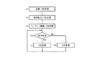
次に、本実施形態の作用について図3から図14を参照して説明する。図3は、エアコンによる冷房運転を開始させた場合における、圧縮機2に内蔵されるモータ4の回転数の変化と、PWM制御を2相変調,3相変調の何れで行うかの切り換え状態を示している。また、図4は、図3に対応した駆動制御方式の切り換えを概略的に示すフローチャートである。エアコンの運転が開始された圧縮機2の起動時には、3相変調でPWM制御を行う(S1)。モータ4の回転数が低い領域ではセンサレス駆動方式が実行できないため、強制転流によりモータ4を駆動する(S2)。そして、回転数がある程度上昇すると位置センサレス駆動方式に切り換える(S3)。
Next, the operation of the present embodiment will be described with reference to FIGS. FIG. 3 shows a change in the number of rotations of the
図3に示すように、エアコンの運転開始直後は、エアコンが設置されている部屋内の温度を迅速に低下させるためモータ4の回転数を急激に上昇させるが、その過程において、エアコンは室内温度を検出して所定の閾値(設定温度)と比較する(S4)。室内温度が閾値を下回っている間は(低い)3相変調を継続し(S5)、室内温度が閾値以上になると(高い)2相変調に切り換える(S6)。
As shown in FIG. 3, immediately after the start of the operation of the air conditioner, the rotational speed of the
運転開始直後に急激に出力を上昇させたことで室内温度が低下すると、図3に示すようにモータ4の回転数を低下させる。そして、室内温度が安定して閾値を下回る状態が継続すれば3相変調を継続し、何らかの要因により室内温度が上昇して閾値を超えれば2相変調に切り換えるようにする。
When the room temperature decreases due to a sudden increase in output immediately after the start of operation, the rotational speed of the
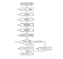
以降は、上述した2相変調と3相変調との切り換え制御について、より詳細に説明する。図2及び図3では、概略動作を説明するために閾値温度を用いて切り換えを説明したが、実際には以下のように制御する。図5は、エアコンの運転中における変調方式の切り換え処理を概略的に示すフローチャートである。先ず、現在実行中の変調方式が2相変調であればステップS11からS12に移行し、PWM割り込みを発生させる周期を、キャリア周期と同じ1周期毎にする。そして、2相変調に応じた電流検出方式により電流データを取得してベクトル制御処理を行い、2相PWM信号パターンを生成出力する(S13)。 Hereinafter, the switching control between the above-described two-phase modulation and three-phase modulation will be described in more detail. In FIG. 2 and FIG. 3, switching has been described using the threshold temperature in order to explain the general operation, but in actuality, control is performed as follows. FIG. 5 is a flowchart schematically showing a modulation system switching process during operation of the air conditioner. First, if the modulation method currently being executed is two-phase modulation, the process proceeds from step S11 to S12, and the cycle for generating a PWM interrupt is set to be the same as the carrier cycle. Then, current data is acquired by a current detection method according to two-phase modulation, vector control processing is performed, and a two-phase PWM signal pattern is generated and output (S13).
一方、現在実行中の変調方式が3相変調であればステップS11からS14に移行し、PWM割り込みを発生させる周期を、キャリア周期の半周期毎にする。そして、3相変調に応じた電流検出方式により電流データを取得してベクトル制御処理を行い、3相PWM信号パターンを生成出力する(S15)。尚、ステップS11における変調方式の選択は、後述するPWM処理負荷監視の結果に基づいて行われる。 On the other hand, if the modulation method currently being executed is three-phase modulation, the process proceeds from step S11 to S14, and the cycle for generating the PWM interrupt is set to every half cycle of the carrier cycle. Then, current data is acquired by a current detection method according to three-phase modulation, vector control processing is performed, and a three-phase PWM signal pattern is generated and output (S15). The selection of the modulation method in step S11 is performed based on the result of PWM processing load monitoring described later.
<2相変調処理>
以降は、2相変調処理について図6から図8を参照して説明する。図6は、2相変調を行う場合に、キャリア周期毎に実行される割り込み処理を示すフローチャートである。先ず、電流検出部27においてA/D変換されたデータを抽出すると(S21)、そのデータに基づいて3相電流を検出する(S22)。ここで、電流検出部27におけるシャント抵抗24の端子電圧のA/D変換処理は、図6に示す処理とは別個に1キャリア周期内で2回実行されており(実行タイミングについては後述する)、A/D変換されたデータは、例えばレジスタ等に格納されている。したがって、ステップS21の処理は、上記レジスタに格納されているデータを読み出すことになる。
<Two-phase modulation processing>
Hereinafter, the two-phase modulation process will be described with reference to FIGS. FIG. 6 is a flowchart showing interrupt processing executed for each carrier cycle when performing two-phase modulation. First, when A / D converted data is extracted in the current detector 27 (S21), a three-phase current is detected based on the data (S22). Here, the A / D conversion processing of the terminal voltage of the
次に、3相電流からベクトル制御演算によりモータ4のロータ位置(θ)を推定し(S23)、周波数制御(速度制御,S24)及び電流制御(PI制御等)を実行する(S25)。そして、今回の演算処理で決定された2相PWMデューティを次回の周期で出力するためレジスタやメモリ等に格納すると(S26)。(ここで得られた2相PWMデューティは、次のキャリア周期における割り込み処理のステップS27で出力レジスタにセットされる。)それから、前回のキャリア周期で決定された2相PWMデューティを、出力用のレジスタにセットする(S27)。
Next, the rotor position (θ) of the
図7は、2相変調時における割り込み処理の実行時間イメージを、PWMキャリア波形と共に示すものである。エアコンにおいては、1つの制御回路(マイコン)により、圧縮機2に並行して、室外機に対応する熱交換器9のファン11を駆動するモータも制御する(室内機に対応する熱交換器7のファン10を駆動するモータは、別の制御回路やドライバICなどにより制御される)。
FIG. 7 shows an execution time image of the interrupt process during the two-phase modulation together with the PWM carrier waveform. In the air conditioner, the motor that drives the
そこで、図7には、(a)に図6に示す圧縮機2のモータ制御に関する処理時間(1)を、(b)に上記ファン11のモータ(ファンモータ)制御に関する処理時間(2)を示している。すなわち、PWMキャリアである三角波のボトムにおいてPWM割り込みが発生すると、図6に示す処理を実行した後に、ファンモータについてもモータ電流を検出してベクトル制御を行う。
FIG. 7 shows a processing time (1) related to motor control of the
図8(a)は、2相変調の場合にPWMデューティパルスが出力される位相と、電流検出部27がシャント抵抗24の端子電圧をA/D変換するタイミングとを示している。この例では、U,V相のデューティパルスが三角波のボトムが中心位相となるように出力されている。1回目のA/D変換は上記ボトムのタイミングで実行される。この時検出される電流はW相の負電流となる。そして、2回目のA/D変換は、ボトムを起点として時間D2の経過後に、更にスイッチングディレイを考慮した微小時間αが経過した時点で実行される。この時検出される電流はU相の正電流となる。そして、V相電流は、上記2回のA/D変換結果に基づく演算で求められる。
FIG. 8A shows the phase at which the PWM duty pulse is output in the case of two-phase modulation, and the timing at which the
また、図8(b)は、ベクトル制御の過程で得られる直交電圧Vα,Vβに基づいて2相PWMデューティを算出するためのテーブルである。図8(b)の左方側,及び図8(c)に示すように、電圧Vα,Vβの大小関係に応じてセクタ0〜5が決定され、各セクタ毎に、パルス幅値D1,D2が電圧Vα,Vβと補正値Hとに基づいて決定される。尚、補正値Hは、直流電源部21の電圧であるDC電圧に応じてデューティパルス幅を補正する項であり、次式で表される。
H=√3×(PWMレジスタ最大値)×32768/(DC電圧) …(2)
尚、「PWMレジスタ最大値」は、例えばレジスタが16ビットであれば65535である。
FIG. 8B is a table for calculating the two-phase PWM duty based on the orthogonal voltages Vα and Vβ obtained in the vector control process. As shown in the left side of FIG. 8B and FIG. 8C,
H = √3 × (PWM register maximum value) × 32768 / (DC voltage) (2)
The “PWM register maximum value” is 65535 if the register is 16 bits, for example.
図8(b)の右方側に示すPWMa,PWMb,PWMcは、図1ではベクトル演算部が出力する3相電圧Vu,Vv,Vwに対応するもので、各セクタに応じてパルス幅値D1,D2の和となるか或いはパルス幅値D2のみ、若しくは「0」となる。 PWMa, PWMb, and PWMc shown on the right side of FIG. 8B correspond to the three-phase voltages Vu, Vv, and Vw output from the vector calculation unit in FIG. 1, and the pulse width value D1 corresponds to each sector. , D2 or only the pulse width value D2, or “0”.
<3相変調処理>
以降は、3相変調処理について図9から図12を参照して説明する。図9は、3相変調を行う場合に、キャリア周期の半周期毎に実行される割り込み処理を示すフローチャートである。ステップS31〜S35については、図6に示すステップS21〜S25と同様に実行されるが、続くステップS36では3相のPWMデューティが出力される。続くステップS37〜S39の処理は、DUTY生成部31において行われる。PWM信号生成部32より与えられるキャリアカウンタの値を参照し、アップカウント中か、ダウンカウント中かを判断する(S37)。アップカウント中であればD_Pwm_set2()をセットし(S38)、ダウンカウント中であればD_Pwm_set1()をセットする(S39)。これらについては図10及び図11で説明する。
<Three-phase modulation processing>
Hereinafter, the three-phase modulation process will be described with reference to FIGS. FIG. 9 is a flowchart showing interrupt processing executed every half cycle of the carrier cycle when three-phase modulation is performed. Steps S31 to S35 are executed in the same manner as steps S21 to S25 shown in FIG. 6, but in the subsequent step S36, a three-phase PWM duty is output. The subsequent steps S37 to S39 are performed in the DUTY generation unit 31. With reference to the value of the carrier counter provided from the PWM
図10は図7相当図であるが、3相変調の場合は、三角波のピークとボトムとにおいてPWM割り込みが発生する。図中に丸数字で示す処理(1)〜(4)については、処理(1)及び(3)はステップS31〜S37に対応し、処理(2),(4)はそれぞれステップS38,S39に対応している。この場合、ファンモータの制御(5)は、処理(4)を実行した後に行われる。 FIG. 10 is a diagram corresponding to FIG. 7, but in the case of three-phase modulation, a PWM interrupt occurs at the peak and bottom of the triangular wave. In the processes (1) to (4) indicated by circled numbers in the figure, the processes (1) and (3) correspond to steps S31 to S37, and the processes (2) and (4) correspond to steps S38 and S39, respectively. It corresponds. In this case, the fan motor control (5) is performed after the processing (4) is executed.
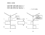
図11は、3相変調の場合における各相PWMデューティパルスの出力位相を示したもので、前述したように特許文献1に開示されている方式を用いる。すなわち、3相のうち何れか1相については、三角波のボトムを基準として遅れ側,進み側の双方向にデューティを増減させる。また、他の1相については、前記ボトムを基準として例えば進み位相側にデューティを増減させ、残りの1相については、前記ボトムを基準として遅れ位相側にデューティを増減させる。このように3相デューティパルスの出力位相を決定することで、電流検出部27が、キャリア周期内で固定された2点のタイミングで2相の電流を検出可能にしている。
FIG. 11 shows the output phase of each phase PWM duty pulse in the case of three-phase modulation. As described above, the method disclosed in
図11に示す例では、U相のパルスをキャリア周期の中心位相から双方方向にデューティを増減させ、V相のパルスを上記中心位相から進み方向にデューティを増減させ、W相のパルスを上記中心位相から遅れ方向にデューティを増減させている。三角波のピークで割り込みが発生するとキャリアカウンタはダウンカウント中であるから、D_Pwm_set2()により、今回のキャリア周期前半分のデューティパルスを出力する。 In the example shown in FIG. 11, the duty of the U-phase pulse is increased or decreased in both directions from the center phase of the carrier cycle, the duty of the V-phase pulse is increased or decreased from the center phase in the advance direction, and the W-phase pulse is increased to the center. The duty is increased or decreased from the phase in the delay direction. When an interrupt occurs at the peak of the triangular wave, the carrier counter is counting down, so the D_Pwm_set2 () outputs a duty pulse in the first half of the current carrier cycle.
U相については、デューティの1/2のパルスが、ピークでの割り込みが発生した後のタイミングからボトムまでの期間に出力される。V相については、デューティが50%未満であれば、そのパルスは、U相と同様にピークでの割り込みが発生した後のタイミングからボトムまでの期間に出力される。また、W相については、デューティが50%を超えると、その超えた分のパルスは、ピークでの割り込みが発生したタイミングからボトムに達するまでの期間に出力される。したがって、D_Pwm_set2()により出力されるのはこれらのパルスとなる。 For the U phase, a pulse with a duty of 1/2 is output in the period from the timing after the interruption at the peak to the bottom. For the V phase, if the duty is less than 50%, the pulse is output in the period from the timing after the interruption at the peak to the bottom as in the U phase. For the W phase, when the duty exceeds 50%, the excess pulses are output during the period from when the interrupt at the peak occurs until the bottom is reached. Therefore, these pulses are output by D_Pwm_set2 ().
一方、三角波のボトムで割り込みが発生するとキャリアカウンタはアップカウント中であるから、D_Pwm_set1()により、今回のキャリア周期後半分のデューティパルスを出力する。U相については、前半と同様にデューティの1/2のパルスが、ボトムでの割り込みが発生した後のタイミングからピークまでの期間に出力される。V相については、デューティが50%を超えると、その超えた分のパルスは、ボトムでの割り込みが発生したタイミングからピークに達するまでの期間に出力される。また、W相については、デューティが50%未満であれば、そのパルスは、U相と同様にボトムでの割り込みが発生した後のタイミングからピークまでの期間に出力される。したがって、D_Pwm_set1()により出力されるのはこれらのパルスとなる。 On the other hand, when an interrupt occurs at the bottom of the triangular wave, the carrier counter is counting up, so the D_Pwm_set1 () outputs a duty pulse for the latter half of the current carrier cycle. As for the U phase, as in the first half, a pulse having a duty of 1/2 is output in the period from the timing to the peak after the interruption at the bottom occurs. For the V phase, when the duty exceeds 50%, the excess pulses are output during the period from the timing when the interruption at the bottom occurs until the peak is reached. For the W phase, if the duty is less than 50%, the pulse is output in the period from the timing to the peak after the bottom interruption occurs, as in the U phase. Therefore, it is these pulses that are output by D_Pwm_set1 ().
そして、3相変調における2回のA/D変換タイミングは、三角波がボトムに達する直前と直後とする。前者のタイミングではW相電流が得られ、後者のタイミングではV相電流が得られることになる。尚、前者については、仮にボトムに一致するタイミングでA/D変換しても、各制御のタイミングや信号の遅れ等によりW相電流を得ることは可能である。 The two A / D conversion timings in the three-phase modulation are immediately before and after the triangular wave reaches the bottom. A W-phase current is obtained at the former timing, and a V-phase current is obtained at the latter timing. As for the former, even if A / D conversion is performed at the timing that coincides with the bottom, it is possible to obtain the W-phase current due to the timing of each control, signal delay, and the like.
図12は図8(b)相当図であるが、条件1〜3,セクタ,D1,D2については2相変調の場合と全く同様であり、PWMa,PWMb,PWMcの決定部分のみが異なっている。これらの決定には、パルス幅値D1,D2だけでなく、補正値Hの説明で述べたPWMレジスタの最大値PDも要素となっている。
FIG. 12 is a diagram corresponding to FIG. 8B, but
<変調方式切り換え処理>
次に、2相変調と3相変調とを切り換える制御の詳細について、図13及び図14を参照して説明する。図13は、処理負荷監視部36により実行される制御内容を中心に示すフローチャートである。ここでは、図3で説明した起動時においてモータ4の回転数が上昇する過程における3相から2相への切り替えと、モータ4が高速で回転しており2相変調を行っている状態から回転数が低下した際に、ソフトウェア処理負荷がより大きくなる3相変調への切り換えが可能か否かを判定する。
<Modulation method switching process>
Next, details of control for switching between two-phase modulation and three-phase modulation will be described with reference to FIGS. FIG. 13 is a flowchart mainly showing the control contents executed by the processing
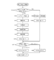
キャリア周期毎にPWM割り込みが発生すると、処理負荷監視部36はその時点でのタイマ36Cのカウンタ値(1)を読み込んで取得する(S41)。続くステップS42の「割り込み処理実行」とは、前述した図6又は図9に示す処理であり、ベクトル演算部30等で実行される(3相変調の実行時は半周期毎,2相変調の実行時は1周期毎)。ステップS27が実行されるとDUTY生成部31より出力されるDutyset信号がアクティブになる。これにより、処理負荷監視部36は再びタイマ36Cのカウンタ値(2)を読み込んで取得する(S43)。
When a PWM interrupt occurs every carrier cycle, the processing
次に、PWM信号生成部32より与えられるキャリアカウンタの値を参照し、カウンタがアップカウント中か否かを判断し(S44)、アップカウント中であれば(YES)割り込み処理時間(3)をカウンタ値(2),(1)の差分で得る(S45)。そして、割り込み処理時間(3)を許容される最大処理時間;MAX負荷Aと比較し、割り込み処理時間(3)がMAX負荷Aを超えていれば(S46:YES)、割り込み処理時間(3)をMAX負荷Aに設定する(S47)。割り込み処理時間(3)がMAX負荷A以下であれば(S45:NO)そのまま図13に示す処理を終了する。
Next, with reference to the value of the carrier counter given from the PWM
一方、ステップS44においてカウンタがダウンカウント中であれば(NO)割り込み処理時間(4)をカウンタ値(1),(2)の差分で得る(S48)。そして、割り込み処理時間(4)を許容される最大処理時間;MAX負荷Bと比較し、割り込み処理時間(4)がMAX負荷Bを超えていれば(S49:YES)、割り込み処理時間(4)をMAX負荷Bに設定する(S50)。割り込み処理時間(4)がMAX負荷B以下であれば(S45:NO)処理を終了する。例えば、キャリア周期が100μsであり、上記閾値がその50%である50μsに設定されていれば、割り込み処理時間(3)が50μsを超えた場合にMAX負荷A(50μs)に設定され、NG判定となる。 On the other hand, if the counter is counting down in step S44 (NO), the interrupt processing time (4) is obtained as the difference between the counter values (1) and (2) (S48). Then, the interrupt processing time (4) is compared with the maximum allowable processing time; MAX load B. If the interrupt processing time (4) exceeds the MAX load B (S49: YES), the interrupt processing time (4) Is set to the MAX load B (S50). If the interrupt processing time (4) is equal to or less than the MAX load B (S45: NO), the processing is terminated. For example, if the carrier cycle is 100 μs and the threshold value is set to 50 μs, which is 50%, the MAX load A (50 μs) is set when the interrupt processing time (3) exceeds 50 μs, and NG determination It becomes.
ここで、割り込み処理時間(3),(4)は「現行の処理時間の長さ」に対応する。また、MAX負荷A,Bは、割り込み処理時間(3),(4)を評価判定するための閾値であるが、これらは、キャリア周期の1/2以下となる値に設定すれば良い。 Here, the interrupt processing times (3) and (4) correspond to “the length of the current processing time”. The MAX loads A and B are threshold values for evaluating and determining the interrupt processing times (3) and (4), but these may be set to values that are ½ or less of the carrier period.
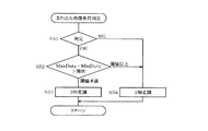
図14は、検出方式選択部35及び処理負荷監視部36により行われる割り込み処理負荷判定処理のフローチャートである。ステップS51では、割り込み処理時間(3)がMAX負荷Aに設定されているか否か、又は割り込み処理時間(4)がMAX負荷Bに設定されているか否かにより判定を行い、MAX負荷A又はBに設定されていれば(NG)、3相変調を実行中であれば2相変調に切り換える(S54)。
FIG. 14 is a flowchart of the interrupt processing load determination process performed by the detection
一方、MAX負荷A又はBに設定されていれなければ(OK)、デューティパルスについて、最大,最小のデューティ差(Maxduty−Minduty)を閾値と比較する(S52)。すなわち、3相変調時において、モータ4の回転数がある程度上昇したことで上記デューティ差が閾値以上になれば、キャリア周期内で2相分の電流を検出できる期間を十分確保でき(電流検出可能期間が長い)、安定した状態でモータ4の駆動制御ができる。したがって、ステップS54に移行する。また、上記デューティの差が閾値未満であれば、キャリア周期内で2相分の電流を検出できる期間が確保し難い(電流検出可能期間が短い)状態にある。したがって、基本的に電流検出率が高いメリットがある3相変調方式を維持する(S53)。
On the other hand, if the MAX load A or B is not set (OK), the maximum and minimum duty difference (Maxduty-Mindity) is compared with the threshold for the duty pulse (S52). In other words, during the three-phase modulation, if the above-mentioned duty difference becomes equal to or greater than the threshold value due to a certain increase in the rotation speed of the
以上のように本実施形態によれば、電流検出部27は、インバータ回路23の直流側に接続されるシャント抵抗24が電流値に対応して発生した信号とPWM信号パターンとに基づいてモータ4の相電流Iu,Iv,Iwを検出し、ベクトル演算部30は相電流に基づいてロータ位置θを決定し、PWM信号生成部32と共に、ロータ位置θに追従するように2相又は3相のPWM信号パターンを生成する。このとき、PWM信号生成部32は、3相のPWM信号パターンについては、何れか1相は、キャリア周期のボトムを基準として遅れ側,進み側の双方向にデューティを増減させ、他の1相は、前記ボトムを基準として遅れ側,進み側の一方向に、残りの1相は前記方向とは逆方向にデューティを増減させる。
As described above, according to the present embodiment, the
これにより、電流検出部27が、PWM信号の搬送波周期内で固定された2点のタイミングで2相の電流を検出可能となるように3相のPWM信号パターンを生成する。そして、検出方式選択部35は、DUTY生成部31及びPWM信号生成部32に、モータ4が高速回転領域にある場合は2相のPWM信号パターンを生成させてスイッチング損失の増大を抑制し、モータ4が低速回転領域にある場合は電流検出率が高い3相のPWM信号パターンを生成させるように切替え指令を出力する。したがって、スイッチング損失を抑制しつつ制御精度の向上を図ることができる。
Thus, the
また、検出方式選択部35及び処理負荷監視部36は、PWM信号のデューティ比,及びキャリア周期内における割り込み処理時間の長さ,或いはキャリア周期内における電流検出可能期間の長さを参照した結果に基づいて切替え指令を出力する。したがって、2相変調方式と3相変調方式との切り換えを、割り込み処理時間や電流検出可能期間の長さに基づいて妥当に行うことができる。
また、2相変調を行う場合はキャリア周期毎に割り込みを発生させ、3相変調を生成させる場合はキャリア周期の1/2毎に割り込みを発生させるので、従来一般的に実行されている2相変調に対し、特許文献1で提示された新規な3相変調方式を容易に導入できる。
Further, the detection
In addition, when performing two-phase modulation, an interrupt is generated every carrier cycle, and when generating three-phase modulation, an interrupt is generated every half of the carrier cycle. For modulation, the novel three-phase modulation method presented in
また、処理負荷監視部36は、2相変調方式の実行中はPWM割り込み処理に要する時間を計測し、その割り込み処理時間がキャリア周期の1/2以下に設定される閾値未満であれば3相変調方式に移行させ、割り込み処理時間が閾値以上であれば2相変調方式を維持するように切替え指令を出力する。したがって、PWM割り込み処理に要する時間を評価して、3相変調方式が確実に実行可能である場合に移行することができる。
Further, the processing
また、処理負荷監視部36は、3相変調方式の実行中に、3相のPWMデューティについて最大値と最小値との差を求め、それらのデューティ差が所定の閾値以上であれば2相変調方式に移行させるように切替え指令を出力する。したがって、電流検出率を評価して、2相変調方式が確実に実行可能である場合に移行することができる。
更に、圧縮機2と、室外側熱交換器9と、減圧装置8と、室内側熱交換器7とを備えるヒートポンプシステム1を備える空気調和機について、圧縮機2を構成するモータ4を制御対象とするので、ヒートポンプシステム1及び空気調和機の運転効率を向上させることができる。
Further, the processing
Furthermore, about the air conditioner provided with the
(第2実施形態)
図15及び図16は第2実施形態を示す図9及び図10相当図であり、第2実施形態と同一部分には同一符号を付して説明を省略し、以下異なる部分について説明する。図15に示すように、第2実施形態では、図9に示すフローチャートにステップS30,S35a,S36aを追加し、ステップS36を実行する箇所を変更している。すなわち、ステップS35を実行すると、フラグM_Int_flgを「1」にセットする(S35a)。上記のフラグは、既にキャリアの半周期においてステップS31〜S35の処理が実行済みであることを示す。
(Second Embodiment)
FIGS. 15 and 16 are views corresponding to FIGS. 9 and 10 showing the second embodiment. The same parts as those of the second embodiment are denoted by the same reference numerals, the description thereof is omitted, and different parts will be described below. As shown in FIG. 15, in 2nd Embodiment, step S30, S35a, S36a is added to the flowchart shown in FIG. 9, and the location which performs step S36 is changed. That is, when step S35 is executed, the flag M_Int_flg is set to “1” (S35a). The above flag indicates that the processing of steps S31 to S35 has already been executed in the half cycle of the carrier.
そして、冒頭のステップS30において、フラグM_Int_flg=0(リセット)か否かを判断し、「1(セット)」であれば(NO)ステップS36を実行し、フラグM_Int_flgを「0」にする(S36a)。ステップS35a,36aを実行すると、ステップS37に移行する。つまり、第2実施形態では、3相変調を実行する際のPWM割り込み処理では、周期の前半でステップS30〜S35a,S37〜S39を実行し、周期の後半でステップS30,S36,S36a,S37〜S39を実行することになる。 Then, in step S30 the beginning, it is determined whether the flag M_Int_flg = 0 (reset), perform a "1 (Se Tsu g)" if (NO) step S36, the flag M_Int_flg to "0" (S36a). If step S35a, 36a is performed, it will transfer to step S37. That is, in the second embodiment, in the PWM interrupt processing when performing three-phase modulation, steps S30 to S35a and S37 to S39 are executed in the first half of the cycle, and steps S30, S36, S36a, and S37 to are executed in the second half of the cycle. S39 is executed.
これにより、図16に示す割り込み処理時間(1),(3)は、図10に比較して何れも若干短くなっている。キャリア周期の後半では、室外機のファンモータ制御処理(5)も実行するため、上記のように割り込み処理を分割することで周期の後半の処理時間に余裕を持たせることができる。尚、前半と後半とで分割する処理は、上記の例に限ることなく、適宜設定すれば良い。 As a result, the interrupt processing times (1) and (3) shown in FIG. 16 are slightly shorter than those in FIG. Since the fan motor control process (5) of the outdoor unit is also executed in the second half of the carrier cycle, the processing time in the second half of the cycle can be provided by dividing the interrupt processing as described above. The process of dividing the first half and the second half is not limited to the above example, and may be set as appropriate.
(第3実施形態)
図17及び図18は第3実施形態である。図17は図14相当図であり、ステップS52,S53の間に回転数及び消費電力に基づく判定を行うステップS55が追加されている。ステップS55では、3相変調時のスイッチング損失に相当する電力と、図18に示すテーブルより決定される2相変調での強め界磁運転時の消費電力とを比較し、消費電力が少なくなる方の変調方式を選択するように分岐する。また、強め界磁運転を行う理由は、モータ4の回転数が低い場合に、励磁電流Idを増加させて電流検出率を上昇させるためである。
(Third embodiment)
17 and 18 show a third embodiment. FIG. 17 is a diagram corresponding to FIG. 14, and step S55 for making a determination based on the rotational speed and power consumption is added between steps S52 and S53. In step S55, the power corresponding to the switching loss in the three-phase modulation is compared with the power consumption in the strong field operation in the two-phase modulation determined from the table shown in FIG. Branches to select the modulation method. The reason why the strong field operation is performed is that when the rotational speed of the
2相変調を基準とする、3相変調時のスイッチング損失増加分に相当する電力W3sWは、前述したように消費電力演算部34が演算する消費電力Wに、事前に実験等で求めた所定の係数αloss(例えば、5%等),及び3相変調のみ行うスイッチング期間の比率0.33を乗じて求める。
W3sW=W×αloss×0.33 …(3)
The electric power W3sW corresponding to the increase in switching loss at the time of three-phase modulation with reference to the two-phase modulation is a predetermined power obtained by an experiment or the like in advance to the power consumption W calculated by the
W3sW = W × αloss × 0.33 (3)
図18(a)は、2相変調時の強め界磁運転による消費電力の増加分WSFを示すテーブルの一例である。また、図18(b)は、(a)の消費電力の増加分WSFを、トルク電流Iq=2.8Aの場合を基準に補正するための補正係数βIqの一例である。すなわち、モータ4の負荷が重くなればそれに伴い出力トルクを上昇させる必要があり、トルク電流Iqが増加するのでデューティが大きくなる。その分だけトルクに寄与しない励磁電流Idを減少させることができるので、消費電力の増加分を減少させるように補正する。
FIG. 18A is an example of a table showing an increase WSF in power consumption due to the strong field operation during two-phase modulation. FIG. 18B is an example of a correction coefficient βIq for correcting the increase in power consumption WSF in FIG. 18A based on the case of the torque current Iq = 2.8 A. That is, if the load of the
したがって、2相変調時のスイッチング損失に相当する電力W2sWは、以下のように計算される。
W2sW=WSF×βIq …(4)
そして、ステップS55では、電力W3sw,W2Swのうち、値が小さくなる方の変調方式を選択する。
以上のように第3実施形態によれば、検出方式選択部35は、モータ4により消費される電力Wを参照した結果に基づいて、2相変調方式と3相変調方式とを切替えるための指令を出力するので、消費電力が確実に少なくなるように変調方式を切替えることができる。
Therefore, the power W2sW corresponding to the switching loss during the two-phase modulation is calculated as follows.
W2sW = WSF × βIq (4)
In step S55, the modulation method with the smaller value is selected from the powers W3sw and W2Sw.
As described above, according to the third embodiment, the detection
(第4実施形態)
図19及び図20は第3実施形態である。図19は図14相当図であり、ステップS52に替えてステップS56が配置されており、電流検出率が閾値以上か否かを判断する。図20は、電流検出率を計算するために用いる、電流検出ができないキャリア周期(電流検出不可周期)の数をカウントする処理を示すフローチャートであり、図6又は図9に示すフローチャートにおいて、ステップS26,S27との間又はステップS36,S37との間に実行される。
(Fourth embodiment)
19 and 20 show a third embodiment. FIG. 19 is a diagram corresponding to FIG. 14, in which step S <b> 56 is arranged instead of step S <b> 52, and it is determined whether or not the current detection rate is equal to or greater than a threshold value. FIG. 20 is a flowchart showing a process of counting the number of carrier periods in which current detection is impossible (current detection impossible period), which is used to calculate the current detection rate. In the flowchart shown in FIG. 6 or FIG. , S27 or between steps S36 and S37.
各判断ステップS61〜63では、2相同時オン時間D2,1相オン時間D1,(MAaxduy−Midduty)それぞれが、電流検出するために必要な最小時間として決定される閾値と比較する。そして、前記閾値未満であれば、検出不可カウンタをインクリメントする(S64)。但し、上記閾値は、デューティパルスがキャリア周期の中央に配置される相については2倍した値を用いる。 In each of the determination steps S61 to S63, the two-phase simultaneous on-time D2 and the one-phase on-time D1, (MAaxduty-Midduty) are each compared with a threshold value determined as the minimum time required for current detection. If it is less than the threshold, the detection impossible counter is incremented (S64). However, the threshold value is a doubled value for the phase in which the duty pulse is arranged at the center of the carrier period.
電流検出率は、電気角周期毎に次式で求められる。
(電流検出率)={(1電気角周期相当カウンタ値)−(検出不可カウンタ値)}
/(1電気角周期相当カウンタ値)…(5)
例えば、電気角周波数が20Hz,PWMキャリア周波数が4kHzであれば、1電気角周期に相当するカウンタ値は「200」となる。その電気角周期内において電流検出不可周期が20回あれば、
(電流検出率)=(200−20)/200=0.9=90(%)
となる。
The current detection rate is obtained by the following equation for each electrical angle cycle.
(Current detection rate) = {(Counter value corresponding to one electrical angle period) − (Counter value not detectable)}
/ (1 electrical angle cycle equivalent counter value) (5)
For example, if the electrical angular frequency is 20 Hz and the PWM carrier frequency is 4 kHz, the counter value corresponding to one electrical angular cycle is “200”. If there are 20 current non-detectable periods within the electrical angle period,
(Current detection rate) = (200−20) /200=0.9=90 (%)
It becomes.
そして、ステップS56では、上記の電流検出率が、当該検出率について設定される閾値以上か否かを判断し、閾値未満であれば3相変調方式を実行し、閾値以上であれば2相変調方式を実行する。 In step S56, it is determined whether or not the current detection rate is equal to or greater than a threshold value set for the detection rate. If the current detection rate is less than the threshold value, the three-phase modulation method is executed. Execute the method.
以上のように第4実施形態によれば、検出方式選択部35は、1電気角周期毎の電流検出率を求め、その電流検出率が閾値以上か否かに応じて2相変調方式と3相変調方式とを切替えるための指令を出力するので、3相電流を確実に検出できる変調方式を選択することができる。
As described above, according to the fourth embodiment, the detection
(第5実施形態)
図21は第5実施形態を示す図19相当図であり、図19に示すフローチャートに、第3実施形態のステップS55を加えたものである。
(Fifth embodiment)
FIG. 21 is a view corresponding to FIG. 19 showing the fifth embodiment, in which step S55 of the third embodiment is added to the flowchart shown in FIG.
(第6実施形態)
図22は第6実施形態を示す図14相当図であり、ステップS51,S52,S55の判断を行うと共に、ステップS51で「NG」と判断するとステップS56,S57の判断を行うが、ステップS57はS55と同じである。続くステップS58では、キャリア周期をより低くするように変更する。すなわち、割り込み処理負荷は重いが、消費電力は3相変調の方が小さいという場合は、キャリア周期を低くすることで(例えば、5kHz→4.5kHz)処理時間の余裕を確保してリターンする。
(Sixth embodiment)
FIG. 22 is a view corresponding to FIG. 14 showing the sixth embodiment. In addition to making the determinations in steps S51, S52, and S55, and determining “NG” in step S51, the determinations in steps S56 and S57 are made. Same as S55. In subsequent step S58, the carrier period is changed to be lower. That is, when the interrupt processing load is heavy but the power consumption is smaller in the three-phase modulation, the carrier period is lowered (for example, 5 kHz → 4.5 kHz), and the processing time is ensured and the process returns.
以上のように第6実施形態によれば、検出方式選択部35は、割り込み処理時間が閾値を超えており、且つ3相変調の消費電力が2相変調の消費電力よりも小さいと判断すると、変調方式を切り替えることなくキャリア周期をより長くするように調整する。したがって、消費電力の増大を抑制できる。
As described above, according to the sixth embodiment, when the detection
(第7実施形態)
図23から図25は第7実施形態である。図23は図5相当図であり、ステップS12に替わるS16では、2相変調方式についてもキャリア周期の半周期毎に割り込みを発生させる。図24は図9相当図であるが、ステップS36,S37の間に、ステップS36a,S36bを追加することで2相変調,3相変調で共通の処理となっている。すなわち、ステップS36を実行すると、実行中の変調方式が2相,3相の何れかを判断し(S36a)、3相変調であれば(NO)ステップS37に移行する。一方、2相変調であれば(YES)、ステップS36で求めた3相のPWMデューティを2相のPWMデューティに変換して(S36b)ステップS37に移行する。
(Seventh embodiment)
23 to 25 show the seventh embodiment. FIG. 23 is a diagram corresponding to FIG. 5. In S16 instead of Step S12, an interrupt is generated every half cycle of the carrier period even in the two-phase modulation method. FIG. 24 is a diagram corresponding to FIG. 9, but by adding steps S36a and S36b between steps S36 and S37, the processing is common to two-phase modulation and three-phase modulation. That is, when step S36 is executed, it is determined whether the modulation method being executed is two-phase or three-phase (S36a), and if it is three-phase modulation (NO), the process proceeds to step S37. On the other hand, in the case of two-phase modulation (YES), the three-phase PWM duty obtained in step S36 is converted into a two-phase PWM duty (S36b), and the process proceeds to step S37.
図25は、ステップS36bの処理内容を説明するものである。3相のPWMデューティが図25(a)に示すように得られたとする。これらの内、最小となるデューティをMINdutyに設定する(この例ではU相)。そして、その他の相(V,W)のデューティより、(MINduty+τ)を減じたものを2相PWMデューティとする。ここで、τはデッドタイム相当時間であるが、U相については勿論デューティはゼロとなる。したがって、この場合はV,W相による2相変調となる。このような方式で3相変調方式のPWMパターンを2相変調方式のパターンに変換することで、2相変調方式の場合についても3相変調方式と同様に、固定された2点のタイミングにおいて2相の電流を検出することが可能になる。 FIG. 25 illustrates the processing content of step S36b. It is assumed that the three-phase PWM duty is obtained as shown in FIG. Among these, the minimum duty is set to MINduty (U phase in this example). Then, the two-phase PWM duty is obtained by subtracting (MINduty + τ) from the duty of the other phases (V, W). Here, τ is the dead time equivalent time, but the duty is of course zero for the U phase. Therefore, in this case, the two-phase modulation is performed by the V and W phases. By converting the PWM pattern of the three-phase modulation method into the pattern of the two-phase modulation method in this manner, the two-phase modulation method can be set at 2 fixed timings as in the three-phase modulation method. The phase current can be detected.
以上のように第7実施形態によれば、2相変調,3相変調の何れの場合についてもキャリア周期の半周期毎にPWM割り込みを発生させて処理を行うようにした。すなわち、従来2相変調についてはキャリア周期の1周期毎に割り込み処理を行うのが一般的であることから、既に行われている2相変調制御に半周期毎に割り込み処理を行う新規な3相変調を組み合わせるとすれば、第1実施形態等の方が導入が容易である。 As described above, according to the seventh embodiment, in both cases of two-phase modulation and three-phase modulation, processing is performed by generating a PWM interrupt every half cycle of the carrier cycle. In other words, with conventional two-phase modulation, it is common to perform interrupt processing every carrier cycle, so a new three-phase that performs interrupt processing every half cycle in the two-phase modulation control already performed If modulation is combined, the first embodiment and the like are easier to introduce.
一方、上記の組み合わせの制御に対応したプログラム等をゼロベースで作成することを想定すると、2相変調と3相変調とでPWM割り込みの発生パターンを変化させるよりは、何れも共通となるようにプログラム等を作成する方が効率が良いと言える。加えて、DUTY生成部31は、2相のPWM信号パターンを生成する際に、3相のPWM信号パターンを生成し、それら3相のうちデューティが最小となる相のデューティをゼロに設定し、他の2相のデューティより最小相のデューティを減じたものを2相のPWM信号パターンとする。これにより、図24に示したように、2相変調と3相変調とで行う割り込み処理を極力共通にすることができ、しかも、何れの変調方式においても固定された2点のタイミングにおいて2相の電流を検出することができる。 On the other hand, if it is assumed that a program corresponding to the control of the above combination is created on a zero basis, the PWM interrupt generation pattern is changed in both two-phase modulation and three-phase modulation. It can be said that it is more efficient to create programs. In addition, when generating the two-phase PWM signal pattern, the DUTY generating unit 31 generates a three-phase PWM signal pattern, and sets the duty of the phase having the smallest duty among these three phases to zero, The two-phase PWM signal pattern is obtained by subtracting the minimum phase duty from the other two-phase duty. As a result, as shown in FIG. 24, it is possible to make the interrupt processing performed by the two-phase modulation and the three-phase modulation as common as possible, and at the two fixed timings in any modulation method, the two-phase modulation is performed. Current can be detected.
本発明のいくつかの実施形態を説明したが、これらの実施形態は例として提示したものであり、発明の範囲を限定することは意図していない。これら新規な実施形態は、その他の様々な形態で実施されることが可能であり、発明の要旨を逸脱しない範囲で種々の省略、置き換え、変更を行うことができる。これら実施形態やその変形は、発明の範囲や要旨に含まれると共に、特許請求の範囲に記載された発明とその均等の範囲に含まれる。
第1実施形態の図14に示す処理において、デューティ差を評価する処理を削除しても良い。
第3実施形態において、図18(b)に示す補正係数βIqの基準は2.8Aに限ることなく、個別の設計に応じて適宜変更すれば良い。
Although several embodiments of the present invention have been described, these embodiments have been presented by way of example and are not intended to limit the scope of the invention. These novel embodiments can be implemented in various other forms, and various omissions, replacements, and changes can be made without departing from the scope of the invention. These embodiments and modifications thereof are included in the scope and gist of the invention, and are included in the invention described in the claims and the equivalents thereof.
In the process shown in FIG. 14 of the first embodiment, the process for evaluating the duty difference may be deleted.
In the third embodiment, the reference of the correction coefficient βIq shown in FIG. 18B is not limited to 2.8 A, and may be changed as appropriate according to the individual design.
第7実施形態の方式について、第2〜第6実施形態を同様に実施しても良い。
また、第7実施形態は、3相PWMパターンを生成してから2相PWMパターンに変換するものに限らず、最初から図8に示すような2相PWMパターンを生成しても良い。
各相デューティパルスの配置を決定する方式については、特許文献1の第1〜第3実施形態を適用しても良い。
消費電力Wについては、(1)式で演算して求めるものに限らず、電圧及び電流を直接計測して求めても良い。
About the system of 7th Embodiment, you may implement 2nd-6th embodiment similarly.
In addition, the seventh embodiment is not limited to generating a three-phase PWM pattern and then converting it to a two-phase PWM pattern, and a two-phase PWM pattern as shown in FIG. 8 may be generated from the beginning.
The first to third embodiments of
The power consumption W is not limited to the value calculated by the equation (1), but may be determined by directly measuring the voltage and current.
三角波キャリアのピークを周期の中心としても良い。
空気調和機に限ることなく、その他のヒートポンプシステムや、ヒートポンプシステムに限らず、2相変調方式と3相変調方式とを切り替えてモータを駆動制御するものであれば適用が可能である。
The peak of the triangular wave carrier may be the center of the cycle.
The present invention is not limited to an air conditioner, and is not limited to other heat pump systems or heat pump systems, and can be applied as long as the motor is driven and controlled by switching between a two-phase modulation method and a three-phase modulation method.
図面中、1はヒートポンプシステム、2は圧縮機(負荷)、4はモータ、7は室内側熱交換器、8は減圧装置、9は室外側熱交換器、23はインバータ回路、24はシャント抵抗(電流検出素子,電流検出手段)、27は電流検出部(電流検出手段)、30はベクトル演算部(PWM信号生成手段)、35は検出方式選択部(切替え指令出力手段)、36は負荷処理監視部(切替え指令出力手段)を示す。 In the drawings, 1 is a heat pump system, 2 is a compressor (load), 4 is a motor, 7 is an indoor heat exchanger, 8 is a decompressor, 9 is an outdoor heat exchanger, 23 is an inverter circuit, and 24 is a shunt resistor. (Current detection element, current detection unit), 27 is a current detection unit (current detection unit), 30 is a vector calculation unit (PWM signal generation unit), 35 is a detection method selection unit (switching command output unit), and 36 is load processing. A monitoring part (switching command output means) is shown.
Claims (10)
前記インバータ回路の直流側に接続され、電流値に対応する信号を発生する電流検出素子と、
前記モータの相電流に基づいてロータ位置を決定するロータ位置決定手段と、
前記ロータ位置に追従するように2相又は3相のPWM信号パターンを生成するPWM信号生成手段と、
前記電流検出素子に発生した信号と前記PWM信号パターンとに基づいて、前記モータの相電流を検出する電流検出手段とを備え、
前記PWM信号生成手段は、前記3相のPWM信号パターンのうち何れか1相については、搬送波周期の任意の位相を基準として遅れ側,進み側の双方向にデューティを増減させ、
他の1相については、前記搬送波周期の任意の位相を基準として遅れ側,進み側の一方向にデューティを増減させ、
残りの1相については、前記搬送波周期の任意の位相を基準として前記方向とは逆方向にデューティを増減させることで、前記電流検出手段が、前記PWM信号の搬送波周期内で固定された2点のタイミングで2相の電流を検出可能となるように3相のPWM信号パターンを生成し、
前記PWM信号生成手段に、前記モータが前記電流検出手段の電流検出可能期間が長くなる高速回転領域にある場合は2相のPWM信号パターンを生成させ、前記モータが前記電流検出可能期間が短くなる低速回転領域にある場合は3相のPWM信号パターンを生成させるように切替え指令を出力する切替え指令出力手段を有することを特徴とするモータ制御装置。 In a motor control device that drives a motor via an inverter circuit that converts direct current into three-phase alternating current by performing on / off control of a plurality of switching elements connected in a three-phase bridge according to a predetermined PWM signal pattern,
A current detection element connected to the DC side of the inverter circuit and generating a signal corresponding to a current value;
Rotor position determining means for determining the rotor position based on the phase current of the motor;
PWM signal generating means for generating a two-phase or three-phase PWM signal pattern so as to follow the rotor position;
Current detection means for detecting a phase current of the motor based on a signal generated in the current detection element and the PWM signal pattern;
The PWM signal generating means, for any one phase of the PWM signal pattern of the three phases, side delay any phase of carrier wave period as a reference, the advanced side bidirectionally increasing or decreasing the duty,
For the other one phase, the duty is increased or decreased in one direction on the lag side and the advance side on the basis of an arbitrary phase of the carrier wave period,
For the remaining one phase, wherein the said direction relative to the arbitrary phase of the carrier wave period by increasing or decreasing the duty in the reverse direction, the current detecting means, is fixed in a carrier wave period before Symbol P WM signal A three-phase PWM signal pattern is generated so that a two-phase current can be detected at two timings,
When the motor is in a high-speed rotation region where the current detection period of the current detection unit is long , the PWM signal generation unit generates a two-phase PWM signal pattern, and the motor shortens the current detection period. A motor control device comprising switching command output means for outputting a switching command so as to generate a three-phase PWM signal pattern when in a low-speed rotation region.
前記切替え指令出力手段は、前記モータにより消費される電力値,前記PWM信号のデューティ比,前記搬送波周期内における前記マイクロコンピュータによる現行の処理時間の長さ,前記搬送波周期内における電流検出可能期間の長さの何れか1つ以上を参照した結果に基づいて、前記切替え指令を出力することを特徴とする請求項1記載のモータ制御装置。 At least a part of each means is a function realized by a microcomputer,
The switching command output means includes a power value consumed by the motor, a duty ratio of the PWM signal, a length of a current processing time by the microcomputer within the carrier wave period, and a current detectable period within the carrier wave period. The motor control device according to claim 1, wherein the switching command is output based on a result of referring to any one or more of the lengths.
前記PWM信号生成手段に2相のPWM信号パターンを生成させる場合は、前記搬送波周期毎に前記マイクロコンピュータに対して処理を実行させるための割り込みを発生させ、3相のPWM信号パターンを生成させる場合は、前記搬送波周期の1/2毎に前記割り込みを発生させることを特徴とする請求項1又は2記載のモータ制御装置。 At least a part of each means is a function realized by a microcomputer,
When generating the two-phase PWM signal pattern in the PWM signal generating means, generating an interrupt for causing the microcomputer to execute processing for each carrier cycle to generate a three-phase PWM signal pattern The motor control device according to claim 1, wherein the interrupt is generated every ½ of the carrier wave period.
前記PWM信号生成手段に前記2相のPWM信号パターンを生成させる場合と、前記3相のPWM信号パターンを生成させる場合との何れについてもは、前記搬送波周期の1/2毎に前記割り込みを発生させることを特徴とする請求項1又は2記載のモータ制御装置。 At least a part of each means is a function realized by a microcomputer,
The interrupt is generated every ½ of the carrier wave period in both cases where the PWM signal generation unit generates the two-phase PWM signal pattern and the three-phase PWM signal pattern. The motor control device according to claim 1 or 2, wherein
前記圧縮機を構成するモータは、請求項1から8の何れか一項に記載のモータ制御装置により制御されることを特徴とするヒートポンプシステム。 A compressor, an outdoor heat exchanger, a decompressor, and an indoor heat exchanger;
The motor which comprises the said compressor is controlled by the motor control apparatus as described in any one of Claim 1 to 8, The heat pump system characterized by the above-mentioned.
Priority Applications (2)
| Application Number | Priority Date | Filing Date | Title |
|---|---|---|---|
| JP2013041883A JP6165470B2 (en) | 2013-03-04 | 2013-03-04 | Motor control device, heat pump system and air conditioner |
| CN201410075857.XA CN104038138B (en) | 2013-03-04 | 2014-03-04 | Controller for motor, heat pump and air conditioner |
Applications Claiming Priority (1)
| Application Number | Priority Date | Filing Date | Title |
|---|---|---|---|
| JP2013041883A JP6165470B2 (en) | 2013-03-04 | 2013-03-04 | Motor control device, heat pump system and air conditioner |
Publications (3)
| Publication Number | Publication Date |
|---|---|
| JP2014171321A JP2014171321A (en) | 2014-09-18 |
| JP2014171321A5 JP2014171321A5 (en) | 2016-04-07 |
| JP6165470B2 true JP6165470B2 (en) | 2017-07-19 |
Family
ID=51468764
Family Applications (1)
| Application Number | Title | Priority Date | Filing Date |
|---|---|---|---|
| JP2013041883A Active JP6165470B2 (en) | 2013-03-04 | 2013-03-04 | Motor control device, heat pump system and air conditioner |
Country Status (2)
| Country | Link |
|---|---|
| JP (1) | JP6165470B2 (en) |
| CN (1) | CN104038138B (en) |
Families Citing this family (15)
| Publication number | Priority date | Publication date | Assignee | Title |
|---|---|---|---|---|
| CN107360735B (en) * | 2015-02-03 | 2019-02-15 | 日本精工株式会社 | Control device of electric motor and the electric power steering apparatus for being equipped with the control device of electric motor |
| CN106033947B (en) * | 2015-03-10 | 2019-04-05 | 乐金电子研发中心(上海)有限公司 | Drive the three-phase inverting circuit and its Vector Modulation control method of three phase alternating current motor |
| JP6246756B2 (en) * | 2015-03-10 | 2017-12-13 | 株式会社東芝 | Motor control device, heat pump system and air conditioner |
| CN105007002B (en) * | 2015-07-06 | 2018-02-16 | 成都弘毅天承科技有限公司 | A kind of single-phase driving circuit structure based on single MEMS sensor |
| CN105007003B (en) * | 2015-07-06 | 2018-02-16 | 马鞍山马钢电气修造有限公司 | A kind of three-phase drive circuit structure based on single MEMS sensor |
| CN105429559A (en) * | 2015-12-16 | 2016-03-23 | 四川长虹电器股份有限公司 | Motor control circuit |
| JP2017184509A (en) * | 2016-03-31 | 2017-10-05 | 日立ジョンソンコントロールズ空調株式会社 | Inverter control unit and air conditioner |
| JP2019205214A (en) * | 2016-09-23 | 2019-11-28 | 東芝キヤリア株式会社 | Motor controller and heat pump type refrigeration cycle device |
| WO2018090655A1 (en) | 2016-11-17 | 2018-05-24 | 杭州三花研究院有限公司 | Control system and control method |
| CN108073102B (en) * | 2016-11-17 | 2021-04-06 | 浙江三花智能控制股份有限公司 | Communication method and communication control system for communication system |
| WO2019146037A1 (en) * | 2018-01-25 | 2019-08-01 | 三菱電機株式会社 | Motor drive device and air conditioner |
| CN110932643A (en) * | 2019-12-11 | 2020-03-27 | 深圳市英威腾电气股份有限公司 | Frequency converter control method and device, storage medium and frequency converter |
| JP7363596B2 (en) * | 2020-03-06 | 2023-10-18 | 株式会社豊田自動織機 | electric compressor |
| JP7109500B2 (en) * | 2020-05-20 | 2022-07-29 | 三菱電機株式会社 | Rotating machine drive controller |
| CN111829142B (en) * | 2020-06-24 | 2022-05-17 | 深圳供电局有限公司 | Air conditioner control device and method and air conditioning system |
Family Cites Families (11)
| Publication number | Priority date | Publication date | Assignee | Title |
|---|---|---|---|---|
| JP2004289985A (en) * | 2003-03-25 | 2004-10-14 | Matsushita Electric Ind Co Ltd | Inverter controller for driving motor and air conditioner |
| JP2005269880A (en) * | 2003-06-19 | 2005-09-29 | Denso Corp | Three-phase voltage type pwm inverter device |
| JP2006197760A (en) * | 2005-01-14 | 2006-07-27 | Toyota Industries Corp | Inverter |
| US7701740B2 (en) * | 2005-04-27 | 2010-04-20 | Kabushiki Kaisha Yaskawa Denki | Apparatus for three phase PWM cycloconverter |
| JP5047582B2 (en) * | 2006-10-18 | 2012-10-10 | 東芝キヤリア株式会社 | Inverter device |
| JP5159465B2 (en) * | 2008-06-24 | 2013-03-06 | 株式会社東芝 | Motor control device and semiconductor integrated circuit device |
| JP5338909B2 (en) * | 2009-07-01 | 2013-11-13 | 株式会社安川電機 | Motor drive device |
| JP2011109803A (en) * | 2009-11-17 | 2011-06-02 | Toyota Motor Corp | Device for controlling electric motor |
| JP5377398B2 (en) * | 2010-04-09 | 2013-12-25 | 日立アプライアンス株式会社 | Motor control device and phase current detection method therefor |
| JP5178799B2 (en) * | 2010-09-27 | 2013-04-10 | 株式会社東芝 | Motor control device |
| JP5530905B2 (en) * | 2010-11-19 | 2014-06-25 | 日立アプライアンス株式会社 | Motor controller, air conditioner |
-
2013
- 2013-03-04 JP JP2013041883A patent/JP6165470B2/en active Active
-
2014
- 2014-03-04 CN CN201410075857.XA patent/CN104038138B/en active Active
Also Published As
| Publication number | Publication date |
|---|---|
| CN104038138B (en) | 2017-03-01 |
| JP2014171321A (en) | 2014-09-18 |
| CN104038138A (en) | 2014-09-10 |
Similar Documents
| Publication | Publication Date | Title |
|---|---|---|
| JP6165470B2 (en) | Motor control device, heat pump system and air conditioner | |
| KR100564193B1 (en) | Air conditioner | |
| US9203330B2 (en) | Motor control device and air conditioner | |
| JP6342079B2 (en) | Inverter control device and air conditioner | |
| US9287820B2 (en) | Motor control device and air conditioner | |
| JP5862125B2 (en) | Control device for power converter | |
| JP3644391B2 (en) | Inverter device, compressor control device, refrigeration / air conditioning device control device, motor control method, compressor, refrigeration / air conditioning device | |
| JP6246756B2 (en) | Motor control device, heat pump system and air conditioner | |
| KR101514391B1 (en) | Vector controller and motor controller using the same, air-conditioner | |
| JP2008160950A (en) | Motor driver and refrigerator possessing it | |
| JP5157267B2 (en) | Brushless DC motor control method and control apparatus therefor | |
| JP6718356B2 (en) | Motor control device and heat pump type refrigeration cycle device | |
| JP2008289310A (en) | Motor drive and refrigerator using the same | |
| JP4760216B2 (en) | Motor drive control device | |
| JP6463966B2 (en) | Motor driving device, motor driving module and refrigeration equipment | |
| JP2010226842A (en) | Control method and control apparatus for brushless dc motor | |
| JP7150186B2 (en) | Motor drive device, motor drive system and refrigeration cycle device | |
| JP3544338B2 (en) | Control device for compressor motor | |
| JP5975830B2 (en) | Motor control device and refrigeration equipment using the same | |
| JP2009254191A (en) | Motor controller, compressor, refrigerating apparatus, and air conditioner | |
| WO2018055820A1 (en) | Motor control device and heat pump-type refrigeration cycle device | |
| US11658596B2 (en) | Motor control device and air conditioner | |
| JP2007189862A (en) | Control method and control device of brushless dc motor | |
| CN110326210B (en) | Air conditioner | |
| JP2017070049A (en) | Control method for brushless dc motor and inverter device |
Legal Events
| Date | Code | Title | Description |
|---|---|---|---|
| A521 | Written amendment |
Free format text: JAPANESE INTERMEDIATE CODE: A523 Effective date: 20160218 |
|
| A621 | Written request for application examination |
Free format text: JAPANESE INTERMEDIATE CODE: A621 Effective date: 20160218 |
|
| A977 | Report on retrieval |
Free format text: JAPANESE INTERMEDIATE CODE: A971007 Effective date: 20161116 |
|
| A131 | Notification of reasons for refusal |
Free format text: JAPANESE INTERMEDIATE CODE: A131 Effective date: 20161122 |
|
| A521 | Written amendment |
Free format text: JAPANESE INTERMEDIATE CODE: A523 Effective date: 20161215 |
|
| TRDD | Decision of grant or rejection written | ||
| A01 | Written decision to grant a patent or to grant a registration (utility model) |
Free format text: JAPANESE INTERMEDIATE CODE: A01 Effective date: 20170523 |
|
| A61 | First payment of annual fees (during grant procedure) |
Free format text: JAPANESE INTERMEDIATE CODE: A61 Effective date: 20170621 |
|
| R150 | Certificate of patent or registration of utility model |
Ref document number: 6165470 Country of ref document: JP Free format text: JAPANESE INTERMEDIATE CODE: R150 |