JP6062327B2 - Inverter device and electric vehicle - Google Patents
Inverter device and electric vehicle Download PDFInfo
- Publication number
- JP6062327B2 JP6062327B2 JP2013143787A JP2013143787A JP6062327B2 JP 6062327 B2 JP6062327 B2 JP 6062327B2 JP 2013143787 A JP2013143787 A JP 2013143787A JP 2013143787 A JP2013143787 A JP 2013143787A JP 6062327 B2 JP6062327 B2 JP 6062327B2
- Authority
- JP
- Japan
- Prior art keywords
- voltage
- pwm pulse
- pwm
- pulses
- motor
- Prior art date
- Legal status (The legal status is an assumption and is not a legal conclusion. Google has not performed a legal analysis and makes no representation as to the accuracy of the status listed.)
- Active
Links
- 230000004044 response Effects 0.000 claims description 3
- 238000010586 diagram Methods 0.000 description 13
- 238000001514 detection method Methods 0.000 description 10
- 230000001360 synchronised effect Effects 0.000 description 7
- 230000007246 mechanism Effects 0.000 description 5
- 238000000034 method Methods 0.000 description 5
- 230000007423 decrease Effects 0.000 description 4
- 230000000630 rising effect Effects 0.000 description 4
- 230000005540 biological transmission Effects 0.000 description 3
- 230000008859 change Effects 0.000 description 3
- 230000000694 effects Effects 0.000 description 3
- 229920006395 saturated elastomer Polymers 0.000 description 3
- 230000001133 acceleration Effects 0.000 description 2
- 238000006243 chemical reaction Methods 0.000 description 2
- 230000010354 integration Effects 0.000 description 2
- 239000004065 semiconductor Substances 0.000 description 2
- 238000012935 Averaging Methods 0.000 description 1
- XEEYBQQBJWHFJM-UHFFFAOYSA-N Iron Chemical group [Fe] XEEYBQQBJWHFJM-UHFFFAOYSA-N 0.000 description 1
- 230000008901 benefit Effects 0.000 description 1
- 238000009499 grossing Methods 0.000 description 1
- 230000004048 modification Effects 0.000 description 1
- 238000012986 modification Methods 0.000 description 1
- 230000009467 reduction Effects 0.000 description 1
- 239000007858 starting material Substances 0.000 description 1
- 230000007704 transition Effects 0.000 description 1
- 238000004804 winding Methods 0.000 description 1
Images


Classifications
-
- H—ELECTRICITY
- H02—GENERATION; CONVERSION OR DISTRIBUTION OF ELECTRIC POWER
- H02P—CONTROL OR REGULATION OF ELECTRIC MOTORS, ELECTRIC GENERATORS OR DYNAMO-ELECTRIC CONVERTERS; CONTROLLING TRANSFORMERS, REACTORS OR CHOKE COILS
- H02P27/00—Arrangements or methods for the control of AC motors characterised by the kind of supply voltage
- H02P27/04—Arrangements or methods for the control of AC motors characterised by the kind of supply voltage using variable-frequency supply voltage, e.g. inverter or converter supply voltage
- H02P27/06—Arrangements or methods for the control of AC motors characterised by the kind of supply voltage using variable-frequency supply voltage, e.g. inverter or converter supply voltage using dc to ac converters or inverters
- H02P27/08—Arrangements or methods for the control of AC motors characterised by the kind of supply voltage using variable-frequency supply voltage, e.g. inverter or converter supply voltage using dc to ac converters or inverters with pulse width modulation
-
- B—PERFORMING OPERATIONS; TRANSPORTING
- B60—VEHICLES IN GENERAL
- B60L—PROPULSION OF ELECTRICALLY-PROPELLED VEHICLES; SUPPLYING ELECTRIC POWER FOR AUXILIARY EQUIPMENT OF ELECTRICALLY-PROPELLED VEHICLES; ELECTRODYNAMIC BRAKE SYSTEMS FOR VEHICLES IN GENERAL; MAGNETIC SUSPENSION OR LEVITATION FOR VEHICLES; MONITORING OPERATING VARIABLES OF ELECTRICALLY-PROPELLED VEHICLES; ELECTRIC SAFETY DEVICES FOR ELECTRICALLY-PROPELLED VEHICLES
- B60L15/00—Methods, circuits, or devices for controlling the traction-motor speed of electrically-propelled vehicles
- B60L15/007—Physical arrangements or structures of drive train converters specially adapted for the propulsion motors of electric vehicles
-
- B—PERFORMING OPERATIONS; TRANSPORTING
- B60—VEHICLES IN GENERAL
- B60L—PROPULSION OF ELECTRICALLY-PROPELLED VEHICLES; SUPPLYING ELECTRIC POWER FOR AUXILIARY EQUIPMENT OF ELECTRICALLY-PROPELLED VEHICLES; ELECTRODYNAMIC BRAKE SYSTEMS FOR VEHICLES IN GENERAL; MAGNETIC SUSPENSION OR LEVITATION FOR VEHICLES; MONITORING OPERATING VARIABLES OF ELECTRICALLY-PROPELLED VEHICLES; ELECTRIC SAFETY DEVICES FOR ELECTRICALLY-PROPELLED VEHICLES
- B60L15/00—Methods, circuits, or devices for controlling the traction-motor speed of electrically-propelled vehicles
- B60L15/02—Methods, circuits, or devices for controlling the traction-motor speed of electrically-propelled vehicles characterised by the form of the current used in the control circuit
- B60L15/08—Methods, circuits, or devices for controlling the traction-motor speed of electrically-propelled vehicles characterised by the form of the current used in the control circuit using pulses
-
- B—PERFORMING OPERATIONS; TRANSPORTING
- B60—VEHICLES IN GENERAL
- B60L—PROPULSION OF ELECTRICALLY-PROPELLED VEHICLES; SUPPLYING ELECTRIC POWER FOR AUXILIARY EQUIPMENT OF ELECTRICALLY-PROPELLED VEHICLES; ELECTRODYNAMIC BRAKE SYSTEMS FOR VEHICLES IN GENERAL; MAGNETIC SUSPENSION OR LEVITATION FOR VEHICLES; MONITORING OPERATING VARIABLES OF ELECTRICALLY-PROPELLED VEHICLES; ELECTRIC SAFETY DEVICES FOR ELECTRICALLY-PROPELLED VEHICLES
- B60L50/00—Electric propulsion with power supplied within the vehicle
- B60L50/10—Electric propulsion with power supplied within the vehicle using propulsion power supplied by engine-driven generators, e.g. generators driven by combustion engines
- B60L50/16—Electric propulsion with power supplied within the vehicle using propulsion power supplied by engine-driven generators, e.g. generators driven by combustion engines with provision for separate direct mechanical propulsion
-
- B—PERFORMING OPERATIONS; TRANSPORTING
- B60—VEHICLES IN GENERAL
- B60L—PROPULSION OF ELECTRICALLY-PROPELLED VEHICLES; SUPPLYING ELECTRIC POWER FOR AUXILIARY EQUIPMENT OF ELECTRICALLY-PROPELLED VEHICLES; ELECTRODYNAMIC BRAKE SYSTEMS FOR VEHICLES IN GENERAL; MAGNETIC SUSPENSION OR LEVITATION FOR VEHICLES; MONITORING OPERATING VARIABLES OF ELECTRICALLY-PROPELLED VEHICLES; ELECTRIC SAFETY DEVICES FOR ELECTRICALLY-PROPELLED VEHICLES
- B60L50/00—Electric propulsion with power supplied within the vehicle
- B60L50/50—Electric propulsion with power supplied within the vehicle using propulsion power supplied by batteries or fuel cells
- B60L50/51—Electric propulsion with power supplied within the vehicle using propulsion power supplied by batteries or fuel cells characterised by AC-motors
-
- B—PERFORMING OPERATIONS; TRANSPORTING
- B60—VEHICLES IN GENERAL
- B60L—PROPULSION OF ELECTRICALLY-PROPELLED VEHICLES; SUPPLYING ELECTRIC POWER FOR AUXILIARY EQUIPMENT OF ELECTRICALLY-PROPELLED VEHICLES; ELECTRODYNAMIC BRAKE SYSTEMS FOR VEHICLES IN GENERAL; MAGNETIC SUSPENSION OR LEVITATION FOR VEHICLES; MONITORING OPERATING VARIABLES OF ELECTRICALLY-PROPELLED VEHICLES; ELECTRIC SAFETY DEVICES FOR ELECTRICALLY-PROPELLED VEHICLES
- B60L58/00—Methods or circuit arrangements for monitoring or controlling batteries or fuel cells, specially adapted for electric vehicles
- B60L58/10—Methods or circuit arrangements for monitoring or controlling batteries or fuel cells, specially adapted for electric vehicles for monitoring or controlling batteries
- B60L58/18—Methods or circuit arrangements for monitoring or controlling batteries or fuel cells, specially adapted for electric vehicles for monitoring or controlling batteries of two or more battery modules
- B60L58/20—Methods or circuit arrangements for monitoring or controlling batteries or fuel cells, specially adapted for electric vehicles for monitoring or controlling batteries of two or more battery modules having different nominal voltages
-
- B—PERFORMING OPERATIONS; TRANSPORTING
- B62—LAND VEHICLES FOR TRAVELLING OTHERWISE THAN ON RAILS
- B62D—MOTOR VEHICLES; TRAILERS
- B62D5/00—Power-assisted or power-driven steering
- B62D5/04—Power-assisted or power-driven steering electrical, e.g. using an electric servo-motor connected to, or forming part of, the steering gear
- B62D5/0457—Power-assisted or power-driven steering electrical, e.g. using an electric servo-motor connected to, or forming part of, the steering gear characterised by control features of the drive means as such
- B62D5/046—Controlling the motor
-
- H—ELECTRICITY
- H02—GENERATION; CONVERSION OR DISTRIBUTION OF ELECTRIC POWER
- H02M—APPARATUS FOR CONVERSION BETWEEN AC AND AC, BETWEEN AC AND DC, OR BETWEEN DC AND DC, AND FOR USE WITH MAINS OR SIMILAR POWER SUPPLY SYSTEMS; CONVERSION OF DC OR AC INPUT POWER INTO SURGE OUTPUT POWER; CONTROL OR REGULATION THEREOF
- H02M7/00—Conversion of ac power input into dc power output; Conversion of dc power input into ac power output
- H02M7/42—Conversion of dc power input into ac power output without possibility of reversal
- H02M7/44—Conversion of dc power input into ac power output without possibility of reversal by static converters
- H02M7/48—Conversion of dc power input into ac power output without possibility of reversal by static converters using discharge tubes with control electrode or semiconductor devices with control electrode
- H02M7/4803—Conversion of dc power input into ac power output without possibility of reversal by static converters using discharge tubes with control electrode or semiconductor devices with control electrode with means for reducing DC component from AC output voltage
-
- B—PERFORMING OPERATIONS; TRANSPORTING
- B60—VEHICLES IN GENERAL
- B60L—PROPULSION OF ELECTRICALLY-PROPELLED VEHICLES; SUPPLYING ELECTRIC POWER FOR AUXILIARY EQUIPMENT OF ELECTRICALLY-PROPELLED VEHICLES; ELECTRODYNAMIC BRAKE SYSTEMS FOR VEHICLES IN GENERAL; MAGNETIC SUSPENSION OR LEVITATION FOR VEHICLES; MONITORING OPERATING VARIABLES OF ELECTRICALLY-PROPELLED VEHICLES; ELECTRIC SAFETY DEVICES FOR ELECTRICALLY-PROPELLED VEHICLES
- B60L2210/00—Converter types
- B60L2210/40—DC to AC converters
-
- B—PERFORMING OPERATIONS; TRANSPORTING
- B60—VEHICLES IN GENERAL
- B60L—PROPULSION OF ELECTRICALLY-PROPELLED VEHICLES; SUPPLYING ELECTRIC POWER FOR AUXILIARY EQUIPMENT OF ELECTRICALLY-PROPELLED VEHICLES; ELECTRODYNAMIC BRAKE SYSTEMS FOR VEHICLES IN GENERAL; MAGNETIC SUSPENSION OR LEVITATION FOR VEHICLES; MONITORING OPERATING VARIABLES OF ELECTRICALLY-PROPELLED VEHICLES; ELECTRIC SAFETY DEVICES FOR ELECTRICALLY-PROPELLED VEHICLES
- B60L2240/00—Control parameters of input or output; Target parameters
- B60L2240/40—Drive Train control parameters
- B60L2240/42—Drive Train control parameters related to electric machines
- B60L2240/421—Speed
-
- B—PERFORMING OPERATIONS; TRANSPORTING
- B60—VEHICLES IN GENERAL
- B60L—PROPULSION OF ELECTRICALLY-PROPELLED VEHICLES; SUPPLYING ELECTRIC POWER FOR AUXILIARY EQUIPMENT OF ELECTRICALLY-PROPELLED VEHICLES; ELECTRODYNAMIC BRAKE SYSTEMS FOR VEHICLES IN GENERAL; MAGNETIC SUSPENSION OR LEVITATION FOR VEHICLES; MONITORING OPERATING VARIABLES OF ELECTRICALLY-PROPELLED VEHICLES; ELECTRIC SAFETY DEVICES FOR ELECTRICALLY-PROPELLED VEHICLES
- B60L2240/00—Control parameters of input or output; Target parameters
- B60L2240/40—Drive Train control parameters
- B60L2240/42—Drive Train control parameters related to electric machines
- B60L2240/423—Torque
-
- B—PERFORMING OPERATIONS; TRANSPORTING
- B60—VEHICLES IN GENERAL
- B60L—PROPULSION OF ELECTRICALLY-PROPELLED VEHICLES; SUPPLYING ELECTRIC POWER FOR AUXILIARY EQUIPMENT OF ELECTRICALLY-PROPELLED VEHICLES; ELECTRODYNAMIC BRAKE SYSTEMS FOR VEHICLES IN GENERAL; MAGNETIC SUSPENSION OR LEVITATION FOR VEHICLES; MONITORING OPERATING VARIABLES OF ELECTRICALLY-PROPELLED VEHICLES; ELECTRIC SAFETY DEVICES FOR ELECTRICALLY-PROPELLED VEHICLES
- B60L2240/00—Control parameters of input or output; Target parameters
- B60L2240/40—Drive Train control parameters
- B60L2240/52—Drive Train control parameters related to converters
- B60L2240/526—Operating parameters
-
- B—PERFORMING OPERATIONS; TRANSPORTING
- B60—VEHICLES IN GENERAL
- B60L—PROPULSION OF ELECTRICALLY-PROPELLED VEHICLES; SUPPLYING ELECTRIC POWER FOR AUXILIARY EQUIPMENT OF ELECTRICALLY-PROPELLED VEHICLES; ELECTRODYNAMIC BRAKE SYSTEMS FOR VEHICLES IN GENERAL; MAGNETIC SUSPENSION OR LEVITATION FOR VEHICLES; MONITORING OPERATING VARIABLES OF ELECTRICALLY-PROPELLED VEHICLES; ELECTRIC SAFETY DEVICES FOR ELECTRICALLY-PROPELLED VEHICLES
- B60L2240/00—Control parameters of input or output; Target parameters
- B60L2240/40—Drive Train control parameters
- B60L2240/52—Drive Train control parameters related to converters
- B60L2240/527—Voltage
-
- H—ELECTRICITY
- H02—GENERATION; CONVERSION OR DISTRIBUTION OF ELECTRIC POWER
- H02M—APPARATUS FOR CONVERSION BETWEEN AC AND AC, BETWEEN AC AND DC, OR BETWEEN DC AND DC, AND FOR USE WITH MAINS OR SIMILAR POWER SUPPLY SYSTEMS; CONVERSION OF DC OR AC INPUT POWER INTO SURGE OUTPUT POWER; CONTROL OR REGULATION THEREOF
- H02M7/00—Conversion of ac power input into dc power output; Conversion of dc power input into ac power output
- H02M7/42—Conversion of dc power input into ac power output without possibility of reversal
- H02M7/44—Conversion of dc power input into ac power output without possibility of reversal by static converters
- H02M7/48—Conversion of dc power input into ac power output without possibility of reversal by static converters using discharge tubes with control electrode or semiconductor devices with control electrode
- H02M7/53—Conversion of dc power input into ac power output without possibility of reversal by static converters using discharge tubes with control electrode or semiconductor devices with control electrode using devices of a triode or transistor type requiring continuous application of a control signal
- H02M7/537—Conversion of dc power input into ac power output without possibility of reversal by static converters using discharge tubes with control electrode or semiconductor devices with control electrode using devices of a triode or transistor type requiring continuous application of a control signal using semiconductor devices only, e.g. single switched pulse inverters
- H02M7/539—Conversion of dc power input into ac power output without possibility of reversal by static converters using discharge tubes with control electrode or semiconductor devices with control electrode using devices of a triode or transistor type requiring continuous application of a control signal using semiconductor devices only, e.g. single switched pulse inverters with automatic control of output wave form or frequency
- H02M7/5395—Conversion of dc power input into ac power output without possibility of reversal by static converters using discharge tubes with control electrode or semiconductor devices with control electrode using devices of a triode or transistor type requiring continuous application of a control signal using semiconductor devices only, e.g. single switched pulse inverters with automatic control of output wave form or frequency by pulse-width modulation
-
- Y—GENERAL TAGGING OF NEW TECHNOLOGICAL DEVELOPMENTS; GENERAL TAGGING OF CROSS-SECTIONAL TECHNOLOGIES SPANNING OVER SEVERAL SECTIONS OF THE IPC; TECHNICAL SUBJECTS COVERED BY FORMER USPC CROSS-REFERENCE ART COLLECTIONS [XRACs] AND DIGESTS
- Y02—TECHNOLOGIES OR APPLICATIONS FOR MITIGATION OR ADAPTATION AGAINST CLIMATE CHANGE
- Y02T—CLIMATE CHANGE MITIGATION TECHNOLOGIES RELATED TO TRANSPORTATION
- Y02T10/00—Road transport of goods or passengers
- Y02T10/60—Other road transportation technologies with climate change mitigation effect
- Y02T10/64—Electric machine technologies in electromobility
-
- Y—GENERAL TAGGING OF NEW TECHNOLOGICAL DEVELOPMENTS; GENERAL TAGGING OF CROSS-SECTIONAL TECHNOLOGIES SPANNING OVER SEVERAL SECTIONS OF THE IPC; TECHNICAL SUBJECTS COVERED BY FORMER USPC CROSS-REFERENCE ART COLLECTIONS [XRACs] AND DIGESTS
- Y02—TECHNOLOGIES OR APPLICATIONS FOR MITIGATION OR ADAPTATION AGAINST CLIMATE CHANGE
- Y02T—CLIMATE CHANGE MITIGATION TECHNOLOGIES RELATED TO TRANSPORTATION
- Y02T10/00—Road transport of goods or passengers
- Y02T10/60—Other road transportation technologies with climate change mitigation effect
- Y02T10/70—Energy storage systems for electromobility, e.g. batteries
-
- Y—GENERAL TAGGING OF NEW TECHNOLOGICAL DEVELOPMENTS; GENERAL TAGGING OF CROSS-SECTIONAL TECHNOLOGIES SPANNING OVER SEVERAL SECTIONS OF THE IPC; TECHNICAL SUBJECTS COVERED BY FORMER USPC CROSS-REFERENCE ART COLLECTIONS [XRACs] AND DIGESTS
- Y02—TECHNOLOGIES OR APPLICATIONS FOR MITIGATION OR ADAPTATION AGAINST CLIMATE CHANGE
- Y02T—CLIMATE CHANGE MITIGATION TECHNOLOGIES RELATED TO TRANSPORTATION
- Y02T10/00—Road transport of goods or passengers
- Y02T10/60—Other road transportation technologies with climate change mitigation effect
- Y02T10/7072—Electromobility specific charging systems or methods for batteries, ultracapacitors, supercapacitors or double-layer capacitors
-
- Y—GENERAL TAGGING OF NEW TECHNOLOGICAL DEVELOPMENTS; GENERAL TAGGING OF CROSS-SECTIONAL TECHNOLOGIES SPANNING OVER SEVERAL SECTIONS OF THE IPC; TECHNICAL SUBJECTS COVERED BY FORMER USPC CROSS-REFERENCE ART COLLECTIONS [XRACs] AND DIGESTS
- Y02—TECHNOLOGIES OR APPLICATIONS FOR MITIGATION OR ADAPTATION AGAINST CLIMATE CHANGE
- Y02T—CLIMATE CHANGE MITIGATION TECHNOLOGIES RELATED TO TRANSPORTATION
- Y02T10/00—Road transport of goods or passengers
- Y02T10/60—Other road transportation technologies with climate change mitigation effect
- Y02T10/72—Electric energy management in electromobility
-
- Y—GENERAL TAGGING OF NEW TECHNOLOGICAL DEVELOPMENTS; GENERAL TAGGING OF CROSS-SECTIONAL TECHNOLOGIES SPANNING OVER SEVERAL SECTIONS OF THE IPC; TECHNICAL SUBJECTS COVERED BY FORMER USPC CROSS-REFERENCE ART COLLECTIONS [XRACs] AND DIGESTS
- Y10—TECHNICAL SUBJECTS COVERED BY FORMER USPC
- Y10S—TECHNICAL SUBJECTS COVERED BY FORMER USPC CROSS-REFERENCE ART COLLECTIONS [XRACs] AND DIGESTS
- Y10S903/00—Hybrid electric vehicles, HEVS
- Y10S903/902—Prime movers comprising electrical and internal combustion motors
- Y10S903/903—Prime movers comprising electrical and internal combustion motors having energy storing means, e.g. battery, capacitor
- Y10S903/904—Component specially adapted for hev
Description
本発明は、インバータ装置および電動車両に関する。 The present invention relates to an inverter device and an electric vehicle.
PWM(パルス幅変調)制御してモータ駆動するインバータ駆動装置では、インバータの可変出力周波数に対し、キャリア周波数を一定にしてPWM制御する非同期PWM方式が多く採用されている。このため、インバータ出力周波数が高周波数になった場合、PWMパルス数が減少し、インバータの出力誤差が増大する。また、インバータの出力電圧指令が、インバータの最大出力レベル(正弦波)を上回る過変調モード時に出力電圧誤差が増大する。
特許文献1には、インバータの出力電圧のゼロクロス付近をduty50%にして出力電圧誤差を最小限にする技術が記載されている。
また、特許文献2には、インバータの出力誤差が生じない変調率の範囲でインバータ駆動する技術が記載されている。
さらに、特許文献3には、インバータの出力誤差が小さくなるようにインバータの出力周波数に応じてキャリア周波数を変更する技術が記載されている。
In an inverter driving apparatus that drives a motor by PWM (pulse width modulation) control, an asynchronous PWM system that performs PWM control with a constant carrier frequency with respect to the variable output frequency of the inverter is often employed. For this reason, when the inverter output frequency becomes a high frequency, the number of PWM pulses decreases, and the output error of the inverter increases. Further, the output voltage error increases in the overmodulation mode in which the output voltage command of the inverter exceeds the maximum output level (sine wave) of the inverter .
Patent Document 2 describes a technique for driving an inverter in a modulation rate range in which an output error of the inverter does not occur.
Further, Patent Document 3 describes a technique for changing the carrier frequency in accordance with the output frequency of the inverter so that the output error of the inverter becomes small.
特許文献1では、過変調モードにおいて、変調波がduty100%となるハイレベル値及びduty0%となるローレベル値との遷移区間にduty50%となるミドルレベル値を設けてPWMパルスを出力する。このようにすることで、変調波の傾斜が急峻な場合に生じるPWMキャリアとの交差が不連続になって(図7参照)パルス成分が消失する現象を防止している。しかしながら、インバータ出力電圧のゼロクロス付近ではduty50%とするため、その間の平均電圧は0Vになり、インバータ出力が低下してしまう課題がある。
In
また、特許文献2では、インバータの出力電圧のゼロクロス近傍で変調波の傾きが急峻の場合に電圧指令とPWM信号との関係で生じる位相誤差を、変調率を抑制した変調波によってPWMパルスを発生させることにより位相誤差を低減している。しかしながら、変調率を抑制してPWMパルスを発生させるため、インバータ出力が低下してしまう課題がある。 Also, in Patent Document 2, when the slope of the modulation wave is steep near the zero cross of the output voltage of the inverter, a phase error caused by the relationship between the voltage command and the PWM signal is generated, and a PWM pulse is generated by the modulation wave with the modulation rate suppressed. By doing so, the phase error is reduced. However, since the PWM rate is generated while the modulation rate is suppressed, there is a problem that the inverter output decreases.
また、特許文献3では、インバータの出力周波数に応じてPWMキャリア周波数を変更する同期PWMによってインバータの出力電圧の平衡化している。しかしながら、キャリア周波数の変更を行うと、電流検出や制御周期などのスケジューリングも調整する必要が生じるため、マイコン等の制御演算手段の負荷が増大してしまうといった課題がある。 In Patent Document 3, the output voltage of the inverter is balanced by synchronous PWM that changes the PWM carrier frequency in accordance with the output frequency of the inverter. However, if the carrier frequency is changed, it is necessary to adjust scheduling such as current detection and control cycle, which causes a problem that the load on the control calculation means such as a microcomputer increases.
(1)請求項1の発明によるインバータ装置は、モータ出力要求に基づいて、直流電圧を交流電圧に変換するためのPWMパルスを生成するPWMパルス生成部と、PWMパルス生成部で生成されたPWMパルスにより直流電圧を交流電圧に変換してモータを駆動するインバータ回路とを備え、PWMパルス生成部は、出力電圧のゼロクロス点を中心に直線近似した角度区間において複数のPWMパルスのオンパルスの中心時間間隔、およびオフパルスの中心時間間隔のいずれか一方をモータ出力要求に基づいて変化させてPWMパルスを生成することを特徴とする。
(2)請求項2の発明によるインバータ装置は、モータ出力要求に基づいて、直流電圧を交流電圧に変換するためのPWMパルスを生成するPWMパルス生成部と、PWMパルス生成部で生成されたPWMパルスにより直流電圧を交流電圧に変換してモータを駆動するインバータ回路とを備え、PWMパルス生成部は、出力電圧のゼロクロス点を中心に直線近似した角度区間において、複数のPWMパルスのオンパルスの中心時間間隔とオフパルスの中心時間間隔がモータ出力要求に基づいて異なるようにPWMパルスを生成することを特徴とする。
(3)請求項8の発明による電動車両は、モータ出力要求に基づいて、直流電圧を交流電圧に変換するためのPWMパルスを生成するPWMパルス生成部と、PWMパルス生成部で生成されたPWMパルスにより直流電圧を交流電圧に変換してモータを駆動するインバータ回路と、直流電圧を昇圧するDC/DCコンバータとを備え、PWMパルス生成部は、出力電圧のゼロクロス点を中心に直線近似した角度区間において複数のPWMパルスのオンパルスの中心時間間隔、およびオフパルスの中心時間間隔のいずれか一方をDC/DCコンバータの出力電圧に基づいて変化させてPWMパルスを生成することを特徴とする。
(1) An inverter device according to a first aspect of the present invention includes a PWM pulse generation unit that generates a PWM pulse for converting a DC voltage into an AC voltage based on a motor output request, and a PWM generated by the PWM pulse generation unit An inverter circuit that drives a motor by converting a DC voltage into an AC voltage using a pulse, and the PWM pulse generator is a central time of on-pulses of a plurality of PWM pulses in an angle section that is linearly approximated around the zero-cross point of the output voltage One of the interval and the central time interval of the off-pulse is changed based on the motor output request to generate the PWM pulse.
(2) According to a second aspect of the present invention, there is provided an inverter device that generates a PWM pulse for converting a DC voltage into an AC voltage based on a motor output request, and a PWM generated by the PWM pulse generation unit. And an inverter circuit that drives a motor by converting a DC voltage into an AC voltage by a pulse, and the PWM pulse generation unit is a center of on-pulses of a plurality of PWM pulses in an angle section that is linearly approximated around a zero cross point of an output voltage The PWM pulse is generated so that the time interval and the center time interval of the off pulse are different based on the motor output request.
(3) An electric vehicle according to an eighth aspect of the present invention is a PWM pulse generation unit that generates a PWM pulse for converting a DC voltage into an AC voltage based on a motor output request, and a PWM generated by the PWM pulse generation unit An inverter circuit that drives a motor by converting a DC voltage into an AC voltage by a pulse, and a DC / DC converter that boosts the DC voltage, and the PWM pulse generator is an angle that approximates a straight line around the zero-cross point of the output voltage A PWM pulse is generated by changing one of a central time interval of on pulses of a plurality of PWM pulses and a central time interval of off pulses based on an output voltage of a DC / DC converter in a section.
本発明によれば、非同期PWM方式を採用したインバータ装置において、インバータ回路の出力電圧誤差や位相誤差を低減することができ、モータを高速回転まで安定して制御することができる。 According to the present invention, in an inverter device employing an asynchronous PWM method, output voltage errors and phase errors of the inverter circuit can be reduced, and the motor can be stably controlled up to high speed rotation.
本発明は、非同期PWM制御で半導体スイッチ素子を駆動するようにしたインバータ装置であって、インバータ出力電圧のゼロクロス付近では、変調波を直線近似して正側と負側の出力電圧を平衡化させるように、PWMパルスのONタイミングまたはOFFタイミングをシフトして高出力なインバータ装置を提供するものである。以下、本発明の一実施形態について図面を用いて説明する。 The present invention is an inverter device in which a semiconductor switch element is driven by asynchronous PWM control, and in the vicinity of the zero cross of the inverter output voltage, the modulation wave is linearly approximated to balance the output voltage on the positive side and the negative side. As described above, a high output inverter device is provided by shifting the ON timing or OFF timing of the PWM pulse. Hereinafter, an embodiment of the present invention will be described with reference to the drawings.
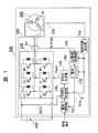
図1は、本発明によるインバータ装置100を有するモータ装置500の構成を示すブロック図である。モータ装置500は、モータ300とインバータ装置100を有している。モータ装置500は、モータ300の回転位置センサの取付位置誤差を検出して、モータ駆動の際に補正することでモータ300を高効率に駆動する用途に適したものである。
FIG. 1 is a block diagram showing a configuration of a
インバータ装置100は、電流検出部180、電流制御部120、PWM制御部145、PWM生成器140、インバータ回路110、および回転位置検出部130を有している。バッテリ200は、インバータ装置100の直流電圧源であり、バッテリ200の直流電圧DCVは、インバータ装置100のインバータ回路110によって可変電圧、可変周波数の3相交流に変換され、モータ300に印加される。
The
モータ300は、3相交流の供給により回転駆動される同期モータである。モータ300には、モータ300の誘起電圧の位相に合わせて3相交流の印加電圧の位相を制御するために回転位置センサ320が取り付けられており、回転位置検出部130にて回転位置センサ320の入力信号から検出位置θsを演算する。ここで、回転位置センサには、鉄心と巻線とから構成されるレゾルバがより好適であるが、GMRセンサや、ホール素子を用いたセンサを用いることができる。
The
インバータ装置100は、モータ300の出力を制御するための電流制御機能を有している。電流検出部160は、3相のモータ電流を電流センサIctで検出し、3相の電流検出値(Iu,Iv,Iw)と回転位置θとからdq変換したdq電流検出値(Id’,Iq’)を出力するdq電流変換器160と、dq電流検出値(Id’,Iq’)を平滑して電流検出値(Id,Iq)を出力する電流フィルタ170とを有する。電流制御器120は、電流検出値(Id,Iq)と、入力された電流指令値(Id*,Iq*)とが一致するように電圧指令(Vd*,Vq*)を出力する。
The
PWM制御器145では、電圧指令(Vd*,Vq*)を回転角度θに基づき2相/3相変換し、第三高調波を重畳した3相電圧指令(Vu*,Vv*、Vw*)を生成すると共に、ゼロクロス付近では変調波を直線近似してパルス幅変調(PWM)を行う。PWM制御器145の出力は、PWM生成器140にてパルス信号に変換され、ドライブ信号PWMとしてインバータ回路110に出力される。インバータ回路110の半導体スイッチ素子はドライブ信号PWMによりオン/オフ制御され、インバータ回路110の出力電圧が調整される。
なお、モータ装置500において、モータ300の回転速度を制御する場合には、モータ回転速度ωrを回転位置θの時間変化により演算し、上位制御器からの速度指令と一致するように電圧指令あるいは電流指令を作成する。また、モータ出力トルクを制御する場合には、モータ電流(Id,Iq)とモータトルクの関係式あるいはマップを用いて、電流指令(Id*、Iq*)を作成する。
In the
In the
次に、図2を用いて、一実施形態における変調波を示す波形図について説明する。
図2(a)は変調信号波形とキャリア信号波形を示し、変調率が比較的低い変調信号(変調波1)と、正弦波変調できる最大の変調波(変調波2)と、正弦波変調から100%パルスが連続した(飽和区間)状態となる過変調の状態になる変調波(変調波3)と、インバータ出力が最大となる矩形波状態となる変調波(変調波4)、および変調波信号と大小比較してPWMパルスを生成するキャリア信号とを示している。図2(b)は、変調波1のときのPWMパルス信号を示し、図2(c)は、変調波3のPWMパルス信号を示す。電気角度0〜180度のほぼ100%の区間でPWMパルスが連続してオンである。図2(d)は、変調波4のPWMパルス信号を示し、このPWMパルス信号は、電気角度0〜180度全区間でオンである。
Next, a waveform diagram showing a modulated wave in an embodiment will be described with reference to FIG.
FIG. 2A shows a modulation signal waveform and a carrier signal waveform. From a modulation signal (modulation wave 1) having a relatively low modulation rate, a maximum modulation wave (modulation wave 2) that can be sinusoidally modulated, and sine wave modulation. A modulation wave (modulation wave 3) that becomes an overmodulation state in which 100% pulses are continuous (saturation interval), a modulation wave (modulation wave 4) that becomes a rectangular wave state that maximizes the inverter output, and a modulation wave A carrier signal for generating a PWM pulse by comparing with a signal is shown. FIG. 2B shows a PWM pulse signal for the modulated
それぞれの変調波は、3相電圧指令(Vuc,Vvc、Vwc)の1相分の変調波H(θ)と等価であり、デッドタイムを無視すればU相の変調波Hu(θ)=Vuc/(DCV/2)にほぼ等しい。インバータ出力が飽和しない変調率=1となる時の正弦波の実効値を1とすれば、第3高調波を重畳した変調波H(θ)に含まれる基本波成分は1.15倍(115%)である(変調波2)。すなわち、電圧指令が1.15まではインバータ出力は飽和しない。
図2に示すように、第三高調波を重畳させた変調波H(θ)は、ゼロクロス付近で直線近似することができる。本実施形態では、変調波のゼロクロス付近では後述するような非同期PWM変調によりPWMパルスを生成し、それ以外の区間では、従来から採用されている非同期PWM変調によりPWMパルスを生成する。
なお、変調波のゼロクロスを中心に電気角度で±30度の角度区間を直線近似するのが好ましい。
Each modulation wave is equivalent to the modulation wave H (θ) for one phase of the three-phase voltage command (Vuc, Vvc, Vwc). If the dead time is ignored, the U-phase modulation wave Hu (θ) = Vuc / (DCV / 2) is approximately equal. If the effective value of the sine wave when the modulation factor = 1 at which the inverter output is not saturated is 1, the fundamental wave component included in the modulation wave H (θ) on which the third harmonic is superimposed is 1.15 times (115 %) (Modulated wave 2). That is, the inverter output is not saturated until the voltage command is 1.15.
As shown in FIG. 2, the modulated wave H (θ) on which the third harmonic is superimposed can be linearly approximated near the zero cross. In the present embodiment, a PWM pulse is generated by asynchronous PWM modulation as will be described later near the zero cross of the modulated wave, and a PWM pulse is generated by asynchronous PWM modulation conventionally employed in other sections.
Note that it is preferable to linearly approximate an angle interval of ± 30 degrees in electrical angle with the zero cross of the modulated wave as the center.
また、ゼロクロス付近の直線近似できる区間の変調波の傾きAは、電圧指令値に応じた変調率に比例し、変調波は角度位置θに比例する。例えば、ゼロクロス付近の角度をθ’とし、θ’を−30≦θ’≦30とすると、ゼロクロス付近の変調波H(θ’)は式(1)で表すことができる。
H(θ’)=A・θ’ (1)
In addition, the slope A of the modulated wave in the interval that can be linearly approximated near the zero cross is proportional to the modulation rate according to the voltage command value, and the modulated wave is proportional to the angular position θ. For example, assuming that the angle near the zero cross is θ ′ and θ ′ is −30 ≦ θ ′ ≦ 30, the modulated wave H (θ ′) near the zero cross can be expressed by Equation (1).
H (θ ′) = A · θ ′ (1)
すなわち、ゼロクロス付近の変調波H(θ)は、変調率の代わりに変調波の傾きAを用いて表すことができるので、ゼロクロス付近のインバータ出力パルス、すなわちPWMパルスは、変調波の傾きAから決定することができる。本実施形態では、後述するようにPWMパルス生成部は、変調波の傾きAとPWMパルスを対応付けたテーブルを有し、演算された変調波の傾きによりテーブルを参照してPWMパルスを生成する。
ここで、上記テーブルには、変調波の傾きAとPWMパルスのONタイミングとOFFタイミングが対応づけられている。
なお、|H(θ)|<|A・θ|となる条件では、変調波H(θ)の値を用いてインバータ出力パルスを決定すれば良い。
That is, since the modulation wave H (θ) near the zero cross can be expressed by using the slope A of the modulation wave instead of the modulation rate, the inverter output pulse near the zero cross, that is, the PWM pulse, is derived from the slope A of the modulation wave. Can be determined. In this embodiment, as will be described later, the PWM pulse generation unit has a table in which the modulation wave gradient A and the PWM pulse are associated with each other, and generates a PWM pulse by referring to the table based on the calculated modulation wave gradient. .
Here, in the table, the slope A of the modulation wave and the ON timing and OFF timing of the PWM pulse are associated with each other.
Note that, under the condition of | H (θ) | <| A · θ |, the inverter output pulse may be determined using the value of the modulated wave H (θ).
次に、図3を用いて、一実施形態におけるゼロクロス付近のPWMを示す波形図について説明する。
図3(A)は、変調波と三角波キャリアとの位相関係から、三角波キャリアの前半、すなわち三角波キャリア信号の立ち上がり区間にPWMパルスがオンとなる場合を示す。図3(A)の信号波形をゼロクロス・タイミング1の信号波形と呼ぶ。図3(B)は、変調波と三角波キャリアとの位相関係から、三角波キャリアの後半、すなわち三角波キャリア信号の立ち下がり区間にPWMパルスがオンとなる場合を示している。図3(B)の信号波形をゼロクロス・タイミング2の信号波形と呼ぶ。
図3(A)、(B)ともに、モータが一定速度で回転しているときの一例であり、一定のPWMキャリア周期の間にモータが回転した時の角度変化幅Δθがほぼ一定であり、この角度変化幅△θがキャリア周期と同等である。また、変調波をゼロクロス近傍で直線近似した区間において、PWMパルスが2〜3パルス発生する場合を示す。
Next, a waveform diagram showing PWM near the zero cross in one embodiment will be described with reference to FIG.
FIG. 3A shows a case where the PWM pulse is turned on in the first half of the triangular wave carrier, that is, in the rising section of the triangular wave carrier signal, from the phase relationship between the modulated wave and the triangular wave carrier. The signal waveform in FIG. 3A is referred to as a zero-crossing
3 (A) and 3 (B) are examples when the motor is rotating at a constant speed, and the angle change width Δθ when the motor rotates during a constant PWM carrier cycle is substantially constant, This angle change width Δθ is equal to the carrier period. In addition, a case where two to three PWM pulses are generated in a section in which a modulation wave is linearly approximated near the zero cross is shown.
図3(A),(B)において、(a)は変調波と三角波キャリア信号を示し、(b)は1PWM周期で出力すべきPWMパルスを示し、(c)は、マイコンを使ってPWMパルスを生成する場合のPWMタイマ値を示し、この実施形態では、鋸波状のPWMタイマを示している。 3A and 3B, (a) shows a modulated wave and a triangular wave carrier signal, (b) shows a PWM pulse to be output in one PWM cycle, and (c) shows a PWM pulse using a microcomputer. In this embodiment, a sawtooth PWM timer is shown.
図3(A)のゼロクロス・タイミング1の信号波形は、上述したように、三角波キャリア信号の立ち上がり区間にPWMパルスがオンとなる場合であり、角度位置θrのタイミングからΔθ/2以上離れた角度位置θaで変調波が過変調レベル1に達する場合を示している。ゼロクロス・タイミング1の信号波形では、角度位置θr+Δθのタイミング以降でPWMパルスを区間θ2だけHighにする。その後、変調波H(θ)がゼロになる角度θcまでLowパルスを出力する。そして、角度θcのタイミングでPWMパルスをHighにし、角度θc以降にPWMパルスを区間θ5だけLowパルスを出力する。その後、変調波は角度θbのタイミングで過変調レベル2に達する。
As described above, the signal waveform of zero
従来、特許文献1〜3に開示されているように、交流出力の1/2周期で変化する正側の電圧積分(正側電圧)と負側の電圧積分(負側電圧)のアンバランスを解消するため、出力電圧のゼロクロス付近におけるPWMパルスをこの区間以外の生成方式と変更している。
特許文献1では、インバータの出力電圧のゼロクロス付近をduty50%にして出力電圧誤差を最小限にしている。また、特許文献2では、インバータの出力電圧のゼロクロス近傍で変調波の傾きが急峻の場合に、変調率を抑制した変調波によってPWMパルスを発生させることにより位相誤差を低減している。したがって、これら2つの文献の従来技術ではインバータ出力が低下してしまう。
そこで、本発明の一実施形態では、変調波がゼロクロスする電気角度の前後の電気角度範囲、たとえば、±30度範囲では、−30度範囲での正側の出力電圧と、+30度範囲での負側の出力電圧が等しくなるようにして、±30度の電気角度範囲での出力低下を抑制する。
図3(A),(B)において、θ2=θ5とすれば、変調波のゼロクロスを中心に負側電圧と正側電圧の大きさを平衡にできる。また、変調波のゼロクロス付近において、θc−θa=θb−θcに調整してパルスエッジを発生できるため、インバータ出力の位相誤差を低減できる。更に、PWMパルスは変調波に応じた大きさを正確に発生できるため、インバータ出力の低下も防止できる。
Conventionally, as disclosed in
In
Therefore, in one embodiment of the present invention, in the electrical angle range before and after the electrical angle at which the modulated wave zero-crosses, for example, in the range of ± 30 degrees, the output voltage on the positive side in the range of −30 degrees and the range of +30 degrees The negative output voltage is made equal to suppress the output drop in the electrical angle range of ± 30 degrees.
3A and 3B, if θ2 = θ5, the magnitudes of the negative side voltage and the positive side voltage can be balanced around the zero cross of the modulated wave. Further, since the pulse edge can be generated by adjusting to θc−θa = θb−θc in the vicinity of the zero cross of the modulated wave, the phase error of the inverter output can be reduced. Furthermore, since the PWM pulse can accurately generate a magnitude corresponding to the modulation wave, it is possible to prevent a decrease in the inverter output.
ここで、インバータ装置が出力すべきPWMパルス幅について、変調波のゼロクロス点の回転角度θcから過変調レベル2に達する回転角度θbの区間を用いて説明する。変調波を規格化して−1(過変調レベル1)から+1(過変調レベル2)とした場合、回転角度θcの規格化値=0から回転角度θbの規格化値=1との変調波の面積は、1/2になる。一方、規格化した変調波−1〜+1の区間(回転角度θa〜θb)で出力できるOnDutyを100%とすると、規格化した変調波0〜1の区間(回転角度θc〜θb)でのOnDutyは50〜100%(Δ50%)に相当する。すなわち、図3(A)における回転角度θc〜θbの区間平均OnDutyは75%になり、回転角度θc〜θbの区間でPWMパルスの1.5パルス分で、OnDuty=75%となるように、θ4、θ5、θ6を決定する。θ4とθ6はOnDutyであるので、好ましくは、θ5=25%のOffDutyを設定すればよい。また、回転角度θa〜θcの区間は同様に、θ1とθ3はOffDutyを設定し、θ2にOnDuty=25%を設定すればよい。
このように、PWMパルス生成器140は、出力電圧のゼロクロス点θcを中心に直線近似した角度区間θa〜θbにおいて、PWMパルスのオンパルスとオフパルスの面積を積分した値が等しくなるようにPWMパルスを生成する。
Here, the PWM pulse width to be output by the inverter device will be described using a section of the rotation angle θb reaching the overmodulation level 2 from the rotation angle θc of the zero cross point of the modulated wave. When the modulated wave is normalized from -1 (overmodulation level 1) to +1 (overmodulation level 2), the modulated wave with the normalized value of rotation angle θc = 0 to the normalized value of rotation angle θb = 1 The area becomes 1/2. On the other hand, when the OnDuty that can be output in the normalized modulated wave-1 to +1 interval (rotation angle θa to θb) is 100%, the OnDuty in the normalized modulated
As described above, the
図3(B)のゼロクロス・タイミング2の信号波形は、上述したように、三角波キャリア信号の立ち下がり区間にPWMパルスがオンとなる場合であり、角度位置θrのタイミングからΔθ/2以内の角度位置θaで変調波が過変調レベル1に達する場合を示している。ゼロクロス・タイミング2の信号波形では、角度位置θaで過変調レベル1と等しくなる。この点が図3(A)と異なる。したがって、変調波と三角波キャリアとの位相関係から三角波キャリアの後半、すなわち立ち下がりスロープ側でPWMパルスがHighになる点以外は図3(A)と同様である。
The signal waveform at zero cross timing 2 in FIG. 3B is a case where the PWM pulse is turned on in the falling section of the triangular wave carrier signal as described above, and an angle within Δθ / 2 from the timing of the angular position θr. The case where the modulated wave reaches the
本発明の一実施形態では、非同期PWMの周期内で変調波のゼロクロス付近でパルス幅が変化するようにPWMパルスを生成するため、PWMパルスのONパルス中心の時間間隔、またはOFFパルス中心の時間間隔が異なるように制御することになる。すなわち、PWMパルス生成部は、出力電圧のゼロクロス点を中心に直線近似した角度区間において、複数のPWMパルスのオンパルスの中心時間間隔と、オフパルスの中心時間間隔がインバータ回路の運転状態、すなわち、モータ出力要求に基づいて異なるようにPWMパルスが生成される。 In one embodiment of the present invention, the PWM pulse is generated so that the pulse width changes in the vicinity of the zero cross of the modulated wave within the period of the asynchronous PWM, so that the time interval between the ON pulse centers of the PWM pulses or the time of the OFF pulse center The control is performed so that the intervals are different. That is, the PWM pulse generator is configured such that the central time interval of the on-pulses of the plurality of PWM pulses and the central time interval of the off-pulses are the operating state of the inverter circuit, i. PWM pulses are generated differently based on output requirements.
ここで、図3では、1相分のPWMパルスを示しているが、過変調モードにある場合の他の2相は過変調レベル1あるいは過変調レベル2の状態にある。
Here, FIG. 3 shows a PWM pulse for one phase, but the other two phases in the overmodulation mode are in the
なお、図3では、PWMパルスの立ち上がりエッジおよび立ち下がりエッジをPWMキャリア周期のタイミングに同期させた場合を示している。しかし、PWMパルスの立ち上がりエッジおよび立ち下がりエッジを、PWMキャリア周期のタイミングに一致させなくても良く、角度θcを基準に出力電圧の波形を対称波形とすること望ましい。また、モータが一定速度で回転している場合について説明したが、モータが加減速している場合には、加速度あるいは減速度を考慮してΔθを演算すれば、同様のロジックにてPWMパルスが作成できる。 FIG. 3 shows a case where the rising edge and falling edge of the PWM pulse are synchronized with the timing of the PWM carrier cycle. However, the rising edge and falling edge of the PWM pulse do not have to coincide with the timing of the PWM carrier cycle, and it is desirable to make the waveform of the output voltage symmetrical with respect to the angle θc. In addition, although the case where the motor is rotating at a constant speed has been described, when the motor is accelerating / decelerating, if Δθ is calculated in consideration of acceleration or deceleration, the PWM pulse is generated with the same logic. Can be created.
次に、図4を用いて、一実施形態におけるパルス生成を示す波形図について説明する。 図4の(a)は変調波信号を示し、(b)は鋸波状のタイマカウンタのU相分の動作を示し、(c)はU相のPWMパルスを示し、(d)は正弦波変調時のV相PWMパルスと、U−V間の線間電圧相当のPWMパルスを示す。(e)は可変調時のV相PWMパルスと、U−V間の線間電圧相当のPWMパルスを示す。 Next, a waveform diagram showing pulse generation in an embodiment will be described with reference to FIG. 4A shows the modulated wave signal, FIG. 4B shows the operation of the sawtooth timer counter for the U phase, FIG. 4C shows the U phase PWM pulse, and FIG. 4D shows the sinusoidal modulation. The V-phase PWM pulse at the time and the PWM pulse corresponding to the line voltage between U and V are shown. (E) shows a V-phase PWM pulse at the time of modulation and a PWM pulse corresponding to a line voltage between U and V.
図4(b)において、PWMキャリアの中心でPWMパルスを生成する場合、タイマ周期の中心にパルス幅Pu1を作成するように、タイマ中心値を中心にタイマ比較値Vu1とVu2を設定し、図4(c)のインバータ出力パルスVuを出力する。モータに印加される電圧パルスは図4(d)のVu−vになる。図3に示したタイミングでPWMパルスを出力する場合、すなわち、ゼロクロス付近の正側出力電圧と負側出力電圧を均等にするようにPWMパルスのONタイミングとOFFタイミングを決定する場合、パルス幅Pu1のままタイミングをシフトするようにタイマ比較値Vu1’とVu2’を設定し、図4(c)のインバータ出力パルスVu’を出力することができる。これにより、U相PWMパルスは、図4(a)の変調波のゼロクロス点θcに同期したパルスとなるが、正弦波変調においてモータに印加できるパルスは、図4(d)のVu’−vに示すPWMパルスとなる。このため、PWMパルスによる電圧誤差を含むことになるものの、正弦波変調においては一般にモータ回転速度(インバータの出力周波数)が低いため、PWMパルス数は多く、電圧誤差の影響は小さい。好ましくは、モータ回転速度が低い場合にパルスシフトを停止する。 In FIG. 4B, when generating a PWM pulse at the center of the PWM carrier, the timer comparison values Vu1 and Vu2 are set around the timer center value so that the pulse width Pu1 is created at the center of the timer period. The inverter output pulse Vu of 4 (c) is output. The voltage pulse applied to the motor is Vu-v in FIG. When the PWM pulse is output at the timing shown in FIG. 3, that is, when the ON timing and the OFF timing of the PWM pulse are determined so as to equalize the positive side output voltage and the negative side output voltage near the zero cross, the pulse width Pu1 The timer comparison values Vu1 ′ and Vu2 ′ are set so that the timing is shifted as it is, and the inverter output pulse Vu ′ of FIG. 4C can be output. As a result, the U-phase PWM pulse becomes a pulse synchronized with the zero-cross point θc of the modulated wave in FIG. 4A, but the pulse that can be applied to the motor in the sine wave modulation is Vu′-v in FIG. The PWM pulse shown in FIG. For this reason, although a voltage error due to the PWM pulse is included, since the motor rotation speed (output frequency of the inverter) is generally low in sine wave modulation, the number of PWM pulses is large and the influence of the voltage error is small. Preferably, the pulse shift is stopped when the motor rotation speed is low.
過変調においては、一般にインバータ出力周波数が高く、PWMパルス数が少ないため電圧誤差の影響は大きくなる。図4(e)に示すVv”は過変調時のV相信号で、U相ゼロクロス付近においてほぼDuty100%であり、U相をパルスシフトしていない時のVu−v”はU相変調波のゼロクロスに同期したPWMパルスになっていない。U相をパルスシフトしたときのVu’−v”は、U相PWMパルスがそのまま出力され、変調波のゼロクロスに同期したインバータ出力が得られる。 In overmodulation, the inverter output frequency is generally high and the number of PWM pulses is small, so that the influence of the voltage error becomes large. Vv ″ shown in FIG. 4 (e) is a V-phase signal at the time of overmodulation, and is nearly 100% Duty near the U-phase zero cross, and Vu−v ″ when the U-phase is not pulse-shifted is a U-phase modulated wave. The PWM pulse is not synchronized with the zero cross. As for Vu'-v "when the U phase is pulse-shifted, the U phase PWM pulse is output as it is, and an inverter output synchronized with the zero cross of the modulated wave is obtained.
以上説明したインバータ装置100は、モータ出力要求に基づいて、すなわち、インバータ運転状態に基づいて、直流電圧を交流電圧に変換するためのPWMパルスを生成するため、電流制御器120、PWM制御器145、およびPWM生成器140から構成されるPWMパルス生成部と、PWMパルス生成部で生成されたPWMパルスにより直流電圧を交流電圧に変換してモータを駆動するインバータ回路110とを備える。PWMパルス生成部は、出力電圧のゼロクロス点を中心に直線近似した角度区間において複数のPWMパルスのオンパルスの中心時間間隔、およびオフパルスの中心時間間隔のいずれか一方を、モータ出力要求に基づいて変化させてPWMパルスを生成する。PWMパルス生成部は、モータ出力要求に応じてモータが所定トルクと所定回転速度で駆動されるようにPWMパルスを生成する。
以上説明した実施形態では、インバータ運転状態に応じてタイマ比較値Vu1とVu2をシフトさせることにより所望のPWMパルスを生成することができる。この方式以外でPWMパルスを生成してもよい。
The
In the embodiment described above, a desired PWM pulse can be generated by shifting the timer comparison values Vu1 and Vu2 according to the inverter operating state. You may generate | occur | produce a PWM pulse other than this system.
本発明の一実施形態では、PWMキャリア周期内で任意のタイミングにパルスシフトして、変調波のゼロクロス付近のPWMパルスタイミングを調整することができるため、非同期PWM制御においてもインバータ出力電圧(位相含む)誤差の影響を低減したインバータ出力が得られる。また、同期PWM制御に比べてマイコン負荷の増大を抑制することができるといった効果がある。 In one embodiment of the present invention, the PWM pulse timing in the vicinity of the zero cross of the modulated wave can be adjusted by pulse-shifting to an arbitrary timing within the PWM carrier cycle, so that the inverter output voltage (including phase) is also included in asynchronous PWM control. ) Inverter output with reduced influence of error can be obtained. Further, there is an effect that an increase in the microcomputer load can be suppressed as compared with the synchronous PWM control.
PWMパルス生成器140は、変調波の傾きとPWMパルスを対応付けたテーブルを有し、演算された変調波の傾きによりテーブルを参照してPWMパルスを生成するようにしたが、テーブルを使用せずに傾きAからPWMパルスを決定してもよい。また、傾きAを用いることなくPWMパルスを生成してもよい。また、PWMパルス生成器140は、出力電圧のゼロクロス点を中心に直線近似した角度区間において、複数のPWMパルスのオンパルスとオフパルスの面積を積分した値が等しくなるようにPWMパルスを生成することが好ましい。
The
次に、図5を用いて、本発明の一実施形態に示したモータ駆動装置を適用した電動パワーステアリング装置の構成について説明する。 Next, the configuration of an electric power steering apparatus to which the motor driving apparatus shown in one embodiment of the present invention is applied will be described with reference to FIG.
図5は、本発明の一実施形態に示したモータ駆動装置を適用した電動パワーステアリング装置の構成図である。 FIG. 5 is a configuration diagram of an electric power steering apparatus to which the motor driving apparatus shown in the embodiment of the present invention is applied.
電動パワーステアリングの電動アクチュエータは、図5に示すように、トルク伝達機構902と、モータ300と、インバータ装置100とから構成される。電動パワーステアリング装置は、電動アクチュエータと、ハンドル(ステアリング)900と、操舵検出器901および操作量指令器903を備え、運転者が操舵するハンドル900の操作力は電動アクチュエータを用いてトルクアシストする構成を有する。
As shown in FIG. 5, the electric actuator of the electric power steering includes a torque transmission mechanism 902, a
電動アクチュエータのトルク指令τ*は、ハンドル900の操舵アシストトルク指令として操作量指令器903にて作成される。トルク指令τ*により駆動される電動アクチュエータの出力を用いて運転者の操舵力が軽減される。インバータ装置100は、入力指令としてトルク指令τ*を受け、モータ300のトルク定数とトルク指令τ*とからトルク指令値に追従するようにモータ電流を制御する。
The torque command τ * of the electric actuator is created by the operation
モータ300のロータに直結された出力軸から出力されるモータ出力τmはウォーム、ホイールや遊星ギヤなどの減速機構あるいは油圧機構を用いたトルク伝達機構902を介し、ステアリング装置のラック910にトルクを伝達する。ラック910に伝達されたトルクにより、運転者のハンドル900の操舵力(操作力)が電動力にて軽減(アシスト)され、車輪920,921の操舵角が操作される。
The motor output τm output from the output shaft directly connected to the rotor of the
このアシスト量は次のようにして決定される。すなわち、ステアリングシャフトに組み込まれた操舵検出器901により操舵角や操舵トルクが検出され、車両速度や路面状態などの状態量を加味して操作量指令器903によりトルク指令τ*が算出される。
This assist amount is determined as follows. That is, a steering angle and a steering torque are detected by a
本発明の一実施形態によるインバータ装置100は、高速回転した場合にもインバータ出力電圧の平均化により、低振動・低騒音化できる利点がある。
The
図6は、本発明によるインバータ装置100が適用された電動車両600を示す図である。電動車両600は、モータ300をモータ/ジェネレータとして適用したパワートレインを有する。
FIG. 6 is a diagram showing an
電動車両600のフロント部には、前輪車軸601が回転可能に軸支されており、前輪車軸601の両端には、前輪602,603が設けられている。電動車両600のリア部には、後輪車軸604が回転可能に軸支されており、後輪車軸604の両端には後輪605,606が設けられている。
A
前輪車軸601の中央部には、動力分配機構であるデファレンシャルギア611が設けられており、エンジン610から変速機612を介して伝達された回転駆動力を左右の前輪車軸601に分配するようになっている。エンジン610とモータ300とは、エンジン610のクランクシャフトに設けられたとモータ300の回転軸に設けられたプーリーの間に架け渡されたベルトを介して機械的に連結されている。
A
これにより、モータ300の回転駆動力がエンジン610に、エンジン610の回転駆動力がモータ300にそれぞれ伝達できるようになっている。モータ300は、インバータ装置100によって制御された3相交流電力がステータのステータコイルに供給されることによって、ロータが回転し、3相交流電力に応じた回転駆動力を発生する。
Thereby, the rotational driving force of the
すなわち、モータ300は、インバータ装置100によって制御されて電動機として動作する一方、エンジン610の回転駆動力を受けてロータが回転することによって、3相交流電力を発生する発電機として動作する。
That is, the
インバータ装置100は、高電圧(42Vあるいは300V)系電源である高圧バッテリ622から供給された直流電力を3相交流電力に変換する電力変換装置であり、運転指令値とロータの磁極位置とに基づいて、モータ300のステータコイルに流れる3相交流電流を制御する。
The
モータ300によって発電された3相交流電力は、インバータ装置100によって直流電力に変換されて高圧バッテリ622を充電する。高圧バッテリ622にはDC−DCコンバータ624を介して低圧バッテリ623に電気的に接続されている。低圧バッテリ623は、電動車両600の低電圧(14v)系電源を構成するものであり、エンジン610を初期始動(コールド始動)させるスタータ625,ラジオ,ライトなどの電源に用いられている。
The three-phase AC power generated by the
電動車両600が信号待ちなどの停車時(アイドルストップモード)にあるとき、エンジン610を停止させ、再発車時にエンジン610を再始動(ホット始動)させる時には、インバータ装置100でモータ300を駆動し、エンジン610を再始動させる。
When the
なお、アイドルストップモードにおいて、高圧バッテリ622の充電量が不足している場合や、エンジン610が十分に温まっていない場合などにおいては、エンジン610を停止せず駆動を継続する。また、アイドルストップモード中においては、エアコンのコンプレッサなど、エンジン610を駆動源としている補機類の駆動源を確保する必要がある。この場合、モータ300を駆動させて補機類を駆動する。
In the idle stop mode, when the charge amount of the
加速モード時や高負荷運転モードにある時にも、モータ300を駆動させてエンジン610の駆動をアシストする。逆に、高圧バッテリ622の充電が必要な充電モードにある時には、エンジン610によってモータ300を発電させて高圧バッテリ622を充電する。すなわち、モータ300は、電動車両600の制動時や減速時などでは回生運転される。
The
電動車両600は、モータ出力要求に基づいて、直流電圧を交流電圧に変換するためのPWMパルスを生成し、生成されたPWMパルスにより直流電圧を交流電圧に変換してモータを駆動するインバータ装置100と、直流電圧を昇圧するDC/DCコンバータ624とを備えている。インバータ装置100は、出力電圧のゼロクロス点を中心に直線近似した角度区間において複数のPWMパルスのオンパルスの中心時間間隔、およびオフパルスの中心時間間隔のいずれか一方をDC/DCコンバータの出力電圧に基づいて変化させてPWMパルスを生成する。
The
本発明によるインバータ駆動装置を用いた電動車両では、直流電圧を制御するDC/DCコンバータ624の出力電圧に応じて、インバータ出力電圧のゼロクロス点(図3に示すθcに相当)を中心に直線近似した角度区間(図3に示すθa〜θbに相当)のPWMパルスのONパルス中心の時間間隔、またはOFFパルス中心の時間間隔を変化させることにより、電動車両600のDC/DCコンバータ624の出力電圧を調整してインバータ装置100の出力範囲を拡大する制御を安定的に行うことができる。
In the electric vehicle using the inverter drive device according to the present invention, linear approximation is performed around the zero cross point of the inverter output voltage (corresponding to θc shown in FIG. 3) according to the output voltage of the DC /
以上説明した本発明によるインバータ装置によれば、以下のような作用効果を奏する。
(1)本発明のインバータ装置100は、モータ出力要求に基づいて、直流電圧を交流電圧に変換するためのPWMパルスを生成するPWMパルス生成器140と、PWMパルス生成器140で生成されたPWMパルスにより直流電圧を交流電圧に変換してモータ300を駆動するインバータ回路110とを備え、PWMパルス生成器140は、出力電圧のゼロクロス点を中心に直線近似した角度区間において複数のPWMパルスのオンパルスの中心時間間隔、およびオフパルスの中心時間間隔のいずれか一方をモータ出力要求に基づいて変化させてPWMパルスを生成するようにした。すなわち、上記直線近似区間では正側、負側の出力電圧を均一化するようにPWMパルスを生成するようにした。これにより、インバータ装置100の運転状態によって生じる出力電圧の大きさと位相の誤差をキャンセルできる。
The inverter device according to the present invention described above has the following operational effects.
(1) The
(2)本発明のインバータ装置100は、モータ出力要求に基づいて、直流電圧を交流電圧に変換するためのPWMパルスを生成するPWMパルス生成器140と、PWMパルス生成器140で生成されたPWMパルスにより直流電圧を交流電圧に変換してモータ300を駆動するインバータ回路110とを備え、PWMパルス生成器140は、出力電圧のゼロクロス点を中心に直線近似した角度区間において、複数のPWMパルスのオンパルスの中心時間間隔とオフパルスの中心時間間隔がモータ出力要求に基づいて異なるようにPWMパルスを生成するようにした。すなわち、モータ出力要求に応じてインバータ回路のスイッチング周波数が変動しても、インバータ装置100の運転状態によって生じるPWMキャリア周期を可変することなくインバータ出力電圧の電圧パルスタイミング誤差をキャンセルできる。
(2) The
(3)本発明のインバータ装置100は、角度区間θa〜θbが出力電圧のゼロクロス点θcを基準として少なくとも電気角で±30度の範囲を含む区間であるようにした。これにより、変調波の直線近似が容易になるため制御プログラムが簡単に構成できる。
(3) In the
(4)本発明のインバータ装置100において、PWMパルス生成器140は、モータ出力要求に応じてモータ300が所定トルクと所定回転速度で駆動されるようにPWMパルスを生成するようにした。これにより、インバータ装置100の運転状態によらず安定したインバータ出力ができる。
(4) In the
(5)本発明のインバータ装置100において、PWMパルス生成器140は、出力電圧のゼロクロス点θcを基準として少なくとも電気角で±30度の範囲を含む角度区間θa〜θbでの変調波H(θ’)=A・θ’の傾きAを演算し、演算された傾きAによりPWMパルスを生成するようにした。これにより、ゼロクロス点θc付近の最適なPWMパルスのシフトタイミングを演算により容易に求めることができる。
(5) In the
(6)本発明のインバータ装置100において、PWMパルス生成器140は、変調波H(θ’)=A・θ’の傾きAとPWMパルスを対応付けたテーブルを有し、演算された変調波H(θ’)=A・θ’の傾きAによりテーブルを参照してPWMパルスを生成する。これにより、インバータ装置100の出力が飽和する過変調領域の線形化が可能になるため、制御動作を安定させることができる。
(6) In the
(7)本発明のインバータ装置100において、PWMパルス生成器140は、出力電圧のゼロクロス点θcを中心に直線近似した角度区間θa〜θbにおいて、複数のPWMパルスのオンパルスとオフパルスの面積を積分した値が等しくなるようにPWMパルスを生成するようにした。これにより、モータ300の回転を安定させることができる。
(7) In the
(8)本発明の電動車両600は、モータ出力要求に基づいて、直流電圧を交流電圧に変換するためのPWMパルスを生成するPWMパルス生成器140と、PWMパルス生成器140で生成されたPWMパルスにより直流電圧を交流電圧に変換してモータ300を駆動するインバータ回路110とを有するインバータ装置100と、直流電圧を昇圧するDC/DCコンバータ624とを備え、PWMパルス生成器140は、出力電圧のゼロクロス点θcを中心に直線近似した角度区間θa〜θbにおいて複数のPWMパルスのオンパルスの中心時間間隔、およびオフパルスの中心時間間隔のいずれか一方をDC/DCコンバータ624の出力電圧に基づいて変化させてPWMパルスを生成するようにした。これにより、電動車両600のDC/DCコンバータ624の出力電圧を調整してインバータ装置100の出力範囲を拡大する制御を安定的に行うことができる。
(8) The
一実施形態の電動車両600はハイブリッド自動車である場合について説明したが、プラグインハイブリッド自動車、電気自動車などの場合においても同様な効果が得られる。
Although the case where the
また、上述の実施形態では、インバータ装置単体について説明したが、当該上述の機能を有していれば、インバータ装置とモータとが一体化したモータ駆動システムにも本発明を適用できる。 Further, in the above-described embodiment, the single inverter device has been described. However, the present invention can be applied to a motor drive system in which the inverter device and the motor are integrated as long as the inverter device has the above-described function.
なお、本発明は、上述の実施の形態に限定されるものではなく、本発明の趣旨を逸脱しない範囲で種々の変更が可能である。 Note that the present invention is not limited to the above-described embodiment, and various modifications can be made without departing from the spirit of the present invention.
100…インバータ装置
120…電流制御部
160…電流検出部
110…インバータ回路
130…回転位置検出部
200…バッテリ
500…モータ装置
300…モータ
320…回転位置センサ
600…電動車両
DESCRIPTION OF
Claims (8)
前記PWMパルス生成部で生成されたPWMパルスにより直流電圧を交流電圧に変換してモータを駆動するインバータ回路とを備え、
前記PWMパルス生成部は、出力電圧のゼロクロス点を中心に直線近似した角度区間において複数のPWMパルスのオンパルスの中心時間間隔、およびオフパルスの中心時間間隔のいずれか一方を前記モータ出力要求に基づいて変化させてPWMパルスを生成するインバータ装置。 A PWM pulse generator that generates a PWM pulse for converting a DC voltage into an AC voltage based on a motor output request;
An inverter circuit for driving a motor by converting a DC voltage into an AC voltage by the PWM pulse generated by the PWM pulse generator;
The PWM pulse generation unit determines one of a central time interval of on-pulses of a plurality of PWM pulses and a central time interval of off-pulses based on the motor output request in an angle interval linearly approximated around a zero cross point of an output voltage. An inverter device that generates PWM pulses by changing them.
前記PWMパルス生成部で生成されたPWMパルスにより直流電圧を交流電圧に変換してモータを駆動するインバータ回路とを備え、
前記PWMパルス生成部は、出力電圧のゼロクロス点を中心に直線近似した角度区間において、複数のPWMパルスのオンパルスの中心時間間隔とオフパルスの中心時間間隔が前記モータ出力要求に基づいて異なるようにPWMパルスを生成するインバータ装置。 A PWM pulse generator that generates a PWM pulse for converting a DC voltage into an AC voltage based on a motor output request;
An inverter circuit for driving a motor by converting a DC voltage into an AC voltage by the PWM pulse generated by the PWM pulse generator;
The PWM pulse generator generates a PWM signal so that a central time interval of on-pulses and a central time interval of off-pulses of a plurality of PWM pulses are different based on the motor output request in an angular interval that is linearly approximated around a zero cross point of an output voltage. An inverter device that generates pulses.
前記角度区間は、前記出力電圧の前記ゼロクロス点を基準として少なくとも電気角で±30度の範囲を含む区間であるインバータ装置。 In the inverter device according to claim 1 or 2,
The said angle area is an inverter apparatus which is an area including the range of at least +/- 30 degree | times by an electrical angle on the basis of the said zero cross point of the said output voltage.
前記PWMパルス生成部は、前記モータ出力要求に応じて前記モータが所定トルクと所定回転速度で駆動されるように前記PWMパルスを生成するインバータ装置。 In the inverter device according to claim 1 or 2,
The PWM pulse generation unit generates the PWM pulse so that the motor is driven at a predetermined torque and a predetermined rotation speed in response to the motor output request.
前記PWMパルス生成部は、前記出力電圧の前記ゼロクロス点を基準として少なくとも電気角で±30度の範囲を含む区間での変調波の傾きを演算し、前記演算された傾きにより前記PWMパルスを生成するインバータ装置。 In the inverter device according to claim 1 or 2,
The PWM pulse generation unit calculates a slope of a modulated wave in a section including a range of at least an electrical angle of ± 30 degrees with reference to the zero cross point of the output voltage, and generates the PWM pulse based on the calculated slope. Inverter device.
前記PWMパルス生成部は、前記変調波の傾きと前記PWMパルスを対応付けたテーブルを有し、前記変調波の傾きにより前記テーブルを参照して前記PWMパルスを生成するインバータ装置。 In the inverter device according to claim 5,
The PWM pulse generation unit has an table that associates the slope of the modulated wave with the PWM pulse, and generates the PWM pulse by referring to the table based on the slope of the modulated wave.
前記PWMパルス生成部は、前記出力電圧のゼロクロス点を中心に直線近似した角度区間において、複数のPWMパルスのオンパルスとオフパルスの面積を積分した値が等しくなるように前記PWMパルスを演算するインバータ装置。 In the inverter device according to claim 1 or 2,
The PWM pulse generation unit calculates the PWM pulse so that the integrated value of the on-pulse and off-pulse areas of a plurality of PWM pulses is equal in an angle section linearly approximated around the zero-cross point of the output voltage .
前記PWMパルス生成部で生成されたPWMパルスにより直流電圧を交流電圧に変換してモータを駆動するインバータ回路と、
前記直流電圧を昇圧するDC/DCコンバータとを備え、
前記PWMパルス生成部は、出力電圧のゼロクロス点を中心に直線近似した角度区間において複数のPWMパルスのオンパルスの中心時間間隔、およびオフパルスの中心時間間
隔のいずれか一方を前記DC/DCコンバータの出力電圧に基づいて変化させてPWMパルスを生成する電動車両。
A PWM pulse generator that generates a PWM pulse for converting a DC voltage into an AC voltage based on a motor output request;
An inverter circuit for driving a motor by converting a DC voltage into an AC voltage by the PWM pulse generated by the PWM pulse generator;
A DC / DC converter that boosts the DC voltage,
The PWM pulse generation unit outputs one of a central time interval of on-pulses of a plurality of PWM pulses and a central time interval of off-pulses in the angle section that is linearly approximated around the zero cross point of the output voltage. An electric vehicle that generates PWM pulses by changing the voltage.
Priority Applications (5)
| Application Number | Priority Date | Filing Date | Title |
|---|---|---|---|
| JP2013143787A JP6062327B2 (en) | 2013-07-09 | 2013-07-09 | Inverter device and electric vehicle |
| US14/902,352 US9819299B2 (en) | 2013-07-09 | 2014-05-21 | Inverter device and electric vehicle |
| EP14822715.0A EP3021477B1 (en) | 2013-07-09 | 2014-05-21 | Inverter device and electric vehicle |
| PCT/JP2014/063405 WO2015004994A1 (en) | 2013-07-09 | 2014-05-21 | Inverter device and electric vehicle |
| CN201480039232.6A CN105392660B (en) | 2013-07-09 | 2014-05-21 | DC-to-AC converter and electric vehicle |
Applications Claiming Priority (1)
| Application Number | Priority Date | Filing Date | Title |
|---|---|---|---|
| JP2013143787A JP6062327B2 (en) | 2013-07-09 | 2013-07-09 | Inverter device and electric vehicle |
Publications (3)
| Publication Number | Publication Date |
|---|---|
| JP2015019458A JP2015019458A (en) | 2015-01-29 |
| JP2015019458A5 JP2015019458A5 (en) | 2016-02-04 |
| JP6062327B2 true JP6062327B2 (en) | 2017-01-18 |
Family
ID=52279689
Family Applications (1)
| Application Number | Title | Priority Date | Filing Date |
|---|---|---|---|
| JP2013143787A Active JP6062327B2 (en) | 2013-07-09 | 2013-07-09 | Inverter device and electric vehicle |
Country Status (5)
| Country | Link |
|---|---|
| US (1) | US9819299B2 (en) |
| EP (1) | EP3021477B1 (en) |
| JP (1) | JP6062327B2 (en) |
| CN (1) | CN105392660B (en) |
| WO (1) | WO2015004994A1 (en) |
Cited By (1)
| Publication number | Priority date | Publication date | Assignee | Title |
|---|---|---|---|---|
| WO2020044890A1 (en) | 2018-08-30 | 2020-03-05 | 日立オートモティブシステムズ株式会社 | Inverter device |
Families Citing this family (14)
| Publication number | Priority date | Publication date | Assignee | Title |
|---|---|---|---|---|
| JP6260587B2 (en) * | 2015-06-29 | 2018-01-17 | トヨタ自動車株式会社 | Power supply |
| WO2018062083A1 (en) * | 2016-09-30 | 2018-04-05 | 日本電産トーソク株式会社 | Control device, control method, motor, and electric oil pump |
| JP6765985B2 (en) * | 2017-02-16 | 2020-10-07 | 日立オートモティブシステムズ株式会社 | Inverter device and electric vehicle |
| JP7016249B2 (en) | 2017-12-04 | 2022-02-04 | 日立Astemo株式会社 | Motor drive system |
| DE102017223156A1 (en) * | 2017-12-19 | 2019-06-19 | Robert Bosch Gmbh | Measuring PWM without distortion of the phase voltage |
| BR112020022425A2 (en) * | 2018-07-02 | 2021-02-09 | Nippon Steel Corporation | conveyor frequency adjustment method, motor drive system, and conveyor frequency adjustment device |
| TWI703792B (en) * | 2018-08-27 | 2020-09-01 | 飛宏科技股份有限公司 | Modulation method for inverter ac waveform |
| KR102602368B1 (en) * | 2018-10-24 | 2023-11-17 | 현대자동차주식회사 | Vehicle and method for controlling the vehicle |
| JP7163150B2 (en) * | 2018-11-28 | 2022-10-31 | 日立Astemo株式会社 | motor controller |
| CN113661646B (en) * | 2019-04-12 | 2023-09-26 | 株式会社日立产机系统 | Power conversion device and control method thereof |
| JP7332382B2 (en) * | 2019-07-31 | 2023-08-23 | サンデン株式会社 | Inverter device |
| KR20210072437A (en) * | 2019-12-09 | 2021-06-17 | 엘지전자 주식회사 | Cooking apparatus |
| JPWO2023037589A1 (en) * | 2021-09-13 | 2023-03-16 | ||
| JP2023041564A (en) | 2021-09-13 | 2023-03-24 | 日立Astemo株式会社 | Inverter controller, electric power steering system, and electric vehicle system |
Family Cites Families (18)
| Publication number | Priority date | Publication date | Assignee | Title |
|---|---|---|---|---|
| JP2926872B2 (en) * | 1990-04-23 | 1999-07-28 | 富士電機株式会社 | Inverter control circuit |
| JPH09308256A (en) * | 1996-05-14 | 1997-11-28 | Hitachi Ltd | Pwm inverter apparatus |
| JP2000287479A (en) * | 1999-03-29 | 2000-10-13 | Matsushita Electric Ind Co Ltd | Controller for brushless motor |
| US6404655B1 (en) * | 1999-12-07 | 2002-06-11 | Semikron, Inc. | Transformerless 3 phase power inverter |
| JP4135134B2 (en) | 2002-04-15 | 2008-08-20 | 日産自動車株式会社 | Motor control device |
| US7119530B2 (en) * | 2005-02-04 | 2006-10-10 | Delphi Technologies, Inc. | Motor phase current measurement using a single DC bus shunt sensor |
| JP4345015B2 (en) | 2005-02-16 | 2009-10-14 | 株式会社デンソー | Inverter control system |
| JP4417323B2 (en) | 2005-11-18 | 2010-02-17 | 三菱電機株式会社 | Motor control device |
| JP5002343B2 (en) * | 2007-06-18 | 2012-08-15 | 株式会社豊田中央研究所 | AC motor drive control device |
| EP2194643B1 (en) * | 2007-09-25 | 2014-03-05 | Mitsubishi Electric Corporation | Controller for electric motor |
| JP4978429B2 (en) * | 2007-11-01 | 2012-07-18 | アイシン・エィ・ダブリュ株式会社 | Electric motor control device, electric vehicle and hybrid electric vehicle |
| JP5172286B2 (en) * | 2007-11-16 | 2013-03-27 | 日立オートモティブシステムズ株式会社 | Motor control device and control device for hybrid vehicle |
| JP5176594B2 (en) * | 2008-02-27 | 2013-04-03 | 株式会社デンソー | Rotating machine control device |
| JP2011160529A (en) * | 2010-01-29 | 2011-08-18 | Aisin Aw Co Ltd | Device for control of rotary electric machine |
| WO2011099122A1 (en) * | 2010-02-10 | 2011-08-18 | 株式会社 日立製作所 | Power conversion device |
| JP2011188633A (en) * | 2010-03-09 | 2011-09-22 | Denso Corp | Motor control method, motor controller, and electric power steering apparatus using the motor controller |
| CN102012454B (en) * | 2010-11-02 | 2012-04-25 | 中颖电子股份有限公司 | Zero passage detection method and device of counter electromotive force of permanent magnet direct current brushless Hall motor |
| JP5321614B2 (en) * | 2011-02-28 | 2013-10-23 | 株式会社デンソー | Rotating machine control device |
-
2013
- 2013-07-09 JP JP2013143787A patent/JP6062327B2/en active Active
-
2014
- 2014-05-21 CN CN201480039232.6A patent/CN105392660B/en active Active
- 2014-05-21 WO PCT/JP2014/063405 patent/WO2015004994A1/en active Application Filing
- 2014-05-21 EP EP14822715.0A patent/EP3021477B1/en active Active
- 2014-05-21 US US14/902,352 patent/US9819299B2/en active Active
Cited By (2)
| Publication number | Priority date | Publication date | Assignee | Title |
|---|---|---|---|---|
| WO2020044890A1 (en) | 2018-08-30 | 2020-03-05 | 日立オートモティブシステムズ株式会社 | Inverter device |
| US11374505B2 (en) | 2018-08-30 | 2022-06-28 | Hitachi Astemo, Ltd. | Inverter device for performing a power conversion operation to convert DC power to AC power |
Also Published As
| Publication number | Publication date |
|---|---|
| US20160211790A1 (en) | 2016-07-21 |
| US9819299B2 (en) | 2017-11-14 |
| EP3021477B1 (en) | 2023-05-03 |
| CN105392660B (en) | 2018-06-19 |
| CN105392660A (en) | 2016-03-09 |
| EP3021477A4 (en) | 2017-08-02 |
| EP3021477A1 (en) | 2016-05-18 |
| WO2015004994A1 (en) | 2015-01-15 |
| JP2015019458A (en) | 2015-01-29 |
Similar Documents
| Publication | Publication Date | Title |
|---|---|---|
| JP6062327B2 (en) | Inverter device and electric vehicle | |
| JP6765985B2 (en) | Inverter device and electric vehicle | |
| US9020731B2 (en) | Control apparatus for electric motor, electrically-powered vehicle including the control apparatus, and method for controlling electric motor | |
| US10873285B2 (en) | Inverter drive device and electrically driven vehicle system using the same | |
| WO2021053974A1 (en) | Inverter control device | |
| JP2010272395A (en) | Motor control device for electric vehicle | |
| JP2012060710A (en) | Motor control system | |
| JP2012095390A (en) | Motor control system | |
| WO2021131658A1 (en) | Inverter control device and electric vehicle system | |
| US20210384859A1 (en) | Motor control device and electric vehicle system | |
| JP7382890B2 (en) | Inverter control device, electric vehicle system | |
| JP2021111986A (en) | Motor controller | |
| US11984821B2 (en) | Inverter control device | |
| WO2023053490A1 (en) | Inverter control device, hybrid system, mechanically and electrically integrated unit, electric vehicle system, and inverter control method | |
| WO2023037579A1 (en) | Inverter control device, electric power steering system, electric vehicle system | |
| US20230141601A1 (en) | Motor control device, electromechanical unit, electric vehicle system, and motor control method | |
| US20240042867A1 (en) | Motor control device, electromechanical integrated unit, boost converter system, electric vehicle system, and motor control method | |
| JP7148463B2 (en) | Control devices, electric vehicles |
Legal Events
| Date | Code | Title | Description |
|---|---|---|---|
| A521 | Request for written amendment filed |
Free format text: JAPANESE INTERMEDIATE CODE: A523 Effective date: 20151210 |
|
| A621 | Written request for application examination |
Free format text: JAPANESE INTERMEDIATE CODE: A621 Effective date: 20151210 |
|
| A131 | Notification of reasons for refusal |
Free format text: JAPANESE INTERMEDIATE CODE: A131 Effective date: 20160920 |
|
| A521 | Request for written amendment filed |
Free format text: JAPANESE INTERMEDIATE CODE: A523 Effective date: 20161107 |
|
| TRDD | Decision of grant or rejection written | ||
| A01 | Written decision to grant a patent or to grant a registration (utility model) |
Free format text: JAPANESE INTERMEDIATE CODE: A01 Effective date: 20161129 |
|
| A61 | First payment of annual fees (during grant procedure) |
Free format text: JAPANESE INTERMEDIATE CODE: A61 Effective date: 20161214 |
|
| R150 | Certificate of patent or registration of utility model |
Ref document number: 6062327 Country of ref document: JP Free format text: JAPANESE INTERMEDIATE CODE: R150 |
|
| S533 | Written request for registration of change of name |
Free format text: JAPANESE INTERMEDIATE CODE: R313533 |
|
| R350 | Written notification of registration of transfer |
Free format text: JAPANESE INTERMEDIATE CODE: R350 |
|
| R250 | Receipt of annual fees |
Free format text: JAPANESE INTERMEDIATE CODE: R250 |