JP6000932B2 - Method for manufacturing structure connecting member - Google Patents
Method for manufacturing structure connecting member Download PDFInfo
- Publication number
- JP6000932B2 JP6000932B2 JP2013242985A JP2013242985A JP6000932B2 JP 6000932 B2 JP6000932 B2 JP 6000932B2 JP 2013242985 A JP2013242985 A JP 2013242985A JP 2013242985 A JP2013242985 A JP 2013242985A JP 6000932 B2 JP6000932 B2 JP 6000932B2
- Authority
- JP
- Japan
- Prior art keywords
- reinforcing rib
- main body
- plate
- bracket
- manufacturing
- Prior art date
- Legal status (The legal status is an assumption and is not a legal conclusion. Google has not performed a legal analysis and makes no representation as to the accuracy of the status listed.)
- Expired - Fee Related
Links
- 238000004519 manufacturing process Methods 0.000 title claims description 42
- 238000000034 method Methods 0.000 title claims description 25
- 239000000463 material Substances 0.000 claims description 70
- 230000003014 reinforcing effect Effects 0.000 claims description 63
- 238000003466 welding Methods 0.000 claims description 17
- 238000001125 extrusion Methods 0.000 claims description 13
- 238000005452 bending Methods 0.000 claims description 12
- 239000000696 magnetic material Substances 0.000 claims description 8
- 238000005304 joining Methods 0.000 claims description 7
- 230000004927 fusion Effects 0.000 claims description 4
- 230000008569 process Effects 0.000 claims description 4
- 238000003780 insertion Methods 0.000 claims description 3
- 230000037431 insertion Effects 0.000 claims description 3
- 239000000853 adhesive Substances 0.000 claims description 2
- 230000001070 adhesive effect Effects 0.000 claims description 2
- 238000009833 condensation Methods 0.000 claims 2
- 230000005494 condensation Effects 0.000 claims 2
- 230000004048 modification Effects 0.000 description 26
- 238000012986 modification Methods 0.000 description 26
- 230000008602 contraction Effects 0.000 description 23
- 230000004907 flux Effects 0.000 description 7
- 230000002452 interceptive effect Effects 0.000 description 7
- 239000011324 bead Substances 0.000 description 5
- 230000002787 reinforcement Effects 0.000 description 5
- 229910001209 Low-carbon steel Inorganic materials 0.000 description 3
- 238000000465 moulding Methods 0.000 description 3
- 230000002093 peripheral effect Effects 0.000 description 3
- 238000003756 stirring Methods 0.000 description 3
- 229910000838 Al alloy Inorganic materials 0.000 description 2
- 239000000956 alloy Substances 0.000 description 2
- 229910052782 aluminium Inorganic materials 0.000 description 2
- XAGFODPZIPBFFR-UHFFFAOYSA-N aluminium Chemical compound [Al] XAGFODPZIPBFFR-UHFFFAOYSA-N 0.000 description 2
- 239000004918 carbon fiber reinforced polymer Substances 0.000 description 2
- 238000005520 cutting process Methods 0.000 description 2
- 229910052751 metal Inorganic materials 0.000 description 2
- 239000002184 metal Substances 0.000 description 2
- 238000003825 pressing Methods 0.000 description 2
- 239000011347 resin Substances 0.000 description 2
- 229920005989 resin Polymers 0.000 description 2
- 239000000523 sample Substances 0.000 description 2
- 229910000831 Steel Inorganic materials 0.000 description 1
- 239000012141 concentrate Substances 0.000 description 1
- 230000005672 electromagnetic field Effects 0.000 description 1
- 238000010894 electron beam technology Methods 0.000 description 1
- 239000011261 inert gas Substances 0.000 description 1
- 230000003993 interaction Effects 0.000 description 1
- 239000007769 metal material Substances 0.000 description 1
- 230000009467 reduction Effects 0.000 description 1
- 238000005096 rolling process Methods 0.000 description 1
- 238000009751 slip forming Methods 0.000 description 1
- 239000010959 steel Substances 0.000 description 1
Images


Classifications
-
- B—PERFORMING OPERATIONS; TRANSPORTING
- B62—LAND VEHICLES FOR TRAVELLING OTHERWISE THAN ON RAILS
- B62D—MOTOR VEHICLES; TRAILERS
- B62D27/00—Connections between superstructure or understructure sub-units
- B62D27/02—Connections between superstructure or understructure sub-units rigid
-
- F—MECHANICAL ENGINEERING; LIGHTING; HEATING; WEAPONS; BLASTING
- F16—ENGINEERING ELEMENTS AND UNITS; GENERAL MEASURES FOR PRODUCING AND MAINTAINING EFFECTIVE FUNCTIONING OF MACHINES OR INSTALLATIONS; THERMAL INSULATION IN GENERAL
- F16B—DEVICES FOR FASTENING OR SECURING CONSTRUCTIONAL ELEMENTS OR MACHINE PARTS TOGETHER, e.g. NAILS, BOLTS, CIRCLIPS, CLAMPS, CLIPS OR WEDGES; JOINTS OR JOINTING
- F16B17/00—Connecting constructional elements or machine parts by a part of or on one member entering a hole in the other and involving plastic deformation
- F16B17/004—Connecting constructional elements or machine parts by a part of or on one member entering a hole in the other and involving plastic deformation of rods or tubes mutually
-
- B—PERFORMING OPERATIONS; TRANSPORTING
- B62—LAND VEHICLES FOR TRAVELLING OTHERWISE THAN ON RAILS
- B62D—MOTOR VEHICLES; TRAILERS
- B62D27/00—Connections between superstructure or understructure sub-units
- B62D27/02—Connections between superstructure or understructure sub-units rigid
- B62D27/023—Assembly of structural joints
-
- Y—GENERAL TAGGING OF NEW TECHNOLOGICAL DEVELOPMENTS; GENERAL TAGGING OF CROSS-SECTIONAL TECHNOLOGIES SPANNING OVER SEVERAL SECTIONS OF THE IPC; TECHNICAL SUBJECTS COVERED BY FORMER USPC CROSS-REFERENCE ART COLLECTIONS [XRACs] AND DIGESTS
- Y10—TECHNICAL SUBJECTS COVERED BY FORMER USPC
- Y10T—TECHNICAL SUBJECTS COVERED BY FORMER US CLASSIFICATION
- Y10T403/00—Joints and connections
- Y10T403/48—Shrunk fit
Landscapes
- Engineering & Computer Science (AREA)
- General Engineering & Computer Science (AREA)
- Mechanical Engineering (AREA)
- Chemical & Material Sciences (AREA)
- Combustion & Propulsion (AREA)
- Transportation (AREA)
- Body Structure For Vehicles (AREA)
- Connection Of Plates (AREA)
- Pressure Welding/Diffusion-Bonding (AREA)
Description
本発明は、自動車や建築物などの骨格構造を有する構造体において部材同士を連結する連結部材の製造方法に関する。 The present invention relates to a method for manufacturing a connecting member that connects members in a structure having a skeleton structure such as an automobile or a building.
自動車や建築物などの骨格構造を有する構造体は、サイドフレームなどの複数の強度部材を組み立てることにより構成されている。このような構造体において部材と部材とを一定の間隔を保って配置したり、構造体の強度を高めたりするために、部材同士を連結する連結部材が知られている(例えば、特許文献1の図2のリンホースストラットタワー21、特許文献2の図2、3の傾斜ロアメンバー18参照)。
A structure having a skeleton structure such as an automobile or a building is constructed by assembling a plurality of strength members such as side frames. In such a structure, a connecting member for connecting the members to each other is known in order to arrange the members at a predetermined interval or to increase the strength of the structure (for example, Patent Document 1). 2) and the inclined lower member 18 of FIGS. 2 and 3 of
上述のような連結部材は、金属板をプレス加工することにより成形された複数の部材同士を組み合わせ、溶接又はボルト等の機械的な締結手段により締結して形成することが一般的である。ここで、部材同士の締結に溶接を用いた場合、溶接の熱により歪みが生じることがある。したがって、熱歪みを生じることなく精度よく部材同士を締結すべく、特許文献3に開示されているような、部材同士を電磁成形によりかしめ締結する技術を用いることが考えられる。すなわち、引用文献3においては、2つのパイプ状形材の一方を他方の内部に嵌合させ、2つのパイプ状形材の重なり合った部分の周囲に電磁形成器の磁束集中器を配置して磁界を発生させる。これにより、パイプ状形材に対して誘導電流による電磁力が働き、パイプ状形材が縮管することで両部材がかしめ締結される。 The connecting member as described above is generally formed by combining a plurality of members formed by pressing a metal plate and fastening them by mechanical fastening means such as welding or bolts. Here, when welding is used for fastening members, distortion may occur due to the heat of welding. Therefore, in order to fasten the members accurately without causing thermal distortion, it is conceivable to use a technique for caulking and fastening the members by electromagnetic forming as disclosed in Patent Document 3. That is, in Cited Document 3, one of two pipe-shaped members is fitted into the other, and a magnetic flux concentrator of an electromagnetic former is disposed around the overlapping portion of the two pipe-shaped members. Is generated. Thereby, the electromagnetic force by an induced current acts with respect to a pipe-shaped profile, and both members are caulked and fastened when a pipe-shaped profile contracts.
しかしながら、例えばアルミニウム等の非磁性体材料からなる2つのパイプ状形材を電磁成形によりかしめ締結すると、内側の部材にも外側の部材と同様に誘導電流が生じるために、外側の部材と内側の部材とが共に縮径方向に変形する。よって、十分なかしめ力が得られず、構造体の強度部材同士を連結する連結部材として十分な強度を得られない虞がある。 However, when two pipe-shaped members made of a non-magnetic material such as aluminum are caulked and fastened by electromagnetic forming, an induced current is generated in the inner member in the same manner as the outer member. Both members are deformed in the direction of diameter reduction. Therefore, sufficient caulking force cannot be obtained, and there is a possibility that sufficient strength cannot be obtained as a connecting member for connecting the strength members of the structure.
また、近年デザイン性の要求が高くなり、連結部材によって連結される被連結部材の間に他の部材が配置されることが多くなっている。このような場合には、連結部材は被連結部材の間に配置される部材と干渉しないような形状とする必要がある。上述のように、連結部材を構成する部材をプレス加工により成形すると、要求されている形状に成形することが困難となることがある。 In recent years, the demand for design has increased, and other members are often disposed between connected members connected by connecting members. In such a case, the connecting member needs to be shaped so as not to interfere with the member disposed between the connected members. As described above, when the members constituting the connecting member are formed by press working, it may be difficult to form the required shape.
そこで、本発明の目的は、構造体の設計の自由度を高めると共に、精度よく製造でき且つ強度の高い構造体の連結部材の製造方法を提供することにある。 Accordingly, an object of the present invention is to provide a method for manufacturing a connecting member of a structure that can be manufactured with high accuracy and has high strength while increasing the degree of freedom in designing the structure.
本発明にかかる構造体の連結部材の製造方法は、板材の一方向に関する一端側の一部を前記一方向に延びる筒状に形成することにより、前記板材の前記一方向の一端側に設けられて前記一方向全長に亘って延びるスリットを有する筒状部、及び前記板材の前記一方向に関する他端側に設けられた板状部が一体成形されたブラケット部材を形成し、非磁性体からなる筒状の本体部材の両端部の少なくとも一方の内側に前記ブラケット部材の前記筒状部を挿入し、前記筒状部と前記本体部材とを電磁縮管によりかしめ締結する。 Method of manufacturing a connecting member of such structures in the present invention, by forming a cylindrical shape extending a part of one end about a one-way plate member in the one direction, provided on one end side of the direction of the plate A cylindrical member having a slit extending over the entire length in one direction and a plate member provided on the other end side in the one direction of the plate material form a bracket member formed from a non-magnetic material. the cylindrical portion of at least one of the inside bracket member at both ends of the made cylindrical body member insert and the said body member and said tubular portion you clinched by electromagnetic contraction tube.
この構造体の連結部材の製造方法では、板材から筒状部及び板状部が一体成形されたブラケット部材を成形するので、筒状部及び板状部の大きさや形状を様々に設定することができる。よって、構造体の設計の自由度を高めることができる。また、本体部材とブラケット部材とを電磁縮管によりかしめ締結しているので、ブラケット部材を一定位置で固定したままで両者を締結固定でき、且つ、溶接により締結する場合のように熱歪みも生じないので、精度よく連結部材を製造することができる。さらに、一方向に延びる筒状部に一方向全長に亘って延びるスリットが形成されているので、本体部材内に筒状部を挿入して筒状部と本体部材とを電磁縮管によりかしめ締結する際に、筒状部においては誘導電流がスリットで途切れる。よって、外側に配置された非磁性体の本体部材が縮管する一方で、内側に位置するブラケット部材の筒状部は縮管がほとんど生じないので、十分なかしめ力で両者を締結することができる。これにより、連結部材の強度を高めることができる。 In the manufacturing method of the connecting member of this structure, since the bracket member in which the cylindrical portion and the plate-like portion are integrally formed is formed from the plate material, various sizes and shapes of the cylindrical portion and the plate-like portion are set. Can do. Therefore, the degree of freedom in designing the structure can be increased. In addition, since the main body member and the bracket member are caulked and fastened by an electromagnetic contraction tube, both can be fastened and fixed while the bracket member is fixed at a fixed position, and thermal distortion occurs as in the case of fastening by welding. Therefore, the connecting member can be manufactured with high accuracy. Furthermore, since a slit extending over the entire length in one direction is formed in the cylindrical portion extending in one direction, the cylindrical portion is inserted into the main body member, and the cylindrical portion and the main body member are caulked and fastened by an electromagnetic contraction tube. In doing so, the induced current is interrupted by the slit in the cylindrical portion. Therefore, while the non-magnetic main body member arranged on the outside contracts, the tubular portion of the bracket member positioned on the inside hardly contracts, so that both can be fastened with sufficient caulking force. it can. Thereby, the intensity | strength of a connection member can be raised.
また、本発明にかかる構造体の連結部材の製造方法は、前記筒状部に内側に突出する凹みが形成されていてもよい。 Moreover, the manufacturing method of the connection member of the structure concerning this invention WHEREIN: The dent which protrudes inside may be formed in the said cylindrical part.
この構造体の連結部材の製造方法では、筒状部と本体部材とを電磁縮管によりかしめ締結する際に、外側に配置されており縮管する本体部材が、内側に配置された筒状部の凹みに入り込む。したがって、締結後に筒状部と本体部材とがずれ動くのを防ぐことができる。 In the manufacturing method of the connecting member of this structure, when the cylindrical portion and the main body member are caulked and fastened by the electromagnetic contraction tube, the main body member disposed on the outer side and the contracted main tube member is disposed on the inner side. Get into the dent. Therefore, it is possible to prevent the cylindrical portion and the main body member from moving after fastening.
さらに、本発明にかかる構造体の連結部材の製造方法は、前記ブラケット部材における前記筒状部と前記板状部との板厚が異なっていてもよい。 Furthermore, in the manufacturing method of the connecting member of the structure according to the present invention, the plate thickness of the cylindrical portion and the plate-like portion in the bracket member may be different.
この構造体の連結部材の製造方法では、筒状部と板状部との板厚を別々に設定することで、様々な構造体に対応して強度を変化させることができる。 In the manufacturing method of the connecting member of this structure, the strength can be changed corresponding to various structures by setting the plate thickness of the cylindrical portion and the plate-like portion separately.
別の観点によると、本発明にかかる構造体の連結部材の製造方法は、板材の表面に1または複数の補強リブ部材を接合してブラケット部材を形成し、非磁性体からなる筒状の本体部材の両端部の少なくとも一方の内側に、前記ブラケット部材の前記補強リブ部材が接合された部分を、前記補強リブ部材の延伸方向が前記本体部材の延伸方向に沿うように、挿入し、前記ブラケット部材の前記本体部材内に挿入された部分と前記本体部材とを電磁縮管によりかしめ締結する。 According to another aspect, the manufacturing method of the connecting member of the structural body according to the present invention is a cylindrical main body made of a non-magnetic material by forming a bracket member by joining one or more reinforcing rib members to the surface of a plate material. at least one of the inner end portions of the member, the reinforcing rib member is bonded portion of said bracket member, so that the stretching direction of the reinforcing rib members along the extending direction of said body member is inserted, the bracket an insertion portion into the body member of the member and the body member you clinched by electromagnetic contraction tube.
この構造体の連結部材の製造方法では、板材に補強リブ部材を接合してブラケット部材を成形するので、ブラケット部材の大きさや形状を様々に設定することができる。よって、構造体の設計の自由度を高めることができる。また、本体部材とブラケット部材とを電磁縮管によりかしめ締結しているので、ブラケット部材を一定位置で固定したままで両者を締結固定でき、且つ、溶接により締結する場合のように熱歪みも生じないので、精度よく連結部材を製造することができる。さらに、ブラケット部材における本体部材内に挿入される部分は補強リブ部材が接合されており高い剛性を有するので、ブラケット部材と本体部材とを電磁縮管によりかしめ締結する際に、ブラケット部材表面に誘導電流が生じてもほとんど変形が生じず、外側に配置された非磁性体の本体部材のみが縮管する。よって、十分なかしめ力でブラケット部材と本体部材とを締結することができる。これにより、連結部材の強度を高めることができる。また、縮管する本体部材は、縮管前と同一形状で変形するのではなく、ブラケット部材の補強リブ部材が接合された部分の形状に沿って凹凸を有する断面形状に変形するので、ブラケット部材と本体部材との回転方向の強度(回転方向の耐荷重)を強くすることができる。さらに、補強リブ部材によりブラケット部材の曲げ荷重を大幅に高めることができる。 In this method of manufacturing a connecting member for a structural body, a reinforcing rib member is joined to a plate material to form a bracket member, so that the size and shape of the bracket member can be variously set. Therefore, the degree of freedom in designing the structure can be increased. In addition, since the main body member and the bracket member are caulked and fastened by an electromagnetic contraction tube, both can be fastened and fixed while the bracket member is fixed at a fixed position, and thermal distortion occurs as in the case of fastening by welding. Therefore, the connecting member can be manufactured with high accuracy. In addition, the portion of the bracket member that is inserted into the main body member is joined to the reinforcing rib member and has high rigidity. Almost no deformation occurs even when an electric current is generated, and only the non-magnetic main body member arranged outside contracts. Therefore, the bracket member and the main body member can be fastened with a sufficient caulking force. Thereby, the intensity | strength of a connection member can be raised. Further, the main body member to be contracted does not deform in the same shape as before the contraction, but deforms into a cross-sectional shape having irregularities along the shape of the portion where the reinforcing rib member of the bracket member is joined. And the strength in the rotation direction of the main body member (load resistance in the rotation direction) can be increased. Furthermore, the bending load of the bracket member can be significantly increased by the reinforcing rib member.
また、本発明にかかる構造体の連結部材の製造方法では、前記補強リブ部材を、押出成形により形成してもよい。 Further, in the manufacturing method of the connecting member of the structure according to the present invention, the reinforcing rib member may be formed by extrusion.
この構造体の連結部材の製造方法では、多数の補強リブ部材を連続的に形成できる。また、部分的に押出方向に凹凸を設けることができるので、ブラケット部材と本体部材とがより抜けにくくなる。 In the manufacturing method of the connecting member of this structure, a large number of reinforcing rib members can be formed continuously. Moreover, since unevenness | corrugation can be provided in an extrusion direction partially, a bracket member and a main-body member become difficult to remove | deviate.
さらに、本発明にかかる構造体の連結部材の製造方法では、前記補強リブ部材を、押出断面に中空部分を有するように押出成形してもよい。 Furthermore, in the manufacturing method of the connecting member of the structure according to the present invention, the reinforcing rib member may be extruded so as to have a hollow portion in the extrusion cross-section.
この構造体の連結部材の製造方法では、補強リブ部材を軽量化できる。 In the manufacturing method of the connecting member of this structure, the reinforcing rib member can be reduced in weight.
加えて、本発明にかかる構造体の連結部材の製造方法では、前記板材を、前記補強リブ部材が接合される部分の一部に前記補強リブ部材の延伸方向と交わる方向に延びる折曲線が形成されるように曲げ加工し、前記補強リブ部材を、曲げ加工された前記板材の形状に沿う形状で形成してもよい。 In addition, in the manufacturing method of the connecting member of the structure according to the present invention, the plate, folding lines extending in a direction intersecting the extending direction of the reinforcing rib member on a part of the portion where the reinforcing rib members are joined is formed is bent and processed as, the reinforcing rib member may be formed in a shape along the shape of the bending processed the plate.
この構造体の連結部材の製造方法では、ブラケット部材に曲げ部を形成することができる。よって、被連結部材の間に干渉物があった場合でも、干渉物を避けて連結部材を配置することができる。これにより、構造体の設計の自由度をさらに高めることができる。 In the manufacturing method of the connecting member of this structure, the bent portion can be formed on the bracket member. Therefore, even when there is an interfering object between the connected members, the connecting member can be arranged avoiding the interfering object. Thereby, the freedom degree of design of a structure can further be raised.
また、本発明にかかる構造体の連結部材の製造方法は、前記板材と前記補強リブ部材とを、接着、溶融溶接法または摩擦撹拌接合法により接合してもよい。 A method of manufacturing a connecting member of a structure according to the present invention, and the reinforcing rib member and the plate member, the adhesive may be bonded by fusion welding method or FSW method.
この構造体の連結部材の製造方法では、板材と補強リブ部材とを容易に接合することができる。 In this method of manufacturing the connecting member of the structure, the plate material and the reinforcing rib member can be easily joined.
加えて、本発明にかかる構造体の連結部材の製造方法は、前記ブラケット部材が磁性体からなっていてもよい。 In addition, in the method for manufacturing the connecting member of the structure according to the present invention, the bracket member may be made of a magnetic material.
この構造体の連結部材の製造方法では、ブラケット部材と本体部材とを電磁縮管によりかしめ締結する際に、ブラケット部材に誘導電流が生じてもほとんど変形しない。よって、両者を締結するかしめ力をさらに高めることができる。 In the manufacturing method of the connecting member of this structure, when the bracket member and the main body member are caulked and fastened by an electromagnetic contraction tube, even if an induced current is generated in the bracket member, the bracket member is hardly deformed. Therefore, the caulking force for fastening both can be further increased.
また、本発明にかかる構造体の連結部材の製造方法は、前記本体部材が曲げ加工されていてもよい。 In the method for manufacturing a connecting member for a structure according to the present invention, the main body member may be bent.
さらに、本発明にかかる構造体の連結部材の製造方法は、前記本体部材の少なくとも一部が扁平加工されていてもよい。 Furthermore, in the manufacturing method of the connecting member of the structure according to the present invention, at least a part of the main body member may be flattened.
これらの構造体の連結部材の製造方法では、本体部材に曲げ加工や扁平加工を施すことで、被連結部材の間に干渉物があった場合でも、干渉物を避けて連結部材を配置することができる。よって、構造体の設計の自由度をさらに高めることができる。 In the manufacturing method of the connecting member of these structures, the connecting member is arranged by avoiding the interference object even if there is an interference object between the connected members by performing bending or flattening on the main body member. Can do. Therefore, the degree of freedom in designing the structure can be further increased.
構造体の設計の自由度を高めると共に、精度よく製造でき且つ強度を高くできる。 The degree of freedom in designing the structure can be increased, and the structure can be manufactured with high accuracy and the strength can be increased.
以下、図面を参照しつつ、本発明の好適な実施の形態について説明する。
本実施形態においては、本発明の構造体の連結部材1を自動車の車体前部構造90に適用する場合について説明する。なお、以下の説明において、自動車の前進方向を「前方」、後退方向を「後方」、水平且つ前後方向と直交する方向を「左右方向」とする。
Hereinafter, preferred embodiments of the present invention will be described with reference to the drawings.
In this embodiment, the case where the
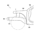
図1に示すように、自動車の車体前部に位置するエンジンルームを構成する車体前部構造90は、車体前部の左右両側に設けられたフロントサイドフレーム91と、左右のフロントサイドフレーム(図1の紙面奥側のフロントサイドフレームは図示せず)91の前端部に架け渡されたフロントバンパビーム93と、左右のフロントサイドフレーム91の外側にそれぞれ設けられたアッパサイドフレーム94とを備えている。
As shown in FIG. 1, a vehicle
フロントサイドフレーム91は、車体前後方向に延びる部材であり、その後端が車室の下方において車体前後方向に延びるフロントフロアフレーム95に連結されている。アッパサイドフレーム94は、車室のドア開口部の前端を構成するフロントピラー96から車体前方向に向かって延びる部材である。本実施形態の連結部材1は、フロントサイドフレーム91とアッパサイドフレーム94とを連結している。
The
<第1実施形態>
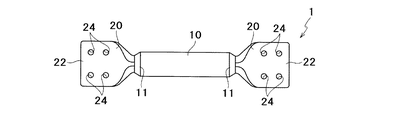
次に、図2を参照しつつ、本発明の第1実施形態にかかる連結部材1の構成について説明する。連結部材1は、円筒状の本体部材10と、本体部材10の両端にそれぞれ接合されたブラケット部材20とで構成されている。本体部材10の両端には縮管部11が設けられており、後で詳述するように、本体部材10とブラケット部材20とは電磁縮管によりかしめ締結されている。本実施形態においては、本体部材10はアルミニウム合金材からなり、ブラケット部材20は軟鋼からなる。すなわち、本体部材10は非磁性体であり、ブラケット部材20は磁性体である。ブラケット部材20には、被連結部材(本実施形態においては、フロントサイドフレーム91またはアッパサイドフレーム94)に取り付けるためのボルトを挿通するボルト孔24が形成されている。本実施形態においては、各ブラケット部材20に4つのボルト孔24が形成されている。
<First Embodiment>
Next, the configuration of the connecting
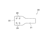
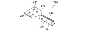
ここで、図3、4をさらに参照しつつ、ブラケット部材20について詳細に説明する。ブラケット部材20は、筒状部21と板状部22とからなる。筒状部21は、円筒状の本体部材10の内側に挿入される部分である。筒状部21は、その一端部において板状部22に連設されている。板状部22は、被連結部材に取り付けられる部分であり、上述のボルト孔24が形成されている。
Here, the
ブラケット部材20は、板状のブランク材1020に曲げ加工を施すことによって形成されており、筒状部21と板状部22とは一体成形される。ブランク材1020は、図4Aに示すように、一方向(紙面の右下方から左上方に向かう方向)一端側に位置する狭幅部1021(右下部分)と、他端側に位置しており狭幅部1021に比べて幅(一方向と直交する方向の長さ)が広い広幅部1022(左上部分)とからなる。狭幅部1021は、ブラケット部材20の完成時に筒状部21となる部分である。広幅部1022は、ブラケット部材20の完成時に板状部22となる部分であり、板状部22のボルト孔24となる孔1024が形成されている。本実施形態においては、ブランク材1020は均一厚さの板部材である。
The
図4Aに示すようなブランク材1020に対して、例えば、狭幅部1021の幅方向中心部分を一方向に延びる棒状の治具に押し当てる等により、狭幅部1021を一方向に延びる円筒状に成形する折り曲げ加工を施し、図4Bに示すようなブラケット部材20を形成する。狭幅部1021の幅方向両端は、筒状に成形された際に僅かな隙間を隔てて離隔する。すなわち、ブラケット部材20の筒状部21には、一方向に延びるスリット23が全長に亘って形成されている。
For example, by pressing the central portion in the width direction of the
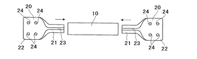
次に、図5A、5B、5Cを参照しつつ、本体部材10にブラケット部材20を電磁縮管によりかしめ締結し、連結部材1を製造する手順について説明する。まず、図5Aに示すように、本体部材10の両端に、ブラケット部材20の筒状部21をそれぞれ挿入する。
Next, a procedure for manufacturing the connecting
そして、図5Bに示すように、筒状部21と本体部材10とが重なり合っている部分の外側に、電磁成形器7を配置する。電磁成形器7は、図示しない電源に接続されたコイル7aと、コイル7aの内側に設けられておりコイル7aから発生される磁束を集中させる磁束集中器7bとで構成されている。すなわち、磁束集中器7bが本体部材10における筒状部21と重なり合っている部分の外周面に対向している。
And as shown to FIG. 5B, the
コイル7aに電源から瞬間大電流が流れると、コイル7aから発生した磁束が磁束集中器7bの本体部材10における筒状部21との重なり部分の外周面との対向面に集中する。このとき、非磁性体である本体部材10に誘導電流が発生し、この誘導電流と電磁場との相互作用によって、本体部材10における筒状部21との重なり部分の外周面と磁束集中器7bとの間隔を拡げるような力、すなわち、本体部材10と筒状部21との重なり部分において本体部材10を縮管するような力(電磁力)が本体部材10に作用する。
When an instantaneous large current flows from the power source to the
一方、ブラケット部材20は磁性体であるので、筒状部21にはほとんど誘導電流が発生しない。加えて、筒状部21においては、スリット23により誘導電流が途切れる。したがって、筒状部21を縮管するような力は筒状部21にはほとんど作用しない。すなわち、外側に配置された本体部材10が縮管する一方で、内側に位置するブラケット部材20の筒状部21は縮管がほとんど生じない。よって、本体部材10と筒状部21との重なり部分が本体部材10の電磁縮管によりかしめ締結される。このとき、ブラケット部材20の筒状部21は内側金型の役割をなし、外側から縮管成形される本体部材10と良好にかしめられる。
On the other hand, since the
なお、電磁成形は、図5Bに示すように、本体部材10の両端に挿入されたブラケット部材20の板状部22を治具8にそれぞれ接触させて、ブラケット部材20を一定位置に固定した状態で行う。
In addition, as shown in FIG. 5B, the electromagnetic forming is a state in which the
上述のように、本体部材10の両端に挿入されたブラケット部材20の筒状部21と本体部材10とを電磁縮管によりかしめ締結することで、図5Cに示すような連結部材1が完成する。
As described above, the
以上に述べたように、本実施形態にかかる連結部材1によれば、ブラケット部材20は、板状のブランク材1020の一方向に関する一端側の一部を一方向に延びる筒状に形成することにより、ブランク材1020の一方向の一端側に設けられて一方向全長に亘って延びるスリット23を有する筒状部21、及びブランク材1020の一方向に関する他端側に設けられた板状部22が一体成形されている。そして、アルミニウム合金材からなる筒状の本体部材10内にブラケット部材20の筒状部21が挿入されており、本体部材10と筒状部21とが電磁縮管によりかしめ締結されている。
したがって、ブランク材1020から筒状部21及び板状部22が一体成形されたブラケット部材20を成形するので、筒状部21及び板状部22の大きさや形状を様々に設定することができる。よって、この連結部材1が適用される構造体の設計の自由度を高めることができる。また、本体部材10とブラケット部材20とを電磁縮管によりかしめ締結しているので、ブラケット部材20を一定位置で固定したままで両者を締結固定でき、且つ、溶接により締結する場合のように熱歪みも生じないので、精度よく連結部材1を製造することができる。さらに、一方向に延びる筒状部21に一方向全長に亘って延びるスリット23が形成されているので、本体部材10内に筒状部21を挿入して本体部材10と筒状部21とを電磁縮管によりかしめ締結する際に、筒状部21においては誘導電流がスリット23で途切れる。よって、外側に配置された非磁性体の本体部材10が縮管する一方で、内側に位置するブラケット部材20の筒状部21は縮管がほとんど生じないので、十分なかしめ力で両者を締結することができる。これにより、連結部材1の強度を高めることができる。
As described above, according to the connecting
Therefore, since the
また、本実施形態の連結部材1では、ブラケット部材20は軟鋼からなる磁性体である。したがって、ブラケット部材20の筒状部21と本体部材10とを電磁縮管によりかしめ締結する際に、筒状部21には誘導電流がほとんど生じず縮管しない。よって、両者を締結するかしめ力をさらに高めることができる。
Moreover, in the
さらに、本実施形態の連結部材1では、非磁性体からなる本体部材10の内側にブラケット部材20の筒状部21を配置し、本体部材10の外側に配置されたコイル7aに電流を流して本体部材10を縮管させることで両者を締結しているので、本体部材10とブラケット部材20との締結部分が大型化することがない。すなわち仮に、非磁性体からなる本体部材10の外側にブラケット部材20の筒状部21を配置する場合には、本体部材10を電磁成形により拡管させる必要があり、本体部材10の内側にコイルを配置しなければならない。また。電磁成形のコイルはコイル径が小さいと十分な拡管力が得られないので、小型化することができない。したがって、本体部材10とブラケット部材20との締結部分が大型化する。
Furthermore, in the connecting
(第1実施形態の変形例)
次に、上述の第1実施形態の第1及び第2の変形例について、図6A、6B、6C、7A、7B、7Cを参照しつつ説明する。第1及び第2の変形例にかかる連結部材は、いずれも上述の第1実施形態のブラケット部材20に相当するブラケット部材120の形状のみが第1実施形態と異なっている。その他の構成については、第1実施形態とほぼ同様であるので、同一の符号を付けて説明を省略する。
(Modification of the first embodiment)
Next, first and second modifications of the first embodiment described above will be described with reference to FIGS. 6A, 6B, 6C, 7A, 7B, and 7C. The connecting members according to the first and second modifications are different from those of the first embodiment only in the shape of the
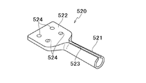
図6A、6Bに示すように、第1の変形例にかかるブラケット部材120を成形するブランク材1120には、狭幅部1121に幅方向に延びており幅方向全長に亘って形成された凹溝1125が形成されている。このようなブランク材1120に曲げ加工を施して、筒状部121及び板状部122を一体成形することで、図6Cに示すようなブラケット部材120が完成する。このとき、ブランク材1120に形成された凹溝1125により、筒状部121において内側に突出する凹みであるビード125が、筒状部121の周方向全周に亘って形成される。
As shown in FIGS. 6A and 6B, the
また、図7A、図7Bに示すように、第2の変形例にかかるブラケット部材220を成形するブランク材1220には、狭幅部1221に平面視で円形形状の凹部1225が複数(本変形例においては4つ)形成されている。このようなブランク材1220に曲げ加工を施して、筒状部221及び板状部222を一体成形することで、図7Cに示すようなブラケット部材220が完成する。このとき、ブランク材1220に形成された凹部1225は、筒状部221において内側に突出する凹みであるディンプル225となる。
Further, as shown in FIGS. 7A and 7B, the
なお、上述の第1及び第2の変形例にかかるブラケット部材120、220においてビード125やディンプル225となる凹溝1125や凹部1225は、プレス成形や圧延成形により設けることができ、ボルト孔124、224となる孔1124、1224と同時に形成することもできる。
In the
上述の第1及び第2の変形例によると、筒状部121(221)と本体部材10とを電磁縮管によりかしめ締結する際に、外側に配置されており縮管する本体部材10が、内側に配置された筒状部121(221)のビード125やディンプル225に入り込む。したがって、締結後に筒状部121(221)と本体部材10とがずれ動くのを防ぐことができる。すなわち、第1の変形例においては、筒状部121の周方向全周に亘って形成されたビード125により、筒状部121が本体部材10から抜けるのを防ぐことができる。第2の変形性においては、ディンプル225により、筒状部221が本体部材10から抜けたり、筒状部221が本体部材10内で回転したりするのを防ぐことができる。
According to the first and second modified examples described above, when the cylindrical portion 121 (221) and the
続いて、上述の第1実施形態の第3及び第4の変形例について、図8A、8B、8Cを参照しつつ説明する。第3及び第4の変形例にかかる連結部材は、いずれも上述の第1実施形態の本体部材10に相当する本体部材310の形状のみが第1実施形態と異なっている。その他の構成については、第1実施形態とほぼ同様であるので、同一の符号を付けて説明を省略する。
Next, third and fourth modifications of the first embodiment described above will be described with reference to FIGS. 8A, 8B, and 8C. The connecting members according to the third and fourth modifications are different from the first embodiment only in the shape of the
図8A、8Bに示すように、第3の変形例にかかる本体部材310には曲げ加工が施されている。すなわち本体部材310は、略中央部分に曲げ部312が設けられた筒状部材である。このように本体部材310を曲げることで、図8Aに示すように、本連結部材301により互いに連結される被連結部材2、3の間に干渉物4がある場合でも、連結部材301を配置することができる。なお、本変形例においては、曲げ部312は1か所のみに設けているが、干渉物4の大きさや形状に応じて複数個所に曲げ部312を設けてもよい。
As shown in FIGS. 8A and 8B, the
また、図8Cに示すように、第4の変形例にかかる本体部材410には中央部分に扁平加工が施されている。すなわち本体部材410は、中央部分に扁平部412が設けられた筒状部材である。このように本体部材410を扁平にすることで、上述の第3の変形例と同様に、被連結部材2、3の間の干渉物4を避けることができる。扁平部412の大きさや設ける位置は、干渉物4の大きさや形状に応じて適宜設定可能であり、例えば、本体部材410の全体に扁平加工が施されていてもよい。
Further, as shown in FIG. 8C, the
さらに、上述の第1実施形態の第5の変形例について、図9A、9Bを参照しつつ説明する。第5の変形例にかかる連結部材は、上述の第1実施形態のブラケット部材20に相当するブラケット部材520の形状のみが第1実施形態と異なっている。その他の構成については、第1実施形態とほぼ同様であるので、同一の符号を付けて説明を省略する。
Furthermore, a fifth modification of the first embodiment described above will be described with reference to FIGS. 9A and 9B. The connecting member according to the fifth modification is different from the first embodiment only in the shape of the
図9A、9Bに示すように、第5の変形例にかかるブラケット部材520を成形するブランク材1520は、いわゆるテーラードブランクであり、狭幅部1521の板厚が広幅部1522の板厚よりも薄くなっている。すなわち、上述のようなブランク材1520から成形されるブラケット部材520においては、筒状部521の板厚が板状部522の板厚よりも薄くなっている。このように、筒状部521と板状部522との板厚を別々に設定することで、様々な構造体に対応して強度を変化させることができる。なお、本変形例においては、筒状部521の板厚が板状部522の板厚よりも薄くなっている場合について説明したが、筒状部521の板厚を板状部522の板厚よりも厚くしてもよい。
As shown in FIGS. 9A and 9B, the
<第2実施形態>
次に、本発明の第2実施形態にかかる連結部材601の構成について説明する。第2実施形態の連結部材601は、ブラケット部材620の構成のみが上述の第1実施形態の連結部材1と異なっている。その他の構成については、第1実施形態とほぼ同様であるので、同一の符号を付けて説明を省略する。
Second Embodiment
Next, the structure of the
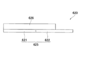
図10、11に示すように、本実施形態のブラケット部材620は、板状のブランク材625と、ブランク材625の一方の表面に接合された補強リブ部材626とで構成されている。ブランク材625は、第1実施形態のブランク材1020と同様に、一方向(図10の左下方から右上方に向かう方向)一端側に位置する狭幅部621と、他端側に位置しており狭幅部621に比べて幅(一方向と直交する方向の長さ)が広い広幅部622とからなる。広幅部622には、ボルト孔24が形成されている。
As shown in FIGS. 10 and 11, the
補強リブ部材626は、ブランク材625の幅方向略中央部分において、一方向(ブランク材625の狭幅部621と広幅部622との配列方向)に沿って延びるように配置されている。補強リブ部材626の長さは、ブランク材625の一方向に沿う長さよりも短い。補強リブ部材626の一端は、ブランク材625の一方向に関して狭幅部621が形成されている側の端と一致しており、他端はブランク材625の広幅部622に位置している。なお、補強リブ部材626の一端は、ブランク材625の一方向に関して狭幅部621が形成されている端と一致していなくてもよく、ブランク材625の狭幅部621に位置していればよい。
The reinforcing
本実施形態においては、ブランク材625と補強リブ部材626とが金属材である場合は摩擦攪拌接合法により接合することができる。この場合、図12に示すようにブランク材625の一方の面(図中下方の面)に補強リブ部材626を当接させた状態で、ブランク材625の他方の面(図中上方の面)側から円筒状の回転ツール901を回転させながら押し当て、その先端に設けられたプローブ902をブランク材625と補強リブ部材626とに差し込む。このとき、回転ツール901のプローブ902とブランク材625及び補強リブ部材626との間に生じる摩擦熱により、ブランク材625と補強リブ部材626との当接部分が塑性流動し、その後冷却固化することでブランク材625と補強リブ部材626とが接合される。
In this embodiment, when the
図10に戻って、ブラケット部材620は、ブランク材625における補強リブ部材626が接合された狭幅部621が円筒状の本体部材10の両端にそれぞれ挿入されている。本実施形態においては、本体部材10内に挿入された補強リブ部材626の延伸方向は、本体部材10の延伸方向と平行となっている。補強リブ部材626の延伸方向は、本体部材10の延伸方向に沿っていればよく、本体部材10の延伸方向と完全に平行な位置からわずかにずれていてもよい。第1実施形態と同様に、本体部材10の両端には縮管部11が設けられており、本体部材10とブラケット部材620とは電磁縮管によりかしめ締結されている。
Returning to FIG. 10, in the
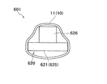
ここで、縮管部11における連結部材601の断面図である図13に示すように、ブラケット部材620の本体部材10内に挿入されている部分の挿入方向に直交する断面はT字形状を有している(図13では上下逆さまのT字となっている)。縮管された本体部材10は、内側に配置されたブラケット部材620の形状に沿って凹凸変形し、部分的に内側に張り出した形状となる。
Here, as shown in FIG. 13, which is a cross-sectional view of the connecting
以上に述べたように、本実施形態にかかる連結部材601によれば、ブラケット部材620は、板状のブランク材625の表面に補強リブ部材626を接合して形成されている。そして、補強リブ部材626の延伸方向が筒状の本体部材10の延伸方向と略平行となるように、本体部材10内にブラケット部材620の補強リブ部材626が接合された部分が挿入されており、ブラケット部材620の本体部材10内に挿入された部分と本体部材10とが電磁縮管によりかしめ締結されている。
したがって、第1実施形態と同様に、本体部材10とブラケット部材620とを電磁縮管によりかしめ締結しているので、精度よく連結部材601を製造することができる。また、板状のブランク材625に補強リブ部材626を接合してブラケット部材620を成形するので、ブラケット部材620の大きさや形状を様々に設定することができる。よって、この連結部材601が適用される構造体の設計の自由度を高めることができる。さらに、ブラケット部材620における本体部材10内に挿入される部分は補強リブ部材626が接合されており高い剛性を有するので、ブラケット部材620と本体部材10とを電磁縮管によりかしめ締結する際に、ブラケット部材620表面に誘導電流が生じてもほとんど変形が生じず、外側に配置された非磁性体の本体部材10のみが縮管する。よって、十分なかしめ力でブラケット部材620と本体部材10とを締結することができる。これにより、連結部材601の強度を高めることができる。また、縮管する本体部材10は、縮管前と同一形状で変形するのではなく、ブラケット部材620の補強リブ部材626が接合された部分の形状に沿って凹凸を有する形状に変形するので、ブラケット部材620と本体部材10との回転方向の強度(回転方向の耐荷重)を強くすることができる。さらに、補強リブ部材626によりブラケット部材620の曲げ荷重を大幅に高めることができる。
As described above, according to the connecting
Therefore, since the
さらに、本実施形態の連結部材601では、ブランク材625と補強リブ部材626とを摩擦攪拌接合法により接合することで、溶融溶接法より被接合部材に対する熱ひずみの影響が少なくすることができ、ブラケット部材620を精度よく作製できる。
Furthermore, in the
(第2実施形態の変形例)
次に、上述の第2実施形態の変形例について、図14A、14B、15を参照しつつ説明する。本変形例にかかる連結部材は、第2実施形態のブラケット部材620に相当するブラケット部材720の形状のみが第2実施形態と異なっている。その他の構成については、第2実施形態とほぼ同様であるので、同一の符号を付けて説明を省略する。
(Modification of the second embodiment)
Next, a modification of the above-described second embodiment will be described with reference to FIGS. 14A, 14B, and 15. FIG. The connecting member according to this modification is different from the second embodiment only in the shape of a
図14Aに示すように、本変形例にかかるブラケット部材720のブランク材725には、狭幅部721と広幅部722と境界部に、ブランク材725の表面に平行であり且つ一方向(ブランク材725の狭幅部721と広幅部722との配列方向であり、補強リブ部材726の延伸方向)と直交する方向に延びる折曲線725aが形成されるように曲げ加工が施されている。また、ブランク材725に接合される補強リブ部材726は、曲げ加工されたブランク材725の形状に沿う形状で形成されている。すなわち、図14Bに示すように、ブラケット部材720は、一方向と直交する方向からの側面視で鈍角をなす形状を有している。
As shown in FIG. 14A, the
さらに、補強リブ部材726は後述するように押出成形により中空状に形成されている。より詳細には、補強リブ部材726の延伸方向に沿う側面におけるブランク材725の狭幅部721に接合される部分と広幅部722に接合される部分とには、それぞれ中空部分727が形成されている。また、狭幅部721に接合される部分の表面には、補強リブ部材726の延伸方向と直交する方向に延びる凹部728が形成されている。これにより、ブラケット部材720と本体部材10とを電磁縮管によりかしめ締結する際に、外側に配置されており縮管する本体部材10が、内側に配置されたブラケット部材720の補強リブ部材726に形成された凹部728に入り込む。したがって、締結後にブラケット部材720と本体部材10とがずれ動くのを防ぐことができる。
Further, the reinforcing
ここで、補強リブ部材726の製造方法について説明する。補強リブ部材726を製造する際には、まず図15に示すように、押出成形により押出方向に延びる折曲線が形成された板状の成形物1726を形成する。このとき同時に押出断面に2つの中空部分1727が形成されるよう成形される。また、成形物1726の表面に押出方向に延びる凹部1728も同時に形成されるようにする。この成形物1726を押出方向と直交する方向に沿って切断することで、多数の補強リブ部材726が連続的に製造される。
Here, a manufacturing method of the reinforcing
本変形例においては、ブラケット部材720に曲げ部を形成することができる。よって、被連結部材の間に干渉物があった場合でも、干渉物を避けて連結部材を配置することができる。よって、構造体の設計の自由度をさらに高めることができる。また、補強リブ部材726を押出成形により押出後に所定の幅で切断することで、多数の補強リブ部材726を連続的に形成でき、押出方向に沿って凹凸を有する形状のブラケット部材を簡単に作成することができる。さらに、補強リブ部材726は中空状に形成することで、連結部材を軽量化することができる。
In this modification, a bent portion can be formed on the
以上、本発明の好適な実施の形態について説明したが、本発明は上述の実施形態や実施例に限られるものではなく、特許請求の範囲に記載した限りにおいて様々な設計変更が可能なものである。 The preferred embodiments of the present invention have been described above. However, the present invention is not limited to the above-described embodiments and examples, and various design changes can be made as long as they are described in the claims. is there.
第1及び第2実施形態の本体部材10及び第1実施形態のブラケット部材20の筒状部21は円筒形状であることに限定されず、例えば断面が楕円形状や四角形状を有する筒形状であってもよい。
The
第1及び第2実施形態においては、本体部材10の両端部にブラケット部材20、620が取り付けられる場合について説明しているが、これには限定されない。すなわち、ブラケット部材20、620は、本体部材10の両端部の少なくとも一方に取り付けられていればよい。
In 1st and 2nd embodiment, although the case where the
ブラケット部材20、620を構成する材料は軟鋼には限定されず、溶接が難しい高張力鋼を用いてもよい。また、ブラケット部材20、620の材料として非磁性体を採用することもできる。したがって、例えば導電率の低い高強度アルミニウム(2000系、7000系)や絶縁性の高い樹脂をブラケット部材20、620の材料として用いてもよい。
The material constituting the
第2実施形態においては、ブラケット部材620のブランク材625と補強リブ部材626とを摩擦攪拌接合法により接合する場合について説明したが、ブランク材625と補強リブ部材626との接合方法はこれに限定されるものではない。すなわち例えば、レーザ溶接、電子ビーム溶接、MIG溶接(metal inert gas welding)等の溶融溶接法で接合してもよく、またボルトで接合してもよく、これらを組み合わせてもよい。更にブランク材625と補強リブ部材626がCFRP(carbon-fiber-reinforced plastic)等の樹脂である場合は接着により接合してもよい。
In 2nd Embodiment, although the case where the
第2実施形態において、ブランク材625の一方の表面に1つの補強リブ部材626が接合されている場合について説明したが、これには限定されない。すなわち、例えばブランク材625の一方の表面に2つ以上の補強リブ部材が接合されていてもよい。また、ブランク材625の両方の表面にそれぞれ補強リブ部材が接合されていてもよい。
In 2nd Embodiment, although the case where the one reinforcing
10 本体部材
20、620 ブラケット部材
21 筒状部
22 板状部
23 スリット
125 ビード
225 ディンプル
626 補強リブ部材
727 中空部分
625、1020 ブランク材(板材)
DESCRIPTION OF
Claims (11)
非磁性体からなる筒状の本体部材の両端部の少なくとも一方の内側に前記ブラケット部材の前記筒状部を挿入し、
前記筒状部と前記本体部材とを電磁縮管によりかしめ締結することを特徴とする構造体の連結部材の製造方法。 By forming a part of one end about a one-way plate material into a cylindrical shape extending in the one direction, the cylinder having a slit extending over the said one direction the entire length is provided on one end side of the direction of the plate Forming a bracket member in which a plate-shaped portion and a plate-shaped portion provided on the other end side in the one direction of the plate material are integrally formed ,
Inserting said tubular portion of said bracket member on at least one of the inner end portions of the cylindrical body member made of a nonmagnetic material,
Method of manufacturing a connecting member of a structure which is characterized that you clinched by electromagnetic condensation tube and said body member and said tubular portion.
非磁性体からなる筒状の本体部材の両端部の少なくとも一方の内側に、前記ブラケット部材の前記補強リブ部材が接合された部分を、前記補強リブ部材の延伸方向が前記本体部材の延伸方向に沿うように、挿入し、
前記ブラケット部材の前記本体部材内に挿入された部分と前記本体部材とを電磁縮管によりかしめ締結することを特徴とする構造体の連結部材の製造方法。 Forming a bracket member by joining one or more reinforcing rib members on the surface of the plate material,
At least one of the inner end portions of the cylindrical body member made of a nonmagnetic material, the reinforcing rib member is bonded portion of the bracket member, the extending direction of the reinforcing rib member in the extending direction of said body member as along, insert,
Method of manufacturing a connecting member of a structure which is characterized that you clinched by electromagnetic condensation tube and said body member and the insertion portion into the body member of the bracket member.
前記補強リブ部材を、曲げ加工された前記板材の形状に沿う形状で形成することを特徴とする請求項4〜6のいずれか一項に記載の構造体の連結部材の製造方法。 Said plate member, and the bent so folding line is formed extending in a direction intersecting the extending direction of the reinforcing rib member on a part of the portion where the reinforcing rib members are joined,
The reinforcing rib member, bending process for the production of the connecting member of the structure according to any one of claims 4-6, characterized that you formed in a shape along the shape of the plate.
Priority Applications (4)
| Application Number | Priority Date | Filing Date | Title |
|---|---|---|---|
| JP2013242985A JP6000932B2 (en) | 2013-02-20 | 2013-11-25 | Method for manufacturing structure connecting member |
| CN201410015246.6A CN103991476B (en) | 2013-02-20 | 2014-01-14 | The coupling member of tectosome |
| US14/154,431 US9352788B2 (en) | 2013-02-20 | 2014-01-14 | Connecting member of structure |
| US14/645,482 US9738327B2 (en) | 2013-02-20 | 2015-03-12 | Connecting member of structure |
Applications Claiming Priority (3)
| Application Number | Priority Date | Filing Date | Title |
|---|---|---|---|
| JP2013031049 | 2013-02-20 | ||
| JP2013031049 | 2013-02-20 | ||
| JP2013242985A JP6000932B2 (en) | 2013-02-20 | 2013-11-25 | Method for manufacturing structure connecting member |
Publications (2)
| Publication Number | Publication Date |
|---|---|
| JP2014184950A JP2014184950A (en) | 2014-10-02 |
| JP6000932B2 true JP6000932B2 (en) | 2016-10-05 |
Family
ID=51305885
Family Applications (1)
| Application Number | Title | Priority Date | Filing Date |
|---|---|---|---|
| JP2013242985A Expired - Fee Related JP6000932B2 (en) | 2013-02-20 | 2013-11-25 | Method for manufacturing structure connecting member |
Country Status (3)
| Country | Link |
|---|---|
| US (2) | US9352788B2 (en) |
| JP (1) | JP6000932B2 (en) |
| CN (1) | CN103991476B (en) |
Families Citing this family (7)
| Publication number | Priority date | Publication date | Assignee | Title |
|---|---|---|---|---|
| JP6000932B2 (en) * | 2013-02-20 | 2016-10-05 | 株式会社神戸製鋼所 | Method for manufacturing structure connecting member |
| JP6005599B2 (en) * | 2013-07-23 | 2016-10-12 | 豊田鉄工株式会社 | Manufacturing method for vehicle floor brace |
| US9939104B2 (en) * | 2014-08-26 | 2018-04-10 | David C. Smith | Magnetic mount |
| DE102015113233A1 (en) * | 2015-08-11 | 2017-02-16 | Meleghy Automotive GmbH & Co. KG | Support device for transmitting loads on a motor vehicle |
| KR101738039B1 (en) * | 2015-10-23 | 2017-05-19 | 현대자동차주식회사 | Structure of hybrid-front pillar |
| JP6489088B2 (en) | 2016-08-26 | 2019-03-27 | トヨタ自動車株式会社 | Vehicle frame structure |
| JP2020003010A (en) * | 2018-06-28 | 2020-01-09 | トヨタ自動車株式会社 | Pipe joint method |
Family Cites Families (36)
| Publication number | Priority date | Publication date | Assignee | Title |
|---|---|---|---|---|
| US1576874A (en) * | 1922-07-08 | 1926-03-16 | Bausch & Lomb | Method of making connections between metal and nonmetallic members |
| US2752179A (en) * | 1951-01-26 | 1956-06-26 | Fuller Brush Co | Tube and socket connection and method of making |
| US2883216A (en) * | 1953-11-20 | 1959-04-21 | Painter Brothers Ltd | End and like connections for galvanised structural tubes and similar elements |
| US2794689A (en) * | 1955-06-20 | 1957-06-04 | Rubrum Moses | Handle fastening for garden tool |
| US2918175A (en) * | 1958-07-29 | 1959-12-22 | Gordon M Mcdonald | Curtain rod with integral attachment means |
| US3358354A (en) * | 1963-03-21 | 1967-12-19 | Voss | Methods of making hygienic devices |
| US4286893A (en) * | 1980-05-12 | 1981-09-01 | Francis Pomares | Handle attaching means for rakes and the like |
| US4806042A (en) * | 1987-11-19 | 1989-02-21 | The Fluorocarbon Company | Quick-disconnect rigid coupling |
| US5343015A (en) * | 1992-11-06 | 1994-08-30 | Fintube Limited Partnership | Laser assisted high frequency welding |
| US5606790A (en) * | 1993-04-09 | 1997-03-04 | Charles E. Laue | Method of making a two piece pedal rod |
| US5425286A (en) * | 1993-04-09 | 1995-06-20 | Laue; Charles E. | Two piece pedal rod and method of making same |
| ES2177818T3 (en) * | 1995-12-20 | 2002-12-16 | Pulsar Welding Ltd | ELECTROMAGNETIC UNION OR WELDING OF METAL OBJECTS. |
| US5617697A (en) * | 1996-01-03 | 1997-04-08 | Erwin Industries, Inc. | Composite deck post |
| JPH1035235A (en) * | 1996-07-26 | 1998-02-10 | Showa Alum Corp | Suspension arm member |
| JPH1061435A (en) * | 1996-08-21 | 1998-03-03 | Honda Motor Co Ltd | Muffler and its manufacture |
| US5791708A (en) * | 1997-05-01 | 1998-08-11 | Capriotti; Chris | Trenching tool and method |
| US5862642A (en) * | 1997-10-28 | 1999-01-26 | Erwin Industries, Inc. | Reinforced composite deck post |
| JP4297548B2 (en) * | 1999-03-16 | 2009-07-15 | 株式会社神戸製鋼所 | Manufacturing method of body frame |
| US6688803B2 (en) * | 1999-12-23 | 2004-02-10 | Royal Packaging Industries Van Leer N.V. | Connection assembly |
| GB2362183A (en) * | 2000-05-10 | 2001-11-14 | Secr Defence | Method of reinforcing structures |
| US6406077B2 (en) * | 2000-05-11 | 2002-06-18 | Shape Corporation | Tube with extruded flanges holding wall-reinforcing insert |
| US6389697B1 (en) * | 2000-07-17 | 2002-05-21 | Fuel Cell Components And Integrators, Inc. | Fabricating automotive spaceframes using electromagnetic forming or magnetic pulse welding |
| US6766608B1 (en) * | 2002-07-30 | 2004-07-27 | Larry Jelmyer | Apparatus for bait harness |
| JP2004106704A (en) | 2002-09-18 | 2004-04-08 | Fuji Heavy Ind Ltd | Front body structure of automobile |
| US7225588B2 (en) * | 2003-07-08 | 2007-06-05 | Nippon Steel Corporation | Damping brace and structure |
| KR100527482B1 (en) * | 2003-11-10 | 2005-11-09 | 현대자동차주식회사 | Combination device using electromagnetic molding |
| JP4649360B2 (en) * | 2006-04-07 | 2011-03-09 | 新日本製鐵株式会社 | Seismic joint structure and construction method thereof |
| CN101432490A (en) * | 2006-04-27 | 2009-05-13 | 杰弗里·艾伦·帕克 | Cast structural connectors |
| US7703161B1 (en) * | 2007-07-02 | 2010-04-27 | Darran Michael Handshaw | Vehicle extrication preparatory tool |
| JP2009184424A (en) * | 2008-02-04 | 2009-08-20 | Honda Motor Co Ltd | Vehicle body front structure |
| DE102009056923A1 (en) * | 2009-12-03 | 2011-06-09 | GM Global Technology Operations LLC, ( n. d. Ges. d. Staates Delaware ), Detroit | Deformation element, vehicle bumper carrier with deformation element and method for producing a deformation element |
| US20110232221A1 (en) * | 2010-03-25 | 2011-09-29 | National Applied Research Laboratories | Buckling restrained brace |
| DE102010053843A1 (en) * | 2010-12-08 | 2012-06-14 | Daimler Ag | joint assembly |
| US8757798B2 (en) * | 2012-08-31 | 2014-06-24 | Cody Air LLC | Eyewear frame |
| USD701097S1 (en) * | 2012-12-24 | 2014-03-18 | Innovative Garden Products, LLC | Rake |
| JP6000932B2 (en) * | 2013-02-20 | 2016-10-05 | 株式会社神戸製鋼所 | Method for manufacturing structure connecting member |
-
2013
- 2013-11-25 JP JP2013242985A patent/JP6000932B2/en not_active Expired - Fee Related
-
2014
- 2014-01-14 US US14/154,431 patent/US9352788B2/en not_active Expired - Fee Related
- 2014-01-14 CN CN201410015246.6A patent/CN103991476B/en not_active Expired - Fee Related
-
2015
- 2015-03-12 US US14/645,482 patent/US9738327B2/en not_active Expired - Fee Related
Also Published As
| Publication number | Publication date |
|---|---|
| CN103991476B (en) | 2016-04-06 |
| JP2014184950A (en) | 2014-10-02 |
| US9352788B2 (en) | 2016-05-31 |
| US20140234018A1 (en) | 2014-08-21 |
| US9738327B2 (en) | 2017-08-22 |
| CN103991476A (en) | 2014-08-20 |
| US20150183470A1 (en) | 2015-07-02 |
Similar Documents
| Publication | Publication Date | Title |
|---|---|---|
| JP6000932B2 (en) | Method for manufacturing structure connecting member | |
| JP5597713B2 (en) | Structural members for automobiles | |
| JP7181016B2 (en) | Bonded structure and manufacturing method thereof | |
| US20140294489A1 (en) | Member joining method and member joining structure | |
| US20060059807A1 (en) | Frame system for motor vehicle | |
| JP5706021B1 (en) | Structural member and method of manufacturing the structural member | |
| JP5382271B1 (en) | Joint structure | |
| US20130320685A1 (en) | Automobile bumper structure | |
| JP2015077610A (en) | Laser joining structure and laser joining method | |
| US20150217821A1 (en) | Method of Setting Vehicle Geometry and Structural Joining | |
| WO2017065231A1 (en) | Method for joining mutual members constituting frame structure mounted on automobile, and frame structure mounted on automobile | |
| JP3830340B2 (en) | Manufacturing method of bonded structure | |
| JP6891763B2 (en) | Vehicle joint structure | |
| WO2018142859A1 (en) | Method for joining dissimilar materials, and dissimilar-material joined body | |
| JP5970016B2 (en) | Member joint structure | |
| JP4752727B2 (en) | Vehicle pillar structure | |
| JP2019043439A (en) | Bumper system | |
| US10486744B2 (en) | Vehicle frame member | |
| JP5863012B2 (en) | Joining method between long members | |
| WO2021192188A1 (en) | Structure and method for manufacturing structure | |
| JP5637904B2 (en) | Member connection structure | |
| JP5852497B2 (en) | Hollow member for reinforcement and manufacturing method thereof | |
| JP5797856B2 (en) | Vehicle door frame | |
| JP4923137B2 (en) | Vehicle bulkhead structure | |
| JP2020104807A (en) | Vehicle pillar |
Legal Events
| Date | Code | Title | Description |
|---|---|---|---|
| A621 | Written request for application examination |
Free format text: JAPANESE INTERMEDIATE CODE: A621 Effective date: 20150901 |
|
| A977 | Report on retrieval |
Free format text: JAPANESE INTERMEDIATE CODE: A971007 Effective date: 20160609 |
|
| A131 | Notification of reasons for refusal |
Free format text: JAPANESE INTERMEDIATE CODE: A131 Effective date: 20160621 |
|
| A521 | Request for written amendment filed |
Free format text: JAPANESE INTERMEDIATE CODE: A523 Effective date: 20160721 |
|
| RD02 | Notification of acceptance of power of attorney |
Free format text: JAPANESE INTERMEDIATE CODE: A7422 Effective date: 20160721 |
|
| RD04 | Notification of resignation of power of attorney |
Free format text: JAPANESE INTERMEDIATE CODE: A7424 Effective date: 20160722 |
|
| TRDD | Decision of grant or rejection written | ||
| A01 | Written decision to grant a patent or to grant a registration (utility model) |
Free format text: JAPANESE INTERMEDIATE CODE: A01 Effective date: 20160830 |
|
| A61 | First payment of annual fees (during grant procedure) |
Free format text: JAPANESE INTERMEDIATE CODE: A61 Effective date: 20160831 |
|
| R150 | Certificate of patent or registration of utility model |
Ref document number: 6000932 Country of ref document: JP Free format text: JAPANESE INTERMEDIATE CODE: R150 |
|
| LAPS | Cancellation because of no payment of annual fees |