JP5999713B2 - System and method for closing an incision - Google Patents
System and method for closing an incision Download PDFInfo
- Publication number
- JP5999713B2 JP5999713B2 JP2013508247A JP2013508247A JP5999713B2 JP 5999713 B2 JP5999713 B2 JP 5999713B2 JP 2013508247 A JP2013508247 A JP 2013508247A JP 2013508247 A JP2013508247 A JP 2013508247A JP 5999713 B2 JP5999713 B2 JP 5999713B2
- Authority
- JP
- Japan
- Prior art keywords
- scaffold
- incision
- fluidly coupled
- conduit
- manifold
- Prior art date
- Legal status (The legal status is an assumption and is not a legal conclusion. Google has not performed a legal analysis and makes no representation as to the accuracy of the status listed.)
- Expired - Fee Related
Links
- 238000000034 method Methods 0.000 title description 6
- 239000012530 fluid Substances 0.000 claims description 37
- 239000000463 material Substances 0.000 claims description 15
- 239000011148 porous material Substances 0.000 claims description 12
- 102000008186 Collagen Human genes 0.000 claims description 4
- 108010035532 Collagen Proteins 0.000 claims description 4
- 229920001436 collagen Polymers 0.000 claims description 4
- 229920002635 polyurethane Polymers 0.000 claims description 4
- 239000004814 polyurethane Substances 0.000 claims description 4
- 230000001939 inductive effect Effects 0.000 claims description 3
- 230000008878 coupling Effects 0.000 claims description 2
- 238000010168 coupling process Methods 0.000 claims description 2
- 238000005859 coupling reaction Methods 0.000 claims description 2
- 239000012620 biological material Substances 0.000 claims 2
- 210000001519 tissue Anatomy 0.000 description 41
- 239000011159 matrix material Substances 0.000 description 9
- 208000027418 Wounds and injury Diseases 0.000 description 8
- 210000002615 epidermis Anatomy 0.000 description 8
- 206010052428 Wound Diseases 0.000 description 7
- 230000008901 benefit Effects 0.000 description 7
- 238000004891 communication Methods 0.000 description 7
- 210000004027 cell Anatomy 0.000 description 6
- 102000004169 proteins and genes Human genes 0.000 description 5
- 108090000623 proteins and genes Proteins 0.000 description 5
- 230000017423 tissue regeneration Effects 0.000 description 5
- 229920000954 Polyglycolide Polymers 0.000 description 4
- 230000007547 defect Effects 0.000 description 4
- 230000035876 healing Effects 0.000 description 4
- 239000004633 polyglycolic acid Substances 0.000 description 4
- 238000002560 therapeutic procedure Methods 0.000 description 4
- 239000000853 adhesive Substances 0.000 description 3
- 230000001070 adhesive effect Effects 0.000 description 3
- 230000006837 decompression Effects 0.000 description 3
- 239000006260 foam Substances 0.000 description 3
- 239000003102 growth factor Substances 0.000 description 3
- 239000010410 layer Substances 0.000 description 3
- 238000012986 modification Methods 0.000 description 3
- 230000004048 modification Effects 0.000 description 3
- 206010033675 panniculitis Diseases 0.000 description 3
- 230000002093 peripheral effect Effects 0.000 description 3
- 230000008439 repair process Effects 0.000 description 3
- 210000004304 subcutaneous tissue Anatomy 0.000 description 3
- 239000000126 substance Substances 0.000 description 3
- VTYYLEPIZMXCLO-UHFFFAOYSA-L Calcium carbonate Chemical compound [Ca+2].[O-]C([O-])=O VTYYLEPIZMXCLO-UHFFFAOYSA-L 0.000 description 2
- LYCAIKOWRPUZTN-UHFFFAOYSA-N Ethylene glycol Chemical compound OCCO LYCAIKOWRPUZTN-UHFFFAOYSA-N 0.000 description 2
- 102000010834 Extracellular Matrix Proteins Human genes 0.000 description 2
- 108010037362 Extracellular Matrix Proteins Proteins 0.000 description 2
- FAPWRFPIFSIZLT-UHFFFAOYSA-M Sodium chloride Chemical compound [Na+].[Cl-] FAPWRFPIFSIZLT-UHFFFAOYSA-M 0.000 description 2
- 239000002253 acid Substances 0.000 description 2
- OSGAYBCDTDRGGQ-UHFFFAOYSA-L calcium sulfate Chemical compound [Ca+2].[O-]S([O-])(=O)=O OSGAYBCDTDRGGQ-UHFFFAOYSA-L 0.000 description 2
- 230000010261 cell growth Effects 0.000 description 2
- 230000012292 cell migration Effects 0.000 description 2
- 239000003795 chemical substances by application Substances 0.000 description 2
- 230000006378 damage Effects 0.000 description 2
- 238000005516 engineering process Methods 0.000 description 2
- 230000006870 function Effects 0.000 description 2
- 239000000499 gel Substances 0.000 description 2
- 150000004676 glycans Chemical class 0.000 description 2
- 230000012010 growth Effects 0.000 description 2
- 229910052588 hydroxylapatite Inorganic materials 0.000 description 2
- 208000014674 injury Diseases 0.000 description 2
- 239000007788 liquid Substances 0.000 description 2
- 238000013508 migration Methods 0.000 description 2
- 230000037361 pathway Effects 0.000 description 2
- XYJRXVWERLGGKC-UHFFFAOYSA-D pentacalcium;hydroxide;triphosphate Chemical compound [OH-].[Ca+2].[Ca+2].[Ca+2].[Ca+2].[Ca+2].[O-]P([O-])([O-])=O.[O-]P([O-])([O-])=O.[O-]P([O-])([O-])=O XYJRXVWERLGGKC-UHFFFAOYSA-D 0.000 description 2
- 239000004626 polylactic acid Substances 0.000 description 2
- 229920000642 polymer Polymers 0.000 description 2
- 229920001282 polysaccharide Polymers 0.000 description 2
- 239000005017 polysaccharide Substances 0.000 description 2
- 238000012545 processing Methods 0.000 description 2
- 238000011069 regeneration method Methods 0.000 description 2
- 239000011780 sodium chloride Substances 0.000 description 2
- 238000007920 subcutaneous administration Methods 0.000 description 2
- 230000000153 supplemental effect Effects 0.000 description 2
- 230000008467 tissue growth Effects 0.000 description 2
- 239000011800 void material Substances 0.000 description 2
- KIUKXJAPPMFGSW-DNGZLQJQSA-N (2S,3S,4S,5R,6R)-6-[(2S,3R,4R,5S,6R)-3-Acetamido-2-[(2S,3S,4R,5R,6R)-6-[(2R,3R,4R,5S,6R)-3-acetamido-2,5-dihydroxy-6-(hydroxymethyl)oxan-4-yl]oxy-2-carboxy-4,5-dihydroxyoxan-3-yl]oxy-5-hydroxy-6-(hydroxymethyl)oxan-4-yl]oxy-3,4,5-trihydroxyoxane-2-carboxylic acid Chemical compound CC(=O)N[C@H]1[C@H](O)O[C@H](CO)[C@@H](O)[C@@H]1O[C@H]1[C@H](O)[C@@H](O)[C@H](O[C@H]2[C@@H]([C@@H](O[C@H]3[C@@H]([C@@H](O)[C@H](O)[C@H](O3)C(O)=O)O)[C@H](O)[C@@H](CO)O2)NC(C)=O)[C@@H](C(O)=O)O1 KIUKXJAPPMFGSW-DNGZLQJQSA-N 0.000 description 1
- FHVDTGUDJYJELY-UHFFFAOYSA-N 6-{[2-carboxy-4,5-dihydroxy-6-(phosphanyloxy)oxan-3-yl]oxy}-4,5-dihydroxy-3-phosphanyloxane-2-carboxylic acid Chemical compound O1C(C(O)=O)C(P)C(O)C(O)C1OC1C(C(O)=O)OC(OP)C(O)C1O FHVDTGUDJYJELY-UHFFFAOYSA-N 0.000 description 1
- 229920001661 Chitosan Polymers 0.000 description 1
- 102000004127 Cytokines Human genes 0.000 description 1
- 108090000695 Cytokines Proteins 0.000 description 1
- 206010063560 Excessive granulation tissue Diseases 0.000 description 1
- 102000009123 Fibrin Human genes 0.000 description 1
- 108010073385 Fibrin Proteins 0.000 description 1
- BWGVNKXGVNDBDI-UHFFFAOYSA-N Fibrin monomer Chemical compound CNC(=O)CNC(=O)CN BWGVNKXGVNDBDI-UHFFFAOYSA-N 0.000 description 1
- 102000016359 Fibronectins Human genes 0.000 description 1
- 108010067306 Fibronectins Proteins 0.000 description 1
- 206010016717 Fistula Diseases 0.000 description 1
- 208000005422 Foreign-Body reaction Diseases 0.000 description 1
- 208000034693 Laceration Diseases 0.000 description 1
- 239000004677 Nylon Substances 0.000 description 1
- RVGRUAULSDPKGF-UHFFFAOYSA-N Poloxamer Chemical compound C1CO1.CC1CO1 RVGRUAULSDPKGF-UHFFFAOYSA-N 0.000 description 1
- 229920003171 Poly (ethylene oxide) Polymers 0.000 description 1
- 239000004952 Polyamide Substances 0.000 description 1
- 229920002732 Polyanhydride Polymers 0.000 description 1
- 239000004698 Polyethylene Substances 0.000 description 1
- 239000002202 Polyethylene glycol Substances 0.000 description 1
- 229920001710 Polyorthoester Polymers 0.000 description 1
- 239000004793 Polystyrene Substances 0.000 description 1
- 239000004372 Polyvinyl alcohol Substances 0.000 description 1
- 229920001247 Reticulated foam Polymers 0.000 description 1
- 229920006362 Teflon® Polymers 0.000 description 1
- 238000010521 absorption reaction Methods 0.000 description 1
- 230000001133 acceleration Effects 0.000 description 1
- 239000013543 active substance Substances 0.000 description 1
- 125000002252 acyl group Chemical group 0.000 description 1
- 239000012790 adhesive layer Substances 0.000 description 1
- 229940072056 alginate Drugs 0.000 description 1
- 235000010443 alginic acid Nutrition 0.000 description 1
- 229920000615 alginic acid Polymers 0.000 description 1
- 239000003242 anti bacterial agent Substances 0.000 description 1
- 239000003443 antiviral agent Substances 0.000 description 1
- 229910052586 apatite Inorganic materials 0.000 description 1
- 230000000712 assembly Effects 0.000 description 1
- 238000000429 assembly Methods 0.000 description 1
- 229910000063 azene Inorganic materials 0.000 description 1
- 239000011230 binding agent Substances 0.000 description 1
- 239000005312 bioglass Substances 0.000 description 1
- 230000015572 biosynthetic process Effects 0.000 description 1
- 229920001400 block copolymer Polymers 0.000 description 1
- DQXBYHZEEUGOBF-UHFFFAOYSA-N but-3-enoic acid;ethene Chemical compound C=C.OC(=O)CC=C DQXBYHZEEUGOBF-UHFFFAOYSA-N 0.000 description 1
- 239000000648 calcium alginate Substances 0.000 description 1
- 235000010410 calcium alginate Nutrition 0.000 description 1
- 229960002681 calcium alginate Drugs 0.000 description 1
- 229910000019 calcium carbonate Inorganic materials 0.000 description 1
- 239000001506 calcium phosphate Substances 0.000 description 1
- 229910000389 calcium phosphate Inorganic materials 0.000 description 1
- 235000011010 calcium phosphates Nutrition 0.000 description 1
- OKHHGHGGPDJQHR-YMOPUZKJSA-L calcium;(2s,3s,4s,5s,6r)-6-[(2r,3s,4r,5s,6r)-2-carboxy-6-[(2r,3s,4r,5s,6r)-2-carboxylato-4,5,6-trihydroxyoxan-3-yl]oxy-4,5-dihydroxyoxan-3-yl]oxy-3,4,5-trihydroxyoxane-2-carboxylate Chemical compound [Ca+2].O[C@@H]1[C@H](O)[C@H](O)O[C@@H](C([O-])=O)[C@H]1O[C@H]1[C@@H](O)[C@@H](O)[C@H](O[C@H]2[C@H]([C@@H](O)[C@H](O)[C@H](O2)C([O-])=O)O)[C@H](C(O)=O)O1 OKHHGHGGPDJQHR-YMOPUZKJSA-L 0.000 description 1
- 150000004649 carbonic acid derivatives Chemical class 0.000 description 1
- 230000015556 catabolic process Effects 0.000 description 1
- 230000009087 cell motility Effects 0.000 description 1
- 230000004663 cell proliferation Effects 0.000 description 1
- 230000001413 cellular effect Effects 0.000 description 1
- 229920002301 cellulose acetate Polymers 0.000 description 1
- 239000000919 ceramic Substances 0.000 description 1
- 239000002131 composite material Substances 0.000 description 1
- 230000007850 degeneration Effects 0.000 description 1
- 238000006731 degradation reaction Methods 0.000 description 1
- 210000004207 dermis Anatomy 0.000 description 1
- 238000013461 design Methods 0.000 description 1
- 238000009792 diffusion process Methods 0.000 description 1
- 239000013536 elastomeric material Substances 0.000 description 1
- 239000005038 ethylene vinyl acetate Substances 0.000 description 1
- 210000002744 extracellular matrix Anatomy 0.000 description 1
- 210000000416 exudates and transudate Anatomy 0.000 description 1
- 238000009950 felting Methods 0.000 description 1
- 239000000835 fiber Substances 0.000 description 1
- 229950003499 fibrin Drugs 0.000 description 1
- 238000001914 filtration Methods 0.000 description 1
- 230000003890 fistula Effects 0.000 description 1
- 210000001126 granulation tissue Anatomy 0.000 description 1
- 239000007952 growth promoter Substances 0.000 description 1
- 229920002674 hyaluronan Polymers 0.000 description 1
- 229960003160 hyaluronic acid Drugs 0.000 description 1
- 239000000017 hydrogel Substances 0.000 description 1
- WGCNASOHLSPBMP-UHFFFAOYSA-N hydroxyacetaldehyde Natural products OCC=O WGCNASOHLSPBMP-UHFFFAOYSA-N 0.000 description 1
- 230000002163 immunogen Effects 0.000 description 1
- 230000002262 irrigation Effects 0.000 description 1
- 238000003973 irrigation Methods 0.000 description 1
- 230000005012 migration Effects 0.000 description 1
- 229920005615 natural polymer Polymers 0.000 description 1
- 235000015097 nutrients Nutrition 0.000 description 1
- 235000016709 nutrition Nutrition 0.000 description 1
- 230000035764 nutrition Effects 0.000 description 1
- 229920001778 nylon Polymers 0.000 description 1
- 210000000056 organ Anatomy 0.000 description 1
- VSIIXMUUUJUKCM-UHFFFAOYSA-D pentacalcium;fluoride;triphosphate Chemical compound [F-].[Ca+2].[Ca+2].[Ca+2].[Ca+2].[Ca+2].[O-]P([O-])([O-])=O.[O-]P([O-])([O-])=O.[O-]P([O-])([O-])=O VSIIXMUUUJUKCM-UHFFFAOYSA-D 0.000 description 1
- 229920001983 poloxamer Polymers 0.000 description 1
- 229960000502 poloxamer Drugs 0.000 description 1
- 229920002006 poly(N-vinylimidazole) polymer Polymers 0.000 description 1
- 229920001308 poly(aminoacid) Polymers 0.000 description 1
- 229920001200 poly(ethylene-vinyl acetate) Polymers 0.000 description 1
- 229920002463 poly(p-dioxanone) polymer Polymers 0.000 description 1
- 229920002627 poly(phosphazenes) Polymers 0.000 description 1
- 229920000058 polyacrylate Polymers 0.000 description 1
- 229920002647 polyamide Polymers 0.000 description 1
- 229920001610 polycaprolactone Polymers 0.000 description 1
- 239000004632 polycaprolactone Substances 0.000 description 1
- 229920000515 polycarbonate Polymers 0.000 description 1
- 239000004417 polycarbonate Substances 0.000 description 1
- 229920002721 polycyanoacrylate Polymers 0.000 description 1
- 239000000622 polydioxanone Substances 0.000 description 1
- -1 polyethylene Polymers 0.000 description 1
- 229920000573 polyethylene Polymers 0.000 description 1
- 229920001223 polyethylene glycol Polymers 0.000 description 1
- 229920000098 polyolefin Polymers 0.000 description 1
- 229920006324 polyoxymethylene Polymers 0.000 description 1
- 229920001451 polypropylene glycol Polymers 0.000 description 1
- 229920002223 polystyrene Polymers 0.000 description 1
- 229920002451 polyvinyl alcohol Polymers 0.000 description 1
- 239000004800 polyvinyl chloride Substances 0.000 description 1
- 229920000915 polyvinyl chloride Polymers 0.000 description 1
- 229920002620 polyvinyl fluoride Polymers 0.000 description 1
- 229920000036 polyvinylpyrrolidone Polymers 0.000 description 1
- 235000013855 polyvinylpyrrolidone Nutrition 0.000 description 1
- 239000001267 polyvinylpyrrolidone Substances 0.000 description 1
- 230000008569 process Effects 0.000 description 1
- 230000001737 promoting effect Effects 0.000 description 1
- 230000009467 reduction Effects 0.000 description 1
- 238000007789 sealing Methods 0.000 description 1
- 210000003491 skin Anatomy 0.000 description 1
- 239000007779 soft material Substances 0.000 description 1
- 210000004872 soft tissue Anatomy 0.000 description 1
- 238000001179 sorption measurement Methods 0.000 description 1
- 239000013589 supplement Substances 0.000 description 1
- 238000001356 surgical procedure Methods 0.000 description 1
- 229920001059 synthetic polymer Polymers 0.000 description 1
- 229920001897 terpolymer Polymers 0.000 description 1
- 230000009772 tissue formation Effects 0.000 description 1
- 230000008733 trauma Effects 0.000 description 1
- QORWJWZARLRLPR-UHFFFAOYSA-H tricalcium bis(phosphate) Chemical compound [Ca+2].[Ca+2].[Ca+2].[O-]P([O-])([O-])=O.[O-]P([O-])([O-])=O QORWJWZARLRLPR-UHFFFAOYSA-H 0.000 description 1
- 230000002792 vascular Effects 0.000 description 1
- XLYOFNOQVPJJNP-UHFFFAOYSA-N water Substances O XLYOFNOQVPJJNP-UHFFFAOYSA-N 0.000 description 1
- PAPBSGBWRJIAAV-UHFFFAOYSA-N ε-Caprolactone Chemical compound O=C1CCCCCO1 PAPBSGBWRJIAAV-UHFFFAOYSA-N 0.000 description 1
Images

Classifications
-
- A—HUMAN NECESSITIES
- A61—MEDICAL OR VETERINARY SCIENCE; HYGIENE
- A61B—DIAGNOSIS; SURGERY; IDENTIFICATION
- A61B17/00—Surgical instruments, devices or methods, e.g. tourniquets
- A61B17/08—Wound clamps or clips, i.e. not or only partly penetrating the tissue ; Devices for bringing together the edges of a wound
- A61B17/085—Wound clamps or clips, i.e. not or only partly penetrating the tissue ; Devices for bringing together the edges of a wound with adhesive layer
-
- A—HUMAN NECESSITIES
- A61—MEDICAL OR VETERINARY SCIENCE; HYGIENE
- A61B—DIAGNOSIS; SURGERY; IDENTIFICATION
- A61B17/00—Surgical instruments, devices or methods, e.g. tourniquets
- A61B17/08—Wound clamps or clips, i.e. not or only partly penetrating the tissue ; Devices for bringing together the edges of a wound
-
- A61F13/05—
-
- A—HUMAN NECESSITIES
- A61—MEDICAL OR VETERINARY SCIENCE; HYGIENE
- A61M—DEVICES FOR INTRODUCING MEDIA INTO, OR ONTO, THE BODY; DEVICES FOR TRANSDUCING BODY MEDIA OR FOR TAKING MEDIA FROM THE BODY; DEVICES FOR PRODUCING OR ENDING SLEEP OR STUPOR
- A61M1/00—Suction or pumping devices for medical purposes; Devices for carrying-off, for treatment of, or for carrying-over, body-liquids; Drainage systems
- A61M1/90—Negative pressure wound therapy devices, i.e. devices for applying suction to a wound to promote healing, e.g. including a vacuum dressing
- A61M1/91—Suction aspects of the dressing
- A61M1/915—Constructional details of the pressure distribution manifold
-
- A—HUMAN NECESSITIES
- A61—MEDICAL OR VETERINARY SCIENCE; HYGIENE
- A61M—DEVICES FOR INTRODUCING MEDIA INTO, OR ONTO, THE BODY; DEVICES FOR TRANSDUCING BODY MEDIA OR FOR TAKING MEDIA FROM THE BODY; DEVICES FOR PRODUCING OR ENDING SLEEP OR STUPOR
- A61M1/00—Suction or pumping devices for medical purposes; Devices for carrying-off, for treatment of, or for carrying-over, body-liquids; Drainage systems
- A61M1/90—Negative pressure wound therapy devices, i.e. devices for applying suction to a wound to promote healing, e.g. including a vacuum dressing
- A61M1/91—Suction aspects of the dressing
- A61M1/916—Suction aspects of the dressing specially adapted for deep wounds
-
- A—HUMAN NECESSITIES
- A61—MEDICAL OR VETERINARY SCIENCE; HYGIENE
- A61B—DIAGNOSIS; SURGERY; IDENTIFICATION
- A61B17/00—Surgical instruments, devices or methods, e.g. tourniquets
- A61B2017/00004—(bio)absorbable, (bio)resorbable, resorptive
-
- A—HUMAN NECESSITIES
- A61—MEDICAL OR VETERINARY SCIENCE; HYGIENE
- A61B—DIAGNOSIS; SURGERY; IDENTIFICATION
- A61B17/00—Surgical instruments, devices or methods, e.g. tourniquets
- A61B2017/00831—Material properties
- A61B2017/00893—Material properties pharmaceutically effective
-
- A—HUMAN NECESSITIES
- A61—MEDICAL OR VETERINARY SCIENCE; HYGIENE
- A61B—DIAGNOSIS; SURGERY; IDENTIFICATION
- A61B17/00—Surgical instruments, devices or methods, e.g. tourniquets
- A61B17/08—Wound clamps or clips, i.e. not or only partly penetrating the tissue ; Devices for bringing together the edges of a wound
- A61B2017/081—Tissue approximator
-
- A—HUMAN NECESSITIES
- A61—MEDICAL OR VETERINARY SCIENCE; HYGIENE
- A61B—DIAGNOSIS; SURGERY; IDENTIFICATION
- A61B17/00—Surgical instruments, devices or methods, e.g. tourniquets
- A61B17/30—Surgical pincettes without pivotal connections
- A61B2017/306—Surgical pincettes without pivotal connections holding by means of suction
-
- A—HUMAN NECESSITIES
- A61—MEDICAL OR VETERINARY SCIENCE; HYGIENE
- A61B—DIAGNOSIS; SURGERY; IDENTIFICATION
- A61B90/00—Instruments, implements or accessories specially adapted for surgery or diagnosis and not covered by any of the groups A61B1/00 - A61B50/00, e.g. for luxation treatment or for protecting wound edges
- A61B90/06—Measuring instruments not otherwise provided for
- A61B2090/064—Measuring instruments not otherwise provided for for measuring force, pressure or mechanical tension
- A61B2090/065—Measuring instruments not otherwise provided for for measuring force, pressure or mechanical tension for measuring contact or contact pressure
-
- A—HUMAN NECESSITIES
- A61—MEDICAL OR VETERINARY SCIENCE; HYGIENE
- A61F—FILTERS IMPLANTABLE INTO BLOOD VESSELS; PROSTHESES; DEVICES PROVIDING PATENCY TO, OR PREVENTING COLLAPSING OF, TUBULAR STRUCTURES OF THE BODY, e.g. STENTS; ORTHOPAEDIC, NURSING OR CONTRACEPTIVE DEVICES; FOMENTATION; TREATMENT OR PROTECTION OF EYES OR EARS; BANDAGES, DRESSINGS OR ABSORBENT PADS; FIRST-AID KITS
- A61F13/00—Bandages or dressings; Absorbent pads
- A61F2013/00089—Wound bandages
- A61F2013/00217—Wound bandages not adhering to the wound
- A61F2013/00221—Wound bandages not adhering to the wound biodegradable, non-irritating
-
- A—HUMAN NECESSITIES
- A61—MEDICAL OR VETERINARY SCIENCE; HYGIENE
- A61F—FILTERS IMPLANTABLE INTO BLOOD VESSELS; PROSTHESES; DEVICES PROVIDING PATENCY TO, OR PREVENTING COLLAPSING OF, TUBULAR STRUCTURES OF THE BODY, e.g. STENTS; ORTHOPAEDIC, NURSING OR CONTRACEPTIVE DEVICES; FOMENTATION; TREATMENT OR PROTECTION OF EYES OR EARS; BANDAGES, DRESSINGS OR ABSORBENT PADS; FIRST-AID KITS
- A61F13/00—Bandages or dressings; Absorbent pads
- A61F2013/00361—Plasters
- A61F2013/00365—Plasters use
- A61F2013/00451—Plasters use for surgical sutures, e.g. butterfly type
- A61F2013/00455—Plasters use for surgical sutures, e.g. butterfly type for protection of suture stitches
-
- A—HUMAN NECESSITIES
- A61—MEDICAL OR VETERINARY SCIENCE; HYGIENE
- A61F—FILTERS IMPLANTABLE INTO BLOOD VESSELS; PROSTHESES; DEVICES PROVIDING PATENCY TO, OR PREVENTING COLLAPSING OF, TUBULAR STRUCTURES OF THE BODY, e.g. STENTS; ORTHOPAEDIC, NURSING OR CONTRACEPTIVE DEVICES; FOMENTATION; TREATMENT OR PROTECTION OF EYES OR EARS; BANDAGES, DRESSINGS OR ABSORBENT PADS; FIRST-AID KITS
- A61F13/00—Bandages or dressings; Absorbent pads
- A61F2013/00361—Plasters
- A61F2013/00365—Plasters use
- A61F2013/00536—Plasters use for draining or irrigating wounds
-
- A—HUMAN NECESSITIES
- A61—MEDICAL OR VETERINARY SCIENCE; HYGIENE
- A61F—FILTERS IMPLANTABLE INTO BLOOD VESSELS; PROSTHESES; DEVICES PROVIDING PATENCY TO, OR PREVENTING COLLAPSING OF, TUBULAR STRUCTURES OF THE BODY, e.g. STENTS; ORTHOPAEDIC, NURSING OR CONTRACEPTIVE DEVICES; FOMENTATION; TREATMENT OR PROTECTION OF EYES OR EARS; BANDAGES, DRESSINGS OR ABSORBENT PADS; FIRST-AID KITS
- A61F13/00—Bandages or dressings; Absorbent pads
- A61F2013/00361—Plasters
- A61F2013/00365—Plasters use
- A61F2013/0054—Plasters use for deep wounds
-
- A—HUMAN NECESSITIES
- A61—MEDICAL OR VETERINARY SCIENCE; HYGIENE
- A61M—DEVICES FOR INTRODUCING MEDIA INTO, OR ONTO, THE BODY; DEVICES FOR TRANSDUCING BODY MEDIA OR FOR TAKING MEDIA FROM THE BODY; DEVICES FOR PRODUCING OR ENDING SLEEP OR STUPOR
- A61M1/00—Suction or pumping devices for medical purposes; Devices for carrying-off, for treatment of, or for carrying-over, body-liquids; Drainage systems
- A61M1/90—Negative pressure wound therapy devices, i.e. devices for applying suction to a wound to promote healing, e.g. including a vacuum dressing
- A61M1/92—Negative pressure wound therapy devices, i.e. devices for applying suction to a wound to promote healing, e.g. including a vacuum dressing with liquid supply means
-
- A—HUMAN NECESSITIES
- A61—MEDICAL OR VETERINARY SCIENCE; HYGIENE
- A61M—DEVICES FOR INTRODUCING MEDIA INTO, OR ONTO, THE BODY; DEVICES FOR TRANSDUCING BODY MEDIA OR FOR TAKING MEDIA FROM THE BODY; DEVICES FOR PRODUCING OR ENDING SLEEP OR STUPOR
- A61M1/00—Suction or pumping devices for medical purposes; Devices for carrying-off, for treatment of, or for carrying-over, body-liquids; Drainage systems
- A61M1/90—Negative pressure wound therapy devices, i.e. devices for applying suction to a wound to promote healing, e.g. including a vacuum dressing
- A61M1/94—Negative pressure wound therapy devices, i.e. devices for applying suction to a wound to promote healing, e.g. including a vacuum dressing with gas supply means
Description
関連出願の相互参照
本出願は、2010年4月30日出願の米国仮特許出願61/329,764号の利益を主張し、これは、参照により本書に援用される。
CROSS REFERENCE TO RELATED APPLICATIONS This application claims the benefit of US Provisional Patent Application 61 / 329,764, filed April 30, 2010, which is hereby incorporated by reference.
本開示は、概して治療システムに関し、特に、創傷治療の足場として使用するのに好適な装置およびシステムに関する。 The present disclosure relates generally to treatment systems, and more particularly to devices and systems suitable for use as a scaffold for wound treatment.
臨床試験および実習において、組織部位に近接して減圧をもたらすことによって、組織部位における新しい組織の生成を増強および加速することが示されている。この現象の適用は多数あるが、減圧を行うことは、創傷の治療においてかなり成功している。この治療(医学界では「陰圧閉鎖療法」、「減圧療法」または「真空療法」と呼ばれることが多い)は、いくつもの利点を提供し、それら利点には、迅速な治癒および肉芽組織の形成加速化が含まれる。一般に、減圧は、多孔質パッドまたは他のマニホールド装置を通して組織に加えられる。多孔質パッドは細孔を含み、それら細孔は、減圧を組織に分配し、および組織から引き出された流体を導く。多孔質パッドは、治療を促進する他の構成要素を含むドレッシングに組み込まれていることが多い。足場はまた、欠損に配置されて欠損への組織増殖を支援することができる。足場は通常生体吸収性であり、新しい組織をその適所に残したままにする。 In clinical trials and practice, it has been shown to increase and accelerate the generation of new tissue at a tissue site by providing a reduced pressure in proximity to the tissue site. Although there are many applications of this phenomenon, performing decompression has been quite successful in treating wounds. This treatment (often referred to in the medical community as “negative pressure closure therapy”, “vacuum therapy” or “vacuum therapy”) offers a number of advantages, including rapid healing and formation of granulation tissue Acceleration is included. Generally, reduced pressure is applied to the tissue through a porous pad or other manifold device. The porous pad includes pores that distribute the vacuum to the tissue and direct fluid drawn from the tissue. Porous pads are often incorporated into dressings that contain other components that facilitate treatment. A scaffold can also be placed in the defect to support tissue growth into the defect. The scaffold is usually bioabsorbable, leaving new tissue in place.
内因性の細胞の付着、移動、および集落形成を増強するための三次元構造を提供するために、合成足場および生物学的足場が使用されてきた。これまでに、生物学を扱うようにして作製できることを念頭に置いた、ほとんど全ての足場が設計されている。しかしながら、伝統的な足場の技術は、多孔質足場の間隙に内因性のタンパク質、サイトカイン、成長因子、および細胞が受動的に流入することに依存する。このように、脈管要素(組織型にかかわらず足場の拡散限界内での栄養をサポートする)から離れている距離により、足場への内因性の細胞の集落形成は制限を受ける。加えて、足場はまた、免疫原性反応または異物反応を引き起こすことがあり、これは修復過程を引き延ばす。総合すると、これらの複雑な要因は全て、損傷部位において望まれる機能性組織再生をもたらすことをできなくする。 Synthetic and biological scaffolds have been used to provide a three-dimensional structure to enhance endogenous cell attachment, migration, and colonization. To date, almost all scaffolds have been designed with in mind that they can be made to handle biology. However, traditional scaffold technology relies on the passive entry of endogenous proteins, cytokines, growth factors, and cells into the porous scaffold gap. Thus, the distance from the vascular element (which supports nutrition within the diffusion limit of the scaffold regardless of tissue type) limits the endogenous cell colonization to the scaffold. In addition, the scaffold can also cause an immunogenic or foreign body reaction, which prolongs the repair process. Taken together, these complex factors all prevent the desired functional tissue regeneration at the site of injury.
それゆえ、様々な組織部位における特定の損傷または切り口に起因する組織の修復または再生のための追加的なシステムおよび装置を提供することが有利である。本発明は、そのようなシステムおよび装置を提供する。 Therefore, it would be advantageous to provide additional systems and devices for tissue repair or regeneration due to specific damage or cuts at various tissue sites. The present invention provides such a system and apparatus.
本明細書で説明する説明に役立つ実施形態のシステム、装置、および方法は、切開壁(incisional wall)を有する切開創の治療用装置を含む。装置は、減圧を受ける第1の端部と、第2の端部とを有する導管を含む。装置は足場をさらに含む。足場は、切開壁に隣接して位置決めするための対向面を有し、かつ、減圧を受けるために、導管の第2の端部に流体結合されている。足場は全体的に細長い形状であり、および対向面間の足場の厚さは、切開創内で位置決めするために十分な程度薄い。装置は、足場内においてかつ足場の対向面間で全体的に長手方向に延在する主流路を有する内部マニホールドをさらに含む。内部マニホールドは、導管の第2の端部に流体結合されている。足場および内部マニホールドを通して減圧を行うことによって、切開壁間に組織付着(apposition)を誘発する。 The illustrative embodiments of systems, devices, and methods described herein include a device for treating an incision having an incision wall. The apparatus includes a conduit having a first end that is subjected to reduced pressure and a second end. The device further includes a scaffold. The scaffold has an opposing surface for positioning adjacent to the incision wall and is fluidly coupled to the second end of the conduit for receiving reduced pressure. The scaffold is generally elongated in shape and the thickness of the scaffold between the opposing faces is thin enough to be positioned within the incision. The apparatus further includes an internal manifold having a main flow path that extends generally longitudinally within the scaffold and between opposing faces of the scaffold. The internal manifold is fluidly coupled to the second end of the conduit. Tissue attachment is induced between the incision walls by applying a vacuum through the scaffold and internal manifold.
説明に役立つ別の実施形態によれば、切開壁を有する切開創の治療用システムは、減圧を供給するための圧力源と、圧力源に流体結合された、減圧を受ける第1の端部、および第2の端部を有する導管と、導管の第2の端部に流体結合された足場とを含む。足場は対向面を有し、多孔質材料から形成され、かつ全体的に細長い形状である。システムは、足場内において対向面間で全体的に長手方向に延在する主流路を有する内部マニホールドをさらに含む。内部マニホールドは、導管の第2の端部に流体結合される。足場および内部マニホールドを通して減圧を行うことにより、切開壁間に組織付着を誘発する。 According to another illustrative embodiment, an incision treatment system having an incision wall includes a pressure source for supplying reduced pressure, and a first end that is fluidly coupled to the pressure source and subjected to reduced pressure. And a conduit having a second end and a scaffold fluidly coupled to the second end of the conduit. The scaffold has an opposing surface, is formed from a porous material, and is generally elongated. The system further includes an internal manifold having a main flow path that extends generally longitudinally between opposing surfaces within the scaffold. The internal manifold is fluidly coupled to the second end of the conduit. Tissue attachment is induced between the incision walls by applying a vacuum through the scaffold and internal manifold.
説明に役立つ別の実施形態によれば、切開壁を有する切開創の治療用システムは、減圧を供給するための圧力源と、圧力源に流体結合された、減圧を受ける第1の端部、および第2の端部を有する導管と、導管の第2の端部に流体結合された足場とを含む。足場は、対向面を有し、多孔質材料から形成され、および全体的に細長い形状である。システムは、足場内において対向面間で全体的に長手方向に延在する主流路を有する内部マニホールドをさらに含む。内部マニホールドは、導管の第2の端部に流体結合されている。内部マニホールドは、主流路に流体結合されかつ足場内において対向面間で全体的に横方向に延在する支流路をさらに含む。支流路は、主流路からほぼ垂直に延在する。足場および内部マニホールドを通して減圧を行うことにより、切開壁間に組織付着を誘発する。 According to another illustrative embodiment, an incision treatment system having an incision wall includes a pressure source for supplying reduced pressure, and a first end that is fluidly coupled to the pressure source and subjected to reduced pressure. And a conduit having a second end and a scaffold fluidly coupled to the second end of the conduit. The scaffold has opposing surfaces, is formed from a porous material, and is generally elongated. The system further includes an internal manifold having a main flow path that extends generally longitudinally between opposing surfaces within the scaffold. The internal manifold is fluidly coupled to the second end of the conduit. The internal manifold further includes a branch channel that is fluidly coupled to the main channel and extends generally laterally between opposing surfaces within the scaffold. The branch channel extends substantially vertically from the main channel. Tissue attachment is induced between the incision walls by applying a vacuum through the scaffold and internal manifold.
説明に役立つさらに別の実施形態によれば、切開壁を有する切開創の治療方法は、導管を減圧源に流体結合するステップにおいて、導管が、減圧を受ける第1の端部と、第2の端部とを有するステップを含む。足場は、減圧を受けるために、導管の第2の端部に流体結合されており、足場は、足場の対向面間で全体的に長手方向に延在する内部マニホールドを有する十分に薄い多孔質材料から形成されている。足場の対向面は、切開創の切開壁間に位置決めされ、および内部マニホールドは、導管の第2の端部に流体結合されている。切開創は手術で閉じられ、および減圧が、導管を通して、切開創上にある足場および内部マニホールドまでもたらされ、それにより、足場が切開壁間に組織付着を誘発する。 According to yet another illustrative embodiment, a method of treating an incision having an incision wall includes the step of fluidly coupling the conduit to a reduced pressure source, wherein the conduit is subjected to reduced pressure, and the second end. And a step having an end. The scaffold is fluidly coupled to the second end of the conduit to receive reduced pressure, the scaffold being sufficiently thin porous with an internal manifold that extends generally longitudinally between opposing faces of the scaffold. Formed from material. The opposing surface of the scaffold is positioned between the incision walls of the incision and the internal manifold is fluidly coupled to the second end of the conduit. The incision is surgically closed and reduced pressure is brought through the conduit to the scaffold and internal manifold above the incision, thereby causing the scaffold to induce tissue attachment between the incision walls.
説明に役立つ実施形態の他の目的、特徴、および利点は、以下の図面および詳細な説明を参照することにより明らかとなる。 Other objects, features and advantages of the illustrative embodiments will become apparent with reference to the following drawings and detailed description.
以下の説明に役立つ実施形態の詳細な説明において、本明細書の一部をなす添付図面を参照する。これらの実施形態は、当業者が本発明を実施できるようにするのに十分な程度、詳細に説明し、および、他の実施形態を使用し得ること、および本発明の趣旨または範囲から逸脱せずに、論理的な構造、機械、電気および化学的な変更がなされ得ることが理解される。当業者が、本明細書で説明する実施形態を実施できるようにするのに必要ではない詳細を避けるために、説明では、当業者に公知の特定の情報を省略し得る。それゆえ、以下の詳細な説明は、限定的ととられるべきではなく、説明に役立つ実施形態の範囲は、添付の特許請求の範囲によってのみ定義される。 In the following detailed description of the illustrative embodiments, reference is made to the accompanying drawings that form a part hereof. These embodiments are described in sufficient detail to enable those skilled in the art to practice the invention, and other embodiments may be used, and may depart from the spirit or scope of the invention. Without departing, it is understood that logical structural, mechanical, electrical and chemical changes can be made. To avoid details not necessary to enable one skilled in the art to implement the embodiments described herein, the description may omit certain information known to those skilled in the art. The following detailed description is, therefore, not to be taken in a limiting sense, and the scope of the illustrative embodiments is defined only by the appended claims.
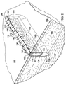
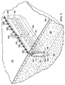
図1および2を参照すると、説明に役立つ実施形態による患者の組織部位102に減圧を加える減圧治療システム100が示されている。減圧治療システム100は、真皮106を通って組織部位102における筋膜層または皮下組織107まで延在する切開創104に、表皮105の切開口103を通して減圧を加える。用語「切開創」は、組織部位において切断された組織、例えば、外傷、手術、または変性を原因とし得る裂傷、切開、または穿刺などを指す。例えば、切開創は、外科医によって、本来健康な組織に行われる、長さが40cm以上まで延びる切開または穿刺とし得る。この意味では、切開創104は実質的に長くて狭い形状、細長い形状であり、その長さは、切開創104の長手方向軸を表す。切開創は、異なる深さで延びてもよいし(15cm以上まで延びる)、または組織型および切り口の原因に依存して皮下にあってもよい。深さは、切開創104の横軸を表す。切開創104は、組織部位102において切開口103に隣接した組織で取り囲まれ、かつ切開壁108および109によって形成される。切開創104を組織部位102における表皮の切り口として示すが、切開創104はまた、例えば、瘻孔に隣接した器官における切り口とし得る。1つ以上の筋膜層または皮下組織107に皮下用の吸収性縫合糸(図示せず)を配置してもよい。
With reference to FIGS. 1 and 2, a reduced
システム100は、フィルター(図示せず)を備えるキャニスター110と、第1の導管111を介してキャニスター110に流体連通して結合されている減圧源112とを含む。システム100は、切開創104内において切開壁108と109との間で位置決めされる足場114をさらに含む。足場114は、切開創104の切開口103に隣接して位置決めされる上縁部分124と、下縁部分125と、切開創104の切開壁109および108の面にそれぞれ隣接して位置決めされる、対向する境界面145および147とを含む。足場114は、第2の導管113を介して、キャニスター110を通して減圧源112と流体連通して結合され、第2の導管は、導管コネクタ115によって足場114に流体結合している。システム100はまた、第3の導管117を介して足場114に、直接(図示せず)または第2の導管113を通して間接的にのいずれかで、流体連通して結合された流体供給装置116を含んで、組織部位102における切開創104へ流体118を供給してもよい。
The
減圧源112は電動真空ポンプである。別の実装例では、その代りに、減圧源112を、電力を必要としない、手動によって作動されるまたは手動で充電されるポンプとし得る。減圧源112を任意の他のタイプの減圧ポンプ、または、例えば病院や他の医療施設で利用可能なものなどの壁面吸い込みポートとし得る。減圧源112は、減圧治療ユニット120内に収容されても、またはそれと共に使用されてもよく、減圧治療ユニットはまた、処理装置、センサー、アラームインジケータ、メモリ、データベース、ソフトウェア、表示装置、およびユーザインターフェースを含んでもよく、それらは組織部位102へ減圧治療を行うことをさらに容易にする。一例では、減圧源112にまたはその付近にセンサーまたはスイッチ(図示せず)が配置されて、減圧源112によって生成される圧力を決定し得る。センサーは、減圧源112によって供給される減圧を監視して制御する処理装置(図示せず)と通信し得る。キャニスター110は、組織部位102から除去された滲出液および他の流体をフィルタリングまたは保持するための液溜め、または収集部材とし得る。一実施形態では、キャニスター110および減圧源112は、単一の収容構造に組み込まれる。
The
流体供給装置116を使用して、切開創104用の足場114へ増殖剤および/または修復剤を供給してもよく、増殖剤および/または修復剤は、限定するものではないが、抗菌剤、抗ウィルス剤、細胞成長促進剤、潅注流体、または他の化学的活性剤を含む。システム100は、第3の導管117に位置決めされて足場114への流体118の流量を制御する第1の弁127、および、第2の導管113と第3の導管117との間の接合部と、減圧源112との間で第2の導管113に位置決めされて、減圧流を制御する第2の弁123をさらに含む。減圧治療ユニット120の処理装置は、第1および第2の弁127、123に動作可能に接続されて、患者に施されている特定の療法に必要とされる通り、流体供給装置116から足場114への減圧および/または流体の供給をそれぞれ制御する。流体供給装置116は、上述の通り流体を供給し得るが、同様に足場114に空気を供給して治癒を促し、かつ切開創104のドレナージを容易にする。流体118は気体でも液体でもよく、かつ、組織部位102における切開創104を治療するために成長因子、治癒促進因子(healing factor)、または他の物質を含有し得る。例えば、流体118は、水、生理食塩水、または着色生理食塩水(dye saline)とし得る。
The
本明細書では、用語「足場」は、細胞増殖および/または組織形成のための構造マトリックスを提供する、創傷または欠損に適用または位置決めされる物体または構造を指す。足場は、特定の創傷欠損の形状にほぼ対応する寸法を有する三次元多孔質構造である。足場114は、細胞、成長因子、細胞外マトリックス成分、栄養素、タンパク質、または他の物質が注入され、それらで被覆され、またはそれらで構成されて、細胞増殖を促進し得る。足場114は、その構造マトリックスを流れるように流体を方向付けることによってマニホールドの特徴を有し得る。例えば、足場114は、組織部位へ減圧を方向付けることによって、または流体を供給する、または組織部位から流体を除去することによって、マニホールドの特徴を呈し得る。本明細書では、用語「マニホールド」は、組織部位に減圧を方向付ける、組織部位に流体を供給する、または組織部位から流体を除去するのを支援するために設けられる物体または構造を指す。マニホールドは、複数の流路または流れ経路を含み、それら流路または流れ経路は相互に接続されて、マニホールド周囲の組織部位への流体の提供およびその組織部位からの流体の除去の分配を改善することができる。マニホールドの例は、限定するものではないが、流路を形成するように配置された構造要素を有する装置、セル状発泡体、例えば、連続気泡発泡体、多孔性組織集合体、液体、ゲル、および流路を含むまたは硬化して流路を含む発泡体などを含み得る。足場114は、上述のようなマニホールドの特徴を有する。
As used herein, the term “scaffold” refers to an object or structure applied or positioned to a wound or defect that provides a structural matrix for cell growth and / or tissue formation. A scaffold is a three-dimensional porous structure having dimensions that roughly correspond to the shape of a particular wound defect. The
足場114は、組織の修復および再生のためのタンパク質付着および細胞内への成長を支援するのに使用される生物学的足場または合成足場とし得る。足場技術における当業界の現在の状態は、タンパク質吸着および細胞移動のための周囲組織空間の固有の特徴に依存している。本発明に従って用いるための足場114は、マニホールドとしての機能と併せて、切開創104内で流体の流れ経路を方向付けるための物理的な誘導を提供し、それぞれ接着タンパク質および細胞の動きおよび移動の道を形成する。これらは、組織空間内で予め定められたパターンの構成での仮マトリックスの確立に不可欠である。流体の流れによって誘発された組織の生成に関して説明した方法および装置は、足場114の設計に直接関係する。ある面において、足場114は、生物学的吸収特性を改善するために空隙比の高い網状構造、例えば、網状発泡体などとし得る。
The
好適な足場材料の非限定的な例は、細胞外マトリックスタンパク質、例えばフィブリン、コラーゲンまたはフィブロネクチン、および合成高分子または天然高分子(生体吸収性または非生体吸収性高分子を含む)、例えばポリ乳酸(PLA)、ポリグリコール酸(PGA)、ポリラクチド−コ−グリコリド(polylactide−co−glycolide)(PLGA)、ポリビニルピロリドン、ポリカプロラクトン、ポリカーボネート、ポリフマレート、カプロラクトン、ポリアミド、多糖類(アルギン酸(例えば、アルギン酸カルシウム)およびキトサンを含む)、ヒアルロン酸、ポリヒドロキシ酪酸、ポリヒドロキシ吉草酸、ポリジオキサノン、ポリエチレングリコール、ポロキサマー、ポリホスファゼン(polyphosphazene)、ポリ無水物、ポリアミノ酸、ポリオルソエステル(polyortho ester)、ポリアセタール、ポリシアノアクリレート、ポリウレタン、ポリアクリレート、エチレン酢酸ビニルポリマーおよび他のアシル置換酢酸セルロースおよびその誘導体、ポリスチレン、ポリ塩化ビニル、ポリフッ化ビニル、ポリ(ビニルイミダゾール)、クロロスルホン化ボリオレフィン、ポリエチレンオキシド、ポリビニルアルコール、Teflon(登録商標)、およびナイロンを含む。足場114はまた、セラミクス、例えばヒドロキシアパタイト、珊瑚アパタイト(coralline apatite)、リン酸カルシウム、硫酸カルシウム、炭酸カルシウムまたは他のカーボネート、バイオガラス、同種移植片、自家移植片、異種移植片、脱細胞化(decellularized)組織、または上述のいずれかの複合材を含み得る。特定の実施形態では、足場114は、コラーゲン、ポリ乳酸(PLA)、ポリグリコール酸(PGA)、ポリラクチド−コ−グリコリド(PLGA)、ポリウレタン、多糖、ヒドロキシアパタイト、またはポリテリレングリコールを含む。加えて、足場114は、足場114の別個の部位に、任意の2種、3種またはそれ以上の物質の組み合わせ、または非共有または共有の組み合わせ(例えば、ポリエチレンオキシド−ポリプロピレングリコールブロック共重合体などの共重合体、または三元共重合体)、またはこれらの組み合わせを含んでもよい。
Non-limiting examples of suitable scaffold materials include extracellular matrix proteins such as fibrin, collagen or fibronectin, and synthetic or natural polymers (including bioabsorbable or non-bioabsorbable polymers) such as polylactic acid (PLA), polyglycolic acid (PGA), polylactide-co-glycolide (PLGA), polyvinylpyrrolidone, polycaprolactone, polycarbonate, polyfumarate, caprolactone, polyamide, polysaccharide (alginate (eg, calcium alginate) ) And chitosan), hyaluronic acid, polyhydroxybutyric acid, polyhydroxyvaleric acid, polydioxanone, polyethylene glycol, poloxamer, polyphosphazene azene), polyanhydrides, polyamino acids, polyorthoesters, polyacetals, polycyanoacrylates, polyurethanes, polyacrylates, ethylene vinyl acetate polymers and other acyl substituted cellulose acetates and derivatives thereof, polystyrene, polyvinyl chloride, Polyvinyl fluoride, poly (vinyl imidazole), chlorosulfonated polyolefin, polyethylene oxide, polyvinyl alcohol, Teflon®, and nylon.
一実施形態では、足場114は、フェルト化プロセスによって形成されたPLGA繊維を含む足場材料から形成され、このPLGA繊維も、上述のようなマニホールドとして機能する。Scaftex(商標)として公知のそのような材料は、Biomedical Structures,Incから入手できる。網状でありかつ空隙比の高い(分解または吸収のための低質量)、上述の生物分解性または生物再吸収性材料のいずれかを使用し得る。切開創104などの軟組織応用に好ましい実施形態は、エラストマー材料、柔軟な材料、およびゲルである。足場114は、切開創104の切開壁109、108にそれぞれ隣接して位置決めされる対向する境界面145と147との間において比較的薄い。非限定的な一例では、足場114の対向する境界面145と147との間の厚みは、約0.25mm〜3.0mmとし得る。足場114の厚みを切開創104の長さおよび深さと比較すると、足場114を比較的薄いと説明し得る。一実施形態では、足場114の長さ対厚さの比は約10を上回る。好ましくは、足場114は、切開創104内に適合するために可能な限り薄くし、切開壁108と109との間の距離を最小にして組織付着を容易にする必要がある。足場114は十分に薄いが、足場114を形成する材料は、依然として経路のマトリックス(図示せず)を含み、切開壁108と109との間を容易に流体が流れるようにする。足場114のこれらの経路は、対向する境界面145と147との間で足場114に広がっており、切開創104内の境界面足場マトリックスとして切開壁108と109との間での組織の増殖を促進することにより、組織付着を誘発する。
In one embodiment, the
足場114は、例えば、切開創104のタイプおよびサイズ、および創傷を修復するために施されている治療のタイプなど、様々な要因に依存して任意のサイズまたは形状とし得る。例えば、足場114は実質的に矩形とし、長手方向軸に沿って切開創104の全長および横軸に沿って切開壁108、109の深さ全体に延在し得る。そのような寸法の足場114は、2つの切開壁108と109との間に全境界面足場マトリックスを形成し、それら2つの壁の間に組織付着を誘発する。しかしながら、治療に応じて、足場114は切開壁108、109に部分的にのみ接触する。例えば、足場114は、切開創104の底部まで延在せず、皮下組織107に及ばない可能性がある。足場114の上縁部分124は、表皮105に隣接する切開創104の切開口103と同一平面に位置決めされ、かつ、縫合時に切開創104を閉じる複数の縫合糸130によって切開創104内に固定される。
The
足場114は、足場114内に既に存在する網状経路を通る流体の流れを補う内部マニホールド構造140をさらに含み得る。内部マニホールド構造140は、導管コネクタ115に流体結合された1つまたは複数の主流路141を含み、主流路は、切開壁108と109との間で足場114にわたって全体的に長手方向に延在し得る。内部マニホールド構造140はまた、主流路141の1つ以上に流体結合された追加的な支流路143を含み得る。支流路143は、対向する境界面145と147との間で足場114内を全体的に横方向に延在して、切開創104内の境界面足場マトリックスの大きな領域にわたる流体の流れをさらに促進する。支流路143は、主流路141から、主流路141に対して任意の方向で延在し、かつ境界面145、147を含む足場114の領域を強化するように任意の形状を形成し得る。例えば、特定の非限定的な実施形態で示すように、支流路143は、湾曲形状を有するのとは対照的に、主流路141からほぼ垂直な方向に、直線方向に延在する。それゆえ、内部マニホールド構造140は、複数の主流路141、または複数の支流路143を含み得る単一の主流路、またはそれら双方の組み合わせを使用することにより、足場114の網状経路と同一の広がりを有する流体の流れ用の補足マトリックスを提供する。内部マニホールド構造140のこの補足マトリックスは、切開壁108、109の付着をさらに誘発するパターンで形成され得る。
The
主流路141は、図面ではほぼチューブ状形状であるとして示すが、そのような流路が切開壁108と109との間で足場114全体に全体的に長手方向に延在する限り、主流路141は様々な異なる形状とし得る。主流路141は直線である必要はなく、足場114内において上縁部分124と下縁部分125との間で長手方向に波状であってもよい。主流路141はまた、切開壁108と109との間で全体的に長手方向に延在する、足場114自体の異方性の材料特性とし得る。例えば、異方特性は、足場114の全体的に長手方向軸に沿って延在する、足場114内の互いにつながった細孔を通る流体の流れに対する差動抵抗(differential resistance)とし得る。異方特性はまた、足場114内の細孔の整列および細孔の相互接続性、または足場114の長手方向軸に沿った流体の流れを可能にまたは容易にする足場114内での細孔の大きさの変動とし得る。別の実施形態では、主流路141は、生物再吸収性チューブによって形成し得る。
Although the
支流路143は、形状が非対称的であり、かつ足場114の異方特性によって形成し得る。別の実施形態では、支流路143は、生物再吸収性チューブによって形成し得る。支流路143の入口は、主流路141の表面から延在しているように示しているが、支流路143はまた、主流路141内部の各場所から延在して、非平行の非対称的な流路として足場114内で分岐し得る。そのような支流路143の入口は、主流路141と流体連通して、切開壁108と109との間の流体の流れを促進する。いくつかの支流路143の入口はまた、主流路141内の単一の場所から生じ、例えば、切開壁108と109との間で、切開壁に全体的に平行に星型パターンに分岐する。
The
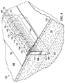
図3を参照すると、足場114は、足場114の上縁部分124が表皮105の下側に置かれるように切開創104内に位置決めされ、縫合糸230を使用して、切開創104内に足場114全体を閉じ込めるようにし得る。足場114の上縁部分124を切開創104の表皮105の下側に置くことによって、切開創104の切開口103の閉鎖を容易にし、かつ、切開創104内に、より長時間減圧を維持することを助け得る。図2に戻ると、代替的な実施形態(図示せず)では、足場114の上縁部分124は、表皮105の上方に切開口103から突出しているので、縫合糸130で、足場114の上部を通して縫い、切開創104内の適所に足場をしっかりと保持するようにする。この実施形態では、縫合糸130でまた、創傷の切開口103を実質的に閉鎖するように十分に密に縫われ、上述の治癒をさらに促進し得る。
Referring to FIG. 3, the
図4に示す別の実施形態では、足場114は、切開創104内に閉じ込められているのとは対照的に、表皮105の切開口103から露出され得る。この実施形態では、システム100は、足場114と流体連通する外部マニホールド150と、外部マニホールド150を覆うドレープ152とをさらに含み、ドレープは、切開創104内のドレープ152の下側における減圧を維持し得る。ドレープ152はアパーチャ153を含み、そのアパーチャを通って導管コネクタ115が延在し、第2の導管113と外部マニホールド150との間を流体連通させる。ドレープ152はまた、切開口103を越えて延在する周囲部分154も含み、周囲部分は接着剤または結合剤(図示せず)を含んで、切開口103に隣接する健康な組織にドレープ152を固定し得る。接着剤は、ドレープ152と表皮105との間にシールを提供し、切開創104内の減圧をより良好に維持する。別の実施形態では、例えば、ヒドロゲルまたは他の材料などのシール層(図示せず)を、ドレープ152と表皮105との間に配置して、接着剤のシール性を増強する、またはその代わりとする。ドレープ152はまた、上述の図2および図3に示す実施形態と併せて使用し得る。
In another embodiment shown in FIG. 4, the
ドレープ152は、空気シールまたは流体シールをもたらす任意の材料とし得る。ドレープ152は、例えば、不浸透性または半透過性のエラストマー材料とし得る。上述の通り、ドレープ152は、周囲部分154に接着剤層を含み得る。
The
上記を考慮して、本発明の利点を達成しかつ他の利点を得られることが分かる。本発明の範囲から逸脱せずに、上述の方法および構成に様々な変更をなすことができるため、上記の説明に含まれ、かつ添付図面に示される全ての事柄は、限定ではなく、例示であると解釈されるものとする。 In view of the above, it will be seen that the advantages of the invention are achieved and other advantages attained. Since various modifications can be made to the above methods and configurations without departing from the scope of the invention, all matter contained in the above description and shown in the accompanying drawings is illustrative and not restrictive. It shall be interpreted as being.
上述の利益および利点は、一実施形態に関係し得ること、またはいくつかの実施形態に関係し得ることを理解されたい。「1つの」品目への言及は、それら品目の1つ以上を指すことをさらに理解されたい。 It should be understood that the benefits and advantages described above may relate to one embodiment or may relate to several embodiments. It is further understood that reference to “a” item refers to one or more of those items.
適切な場合には、上述のいずれかの例および実施形態の態様を、上述の他のいずれかの例の態様と組み合わせて、類似のまたは異なる特性を有しかつ同じまたは異なる問題に対処する別の例を形成する。 Where appropriate, aspects of any of the examples and embodiments described above may be combined with aspects of any other examples described above to have similar or different characteristics and address the same or different issues. Form an example.
好ましい実施形態の上述の説明は、一例としてのみ与えられること、および、様々な修正を当業者がなし得ることを理解されたい。上記の明細書、例およびデータは、本発明の例示的な実施形態の構造および使用の完全な説明を提供する。本発明の様々な実施形態をある程度詳細に、または1つ以上の個別の実施形態を参照して上記で説明したが、当業者は、特許請求の範囲から逸脱せずに、開示の実施形態に多数の修正をなし得る。 It should be understood that the above description of the preferred embodiments is given by way of example only and that various modifications can be made by those skilled in the art. The above specification, examples and data provide a complete description of the structure and use of exemplary embodiments of the invention. Although various embodiments of the present invention have been described above in some detail or with reference to one or more individual embodiments, those skilled in the art will recognize that the disclosed embodiments can be practiced without departing from the scope of the claims. Many modifications can be made.
Claims (58)
減圧を受ける第1の端部と、第2の端部とを有する導管;
前記切開壁に隣接して位置決めするための対向面を有し、かつ減圧を受けるために前記導管の前記第2の端部に流体結合されている足場において、前記足場が全体的に細長い形状であり、かつ前記対向面間の足場の厚さが、前記切開創内に位置決めされるのに十分な程度薄い、足場;および
前記足場内において前記対向面間で全体的に長手方向に延在する主流路を有し、かつ前記導管の前記第2の端部に流体結合されている内部マニホールド;
を含み、
それにより、前記足場および前記内部マニホールドを通して減圧を行うことによって、前記切開壁間に組織付着が誘発されることを特徴とする装置。 A device for treating an incision having an incision wall,
A conduit having a first end subject to reduced pressure and a second end;
In a scaffold having an opposing surface for positioning adjacent to the incision wall and fluidly coupled to the second end of the conduit to receive reduced pressure, the scaffold is generally elongated. And the scaffold between the opposing surfaces is thin enough to be positioned within the incision; and a scaffold extending generally longitudinally between the opposing surfaces within the scaffold; An internal manifold having a main flow path and fluidly coupled to the second end of the conduit;
Including
Thereby, tissue attachment is induced between the incision walls by applying a vacuum through the scaffold and the internal manifold.
前記足場の一部分と流体結合している外部マニホールド;および
実質的に不浸透性材料から形成され、前記外部マニホールドおよび前記切開創内の前記足場を覆うドレープ
をさらに含むことを特徴とする装置。 The apparatus of claim 1.
An apparatus comprising: an outer manifold fluidly coupled to a portion of the scaffold; and a drape formed from a substantially impermeable material and covering the outer manifold and the scaffold within the incision.
減圧を供給するための圧力源;
前記圧力源に流体結合され、減圧を受ける第1の端部と、第2の端部とを有する導管;
減圧を受けるために前記導管の前記第2の端部に流体結合され、かつ前記切開壁に隣接して前記切開創内に位置決めするための対向面を有する足場において、前記切開創内に位置決めするために、全体的に細長い形状の多孔質材料から形成される足場;および
前記足場内において前記対向面間で全体的に長手方向に延在しかつ前記導管の前記第2の端部に流体結合されている主流路を有する内部マニホールド;
を含み、
それにより、前記足場および前記内部マニホールドを通して減圧を行うことによって、前記切開壁間に組織付着を誘発することを特徴とするシステム。 A system for treating an incision having an incision wall,
Pressure source for supplying reduced pressure;
A conduit fluidly coupled to the pressure source and having a first end for receiving reduced pressure and a second end;
Positioning in the incision in a scaffold fluidly coupled to the second end of the conduit to receive reduced pressure and having an opposing surface for positioning in the incision adjacent to the incision wall A scaffold formed of a generally elongate shaped porous material; and within the scaffold, extending generally longitudinally between the opposing surfaces and fluidly coupled to the second end of the conduit An internal manifold having a main flow path;
Including
Thereby inducing tissue attachment between the incision walls by applying a vacuum through the scaffold and the internal manifold.
前記足場の一部分と流体結合している外部マニホールド;および
実質的に不浸透性材料で形成され、前記外部マニホールドおよび前記切開創内の前記足場を覆うドレープ
をさらに含むことを特徴とするシステム。 The system of claim 21, wherein
An external manifold fluidly coupled to a portion of the scaffold; and a drape formed of a substantially impervious material and covering the external manifold and the scaffold within the incision.
減圧を供給するための圧力源;
前記圧力源に流体結合され、減圧を受ける第1の端部と、第2の端部とを有する導管;
減圧を受けるために前記導管の前記第2の端部に流体結合され、かつ前記切開創内で前記切開壁に隣接して位置決めするための対向面を有する足場において、前記足場は、前記切開創内に位置決めするために、全体的に細長い形状の多孔質材料から形成され、前記足場の厚さは約0.25mm超かつ約3.0mm未満である、足場;および
内部マニホールドであって:
前記足場内において前記対向面間で全体的に長手方向に延在し、かつ前記導管の前記第2の端部に流体結合されている主流路と;
前記主流路に流体結合され、かつ前記足場内において前記対向面間で延在する支流路において、前記主流路からほぼ垂直に延在している支流路と
を含む内部マニホールド
を含み、
それにより、前記足場および前記内部マニホールドを通して減圧を行うことによって、前記切開壁間に組織付着を誘発することを特徴とするシステム。 A system for treating an incision having an incision wall,
Pressure source for supplying reduced pressure;
A conduit fluidly coupled to the pressure source and having a first end for receiving reduced pressure and a second end;
A scaffold that is fluidly coupled to the second end of the conduit to receive reduced pressure and has an opposing surface for positioning adjacent to the incision wall within the incision, the scaffold comprising the incision A scaffold formed from a generally elongate shaped porous material for positioning within, the scaffold thickness being greater than about 0.25 mm and less than about 3.0 mm; and an internal manifold:
A main flow path extending generally longitudinally between the opposing surfaces within the scaffold and fluidly coupled to the second end of the conduit;
An internal manifold including a branch channel that is fluidly coupled to the main channel and extends between the opposing surfaces in the scaffold, and a branch channel that extends substantially perpendicularly from the main channel;
Thereby inducing tissue attachment between the incision walls by applying a vacuum through the scaffold and the internal manifold.
前記足場の一部分と流体結合している外部マニホールド;および
実質的に不浸透性材料で形成され、前記外部マニホールドおよび前記切開創内の前記足場を覆うドレープ
をさらに含むことを特徴とするシステム。 36. The system of claim 35.
An external manifold fluidly coupled to a portion of the scaffold; and a drape formed of a substantially impervious material and covering the external manifold and the scaffold within the incision.
前記切開壁に隣接して位置決めするための対向面を有する足場において、前記足場が全体的に細長い形状であり、および前記対向面間の足場の厚さが、前記切開創内に位置決めするために十分な程度薄い、足場;および
減圧源に流体結合するために、前記足場内において前記対向面間で全体的に長手方向に延在する主流路を有する内部マニホールド
を含むことを特徴とする装置。 A device for treating an incision having an incision wall,
In a scaffold having opposing surfaces for positioning adjacent to the incision wall, the scaffold is generally elongate and the thickness of the scaffold between the opposing surfaces is positioned within the incision An apparatus comprising an internal manifold having a main flow path extending generally longitudinally between said opposing surfaces within said scaffold for fluid coupling to a reduced pressure source;
前記足場の一部分と流体結合している外部マニホールド;および
実質的に不浸透性材料で形成され、前記外部マニホールドおよび前記切開創内の前記足場を覆うドレープ
をさらに含むことを特徴とする装置。 The apparatus according to any one of claims 37 to 55,
An external manifold fluidly coupled to a portion of the scaffold; and a drape formed of a substantially impervious material and covering the external manifold and the scaffold within the incision.
Applications Claiming Priority (5)
| Application Number | Priority Date | Filing Date | Title |
|---|---|---|---|
| US32976410P | 2010-04-30 | 2010-04-30 | |
| US61/329,764 | 2010-04-30 | ||
| US13/095,384 US8623047B2 (en) | 2010-04-30 | 2011-04-27 | System and method for sealing an incisional wound |
| US13/095,384 | 2011-04-27 | ||
| PCT/US2011/034300 WO2011137230A1 (en) | 2010-04-30 | 2011-04-28 | System and method for sealing an incisional wound |
Publications (3)
| Publication Number | Publication Date |
|---|---|
| JP2013525031A JP2013525031A (en) | 2013-06-20 |
| JP2013525031A5 JP2013525031A5 (en) | 2014-06-19 |
| JP5999713B2 true JP5999713B2 (en) | 2016-09-28 |
Family
ID=44858862
Family Applications (1)
| Application Number | Title | Priority Date | Filing Date |
|---|---|---|---|
| JP2013508247A Expired - Fee Related JP5999713B2 (en) | 2010-04-30 | 2011-04-28 | System and method for closing an incision |
Country Status (8)
| Country | Link |
|---|---|
| US (4) | US8623047B2 (en) |
| EP (2) | EP2563421B1 (en) |
| JP (1) | JP5999713B2 (en) |
| CN (1) | CN102858384B (en) |
| AU (1) | AU2011245310B2 (en) |
| CA (1) | CA2792240C (en) |
| TW (1) | TW201141434A (en) |
| WO (1) | WO2011137230A1 (en) |
Families Citing this family (89)
| Publication number | Priority date | Publication date | Assignee | Title |
|---|---|---|---|---|
| US20050182443A1 (en) | 2004-02-18 | 2005-08-18 | Closure Medical Corporation | Adhesive-containing wound closure device and method |
| US20060009099A1 (en) | 2004-07-12 | 2006-01-12 | Closure Medical Corporation | Adhesive-containing wound closure device and method |
| US9820888B2 (en) | 2006-09-26 | 2017-11-21 | Smith & Nephew, Inc. | Wound dressing |
| GB0804654D0 (en) | 2008-03-13 | 2008-04-16 | Smith & Nephew | Vacuum closure device |
| EP2515961B1 (en) | 2009-12-22 | 2019-04-17 | Smith & Nephew, Inc. | Apparatuses for negative pressure wound therapy |
| US8623047B2 (en) * | 2010-04-30 | 2014-01-07 | Kci Licensing, Inc. | System and method for sealing an incisional wound |
| EP2441409A1 (en) | 2010-10-12 | 2012-04-18 | Smith&Nephew, Inc. | Medical device |
| US9050398B2 (en) * | 2010-12-22 | 2015-06-09 | Smith & Nephew, Inc. | Apparatuses and methods for negative pressure wound therapy |
| CN106974683B (en) | 2011-02-04 | 2020-02-21 | 马萨诸塞州大学 | Negative pressure wound closure device |
| US9421132B2 (en) | 2011-02-04 | 2016-08-23 | University Of Massachusetts | Negative pressure wound closure device |
| WO2012142473A1 (en) | 2011-04-15 | 2012-10-18 | University Of Massachusetts | Surgical cavity drainage and closure system |
| BR112014001112A2 (en) * | 2011-07-19 | 2019-04-02 | Shieldheart Medtech Ab | stabilizer for stabilizing the position of a wound dressing and / or barrier disc; barrier disc or wound dressing for use in treating a wound; method for controlling the position of a wound dressing or barrier disc in therapy for negative pressure injuries; method for maintaining or facilitating wound pressure transduction or drainage from a wound dressing or barrier disc in negative pressure wound treatment |
| WO2013136181A2 (en) | 2012-03-12 | 2013-09-19 | Smith & Nephew Plc | Reduced pressure apparatus and methods |
| US9161756B2 (en) * | 2012-03-16 | 2015-10-20 | Covidien Lp | Closure tape dispenser |
| WO2013175310A2 (en) | 2012-05-22 | 2013-11-28 | Smith & Nephew Plc | Apparatuses and methods for wound therapy |
| CA2874396A1 (en) | 2012-05-22 | 2014-01-23 | Smith & Nephew Plc | Wound closure device |
| CA2874581C (en) | 2012-05-24 | 2022-06-07 | Smith & Nephew Inc. | Devices and methods for treating and closing wounds with negative pressure |
| AU2013290346B2 (en) | 2012-07-16 | 2018-06-07 | Smith & Nephew, Inc. | Negative pressure wound closure device |
| MX365816B (en) * | 2012-09-20 | 2019-06-13 | Lohmann & Rauscher Gmbh | Vacuum treatment array and film for producing a vacuum treatment array. |
| CN104736091A (en) * | 2012-09-21 | 2015-06-24 | 3M创新有限公司 | Incision protection |
| DE102013002521A1 (en) * | 2013-02-13 | 2014-08-14 | Paul Hartmann Ag | Abdominal wound pad with lanyard |
| DE102013002497A1 (en) * | 2013-02-13 | 2014-08-14 | Paul Hartmann Ag | Bandage kit for the treatment of wound cavities |
| EP2968016B1 (en) | 2013-03-13 | 2018-07-11 | Smith&Nephew, Inc. | Negative pressure wound closure device and systems and methods of use in treating wounds with negative pressure |
| AU2014236701B2 (en) | 2013-03-14 | 2018-07-19 | Smith & Nephew Inc. | Systems and methods for applying reduced pressure therapy |
| US10159771B2 (en) | 2013-03-14 | 2018-12-25 | Smith & Nephew Plc | Compressible wound fillers and systems and methods of use in treating wounds with negative pressure |
| US9737649B2 (en) | 2013-03-14 | 2017-08-22 | Smith & Nephew, Inc. | Systems and methods for applying reduced pressure therapy |
| CA2901882C (en) * | 2013-03-14 | 2021-04-13 | Kci Licensing, Inc. | Micro-porous conduit |
| US9408955B2 (en) | 2013-03-15 | 2016-08-09 | Acclarent, Inc. | Nasal fluid management device |
| US9408756B2 (en) | 2013-03-15 | 2016-08-09 | Acclarent, Inc. | Nasal fluid management device |
| US9604041B2 (en) | 2013-03-15 | 2017-03-28 | Acclarent, Inc. | Nasal fluid management device |
| AU2014291873B2 (en) | 2013-07-16 | 2019-01-24 | Smith & Nephew Plc | Apparatus for wound therapy |
| CA2920850C (en) | 2013-08-13 | 2022-08-30 | Smith & Nephew, Inc. | Systems and methods for applying reduced pressure therapy |
| JP6723917B2 (en) | 2013-10-21 | 2020-07-15 | スミス アンド ネフュー インコーポレイテッド | Negative pressure wound closure device |
| US10179073B2 (en) | 2014-01-21 | 2019-01-15 | Smith & Nephew Plc | Wound treatment apparatuses |
| JP6742908B2 (en) | 2014-01-21 | 2020-08-19 | スミス アンド ネフュー ピーエルシーSmith & Nephew Public Limited Company | Crushable negative pressure wound dressing |
| EP3190998A4 (en) * | 2014-07-28 | 2018-03-28 | Bioceptive, Inc. | Device and methods for manipulating a uterus or other bodily tissue |
| US9770369B2 (en) | 2014-08-08 | 2017-09-26 | Neogenix, Llc | Wound care devices, apparatus, and treatment methods |
| USD824525S1 (en) | 2014-09-25 | 2018-07-31 | Ethicon Llc | Release paper for wound treament devices |
| CN113367890B (en) | 2015-04-27 | 2023-02-21 | 史密夫及内修公开有限公司 | Pressure reducing device |
| EP3288509B1 (en) | 2015-04-29 | 2022-06-29 | Smith & Nephew, Inc | Negative pressure wound closure device |
| CN105169499A (en) * | 2015-07-11 | 2015-12-23 | 赵全明 | Closed washing and drainage apparatus for osteomyelitis treatment |
| WO2017019939A1 (en) | 2015-07-29 | 2017-02-02 | Innovative Therapies, Inc. | Wound therapy device pressure monitoring and control system |
| AU2015411394B2 (en) | 2015-10-07 | 2021-07-08 | Smith & Nephew, Inc. | Systems and methods for applying reduced pressure therapy |
| US11471586B2 (en) | 2015-12-15 | 2022-10-18 | University Of Massachusetts | Negative pressure wound closure devices and methods |
| US10814049B2 (en) | 2015-12-15 | 2020-10-27 | University Of Massachusetts | Negative pressure wound closure devices and methods |
| US10575991B2 (en) | 2015-12-15 | 2020-03-03 | University Of Massachusetts | Negative pressure wound closure devices and methods |
| AU2017230775B2 (en) | 2016-03-07 | 2021-12-23 | Smith & Nephew Plc | Wound treatment apparatuses and methods with negative pressure source integrated into wound dressing |
| AU2017256692B2 (en) | 2016-04-26 | 2022-03-03 | Smith & Nephew Plc | Wound dressings and methods of use with integrated negative pressure source having a fluid ingress inhibition component |
| WO2017191154A1 (en) | 2016-05-03 | 2017-11-09 | Smith & Nephew Plc | Negative pressure wound therapy device activation and control |
| AU2017259003B2 (en) | 2016-05-03 | 2022-09-22 | Smith & Nephew Plc | Systems and methods for driving negative pressure sources in negative pressure therapy systems |
| WO2017191149A1 (en) | 2016-05-03 | 2017-11-09 | Smith & Nephew Plc | Optimizing power transfer to negative pressure sources in negative pressure therapy systems |
| WO2017197357A1 (en) | 2016-05-13 | 2017-11-16 | Smith & Nephew Plc | Automatic wound coupling detection in negative pressure wound therapy systems |
| CN109561994B (en) | 2016-08-25 | 2022-03-15 | 史密夫及内修公开有限公司 | Absorbent negative pressure wound therapy dressing |
| US11135351B2 (en) | 2016-08-30 | 2021-10-05 | Smith & Nephew Plc | Systems and methods for applying reduced pressure therapy |
| EP3518847B1 (en) | 2016-09-27 | 2023-03-01 | Smith & Nephew plc | Wound closure devices with dissolvable portions |
| US10792024B2 (en) | 2016-09-28 | 2020-10-06 | Ethicon, Inc. | Scaffolds with channels for joining layers of tissue at discrete points |
| US10687986B2 (en) | 2016-09-29 | 2020-06-23 | Ethicon, Inc. | Methods and devices for skin closure |
| US11369730B2 (en) | 2016-09-29 | 2022-06-28 | Smith & Nephew, Inc. | Construction and protection of components in negative pressure wound therapy systems |
| USD848624S1 (en) | 2016-09-29 | 2019-05-14 | Ethicon, Inc. | Release paper for wound treatment devices |
| US10470934B2 (en) | 2016-09-29 | 2019-11-12 | Ethicon, Inc. | Methods and devices for skin closure |
| US11564847B2 (en) | 2016-09-30 | 2023-01-31 | Smith & Nephew Plc | Negative pressure wound treatment apparatuses and methods with integrated electronics |
| WO2018085457A1 (en) | 2016-11-02 | 2018-05-11 | Smith & Nephew Inc. | Wound closure devices |
| JP7063912B2 (en) | 2017-03-07 | 2022-05-09 | スミス アンド ネフュー インコーポレイテッド | Decompression therapy system and method including antenna |
| JP7361606B2 (en) | 2017-03-08 | 2023-10-16 | スミス アンド ネフュー ピーエルシー | Control of negative pressure wound therapy devices in the presence of fault conditions |
| US10470935B2 (en) | 2017-03-23 | 2019-11-12 | Ethicon, Inc. | Skin closure systems and devices of improved flexibility and stretchability for bendable joints |
| US11504446B2 (en) | 2017-04-25 | 2022-11-22 | Ethicon, Inc. | Skin closure devices with self-forming exudate drainage channels |
| JP7121050B2 (en) | 2017-05-09 | 2022-08-17 | スミス アンド ネフュー ピーエルシー | Redundant control of negative pressure wound therapy systems |
| AU2018285236B2 (en) | 2017-06-13 | 2024-02-29 | Smith & Nephew Plc | Wound closure device and method of use |
| US11324876B2 (en) | 2017-06-13 | 2022-05-10 | Smith & Nephew Plc | Collapsible structure and method of use |
| US11583623B2 (en) | 2017-06-14 | 2023-02-21 | Smith & Nephew Plc | Collapsible structure for wound closure and method of use |
| JP2020523052A (en) | 2017-06-14 | 2020-08-06 | スミス アンド ネフュー インコーポレイテッド | Fluid removal management and control of wound closure in wound care |
| JP7419072B2 (en) | 2017-06-14 | 2024-01-22 | スミス アンド ネフュー ピーエルシー | Foldable sheet for wound closure and method of use |
| EP3638173A1 (en) | 2017-06-14 | 2020-04-22 | Smith & Nephew, Inc | Control of wound closure and fluid removal management in wound therapy |
| US11712508B2 (en) | 2017-07-10 | 2023-08-01 | Smith & Nephew, Inc. | Systems and methods for directly interacting with communications module of wound therapy apparatus |
| EP3658090B1 (en) * | 2017-07-27 | 2021-11-10 | Smith & Nephew PLC | Customizable wound closure device |
| EP3664756B1 (en) | 2017-08-07 | 2024-01-24 | Smith & Nephew plc | Wound closure device with protective layer |
| WO2019042790A1 (en) | 2017-08-29 | 2019-03-07 | Smith & Nephew Plc | Systems and methods for monitoring wound closure |
| GB201718070D0 (en) | 2017-11-01 | 2017-12-13 | Smith & Nephew | Negative pressure wound treatment apparatuses and methods with integrated electronics |
| AU2018331954A1 (en) | 2017-09-13 | 2020-03-19 | Smith & Nephew Plc | Negative pressure wound treatment apparatuses and methods with integrated electronics |
| US11497653B2 (en) | 2017-11-01 | 2022-11-15 | Smith & Nephew Plc | Negative pressure wound treatment apparatuses and methods with integrated electronics |
| GB201718054D0 (en) | 2017-11-01 | 2017-12-13 | Smith & Nephew | Sterilization of integrated negative pressure wound treatment apparatuses and sterilization methods |
| GB201718072D0 (en) | 2017-11-01 | 2017-12-13 | Smith & Nephew | Negative pressure wound treatment apparatuses and methods with integrated electronics |
| GB201811449D0 (en) | 2018-07-12 | 2018-08-29 | Smith & Nephew | Apparatuses and methods for negative pressure wound therapy |
| US10993708B2 (en) | 2018-07-31 | 2021-05-04 | Ethicon, Inc. | Skin closure devices with interrupted closure |
| USD898925S1 (en) | 2018-09-13 | 2020-10-13 | Smith & Nephew Plc | Medical dressing |
| GB201820668D0 (en) | 2018-12-19 | 2019-01-30 | Smith & Nephew Inc | Systems and methods for delivering prescribed wound therapy |
| RU194086U1 (en) * | 2019-02-18 | 2019-11-28 | Ирейхан Магамедовна Таджибова | DEVICE FOR CLOSING THE REGIONS OF THE RAS |
| AU2021385936A1 (en) * | 2020-11-24 | 2023-07-13 | Aroa Biosurgery Limited | Fluid drainage and delivery device for wound treatment |
| US20220379004A1 (en) * | 2021-05-26 | 2022-12-01 | Tennessee Technological University | Drug assisted wound drainage line |
Family Cites Families (258)
| Publication number | Priority date | Publication date | Assignee | Title |
|---|---|---|---|---|
| US1195430A (en) | 1916-08-22 | Reinforced tape | ||
| US1355846A (en) | 1920-02-06 | 1920-10-19 | David A Rannells | Medical appliance |
| US1845630A (en) | 1929-02-16 | 1932-02-16 | William M Scholl | Medical dressing |
| US2452345A (en) | 1947-02-12 | 1948-10-26 | Anselmo Ceyl | Brassiere |
| US2547758A (en) | 1949-01-05 | 1951-04-03 | Wilmer B Keeling | Instrument for treating the male urethra |
| US2632443A (en) | 1949-04-18 | 1953-03-24 | Eleanor P Lesher | Surgical dressing |
| GB692578A (en) | 1949-09-13 | 1953-06-10 | Minnesota Mining & Mfg | Improvements in or relating to drape sheets for surgical use |
| US2682873A (en) | 1952-07-30 | 1954-07-06 | Johnson & Johnson | General purpose protective dressing |
| NL189176B (en) | 1956-07-13 | 1900-01-01 | Hisamitsu Pharmaceutical Co | PLASTER BASED ON A SYNTHETIC RUBBER. |
| FR1163907A (en) | 1956-10-25 | 1958-10-02 | Skin care devices | |
| US2969057A (en) | 1957-11-04 | 1961-01-24 | Brady Co W H | Nematodic swab |
| US3026874A (en) | 1959-11-06 | 1962-03-27 | Robert C Stevens | Wound shield |
| US3066672A (en) | 1960-09-27 | 1962-12-04 | Jr William H Crosby | Method and apparatus for serial sampling of intestinal juice |
| US3367332A (en) | 1965-08-27 | 1968-02-06 | Gen Electric | Product and process for establishing a sterile area of skin |
| US3419006A (en) | 1966-08-08 | 1968-12-31 | Union Carbide Corp | Novel dressing and use thereof |
| US3520300A (en) | 1967-03-15 | 1970-07-14 | Amp Inc | Surgical sponge and suction device |
| US3568675A (en) | 1968-08-30 | 1971-03-09 | Clyde B Harvey | Fistula and penetrating wound dressing |
| US3682180A (en) | 1970-06-08 | 1972-08-08 | Coilform Co Inc | Drain clip for surgical drain |
| BE789293Q (en) | 1970-12-07 | 1973-01-15 | Parke Davis & Co | MEDICO-SURGICAL DRESSING FOR BURNS AND SIMILAR LESIONS |
| US3826254A (en) | 1973-02-26 | 1974-07-30 | Verco Ind | Needle or catheter retaining appliance |
| US3892229A (en) | 1973-12-06 | 1975-07-01 | Duane F Taylor | Apparatus for augmenting venous blood flow |
| DE2527706A1 (en) | 1975-06-21 | 1976-12-30 | Hanfried Dr Med Weigand | DEVICE FOR THE INTRODUCTION OF CONTRAST AGENTS INTO AN ARTIFICIAL INTESTINAL OUTLET |
| DE2640413C3 (en) | 1976-09-08 | 1980-03-27 | Richard Wolf Gmbh, 7134 Knittlingen | Catheter monitor |
| NL7710909A (en) | 1976-10-08 | 1978-04-11 | Smith & Nephew | COMPOSITE STRAPS. |
| GB1562244A (en) | 1976-11-11 | 1980-03-05 | Lock P M | Wound dressing materials |
| US4080970A (en) | 1976-11-17 | 1978-03-28 | Miller Thomas J | Post-operative combination dressing and internal drain tube with external shield and tube connector |
| US4091804A (en) | 1976-12-10 | 1978-05-30 | The Kendall Company | Compression sleeve |
| US4139004A (en) | 1977-02-17 | 1979-02-13 | Gonzalez Jr Harry | Bandage apparatus for treating burns |
| US4184510A (en) | 1977-03-15 | 1980-01-22 | Fibra-Sonics, Inc. | Valued device for controlling vacuum in surgery |
| US4165748A (en) | 1977-11-07 | 1979-08-28 | Johnson Melissa C | Catheter tube holder |
| US4245637A (en) | 1978-07-10 | 1981-01-20 | Nichols Robert L | Shutoff valve sleeve |
| US4224945A (en) | 1978-08-30 | 1980-09-30 | Jonathan Cohen | Inflatable expansible surgical pressure dressing |
| SE414994B (en) | 1978-11-28 | 1980-09-01 | Landstingens Inkopscentral | VENKATETERFORBAND |
| GB2047543B (en) | 1978-12-06 | 1983-04-20 | Svedman Paul | Device for treating tissues for example skin |
| US4266545A (en) | 1979-04-06 | 1981-05-12 | Moss James P | Portable suction device for collecting fluids from a closed wound |
| US4284079A (en) | 1979-06-28 | 1981-08-18 | Adair Edwin Lloyd | Method for applying a male incontinence device |
| US4261363A (en) | 1979-11-09 | 1981-04-14 | C. R. Bard, Inc. | Retention clips for body fluid drains |
| US4569348A (en) | 1980-02-22 | 1986-02-11 | Velcro Usa Inc. | Catheter tube holder strap |
| US4480638A (en) | 1980-03-11 | 1984-11-06 | Eduard Schmid | Cushion for holding an element of grafted skin |
| US4297995A (en) | 1980-06-03 | 1981-11-03 | Key Pharmaceuticals, Inc. | Bandage containing attachment post |
| US4375217A (en) | 1980-06-04 | 1983-03-01 | The Kendall Company | Compression device with pressure determination |
| US4333468A (en) | 1980-08-18 | 1982-06-08 | Geist Robert W | Mesentery tube holder apparatus |
| US4465485A (en) | 1981-03-06 | 1984-08-14 | Becton, Dickinson And Company | Suction canister with unitary shut-off valve and filter features |
| US4392853A (en) | 1981-03-16 | 1983-07-12 | Rudolph Muto | Sterile assembly for protecting and fastening an indwelling device |
| US4373519A (en) | 1981-06-26 | 1983-02-15 | Minnesota Mining And Manufacturing Company | Composite wound dressing |
| US4392858A (en) | 1981-07-16 | 1983-07-12 | Sherwood Medical Company | Wound drainage device |
| US4419097A (en) | 1981-07-31 | 1983-12-06 | Rexar Industries, Inc. | Attachment for catheter tube |
| AU550575B2 (en) | 1981-08-07 | 1986-03-27 | Richard Christian Wright | Wound drainage device |
| SE429197B (en) | 1981-10-14 | 1983-08-22 | Frese Nielsen | SAR TREATMENT DEVICE |
| DE3146266A1 (en) | 1981-11-21 | 1983-06-01 | B. Braun Melsungen Ag, 3508 Melsungen | COMBINED DEVICE FOR A MEDICAL SUCTION DRAINAGE |
| US4551139A (en) | 1982-02-08 | 1985-11-05 | Marion Laboratories, Inc. | Method and apparatus for burn wound treatment |
| US4475909A (en) | 1982-05-06 | 1984-10-09 | Eisenberg Melvin I | Male urinary device and method for applying the device |
| DE3361779D1 (en) | 1982-07-06 | 1986-02-20 | Dow Corning | Medical-surgical dressing and a process for the production thereof |
| NZ206837A (en) | 1983-01-27 | 1986-08-08 | Johnson & Johnson Prod Inc | Thin film adhesive dressing:backing material in three sections |
| US4548202A (en) | 1983-06-20 | 1985-10-22 | Ethicon, Inc. | Mesh tissue fasteners |
| US4540412A (en) | 1983-07-14 | 1985-09-10 | The Kendall Company | Device for moist heat therapy |
| US4543100A (en) | 1983-11-01 | 1985-09-24 | Brodsky Stuart A | Catheter and drain tube retainer |
| GB8402351D0 (en) | 1984-01-30 | 1984-02-29 | Saggers M J | Inflatable garment |
| US4525374A (en) | 1984-02-27 | 1985-06-25 | Manresa, Inc. | Treating hydrophobic filters to render them hydrophilic |
| GB2157958A (en) | 1984-05-03 | 1985-11-06 | Ernest Edward Austen Bedding | Ball game net support |
| US4897081A (en) | 1984-05-25 | 1990-01-30 | Thermedics Inc. | Percutaneous access device |
| US5215522A (en) | 1984-07-23 | 1993-06-01 | Ballard Medical Products | Single use medical aspirating device and method |
| GB8419745D0 (en) | 1984-08-02 | 1984-09-05 | Smith & Nephew Ass | Wound dressing |
| US4872450A (en) | 1984-08-17 | 1989-10-10 | Austad Eric D | Wound dressing and method of forming same |
| US4655754A (en) | 1984-11-09 | 1987-04-07 | Stryker Corporation | Vacuum wound drainage system and lipids baffle therefor |
| US4826494A (en) | 1984-11-09 | 1989-05-02 | Stryker Corporation | Vacuum wound drainage system |
| US4727868A (en) | 1984-11-13 | 1988-03-01 | Thermedics, Inc. | Anisotropic wound dressing |
| US4605399A (en) | 1984-12-04 | 1986-08-12 | Complex, Inc. | Transdermal infusion device |
| US5037397A (en) | 1985-05-03 | 1991-08-06 | Medical Distributors, Inc. | Universal clamp |
| US4640688A (en) | 1985-08-23 | 1987-02-03 | Mentor Corporation | Urine collection catheter |
| US4710165A (en) | 1985-09-16 | 1987-12-01 | Mcneil Charles B | Wearable, variable rate suction/collection device |
| US4758220A (en) | 1985-09-26 | 1988-07-19 | Alcon Laboratories, Inc. | Surgical cassette proximity sensing and latching apparatus |
| US4733659A (en) | 1986-01-17 | 1988-03-29 | Seton Company | Foam bandage |
| WO1987004626A1 (en) | 1986-01-31 | 1987-08-13 | Osmond, Roger, L., W. | Suction system for wound and gastro-intestinal drainage |
| US4838883A (en) | 1986-03-07 | 1989-06-13 | Nissho Corporation | Urine-collecting device |
| JPS62281965A (en) | 1986-05-29 | 1987-12-07 | テルモ株式会社 | Catheter and catheter fixing member |
| US4770490A (en) | 1986-08-07 | 1988-09-13 | Minnesota Mining And Manufacturing Company | Filament reinforced tape |
| GB8621884D0 (en) | 1986-09-11 | 1986-10-15 | Bard Ltd | Catheter applicator |
| GB2195255B (en) | 1986-09-30 | 1991-05-01 | Vacutec Uk Limited | Apparatus for vacuum treatment of an epidermal surface |
| US4743232A (en) | 1986-10-06 | 1988-05-10 | The Clinipad Corporation | Package assembly for plastic film bandage |
| DE3634569A1 (en) | 1986-10-10 | 1988-04-21 | Sachse Hans E | CONDOM CATHETER, A URINE TUBE CATHETER FOR PREVENTING RISING INFECTIONS |
| JPS63135179A (en) | 1986-11-26 | 1988-06-07 | 立花 俊郎 | Subcataneous drug administration set |
| GB8628564D0 (en) | 1986-11-28 | 1987-01-07 | Smiths Industries Plc | Anti-foaming agent suction apparatus |
| GB8706116D0 (en) | 1987-03-14 | 1987-04-15 | Smith & Nephew Ass | Adhesive dressings |
| US4787888A (en) | 1987-06-01 | 1988-11-29 | University Of Connecticut | Disposable piezoelectric polymer bandage for percutaneous delivery of drugs and method for such percutaneous delivery (a) |
| US4863449A (en) | 1987-07-06 | 1989-09-05 | Hollister Incorporated | Adhesive-lined elastic condom cathether |
| GB8717949D0 (en) | 1987-07-29 | 1987-09-03 | Yarsley Technical Centre Ltd | Water absorbent structures |
| US5176663A (en) | 1987-12-02 | 1993-01-05 | Pal Svedman | Dressing having pad with compressibility limiting elements |
| US5018515A (en) | 1987-12-14 | 1991-05-28 | The Kendall Company | See through absorbent dressing |
| US4906240A (en) | 1988-02-01 | 1990-03-06 | Matrix Medica, Inc. | Adhesive-faced porous absorbent sheet and method of making same |
| AU3002389A (en) | 1988-02-22 | 1989-08-24 | Simpson, John Michael | Surgical pressure plaster |
| US4985019A (en) | 1988-03-11 | 1991-01-15 | Michelson Gary K | X-ray marker |
| GB8812803D0 (en) | 1988-05-28 | 1988-06-29 | Smiths Industries Plc | Medico-surgical containers |
| US4919654A (en) | 1988-08-03 | 1990-04-24 | Kalt Medical Corporation | IV clamp with membrane |
| US4917112A (en) | 1988-08-22 | 1990-04-17 | Kalt Medical Corp. | Universal bandage with transparent dressing |
| US5000741A (en) | 1988-08-22 | 1991-03-19 | Kalt Medical Corporation | Transparent tracheostomy tube dressing |
| EP0379416B1 (en) | 1989-01-16 | 1995-03-08 | Roussel-Uclaf | Azabicycloheptene derivatives and their salts, process for their preparation, their use as medicaments and compositions containing them |
| DE3907522C1 (en) | 1989-03-08 | 1990-04-05 | Matthias Dr. 8000 Muenchen De Weiler | Compression bandage cushioning |
| GB8906100D0 (en) | 1989-03-16 | 1989-04-26 | Smith & Nephew | Laminates |
| US5527293A (en) | 1989-04-03 | 1996-06-18 | Kinetic Concepts, Inc. | Fastening system and method |
| US5100396A (en) | 1989-04-03 | 1992-03-31 | Zamierowski David S | Fluidic connection system and method |
| US5261893A (en) | 1989-04-03 | 1993-11-16 | Zamierowski David S | Fastening system and method |
| US4969880A (en) | 1989-04-03 | 1990-11-13 | Zamierowski David S | Wound dressing and treatment method |
| JP2719671B2 (en) | 1989-07-11 | 1998-02-25 | 日本ゼオン株式会社 | Wound dressing |
| US5358494A (en) | 1989-07-11 | 1994-10-25 | Svedman Paul | Irrigation dressing |
| US5232453A (en) | 1989-07-14 | 1993-08-03 | E. R. Squibb & Sons, Inc. | Catheter holder |
| GB2235877A (en) | 1989-09-18 | 1991-03-20 | Antonio Talluri | Closed wound suction apparatus |
| US5106629A (en) | 1989-10-20 | 1992-04-21 | Ndm Acquisition Corp. | Transparent hydrogel wound dressing |
| US5134994A (en) | 1990-02-12 | 1992-08-04 | Say Sam L | Field aspirator in a soft pack with externally mounted container |
| US5092858A (en) | 1990-03-20 | 1992-03-03 | Becton, Dickinson And Company | Liquid gelling agent distributor device |
| SE470052B (en) | 1991-01-25 | 1993-11-01 | Lic Hygien Ab | Venkateterförband |
| US5160315A (en) | 1991-04-05 | 1992-11-03 | Minnesota Mining And Manufacturing Company | Combined adhesive strip and transparent dressing delivery system |
| US5149331A (en) | 1991-05-03 | 1992-09-22 | Ariel Ferdman | Method and device for wound closure |
| US5278100A (en) | 1991-11-08 | 1994-01-11 | Micron Technology, Inc. | Chemical vapor deposition technique for depositing titanium silicide on semiconductor wafers |
| US7198046B1 (en) | 1991-11-14 | 2007-04-03 | Wake Forest University Health Sciences | Wound treatment employing reduced pressure |
| US5645081A (en) | 1991-11-14 | 1997-07-08 | Wake Forest University | Method of treating tissue damage and apparatus for same |
| US5636643A (en) | 1991-11-14 | 1997-06-10 | Wake Forest University | Wound treatment employing reduced pressure |
| US5279550A (en) | 1991-12-19 | 1994-01-18 | Gish Biomedical, Inc. | Orthopedic autotransfusion system |
| US5167613A (en) | 1992-03-23 | 1992-12-01 | The Kendall Company | Composite vented wound dressing |
| FR2690617B1 (en) | 1992-04-29 | 1994-06-24 | Cbh Textile | TRANSPARENT ADHESIVE DRESSING. |
| GB2271060B (en) | 1992-10-01 | 1996-04-03 | Huntleigh Technology Plc | An inflatable garment |
| AU692424B2 (en) | 1992-10-02 | 1998-06-11 | Beiersdorf Aktiengesellschaft | Hydrophilic polyurethane gel foams, particularly for treating deep wounds, wound dressing based on hydrophilic polyurethane gel foams and method of manufacture |
| DE4306478A1 (en) | 1993-03-02 | 1994-09-08 | Wolfgang Dr Wagner | Drainage device, in particular pleural drainage device, and drainage method |
| US6241747B1 (en) | 1993-05-03 | 2001-06-05 | Quill Medical, Inc. | Barbed Bodily tissue connector |
| US5342376A (en) | 1993-05-03 | 1994-08-30 | Dermagraphics, Inc. | Inserting device for a barbed tissue connector |
| US5423737A (en) | 1993-05-27 | 1995-06-13 | New Dimensions In Medicine, Inc. | Transparent hydrogel wound dressing with release tab |
| US5344415A (en) | 1993-06-15 | 1994-09-06 | Deroyal Industries, Inc. | Sterile system for dressing vascular access site |
| US5497788A (en) | 1993-07-16 | 1996-03-12 | Tecnol Medical Products, Inc. | Wound closure device for viewing a wound and method |
| US5437651A (en) | 1993-09-01 | 1995-08-01 | Research Medical, Inc. | Medical suction apparatus |
| WO1995014451A1 (en) | 1993-11-27 | 1995-06-01 | Smith & Nephew Plc. | Dressing |
| US5429593A (en) | 1993-12-23 | 1995-07-04 | Matory; Yvedt L. | Post-surgical, drainage accommodating, compression dressing |
| US5549584A (en) | 1994-02-14 | 1996-08-27 | The Kendall Company | Apparatus for removing fluid from a wound |
| GB9411429D0 (en) | 1994-06-08 | 1994-07-27 | Seton Healthcare Group Plc | Wound dressings |
| US5556375A (en) | 1994-06-16 | 1996-09-17 | Hercules Incorporated | Wound dressing having a fenestrated base layer |
| US5607388A (en) | 1994-06-16 | 1997-03-04 | Hercules Incorporated | Multi-purpose wound dressing |
| US5664270A (en) | 1994-07-19 | 1997-09-09 | Kinetic Concepts, Inc. | Patient interface system |
| WO1996005873A1 (en) | 1994-08-22 | 1996-02-29 | Kinetic Concepts Inc. | Wound drainage equipment |
| US5628230A (en) | 1994-11-01 | 1997-05-13 | Flam; Eric | Method and apparatus for testing the efficacy of patient support systems |
| US5538502A (en) | 1994-12-27 | 1996-07-23 | Golda, Inc. | Surgical chest dressing |
| DE29504378U1 (en) | 1995-03-15 | 1995-09-14 | Mtg Medizinisch Tech Geraeteba | Electronically controlled low-vacuum pump for chest and wound drainage |
| US5792088A (en) | 1995-07-18 | 1998-08-11 | Felder; Merrylee G. | Medical dressing system |
| US8801681B2 (en) | 1995-09-05 | 2014-08-12 | Argentum Medical, Llc | Medical device |
| GB9523253D0 (en) | 1995-11-14 | 1996-01-17 | Mediscus Prod Ltd | Portable wound treatment apparatus |
| US5866249A (en) | 1995-12-18 | 1999-02-02 | Minnesota Mining And Manufacturing Company | Pressure-sensitive adhesive based on partially oriented and partially crystallized elastomer |
| US5827246A (en) * | 1996-02-28 | 1998-10-27 | Tecnol Medical Products, Inc. | Vacuum pad for collecting potentially hazardous fluids |
| US5843007A (en) | 1996-04-29 | 1998-12-01 | Mcewen; James Allen | Apparatus and method for periodically applying a pressure waveform to a limb |
| US5906206A (en) | 1996-06-04 | 1999-05-25 | Circaio Medical Products, Inc. | Therapeutic compression garment |
| US5653244A (en) | 1996-06-04 | 1997-08-05 | Circaid Medical Products, Inc. | Therapeutic compression garment |
| NL1006457C2 (en) * | 1997-07-03 | 1999-01-05 | Polymedics N V | Drainage system to be used with an open wound, element used for applying a drainage pipe or hose and method for applying the drainage system. |
| US7214202B1 (en) | 1997-07-28 | 2007-05-08 | Kci Licensing, Inc. | Therapeutic apparatus for treating ulcers |
| US6135116A (en) | 1997-07-28 | 2000-10-24 | Kci Licensing, Inc. | Therapeutic method for treating ulcers |
| US6420622B1 (en) | 1997-08-01 | 2002-07-16 | 3M Innovative Properties Company | Medical article having fluid control film |
| GB9719520D0 (en) | 1997-09-12 | 1997-11-19 | Kci Medical Ltd | Surgical drape and suction heads for wound treatment |
| AU755496B2 (en) | 1997-09-12 | 2002-12-12 | Kci Licensing, Inc. | Surgical drape and suction head for wound treatment |
| US6213840B1 (en) | 1997-12-03 | 2001-04-10 | Bonnifant Heeja Han | Hands-free breast pump supporting bra and system |
| US5950238A (en) | 1998-01-29 | 1999-09-14 | Klein; Jeffrey A. | Post-liposuction breast compression garment and method for edema reduction |
| US6071267A (en) | 1998-02-06 | 2000-06-06 | Kinetic Concepts, Inc. | Medical patient fluid management interface system and method |
| US6270910B1 (en) | 1998-04-03 | 2001-08-07 | 3M Innovative Properties Company | Anisotropic film |
| US6458109B1 (en) | 1998-08-07 | 2002-10-01 | Hill-Rom Services, Inc. | Wound treatment apparatus |
| US6086450A (en) | 1998-08-13 | 2000-07-11 | Mankovitz; Roy J. | Brassieres which facilitate the drainage of lymphatic fluid from the breast area of the human female |
| US6488643B1 (en) | 1998-10-08 | 2002-12-03 | Kci Licensing, Inc. | Wound healing foot wrap |
| US6162960A (en) | 1999-01-25 | 2000-12-19 | Klein; Jeffrey A. | Compression sponge for wound care |
| US6287316B1 (en) | 1999-03-26 | 2001-09-11 | Ethicon, Inc. | Knitted surgical mesh |
| US20070021697A1 (en) | 2004-07-26 | 2007-01-25 | Kci Licensing, Inc. | System and method for use of agent in combination with subatmospheric tissue treatment |
| US6856821B2 (en) | 2000-05-26 | 2005-02-15 | Kci Licensing, Inc. | System for combined transcutaneous blood gas monitoring and vacuum assisted wound closure |
| US7799004B2 (en) | 2001-03-05 | 2010-09-21 | Kci Licensing, Inc. | Negative pressure wound treatment apparatus and infection identification system and method |
| US7947033B2 (en) | 1999-04-06 | 2011-05-24 | Kci Licensing Inc. | Systems and methods for detection of wound fluid blood and application of phototherapy in conjunction with reduced pressure wound treatment system |
| US6695823B1 (en) | 1999-04-09 | 2004-02-24 | Kci Licensing, Inc. | Wound therapy device |
| US6991643B2 (en) | 2000-12-20 | 2006-01-31 | Usgi Medical Inc. | Multi-barbed device for retaining tissue in apposition and methods of use |
| US6824533B2 (en) | 2000-11-29 | 2004-11-30 | Hill-Rom Services, Inc. | Wound treatment apparatus |
| WO2001062328A1 (en) | 2000-02-24 | 2001-08-30 | Venetec International, Inc. | Universal catheter anchoring system |
| GB0011202D0 (en) * | 2000-05-09 | 2000-06-28 | Kci Licensing Inc | Abdominal wound dressing |
| HUP0302301A2 (en) | 2000-05-22 | 2003-10-28 | Arthur C. Coffey | Combination sis and vacuum bandage and method |
| US6685681B2 (en) | 2000-11-29 | 2004-02-03 | Hill-Rom Services, Inc. | Vacuum therapy and cleansing dressing for wounds |
| US6855135B2 (en) | 2000-11-29 | 2005-02-15 | Hill-Rom Services, Inc. | Vacuum therapy and cleansing dressing for wounds |
| US7070584B2 (en) | 2001-02-20 | 2006-07-04 | Kci Licensing, Inc. | Biocompatible wound dressing |
| US7700819B2 (en) * | 2001-02-16 | 2010-04-20 | Kci Licensing, Inc. | Biocompatible wound dressing |
| US7763769B2 (en) | 2001-02-16 | 2010-07-27 | Kci Licensing, Inc. | Biocompatible wound dressing |
| US6540705B2 (en) | 2001-02-22 | 2003-04-01 | Core Products International, Inc. | Ankle brace providing upper and lower ankle adjustment |
| US7004915B2 (en) | 2001-08-24 | 2006-02-28 | Kci Licensing, Inc. | Negative pressure assisted tissue treatment system |
| US6663584B2 (en) | 2001-08-27 | 2003-12-16 | Kimberly-Clark Worldwide Inc. | Elastic bandage |
| US6648862B2 (en) | 2001-11-20 | 2003-11-18 | Spheric Products, Ltd. | Personally portable vacuum desiccator |
| US20030109816A1 (en) | 2001-12-08 | 2003-06-12 | Charles A. Lachenbruch | Warmable bandage for promoting bandage for promoting wound healing |
| US7723560B2 (en) | 2001-12-26 | 2010-05-25 | Lockwood Jeffrey S | Wound vacuum therapy dressing kit |
| EP2623138B1 (en) | 2001-12-26 | 2020-08-05 | KCI Licensing, Inc. | Vented vacuum bandage with irrigation for wound healing and method |
| CA2468307A1 (en) | 2001-12-26 | 2003-07-17 | Hill-Rom Services, Inc. | Vacuum bandage packing |
| US20030212359A1 (en) | 2002-03-07 | 2003-11-13 | Butler Charles E. | Conformable bi-laminate compression bolster and method for using same |
| TWI224964B (en) | 2002-03-25 | 2004-12-11 | Molten Corp | Detecting device for cause of pressure sores |
| USD503509S1 (en) | 2002-07-01 | 2005-04-05 | Lightning2 Llc | Compression garment |
| US6860789B2 (en) | 2002-07-01 | 2005-03-01 | Lightning2 Llc | Compression garment |
| JP2005536275A (en) | 2002-08-21 | 2005-12-02 | ヒル−ロム サービシズ,インコーポレイテッド | Wound packing to prevent wound closure |
| US7381211B2 (en) * | 2002-08-21 | 2008-06-03 | Kci Licensing, Inc. | Medical closure screen device and method |
| US7846141B2 (en) | 2002-09-03 | 2010-12-07 | Bluesky Medical Group Incorporated | Reduced pressure treatment system |
| US7520872B2 (en) | 2002-09-13 | 2009-04-21 | Neogen Technologies, Inc. | Closed wound drainage system |
| US7815616B2 (en) | 2002-09-16 | 2010-10-19 | Boehringer Technologies, L.P. | Device for treating a wound |
| GB0224986D0 (en) | 2002-10-28 | 2002-12-04 | Smith & Nephew | Apparatus |
| ES2537299T3 (en) | 2002-11-26 | 2015-06-05 | Coloplast A/S | Bandages |
| CA2514078C (en) | 2002-12-31 | 2012-07-10 | Ossur Hf | Wound dressing |
| US7976519B2 (en) * | 2002-12-31 | 2011-07-12 | Kci Licensing, Inc. | Externally-applied patient interface system and method |
| CA2512453C (en) | 2002-12-31 | 2012-05-29 | Kci Licensing, Inc. | Tissue closure treatment system and method with externally-applied patient interface |
| US6951553B2 (en) | 2002-12-31 | 2005-10-04 | Kci Licensing, Inc | Tissue closure treatment system and method with externally-applied patient interface |
| US6821185B1 (en) | 2003-05-28 | 2004-11-23 | Euta D. Francis | Maternity bra |
| US7361184B2 (en) | 2003-09-08 | 2008-04-22 | Joshi Ashok V | Device and method for wound therapy |
| JP4226425B2 (en) | 2003-09-25 | 2009-02-18 | 本田技研工業株式会社 | Viscous damper device |
| GB0325120D0 (en) | 2003-10-28 | 2003-12-03 | Smith & Nephew | Apparatus with actives |
| GB0325126D0 (en) | 2003-10-28 | 2003-12-03 | Smith & Nephew | Apparatus with heat |
| GB0518804D0 (en) | 2005-09-15 | 2005-10-26 | Smith & Nephew | Exudialysis tissue cleanser |
| US7135007B2 (en) | 2003-11-21 | 2006-11-14 | Julius Zorn, Inc. | Compression garments and related methods |
| US7754937B2 (en) | 2004-03-18 | 2010-07-13 | Boehringer Technologies, L.P. | Wound packing material for use with suction |
| US7909805B2 (en) | 2004-04-05 | 2011-03-22 | Bluesky Medical Group Incorporated | Flexible reduced pressure treatment appliance |
| US7884258B2 (en) | 2004-04-13 | 2011-02-08 | Boehringer Technologies, L.P. | Wound contact device |
| US8529548B2 (en) | 2004-04-27 | 2013-09-10 | Smith & Nephew Plc | Wound treatment apparatus and method |
| GB0424046D0 (en) * | 2004-10-29 | 2004-12-01 | Smith & Nephew | Apparatus |
| US7201063B2 (en) | 2004-04-30 | 2007-04-10 | Taylor Geoffrey L | Normal force gradient/shear force sensors and method of measuring internal biological tissue stress |
| GB2415382A (en) | 2004-06-21 | 2005-12-28 | Johnson & Johnson Medical Ltd | Wound dressings for vacuum therapy |
| CA2575253C (en) | 2004-08-04 | 2013-01-15 | Bradley Allan Ross | Adjustable tissue compression device |
| US7455681B2 (en) | 2004-09-13 | 2008-11-25 | Wound Care Technologies, Llc | Wound closure product |
| DE202004017052U1 (en) | 2004-11-02 | 2005-06-09 | Riesinger, Birgit | Device for wound treatment using negative pressure |
| DE202004018245U1 (en) | 2004-11-24 | 2005-07-07 | Riesinger, Birgit | Drainage device for treating wounds using reduced pressure has absorption body with layer(s) of textile section enriched with super-absorbents enclosed by liquid transmissive sleeve; absorbed wound secretions remain in absorption body |
| DE102005007016A1 (en) | 2005-02-15 | 2006-08-24 | Fleischmann, Wilhelm, Dr.med. | Device for the treatment of wounds |
| US7857806B2 (en) | 2005-07-14 | 2010-12-28 | Boehringer Technologies, L.P. | Pump system for negative pressure wound therapy |
| US20070027414A1 (en) | 2005-07-28 | 2007-02-01 | Integra Lifesciences Corporation | Laminar construction negative pressure wound dressing including bioabsorbable material |
| US20070026039A1 (en) * | 2005-07-29 | 2007-02-01 | Drumheller Paul D | Composite self-cohered web materials |
| US7837673B2 (en) | 2005-08-08 | 2010-11-23 | Innovative Therapies, Inc. | Wound irrigation device |
| EP1922045B1 (en) | 2005-09-07 | 2012-11-07 | Tyco Healthcare Group LP | Self contained wound dressing with micropump |
| AU2006287460A1 (en) | 2005-09-07 | 2007-03-15 | Tyco Healthcare Group Lp | Wound dressing with vacuum reservoir |
| US7504549B2 (en) | 2005-09-21 | 2009-03-17 | Noth American Rescue Products, Inc. | Chest wound seal for preventing pneumothorax and including means for relieving a tension pheumothorax |
| US7713252B2 (en) | 2005-12-14 | 2010-05-11 | Kimberly-Clark Worldwide, Inc. | Therapeutic article including a personal care composition and methods of making the therapeutic article |
| DE202006007877U1 (en) | 2006-01-25 | 2006-07-27 | Riesinger, Birgit | Prefabricated wound dressing with superabsorber |
| US8235939B2 (en) | 2006-02-06 | 2012-08-07 | Kci Licensing, Inc. | System and method for purging a reduced pressure apparatus during the administration of reduced pressure treatment |
| AU2007225050B2 (en) * | 2006-03-14 | 2011-08-18 | Solventum Intellectual Properties Company | System and method for purging a reduced pressure apparatus during the administration of reduced pressure treatment |
| US20070219585A1 (en) * | 2006-03-14 | 2007-09-20 | Cornet Douglas A | System for administering reduced pressure treatment having a manifold with a primary flow passage and a blockage prevention member |
| US8715267B2 (en) | 2006-06-02 | 2014-05-06 | Kci Medical Resources | Assemblies, systems, and methods for vacuum assisted internal drainage during wound healing |
| WO2007143179A2 (en) | 2006-06-02 | 2007-12-13 | Bengtson Bradley P | Assemblies, systems, and methods for vacuum assisted internal drainage during wound healing |
| US8025650B2 (en) | 2006-06-12 | 2011-09-27 | Wound Care Technologies, Inc. | Negative pressure wound treatment device, and methods |
| US8476326B2 (en) | 2006-09-22 | 2013-07-02 | Dow Global Technologies Llc | Fibrillated polyolefin foam |
| US20080103489A1 (en) | 2006-10-26 | 2008-05-01 | The University Of North Carolina At Chapel Hill | Vacuum adherent dressings, systems and methods of use for same |
| US20080103462A1 (en) | 2006-10-30 | 2008-05-01 | Stuart Wenzel | Wound healing patch with integral passive vacuum and electrostimulation |
| SE0602303L (en) | 2006-11-01 | 2008-05-02 | Moelnlycke Health Care Ab | The operating sheet with easy bendable edge and stiffening edge layer |
| GB0715210D0 (en) | 2007-08-06 | 2007-09-12 | Smith & Nephew | Apparatus |
| WO2009021047A2 (en) | 2007-08-06 | 2009-02-12 | Ohio Medical Corporation | Wound treatment system and suction regulator for use therewith |
| WO2009047524A2 (en) | 2007-10-10 | 2009-04-16 | Talley Group Limited | Medical apparatus for use in negative pressure wound therapy |
| AU2008310622B2 (en) * | 2007-10-11 | 2014-01-09 | Solventum Intellectual Properties Company | Closed incision negative pressure wound therapy device and methods of use |
| GB0723876D0 (en) | 2007-12-06 | 2008-01-16 | Smith & Nephew | Apparatus and method for topical negative pressure therapy |
| US20090177051A1 (en) | 2008-01-09 | 2009-07-09 | Heal-Ex, Llc | Systems and methods for providing sub-dressing wound analysis and therapy |
| US9033942B2 (en) | 2008-03-07 | 2015-05-19 | Smith & Nephew, Inc. | Wound dressing port and associated wound dressing |
| US8021347B2 (en) | 2008-07-21 | 2011-09-20 | Tyco Healthcare Group Lp | Thin film wound dressing |
| US8152785B2 (en) | 2008-03-13 | 2012-04-10 | Tyco Healthcare Group Lp | Vacuum port for vacuum wound therapy |
| US8007481B2 (en) | 2008-07-17 | 2011-08-30 | Tyco Healthcare Group Lp | Subatmospheric pressure mechanism for wound therapy system |
| MX2010013132A (en) | 2008-05-30 | 2010-12-20 | Kci Licensing Inc | Reduced-pressure, linear-wound treatment systems. |
| US8251979B2 (en) | 2009-05-11 | 2012-08-28 | Tyco Healthcare Group Lp | Orientation independent canister for a negative pressure wound therapy device |
| US8216198B2 (en) | 2009-01-09 | 2012-07-10 | Tyco Healthcare Group Lp | Canister for receiving wound exudate in a negative pressure therapy system |
| CA2741742C (en) * | 2008-10-29 | 2017-02-28 | Kci Licensing, Inc. | Modular, reduced-pressure, wound-closure systems and methods |
| US8486032B2 (en) * | 2008-12-24 | 2013-07-16 | Kci Licensing, Inc. | Reduced-pressure treatment systems and methods employing debridement mechanisms |
| SG172021A1 (en) * | 2008-12-31 | 2011-07-28 | Kci Licensing Inc | System for providing fluid flow to nerve tissues |
| US8430867B2 (en) * | 2010-03-12 | 2013-04-30 | Kci Licensing, Inc. | Reduced-pressure dressing connection pads, systems, and methods |
| US8623047B2 (en) * | 2010-04-30 | 2014-01-07 | Kci Licensing, Inc. | System and method for sealing an incisional wound |
| US8758314B2 (en) * | 2010-10-20 | 2014-06-24 | Kci Licensing, Inc. | Reduced-pressure systems, devices, and methods for treating a tissue site that includes a fistula |
-
2011
- 2011-04-27 US US13/095,384 patent/US8623047B2/en active Active
- 2011-04-28 AU AU2011245310A patent/AU2011245310B2/en not_active Ceased
- 2011-04-28 CA CA2792240A patent/CA2792240C/en not_active Expired - Fee Related
- 2011-04-28 EP EP11719712.9A patent/EP2563421B1/en not_active Not-in-force
- 2011-04-28 JP JP2013508247A patent/JP5999713B2/en not_active Expired - Fee Related
- 2011-04-28 CN CN201180019498.0A patent/CN102858384B/en not_active Expired - Fee Related
- 2011-04-28 WO PCT/US2011/034300 patent/WO2011137230A1/en active Application Filing
- 2011-04-28 EP EP17157231.6A patent/EP3187209B1/en active Active
- 2011-04-29 TW TW100115208A patent/TW201141434A/en unknown
-
2013
- 2013-11-22 US US14/088,027 patent/US9381284B2/en active Active
-
2016
- 2016-06-06 US US15/174,451 patent/US10137228B2/en active Active
-
2018
- 2018-10-25 US US16/171,069 patent/US10946125B2/en active Active
Also Published As
| Publication number | Publication date |
|---|---|
| CA2792240C (en) | 2017-11-07 |
| US9381284B2 (en) | 2016-07-05 |
| CA2792240A1 (en) | 2011-11-03 |
| EP2563421B1 (en) | 2017-02-22 |
| US10946125B2 (en) | 2021-03-16 |
| AU2011245310B2 (en) | 2016-05-12 |
| CN102858384A (en) | 2013-01-02 |
| WO2011137230A1 (en) | 2011-11-03 |
| TW201141434A (en) | 2011-12-01 |
| US8623047B2 (en) | 2014-01-07 |
| EP3187209A1 (en) | 2017-07-05 |
| CN102858384B (en) | 2016-04-20 |
| US20110270301A1 (en) | 2011-11-03 |
| EP3187209B1 (en) | 2019-06-05 |
| AU2011245310A1 (en) | 2012-09-13 |
| US20190060537A1 (en) | 2019-02-28 |
| JP2013525031A (en) | 2013-06-20 |
| EP2563421A1 (en) | 2013-03-06 |
| US20140081227A1 (en) | 2014-03-20 |
| US10137228B2 (en) | 2018-11-27 |
| US20160279307A1 (en) | 2016-09-29 |
Similar Documents
| Publication | Publication Date | Title |
|---|---|---|
| JP5999713B2 (en) | System and method for closing an incision | |
| JP6937866B2 (en) | Dressing with contractile layer for linear tissue sites | |
| US20230201042A1 (en) | Hybrid drape having a gel-coated perforated mesh | |
| JP4777462B2 (en) | Biocompatible wound dressing | |
| JP6312676B2 (en) | Method for making a custom wound treatment device used in negative pressure wound treatment | |
| JP5611980B2 (en) | Tissue roll scaffold | |
| CN103619366A (en) | Surgical cavity drainage and closure system | |
| JP2012507352A (en) | Modular reduced pressure wound closure system and method | |
| US11452640B2 (en) | Dressing with bolster for linear tissue sites | |
| US20220249763A1 (en) | Negative pressure wound dressing |
Legal Events
| Date | Code | Title | Description |
|---|---|---|---|
| A521 | Request for written amendment filed |
Free format text: JAPANESE INTERMEDIATE CODE: A523 Effective date: 20140424 |
|
| A621 | Written request for application examination |
Free format text: JAPANESE INTERMEDIATE CODE: A621 Effective date: 20140424 |
|
| A977 | Report on retrieval |
Free format text: JAPANESE INTERMEDIATE CODE: A971007 Effective date: 20150123 |
|
| A131 | Notification of reasons for refusal |
Free format text: JAPANESE INTERMEDIATE CODE: A131 Effective date: 20150217 |
|
| A131 | Notification of reasons for refusal |
Free format text: JAPANESE INTERMEDIATE CODE: A131 Effective date: 20151201 |
|
| A521 | Request for written amendment filed |
Free format text: JAPANESE INTERMEDIATE CODE: A523 Effective date: 20160229 |
|
| TRDD | Decision of grant or rejection written | ||
| A01 | Written decision to grant a patent or to grant a registration (utility model) |
Free format text: JAPANESE INTERMEDIATE CODE: A01 Effective date: 20160726 |
|
| A61 | First payment of annual fees (during grant procedure) |
Free format text: JAPANESE INTERMEDIATE CODE: A61 Effective date: 20160824 |
|
| R150 | Certificate of patent or registration of utility model |
Ref document number: 5999713 Country of ref document: JP Free format text: JAPANESE INTERMEDIATE CODE: R150 |
|
| R250 | Receipt of annual fees |
Free format text: JAPANESE INTERMEDIATE CODE: R250 |
|
| R250 | Receipt of annual fees |
Free format text: JAPANESE INTERMEDIATE CODE: R250 |
|
| S111 | Request for change of ownership or part of ownership |
Free format text: JAPANESE INTERMEDIATE CODE: R313113 |
|
| R360 | Written notification for declining of transfer of rights |
Free format text: JAPANESE INTERMEDIATE CODE: R360 |
|
| R360 | Written notification for declining of transfer of rights |
Free format text: JAPANESE INTERMEDIATE CODE: R360 |
|
| R371 | Transfer withdrawn |
Free format text: JAPANESE INTERMEDIATE CODE: R371 |
|
| S111 | Request for change of ownership or part of ownership |
Free format text: JAPANESE INTERMEDIATE CODE: R313113 |
|
| R350 | Written notification of registration of transfer |
Free format text: JAPANESE INTERMEDIATE CODE: R350 |
|
| LAPS | Cancellation because of no payment of annual fees |