JP5981349B2 - Tissue repair implant and input device and method - Google Patents
Tissue repair implant and input device and method Download PDFInfo
- Publication number
- JP5981349B2 JP5981349B2 JP2012550131A JP2012550131A JP5981349B2 JP 5981349 B2 JP5981349 B2 JP 5981349B2 JP 2012550131 A JP2012550131 A JP 2012550131A JP 2012550131 A JP2012550131 A JP 2012550131A JP 5981349 B2 JP5981349 B2 JP 5981349B2
- Authority
- JP
- Japan
- Prior art keywords
- tissue
- implant
- fastener
- suture
- needle
- Prior art date
- Legal status (The legal status is an assumption and is not a legal conclusion. Google has not performed a legal analysis and makes no representation as to the accuracy of the status listed.)
- Expired - Fee Related
Links
- 239000007943 implant Substances 0.000 title claims description 157
- 238000000034 method Methods 0.000 title description 14
- 230000017423 tissue regeneration Effects 0.000 title description 2
- 238000004873 anchoring Methods 0.000 claims description 27
- 239000000835 fiber Substances 0.000 claims description 26
- XLYOFNOQVPJJNP-UHFFFAOYSA-N water Substances O XLYOFNOQVPJJNP-UHFFFAOYSA-N 0.000 claims description 17
- 239000012530 fluid Substances 0.000 claims description 6
- 238000004804 winding Methods 0.000 claims description 5
- 150000003839 salts Chemical class 0.000 claims description 3
- 210000001519 tissue Anatomy 0.000 description 160
- 230000007246 mechanism Effects 0.000 description 35
- 239000010410 layer Substances 0.000 description 25
- 238000002513 implantation Methods 0.000 description 15
- 210000000056 organ Anatomy 0.000 description 14
- 239000000463 material Substances 0.000 description 13
- 230000035515 penetration Effects 0.000 description 8
- 206010052428 Wound Diseases 0.000 description 7
- 238000005520 cutting process Methods 0.000 description 7
- 238000003780 insertion Methods 0.000 description 7
- 230000037431 insertion Effects 0.000 description 7
- 229920000954 Polyglycolide Polymers 0.000 description 6
- 239000004633 polyglycolic acid Substances 0.000 description 6
- 229920001410 Microfiber Polymers 0.000 description 5
- 244000208734 Pisonia aculeata Species 0.000 description 5
- 229910000831 Steel Inorganic materials 0.000 description 5
- 230000008878 coupling Effects 0.000 description 5
- 238000010168 coupling process Methods 0.000 description 5
- 238000005859 coupling reaction Methods 0.000 description 5
- 238000005304 joining Methods 0.000 description 5
- 239000003658 microfiber Substances 0.000 description 5
- 229910001000 nickel titanium Inorganic materials 0.000 description 5
- HLXZNVUGXRDIFK-UHFFFAOYSA-N nickel titanium Chemical compound [Ti].[Ti].[Ti].[Ti].[Ti].[Ti].[Ti].[Ti].[Ti].[Ti].[Ti].[Ni].[Ni].[Ni].[Ni].[Ni].[Ni].[Ni].[Ni].[Ni].[Ni].[Ni].[Ni].[Ni].[Ni] HLXZNVUGXRDIFK-UHFFFAOYSA-N 0.000 description 5
- 238000012545 processing Methods 0.000 description 5
- 239000010959 steel Substances 0.000 description 5
- 208000027418 Wounds and injury Diseases 0.000 description 4
- 230000007547 defect Effects 0.000 description 4
- 238000010304 firing Methods 0.000 description 4
- 229920000642 polymer Polymers 0.000 description 4
- 229910001285 shape-memory alloy Inorganic materials 0.000 description 4
- FAPWRFPIFSIZLT-UHFFFAOYSA-M Sodium chloride Chemical compound [Na+].[Cl-] FAPWRFPIFSIZLT-UHFFFAOYSA-M 0.000 description 3
- 239000003795 chemical substances by application Substances 0.000 description 3
- 238000010586 diagram Methods 0.000 description 3
- -1 for example Substances 0.000 description 3
- 238000004519 manufacturing process Methods 0.000 description 3
- 239000011780 sodium chloride Substances 0.000 description 3
- 230000002745 absorbent Effects 0.000 description 2
- 239000002250 absorbent Substances 0.000 description 2
- 238000013459 approach Methods 0.000 description 2
- 230000015572 biosynthetic process Effects 0.000 description 2
- 238000001125 extrusion Methods 0.000 description 2
- 238000003384 imaging method Methods 0.000 description 2
- 238000001746 injection moulding Methods 0.000 description 2
- 239000002184 metal Substances 0.000 description 2
- 210000004872 soft tissue Anatomy 0.000 description 2
- 102000008186 Collagen Human genes 0.000 description 1
- 108010035532 Collagen Proteins 0.000 description 1
- 206010019909 Hernia Diseases 0.000 description 1
- 239000004677 Nylon Substances 0.000 description 1
- 230000002411 adverse Effects 0.000 description 1
- 230000008901 benefit Effects 0.000 description 1
- 239000012267 brine Substances 0.000 description 1
- 230000008859 change Effects 0.000 description 1
- 229920001436 collagen Polymers 0.000 description 1
- 239000002131 composite material Substances 0.000 description 1
- 230000003247 decreasing effect Effects 0.000 description 1
- 230000001747 exhibiting effect Effects 0.000 description 1
- 238000002594 fluoroscopy Methods 0.000 description 1
- 230000035876 healing Effects 0.000 description 1
- 208000015181 infectious disease Diseases 0.000 description 1
- 238000002347 injection Methods 0.000 description 1
- 239000007924 injection Substances 0.000 description 1
- 230000001788 irregular Effects 0.000 description 1
- 230000014759 maintenance of location Effects 0.000 description 1
- 230000013011 mating Effects 0.000 description 1
- 238000005259 measurement Methods 0.000 description 1
- 239000007769 metal material Substances 0.000 description 1
- 238000000465 moulding Methods 0.000 description 1
- 239000003692 nonabsorbable suture material Substances 0.000 description 1
- 229920001778 nylon Polymers 0.000 description 1
- 230000000149 penetrating effect Effects 0.000 description 1
- 229920000728 polyester Polymers 0.000 description 1
- 239000002861 polymer material Substances 0.000 description 1
- 239000012781 shape memory material Substances 0.000 description 1
- 239000002356 single layer Substances 0.000 description 1
- HPALAKNZSZLMCH-UHFFFAOYSA-M sodium;chloride;hydrate Chemical compound O.[Na+].[Cl-] HPALAKNZSZLMCH-UHFFFAOYSA-M 0.000 description 1
- 210000002784 stomach Anatomy 0.000 description 1
- 238000003860 storage Methods 0.000 description 1
- 238000005728 strengthening Methods 0.000 description 1
- 238000011477 surgical intervention Methods 0.000 description 1
- 230000001960 triggered effect Effects 0.000 description 1
- 238000002604 ultrasonography Methods 0.000 description 1
- 230000009278 visceral effect Effects 0.000 description 1
Images


Classifications
-
- A—HUMAN NECESSITIES
- A61—MEDICAL OR VETERINARY SCIENCE; HYGIENE
- A61B—DIAGNOSIS; SURGERY; IDENTIFICATION
- A61B17/00—Surgical instruments, devices or methods, e.g. tourniquets
- A61B17/0057—Implements for plugging an opening in the wall of a hollow or tubular organ, e.g. for sealing a vessel puncture or closing a cardiac septal defect
-
- A—HUMAN NECESSITIES
- A61—MEDICAL OR VETERINARY SCIENCE; HYGIENE
- A61B—DIAGNOSIS; SURGERY; IDENTIFICATION
- A61B17/00—Surgical instruments, devices or methods, e.g. tourniquets
- A61B17/04—Surgical instruments, devices or methods, e.g. tourniquets for suturing wounds; Holders or packages for needles or suture materials
- A61B17/0401—Suture anchors, buttons or pledgets, i.e. means for attaching sutures to bone, cartilage or soft tissue; Instruments for applying or removing suture anchors
-
- A—HUMAN NECESSITIES
- A61—MEDICAL OR VETERINARY SCIENCE; HYGIENE
- A61B—DIAGNOSIS; SURGERY; IDENTIFICATION
- A61B17/00—Surgical instruments, devices or methods, e.g. tourniquets
- A61B17/04—Surgical instruments, devices or methods, e.g. tourniquets for suturing wounds; Holders or packages for needles or suture materials
- A61B17/0487—Suture clamps, clips or locks, e.g. for replacing suture knots; Instruments for applying or removing suture clamps, clips or locks
-
- A—HUMAN NECESSITIES
- A61—MEDICAL OR VETERINARY SCIENCE; HYGIENE
- A61B—DIAGNOSIS; SURGERY; IDENTIFICATION
- A61B17/00—Surgical instruments, devices or methods, e.g. tourniquets
- A61B17/10—Surgical instruments, devices or methods, e.g. tourniquets for applying or removing wound clamps, e.g. containing only one clamp or staple; Wound clamp magazines
-
- A—HUMAN NECESSITIES
- A61—MEDICAL OR VETERINARY SCIENCE; HYGIENE
- A61B—DIAGNOSIS; SURGERY; IDENTIFICATION
- A61B17/00—Surgical instruments, devices or methods, e.g. tourniquets
- A61B17/0057—Implements for plugging an opening in the wall of a hollow or tubular organ, e.g. for sealing a vessel puncture or closing a cardiac septal defect
- A61B2017/00575—Implements for plugging an opening in the wall of a hollow or tubular organ, e.g. for sealing a vessel puncture or closing a cardiac septal defect for closure at remote site, e.g. closing atrial septum defects
- A61B2017/00579—Barbed implements
-
- A—HUMAN NECESSITIES
- A61—MEDICAL OR VETERINARY SCIENCE; HYGIENE
- A61B—DIAGNOSIS; SURGERY; IDENTIFICATION
- A61B17/00—Surgical instruments, devices or methods, e.g. tourniquets
- A61B17/0057—Implements for plugging an opening in the wall of a hollow or tubular organ, e.g. for sealing a vessel puncture or closing a cardiac septal defect
- A61B2017/00575—Implements for plugging an opening in the wall of a hollow or tubular organ, e.g. for sealing a vessel puncture or closing a cardiac septal defect for closure at remote site, e.g. closing atrial septum defects
- A61B2017/00632—Occluding a cavity, i.e. closing a blind opening
-
- A—HUMAN NECESSITIES
- A61—MEDICAL OR VETERINARY SCIENCE; HYGIENE
- A61B—DIAGNOSIS; SURGERY; IDENTIFICATION
- A61B17/00—Surgical instruments, devices or methods, e.g. tourniquets
- A61B17/04—Surgical instruments, devices or methods, e.g. tourniquets for suturing wounds; Holders or packages for needles or suture materials
- A61B17/0401—Suture anchors, buttons or pledgets, i.e. means for attaching sutures to bone, cartilage or soft tissue; Instruments for applying or removing suture anchors
- A61B2017/0408—Rivets
-
- A—HUMAN NECESSITIES
- A61—MEDICAL OR VETERINARY SCIENCE; HYGIENE
- A61B—DIAGNOSIS; SURGERY; IDENTIFICATION
- A61B17/00—Surgical instruments, devices or methods, e.g. tourniquets
- A61B17/04—Surgical instruments, devices or methods, e.g. tourniquets for suturing wounds; Holders or packages for needles or suture materials
- A61B17/0401—Suture anchors, buttons or pledgets, i.e. means for attaching sutures to bone, cartilage or soft tissue; Instruments for applying or removing suture anchors
- A61B2017/0412—Suture anchors, buttons or pledgets, i.e. means for attaching sutures to bone, cartilage or soft tissue; Instruments for applying or removing suture anchors having anchoring barbs or pins extending outwardly from suture anchor body
-
- A—HUMAN NECESSITIES
- A61—MEDICAL OR VETERINARY SCIENCE; HYGIENE
- A61B—DIAGNOSIS; SURGERY; IDENTIFICATION
- A61B17/00—Surgical instruments, devices or methods, e.g. tourniquets
- A61B17/04—Surgical instruments, devices or methods, e.g. tourniquets for suturing wounds; Holders or packages for needles or suture materials
- A61B17/0401—Suture anchors, buttons or pledgets, i.e. means for attaching sutures to bone, cartilage or soft tissue; Instruments for applying or removing suture anchors
- A61B2017/0414—Suture anchors, buttons or pledgets, i.e. means for attaching sutures to bone, cartilage or soft tissue; Instruments for applying or removing suture anchors having a suture-receiving opening, e.g. lateral opening
-
- A—HUMAN NECESSITIES
- A61—MEDICAL OR VETERINARY SCIENCE; HYGIENE
- A61B—DIAGNOSIS; SURGERY; IDENTIFICATION
- A61B17/00—Surgical instruments, devices or methods, e.g. tourniquets
- A61B17/04—Surgical instruments, devices or methods, e.g. tourniquets for suturing wounds; Holders or packages for needles or suture materials
- A61B17/0401—Suture anchors, buttons or pledgets, i.e. means for attaching sutures to bone, cartilage or soft tissue; Instruments for applying or removing suture anchors
- A61B2017/0427—Suture anchors, buttons or pledgets, i.e. means for attaching sutures to bone, cartilage or soft tissue; Instruments for applying or removing suture anchors having anchoring barbs or pins extending outwardly from the anchor body
- A61B2017/0435—Suture anchors, buttons or pledgets, i.e. means for attaching sutures to bone, cartilage or soft tissue; Instruments for applying or removing suture anchors having anchoring barbs or pins extending outwardly from the anchor body the barbs being separate elements mechanically linked to the anchor, e.g. by pivots
-
- A—HUMAN NECESSITIES
- A61—MEDICAL OR VETERINARY SCIENCE; HYGIENE
- A61B—DIAGNOSIS; SURGERY; IDENTIFICATION
- A61B17/00—Surgical instruments, devices or methods, e.g. tourniquets
- A61B17/04—Surgical instruments, devices or methods, e.g. tourniquets for suturing wounds; Holders or packages for needles or suture materials
- A61B17/0401—Suture anchors, buttons or pledgets, i.e. means for attaching sutures to bone, cartilage or soft tissue; Instruments for applying or removing suture anchors
- A61B2017/0427—Suture anchors, buttons or pledgets, i.e. means for attaching sutures to bone, cartilage or soft tissue; Instruments for applying or removing suture anchors having anchoring barbs or pins extending outwardly from the anchor body
- A61B2017/0437—Suture anchors, buttons or pledgets, i.e. means for attaching sutures to bone, cartilage or soft tissue; Instruments for applying or removing suture anchors having anchoring barbs or pins extending outwardly from the anchor body the barbs being resilient or spring-like
-
- A—HUMAN NECESSITIES
- A61—MEDICAL OR VETERINARY SCIENCE; HYGIENE
- A61B—DIAGNOSIS; SURGERY; IDENTIFICATION
- A61B17/00—Surgical instruments, devices or methods, e.g. tourniquets
- A61B17/04—Surgical instruments, devices or methods, e.g. tourniquets for suturing wounds; Holders or packages for needles or suture materials
- A61B17/0401—Suture anchors, buttons or pledgets, i.e. means for attaching sutures to bone, cartilage or soft tissue; Instruments for applying or removing suture anchors
- A61B2017/0464—Suture anchors, buttons or pledgets, i.e. means for attaching sutures to bone, cartilage or soft tissue; Instruments for applying or removing suture anchors for soft tissue
-
- A—HUMAN NECESSITIES
- A61—MEDICAL OR VETERINARY SCIENCE; HYGIENE
- A61B—DIAGNOSIS; SURGERY; IDENTIFICATION
- A61B17/00—Surgical instruments, devices or methods, e.g. tourniquets
- A61B17/04—Surgical instruments, devices or methods, e.g. tourniquets for suturing wounds; Holders or packages for needles or suture materials
- A61B17/0487—Suture clamps, clips or locks, e.g. for replacing suture knots; Instruments for applying or removing suture clamps, clips or locks
- A61B2017/0488—Instruments for applying suture clamps, clips or locks
-
- A—HUMAN NECESSITIES
- A61—MEDICAL OR VETERINARY SCIENCE; HYGIENE
- A61B—DIAGNOSIS; SURGERY; IDENTIFICATION
- A61B17/00—Surgical instruments, devices or methods, e.g. tourniquets
- A61B17/064—Surgical staples, i.e. penetrating the tissue
- A61B2017/0647—Surgical staples, i.e. penetrating the tissue having one single leg, e.g. tacks
- A61B2017/0648—Surgical staples, i.e. penetrating the tissue having one single leg, e.g. tacks threaded, e.g. tacks with a screw thread
-
- A—HUMAN NECESSITIES
- A61—MEDICAL OR VETERINARY SCIENCE; HYGIENE
- A61B—DIAGNOSIS; SURGERY; IDENTIFICATION
- A61B17/00—Surgical instruments, devices or methods, e.g. tourniquets
- A61B17/08—Wound clamps or clips, i.e. not or only partly penetrating the tissue ; Devices for bringing together the edges of a wound
- A61B2017/081—Tissue approximator
Description
関連出願に関する相互参照
本出願は、2010年1月20日に出願された米国仮特許出願第61/296,868号の特典を主張するものであり、該仮特許出願は言及したことによりその全体が本明細書中に援用される。
さらに、以下の出願の各々は言及したことによりその全体が本明細書中に援用される:2011年1月20日に出願された米国特許出願第 号、代理人処理番号第14895/3号;2011年1月20日に出願された米国特許出願第 号、代理人処理番号第14895/5号;及び、2011年1月20日に出願された米国特許出願第 号、代理人処理番号第14895/6号。
This application claims the benefit of US Provisional Patent Application No. 61 / 296,868, filed January 20, 2010, which is hereby incorporated by reference in its entirety. Is incorporated herein by reference.
In addition, each of the following applications is hereby incorporated by reference in its entirety: US patent application filed January 20, 2011. , Agent processing number 14895/3; US patent application filed January 20, 2011 , Agent processing number 14895/5; and U.S. patent application filed January 20, 2011. No., agent processing number 14895/6.
本発明は、組織用インプラント及び投入デバイス及び方法に関する。 The present invention relates to tissue implants and input devices and methods.
一定の外科的介在は、第1の組織及び第2の組織の接近を必要とする。2つの組織を相互に向けて引き寄せるための公知のデバイスは、相互に向けてもたらされつつある各組織のそれぞれの外側面に対して器具によりアクセスする必要がある。例えば、2つの組織が同一の器官の一部分であるとき、これらの器具は、各組織がその同一の器官の一部分である箇所にて該器官の外側からアクセスすることを必要とする。このことは、周囲組織に対する損傷に繋がり得ると共に、感染の虞れを高め得る。故に、2つの組織を接近させるための侵襲性が少ないデバイス及び方法に対する要望が在る。 Certain surgical interventions require access to the first tissue and the second tissue. Known devices for pulling two tissues towards each other require access to the respective outer surface of each tissue being brought towards each other by instrument. For example, when two tissues are part of the same organ, these instruments require access from outside the organ where each tissue is part of the same organ. This can lead to damage to surrounding tissue and can increase the risk of infection. Thus, there is a need for a less invasive device and method for accessing two tissues.
さらに、操作が容易であると共に、接近せしめられつつある各組織の間の空間に対するアクセスのみを要する組織接近機構及び方法に対する要望が在る。また、正確に実現され得る高信頼性の組織接近機構に対する要望が在る。 There is a further need for a tissue access mechanism and method that is easy to operate and requires only access to the space between each tissue being approached. There is also a need for a reliable tissue access mechanism that can be accurately implemented.
さらに、処置のコストを減少すると共に、到達が困難である解剖学的構造の箇所に対するアクセスを許容する機構及び方法に対する要望が在る。 Further, there is a need for mechanisms and methods that reduce the cost of treatment and allow access to anatomical locations that are difficult to reach.
本発明の代表的実施例に依れば、手術用デバイスは、第1インプラントを組織の第1部分に対して係留すべく且つ第2インプラントを組織の第2部分に対して係留すべく構成されたインプラント駆動器であって、上記第1及び第2アンカはそれぞれの第1及び第2縫合糸に対して連結されているインプラント駆動器と、上記第1及び第2縫合糸が引き戻されるときに各縫合糸を一体的に撚り合わせ、上記組織の第1部分を上記組織の第2部分と接近させるべく構成された巻き取り器とを備えて成る。 In accordance with an exemplary embodiment of the present invention, a surgical device is configured to anchor a first implant to a first portion of tissue and a second implant to a second portion of tissue. An implant driver, wherein the first and second anchors are connected to the respective first and second sutures, and when the first and second sutures are pulled back. Each suture is integrally twisted and comprises a winder configured to bring the first portion of the tissue closer to the second portion of the tissue.
上記インプラント駆動器は、上記各インプラントを水圧式駆動器を使用することにより係留すべ構成され得る。上記水圧式駆動器は水圧流体として塩水を使用し得る。 The implant driver instrument may be tethered all configured by using the above-described implants water pressure driver. The water pressure driving device may use salt water as water fluid.
上記デバイスは、上記巻き取りの後、上記各縫合糸を一体的に締着すべく構成された締着要素をさらに備えて成り得る。上記締着要素はさらに、上記締着の箇所の近位方向に配設された各縫合糸の過剰長さを切り詰めるべく構成され得る。 The device may further comprise a fastening element configured to fasten the sutures together after the winding. The fastening element may be further configured to truncate the excess length of each suture disposed proximally of the fastening location.
上記第1インプラント及び/又は第2インプラントは、上記組織の第1部分からの当該留め具の引き戻しに抵抗すべく構成された複数本の係留用繊維を有する留め具であり得る。 The first implant and / or the second implant may be a fastener having a plurality of anchoring fibers configured to resist withdrawal of the fastener from the first portion of the tissue.
上記各インプラントの内の少なくとも1つは、上記組織の第1部分からの当該留め具の引き戻しに抵抗すべく構成された複数の翼部を有する留め具であり得る。 At least one of the implants may be a fastener having a plurality of wings configured to resist withdrawal of the fastener from the first portion of the tissue.
上記各インプラントの内の少なくとも1つは、自己拡開式のアンカであり得る。 At least one of the implants may be a self-expanding anchor.
上記各インプラントの内の少なくとも1つは、ディスク形状であり得る。 At least one of the implants may be disk shaped.
上記自己拡開式のアンカは、上記組織の第1部分の全厚を貫通すべく構成された複数の組織穿刺歯部を含み得る。 The self-expanding anchor may include a plurality of tissue puncture teeth configured to penetrate the entire thickness of the first portion of the tissue.
本発明の代表的実施例に依れば、手術用デバイスは、内側チャンバと、組織を穿刺すべく構成された鋭利尖端とを有する中空ニードルと、折り畳み位置及び拡開位置を有する第1自己拡開式アンカであって、上記折り畳み位置に在るときには上記内側チャンバ内に位置決め可能である第1自己拡開式アンカと、上記ニードルを貫通延在すると共に上記第1アンカに対して取付けられた第1縫合糸と、上記第1アンカを収容する上記ニードルを組織の第1部分における第1所定位置へと打ち込むべく構成されたアクチュエータと、を備えて成り、上記ニードルは上記第1所定位置から引き戻されて上記第1アンカを上記第1所定位置に残置し得ると共に、上記第1アンカは上記ニードルの引き戻し時に上記折り畳み位置から上記拡開位置へと拡開する。 In accordance with an exemplary embodiment of the present invention, a surgical device includes a hollow needle having an inner chamber, a sharp point configured to puncture tissue, and a first self-expanding having a folded position and an expanded position. A first self-expanding anchor that is positionable within the inner chamber when in the folded position and extends through the needle and attached to the first anchor; A first suture and an actuator configured to drive the needle containing the first anchor into a first predetermined position in a first portion of tissue, the needle from the first predetermined position The first anchor can be left behind at the first predetermined position by being pulled back, and the first anchor is expanded from the folded position to the expanded position when the needle is pulled back. To.
上記デバイスは、折り畳み位置及び拡開位置を有する第2自己拡開式アンカであって、該第2自己拡開式アンカが上記折り畳み位置に在るときには上記内側チャンバ内に位置決め可能である第2自己拡開式アンカと、上記ニードルを貫通延在すると共に上記第1アンカに対して取付けられた第2縫合糸と、をさらに備えて成り得、上記アクチュエータは、上記ニードルを上記第2アンカと共に組織の第2部分における第2所定位置へと打ち込むべく構成され、上記ニードルは上記第2所定位置から引き戻されて上記第2アンカを上記組織の第2部分を遠位方向に越えた位置に残置し得ると共に、上記第2アンカは上記ニードルの引き戻し時に上記折り畳み位置から上記拡開位置へと拡開する。上記第1及び第2縫合糸の各々は編組縫合糸であり得る。 The device is a second self-expanding anchor having a folded position and an expanded position, wherein the second self-expanding anchor is positionable within the inner chamber when the second self-expanding anchor is in the folded position. A self-expanding anchor; and a second suture extending through the needle and attached to the first anchor. The actuator includes the needle together with the second anchor. The needle is configured to be driven into a second predetermined position in the second portion of tissue, and the needle is retracted from the second predetermined position, leaving the second anchor in a position beyond the second portion of the tissue in the distal direction. In addition, the second anchor expands from the folded position to the expanded position when the needle is pulled back. Each of the first and second sutures may be a braided suture.
上記デバイスは、上記第1縫合糸及び上記第2縫合糸を該デバイスの遠位端内へと遠位方向に引き戻すことで上記第1アンカ及び上記第2アンカを引き合わせるべく構成されたアクチュエータを含み得、上記第1アンカ及び上記第2アンカを引き合わせると、組織の第1部分は上記組織の第2部分に向けて引っ張られる。 The device includes an actuator configured to pull the first anchor and the second anchor back together by pulling the first suture and the second suture back into the distal end of the device. And when the first anchor and the second anchor are pulled together, the first portion of tissue is pulled toward the second portion of the tissue.
上記各縫合糸が遠位方向に引き戻されるときに、それらは撚り合わされ得る。 As the sutures are pulled back in the distal direction, they can be twisted together.
上記デバイスは、上記第1縫合糸を上記第2縫合糸に対して結合すべく、且つ、該第2縫合糸に対する上記第1縫合糸の結合部の遠位端側における上記第1縫合糸及び上記第2縫合糸の過剰部分を切断すべく構成された締着具をさらに備えて成り得る。 The device includes the first suture to couple the first suture to the second suture, and on the distal end side of the coupling portion of the first suture to the second suture, and It may further comprise a fastener configured to cut an excess portion of the second suture.
本発明の代表的実施例に依れば、手術システムは、第1縫合糸に対して連結された第1インプラントと、第2縫合糸に対して連結された第2インプラントと、上記第1インプラントを第1組織に関して第1所定位置に位置決めすべく、且つ、上記第2インプラントを第2組織に関して第2所定位置に位置決めすべく構成されたインプラント駆動器であって、該インプラント駆動器は上記各縫合糸を相互に引き寄せて各インプラントを並置することで上記第1組織及び上記第2組織を並置すべく構成される、インプラント駆動器と、を含み、上記各インプラントは、上記第1及び第2組織が並置されたときに、該第1及び第2組織の境界部において該第1組織及び第2組織の両方を穿刺すべく構成される。 In accordance with an exemplary embodiment of the present invention, a surgical system includes a first implant coupled to a first suture, a second implant coupled to a second suture, and the first implant. An implant driver configured to position the second implant in a second predetermined position with respect to the second tissue, the implant driver comprising: An implant driver configured to juxtapose the first tissue and the second tissue by pulling sutures together to juxtapose the implants, wherein each implant includes the first and second implants. It is configured to puncture both the first and second tissues at the boundary between the first and second tissues when the tissues are juxtaposed.
上記第1インプラントは第1ディスクであり得ると共に、上記第2インプラントは第2ディスクである。 The first implant can be a first disk and the second implant is a second disk.
上記第1ディスクは上記第1組織を完全に貫通して切断すべく各々が構成された複数の突出部を含み得、且つ、上記第2ディスクは上記第2組織を完全に貫通して切断すべく各々が構成された複数の突出部を含む。 The first disc may include a plurality of protrusions each configured to cut completely through the first tissue, and the second disc cuts completely through the second tissue. Therefore, each includes a plurality of protrusions each configured.
本発明の代表的実施例に依れば、方法は、第1インプラントを第1組織の近傍の第1所定位置に位置決めする段階と、第2インプラントを第2組織の近傍の第2所定位置に位置決めする段階と、上記第1及び第2インプラントを相互に対する並置状態へと引き合わせることにより上記第1及び第2組織を並置状態へともたらす段階と、上記第1及び第2インプラントにより上記第1及び第2組織に複数の穿刺創傷を生成し、該穿刺創傷の領域において上記第1及び第2組織が相互に癒合することを許容する段階とを備えて成る。 According to an exemplary embodiment of the present invention, the method includes positioning a first implant at a first predetermined position proximate to the first tissue, and a second implant at a second predetermined position proximate to the second tissue. Positioning the first and second implants into a juxtaposed state by bringing the first and second implants into a juxtaposed state; and the first and second implants to provide the first And generating a plurality of puncture wounds in the second tissue and allowing the first and second tissues to heal together in the area of the puncture wound.
本発明の代表的実施例の更なる特徴及び見地は、添付図面を参照して以下にさらに詳細に記述される。 Further features and aspects of exemplary embodiments of the present invention are described in further detail below with reference to the accompanying drawings.
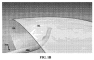
図1A乃至図8Gは、組織950の対向する層951及び952の間の間隙又は距離を閉じ又は狭幅化するために該組織950の2つの対向層951及び952間で操作可能な植設デバイス又はカテーテル3000を示している。図1Aを参照すると、植設デバイス3000は、組織950の第1層951と、該組織950の第2の対向する層952との間で操作される。上記組織は、例えば胃の組織であり得る。図1Bに示された如く、カテーテル又は植設デバイス3000のハウジング3001の遠位端は、組織950の第1層951に接近し又は接触されて該第1層に向けて導向されるべく操作される。ハウジング3001は、例えば案内ワイヤなどの任意の適切な機構により操作され得る。
FIGS. 1A-8G are implantation devices operable between two opposing
ハウジング3001の位置決め又は配向の後、インプラント担持用に鋭く尖端形状化されたニードル又はスリーブ3100がハウジング3001から遠位方向に延出され、例えば図2A及び図2Bに示された如く組織950の第1層951を穿刺して貫通する。ニードル3100は、例えば、ニチノール又はスプリング負荷鋼などの形状記憶材料で形成され得る。
After positioning or orientation of the
図2A及び図2Bに示された如くニードル3100が組織950の第1層951に穿刺されて所定距離だけ延出された後、ニードル3100の遠位部分は、例えば図3Aに示された如く、隣接する4本の延長部又は葉状部3105が、それらの間の長手方向スリットにより分離されることで、外方に拡開又は開花する。4本の延長部又は葉状部3105が配備されるが、任意の適切な本数が配備され得ることを理解すべきである。さらに、ニードル3100の遠位端は、類似する拡開を提供する1つ以上の弾性部分を有し得る。上述されたニードル2100は、ニードル3100の構造と類似する構造を有することで該スリーブ2100の縮動を許容し得ることを銘記されたい。
After the
各葉状部3105が外方に開き又は拡開するとき、ニードル3100の内部からはボタン状のインプラント又はプレート3200が露出される。図3A乃至図3Cに順次的に示される如く、例えばニチノール又はスプリング負荷鋼などの形状記憶合金から形成されたプレート3200は、未拡開のニードル3100の内側における格納を許容する折畳み形態から、展開又は拡開位置まで弾性移動する。
When each lobe 3105 opens or expands outward, a button-like implant or
プレート3200は平坦化された円筒形状を有するが、プレート3200は、例えば特定の用途に依存する任意の適切な形状及び/又はサイズを有すべく設計され得ることを理解すべきである。
It should be understood that although the
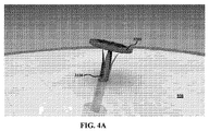
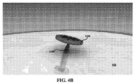
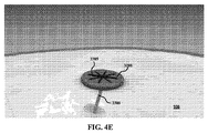
図4A乃至図4Eに順次的に示される如く、プレート3200が解放されて拡開された後、ニードル3100はハウジング3001内へと近位方向に後退する。ニードル3100が後退するにつれ、例えば編組された縫合糸などのコード3300であって、プレート3200に対して取付けられ且つニードル3100内へと貫通延在するコード3300が、プレート3200とニードル3100との間に露出される。さらに、ニードル3100が後退するにつれ、コード3300は、例えば図4Cに示された如くプレート3200が組織950の第1層951の外側又は遠位端表面に接触する程度まで、遠位方向に引っ張られる。
As shown sequentially in FIGS. 4A-4E, after the
コード3300は、プレート3200の種々の開孔をボタン状の様式で貫通延在する例えば吸収性又は非吸収性の縫合糸材料などの複数本の細線3305であって、該コードをプレート3200に対して固着する細線3305で形成される。但し、コード3300は、単一の撚線とされ得、且つ/又は、他の任意で適切な機構によりプレート3200に対して取付けられ得ることを理解すべきである。
The
図5A及び図5Bは、コード3300の対応長さがハウジング3001から遠位方向に解放されるのを許容し乍ら、近位位置までの上記カテーテルの再操作を順次的に示す図である。
5A and 5B are diagrams sequentially illustrating re-operation of the catheter to the proximal position while allowing the corresponding length of
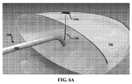
図6Aは、上記近位位置から上記器官の組織950の第2壁部又は層952までの上記カテーテルの操作を示しており、第2層952は、組織950の第1層951と対置されて該第1層から離間されている。図6Bは、第1層951を穿刺したのと同一のニードル3100であるか、又は、第1のニードル3100とは異なる第2のニードル3100であり得る、ニードル3100による第2層952の穿刺を示している。図6Bはさらに、上述された第1のプレート3200の展開と類似した様式で、組織950の第2層952の遠位端表面上での第2のボタン状インプラント又はプレート3200の展開を示している。
FIG. 6A shows the operation of the catheter from the proximal position to the second wall or
図6Cに示された如く、ニードル3100は次にハウジング3001内へと近位方向に後退され、該ハウジングは次に、上述された様式と類似する様式で図7Aに示された如く近位位置に戻り、第2プレート3200に対しては第2のコード3300が取付けられている。
As shown in FIG. 6C, the
図7A乃至図7Cは、2本のコード3300をハウジング3001内へと近位方向に引き込むことで2つのプレート又はインプラント3200を引き合わせる段階、及び、2本のコード3300を結合する段階及び挟持する段階を順次的に示している。2本のコード3300をハウジング3001内に引き込むことにより、各々がコード3300の対応する方に取付けられた2つのプレート3200は、相互に引き寄せられる。2つのプレート3200の近位端面と、組織900の対置された2つの層951及び952のそれぞれの遠位端面との間の接触の結果として、組織950の層951及び952は、例えば図7Cに示された如く相互に引き寄せられる。2本のコード3300を結合して挟持した後、植設デバイス3000は、図7D及び図7Eに順次的に示された如く、例えば器官などの手術部位から後退される。故に、上記の手順は、各コード3300により結合された対向する2つのボタン状プレート3200であって、組織950の対向する2つの層951及び952を例えば図7Dに示された如く相互に引き寄せられた位置に保持する2つのプレート3200の植設に帰着する。
FIGS. 7A-7C draw two
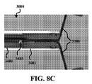
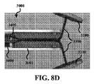
図8A乃至図8Gは、断面で示された植設デバイス3000により2本のコード3300を引っ張る段階及び挟持する段階を順次的に示している。図8Aを参照すると、ハウジング3001は図7Aに対応する近位位置に在る。各コード3300は、ハウジング3001の遠位端開口内へと、該ハウジング3001の内側ボアにおける丈に沿い延在する。各コードはまた、同様にハウジング3001の内側ボア内に配設された管状スリーブ3400の遠位端開口内へと延在する。管状スリーブ3400の遠位端には、一対のフック状の撚り合わせアーム3405が在る。図8B乃至図8Eに順次的に示された如く、各コード3300及び各撚り合わせアーム3405はハウジング3001に関して近位方向に後退される一方、管状スリーブ3400はその長手軸線の回りで回転する。管状スリーブ3400の長手軸線の回りにおける該スリーブの回転によれば、各撚り合わせアーム3405はそれぞれのコード3300に係合し、管状スリーブ3400の長手軸線の回りで回転する。各撚り合わせアーム3405の連続的な回転によれば、各コード3300及びスリーブ3400が近位方向に後退するにつれ、図8Eに示された如く各コード3300がそれらの所望の終端位置に到達し且つそれぞれのプレート3200がそれらの所望の接近状態に到達するまで、係合された各コード3400は連続的に且つ漸進的に撚り合わされる。各コード3300の後退の程度は調節されることで、組織950の2つの層951及び952間の閉塞の変化程度を達成し得ることを銘記されたい。各撚り合わせアーム3405のフック形状は、各コードをスリーブ3400の長手軸線から所定距離に保持する。これにより、各コード3300の撚り合わせの更なる制御が許容される。
FIGS. 8A to 8G sequentially show the steps of pulling and pinching the two
管状スリーブ3400はその長手軸線の回りにてハウジング3001及び組織950に関して回転するが、ハウジング3001及びスリーブ3400の両方が組織950に関して回転しても良いことを理解すべきである。例えば、スリーブ3400はハウジング3001に関して回転不能又は実質的に回転不能とされ得、スリーブ3400及びハウジング3001が一体的に回転して各コード3300を撚り合わせるときに、スリーブ3400はハウジング3001及び組織950に関して近位方向に後退する。
Although tubular sleeve 3400 rotates about its longitudinal axis with respect to
図8Eの所望位置が実現されたとき、それぞれのコード3300は一体的に結着されて一対のクリップ部材3500により切り詰められる。各クリップ部材3500は、例えば図8Eに示された初期位置から、図8Fに示された如く各コード3300の撚り合わせの遠位部分との接触へともたらされる。各コード3300を結合して切り詰めるために、各クリップ部材3500は、該各クリップ部材が一体的に噛み合わされて、各コード3300の近位端過剰部分3310から該コード3300の遠位端インプラント部分3305を分離するまで、さらに閉じられる。この段階にて、噛み合わされた各クリップ部材3500は植設デバイス3000の遠位端から解放されることにより、植設された部分3200、3305及び3500を植設デバイス3000から解放し、手術部位からの植設デバイス3000の後退及び取出しが許容される。故に、上記植設された各部分はそれらの植設位置に残置され、組織950の第1及び第2層951及び952を、相互に対する所望の接近状態に維持する。
When the desired position of FIG. 8E is realized, the
各クリップ部材3500は同時に、各コード3300の植設部分3305を結合し、且つ、(例えば、それぞれのクリップ部材3500上の近位端箇所において対向する各切断部材であって、インプラント部分3305が一体的に結着されるにつれ、相互に係合することで過剰部分3310を分離する各切断部材により)各コード3300から過剰部分3310を切断するが、各過剰部分3310は、異なる時点にて、且つ/又は、クリップ部材3500とは別体的な機構により、切り詰められ得ることを理解すべきである。
Each clip member 3500 simultaneously couples an implanted portion 3305 of each
さらに、各インプラント部分3305は、対向する2つのクリップ部材3500を締着して噛み合わせることにより結合されるが、他の結合機構が提供され得ることを理解すべきである。例えば、コード3300がポリマ材料で作成されるときなどには、各インプラント部分3305は例えば熱、圧力及び/又は高周波の印加により、相互に溶接又は溶着され得る。
Furthermore, although each implant portion 3305 is coupled by clamping and mating two opposing clip members 3500, it should be understood that other coupling mechanisms may be provided. For example, when the
プレート3200の使用は、当該構造が層951又は952の遠位端側又は反対側にキャビティを有する用途に対して特に適切であり得る。但し、他の用途においては、各プレート3200の内の1つ以上、例えば全てを、例えば以下に記述される留め具250、350、550などの係留用留め具の内の1つと置き換えることが好適であり得る。この点に関し、以下において相当に詳細に示される如く、留め具250、350、550の遠位端にて該留め具に対しては(例えば編組材料などの)縫合糸3300が取付けられると共に、該縫合糸は、上述の様式にて、例えばハウジング3001などのハウジングの遠位端内へと延在する。残りの操作は、プレート3200に関して上述されたのと同様であり、縫合糸3300が後退され、結合され、且つ、切り詰められる。但し、各組織部分の1つ以上(例えば全て)は、ボタン状プレート3200ではなく、(例えば留め具250又は300などの)係留用留め具の係合により引っ張られる。上記留め具は、該留め具を組織内へと直接的に発射し、又は、ニードル2100などの如きニードルを介して挿入するなどの、本明細書中に開示された任意の様式で載置され得る。2本以上のコード3300が後退され、撚り合わされ、且つ、結合され乍ら、2つより多いインプラント(例えば、プレート3200、及び/又は、留め具250、350などの留め具)が配備され得ることを理解すべきである。
The use of
コード/縫合糸3300、プレート3200、及び/又は、クリップ部材3500は、全体的に又は部分的に、例えばポリグリコール酸(PGA)又はPGA共重合体などの生体吸収性材料で形成され得る。
The cord /
図9は、一対の穿刺用のガーゼ(pledget)又はインプラント4200を示している。各穿刺用インプラントは、手術用デバイス3000に関して上述された特徴の全てを有する手術システムにおいて提供され得、穿刺用インプラント又はディスク4200がインプラント3200の代わりに配備される。両方のインプラント3200が各インプラント4200により置き換えられているが、上述されたインプラント3200と組み合わせて、1つの穿刺用インプラント4200が使用され得ることを理解すべきである。
FIG. 9 shows a pair of puncture gauze or
図9に示された如く、各インプラント4200は、インプラント3200に関して上述されたのと同一様式で展開かつ固着されている。インプラント4200は、インプラント3200と同様に、自己拡開式であり、且つ、ニードル3100から展開され得ることを銘記されたい。簡潔さのために、図9において各コード3300及びクリップ要素3500は示されない。
As shown in FIG. 9, each
インプラント4200は、該インプラントが各々、組織のそれぞれの層951及び952に接触する表面から延在する複数の組織穿刺歯部4205を備える、という点においてインプラント3200とは異なる。これらの鋭利尖端とされた突出部は、例えば、単位面積当たりの所定密度に従い、各インプラント4200の組織接触面の全体に亙り散在される。各歯部4205は、組織のそれぞれの層951、952を完全に貫通すべく選択された長さを有する。すなわち、歯部4205は、その鋭利尖端が、例えば、組織951及び952が同一器官の対向壁部同士であるときに該器官の内側表面などの、組織の対向面を貫通し且つそれを越えて延在することを許容する長さを有する。この完全な貫通は、組織からコラーゲンを自然に生成させる創傷であって、該コラーゲンを、各歯部4205により形成された孔を介し、対向する2つの組織951及び952間の空間内へと流入させる創傷を形成する。このことは有用である、と言うのも、それにより、対向する2つの組織951及び952の一体的な癒合が容易化されるからである。
The
図10A及び図10Bは、上述された手術システムに関連して使用され得る手術用マイクロ・インプラント又は留め具250を示している。但し、ディスク状インプラント3200及び/又は4200の内の1つ以上のインプラントが、インプラント250により置き換えられる。図10Bは図10Aの手術用インプラント250の断面図であり、断面平面は図10Aの留め具250の長手軸線に沿い延在して該長手軸線を含んでいる。留め具250は、留め具本体255の近位部285から近位方向に延在する縫合糸3300を有している。この点に関し、例えば塩水又は他の正確な水圧力の付与、又は、他の任意で適切な機構により、駆動器が留め具250を発射するとき、該留め具250が打ち込まれる深度は、縫合糸3300における弛緩の量により制限される。このことは、例えば、駆動器デバイス内の固定位置などの構造に対し、該固定位置と留め具本体255との間を所定の長さ及び/又は弛緩量とし乍ら、縫合糸3300の近位部及び/又は他の近位部分を固定することにより達成され得る。
10A and 10B show a surgical microimplant or
図10Bの断面図を参照すると、縫合糸3300は、留め具本体255の内部箇所290内へと長手方向に延在し得る。代表的な製造方法としては、縫合糸3300上への留め具ヘッド905の型成形、共押出し成形、又は、別様の形成が挙げられる。但し、任意の適切な製造方法が採用され得ることを理解すべきである。さらに、延伸不能な材料の縫合糸3300が提供されるが、例えば延伸可能な材料などの他の材料が提供され得ることを理解すべきである。但し、延伸可能な材料であっても、その材料は、特定の駆動運動量及び/又は用途に対して所定の延伸限界を有することが好適であり得る。さらに、編組された、非編組の、単繊維の、及び/又は、多繊維の材料が提供され得る。
Referring to the cross-sectional view of FIG. 10B, the
留め具250は、組織内へと係留されると共に植設後には近位方向への転位に抗するためにマイクロ繊維275を含むが、例えば、上述された翼部などの他の任意の係留機構が配備され得ることを理解すべきである。さらに、留め具250に関しては、本明細書中に開示された他の代表的なインプラントに関して開示された特徴の内の任意の特徴が配備され得る。
The
図11は、上述のニードル3100と共通する多くの特徴を含むニードル5600を示している。但し、ニードル5600は、留め具250を組織951、952内の所定箇所に位置決めすべく構成される。
FIG. 11 shows a needle 5600 that includes many features in common with the
さらに、ニードル5600は、その内部に収容される留め具よりも小さな静止又は初期直径を有することが好適であり得る。例えば図11に示された如くニードル5600は、留め具250と同一である留め具650が該ニードル5600内に挿入されたとき、各金属バンド5605は外方に膨出し、隣接する各金属バンド5605間に拡開間隙を形成する。このことは、ニードル5600が後退されるときに、繊維及び/又は他の単一又は複数の係留機構が近傍の組織に係合して各留め具の近位方向移動に抗することを許容するために有用であり得る。例えば、図11に示された如く、留め具650の係留用マイクロ繊維675は、ニードル5600の隣接バンド5605同士の間で長手方向に延在する間隙を通して露出されることから、各繊維675は、ニードル5600の後退の初期段階においてさえも、周囲組織に係合することが許容される。この点に関し、組織に対する各繊維675の係合は、それら自体においてそれら自体が十分であることで、留め具650をその植設位置に残置し乍ら、ニードル5600の近位方向への後退を許容し得る。但し、ニードル5600に関連して、例えば押圧ロッドなどの他の機構が配備されることで、インプラント650をその所定箇所に保持し乍ら、ニードル5600の後退を促進し得ることを理解すべきである。一定の用途は上記インプラントの完全な貫通を必要としないことから、ニードル5600は、組織951、952の外側面を阻害又は穿刺しない深度まで貫通することのみを必要とし得る。
Furthermore, it may be preferred that the needle 5600 has a smaller stationary or initial diameter than the fasteners housed therein. For example, as shown in FIG. 11, the needle 5600 is identical to the
インプラント250の特徴に関する以下の考察を含め、本明細書における考察は、特徴の任意の差違が明示的に言及される処を除き、本明細書中に開示された他のインプラント350、550、650にも適用される。
The discussion herein, including the following discussion of the features of the
吸収性又は非吸収性とされ得る手術用インプラント250は、内臓又は組織の平面を貫通すべく設計される。各インプラント250は、所定深度まで、制御下での高速の展開のもとで組織内へと貫通すべく設計される。上記インプラントは、所定の幾何学形状を備えるニードルと同様に形状化される。各インプラント250は、遠位端領域において先細状とされてニードル状尖端260に至る長寸本体255を有している。各インプラント250は、例えば、該インプラント250を収容すべく正確に載置された中空のニードル又は管体から押し出されることにより、展開され得る。インプラント250、並びに、本明細書中に開示された他の任意の代表的なインプラントは、例えば、マイクロ加工技術を用いて形成され得る。
The
マイクロ・インプラント250は、1ミリメートル、又は、約1ミリメートルの直径と、5ミリメートル〜10ミリメートルの範囲である長さとを有し得る。代表的実施例に依れば、上記直径は、1ミリメートル未満である。代表的実施例に依れば、上記直径は0.8ミリメートル〜1.2ミリメートルの範囲である。但し、他の寸法が提供され得ることを理解すべきである。 The micro-implant 250 may have a diameter of 1 millimeter or about 1 millimeter and a length that ranges from 5 millimeters to 10 millimeters. According to an exemplary embodiment, the diameter is less than 1 millimeter. According to an exemplary embodiment, the diameter ranges from 0.8 millimeters to 1.2 millimeters. However, it should be understood that other dimensions may be provided.
各インプラント250の本体255は、該インプラント250の芯部から立ち上がり、其処から外方に延在すべく特に設計されたマイクロ係留繊維275を有する。各係留用繊維275は、インプラント250の本体255の円周部の回りにて、該本体の丈の少なくとも一部分に沿い配置される。これによりインプラント250は、それが組織を一旦貫通したなら、離脱に抗することが許容される。
The
各繊維275は、任意の適切な寸法を有し得る。例えば、それは、0.1ミリメートルの繊維尖端(すなわち自由端部)直径を実現し、上記本体における0.25ミリメートルの直径に向けてテーパ付けされることが有用であり得る。
Each
例えば円筒状である上記芯部は、インプラント250の本体255の相当の長さに沿い、一定の直径を有する。例えば、インプラント250の芯部は、近位部から、尖端260に向かう実質的に円錐状に形状化されたテーパ付き部分へと、一定の断面積及び一定の直径を有する。但し、インプラント250は、さらに連続的なテーパを有し得、且つ/又は、一定の又は不定の割合のテーパを有し得ることを理解すべきである。
The core, for example cylindrical, has a constant diameter along a substantial length of the
各係留用繊維275は、インプラント250の長手軸線に関して所定角度にて外方に延在する。この点に関し、各繊維は、上記長手軸線から離間して外方に延在することに加え、尖端260から離間して近位方向にも延在する。これにより、各繊維275は、遠位方向への駆動又は挿入の間において、穿刺された組織に沿い摺動することが許容される。但し、挿入された位置からのインプラント250の近位方向移動は、比較的に軟質の組織に対する各繊維275の外側の自由端部の係合により、阻止され又は抵抗される。各繊維275は、撓曲可能であるか、又は、実質的に堅固であり得る。但し、繊維275は、挿入された位置からのインプラント250の近位方向への引き戻しに抗するに十分な剛性又は強度を有さねばならない。さらに、各繊維275は直線状であると示されるが、繊維275の幾本又は全ては、少なくとも部分的に湾曲され、且つ/又は、直線状部分及び/又は湾曲部分間に1つ以上の屈曲部を有し得ることを理解すべきである。さらに、所定のインプラント250の各繊維275は、該インプラント250の長手軸線に関し、一定の又は異なる丈、径方向広がり、及び/又は、角度を有し得る。
Each anchoring
各マイクロ繊維275は、特定用途に依存し、任意の適切な密度及び相対間隔を備え得る。所定の用途に対しては、同一の又は同等の縫合糸保持強度又は“貫通強度”を呈し乍ら、さらに高い密度(すなわち、単位面積当たりでさらに多数の繊維)のさらに小さな繊維が配備されるか、又は、(選択的に、例えばニチノール及び/又はスプリング負荷鋼などの形状記憶合金で強化された)さらに低い密度のさらに大きな繊維が配備され得る。上記の選択的な強化は、例えばニチノール及び/又はスプリング負荷鋼などの形状記憶合金で形成された“V“形状部分であり得る。各繊維275は、全体的に又は部分的に、吸収性又は非吸収性であり得る。
Each
留め具250は、該留め具250を組織内に係留すべくマイクロ繊維275を使用するが、任意の適切な係留機構が配備され得ることを理解すべきである。例えば、スプリング負荷されたタブが配備され得る。
各インプラント250は近位端表面285を有し、該表面を介し、例えば塩水水圧、スプリング力、又は、他の任意で適切な機構により、駆動力が付与され得る。インプラント250の近位端表面285は、縫合糸3300が近位方向に延在する表面であって、芯部220と直径が同一又は実質的に同一である表面に対応する。但し、表面285に対しては任意の適切な配置箇所又は寸法が提供され得る。
Each
インプラント250は円形の断面を備えた芯部を有するが、例えば、矩形状、三角形状、楕円形状、多角形状、及び/又は、他の任意の規則的な又は不規則的な形状などの、他の断面が配備され得ることを理解すべきである。さらに、各係留用マイクロ繊維275は、均一に離間され得るか、又は、不均一な間隔を有し得ることを理解すべきである。さらに、繊維の密度、すなわち、上記芯部の単位面積当たりの繊維275、575、675の本数は、一定とされ得るか、変化し得る。
図12は、該図12に示された遠位部分を除いてインプラント250と同一であるインプラント550の遠位部分を示している。その遠位端配置構成は、鋭利尖端560を形成すべく遠位方向に収束する3つの凹状表面580を含む。3つの凹状表面580を分離しているのは、3つのテーパ付き切断用縁部585である。これらのテーパ付き切断用縁部585は、例えば軟組織などの組織の貫通を促進し得る。図12に示された端部は、3つの対応するテーパ付き切断用縁部585により分離された3つの凹状表面580を含むが、任意の適切な個数の凹状表面580及び対応する切断用縁部585が配備され得ることを理解すべきである。
FIG. 12 shows a distal portion of an
さらに、図13は、留め具250と共通する特徴を有すると共に、本明細書中に記述された結着用途の内の任意の用途と関連して使用され得る手術用マイクロ・インプラント又は留め具350を示している。但し、留め具350は波形本体351を含んでいる。本体351は、該本体351の丈に沿い軸線方向に延在する溝353を含んでいる。故に、本体351の円周回りに延在する複数の溝353は、複数の隆起部355と交互配置される。さらに、留め具本体351は、一対の分割部分又は翼部357及び358を含む。上記各分割部分は、本体351内へのそれぞれの裂け目又は切り込み359により形成される。この点に関し、裂け目359は、本体351内に径方向に切り込みを作成して軸線方向に延長することにより形成され得る。故に、2つの分割部分357及び358は、遠位位置にて本体351の残部に対して取付けられると共に、自由端部まで近位方向に延在する。各自由端部は、湾曲表面に沿う複数の鋭利な突出部を含む。これらの尖端は、上記波形部により形成される。特に、隆起部355は鋭利な突出部を形成する。特に、隆起部355は図13における差込み部分的側面図に示された如く上記鋭利な突出部を形成し、これらは、組織を把持して留め具250の遠位端摺動を阻止するために有用である。図示された如く各分割部分357及び358は斯かる3つの突出部を含むが、留め具350は、各分割部分の内の1つ以上が、単一の鋭利な突出部などの、他の任意の個数の突出部を有する如く設計され得ることを理解すべきである。例えば、さらに多数の鋭利な突出部が所望されるなら、本体351はさらに稠密に波形状とされ(例えば、さらに多数の交互配置された溝353及び隆起部355が配備され得)、且つ/又は、上記切り込み又は裂け目の角度が調節され得る。さらに、各突出部の近位方向の広がりの長さは、隆起部355に関する溝353の深度を変化させることにより調節され得る。
Further, FIG. 13 shows surgical microimplants or
分割部分357及び358は、組織内への遠位方向の挿入はそれほど阻害しないが、組織に係合することで、挿入箇所からの近位方向の移動には抵抗する。分割部分357及び358の尖端形状化され且つ/又は鋭利縁部化された近位端と、該分割部分の近位端上で交互配置された隆起部との組み合わせによれば、優れた性能が実現されることが見出されている。
さらに、分割部分又は翼部357及び358は、軸線方向において相互からオフセットされる。例えば、分割部357は軸線方向において軸線xに沿う箇所aに配置され、且つ、分割部358は軸線方向において軸線xに沿う箇所bに配置される。これにより、非オフセット構成と比較して、本体351の他の部分のさらに大きな構造的強度が許容される。特に、各切り込みは、それらが遠位方向に進展するにつれて連続的に径方向内側に進展することから、当該部分がオフセットされなければ、切り込みの遠位端における断面の材料は相当に少量となる。このことは、上記本体の軸線に沿う機械的に脆弱な箇所又は領域に繋がり、且つ、特に小寸法の留め具において、機械的な破損に繋がり得る。
Further, the split portions or
留め具350の遠位端は、鋭利尖端と、該鋭利尖端に収束する複数の縁部により分離された複数の表面とを備えた、角錐状である。4つの平坦な表面が配備されるが、任意の適切な個数の表面が配備され得ること、及び、各表面の1つ以上又は全てが非平坦であり得ることを理解すべきである。
The distal end of
留め具350はまた、フック状端部360も含む。該フック状部分は、他の任意の一時的な及び/又は永続的なインプラントに連結されるに適切であり得る。例えば上記フックは、縫合糸3300を固着すべく使用され得る。但し、留め具350は好適には、留め具250に関して記述された如く、例えば縫合糸3300と共に型成形又は共押出し成形されることにより、該留め具と共に延在する縫合糸3300が形成され得る。さらに、上記フック状端部は、省略されても良い。
The
留め具350は、先ず、例えば射出成形又は押出し成形などにより波形を備えた本体351を形成し、引き続き、例えば本体351の側面を径方向に切り込むことで翼部357及び358を形成することにより作製され得る。図示された如く上記切り込みは、本体351の長手軸線に対し、最初の近位端切り込み箇所から、留め具350の遠位端に向けて次第に減少して最終的には直線状になる角度(近位端の進入点)を以て湾曲される。図示例の上記分割部又は切り込みは本体351の長手軸線に関して湾曲され又は変化角度を以て作成されるが、直線状の切り込みなどの任意の適切な切り込みが作成され得ることを理解すべきである。
The
留め具350は本体351の径方向周縁部の回りで等しく離間された2つの翼部を含むが、単一の翼部などの任意数の翼部が、径方向周縁部の回りで任意の適切な間隔で配備され得ることを理解すべきである。
The
さらに、波形状とされて分割された本体の構成は、本明細書中に開示された他の留め具の任意の特徴と組み合わせて採用され得ることを理解すべきである。例えば、留め具350は、上記分割部分に加えて、複数の繊維を含み得る。
In addition, it should be understood that the corrugated and split body configuration may be employed in combination with any of the other fastener features disclosed herein. For example, the
図14を参照すると、手術システム5000は、例えば所定深度まで留め具250を駆動するハンドピース5100を含んでいる。上記深度は、例えば縫合糸3300における所定量の弛緩により制限される。縫合糸3300の近位部は、当該巻上げ器5105から延在する該縫合糸3300の長さを調節すべく構成された巻上げ器5105に対して取付けられる。この点に関し、モータシステム又は他の任意で適切な機構により起動され得る巻上げ器5105は、留め具250の駆動に先立ち所定長さの縫合糸3300を巻き出すことにより上記弛緩量を設定し得、且つ/又は、巻上げ器5105は、留め具250を駆動すると該巻上げ器は所定量だけ回転することで留め具250の駆動深度を設定する如く、所定量の許容回転を行い得る。留め具250の深度及び/又は駆動速度の決定は、ハンドピース5100のプロセッサ5110において決定され得る。上述のデバイス3000は、同様のハンドピースを含み得る。上記処理はハンドピース5100内に配置されたプロセッサ5110において行われるが、上記プロセッサは、例えばシャフト5115内などの、上記デバイスの他の部分内に配設され得ること、及び/又は、上記処理は、例えば、無線にて上記手術用デバイスと通信する遠隔演算ユニットにおけるなどの、ハンドピース5100から離間した箇所で行われ得ることを理解すべきである。さらに、巻上げ器5110は、シャフト5115内に配設され得ることを理解すべきである。
Referring to FIG. 14, the
シャフト5115は、上述のカテーテル3000の、例えば操作性、巻き取り機構、及び、挟持機構などの多くの特徴を含み得る。
The
処置の間、システム5000は上述のデバイス3000と同様の様式で動作する。但し、各インプラント3200の内の1つ以上は、インプラント250により置き換えられる。各インプラント250は、水圧的に投入され得るか、又は、穿刺用ニードル、又は、他の任意で適切な駆動機構により投入され得る。水圧的な投入に関し、留め具250を駆動するシャフト5115の遠位部分にては、非常に正確な力が付与されることを銘記されたい。この力は、例えば上記ハンドピースにおける水圧機構に関してプロセッサ5110により制御され得る。例えば、シャフト5115に沿い延在する管体内には、例えば塩水などの水圧流体が配設され得る。次に、ハンドピース5100内の水圧機構及び制御機構は、シャフト5115に沿い延在する水圧流体を介し、非常に正確な力を該シャフト5115の遠位部分に伝達し、留め具250を正確に駆動し得る。
During the procedure, the
図14に示された如く、留め具250は組織951、952へと打ち込まれる。例えば、組織の対置層に再位置決めされるべく上記シャフトが植設箇所から後退されるとき、巻上げ器5105は対応する長さの縫合糸3300を巻き出す。さらに、例えば更なる留め具250などの第2のインプラントを駆動した後、2本の縫合糸3300は、デバイス3000に関して上述された様式で巻き取られる。巻き取りの間、上記巻上げ器は、例えばプロセッサ5110からの制御信号に従い起動されることで、縫合糸3300を漸進的に巻き取り得る。但し上記巻上げ器は、例えば、以下に記述される管体5400の如き後退式の巻き取り用管体に関して移動すべく取付けられる場合には、一切の回転に抗すべく制御され得る。各縫合糸3300はそれら自体のそれぞれの巻上げ器5105を有し得るか、又は、各縫合糸3300は1つの巻上げ器機構を共有し得る。もし各縫合糸3300が1つの巻上げ器機構を共有するなら、該機構は、例えば、留め具の駆動手順の間において、各縫合糸3300を独立的に後退/延出させる機構を備えるべく構成されることが有用であり得る。さらに、単一又は複数の巻上げ器5105は、例えばフックなどの撚り合わせ境界部の近位端側における一切の不都合な撚り合わせを回避すべく、縫合糸撚り合わせ機構に対して連結され得る。
As shown in FIG. 14,
図15Aは、図14のデバイスを用いて係留用留め具250を第1組織1951を貫通して第2組織1952へと打ち込む段階を示している。
FIG. 15A shows the step of driving the anchoring
図15Bは図15Aの第1及び第2の組織1951、1952を示しており、係留用留め具250は第1組織内に植設され、且つ、該係留用留め具250に取付けられた縫合糸3300は第1組織1951を貫通延在している。
FIG. 15B shows the first and
図15Cは図15Bの第1及び第2の組織1951、1952を示しており、第2の係留用留め具250は第2組織1952を貫通して第1組織1951内へと打ち込まれ、且つ、図14Aのデバイスは各係留用留め具250に取付けられたそれぞれの縫合糸3300を撚り合わせている。
FIG. 15C shows the first and
図15D乃至図15Fは、図15Cの各係留用留め具に取付けられたそれぞれの縫合糸の引き戻し、撚り合わせ及び締着により2つの組織を結合する段階を順次的に示している。 15D-15F sequentially show the steps of joining the two tissues by pulling back, twisting and fastening the respective sutures attached to each anchoring fastener of FIG. 15C.
図15Gは、図15A乃至図15Fの手順とは異なる角度及び箇所にて各組織内へと打ち込まれた留め具を示している。 FIG. 15G shows a fastener driven into each tissue at an angle and location different from the procedure of FIGS. 15A-15F.
図15D乃至図15Fは、各留め具250を採用する接近化手順を順次的に示している。図15Cに示された如く、各留め具250は対置された組織1951及び1952に打ち込まれており、且つ、各縫合糸3300は、デバイス3000に関して上述されたのと類似する様式で引き戻されて撚り合わされているところである。管体部分5115内には、各縫合糸3300を巻き取り且つ引き戻す当該巻き取り用管体5400の各巻き取りフック5405と共に回転し且つ後退する巻き取り用管体5400が在る。管体5115の遠位部分には、一対の起動可能なクリップ要素5500が配設される。これらの要素5400、5405及び5500は、デバイス3000に関して上述された要素3400、3405及び3500と同様の特徴を有している。
15D to 15F sequentially show the approaching procedure that employs each
図15Dに示された如く、各縫合糸3300は、各縫合糸の近位部分の撚り合わせ及び引き戻しの故に相互に向けて組織1951、1952が移動しているときに、緊張状態に在る。
As shown in FIG. 15D, each
図15Eに示された如く、組織1951、1952は、相互に接触されており、且つ、各縫合糸3300により確実に保持されている。
As shown in FIG. 15E, the
図15Fに示された如く、各クリップ要素5500は、クリップ部材3500に関して上述されたのと同一様式で各縫合糸3300を挟持して結合すべく起動されている。この配置構成は、各インプラント250が植設されるそれぞれの組織1951及び1952の全厚の貫通を必要としないことを銘記されたい。すなわち、各係留用留め具の鋭利尖端は、組織の外壁を越えて露出されるべく穿刺される必要はない。このことは、上記組織に対する損傷を減少し、且つ、一切の隣接組織を損傷する可能性を制限するために有用であり得る。但し、各留め具250は、それぞれの留め具が植設される対応組織1951及び1952の外壁を越えて尖端が延在する如き深度まで打ち込まれ得ることを理解すべきである。
As shown in FIG. 15F, each
図15Fの配置構成は、図示された2つの組織1951、1952の端部同士を相互に固着する閉塞部を維持する。
The arrangement of FIG. 15F maintains a blockage that secures the ends of the two illustrated
図15Gは、図15A乃至図15Fの配置構成と類似するが、当該各軸線に沿い各留め具250が打ち込まれる軸線同士の間における角度が小さい、という点で異なる配置構成を示している。さらに、各留め具250は、組織1951、1952のそれぞれの端面を通して打ち込まれている。この点に関し、各留め具250は、相互に対して(例えば実質的に180°を含め)任意の適切な角度にて、且つ、それぞれの組織1951、1952に関して任意の適切な角度又は箇所にて打ち込まれ得ることを理解すべきである。
FIG. 15G is similar to the arrangement of FIGS. 15A to 15F, but shows a different arrangement in that the angle between the axes along which each
本明細書中に開示された一切の代表的なインプラントの駆動器は、本明細書中に記述された代表的な留め具の内の任意の留め具を、所定深度まで駆動すべく構成され得る。深度の精度は、例えば、塩水流体などによる正確な水圧式駆動力、フランジ又は他の同様の停止部に対する係合、又は、深度を制限すべく張設される縫合糸などの、任意の適切な機構により達成され得る。さらに、上記深度は、螢光透視法、又は、他の任意で適切な画像化機構を用いて監視され得る。上記駆動機構は、内視鏡カテーテル・シャフトを通し加圧される加圧塩水又は他の水圧流体を含み得る。故に、非常に正確な制御が達成され得る。 Any exemplary implant driver disclosed herein may be configured to drive any of the exemplary fasteners described herein to a predetermined depth. . Accuracy of depth, for example, accurate water pressure driving force due brine fluid engagement with flanges or other similar stop, or, such as sutures stretched to limit the depth, any suitable It can be achieved by a mechanism. In addition, the depth can be monitored using fluoroscopy or any other suitable imaging mechanism. The drive mechanism may include a pressurized圧塩water is pressurized through the endoscopic catheter shaft or other water fluid. Therefore, very accurate control can be achieved.
代表的実施例に依れば、例えばプロセッサ5110を含むコンピュータ・システムは、例えば2つの尖端の箇所を決定すると共に、それらの間の距離を決定し得る。上記距離は、当該留め具が発射されて至るべき所望距離として使用され得る。上記植設距離は、例えば、調節可能な停止部又はフランジ、上記留め具に対して取付けられたコード又は縫合糸などの任意の適切な調節機構により、且つ/又は、(例えば水圧推進システムを正確に制御することにより)植設の間に留め具の速度及び運動量を正確に制御することにより、設定され得る。斯かる深度の測定、決定及び/又は制御は、本明細書中に開示された留め具の任意の植設に関連して採用され得る。
According to an exemplary embodiment, a computer system that includes, for example,
上記各留め具は好適には、50メートル/秒より速い速度、さらに好適には50〜350メートル/秒の範囲内、最も好適には350メートル/秒にて駆動される。但し、各留め具は、該留め具が組織を穿刺するに十分である任意の適切な速度にて駆動され得ることを理解すべきである。 Each fastener is preferably driven at a speed greater than 50 meters / second, more preferably in the range of 50 to 350 meters / second, most preferably 350 meters / second. However, it should be understood that each fastener can be driven at any suitable speed that the fastener is sufficient to puncture tissue.
最近の製造プロセスによれば、略ナノの技術応用が許容される。これにより、インプラント250及び本明細書中に開示された他の任意のインプラントは、過去においては可能ではなかったかも知れないサイズ及び複雑さにて製造され得る。インプラント250は、吸収性又は非吸収性のポリマのいずれかで射出成形されてから、処理されることで突出繊維275の特定構造を付加し得る。
According to recent manufacturing processes, almost nano-technical applications are allowed. This allows the
インプラント250はポリマで形成されるが、例えば金属又は複合材料などの任意の適切な材料が使用され得ることを理解すべきである。
Although
遠位端側にて保持又は固着されていない隣接組織を正確に貫通すべく、所望の貫通を行うためには、組織の単一又は複数の層の高速な貫通が必要とされ得る。もしインプラント250が低速に付与されるなら、上記組織は、適切な貫通なしで、該インプラント及び/又はニードルにより遠位方向に離間して押圧され得る。故に、幾つかの代表的な投入機構は、上記インプラントを比較的に高速で発射する。幾つかの好適実施例においては、インプラント250を上記の正確な速度にてプランジャが発射する如き速度にて、カテーテル又はニードル内のチャネルを加圧すべく塩水が使用される。他の代表的実施例は、上記インプラントを発射するスプリング負荷式の機械的機構を利用する。更なる代表的実施例は、カテーテルの丈に沿い延在する長寸の押圧ロッドを用いてインプラントを押圧する。発射の手法は、コンピュータ制御式とされ得る。但し、発射は、例えば操作者制御式とされ得ることを理解すべきである。例えば、外科医などの操作者によりトリガされるスプリング負荷システムなどの機械的システムにより、発射力は事前決定され且つ反復可能とされ得る。
Fast penetration of single or multiple layers of tissue may be required to achieve the desired penetration to accurately penetrate adjacent tissue that is not held or secured at the distal end. If the
上述された機構及びデバイスの内の任意のものは、例えば、任意の適切な圧力検知機構を用いてニードル又は留め具を進展させるために必要とされる圧力を検知するなどの圧力検知と共に利用され得る。上記圧力は、例えば、本明細書中に記述された各実施例の内の任意の実施例の植設デバイスが連結されるハンドピース5100などのハンドピース内のプロセッサ5110などのコンピュータ制御システムへと伝達され得る。さらに、例えば超音波又は他のデジタル画像などの画像化データが獲得されると共に、該データは、例えば、ハンドピース内のコンピュータ制御システムへと伝達され得る。圧力及び/又は画像情報及び/又は他の任意の検知情報などの該情報は、上記制御システムにより使用されることで、組織内への種々のニードル及び/又はインプラントの挿入を適切に制御し得る。例えば、上記制御システムは、挿入の速度、箇所、角度、及び/又は、深度を制御し得る。斯かる正確な制御は、インプラントの非常に正確な載置を必要とする心臓内の欠陥を修復するときに特に有用であり得る。
Any of the mechanisms and devices described above may be utilized with pressure sensing, such as sensing the pressure required to advance the needle or fastener using any suitable pressure sensing mechanism. obtain. The pressure is applied, for example, to a computer control system such as a
本明細書中に記述された種々の機構は、相当の融通性を許容する組織修復システムを提供する。例えば、さらに小寸の欠陥は(例えば、留め具100、又は、本明細書中に記述された他の任意の留め具などの)単一留め具により修復可能とされ得ると共に、さらに大寸の欠陥は、上述された如くワッシャ又はプレート2200ありで又はなしで、複数の留め具により修復可能とされ得る。例えば、ヘルニア又は大寸の孔などのさらに大寸の欠陥は、上述された如く、メッシュ1300の適用にさらに適切であり得る。
The various mechanisms described herein provide a tissue repair system that allows considerable flexibility. For example, a smaller defect can be made repairable by a single fastener (eg,
例えば留め具250、350、550、650、プレート3200、などの本明細書中に記述された種々のインプラント、及び、クリップ要素3500、4500は、例えば射出成形などの型成形により形成され得る。
For example, the various implants described herein, such as
さらに、留め具250、350、550、650は、該留め具に関する組織の近位方向移動を抑制するヘッド要素を備え得る。さらに、上記ヘッド要素は固定され得るか、該ヘッド要素は、例えば、上記留め具が、対応するラチェット形成又は螺条形成されたヘッド要素を受容すべく構成されたラチェット形成又は螺条形成された近位部分を有する場合には、移動可能とされ得る。
Further,
さらに、例えば、留め具250、350、550、650、プレート3200、4200、及び、クリップ要素3500、5500、及び/又は、縫合糸3300などの本明細書中に記述された植設可能な要素の内の任意の要素は、例えば特定の用途に依存して、患者の体内へと吸収可能な材料、又は、非吸収性の材料で全体的又は部分的に形成され得る。例えば、これらの要素は、ポリグリコール酸(PGA)、又は、PGAポリマで形成され得る。これらの要素は、同様に、又は、代替的に、ポリエステル及び/又はナイロン及び/又は他のポリマの共重合体で形成されても良い。さらに、これらの要素は、例えば、ニチノール及び/又はスプリング負荷鋼などの一種類以上の形状記憶合金を含み得る。
Further, for example, the implantable elements described herein, such as
種々のインプラントの誤発射、又は、不適切な位置決めの可能性がある場合、吸収可能材料が有用であり得る。例えば、留め具又は他のインプラントが意図されない箇所に駆動される場合、又は、組織がインプラントを適切には受容しない場合、上記インプラントは、必要とされないとしても、比較的に無害である、と言うのも、それは最終的に患者の体内に吸収されるからである。 Absorbable materials may be useful when there is a possibility of misfire of various implants or improper positioning. For example, if a fastener or other implant is driven to an unintended location, or if tissue does not properly receive the implant, the implant is said to be relatively harmless, if not required. This is because it is eventually absorbed into the patient's body.
本発明は特定の例及び好適実施例に関して記述されたが、上述の記述は限定的でないことを理解すべきである。さらに、本明細書中に記述された特徴は任意の組合せで使用され得る。
なお、本発明の別の態様によれば、内側チャンバと組織を穿刺するように構成された鋭利尖端とを有する中空ニードルと、折り畳み位置及び拡開位置を有する第1自己拡開式アンカであって、前記折り畳み位置に在るときには前記内側チャンバ内に位置決め可能である第1自己拡開式アンカと、前記ニードルを貫通延在すると共に前記第1アンカに対して取付けられた第1縫合糸と、前記第1アンカを収容する前記ニードルを組織の第1部分における第1所定位置へと打ち込むように構成されたアクチュエータと、を具備する手術用デバイスであって、前記ニードルが前記第1所定位置から引き戻されて前記第1アンカを前記第1所定位置に残置し得ると共に前記第1アンカが前記ニードルの引き戻し時に前記折り畳み位置から前記拡開位置へと拡開し得る手術用デバイスが提供される。
折り畳み位置及び拡開位置を有する第2自己拡開式アンカであって、該第2自己拡開式アンカが前記折り畳み位置に在るときには前記内側チャンバ内に位置決め可能である第2自己拡開式アンカと、前記ニードルを貫通延在すると共に前記第1アンカに対して取付けられた第2縫合糸と、をさらに具備し、前記アクチュエータが、前記ニードルを前記第2アンカと共に前記組織の第2部分における第2所定位置へと打ち込むように構成され、前記ニードルが、前記第2所定位置から引き戻されて前記第2アンカを前記組織の第2部分を遠位方向に越えた位置に残置し得ると共に、前記第2アンカが、前記ニードルの引き戻し時に前記折り畳み位置から前記拡開位置へと拡開し得る。
前記第1縫合糸及び前記第2縫合糸の各々が編組縫合糸である。
当該手術用デバイスが、前記第1縫合糸及び前記第2縫合糸を当該手術用デバイスの遠位端内へと遠位方向に引き戻すことで前記第1アンカ及び前記第2アンカを引き合わせるように構成されたアクチュエータを有し、前記第1アンカ及び前記第2アンカを引き合わせると、前記組織の第1部分が前記組織の第2部分に向けて引っ張られる。
前記縫合糸の各々が遠位方向に引き戻されるときに、それらは撚り合わされる。
前記第1縫合糸を前記第2縫合糸に対して結合するように、且つ、該第2縫合糸に対する前記第1縫合糸の結合部の遠位端側における前記第1縫合糸及び前記第2縫合糸の過剰部分を切断するように構成された締着具をさらに具備する。
なお、本発明のさらに別の態様によれば、第1縫合糸に対して連結された第1インプラントと、第2縫合糸に対して連結された第2インプラントと、前記第1インプラントを第1組織に関して第1所定位置に位置決めするように、且つ、前記第2インプラントを第2組織に関して第2所定位置に位置決めするように構成されたインプラント駆動器であって、該インプラント駆動器は前記第1縫合糸及び前記第2縫合糸を相互に引き寄せて各インプラントを並置することで前記第1組織及び前記第2組織を並置するように構成される、インプラント駆動器と、を具備する手術システムであって、前記第1インプラント及び第2インプラントが、前記第1組織及び前記第2組織が並置されたときに、該第1組織及び第2組織の境界部において該第1組織及び前記第2組織の両方を穿刺すように構成された手術システムが提供される。
前記第1インプラントが第1ディスクであり且つ前記第2インプラントが第2ディスクである。
前記第1ディスクが前記第1組織を完全に貫通して切断するように各々が構成された複数の突出部を有し、且つ、前記第2ディスクが前記第2組織を完全に貫通して切断するように各々が構成された複数の突出部を有する。
なお、本発明のさらに別の態様によれば、第1インプラントを第1組織の近傍の第1所定位置に位置決めする段階と、第2インプラントを第2組織の近傍の第2所定位置に位置決めする段階と、前記第1インプラント及び第2インプラントを互いに対して並置状態へと引き合わせることにより前記第1組織及び前記第2組織を並置状態へともたらす段階と、前記第1インプラント及び前記第2インプラントにより前記第1組織及び前記第2組織の各々に複数の穿刺創傷を生成する段階と、を含む方法が提供される。
Although the invention has been described with reference to specific examples and preferred embodiments, it is to be understood that the above description is not limiting. Further, the features described herein can be used in any combination.
According to another aspect of the present invention, there is provided a hollow needle having an inner chamber and a sharp point configured to puncture tissue, and a first self-expanding anchor having a folded position and an expanded position. A first self-expanding anchor positionable in the inner chamber when in the folded position, and a first suture extending through the needle and attached to the first anchor. A surgical device comprising: an actuator configured to drive the needle containing the first anchor into a first predetermined position in a first portion of tissue, wherein the needle is in the first predetermined position. The first anchor can be left in the first predetermined position by being pulled back from the first position, and the first anchor is moved from the folded position to the expanded position when the needle is pulled back. Surgical device is provided that can be expanded with.
A second self-expanding anchor having a folded position and an expanded position, wherein the second self-expanding anchor is positionable within the inner chamber when the second self-expanding anchor is in the folded position. An anchor and a second suture extending through the needle and attached to the first anchor, the actuator including the second anchor and the second anchor of the tissue. And the needle can be pulled back from the second predetermined position to leave the second anchor in a position distally beyond the second portion of the tissue. The second anchor can expand from the folded position to the expanded position when the needle is retracted.
Each of the first suture and the second suture is a braided suture.
The surgical device pulls the first suture and the second suture back into the distal end of the surgical device in a distal direction to bring the first and second anchors together. Having a configured actuator, when the first anchor and the second anchor are pulled together, the first portion of the tissue is pulled toward the second portion of the tissue.
As each of the sutures is pulled back in the distal direction, they are twisted together.
The first suture and the second on the distal end side of the coupling portion of the first suture to the second suture so as to couple the first suture to the second suture It further comprises a fastener configured to cut an excess portion of the suture.
According to still another aspect of the present invention, the first implant connected to the first suture, the second implant connected to the second suture, and the first implant as the first An implant driver configured to position the first implant in a first predetermined position with respect to tissue and to position the second implant in a second predetermined position with respect to a second tissue; An implant driver configured to juxtapose the first tissue and the second tissue by pulling the suture and the second suture together and juxtaposing each implant. The first implant and the second implant when the first tissue and the second tissue are juxtaposed, at the boundary between the first tissue and the second tissue. Surgical system configured to be punctured both tissue and the second tissue is provided.
The first implant is a first disk and the second implant is a second disk.
The first disc has a plurality of protrusions each configured to cut completely through the first tissue, and the second disc cuts completely through the second tissue A plurality of protrusions each configured to do so.
According to still another aspect of the present invention, the first implant is positioned at a first predetermined position in the vicinity of the first tissue, and the second implant is positioned at a second predetermined position in the vicinity of the second tissue. Bringing the first tissue and the second tissue into a juxtaposed state by drawing the first implant and the second implant into a juxtaposed state with respect to each other; and the first implant and the second implant Generating a plurality of puncture wounds in each of the first tissue and the second tissue.
Claims (10)
第2縫合糸に対して連結された第2アンカと、
第1インプラントを組織の第1部分に対して係留するように且つ第2インプラントを組織の第2部分に対して係留するように構成されたインプラント駆動器であって、前記第1アンカ及び前記第2アンカがそれぞれの第1縫合糸及び第2縫合糸に対して連結されているインプラント駆動器と、
前記第1縫合糸及び前記第2縫合糸を近位方向に後退させると同時に前記第1縫合糸及び前記第2縫合糸を一体的に撚り合わせ、前記組織の第1部分を前記組織の第2部分と接近させるように構成された巻き取り器と、を具備する手術用デバイス。 A first anchor coupled to the first suture;
A second anchor coupled to the second suture;
An implant driver configured to anchor a first implant to a first portion of tissue and a second implant to a second portion of tissue, the first anchor and the first An implant driver in which two anchors are coupled to respective first and second sutures;
The first suture and the second suture are retracted in the proximal direction, and at the same time, the first suture and the second suture are twisted together so that the first portion of the tissue is the second of the tissue. A surgical device comprising: a winder configured to approximate the portion.
Applications Claiming Priority (3)
| Application Number | Priority Date | Filing Date | Title |
|---|---|---|---|
| US29686810P | 2010-01-20 | 2010-01-20 | |
| US61/296,868 | 2010-01-20 | ||
| PCT/US2011/021952 WO2011091189A1 (en) | 2010-01-20 | 2011-01-20 | Tissue repair implant and delivery device and method |
Related Child Applications (1)
| Application Number | Title | Priority Date | Filing Date |
|---|---|---|---|
| JP2016148880A Division JP2016182514A (en) | 2010-01-20 | 2016-07-28 | Tissue repair implant and delivery device and method |
Publications (3)
| Publication Number | Publication Date |
|---|---|
| JP2013517110A JP2013517110A (en) | 2013-05-16 |
| JP2013517110A5 JP2013517110A5 (en) | 2014-02-27 |
| JP5981349B2 true JP5981349B2 (en) | 2016-08-31 |
Family
ID=44278090
Family Applications (7)
| Application Number | Title | Priority Date | Filing Date |
|---|---|---|---|
| JP2012550130A Active JP6073685B2 (en) | 2010-01-20 | 2011-01-20 | Tissue repair implant, delivery device and delivery method |
| JP2012550128A Expired - Fee Related JP5828147B2 (en) | 2010-01-20 | 2011-01-20 | Tissue repair implant, delivery device and delivery method |
| JP2012550129A Expired - Fee Related JP5981348B2 (en) | 2010-01-20 | 2011-01-20 | Tissue occlusion device and method |
| JP2012550131A Expired - Fee Related JP5981349B2 (en) | 2010-01-20 | 2011-01-20 | Tissue repair implant and input device and method |
| JP2016015096A Withdrawn JP2016127934A (en) | 2010-01-20 | 2016-01-29 | Tissue repair implant and delivery device and method |
| JP2016148880A Pending JP2016182514A (en) | 2010-01-20 | 2016-07-28 | Tissue repair implant and delivery device and method |
| JP2019036228A Active JP6817355B2 (en) | 2010-01-20 | 2019-02-28 | Tissue repair implants and delivery devices and delivery methods |
Family Applications Before (3)
| Application Number | Title | Priority Date | Filing Date |
|---|---|---|---|
| JP2012550130A Active JP6073685B2 (en) | 2010-01-20 | 2011-01-20 | Tissue repair implant, delivery device and delivery method |
| JP2012550128A Expired - Fee Related JP5828147B2 (en) | 2010-01-20 | 2011-01-20 | Tissue repair implant, delivery device and delivery method |
| JP2012550129A Expired - Fee Related JP5981348B2 (en) | 2010-01-20 | 2011-01-20 | Tissue occlusion device and method |
Family Applications After (3)
| Application Number | Title | Priority Date | Filing Date |
|---|---|---|---|
| JP2016015096A Withdrawn JP2016127934A (en) | 2010-01-20 | 2016-01-29 | Tissue repair implant and delivery device and method |
| JP2016148880A Pending JP2016182514A (en) | 2010-01-20 | 2016-07-28 | Tissue repair implant and delivery device and method |
| JP2019036228A Active JP6817355B2 (en) | 2010-01-20 | 2019-02-28 | Tissue repair implants and delivery devices and delivery methods |
Country Status (5)
| Country | Link |
|---|---|
| US (6) | US8764795B2 (en) |
| EP (5) | EP3278742A2 (en) |
| JP (7) | JP6073685B2 (en) |
| CA (4) | CA2825263A1 (en) |
| WO (4) | WO2011091189A1 (en) |
Families Citing this family (59)
| Publication number | Priority date | Publication date | Assignee | Title |
|---|---|---|---|---|
| EP2015681B1 (en) | 2006-05-03 | 2018-03-28 | Datascope Corp. | Tissue closure device |
| US7846123B2 (en) | 2007-04-24 | 2010-12-07 | Emory University | Conduit device and system for implanting a conduit device in a tissue wall |
| JP6073685B2 (en) | 2010-01-20 | 2017-02-01 | マイクロ インターベンショナル デバイシズ,インコーポレイティド | Tissue repair implant, delivery device and delivery method |
| US10959840B2 (en) | 2010-01-20 | 2021-03-30 | Micro Interventional Devices, Inc. | Systems and methods for affixing a prosthesis to tissue |
| US10743854B2 (en) | 2010-01-20 | 2020-08-18 | Micro Interventional Devices, Inc. | Tissue closure device and method |
| US9980708B2 (en) | 2010-01-20 | 2018-05-29 | Micro Interventional Devices, Inc. | Tissue closure device and method |
| US10058314B2 (en) | 2010-01-20 | 2018-08-28 | Micro Interventional Devices, Inc. | Tissue closure device and method |
| US9050066B2 (en) * | 2010-06-07 | 2015-06-09 | Kardium Inc. | Closing openings in anatomical tissue |
| US9492952B2 (en) | 2010-08-30 | 2016-11-15 | Endo-Surgery, Inc. | Super-hydrophilic structures |
| JP6130302B2 (en) | 2011-01-28 | 2017-05-17 | アピカ カーディオヴァスキュラー リミテッド | System for sealing tissue wall stings |
| CA2826413A1 (en) | 2011-02-01 | 2012-08-09 | Georgia Tech Research Corporation | Systems for implanting and using a conduit within a tissue wall |
| US20140039549A1 (en) | 2011-04-21 | 2014-02-06 | Novogate Medical Ltd | Tissue closure device and method of deliver and uses thereof |
| WO2013003228A1 (en) | 2011-06-27 | 2013-01-03 | University Of Maryland, Baltimore | Transapical mitral valve repair device |
| US8535339B2 (en) | 2011-12-18 | 2013-09-17 | Via Surgical Ltd. | Apparatus and method for suturing |
| CN104220079B (en) * | 2011-12-29 | 2018-01-12 | 伊西康公司 | There is the glued construction of tissue penetration projection in its surface |
| US9888913B2 (en) | 2012-05-31 | 2018-02-13 | Via Surgical Ltd. | Variable depth surgical fixation |
| US9463009B2 (en) | 2012-07-18 | 2016-10-11 | Jmea Corporation | Expandable prosthesis for a tissue repair system |
| US10052097B2 (en) * | 2012-07-26 | 2018-08-21 | Nyxoah SA | Implant unit delivery tool |
| WO2014189540A1 (en) | 2012-10-16 | 2014-11-27 | Catalano Peter J | Method and apparatus for treating obstructive sleep apnea (osa) |
| EP2914182A4 (en) * | 2012-11-03 | 2017-06-28 | Novogate Medical Ltd. | Intercostal delivery system and methods thereof |
| EP2948104B1 (en) | 2013-01-25 | 2019-07-24 | Apica Cardiovascular Limited | Systems for percutaneous access, stabilization and closure of organs |
| EP2967562B1 (en) | 2013-03-11 | 2018-05-16 | Via Surgical Ltd. | Surgical tacker with quantity indicator |
| US9427230B2 (en) | 2013-03-14 | 2016-08-30 | C.R. Bard, Inc. | Handling of fasteners within a surgical instrument |
| US9474530B2 (en) | 2013-03-14 | 2016-10-25 | C.R. Bard, Inc. | Handling of fasteners within a surgical instrument |
| JP6302992B2 (en) | 2013-03-15 | 2018-03-28 | エーピーケー アドバンスド メディカル テクノロジーズ,インコーポレイテッド | Connector for implantation into the tissue wall |
| EP3260053B1 (en) * | 2013-03-15 | 2019-02-06 | Micro Interventional Devices, Inc. | Tissue closure device |
| US9724082B2 (en) * | 2013-03-15 | 2017-08-08 | Cook Medical Technologies Llc | Delivery system for tissue opening closures |
| US9610069B2 (en) * | 2013-04-26 | 2017-04-04 | Medtronic-Xomed, Inc. | Tissue stabilization and repair device |
| WO2014186693A1 (en) | 2013-05-16 | 2014-11-20 | University Of Louisville Research Foundation. Inc. | Trocar site closure assembly |
| WO2014207576A2 (en) * | 2013-06-17 | 2014-12-31 | Adi Mashiach | Implant unit delivery tool |
| KR101490613B1 (en) | 2013-08-06 | 2015-02-11 | 박용호 | Plastic and cosmetic surgical device for physical lifting |
| SG11201600977XA (en) * | 2013-08-21 | 2016-03-30 | Alios Biopharma Inc | Antiviral compounds |
| US9301746B2 (en) | 2013-10-11 | 2016-04-05 | Abbott Cardiovascular Systems, Inc. | Suture-based closure with hemostatic tract plug |
| US10485545B2 (en) | 2013-11-19 | 2019-11-26 | Datascope Corp. | Fastener applicator with interlock |
| US9681864B1 (en) | 2014-01-03 | 2017-06-20 | Harpoon Medical, Inc. | Method and apparatus for transapical procedures on a mitral valve |
| CN106572850A (en) * | 2014-06-10 | 2017-04-19 | 微介入设备公司 | Tissue closure device and method |
| EP3212250A4 (en) | 2014-10-31 | 2018-07-11 | Thoratec Corporation | Apical connectors and instruments for use in a heart wall |
| CA2983568A1 (en) | 2015-04-23 | 2016-10-27 | Via Surgical Ltd. | Surgical fastener delivery and locking mechanism |
| WO2017059426A1 (en) | 2015-10-02 | 2017-04-06 | Harpoon Medical, Inc. | Distal anchor apparatus and methods for mitral valve repair |
| US10463492B2 (en) | 2015-11-17 | 2019-11-05 | Edwards Lifesciences Corporation | Systems and devices for setting an anchor |
| WO2017100211A1 (en) * | 2015-12-07 | 2017-06-15 | Micro Interventional Devices, Inc. | Affixing a prosthesis to tissue |
| GB2546488B (en) | 2016-01-19 | 2020-05-13 | Ford Global Tech Llc | An engine exhaust gas recirculation system with at least one exhaust recirculation treatment device |
| JP2017140109A (en) * | 2016-02-08 | 2017-08-17 | テルモ株式会社 | Therapeutic method and medical device |
| CN105852919B (en) * | 2016-04-22 | 2019-05-10 | 广东脉搏医疗科技有限公司 | A kind of tissue closing instrument |
| EP3595541A4 (en) * | 2017-03-16 | 2021-06-09 | Cannuflow, Inc. | System and method for fixing sheet-like materials to a target tissue |
| KR101891435B1 (en) * | 2017-04-05 | 2018-08-23 | 울산대학교 산학협력단 | Carrier device for laparoscope hemostatic gauze |
| US10765515B2 (en) | 2017-04-06 | 2020-09-08 | University Of Maryland, Baltimore | Distal anchor apparatus and methods for mitral valve repair |
| EP3630014A4 (en) | 2017-05-26 | 2021-11-03 | The Johns Hopkins University | Systems and methods of treating malfunctioning cardiac valves |
| EP3641661B1 (en) | 2017-06-19 | 2022-08-03 | i360medical Ltd. | Hernia repair device |
| US11026672B2 (en) | 2017-06-19 | 2021-06-08 | Harpoon Medical, Inc. | Method and apparatus for cardiac procedures |
| US11065120B2 (en) | 2017-10-24 | 2021-07-20 | University Of Maryland, Baltimore | Method and apparatus for cardiac procedures |
| US11135062B2 (en) | 2017-11-20 | 2021-10-05 | Valtech Cardio Ltd. | Cinching of dilated heart muscle |
| RU2699171C1 (en) * | 2017-12-22 | 2019-09-03 | Сергей Альвинович Колыванов | Reusable instrument for application of skin seams with vertical coil |
| JP7348199B2 (en) | 2018-03-28 | 2023-09-20 | データスコープ コーポレイション | Device for atrial appendage exclusion |
| WO2019190948A1 (en) * | 2018-03-29 | 2019-10-03 | Boston Scientific Scimed, Inc. | Occlusive medical device with fixation members |
| US11517435B2 (en) | 2018-05-04 | 2022-12-06 | Edwards Lifesciences Corporation | Ring-based prosthetic cardiac valve |
| US11219462B2 (en) | 2019-03-25 | 2022-01-11 | Laminar, Inc. | Devices, systems, and methods for treating the left atrial appendage |
| KR102281425B1 (en) * | 2019-12-19 | 2021-07-27 | 주식회사 포스코 | Skin pass roll for ultra-high strength cold rolled steel sheet having excellent formability, manufacturing method for the same and manufacturing method of ultra-high strength cold rolled steel sheet having excellent formability |
| US20230158281A1 (en) * | 2020-04-10 | 2023-05-25 | The Regents Of The University Of California | Systems, devices, and methods for delivering a substance within a target tissue |
Family Cites Families (168)
| Publication number | Priority date | Publication date | Assignee | Title |
|---|---|---|---|---|
| US3897035A (en) * | 1974-03-25 | 1975-07-29 | Knock N Lok International | Wall fastener |
| US3959960A (en) * | 1975-03-12 | 1976-06-01 | Santos Manuel V | Tensioning, twisting and cutting device for sutures |
| SU715082A1 (en) | 1977-01-24 | 1980-02-15 | Всесоюзный научно-исследовательский и испытательный институт медицинской техники | Surgical suturing apparatus |
| US4741330A (en) | 1983-05-19 | 1988-05-03 | Hayhurst John O | Method and apparatus for anchoring and manipulating cartilage |
| US5601557A (en) | 1982-05-20 | 1997-02-11 | Hayhurst; John O. | Anchoring and manipulating tissue |
| US4488523A (en) | 1982-09-24 | 1984-12-18 | United States Surgical Corporation | Flexible, hydraulically actuated device for applying surgical fasteners |
| US4873976A (en) * | 1984-02-28 | 1989-10-17 | Schreiber Saul N | Surgical fasteners and method |
| US4669473A (en) | 1985-09-06 | 1987-06-02 | Acufex Microsurgical, Inc. | Surgical fastener |
| US4884572A (en) * | 1986-05-20 | 1989-12-05 | Concept, Inc. | Tack and applicator for treating torn bodily material in vivo |
| US5478353A (en) | 1987-05-14 | 1995-12-26 | Yoon; Inbae | Suture tie device system and method for suturing anatomical tissue proximate an opening |
| US4968315A (en) | 1987-12-15 | 1990-11-06 | Mitek Surgical Products, Inc. | Suture anchor and suture anchor installation tool |
| US4938760A (en) * | 1989-03-29 | 1990-07-03 | American Medical Systems, Inc. | Female suspension procedure |
| US5059206A (en) | 1989-04-12 | 1991-10-22 | Winters Thomas F | Method and apparatus for repairing a tear in a knee meniscus |
| US4978265A (en) * | 1989-06-28 | 1990-12-18 | Wan Thomas E De | Sleeve anchor for screw |
| US5127412A (en) * | 1990-03-14 | 1992-07-07 | Cosmetto Aristodeme J | Skin tensioning |
| US5372146A (en) | 1990-11-06 | 1994-12-13 | Branch; Thomas P. | Method and apparatus for re-approximating tissue |
| FI95537C (en) | 1992-01-24 | 1996-02-26 | Biocon Oy | Surgical implant |
| FI90622C (en) | 1992-01-24 | 1994-03-10 | Biocon Oy | Surgical mounting instrument |
| US5417699A (en) | 1992-12-10 | 1995-05-23 | Perclose Incorporated | Device and method for the percutaneous suturing of a vascular puncture site |
| US5356424A (en) | 1993-02-05 | 1994-10-18 | American Cyanamid Co. | Laparoscopic suturing device |
| US5342376A (en) * | 1993-05-03 | 1994-08-30 | Dermagraphics, Inc. | Inserting device for a barbed tissue connector |
| US5505735A (en) | 1993-06-10 | 1996-04-09 | Mitek Surgical Products, Inc. | Surgical anchor and method for using the same |
| US5584859A (en) | 1993-10-12 | 1996-12-17 | Brotz; Gregory R. | Suture assembly |
| US5694782A (en) | 1995-06-06 | 1997-12-09 | Alsenz; Richard H. | Reverse flow defrost apparatus and method |
| US5792142A (en) * | 1996-02-16 | 1998-08-11 | Howmedica, Inc. | Cutting tip |
| US5782844A (en) * | 1996-03-05 | 1998-07-21 | Inbae Yoon | Suture spring device applicator |
| US5976139A (en) * | 1996-07-17 | 1999-11-02 | Bramlet; Dale G. | Surgical fastener assembly |
| US6117162A (en) | 1996-08-05 | 2000-09-12 | Arthrex, Inc. | Corkscrew suture anchor |
| US6565581B1 (en) | 1996-09-16 | 2003-05-20 | Origin Medsystems, Inc. | Apparatus and method for performing an anastomosis |
| US5782864A (en) * | 1997-04-03 | 1998-07-21 | Mitek Surgical Products, Inc. | Knotless suture system and method |
| US5814051A (en) | 1997-06-06 | 1998-09-29 | Mitex Surgical Products, Inc. | Suture anchor insertion system |
| US6071292A (en) * | 1997-06-28 | 2000-06-06 | Transvascular, Inc. | Transluminal methods and devices for closing, forming attachments to, and/or forming anastomotic junctions in, luminal anatomical structures |
| US6692499B2 (en) * | 1997-07-02 | 2004-02-17 | Linvatec Biomaterials Oy | Surgical fastener for tissue treatment |
| US6010525A (en) * | 1997-08-01 | 2000-01-04 | Peter M. Bonutti | Method and apparatus for securing a suture |
| US6159234A (en) * | 1997-08-01 | 2000-12-12 | Peter M. Bonutti | Method and apparatus for securing a suture |
| US5964782A (en) * | 1997-09-18 | 1999-10-12 | Scimed Life Systems, Inc. | Closure device and method |
| US6027523A (en) | 1997-10-06 | 2000-02-22 | Arthrex, Inc. | Suture anchor with attached disk |
| US6056778A (en) * | 1997-10-29 | 2000-05-02 | Arthrex, Inc. | Meniscal repair device |
| US5976127A (en) | 1998-01-14 | 1999-11-02 | Lax; Ronald | Soft tissue fixation devices |
| DE19801219A1 (en) * | 1998-01-15 | 1999-07-22 | Holger K Dr Essiger | Bone nail |
| DE19806693A1 (en) * | 1998-02-18 | 1999-08-19 | Daum Gmbh | Telescopically working needle and tube system for removal of tumor |
| JP3799810B2 (en) * | 1998-03-30 | 2006-07-19 | ニプロ株式会社 | Transcatheter surgery closure plug and catheter assembly |
| CA2326125A1 (en) * | 1998-04-01 | 1999-10-07 | Bionx Implants Oy | Bioabsorbable surgical fastener for tissue treatment |
| US5993475A (en) * | 1998-04-22 | 1999-11-30 | Bristol-Myers Squibb Co. | Tissue repair device |
| US6030410A (en) * | 1998-05-18 | 2000-02-29 | Zurbruegg; Heinz Robert | Sternal closure technique and kit for performing same |
| WO1999059477A1 (en) | 1998-05-21 | 1999-11-25 | Walshe Christopher J | A tissue anchor system |
| US6174323B1 (en) | 1998-06-05 | 2001-01-16 | Broncus Technologies, Inc. | Method and assembly for lung volume reduction |
| US7569062B1 (en) | 1998-07-15 | 2009-08-04 | St. Jude Medical, Inc. | Mitral and tricuspid valve repair |
| US6669707B1 (en) * | 1998-07-21 | 2003-12-30 | Lee L. Swanstrom | Method and apparatus for attaching or locking an implant to an anatomic vessel or hollow organ wall |
| US6387113B1 (en) * | 1999-02-02 | 2002-05-14 | Biomet, Inc. | Method and apparatus for repairing a torn meniscus |
| US20050283189A1 (en) * | 1999-03-31 | 2005-12-22 | Rosenblatt Peter L | Systems and methods for soft tissue reconstruction |
| US6077277A (en) * | 1999-04-05 | 2000-06-20 | Starion Instruments, Inc. | Suture welding device |
| ATE492219T1 (en) * | 1999-04-09 | 2011-01-15 | Evalve Inc | DEVICE FOR HEART VALVE OPERATION |
| US20050222665A1 (en) | 1999-04-23 | 2005-10-06 | Ernest Aranyi | Endovascular fastener applicator |
| US7416554B2 (en) * | 2002-12-11 | 2008-08-26 | Usgi Medical Inc | Apparatus and methods for forming and securing gastrointestinal tissue folds |
| US7160312B2 (en) | 1999-06-25 | 2007-01-09 | Usgi Medical, Inc. | Implantable artificial partition and methods of use |
| US7618426B2 (en) | 2002-12-11 | 2009-11-17 | Usgi Medical, Inc. | Apparatus and methods for forming gastrointestinal tissue approximations |
| US6206895B1 (en) * | 1999-07-13 | 2001-03-27 | Scion Cardio-Vascular, Inc. | Suture with toggle and delivery system |
| US6120525A (en) | 1999-07-14 | 2000-09-19 | Westcott; Mitchell S. | Skin tensioning device |
| US6231561B1 (en) | 1999-09-20 | 2001-05-15 | Appriva Medical, Inc. | Method and apparatus for closing a body lumen |
| US6679895B1 (en) * | 1999-11-05 | 2004-01-20 | Onux Medical, Inc. | Apparatus and method for placing suture wires into tissue for the approximation and tensioning of tissue |
| US7887551B2 (en) * | 1999-12-02 | 2011-02-15 | Smith & Nephew, Inc. | Soft tissue attachment and repair |
| US6331182B1 (en) | 1999-12-13 | 2001-12-18 | Jonathan Tiefenbrun | Medical twisting device and method for forming a surgical closure |
| US6635073B2 (en) * | 2000-05-03 | 2003-10-21 | Peter M. Bonutti | Method of securing body tissue |
| US6623492B1 (en) * | 2000-01-25 | 2003-09-23 | Smith & Nephew, Inc. | Tissue fastener |
| US7361185B2 (en) * | 2001-05-09 | 2008-04-22 | Canica Design, Inc. | Clinical and surgical system and method for moving and stretching plastic tissue |
| EP1568328A1 (en) * | 2000-05-10 | 2005-08-31 | Canica Design Inc. | System for moving and stretching plastic tissue |
| US7172615B2 (en) | 2000-05-19 | 2007-02-06 | Coapt Systems, Inc. | Remotely anchored tissue fixation device |
| US6663633B1 (en) | 2000-10-25 | 2003-12-16 | Pierson, Iii Raymond H. | Helical orthopedic fixation and reduction device, insertion system, and associated methods |
| US6500184B1 (en) * | 2001-01-31 | 2002-12-31 | Yung C. Chan | Suturing apparatus and method of suturing |
| US20050125011A1 (en) * | 2001-04-24 | 2005-06-09 | Spence Paul A. | Tissue fastening systems and methods utilizing magnetic guidance |
| US7311731B2 (en) | 2001-04-27 | 2007-12-25 | Richard C. Satterfield | Prevention of myocardial infarction induced ventricular expansion and remodeling |
| US20020169452A1 (en) * | 2001-05-14 | 2002-11-14 | Pertti Tormala | Minimally traumatic surgical device for tissue treatment |
| US7104949B2 (en) | 2001-08-31 | 2006-09-12 | Ams Research Corporation | Surgical articles for placing an implant about a tubular tissue structure and methods |
| US20050267495A1 (en) * | 2004-05-17 | 2005-12-01 | Gateway Medical, Inc. | Systems and methods for closing internal tissue defects |
| WO2003024300A2 (en) | 2001-09-14 | 2003-03-27 | Onux Medical, Inc. | Surgical suturing instrument and method of use |
| US20030097148A1 (en) * | 2001-11-20 | 2003-05-22 | Tero Valimaa | Tissue fastener |
| US20050177180A1 (en) * | 2001-11-28 | 2005-08-11 | Aptus Endosystems, Inc. | Devices, systems, and methods for supporting tissue and/or structures within a hollow body organ |
| US7150750B2 (en) * | 2002-01-10 | 2006-12-19 | Boston Scientific Scimed, Inc. | Method and device for endoscopic suturing |
| JP2005525843A (en) | 2002-01-14 | 2005-09-02 | エヌエムティー メディカル インコーポレイテッド | Patent foramen ovale (PFO) occlusion method and apparatus |
| AU2003212942A1 (en) * | 2002-02-04 | 2003-09-02 | Damage Control Surgical Technologies, Inc. | Method and apparatus for solid organ tissue approximation |
| DE60333344D1 (en) | 2002-02-25 | 2010-08-26 | Teresa T Yeung | SPREADABLE FASTENING ELEMENT WITH COMPREHENSIVE GRIP ELEMENTS |
| ES2254792T3 (en) * | 2002-03-14 | 2006-06-16 | Jeffrey E. Yeung | SUTURE ANCHORAGE AND APPROXIMATION DEVICE. |
| EP1513453B1 (en) * | 2002-06-04 | 2008-12-17 | Abbott Vascular Inc | Blood vessel closure clip and delivery device |
| US20060122633A1 (en) * | 2002-06-13 | 2006-06-08 | John To | Methods and devices for termination |
| US6966916B2 (en) * | 2002-09-26 | 2005-11-22 | Kumar Sarbjeet S | Device and method for surgical repair of abdominal wall hernias |
| US7087064B1 (en) * | 2002-10-15 | 2006-08-08 | Advanced Cardiovascular Systems, Inc. | Apparatuses and methods for heart valve repair |
| US20040138707A1 (en) * | 2003-01-14 | 2004-07-15 | Greenhalgh E. Skott | Anchor removable from a substrate |
| WO2004069055A2 (en) * | 2003-02-04 | 2004-08-19 | Ev3 Sunnyvale Inc. | Patent foramen ovale closure system |
| DE602004018282D1 (en) | 2003-03-17 | 2009-01-22 | Ev3 Endovascular Inc | STENT WITH LAMINATED THIN FILM LINKAGE |
| AU2004255056A1 (en) * | 2003-07-11 | 2005-01-20 | Endogun Medical Systems Ltd. | Surgical fasteners and devices for surgical fastening |
| CA2533353A1 (en) | 2003-07-21 | 2005-02-03 | The Trustees Of The University Of Pennsylvania | Percutaneous heart valve |
| US7780701B1 (en) | 2003-08-13 | 2010-08-24 | Biomet Sports Medicine, Llc | Suture anchor |
| US20050075654A1 (en) * | 2003-10-06 | 2005-04-07 | Brian Kelleher | Methods and devices for soft tissue securement |
| WO2005058239A2 (en) | 2003-12-12 | 2005-06-30 | Usgi Medical Inc. | Apparatus and methods for forming and securing gastrointestinal tissue folds |
| US7166127B2 (en) | 2003-12-23 | 2007-01-23 | Mitralign, Inc. | Tissue fastening systems and methods utilizing magnetic guidance |
| US20050187568A1 (en) | 2004-02-20 | 2005-08-25 | Klenk Alan R. | Devices and methods for closing a patent foramen ovale with a coil-shaped closure device |
| NL1025830C2 (en) | 2004-03-26 | 2005-02-22 | Eric Berreklouw | Prosthesis e.g. heart valve secured in place by ring with shape memory material anchor, includes anchor temperature control system |
| US8425539B2 (en) | 2004-04-12 | 2013-04-23 | Xlumena, Inc. | Luminal structure anchoring devices and methods |
| US20050228413A1 (en) | 2004-04-12 | 2005-10-13 | Binmoeller Kenneth F | Automated transluminal tissue targeting and anchoring devices and methods |
| US7833238B2 (en) * | 2004-04-19 | 2010-11-16 | Granit Medical Innovations, Llc | Endoscopic anchoring device and associated method |
| US20050251167A1 (en) * | 2004-05-07 | 2005-11-10 | Ethicon Endo-Surgery, Inc. | Instrument for effecting anastomosis of respective tissues defining two body lumens |
| US20050251205A1 (en) * | 2004-05-07 | 2005-11-10 | Usgi Medical Inc. | Apparatus and methods for positioning and securing anchors |
| US7390329B2 (en) * | 2004-05-07 | 2008-06-24 | Usgi Medical, Inc. | Methods for grasping and cinching tissue anchors |
| US20050256532A1 (en) * | 2004-05-12 | 2005-11-17 | Asha Nayak | Cardiovascular defect patch device and method |
| WO2005112784A2 (en) * | 2004-05-14 | 2005-12-01 | Ethicon Endo-Surgery, Inc. | Devices and methods for locking and cutting a suture in a medical procedure |
| US7585311B2 (en) | 2004-06-02 | 2009-09-08 | Kfx Medical Corporation | System and method for attaching soft tissue to bone |
| US8361113B2 (en) * | 2006-02-03 | 2013-01-29 | Biomet Sports Medicine, Llc | Method and apparatus for coupling soft tissue to a bone |
| US20060190042A1 (en) | 2004-11-05 | 2006-08-24 | Arthrotek, Inc. | Tissue repair assembly |
| US7905904B2 (en) | 2006-02-03 | 2011-03-15 | Biomet Sports Medicine, Llc | Soft tissue repair device and associated methods |
| US8986345B2 (en) * | 2004-12-07 | 2015-03-24 | Biomet Sports Medicine, Llc | Expanding suture anchor having an actuator pin |
| US8333777B2 (en) * | 2005-04-22 | 2012-12-18 | Benvenue Medical, Inc. | Catheter-based tissue remodeling devices and methods |
| US7632313B2 (en) * | 2005-04-29 | 2009-12-15 | Jmea Corporation | Disc repair system |
| US7645286B2 (en) * | 2005-05-20 | 2010-01-12 | Neotract, Inc. | Devices, systems and methods for retracting, lifting, compressing, supporting or repositioning tissues or anatomical structures |
| US20060282088A1 (en) | 2005-06-08 | 2006-12-14 | Ryan Timothy J | Apparatus and methods for delivering sutures |
| US20070185530A1 (en) * | 2005-09-01 | 2007-08-09 | Chao Chin-Chen | Patent foramen ovale closure method |
| WO2007035726A2 (en) * | 2005-09-19 | 2007-03-29 | Mayo Foundation For Medical Education And Research | Implantable closure apparatus and methods |
| US7875041B2 (en) * | 2005-09-28 | 2011-01-25 | Olympus Medical Systems Corp. | Suturing method for penetrating hole |
| US8123768B2 (en) | 2005-10-24 | 2012-02-28 | Gil Vardi | Method and system to restrict stomach size |
| US20070112362A1 (en) * | 2005-11-14 | 2007-05-17 | Olympus Medical Systems Corp. | Perforation suturing method |
| US7850712B2 (en) | 2005-11-15 | 2010-12-14 | Ethicon Endo-Surgery, Inc. | Self-shielding suture anchor |
| US7632308B2 (en) * | 2005-11-23 | 2009-12-15 | Didier Loulmet | Methods, devices, and kits for treating mitral valve prolapse |
| DE602006007423D1 (en) * | 2005-12-15 | 2009-08-06 | Arthrex Inc | Threaded anchor with initial pitch |
| US7815923B2 (en) * | 2005-12-29 | 2010-10-19 | Cook Biotech Incorporated | Implantable graft material |
| WO2007098212A2 (en) | 2006-02-18 | 2007-08-30 | Amir Belson | Endoscopic suturing devices |
| GB0607608D0 (en) * | 2006-04-18 | 2006-05-31 | Royal Brompton & Harefield Nhs | Sternal closure device |
| US8556934B2 (en) * | 2006-05-19 | 2013-10-15 | Norman Godin | Article, system, and method for securing medical devices to treat obesity, gastro-esophageal reflux disease (GERD) and irritable bowel syndrome (IBS) reversibly |
| AU2007260914B2 (en) * | 2006-06-21 | 2012-11-29 | Cook Biotech Incorporated | Fistula grafts and related methods and systems useful for treating gastrointestinal fistulae |
| US8202295B2 (en) | 2006-07-20 | 2012-06-19 | Kaplan Lee D | Surgical instruments |
| EP2073686B1 (en) | 2006-10-10 | 2018-01-10 | Adrian Edward Park | Adjustable line and net retractors |
| WO2008045635A2 (en) * | 2006-10-12 | 2008-04-17 | The Catheter Exchange, Inc. | Method and device for attaching a patch |
| EP2094167B1 (en) * | 2006-11-30 | 2011-06-29 | Wilson-Cook Medical, Inc. | Visceral anchors for purse-string closure of perforations |
| US20080161850A1 (en) | 2006-12-28 | 2008-07-03 | William Bruce Weisenburgh | Suture anchoring system |
| WO2008088982A1 (en) * | 2007-01-16 | 2008-07-24 | Board Of Regents, The University Of Texas System | Needle-electrode and tissue anchor system |
| US8070802B2 (en) | 2007-02-23 | 2011-12-06 | The Trustees Of The University Of Pennsylvania | Mitral valve system |
| US7780702B2 (en) * | 2007-02-27 | 2010-08-24 | Olympus Medical Systems Corp. | Suture tool |
| WO2008112592A1 (en) * | 2007-03-09 | 2008-09-18 | Anthem Orthopaedics Llc | Implantable medicament delivery device and delivery tool and method for use therewith |
| EP2134294B1 (en) * | 2007-03-22 | 2016-04-13 | P Tech, LLC | Devices for intracorporeal bonding or interlocking of implants with thermal energy |
| US8915943B2 (en) | 2007-04-13 | 2014-12-23 | Ethicon, Inc. | Self-retaining systems for surgical procedures |
| WO2008147875A1 (en) | 2007-05-31 | 2008-12-04 | Wilson-Cook Medical, Inc. | Suture lock |
| US7967842B2 (en) | 2007-06-01 | 2011-06-28 | Ethicon Endo-Surgery, Inc. | Integrated securement and closure apparatus |
| US8992569B2 (en) * | 2007-06-29 | 2015-03-31 | Ethicon Endo-Surgery, Inc. | Insertion device and method of use |
| US20100049289A1 (en) | 2007-07-10 | 2010-02-25 | Ams Research Corporation | Tissue anchor |
| US8551118B2 (en) | 2007-07-18 | 2013-10-08 | Ethicon Endo-Surgery, Inc. | Hybrid endoscopic/laparoscopic method for forming serosa to serosa plications in a gastric cavity |
| US7998150B2 (en) * | 2007-09-28 | 2011-08-16 | Olympus Medical Systems Corp. | Suturing device |
| AU2008311822B2 (en) | 2007-10-19 | 2014-11-13 | Ancora Heart, Inc. | Devices for termination of tethers |
| US20090228040A1 (en) * | 2008-03-04 | 2009-09-10 | Medtronic Vascular, Inc. | Mechanism and Method for Closing an Arteriotomy |
| US8020741B2 (en) | 2008-03-18 | 2011-09-20 | Barosense, Inc. | Endoscopic stapling devices and methods |
| US8696689B2 (en) | 2008-03-18 | 2014-04-15 | Medtronic Ventor Technologies Ltd. | Medical suturing device and method for use thereof |
| US8932327B2 (en) | 2008-04-01 | 2015-01-13 | Covidien Lp | Anchoring device |
| AU2009233764A1 (en) | 2008-04-08 | 2009-10-15 | Endopro Solutions L.L.C. | Apparatus and method for gastric reduction |
| BRPI0911132B8 (en) | 2008-04-15 | 2021-06-22 | Angiotech Pharm Inc | suture to be used in a tissue-applied procedure |
| US20090287304A1 (en) | 2008-05-13 | 2009-11-19 | Kardium Inc. | Medical Device for Constricting Tissue or a Bodily Orifice, for example a mitral valve |
| US9011489B2 (en) | 2008-05-14 | 2015-04-21 | Boston Scientific Scimed, Inc. | Surgical composite barbed suture |
| US20100016885A1 (en) | 2008-07-21 | 2010-01-21 | Eidenschink Tracee E J | Device to close openings in body tissue |
| US9271706B2 (en) | 2008-08-12 | 2016-03-01 | Covidien Lp | Medical device for wound closure and method of use |
| US8262675B2 (en) * | 2008-10-29 | 2012-09-11 | Ethicon Endo-Surgery, Inc. | Methods and devices for applying multiple suture anchors |
| US20100113873A1 (en) * | 2008-11-06 | 2010-05-06 | Takayuki Suzuki | Suturing device and suturing system |
| WO2010068589A1 (en) * | 2008-12-09 | 2010-06-17 | Wilson-Cook Medical Inc. | Retractable tacking device |
| EP2356943B1 (en) | 2009-03-05 | 2017-01-18 | Olympus Corporation | Biopsy tissue collecting and treating device |
| WO2010115113A1 (en) | 2009-04-03 | 2010-10-07 | Wilson-Cook Medical, Inc. | Medical devices, systems, and methods for rapid deployment and fixation of tissue anchors |
| US8500757B2 (en) | 2009-07-28 | 2013-08-06 | Edwards Lifesciences Corporation | Surgical puncture cinch and closure system |
| EP2289440B1 (en) | 2009-08-27 | 2013-05-29 | Stryker Leibinger GmbH & Co. KG | Bone anchor, orthopaedic device and orthopaedic system |
| WO2011057299A2 (en) | 2009-11-09 | 2011-05-12 | Entourage Medical Technologies, Llc | System and method for providing access and closure to tissue |
| JP6073685B2 (en) * | 2010-01-20 | 2017-02-01 | マイクロ インターベンショナル デバイシズ,インコーポレイティド | Tissue repair implant, delivery device and delivery method |
| US8894667B2 (en) | 2010-03-09 | 2014-11-25 | University Of Louisville Research Foundation, Inc. | Endoscopic closure device |
| JP5869565B2 (en) | 2010-06-26 | 2016-02-24 | バソスティッチ, インコーポレイテッド | Method and apparatus for transapical access and closure |
| US9237887B2 (en) | 2011-05-19 | 2016-01-19 | Biomet Sports Medicine, Llc | Tissue engaging member |
-
2011
- 2011-01-20 JP JP2012550130A patent/JP6073685B2/en active Active
- 2011-01-20 EP EP17191633.1A patent/EP3278742A2/en not_active Withdrawn
- 2011-01-20 WO PCT/US2011/021952 patent/WO2011091189A1/en active Application Filing
- 2011-01-20 CA CA2825263A patent/CA2825263A1/en not_active Abandoned
- 2011-01-20 US US13/010,769 patent/US8764795B2/en active Active - Reinstated
- 2011-01-20 EP EP11735207.0A patent/EP2525722A4/en not_active Withdrawn
- 2011-01-20 EP EP11735203.9A patent/EP2525721A4/en not_active Withdrawn
- 2011-01-20 US US13/010,774 patent/US9138211B2/en active Active
- 2011-01-20 US US13/010,777 patent/US20110178537A1/en not_active Abandoned
- 2011-01-20 JP JP2012550128A patent/JP5828147B2/en not_active Expired - Fee Related
- 2011-01-20 EP EP11735204.7A patent/EP2525725A4/en not_active Withdrawn
- 2011-01-20 CA CA2825265A patent/CA2825265A1/en not_active Abandoned
- 2011-01-20 WO PCT/US2011/021949 patent/WO2011091186A1/en active Application Filing
- 2011-01-20 US US13/010,766 patent/US9050065B2/en active Active
- 2011-01-20 EP EP11735202.1A patent/EP2525723B1/en not_active Not-in-force
- 2011-01-20 WO PCT/US2011/021946 patent/WO2011091184A1/en active Application Filing
- 2011-01-20 CA CA2825184A patent/CA2825184A1/en not_active Abandoned
- 2011-01-20 JP JP2012550129A patent/JP5981348B2/en not_active Expired - Fee Related
- 2011-01-20 CA CA2825186A patent/CA2825186A1/en not_active Abandoned
- 2011-01-20 JP JP2012550131A patent/JP5981349B2/en not_active Expired - Fee Related
- 2011-01-20 WO PCT/US2011/021947 patent/WO2011091185A1/en active Application Filing
-
2013
- 2013-03-14 US US13/828,347 patent/US20130211450A1/en not_active Abandoned
- 2013-03-14 US US13/828,256 patent/US9427220B2/en active Active
-
2016
- 2016-01-29 JP JP2016015096A patent/JP2016127934A/en not_active Withdrawn
- 2016-07-28 JP JP2016148880A patent/JP2016182514A/en active Pending
-
2019
- 2019-02-28 JP JP2019036228A patent/JP6817355B2/en active Active
Also Published As
Similar Documents
| Publication | Publication Date | Title |
|---|---|---|
| JP5981349B2 (en) | Tissue repair implant and input device and method | |
| US7815659B2 (en) | Suture anchor applicator | |
| US8758397B2 (en) | Vascular closure methods and apparatuses | |
| US8128641B2 (en) | Surgical coils and methods of deploying | |
| JP6356665B2 (en) | Vascular closure device and method | |
| US20110208213A1 (en) | Systems and Methods for Treating Septal Defects with Capture Devices and Other Devices | |
| EP4190246A1 (en) | Device for closing a tissue opening | |
| JP2024061757A (en) | Closure device for tissue opening - Patent application |
Legal Events
| Date | Code | Title | Description |
|---|---|---|---|
| A521 | Request for written amendment filed |
Free format text: JAPANESE INTERMEDIATE CODE: A523 Effective date: 20140110 |
|
| A621 | Written request for application examination |
Free format text: JAPANESE INTERMEDIATE CODE: A621 Effective date: 20140110 |
|
| A977 | Report on retrieval |
Free format text: JAPANESE INTERMEDIATE CODE: A971007 Effective date: 20140910 |
|
| A131 | Notification of reasons for refusal |
Free format text: JAPANESE INTERMEDIATE CODE: A131 Effective date: 20141007 |
|
| A601 | Written request for extension of time |
Free format text: JAPANESE INTERMEDIATE CODE: A601 Effective date: 20150106 |
|
| A521 | Request for written amendment filed |
Free format text: JAPANESE INTERMEDIATE CODE: A523 Effective date: 20150407 |
|
| A711 | Notification of change in applicant |
Free format text: JAPANESE INTERMEDIATE CODE: A711 Effective date: 20150826 |
|
| A131 | Notification of reasons for refusal |
Free format text: JAPANESE INTERMEDIATE CODE: A131 Effective date: 20150908 |
|
| A601 | Written request for extension of time |
Free format text: JAPANESE INTERMEDIATE CODE: A601 Effective date: 20151207 |
|
| A521 | Request for written amendment filed |
Free format text: JAPANESE INTERMEDIATE CODE: A523 Effective date: 20160208 |
|
| TRDD | Decision of grant or rejection written | ||
| A01 | Written decision to grant a patent or to grant a registration (utility model) |
Free format text: JAPANESE INTERMEDIATE CODE: A01 Effective date: 20160628 |
|
| A61 | First payment of annual fees (during grant procedure) |
Free format text: JAPANESE INTERMEDIATE CODE: A61 Effective date: 20160728 |
|
| R150 | Certificate of patent or registration of utility model |
Ref document number: 5981349 Country of ref document: JP Free format text: JAPANESE INTERMEDIATE CODE: R150 |
|
| R250 | Receipt of annual fees |
Free format text: JAPANESE INTERMEDIATE CODE: R250 |
|
| R250 | Receipt of annual fees |
Free format text: JAPANESE INTERMEDIATE CODE: R250 |
|
| R250 | Receipt of annual fees |
Free format text: JAPANESE INTERMEDIATE CODE: R250 |
|
| LAPS | Cancellation because of no payment of annual fees |