JP5673633B2 - In-vehicle charging controller - Google Patents
In-vehicle charging controller Download PDFInfo
- Publication number
- JP5673633B2 JP5673633B2 JP2012197864A JP2012197864A JP5673633B2 JP 5673633 B2 JP5673633 B2 JP 5673633B2 JP 2012197864 A JP2012197864 A JP 2012197864A JP 2012197864 A JP2012197864 A JP 2012197864A JP 5673633 B2 JP5673633 B2 JP 5673633B2
- Authority
- JP
- Japan
- Prior art keywords
- charging
- power
- battery
- vehicle
- circuit
- Prior art date
- Legal status (The legal status is an assumption and is not a legal conclusion. Google has not performed a legal analysis and makes no representation as to the accuracy of the status listed.)
- Active
Links
- 238000000034 method Methods 0.000 claims description 80
- 238000012545 processing Methods 0.000 claims description 32
- 238000010248 power generation Methods 0.000 claims description 29
- 238000006243 chemical reaction Methods 0.000 claims description 12
- 230000005540 biological transmission Effects 0.000 claims description 7
- 230000010354 integration Effects 0.000 claims description 3
- HEZMWWAKWCSUCB-PHDIDXHHSA-N (3R,4R)-3,4-dihydroxycyclohexa-1,5-diene-1-carboxylic acid Chemical compound O[C@@H]1C=CC(C(O)=O)=C[C@H]1O HEZMWWAKWCSUCB-PHDIDXHHSA-N 0.000 description 16
- 238000010586 diagram Methods 0.000 description 9
- 239000003990 capacitor Substances 0.000 description 7
- 230000002457 bidirectional effect Effects 0.000 description 6
- HBBGRARXTFLTSG-UHFFFAOYSA-N Lithium ion Chemical compound [Li+] HBBGRARXTFLTSG-UHFFFAOYSA-N 0.000 description 4
- 230000004913 activation Effects 0.000 description 4
- 230000000694 effects Effects 0.000 description 4
- 230000006870 function Effects 0.000 description 4
- 229910001416 lithium ion Inorganic materials 0.000 description 4
- 230000000052 comparative effect Effects 0.000 description 3
- 238000007599 discharging Methods 0.000 description 3
- PXHVJJICTQNCMI-UHFFFAOYSA-N nickel Substances [Ni] PXHVJJICTQNCMI-UHFFFAOYSA-N 0.000 description 3
- 230000007423 decrease Effects 0.000 description 2
- 238000013461 design Methods 0.000 description 2
- 238000009413 insulation Methods 0.000 description 2
- 229910052987 metal hydride Inorganic materials 0.000 description 2
- 238000012544 monitoring process Methods 0.000 description 2
- 229910052759 nickel Inorganic materials 0.000 description 2
- -1 nickel metal hydride Chemical class 0.000 description 2
- 238000009825 accumulation Methods 0.000 description 1
- 238000001514 detection method Methods 0.000 description 1
- 238000012806 monitoring device Methods 0.000 description 1
- 229910000652 nickel hydride Inorganic materials 0.000 description 1
- 230000010287 polarization Effects 0.000 description 1
- 238000011144 upstream manufacturing Methods 0.000 description 1
Images


Classifications
-
- H—ELECTRICITY
- H02—GENERATION; CONVERSION OR DISTRIBUTION OF ELECTRIC POWER
- H02J—CIRCUIT ARRANGEMENTS OR SYSTEMS FOR SUPPLYING OR DISTRIBUTING ELECTRIC POWER; SYSTEMS FOR STORING ELECTRIC ENERGY
- H02J7/00—Circuit arrangements for charging or depolarising batteries or for supplying loads from batteries
- H02J7/34—Parallel operation in networks using both storage and other dc sources, e.g. providing buffering
- H02J7/35—Parallel operation in networks using both storage and other dc sources, e.g. providing buffering with light sensitive cells
-
- B—PERFORMING OPERATIONS; TRANSPORTING
- B60—VEHICLES IN GENERAL
- B60L—PROPULSION OF ELECTRICALLY-PROPELLED VEHICLES; SUPPLYING ELECTRIC POWER FOR AUXILIARY EQUIPMENT OF ELECTRICALLY-PROPELLED VEHICLES; ELECTRODYNAMIC BRAKE SYSTEMS FOR VEHICLES IN GENERAL; MAGNETIC SUSPENSION OR LEVITATION FOR VEHICLES; MONITORING OPERATING VARIABLES OF ELECTRICALLY-PROPELLED VEHICLES; ELECTRIC SAFETY DEVICES FOR ELECTRICALLY-PROPELLED VEHICLES
- B60L3/00—Electric devices on electrically-propelled vehicles for safety purposes; Monitoring operating variables, e.g. speed, deceleration or energy consumption
- B60L3/0023—Detecting, eliminating, remedying or compensating for drive train abnormalities, e.g. failures within the drive train
- B60L3/003—Detecting, eliminating, remedying or compensating for drive train abnormalities, e.g. failures within the drive train relating to inverters
-
- B—PERFORMING OPERATIONS; TRANSPORTING
- B60—VEHICLES IN GENERAL
- B60L—PROPULSION OF ELECTRICALLY-PROPELLED VEHICLES; SUPPLYING ELECTRIC POWER FOR AUXILIARY EQUIPMENT OF ELECTRICALLY-PROPELLED VEHICLES; ELECTRODYNAMIC BRAKE SYSTEMS FOR VEHICLES IN GENERAL; MAGNETIC SUSPENSION OR LEVITATION FOR VEHICLES; MONITORING OPERATING VARIABLES OF ELECTRICALLY-PROPELLED VEHICLES; ELECTRIC SAFETY DEVICES FOR ELECTRICALLY-PROPELLED VEHICLES
- B60L50/00—Electric propulsion with power supplied within the vehicle
- B60L50/50—Electric propulsion with power supplied within the vehicle using propulsion power supplied by batteries or fuel cells
- B60L50/51—Electric propulsion with power supplied within the vehicle using propulsion power supplied by batteries or fuel cells characterised by AC-motors
-
- B—PERFORMING OPERATIONS; TRANSPORTING
- B60—VEHICLES IN GENERAL
- B60L—PROPULSION OF ELECTRICALLY-PROPELLED VEHICLES; SUPPLYING ELECTRIC POWER FOR AUXILIARY EQUIPMENT OF ELECTRICALLY-PROPELLED VEHICLES; ELECTRODYNAMIC BRAKE SYSTEMS FOR VEHICLES IN GENERAL; MAGNETIC SUSPENSION OR LEVITATION FOR VEHICLES; MONITORING OPERATING VARIABLES OF ELECTRICALLY-PROPELLED VEHICLES; ELECTRIC SAFETY DEVICES FOR ELECTRICALLY-PROPELLED VEHICLES
- B60L53/00—Methods of charging batteries, specially adapted for electric vehicles; Charging stations or on-board charging equipment therefor; Exchange of energy storage elements in electric vehicles
- B60L53/20—Methods of charging batteries, specially adapted for electric vehicles; Charging stations or on-board charging equipment therefor; Exchange of energy storage elements in electric vehicles characterised by converters located in the vehicle
- B60L53/22—Constructional details or arrangements of charging converters specially adapted for charging electric vehicles
-
- B—PERFORMING OPERATIONS; TRANSPORTING
- B60—VEHICLES IN GENERAL
- B60L—PROPULSION OF ELECTRICALLY-PROPELLED VEHICLES; SUPPLYING ELECTRIC POWER FOR AUXILIARY EQUIPMENT OF ELECTRICALLY-PROPELLED VEHICLES; ELECTRODYNAMIC BRAKE SYSTEMS FOR VEHICLES IN GENERAL; MAGNETIC SUSPENSION OR LEVITATION FOR VEHICLES; MONITORING OPERATING VARIABLES OF ELECTRICALLY-PROPELLED VEHICLES; ELECTRIC SAFETY DEVICES FOR ELECTRICALLY-PROPELLED VEHICLES
- B60L58/00—Methods or circuit arrangements for monitoring or controlling batteries or fuel cells, specially adapted for electric vehicles
- B60L58/10—Methods or circuit arrangements for monitoring or controlling batteries or fuel cells, specially adapted for electric vehicles for monitoring or controlling batteries
- B60L58/18—Methods or circuit arrangements for monitoring or controlling batteries or fuel cells, specially adapted for electric vehicles for monitoring or controlling batteries of two or more battery modules
- B60L58/20—Methods or circuit arrangements for monitoring or controlling batteries or fuel cells, specially adapted for electric vehicles for monitoring or controlling batteries of two or more battery modules having different nominal voltages
-
- B—PERFORMING OPERATIONS; TRANSPORTING
- B60—VEHICLES IN GENERAL
- B60L—PROPULSION OF ELECTRICALLY-PROPELLED VEHICLES; SUPPLYING ELECTRIC POWER FOR AUXILIARY EQUIPMENT OF ELECTRICALLY-PROPELLED VEHICLES; ELECTRODYNAMIC BRAKE SYSTEMS FOR VEHICLES IN GENERAL; MAGNETIC SUSPENSION OR LEVITATION FOR VEHICLES; MONITORING OPERATING VARIABLES OF ELECTRICALLY-PROPELLED VEHICLES; ELECTRIC SAFETY DEVICES FOR ELECTRICALLY-PROPELLED VEHICLES
- B60L58/00—Methods or circuit arrangements for monitoring or controlling batteries or fuel cells, specially adapted for electric vehicles
- B60L58/10—Methods or circuit arrangements for monitoring or controlling batteries or fuel cells, specially adapted for electric vehicles for monitoring or controlling batteries
- B60L58/18—Methods or circuit arrangements for monitoring or controlling batteries or fuel cells, specially adapted for electric vehicles for monitoring or controlling batteries of two or more battery modules
- B60L58/21—Methods or circuit arrangements for monitoring or controlling batteries or fuel cells, specially adapted for electric vehicles for monitoring or controlling batteries of two or more battery modules having the same nominal voltage
-
- B—PERFORMING OPERATIONS; TRANSPORTING
- B60—VEHICLES IN GENERAL
- B60L—PROPULSION OF ELECTRICALLY-PROPELLED VEHICLES; SUPPLYING ELECTRIC POWER FOR AUXILIARY EQUIPMENT OF ELECTRICALLY-PROPELLED VEHICLES; ELECTRODYNAMIC BRAKE SYSTEMS FOR VEHICLES IN GENERAL; MAGNETIC SUSPENSION OR LEVITATION FOR VEHICLES; MONITORING OPERATING VARIABLES OF ELECTRICALLY-PROPELLED VEHICLES; ELECTRIC SAFETY DEVICES FOR ELECTRICALLY-PROPELLED VEHICLES
- B60L8/00—Electric propulsion with power supply from forces of nature, e.g. sun or wind
- B60L8/003—Converting light into electric energy, e.g. by using photo-voltaic systems
-
- H—ELECTRICITY
- H02—GENERATION; CONVERSION OR DISTRIBUTION OF ELECTRIC POWER
- H02J—CIRCUIT ARRANGEMENTS OR SYSTEMS FOR SUPPLYING OR DISTRIBUTING ELECTRIC POWER; SYSTEMS FOR STORING ELECTRIC ENERGY
- H02J7/00—Circuit arrangements for charging or depolarising batteries or for supplying loads from batteries
- H02J7/0013—Circuit arrangements for charging or depolarising batteries or for supplying loads from batteries acting upon several batteries simultaneously or sequentially
-
- H—ELECTRICITY
- H02—GENERATION; CONVERSION OR DISTRIBUTION OF ELECTRIC POWER
- H02J—CIRCUIT ARRANGEMENTS OR SYSTEMS FOR SUPPLYING OR DISTRIBUTING ELECTRIC POWER; SYSTEMS FOR STORING ELECTRIC ENERGY
- H02J7/00—Circuit arrangements for charging or depolarising batteries or for supplying loads from batteries
- H02J7/02—Circuit arrangements for charging or depolarising batteries or for supplying loads from batteries for charging batteries from ac mains by converters
-
- B—PERFORMING OPERATIONS; TRANSPORTING
- B60—VEHICLES IN GENERAL
- B60L—PROPULSION OF ELECTRICALLY-PROPELLED VEHICLES; SUPPLYING ELECTRIC POWER FOR AUXILIARY EQUIPMENT OF ELECTRICALLY-PROPELLED VEHICLES; ELECTRODYNAMIC BRAKE SYSTEMS FOR VEHICLES IN GENERAL; MAGNETIC SUSPENSION OR LEVITATION FOR VEHICLES; MONITORING OPERATING VARIABLES OF ELECTRICALLY-PROPELLED VEHICLES; ELECTRIC SAFETY DEVICES FOR ELECTRICALLY-PROPELLED VEHICLES
- B60L2210/00—Converter types
- B60L2210/10—DC to DC converters
- B60L2210/12—Buck converters
-
- B—PERFORMING OPERATIONS; TRANSPORTING
- B60—VEHICLES IN GENERAL
- B60L—PROPULSION OF ELECTRICALLY-PROPELLED VEHICLES; SUPPLYING ELECTRIC POWER FOR AUXILIARY EQUIPMENT OF ELECTRICALLY-PROPELLED VEHICLES; ELECTRODYNAMIC BRAKE SYSTEMS FOR VEHICLES IN GENERAL; MAGNETIC SUSPENSION OR LEVITATION FOR VEHICLES; MONITORING OPERATING VARIABLES OF ELECTRICALLY-PROPELLED VEHICLES; ELECTRIC SAFETY DEVICES FOR ELECTRICALLY-PROPELLED VEHICLES
- B60L2210/00—Converter types
- B60L2210/10—DC to DC converters
- B60L2210/14—Boost converters
-
- B—PERFORMING OPERATIONS; TRANSPORTING
- B60—VEHICLES IN GENERAL
- B60L—PROPULSION OF ELECTRICALLY-PROPELLED VEHICLES; SUPPLYING ELECTRIC POWER FOR AUXILIARY EQUIPMENT OF ELECTRICALLY-PROPELLED VEHICLES; ELECTRODYNAMIC BRAKE SYSTEMS FOR VEHICLES IN GENERAL; MAGNETIC SUSPENSION OR LEVITATION FOR VEHICLES; MONITORING OPERATING VARIABLES OF ELECTRICALLY-PROPELLED VEHICLES; ELECTRIC SAFETY DEVICES FOR ELECTRICALLY-PROPELLED VEHICLES
- B60L2210/00—Converter types
- B60L2210/30—AC to DC converters
-
- B—PERFORMING OPERATIONS; TRANSPORTING
- B60—VEHICLES IN GENERAL
- B60L—PROPULSION OF ELECTRICALLY-PROPELLED VEHICLES; SUPPLYING ELECTRIC POWER FOR AUXILIARY EQUIPMENT OF ELECTRICALLY-PROPELLED VEHICLES; ELECTRODYNAMIC BRAKE SYSTEMS FOR VEHICLES IN GENERAL; MAGNETIC SUSPENSION OR LEVITATION FOR VEHICLES; MONITORING OPERATING VARIABLES OF ELECTRICALLY-PROPELLED VEHICLES; ELECTRIC SAFETY DEVICES FOR ELECTRICALLY-PROPELLED VEHICLES
- B60L2210/00—Converter types
- B60L2210/40—DC to AC converters
-
- B—PERFORMING OPERATIONS; TRANSPORTING
- B60—VEHICLES IN GENERAL
- B60L—PROPULSION OF ELECTRICALLY-PROPELLED VEHICLES; SUPPLYING ELECTRIC POWER FOR AUXILIARY EQUIPMENT OF ELECTRICALLY-PROPELLED VEHICLES; ELECTRODYNAMIC BRAKE SYSTEMS FOR VEHICLES IN GENERAL; MAGNETIC SUSPENSION OR LEVITATION FOR VEHICLES; MONITORING OPERATING VARIABLES OF ELECTRICALLY-PROPELLED VEHICLES; ELECTRIC SAFETY DEVICES FOR ELECTRICALLY-PROPELLED VEHICLES
- B60L2240/00—Control parameters of input or output; Target parameters
- B60L2240/40—Drive Train control parameters
- B60L2240/52—Drive Train control parameters related to converters
- B60L2240/527—Voltage
-
- B—PERFORMING OPERATIONS; TRANSPORTING
- B60—VEHICLES IN GENERAL
- B60L—PROPULSION OF ELECTRICALLY-PROPELLED VEHICLES; SUPPLYING ELECTRIC POWER FOR AUXILIARY EQUIPMENT OF ELECTRICALLY-PROPELLED VEHICLES; ELECTRODYNAMIC BRAKE SYSTEMS FOR VEHICLES IN GENERAL; MAGNETIC SUSPENSION OR LEVITATION FOR VEHICLES; MONITORING OPERATING VARIABLES OF ELECTRICALLY-PROPELLED VEHICLES; ELECTRIC SAFETY DEVICES FOR ELECTRICALLY-PROPELLED VEHICLES
- B60L2240/00—Control parameters of input or output; Target parameters
- B60L2240/40—Drive Train control parameters
- B60L2240/52—Drive Train control parameters related to converters
- B60L2240/529—Current
-
- B—PERFORMING OPERATIONS; TRANSPORTING
- B60—VEHICLES IN GENERAL
- B60L—PROPULSION OF ELECTRICALLY-PROPELLED VEHICLES; SUPPLYING ELECTRIC POWER FOR AUXILIARY EQUIPMENT OF ELECTRICALLY-PROPELLED VEHICLES; ELECTRODYNAMIC BRAKE SYSTEMS FOR VEHICLES IN GENERAL; MAGNETIC SUSPENSION OR LEVITATION FOR VEHICLES; MONITORING OPERATING VARIABLES OF ELECTRICALLY-PROPELLED VEHICLES; ELECTRIC SAFETY DEVICES FOR ELECTRICALLY-PROPELLED VEHICLES
- B60L2240/00—Control parameters of input or output; Target parameters
- B60L2240/40—Drive Train control parameters
- B60L2240/54—Drive Train control parameters related to batteries
- B60L2240/547—Voltage
-
- B—PERFORMING OPERATIONS; TRANSPORTING
- B60—VEHICLES IN GENERAL
- B60L—PROPULSION OF ELECTRICALLY-PROPELLED VEHICLES; SUPPLYING ELECTRIC POWER FOR AUXILIARY EQUIPMENT OF ELECTRICALLY-PROPELLED VEHICLES; ELECTRODYNAMIC BRAKE SYSTEMS FOR VEHICLES IN GENERAL; MAGNETIC SUSPENSION OR LEVITATION FOR VEHICLES; MONITORING OPERATING VARIABLES OF ELECTRICALLY-PROPELLED VEHICLES; ELECTRIC SAFETY DEVICES FOR ELECTRICALLY-PROPELLED VEHICLES
- B60L2240/00—Control parameters of input or output; Target parameters
- B60L2240/40—Drive Train control parameters
- B60L2240/54—Drive Train control parameters related to batteries
- B60L2240/549—Current
-
- B—PERFORMING OPERATIONS; TRANSPORTING
- B60—VEHICLES IN GENERAL
- B60L—PROPULSION OF ELECTRICALLY-PROPELLED VEHICLES; SUPPLYING ELECTRIC POWER FOR AUXILIARY EQUIPMENT OF ELECTRICALLY-PROPELLED VEHICLES; ELECTRODYNAMIC BRAKE SYSTEMS FOR VEHICLES IN GENERAL; MAGNETIC SUSPENSION OR LEVITATION FOR VEHICLES; MONITORING OPERATING VARIABLES OF ELECTRICALLY-PROPELLED VEHICLES; ELECTRIC SAFETY DEVICES FOR ELECTRICALLY-PROPELLED VEHICLES
- B60L2240/00—Control parameters of input or output; Target parameters
- B60L2240/80—Time limits
-
- Y—GENERAL TAGGING OF NEW TECHNOLOGICAL DEVELOPMENTS; GENERAL TAGGING OF CROSS-SECTIONAL TECHNOLOGIES SPANNING OVER SEVERAL SECTIONS OF THE IPC; TECHNICAL SUBJECTS COVERED BY FORMER USPC CROSS-REFERENCE ART COLLECTIONS [XRACs] AND DIGESTS
- Y02—TECHNOLOGIES OR APPLICATIONS FOR MITIGATION OR ADAPTATION AGAINST CLIMATE CHANGE
- Y02T—CLIMATE CHANGE MITIGATION TECHNOLOGIES RELATED TO TRANSPORTATION
- Y02T10/00—Road transport of goods or passengers
- Y02T10/60—Other road transportation technologies with climate change mitigation effect
- Y02T10/70—Energy storage systems for electromobility, e.g. batteries
-
- Y—GENERAL TAGGING OF NEW TECHNOLOGICAL DEVELOPMENTS; GENERAL TAGGING OF CROSS-SECTIONAL TECHNOLOGIES SPANNING OVER SEVERAL SECTIONS OF THE IPC; TECHNICAL SUBJECTS COVERED BY FORMER USPC CROSS-REFERENCE ART COLLECTIONS [XRACs] AND DIGESTS
- Y02—TECHNOLOGIES OR APPLICATIONS FOR MITIGATION OR ADAPTATION AGAINST CLIMATE CHANGE
- Y02T—CLIMATE CHANGE MITIGATION TECHNOLOGIES RELATED TO TRANSPORTATION
- Y02T10/00—Road transport of goods or passengers
- Y02T10/60—Other road transportation technologies with climate change mitigation effect
- Y02T10/7072—Electromobility specific charging systems or methods for batteries, ultracapacitors, supercapacitors or double-layer capacitors
-
- Y—GENERAL TAGGING OF NEW TECHNOLOGICAL DEVELOPMENTS; GENERAL TAGGING OF CROSS-SECTIONAL TECHNOLOGIES SPANNING OVER SEVERAL SECTIONS OF THE IPC; TECHNICAL SUBJECTS COVERED BY FORMER USPC CROSS-REFERENCE ART COLLECTIONS [XRACs] AND DIGESTS
- Y02—TECHNOLOGIES OR APPLICATIONS FOR MITIGATION OR ADAPTATION AGAINST CLIMATE CHANGE
- Y02T—CLIMATE CHANGE MITIGATION TECHNOLOGIES RELATED TO TRANSPORTATION
- Y02T10/00—Road transport of goods or passengers
- Y02T10/60—Other road transportation technologies with climate change mitigation effect
- Y02T10/72—Electric energy management in electromobility
-
- Y—GENERAL TAGGING OF NEW TECHNOLOGICAL DEVELOPMENTS; GENERAL TAGGING OF CROSS-SECTIONAL TECHNOLOGIES SPANNING OVER SEVERAL SECTIONS OF THE IPC; TECHNICAL SUBJECTS COVERED BY FORMER USPC CROSS-REFERENCE ART COLLECTIONS [XRACs] AND DIGESTS
- Y02—TECHNOLOGIES OR APPLICATIONS FOR MITIGATION OR ADAPTATION AGAINST CLIMATE CHANGE
- Y02T—CLIMATE CHANGE MITIGATION TECHNOLOGIES RELATED TO TRANSPORTATION
- Y02T10/00—Road transport of goods or passengers
- Y02T10/80—Technologies aiming to reduce greenhouse gasses emissions common to all road transportation technologies
- Y02T10/92—Energy efficient charging or discharging systems for batteries, ultracapacitors, supercapacitors or double-layer capacitors specially adapted for vehicles
-
- Y—GENERAL TAGGING OF NEW TECHNOLOGICAL DEVELOPMENTS; GENERAL TAGGING OF CROSS-SECTIONAL TECHNOLOGIES SPANNING OVER SEVERAL SECTIONS OF THE IPC; TECHNICAL SUBJECTS COVERED BY FORMER USPC CROSS-REFERENCE ART COLLECTIONS [XRACs] AND DIGESTS
- Y02—TECHNOLOGIES OR APPLICATIONS FOR MITIGATION OR ADAPTATION AGAINST CLIMATE CHANGE
- Y02T—CLIMATE CHANGE MITIGATION TECHNOLOGIES RELATED TO TRANSPORTATION
- Y02T90/00—Enabling technologies or technologies with a potential or indirect contribution to GHG emissions mitigation
- Y02T90/10—Technologies relating to charging of electric vehicles
- Y02T90/12—Electric charging stations
-
- Y—GENERAL TAGGING OF NEW TECHNOLOGICAL DEVELOPMENTS; GENERAL TAGGING OF CROSS-SECTIONAL TECHNOLOGIES SPANNING OVER SEVERAL SECTIONS OF THE IPC; TECHNICAL SUBJECTS COVERED BY FORMER USPC CROSS-REFERENCE ART COLLECTIONS [XRACs] AND DIGESTS
- Y02—TECHNOLOGIES OR APPLICATIONS FOR MITIGATION OR ADAPTATION AGAINST CLIMATE CHANGE
- Y02T—CLIMATE CHANGE MITIGATION TECHNOLOGIES RELATED TO TRANSPORTATION
- Y02T90/00—Enabling technologies or technologies with a potential or indirect contribution to GHG emissions mitigation
- Y02T90/10—Technologies relating to charging of electric vehicles
- Y02T90/14—Plug-in electric vehicles
Landscapes
- Engineering & Computer Science (AREA)
- Power Engineering (AREA)
- Transportation (AREA)
- Mechanical Engineering (AREA)
- Life Sciences & Earth Sciences (AREA)
- Sustainable Development (AREA)
- Sustainable Energy (AREA)
- Charge And Discharge Circuits For Batteries Or The Like (AREA)
- Secondary Cells (AREA)
- Electric Propulsion And Braking For Vehicles (AREA)
Description
本発明は、車載主機である回転機の電気エネルギの貯蔵手段としての主機バッテリと、太陽光発電手段とを備える車両に適用される車載充電制御装置に関する。 The present invention relates to an in-vehicle charging control apparatus applied to a vehicle including a main unit battery as a means for storing electrical energy of a rotating machine that is an in-vehicle main unit and a solar power generation unit.
たとえば、下記特許文献1には、電気車の動力用の主電池と、それよりも電圧の低い補助電池とを備え、太陽光パネルの出力電圧が高い場合には補助電池を直接充電し、太陽光パネルの出力電圧が低い場合には、これを昇圧回路によって昇圧して主電池を充電するものも提案されている。
For example,
ところで、上記の技術をハイブリッド車や電気自動車等に適用する場合には、太陽光発電電力の利用効率が過度に低下することが発明者らによって見出された。すなわち、車載主機のためのバッテリ(主機バッテリ)の充放電処理時には、その状態を監視する監視装置に電源が投入された状態となるなど、車両内において電源が投入される電子機器による消費電力が大きくなる。一方、太陽光パネルの出力電圧が低い場合には、太陽光パネルの出力電力も小さい。このため、こうした状況下、昇圧回路を用いて主機バッテリに太陽光パネルの発電電力を充電する場合、電源が投入される電子機器による消費電力と太陽光パネルの発電電力との差が小さくなったり、上記消費電力が発電電力を上回ったりするおそれがある。 By the way, when applying said technique to a hybrid vehicle, an electric vehicle, etc., inventors discovered that the utilization efficiency of photovoltaic power generation falls too much. That is, at the time of charge / discharge processing of the battery for the in-vehicle main unit (main unit battery), the power consumption by the electronic device to be turned on in the vehicle is reduced, for example, the monitoring device for monitoring the state is turned on. growing. On the other hand, when the output voltage of the solar panel is low, the output power of the solar panel is also small. For this reason, when charging the power generated by the solar panel to the main battery using the booster circuit under such circumstances, the difference between the power consumed by the electronic device to be powered on and the power generated by the solar panel may be reduced. The power consumption may exceed the generated power.
本発明は、上記課題を解決する過程でなされたものであり、その目的は、車載主機である回転機の電気エネルギの貯蔵手段としての主機バッテリと、太陽光発電手段とを備える車両に適用され、太陽光発電の制御をより良好に行うことができる新たな車載充電制御装置を提供することにある。 The present invention has been made in the process of solving the above-mentioned problems, and the object thereof is applied to a vehicle including a main unit battery as a means for storing electric energy of a rotating machine that is an in-vehicle main unit, and a solar power generation unit. Another object of the present invention is to provide a new in-vehicle charging control device capable of controlling solar power generation more satisfactorily.
以下、上記課題を解決するための手段、およびその作用効果について記載する。 Hereinafter, means for solving the above-described problems and the operation and effect thereof will be described.
本発明は、車載主機である回転機(10)に供給する電気エネルギの貯蔵手段としての主機バッテリ(Bm)と、前記主機バッテリよりも最大蓄電量が小さい蓄電手段(Ba,Bsb)と、太陽光発電手段(16)とを備える車両に適用され、前記太陽光発電手段と前記蓄電手段との間に介在する電力変換回路(36,37,80a)と、前記電力変換回路を操作することで、前記太陽光発電手段の発電電力を前記蓄電手段に一旦充電する第1充電処理手段(38)と、前記蓄電手段の電圧を昇圧して前記主機バッテリに出力する昇圧手段(32a,50,22)と、前記昇圧手段を操作することで、前記蓄電手段に蓄電された前記発電電力を前記主機バッテリに充電する第2充電処理手段(32b,27)と、を備えることを特徴とする。 The present invention relates to a main battery (Bm) as a means for storing electric energy supplied to a rotating machine (10) that is an in-vehicle main machine, power storage means (Ba, Bsb) having a smaller maximum power storage capacity than the main battery, It is applied to a vehicle including a photovoltaic power generation means (16), and operates a power conversion circuit (36, 37, 80a) interposed between the photovoltaic power generation means and the power storage means, and the power conversion circuit. The first charging processing means (38) for temporarily charging the power storage means with the power generated by the solar power generation means, and the boosting means (32a, 50, 22) for boosting the voltage of the power storage means and outputting it to the main battery. ) And second charge processing means (32b, 27) for charging the main battery with the generated power stored in the power storage means by operating the boosting means.
上記発明では、太陽光発電手段の発電電力を主機バッテリに充電するに先立ち、蓄電手段に一旦充電することで、太陽光発電手段の発電電力を車両内に常時充電する場合と比較して、主機バッテリへの充電期間が短縮される。このため、たとえば、主機バッテリの充放電制御に昇圧手段による電力が干渉する期間を低減したり、主機バッテリへの充放電処理時に電源が投入される電子機器を、第2充電処理手段による充電処理の停止時にオフ状態とすることで、オフ状態とする時間を伸張させて消費電力を低減したりすることができる。特に、上記発明では、太陽光発電手段の発電電力を蓄電手段に充電するに際し、電力変換回路を用いることで、電力変換回路を用いない場合と比較して、発電効率を向上させることができる等、発電制御を良好に行うことができる。 In the above invention, the main engine is compared with the case where the power generated by the solar power generation means is always charged in the vehicle by charging the power storage means once before the power generated by the solar power generation means is charged to the main battery. The charging period for the battery is shortened. For this reason, for example, the period during which the electric power from the boosting unit interferes with the charging / discharging control of the main unit battery is reduced, or the electronic device that is turned on during the charging / discharging process to the main unit battery is charged by the second charging processing unit. By setting the off state at the time of stopping, it is possible to extend the time for the off state to reduce power consumption. In particular, in the above invention, when charging the power generated by the solar power generation means to the power storage means, the power conversion circuit can be used to improve the power generation efficiency as compared with the case where the power conversion circuit is not used. The power generation control can be performed satisfactorily.
なお、本発明にかかる以下の代表的な実施形態に関する概念の拡張については、代表的な実施形態の後の「その他の実施形態」の欄に記載してある。 In addition, about the expansion of the concept regarding the following typical embodiment concerning this invention, it describes in the column of "other embodiment" after typical embodiment.
<第1の実施形態>
以下、本発明にかかる車載充電制御装置を、外部電源の電力を車両内に充電可能な装置に適用した第1の実施形態について、図面を参照しつつ説明する。
<First Embodiment>
Hereinafter, a first embodiment in which an in-vehicle charge control device according to the present invention is applied to a device capable of charging electric power of an external power source in a vehicle will be described with reference to the drawings.
以下では、まず「システムの概要説明」をした後、「太陽光パネルによる主機バッテリの充電処理」について説明する。 In the following, first, “system overview” will be described, and then “main battery charging process by solar panel” will be described.
「システムの概要説明」
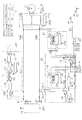
図1に示す回転機(モータジェネレータ10)は、車載主機であり、図示しない駆動輪に機械的に連結されている。モータジェネレータ10は、パワーコントロールユニット12に接続されている。詳しくは、パワーコントロールユニット12は、インバータ12aおよびこれを駆動する駆動制御部12bを備えており、モータジェネレータ10は、インバータ12aに接続されている。そして、インバータ12aは、システムメインリレーSMRを介して主機バッテリBmに接続されている。
"Overview of the system"
A rotating machine (motor generator 10) shown in FIG. 1 is an on-vehicle main machine, and is mechanically coupled to drive wheels (not shown). The
主機バッテリBmは、車体に対して絶縁されている。詳しくは、主機バッテリBmの正極電位および負極電位の中央値が車体電位とされている。これは、たとえば主機バッテリBmの正極および負極間に一対の抵抗体を接続し、それら抵抗体の接続点を車体に接続することで実現することができる。ここで、抵抗体は、主機バッテリBmと車体との絶縁要求に応じた抵抗値に設定される。主機バッテリBmは、電池セルの直列接続体としての組電池である。ここで、電池セルとして、本実施形態では、リチウムイオン2次電池を想定している。 Main machine battery Bm is insulated from the vehicle body. Specifically, the median value of the positive electrode potential and the negative electrode potential of main battery Bm is the vehicle body potential. This can be realized, for example, by connecting a pair of resistors between the positive electrode and the negative electrode of the main battery Bm and connecting the connection points of these resistors to the vehicle body. Here, the resistance body is set to a resistance value according to the insulation requirement between the main engine battery Bm and the vehicle body. Main battery Bm is an assembled battery as a series connection body of battery cells. Here, in this embodiment, a lithium ion secondary battery is assumed as the battery cell.
主機バッテリBmの状態(各電池セルの状態)は、電池ECU14によって監視、および調整される。すなわち、電池ECU14では、電池セルの過充電、過放電の有無を監視するとともに、電池セルの充電率(SOC)を均等化する処理を行なう。これは、リチウムイオン2次電池が、過充電、過放電によって信頼性の低下を招く懸念があるためになされるものである。なお、充電率とは、満充電電荷量に対する実際の電荷量の比率のことである。
The state of the main battery Bm (the state of each battery cell) is monitored and adjusted by the
主機バッテリBmの正極および負極は、チャージリレーCHRを介して、外部の系統電源(外部電源)からの電力を主機バッテリBmに充電するための充電ユニット20に接続される。充電ユニット20は、充電回路を備えている。充電回路において、外部電源からの電力は、整流回路21において直流電力に変換された後、PFC22回路を介してブリッジ回路23に入力される。ブリッジ回路23は、直流電力を交流電力に変換してトランス24の1次側コイルに印加する。一方、トランス24の2次側コイルには、整流回路25が接続されており、これにより、トランス24の2次側コイルから出力される交流電力が直流電力に変換される。整流回路25の出力電力は、フィルタ26によって平滑化された後、チャージリレーCHRを介して主機バッテリBmに入力される。
The positive and negative electrodes of main battery Bm are connected to
ここで、充電ユニット20は、駆動制御部27によってPFC回路22やブリッジ回路23のスイッチング素子を電子操作することで、充電制御を行なう。
Here, the
主機バッテリBmは、システムメインリレーSMRを介してコンバータユニット50に接続されている。詳しくは、コンバータユニット50は、DCDCコンバータ50aおよび駆動制御部50bを備えており、主機バッテリBmは、DCDCコンバータ50aの1次側に接続されている。DCDCコンバータ50aの2次側には、補機バッテリBaが接続されている。補機バッテリBaは、その満充電時における充電エネルギ量(最大蓄電量)が主機バッテリBmと比較して小さいものである。また、補機バッテリBaは、その基準電位(負極電位)が車体電位とされている。なお、補機バッテリBaとしては、たとえば鉛蓄電池を用いればよい。
Main machine battery Bm is connected to
上記DCDCコンバータ50aとして、本実施形態では、主機バッテリBmから補機バッテリBaへの電力の供給が可能であって且つ逆方向の電力の供給ができないもの(降圧コンバータ)を想定している。ちなみに、図では、DCDCコンバータ50aの1次側にスイッチング素子の記号を記載して且つ、2次側にダイオードの記号を記載しているが、これは上記電力の流通可能な方向を模式的に表現したものであり、実際の回路構成を限定する意図はない。 In the present embodiment, the DCDC converter 50a is assumed to be capable of supplying power from the main battery Bm to the auxiliary battery Ba and not capable of supplying power in the reverse direction (step-down converter). Incidentally, in the figure, the symbol of the switching element is described on the primary side of the DCDC converter 50a and the symbol of the diode is described on the secondary side, but this schematically shows the direction in which the power can flow. It is expressed and is not intended to limit the actual circuit configuration.
本実施形態では、太陽光パネル16を備えている。太陽光パネル16は、太陽光パネル用電子制御装置(SECU30)に接続されている。SECU30は、太陽光パネル16の出力電圧Vsを降圧して補機バッテリBaに供給する降圧ユニット34と、補機バッテリBaの電圧を昇圧して主機バッテリBmに供給する昇圧ユニット32とを備えている。ここで、降圧ユニット34は、降圧チョッパ回路36と、駆動制御部38とを備えている。ここで、降圧チョッパ回路36では、スイッチング素子36a、ダイオード36bおよびインダクタ36cを備え、スイッチング素子36aがオン状態となることで、太陽光パネル16から補機バッテリBaに電流が流れ、インダクタ36cのエネルギが漸増する。一方、スイッチング素子36aがオフ状態となることで、インダクタ36cに蓄えられたエネルギがダイオード36b、インダクタ36cおよび補機バッテリBaを備えるループ経路によって放出される。ここで、スイッチング素子36aは、駆動制御部38によって操作される。
In the present embodiment, a
一方、昇圧ユニット32は、昇圧回路32aと、昇圧回路32aを電子操作する駆動制御部32bとを備えている。本実施形態では、昇圧回路32aとして絶縁型のものを想定している。これは、補機バッテリBaがその負極電位を車体電位とする一方、主機バッテリBmが絶縁されていることに対応した設定である。昇圧回路32aは、ソーラ用リレーSLRを介して主機バッテリBmに接続されている。
On the other hand, the
本実施形態では、さらに、SECU30やパワーコントロールユニット12よりも、ユーザの指示に対してより上流に位置する上位の電子制御装置(UECU54)を備えている。UECU54は、車体電位を基準電位とし、補機バッテリBaを電源とするものである。ここで、補機バッテリBaの電力の投入は、第1電源スイッチ56によってなされる。第1電源スイッチ56は、ユーザの操作によってオン状態となり得るものである。ただし、一旦起動されると、SECU30自身によって、オン状態を維持可能なものである。さらに、ユーザによるオン操作がなされない車両の駐車時等においても、図示しないタイマによって周期的にオン状態としうるものである。
In the present embodiment, a higher-level electronic control unit (UCCU 54) is further provided upstream of the
UECU54は、第2電源スイッチ58を電子操作する機能を有する。第2電源スイッチ58は、電池ECU14や、充電ユニット20、SECU30、およびコンバータユニット50に対する補機バッテリBaの電力の供給および遮断を切り替えるものである。図では、電池ECU14や、充電ユニット20の駆動制御部27、昇圧ユニット32の駆動制御部32b、コンバータユニット50の駆動制御部50bに、第2電源スイッチ58を介して補機バッテリBaの電力が供給可能なことが図示されている。
The
なお、電池ECU14については、実際にはその低圧系(車体を基準電位とする系)に属する部分に第2電源スイッチ58を介して補機バッテリBaの電力が供給される。すなわち、電池ECU14は、主機バッテリBmに接続される部分である高圧系を構成する部分と、低圧系を構成する部分とを備える。ここで、高圧系を構成する部分については、主機バッテリBmを電源とすればよい。この場合、第2電源スイッチ58によって補機バッテリBaの電力の供給が遮断されたとしても、高圧系を構成する部分については主機バッテリBmによる電力の供給がなされうる。もっとも、高圧系を構成する部分についても、たとえば低圧系からの電力を絶縁コンバータを介して供給するなどすることも可能である。
It should be noted that the
ちなみに、充電ユニット20や、SECU30、およびコンバータユニット50等に対する補機バッテリBaの電力の遮断(電源の遮断)とは、これらを構成する全ての電子機器に対する電力の遮断を必ずしも意味しない。これは、たとえば、コンバータユニット50内の駆動制御部50bに、第2電源スイッチ58の状態にかかわらず、給電状態が常時維持されるメモリ(バックアップRAM)を備える場合によって説明される。すなわちこの場合、第2電源スイッチ58のオフ操作によって、駆動制御部50bを構成する大部分の電子機器については、電力供給が実質上遮断されるものの、駆動制御部50bが備えるバックアップRAMについては電力の供給が継続される。
Incidentally, the interruption of the power of the auxiliary battery Ba to the charging
UECU54は、上記パワーコントロールユニット12(駆動制御部12b)のための電源スイッチである第3電源スイッチを電子操作する機能をも有するが、このスイッチについては、その記載を省略した。
The
ここで、第2電源スイッチ58がオン操作されることによる第2電源は、図中、右上に記載したように、外部電源からの充電処理時である充電モード(charge)と、走行モード(driving)との双方において投入される。これに対し、第3電源スイッチのオン操作に
よる第3電源は、走行モードにおいて投入されるものの、充電モードにおいては投入されない。
Here, as described in the upper right in the figure, the second power source by turning on the
「太陽光パネルによる主機バッテリの充電処理」
上記太陽光パネル16は、走行時であるか、駐車時であるかに関わらず発電が可能なものである。このため、本実施形態では、駐車時においても太陽光パネル16の発電電力を主機バッテリBmに充電する。ここで、本実施形態では、主機バッテリBmの充電に際し、太陽光パネル16の発電電力を、降圧ユニット34を用いて一旦補機バッテリBaに充電する。これは、太陽光パネル16の発電電力の充電効率を向上させるための設定である。
“Charging the main battery with solar panels”
The
すなわち、主機バッテリBmを充電するに際しては、電池ECU14等を起動する必要が生じる。このため、第2電源スイッチ58をオン操作することが要求される。そして、この場合、電池ECU14のみならず、充電ユニット20や、コンバータユニット50等の電子機器も起動され、主機バッテリBmの充電処理期間においては、それら電子機器によって電力が消費される。一方、太陽光パネル16の発電電力は、天候等に依存し、その最大発電電力自体は、上記電子機器による消費電力よりも大きいものの、天候等によっては太陽光パネル16の発電電力が上記電子機器による消費電力以下となるおそれがある。このため、太陽光パネル16の発電電力を主機バッテリBmに充電すべく第2電源を投入する場合には、車両内の蓄電エネルギ総量がかえって減少するおそれすら生じうる。
That is, when charging main battery Bm,
このため、本実施形態では、太陽光パネル16の発電電力を補機バッテリBaに一旦充電する。この際、第2電源を投入しなくてもよいように、降圧ユニット34の電源を、太陽光パネル16の出力電圧Vsに基づき投入されるようにする。すなわち、降圧ユニット34の駆動制御部38には、局所電源スイッチ42を介して補機バッテリBaの電力が供給可能な設定とする。そして、局所電源スイッチ42は、太陽光パネル16の出力電圧Vsと規定電圧Vrefとの大小を比較するコンパレータ40の出力信号によって、操作可能とする。詳しくは、局所電源スイッチ42は、太陽光パネル16の出力電圧Vsが規定電圧Vref以上となることで、オン操作される。なお、コンパレータ40は、本実施形態において、判断手段を構成し、降圧ユニット34は、本実施形態において第1充電処理手段を構成する。
For this reason, in this embodiment, the auxiliary battery Ba is temporarily charged with the generated power of the
そして、UECU54では、上述したタイマによって周期的に起動される都度、補機バッテリBaの端子電圧Vaを検出する電圧センサ52の検出値を取り込み、これに基づき、太陽光パネル16の発電電力の充電量を把握する。そして充電量が大きくなることで、第2電源スイッチ58を投入し、補機バッテリBaの電力を昇圧ユニット32を介して主機バッテリBmに充電する。なお、昇圧ユニット32は、本実施形態において昇圧手段を構成する。
Then, each time it is periodically started by the above-described timer, the
図2に、本実施形態にかかる主機バッテリBmの充電処理の手順を示す。この処理は、駐車時において、UECU54が周期的に起動される都度、および起動されている期間において所定周期で実行される。
FIG. 2 shows a procedure for charging the main battery Bm according to the present embodiment. This process is executed every time the
この一連の処理では、まずステップS10において、補機バッテリBaの端子電圧Vaが充電開始閾値VthH以上であるか否かを判断する。この処理は、補機バッテリBaへの太陽光パネル16の発電電力の充電量が、主機バッテリBmへの充電にとって十分な値となったか否かを判断するためのものである。ここでは、通常の車両の停車時における補機バッテリBaの端子電圧に、太陽光パネル16の発電電力の充電量が十分となることで上昇する量を加算した値を充電開始閾値VthHとすればよい。
In this series of processes, first, in step S10, it is determined whether or not the terminal voltage Va of the auxiliary battery Ba is equal to or higher than the charging start threshold value VthH. This process is for determining whether or not the charging amount of the generated power of the
そして充電開始閾値VthH以上である場合、ステップS12において、第2電源をオンし、ソーラ用リレーSLRを閉操作し、主機バッテリBmの充電を指令する。これは、昇圧ユニット32の駆動制御部32bや電池ECU14に指令信号を出力することで実現することができる。この処理は、本実施形態における第2充電処理手段による処理である。ちなみに、ステップS12の処理がなされると、UECU54は、常時電源が投入された状態となる。このため、起動状態において、ステップS10の処理が所定周期でなされることとなる。
If it is equal to or higher than the charging start threshold value VthH, in step S12, the second power source is turned on, the solar relay SLR is closed, and charging of the main battery Bm is commanded. This can be realized by outputting a command signal to the
そして、ステップS10において否定判断される場合、ステップS14において、補機バッテリBaの端子電圧Vaが充電終了閾値VthL以下であるか否かを判断する。この処理は、主機バッテリBmへの充電を終了するか否かを判断するためのものである。そして、ステップS14において肯定判断される場合、ステップS16において、第2電源スイッチ58をオフ操作し、ソーラ用リレーSLRを開操作する。
If a negative determination is made in step S10, it is determined in step S14 whether or not the terminal voltage Va of the auxiliary battery Ba is equal to or lower than the charging end threshold value VthL. This process is for determining whether or not charging of the main battery Bm is to be terminated. If an affirmative determination is made in step S14, the
なお、ステップS16、S12の処理が完了する場合や、ステップS14において否定判断される場合には、この一連の処理を一旦終了する。ちなみに、ステップS16の処理が完了する場合、第1電源スイッチ56自体もオフ操作される。
In addition, when the process of step S16, S12 is completed, or when negative determination is made in step S14, this series of processes is once complete | finished. Incidentally, when the process of step S16 is completed, the
図3に、本実施形態の効果を示す。なお、図3では、太陽光パネル16の発電電力を昇圧ユニット32を用いて主機バッテリBmに直接充電する比較例と、本実施形態の場合とを対比して示す。
FIG. 3 shows the effect of this embodiment. In FIG. 3, a comparative example in which the power generated by the
比較例においては、太陽光パネル16の発電電力Psに応じて昇圧ユニット32の発電電力Pstが定まっている。そしてこの場合、電池ECU14や、充電ユニット20、SECU30、およびコンバータユニット50において電力が消費されるため、システム消費電力は常時大きいものとなる。
In the comparative example, the generated power Pst of the boosting
これに対し、本実施形態の場合、太陽光パネル16の発電電力Psに応じて降圧ユニット34の発電電力Pckが定まっている。そして、主機バッテリBmの充電処理がなされるとき以外では、システム消費電力は、降圧ユニット34や周期的に起動されるUECU54の消費電力に制限される。ちなみに、より正確には、たとえばコンバータユニット50や充電ユニット20等がバックアップRAM等を備える場合には、それらによる電力消費は生じている。またたとえば、UECU54が、ユーザが携帯する無線機器からの電波を受信可能なものとする場合、電波を受信するための機器のみは常時電力を消費することとなる。しかし主機バッテリBmの充電処理がなされない場合には、主機バッテリBmの充電処理時と比較して、電源が投入される電子機器の数が少ないために、消費電力が十分に小さい。このため、太陽光パネル16の発電電力の充電処理のために電源が投入される電子機器による消費電力を制限することができ、ひいては太陽光パネル16の発電電力の充電処理期間において車両内(主機バッテリBm,補機バッテリBa)に蓄電されるエネルギの上昇量を極力大きくすることができる。
On the other hand, in the case of the present embodiment, the generated power Pck of the step-down
このため、主機バッテリBmが充電されている期間において、太陽光パネル16の発電電力Psに対する主機バッテリBmの充電電力の比率として定義される充電効率は、本実施形態では、常時一定以上の値を維持できる。これに対し、比較例においては、太陽光パネル16の発電電力に応じて充電効率が変動する。
For this reason, the charging efficiency defined as the ratio of the charging power of the main battery Bm to the generated power Ps of the
以下、本実施形態の効果のいくつかを記載する。 Hereinafter, some of the effects of this embodiment will be described.
(1)太陽光パネル16の発電電力を主機バッテリBmに充電するに際し、一旦、補機バッテリBaに充電した。補機バッテリBaの充電に際しては、その状態を監視する手段を起動させる必要性等に乏しいことなどから、この際に電子機器によって消費される電力を低減することができる。
(1) When charging the power generated by the
(2)主機バッテリBmの充電処理に際して、第2電源を投入した。これにより、太陽光パネル16の発電電力を主機バッテリBmに充電するためになされる車載機器の設計変更を最小限に抑えることができる。このため、太陽光パネル16を車両のオプションとして提供する場合等において、オプションの提供価格を低下させやすい。
(2) When charging the main battery Bm, the second power source was turned on. Thereby, the design change of the vehicle equipment made in order to charge the main battery Bm with the electric power generation of the
(3)太陽光パネル16の発電電力を一旦蓄える蓄電手段を補機バッテリBaとした。これにより、追加部品数を削減することができる。
(3) The power storage means for temporarily storing the generated power of the
(4)補機バッテリBaへの充電に際し、電力変換回路(降圧チョッパ回路36)を備えた。これにより、太陽光パネル16の出力電圧Vsが変動する場合であっても、補機バッテリBaの充電電流を適正値とすることができる。
(4) A power conversion circuit (step-down chopper circuit 36) is provided when charging the auxiliary battery Ba. Thereby, even if the output voltage Vs of the
(5)第2充電処理手段を構成する制御手段(UECU54)が、周期的に起動されて補機バッテリBaの端子電圧Vaに基づき主機バッテリBmへの充電処理を行った。これにより、UECU54を常時起動状態とする場合と比較して、消費電力を低減することができる。
(5) The control means (UECU 54) constituting the second charge processing means is periodically activated to perform the charging process to the main battery Bm based on the terminal voltage Va of the auxiliary battery Ba. Thereby, power consumption can be reduced compared with the case where
(6)太陽光パネル16の出力電圧Vsが規定電圧Vref以上となる場合に降圧ユニット34を起動させて補機バッテリBaの充電処理を行った。これにより、主機バッテリBmの充電処理を行なう電子機器のうち、太陽光パネル16の出力電圧Vsが低い場合に電源が投入されている手段を、判断手段(コンパレータ40)等に限定することができる。
<第2の実施形態>
以下、第2の実施形態について、先の第1の実施形態との相違点を中心に図面を参照しつつ説明する。
(6) When the output voltage Vs of the
<Second Embodiment>
Hereinafter, the second embodiment will be described with reference to the drawings with a focus on differences from the first embodiment.
図4に、本実施形態にかかるシステム構成を示す。なお、図4において、先の図1に示した部材に対応するものについては、便宜上、同一の符号を付している。 FIG. 4 shows a system configuration according to the present embodiment. In FIG. 4, the same reference numerals are assigned to the members corresponding to those shown in FIG.
図示されるように、本実施形態では、降圧ユニット34を備えず、太陽光パネル16を補機バッテリBaに直接接続した。したがって、本実施形態にかかる第1充電処理手段は、太陽光パネル16の出力端子を補機バッテリBaの正極および負極に接続することで構成されるものである。この場合であっても、駐車時において、UECU54が周期的に起動される都度、先の図2に示した処理を実行すればよい。
<第3の実施形態>
以下、第3の実施形態について、先の第1の実施形態との相違点を中心に図面を参照しつつ説明する。
As illustrated, in this embodiment, the step-down
<Third Embodiment>
Hereinafter, the third embodiment will be described with reference to the drawings with a focus on differences from the first embodiment.
図5に、本実施形態にかかるシステム構成を示す。なお、図5において、先の図1に示した部材に対応するものについては、便宜上、同一の符号を付している。 FIG. 5 shows a system configuration according to the present embodiment. In FIG. 5, the same reference numerals are assigned to the members corresponding to those shown in FIG.
図示されるように、本実施形態では、太陽光パネル16にコンデンサ60を接続し、コンデンサ60を、昇圧ユニット32の昇圧回路32aの入力端子や、降圧ユニット34の降圧チョッパ回路36の入力端子に接続した。すなわち、本実施形態では、太陽光パネル16の発電電力を一旦充電するための蓄電手段を、コンデンサ60とした。なお、本実施形態にかかる第1充電処理手段は、太陽光パネル16の出力端子をコンデンサ60の正極および負極に接続することで構成されるものである。
<第4の実施形態>
以下、第4の実施形態について、先の第1の実施形態との相違点を中心に図面を参照しつつ説明する。
As shown in the figure, in this embodiment, a
<Fourth Embodiment>
Hereinafter, the fourth embodiment will be described with reference to the drawings with a focus on differences from the first embodiment.
図6に、本実施形態にかかるシステム構成を示す。なお、図6において、先の図1に示した部材に対応するものについては、便宜上、同一の符号を付している。 FIG. 6 shows a system configuration according to the present embodiment. In FIG. 6, the same reference numerals are assigned to the members corresponding to the members shown in FIG.
図示されるように、本実施形態では、SECU30が、昇圧ユニット32を備えない一方、コンバータユニット50内に双方向コンバータ50cを備えた。図では、双方向コンバータ50cによって補機バッテリBaから主機バッテリBmへの電力の伝送が可能であることを、双方向コンバータ50cの補機バッテリBa側の回路としてスイッチング素子を記載することで模式的に示した。ここには、実際の回路を限定する意図はない。
As shown in the figure, in this embodiment, the
こうした構成によれば、双方向コンバータ50を、太陽光パネル16の発電電力を主機バッテリBmに充電するための昇圧手段とすることができ、ひいては昇圧ユニット32やソーラ用リレーSLRを備える必要が生じない。
<第5の実施形態>
以下、第5の実施形態について、先の第1の実施形態との相違点を中心に図面を参照しつつ説明する。
According to such a configuration, the
<Fifth Embodiment>
Hereinafter, a fifth embodiment will be described with reference to the drawings, focusing on differences from the first embodiment.
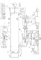
図7に、本実施形態にかかるシステム構成を示す。なお、図7において、先の図1に示した部材に対応するものについては、便宜上、同一の符号を付している。 FIG. 7 shows a system configuration according to the present embodiment. In FIG. 7, components corresponding to those shown in FIG. 1 are given the same reference numerals for convenience.
図示されるように、本実施形態では、補機バッテリBaに蓄えられた太陽光パネル16の発電電力を昇圧して主機バッテリBmに出力する昇圧手段を、充電ユニット20内の充電回路とする。詳しくは、補機バッテリBaをPFC回路22に接続する。PFC回路22は、たとえば昇圧チョッパ回路として構成可能であるため、これにより補機バッテリBaの電力を昇圧し、ブリッジ回路23、トランス24、整流回路25およびフィルタ26を介して主機バッテリBmに充電することができる。
As shown in the figure, in this embodiment, the boosting means for boosting the generated power of the
こうした設定によっても、太陽光パネル16の発電電力を主機バッテリBmに充電するために、昇圧ユニット32やソーラ用リレーSLRを備える必要が生じない。
Even with such setting, it is not necessary to provide the
また、本実施形態では、降圧ユニット34内の降圧回路を、昇圧チョッパ回路37と降圧チョッパ回路36との直列接続体とする。ここで、昇圧チョッパ回路37は、インダクタ37a、スイッチング素子37b、ダイオード37cおよびコンデンサ37dを備えている。そして、スイッチング素子37bがオン操作されることで、太陽光パネル16、インダクタ37a、およびスイッチング素子37bを備えるループ経路に電流が流れ、インダクタ37aの蓄積エネルギを漸増させる。その後、スイッチング素子37bがオフ操作されることで、太陽光パネル16、インダクタ37a、ダイオード37cおよびコンデンサ37dを備えるループ経路を介して、インダクタ37aの蓄積エネルギが放出される。
In the present embodiment, the step-down circuit in the step-down
こうした構成によれば、太陽光パネル16の発電効率を向上させることができる。すなわち、太陽光パネル16は、その出力電流に応じて発電効率が変動する特性を有する。このため、太陽光パネル16に降圧チョッパ回路36を直接接続する場合には、降圧チョッパ回路36のスイッチング素子36aがオン操作される都度、太陽光パネル16の出力電流がゼロから上昇し、オフ操作される都度、ゼロに減少するため、発電効率が低下する。これに対し、昇圧チョッパ回路37を太陽光パネル16の出力端子に接続する場合、昇圧チョッパ回路37のスイッチング素子37bのオン・オフ操作の期間にわたって太陽光パネル16の出力電流をゼロより大きい値に維持できる。しかも、インダクタ37aのインダクタンスの調整によって、昇圧チョッパ回路37の出力電流の変動量を調整可能であるため、発電効率を高い値に維持しやすい。
According to such a configuration, the power generation efficiency of the
具体的には、駆動制御部38では、太陽光パネル16の出力電圧Vsを目標電圧にフィードバック制御すべく、補機バッテリBaに対する印加電圧を操作する。これは、昇圧チョッパ回路37のスイッチング素子37bや降圧チョッパ回路36のスイッチング素子36aのオン・オフ操作の1周期に対するオン時間の時比率の調整によって行なうことができる。この場合、太陽光パネル16の出力電力は、効率を良好なものとすることのできる値に落ち着く。
Specifically, the
このため、太陽光パネル16の発電電力の利用効率が向上する。特に、たとえば、局所電源スイッチ42によって電源が投入される電子機器(駆動制御部38等)による消費電力を太陽光パネル16の発電電力が上回る確率を向上させることができる。ちなみに、発電電力が上回ることを局所電源スイッチ42のオン条件とするように規定電圧Vrefを設定することは一般に困難である。
<第6の実施形態>
以下、第6の実施形態について、先の第1の実施形態との相違点を中心に図面を参照しつつ説明する。
For this reason, the utilization efficiency of the generated power of the
<Sixth Embodiment>
Hereinafter, the sixth embodiment will be described with reference to the drawings with a focus on differences from the first embodiment.
図8に、本実施形態にかかるシステム構成を示す。なお、図8において、先の図1に示した部材に対応するものについては、便宜上、同一の符号を付している。 FIG. 8 shows a system configuration according to the present embodiment. In FIG. 8, components corresponding to those shown in FIG. 1 are given the same reference numerals for the sake of convenience.
本実施形態では、充電ユニット20に接続され、外部電源の電力を降圧して補機バッテリBaに出力するコンバータユニット70を備える。コンバータユニット70は、補機用充電回路(DCDCコンバータ70a)と、これを駆動する駆動制御部70bとを備えている。DCDCコンバータ70aは、整流回路21の出力端子に接続され、整流回路21の出力電力を降圧して補機バッテリBaに印加する。なお、本実施形態では、DCDCコンバータ70aとして、双方向のコンバータを想定している。
In the present embodiment, a
また本実施形態では、太陽光パネル16の出力電圧Vsを昇圧してDCDCコンバータ70aに出力する昇圧ユニット80を備える。昇圧ユニット80は、昇圧回路80aと、昇圧回路80aを操作する駆動制御部80bとを備えている。昇圧回路80aは、太陽光パネル16の出力端子とDCDCコンバータ70aの入力端子との間に接続されている。ここで、昇圧回路80aは、DCDCコンバータ70aの入力電圧が、整流回路21によって印加される場合と昇圧回路80aによって印加される場合とで生じる差を低減するためのものである。特に、昇圧回路80aは、太陽光パネル16の出力電圧Vsを補機バッテリBaの端子電圧Vaよりも高い値にするものである。なお、昇圧回路80aとDCDCコンバータ70aとの間には、ダイオード64が接続されている。ダイオード64は、整流回路21側から昇圧回路80a側に電流が流れる事態を回避するためのものである。
Further, in the present embodiment, a boosting
上記昇圧ユニット80の駆動制御部80bと、コンバータユニット70の駆動制御部70bとには、ともに、太陽光パネル16の出力電圧Vsが規定電圧Vref以上となることで電源が投入される。すなわち、駆動制御部80bには、局所電源スイッチ80cを介して補機バッテリBaが接続されており、駆動制御部70bには、局所電源スイッチ70cを介して補機バッテリBaが接続されている。そして、局所電源スイッチ70c,80cは、コンパレータ40によってオン操作される。
Both the drive control unit 80b of the
ちなみに、駆動制御部70bは、第2電源スイッチ58がオン操作されることによっても電源が投入される。すなわち、本実施形態では、主機バッテリBmに太陽光パネル16の発電電力を充電するために、駆動制御部70bの電源を追加している。しかし、本実施形態における設計変更や部品の増加は十分に制限されている。なぜなら、主機バッテリBmに太陽光パネル16の発電電力を充電するために追加された部品は、昇圧ユニット80と、局所電源スイッチ70c等に限定されるからである。ここで、昇圧ユニット80の昇圧回路80aとしては、非絶縁型のコンバータを用いることができ、また昇圧ユニット80と充電ユニット20との間にリレーを設ける必要もない。なぜなら、充電ユニット20の充電回路がトランス24を備えるため、これが絶縁伝送手段となって太陽光パネル16側と主機バッテリBm側とを絶縁するためである。
Incidentally, the
なお、上記昇圧回路80aとしては、先の図7に示した昇圧チョッパ回路37とすればよい。もっとも、絶縁型コンバータとすることも可能ではある。
<第7の実施形態>
以下、第7の実施形態について、先の第1の実施形態との相違点を中心に図面を参照しつつ説明する。
The booster circuit 80a may be the
<Seventh Embodiment>
Hereinafter, the seventh embodiment will be described with reference to the drawings with a focus on differences from the first embodiment.
図9に、本実施形態にかかるシステム構成を示す。なお、図9において、先の図1に示した部材に対応するものについては、便宜上、同一の符号を付している。 FIG. 9 shows a system configuration according to the present embodiment. In FIG. 9, the same reference numerals are assigned to the members corresponding to those shown in FIG.
図示されるように、本実施形態では、補機バッテリBaの充放電電流を検出する電流センサ90を備えるとともに、降圧ユニット34内に、電流センサ90によって検出される電流を積算する積算回路92を備える。積算回路92によって積算された積算値Inは、UECU54に出力される。UECU54では、積算値Inに基づき主機バッテリBmの充電処理を行なう。
As shown in the figure, in the present embodiment, a
図10に、本実施形態にかかる主機バッテリBmの充電処理の手順を示す。この処理は、駐車時において、UECU54が周期的に起動される都度、および起動されている期間において所定周期で実行される。なお、図10において、先の図2に示した処理に対応するものについては、便宜上同一のステップ番号を付している。
FIG. 10 shows a procedure for charging the main battery Bm according to the present embodiment. This process is executed every time the
この一連の処理では、まずステップS10aにおいて、積算値Inが積算閾値Inth以上であるか否かを判断する。この処理は、先の図2のステップS10の処理に対応するものである。ここで積算値Inを用いることで、電流センサ90の検出誤差を無視すれば、端子電圧Vaを用いる場合と比較して、太陽光パネル16の発電電力の補機バッテリBaへの充電量を高精度に把握することができる。これは、第1に、端子電圧Vaが上記充電量に加えて充電に先立つ補機バッテリBaの充電率に依存するためである。第2に、端子電圧Vaが補機バッテリBaの充放電の履歴に依存した分極を生じるためである。
In this series of processing, first, in step S10a, it is determined whether or not the integrated value In is greater than or equal to the integrated threshold value Inth. This process corresponds to the process in step S10 of FIG. Here, if the detection value of the
なお、本実施形態では、ステップS16aにおいて、先の図2のステップS16の処理に加えて、積算回路92を初期化する処理をも行なう。これは、UECU54からSECU30に指令を出すことで行なうことができる。
<第8の実施形態>
以下、第8の実施形態について、先の第1の実施形態との相違点を中心に図面を参照しつつ説明する。
In the present embodiment, in step S16a, in addition to the processing in step S16 of FIG. 2, the processing for initializing the integrating
<Eighth Embodiment>
Hereinafter, the eighth embodiment will be described with reference to the drawings with a focus on differences from the first embodiment.
図11に、本実施形態にかかるシステム構成を示す。なお、図11において、先の図1に示した部材に対応するものについては、便宜上同一の符号を付している。 FIG. 11 shows a system configuration according to the present embodiment. In FIG. 11, the same reference numerals are given for the sake of convenience to those corresponding to the members shown in FIG. 1.
本実施形態では、先の第5の実施形態(図7)同様、降圧ユニット34内の降圧回路を、昇圧チョッパ回路37と降圧チョッパ回路36との直列接続体とする。そして、補機バッテリBaの充電に際して、太陽光パネル16の出力電圧Vsを目標電圧に制御する。ここで、本実施形態では、特に、降圧回路および太陽光パネル16間に、太陽光パネル16の出力電流を検出する電流センサ38aを備える。
In the present embodiment, the step-down circuit in the step-down
図12に、本実施形態にかかる主機バッテリBmの充電処理の手順を示す。この処理は、駐車時において、UECU54が周期的に起動される都度、および起動されている期間において所定周期で実行される。なお、図12において、先の図2に示した処理に対応するものについては、便宜上同一のステップ番号を付している。
FIG. 12 shows a procedure for charging the main battery Bm according to the present embodiment. This process is executed every time the
この一連の処理では、まずステップS10bにおいて、補機バッテリBaの端子電圧Vaが充電開始閾値VthH以上であることと、太陽光パネル16の出力電力Psが閾値電力Psth以上であることとの論理和が真であるか否かを判断する。この処理は、先の図2のステップS10の処理に対応するものである。ここで、本実施形態において、太陽光パネル16の出力電力Psが閾値電力Psth以上であることを主機バッテリBmの充電処理の実行条件としたのは、ソーラ用リレーSLRの消耗を抑制するためである。
In this series of processing, first, in step S10b, the logical sum of the terminal voltage Va of the auxiliary battery Ba being equal to or higher than the charging start threshold VthH and the output power Ps of the
すなわち、補機バッテリBaの端子電圧Vaが充電開始閾値VthH以上となる場合に限って主機バッテリBmの充電処理を開始する場合、主機バッテリBmの充電処理に伴って補機バッテリBaの端子電圧が低下すると、主機バッテリBmの充電処理を一旦終了することとなる。そしてこの場合には、絶縁の観点からソーラ用リレーSLRが一旦開操作されるのが通例である。しかし、太陽光パネル16の出力電力Psが大きい場合、補機バッテリBaの端子電圧Vaが充電開始閾値VthH以上の値に上昇するまでに要する時間が短くなる。したがって、ソーラ用リレーSLRの開閉頻度が高くなり、ひいては、ソーラ用リレーSLRの消耗が促進されるおそれがある。
That is, when the charging process of the main battery Bm is started only when the terminal voltage Va of the auxiliary battery Ba is equal to or higher than the charging start threshold VthH, the terminal voltage of the auxiliary battery Ba is increased along with the charging process of the main battery Bm. If it falls, the charge process of the main battery Bm will be once complete | finished. In this case, the solar relay SLR is usually opened once from the viewpoint of insulation. However, when the output power Ps of the
なお、太陽光パネル16の出力電力Psは、太陽光パネル16の出力電圧Vsと、電流センサ38aによって検出される太陽光パネル16の出力電流との積として算出すればよい。
The output power Ps of the
<第9の実施形態>
以下、第9の実施形態について、先の第1の実施形態との相違点を中心に図面を参照しつつ説明する。
<Ninth Embodiment>
Hereinafter, the ninth embodiment will be described with reference to the drawings with a focus on differences from the first embodiment.
図13に、本実施形態にかかるシステム構成を示す。なお、図13において、先の図1に示した部材に対応するものについては、便宜上同一の符号を付している。 FIG. 13 shows a system configuration according to the present embodiment. In FIG. 13, the same reference numerals are given for the sake of convenience to those corresponding to the members shown in FIG. 1.
図示されるように、本実施形態では、降圧ユニット34内に降圧コンバータ39を備えている。降圧コンバータ39は、たとえば先の図7に示した昇圧チョッパ回路37および降圧チョッパ回路36を備えた回路とすればよい。駆動制御部38では、電流センサ38aによって検出される太陽光パネル16の出力電流と、太陽光パネル16の出力電圧Vsとを入力とし、最大電力点追従制御を行うべく、降圧コンバータ39を操作する。なお、駆動制御部38は、本実施形態において、最大電力点追従制御手段を構成する。
As illustrated, in this embodiment, a step-
また、本実施形態では、降圧コンバータ39から出力される太陽光パネル16の発電電力が一旦蓄えられる蓄電手段を、補機バッテリBaに代えてサブバッテリBsbとする。ここでサブバッテリBsbは、ニッケル水素2次電池である。これは、発電電力を一旦蓄える蓄電手段の信頼性を向上させたり、太陽光パネル16の発電電力の利用効率を向上させたりすることを狙ったものである。すなわち、補機バッテリBaは、鉛蓄電池であるが故に、充電率の変動によって信頼性が低下しやすい。このため、太陽光パネル16の発電電力を補機バッテリBaに一旦蓄え、これを主機バッテリBmに充電する処理を行う場合、補機バッテリBaの信頼性を維持する上では、主機バッテリBmへの一度の充電電力が小さくならざるを得ない。これに対し、ニッケル水素2次電池からなるサブバッテリBsbを用いるなら、補機バッテリBaと比較して充電率を大きく変動させることができるため、主機バッテリBmへの一度の充電電力量を増大させることができ、ひいてはソーラ用リレーSLRの開閉状態の切替頻度を低減することができる。
In the present embodiment, the power storage means for temporarily storing the generated power of the
そして、サブバッテリBsbと補機バッテリBaとの間にDCDCコンバータ100を介在させる。なお、DCDCコンバータ100は、実際にはコンバータ回路と駆動制御部とを備え、また、第2電源を電源とする。
Then,
図14に、本実施形態にかかる主機バッテリBmの充電処理の手順を示す。この処理は、駐車時において、UECU54が周期的に起動される都度実行される。
FIG. 14 shows a procedure for charging the main battery Bm according to the present embodiment. This process is executed every time the
この一連の処理では、まずステップS20において、サブバッテリBsbの充電率SOC(Bsb)が閾値SthH以上であるか否かを判断する。この処理は、サブバッテリBsbへの太陽光パネル16の発電電力の充電量が、主機バッテリBmの充電にとって十分な値となったか否かを判断するためのものである。そして、ステップS20において肯定判断される場合、ステップS22に移行する。
In this series of processes, first, in step S20, it is determined whether or not the charging rate SOC (Bsb) of the sub-battery Bsb is equal to or greater than a threshold value SthH. This process is for determining whether or not the charging amount of the generated power of the
ステップS22においては、第2電源スイッチ58をオン操作し、ソーラ用リレーSLRを閉状態とし、昇圧ユニット32の出力電力Pstの指令値Pst*を予め定められた値Pst0(>0)とする。さらに、この際、DCDCコンバータ100の出力電圧を指令値に制御する。ここで、指令値は、補機バッテリBaの充電率が、補機バッテリBaの信頼性の低下を招くおそれがある程度まで低下する場合の端子電圧よりも高い値に設定される。これにより、第2電源スイッチ58がオン状態とされることで車載電子機器の消費電力が増加し、補機バッテリBaの充電率が低下する状況下、これが過度に低下する事態を回避することができる。
In step S22, the
続くステップS24においては、主機バッテリBmの充電処理の継続時間をカウントするカウンタTをインクリメントする。続くステップS26では、サブバッテリBsbの充電率SOCsbが閾値SthL以下であることと、カウンタTが閾値Tth以上であることとの論理和が真であるか否かを判断する。この処理は、主機バッテリBmの充電処理を停止するか否かを判断するためのものである。ここで、閾値SthLは、サブバッテリBsbに蓄えられた発電電力が十分に放電されることで到達する充電率に設定されている。また、閾値Tthは、太陽光パネル16の発電電力が想定される最大値程度となる場合に、サブバッテリBsbに蓄えられた発電電力を十分に放電させるのに要する時間に設定される。ここで、閾値Tthを用いたのは、充電率SOCsbの算出誤差等によって主機バッテリBmの充電処理を誤って継続することで、サブバッテリBsbが過度に放電する事態を回避することを狙っている。
In the subsequent step S24, a counter T that counts the duration of the charging process of the main battery Bm is incremented. In the subsequent step S26, it is determined whether or not the logical sum of whether the charging rate SOCsb of the sub-battery Bsb is equal to or smaller than the threshold value SthL and that the counter T is equal to or larger than the threshold value Tth is true. This process is for determining whether or not to stop the charging process of the main battery Bm. Here, the threshold value SthL is set to a charging rate that is reached when the generated power stored in the sub-battery Bsb is sufficiently discharged. The threshold value Tth is set to a time required to sufficiently discharge the generated power stored in the sub-battery Bsb when the generated power of the
そして、ステップS26において肯定判断される場合、ステップS28において、第2電源スイッチ58をオフ操作し、ソーラ用リレーSLRを開状態とし、昇圧ユニット32の出力を停止させ、補機バッテリBaの給電を停止する。
If an affirmative determination is made in step S26, the
なお、ステップS28の処理が完了する場合や、ステップS20において否定判断される場合には、この一連の処理を一旦終了する。 When the process of step S28 is completed or when a negative determination is made in step S20, this series of processes is temporarily ended.
<第10の実施形態>
以下、第10の実施形態について、先の第1の実施形態との相違点を中心に図面を参照しつつ説明する。
<Tenth Embodiment>
Hereinafter, the tenth embodiment will be described with reference to the drawings with a focus on differences from the first embodiment.
図15に、本実施形態にかかる主機バッテリBmの充電処理の手順を示す。この処理は、駐車時において、UECU54が周期的に起動される都度、および起動されている期間において所定周期で実行される。なお、図15において、先の図14に示した処理に対応するものについては、便宜上同一のステップ番号を付している。
FIG. 15 shows a procedure for charging the main battery Bm according to the present embodiment. This process is executed every time the
この一連の処理では、ステップS26の処理が完了する場合、ステップS28aにおいて、先の図14のステップS28の処理に加えて、閾値Tthを、カウンタTの値にマージン量Δを加算した値とする処理を行う。この処理は、閾値Tthとしての適切な長さを学習する学習処理である。ここで、マージン量Δは、日照量の変動等に起因して今回のカウンタTの値が、次回の主機バッテリBmの充電処理に際して、サブバッテリBsbに蓄えられた発電電力を十分に放電する時間として適切な時間からずれうることに鑑みて設定される。 In this series of processes, when the process of step S26 is completed, in step S28a, in addition to the process of step S28 of FIG. 14, the threshold value Tth is a value obtained by adding the margin amount Δ to the value of the counter T. Process. This process is a learning process for learning an appropriate length as the threshold value Tth. Here, the margin amount Δ is the time during which the current value of the counter T is sufficiently discharged from the sub-battery Bsb during the next charging process of the main battery Bm due to fluctuations in the amount of sunlight. Is set in view of the fact that it can deviate from an appropriate time.
なお、閾値Tthとしては、デフォルト値を設けておき、主機バッテリBmの前回の充電処理から今回の充電処理までの時間間隔が長くなる場合には、学習値に代えてデフォルト値を採用するようにすることが望ましい。
<その他の実施形態>
なお、上記各実施形態は、以下のように変更して実施してもよい。
As the threshold value Tth, a default value is provided, and when the time interval from the previous charging process of the main battery Bm to the current charging process becomes longer, the default value is adopted instead of the learning value. It is desirable to do.
<Other embodiments>
Each of the above embodiments may be modified as follows.
「積算手段について」
上記第7の実施形態(図9)に例示したものに限らない。たとえば、積算回路92を、降圧ユニット34内に搭載する代わりに、これに対して外付けしてもよい。ただし、この場合であっても、積算回路92の電源は、第1電源や第2電源とは独立に投入可能なものとする。
"Accumulation means"
It is not restricted to what was illustrated to the said 7th Embodiment (FIG. 9). For example, the integrating
また、電流の検出値としては、電流センサ90の出力値を用いるものに限らない。たとえば、太陽光パネル16の出力電圧Vsと、補機バッテリBaの端子電圧Vaと、スイッチング素子36aのオン・オフの一周期に対するオン時間の時比率とから算出される電流量であってもよい。ただし、この場合、これら3つのパラメータを入力とし電流量を算出する手段の電源は、第1電源や第2電源とは独立に投入可能なものとする。
The detected current value is not limited to the output value of the
「第1充電処理手段について」
駆動制御部38の電源投入を、局所電源スイッチ42によって行なうものに限らない。たとえば、駆動制御部38の電源端子を太陽光パネル16の出力端子に接続することで、太陽光パネル16自体を電源とするものであってもよい。
“About the first charge processing means”
The power supply of the
「電力変換回路について」
上記第5の実施形態(図7)や第8の実施形態(図11)において、降圧ユニット34を昇圧回路として利用してもよい。これにより、太陽光パネル16の出力電圧Vsを一旦昇圧することで、太陽光パネル16の出力電圧Vsが補機バッテリBaの端子電圧Va以下である場合であっても補機バッテリBaの充電が可能となる。なお、補機バッテリBaへの充電処理の機会を増やす上では、入力電圧を昇圧して出力電圧とする機能と、入力電圧を降圧して出力電圧とする機能との双方を有することが望ましい。
"Power conversion circuit"
In the fifth embodiment (FIG. 7) and the eighth embodiment (FIG. 11), the step-down
「判断手段について」
たとえば、SECU34を周期的に起動する設定として且つ、SECU34が周期的に起動される都度、太陽光パネル16の出力電圧が規定電圧以上であるかを判断してもよい。またたとえば、UECU54が周期的に起動される都度、太陽光パネル16の出力電圧が規定電圧以上であるかを判断してもよい。
About judgment means
For example, as a setting for periodically starting the
「蓄電手段の充電開始条件について」
たとえば、判断手段によって規定電圧以上であると判断される場合であっても、主機バッテリBmの充電率が高い場合には太陽光パネル16の発電を禁止してもよい。
“Charging start conditions for power storage means”
For example, even when it is determined by the determining means that the voltage is equal to or higher than a specified voltage, power generation of the
また、判断手段を備えることは必須ではない。すなわちたとえば、太陽光パネル16の出力端子をレギュレータに接続し、その出力電圧を駆動制御部38に印加する構成としてもよい。またたとえば、ユーザが駆動制御部38の電源を操作可能とし、ユーザによって電源がオン操作される場合には、太陽光パネル16の出力電圧Vsの大小にかかわらず駆動制御部38をオン状態とし、補機バッテリBaの充電処理を行ってもよい。
Moreover, it is not essential to provide a determination means. That is, for example, the output terminal of the
「第2充電処理手段について」
a)主体について
先の第1、第7および第8の実施形態では、図2、図10、図12の処理をUECU54が行ったがこれに限らない。たとえば、SECU30が行ってもよい。
"About the 2nd charge processing means"
a) About the main body In the first, seventh and eighth embodiments, the processing of FIG. 2, FIG. 10, and FIG. For example, the
b)充電処理の終了判断について
補機バッテリBaの端子電圧Vaや積算値Inに基づき終了判断するものに限らない。たとえば、上記第7の実施形態(図9、図10)において、主機バッテリBmの各電池セルのSOCの上昇量が、積算回路92に基づき算出される補機バッテリBaの充電電荷量に基づき算出される規定量となることで、終了すると判断してもよい。なお、主機バッテリBmの各電池セルのSOCの上昇量は、電池ECU14によって算出すればよい。
b) Termination determination of the charging process It is not limited to the termination determination based on the terminal voltage Va of the auxiliary battery Ba and the integrated value In. For example, in the seventh embodiment (FIGS. 9 and 10), the SOC increase amount of each battery cell of the main battery Bm is calculated based on the charge amount of the auxiliary battery Ba calculated based on the
「第2充電処理手段による主機バッテリBmの充電時について」
この間、太陽光パネル16の発電を停止させるようにしてもよい。
“When charging the main battery Bm by the second charge processing means”
During this time, the power generation of the
「主機用充電回路について」
絶縁伝送手段としては、トランス24を備えるものに限らない。たとえば、先の図8に示すトランス24を、フライングキャパシタに代えてもよい。
“Charging circuit for main engine”
The insulated transmission means is not limited to the one provided with the
「補機用充電回路について」
上記第6の実施形態(図8)に例示したDCDCコンバータ70aに限らない。たとえば、双方向コンバータ70aに代えて、外部の商用電源側から補機バッテリBa側への電力の伝送が可能であって且つ、逆方向の電力の伝送ができないものであってもよい。
“Auxiliary charging circuit”
It is not limited to the DCDC converter 70a illustrated in the sixth embodiment (FIG. 8). For example, instead of the bidirectional converter 70a, power transmission from the external commercial power supply side to the auxiliary battery Ba side is possible, but power transmission in the reverse direction may not be possible.
「主機バッテリBmについて」
リチウムイオン2次電池に限らない。これ以外のものであっても、充電率や端子電圧についての制約を満たさない場合に信頼性の低下を招くおそれがある場合には、電池ECU14を起動させる必要が生じるため、本発明の適用が特に有効である。
“Main battery Bm”
It is not limited to a lithium ion secondary battery. Even if it is other than this, it is necessary to start the
車体に対して絶縁されたものに限らない。たとえば大電流を出力可能とするかわりに端子電圧を低下させることで、負極電位を車体電位としてもよい。この場合、主機バッテリBmとの間で電力の授受を行なう電力変換回路として、絶縁型コンバータを用いなくてもよい。 It is not restricted to what was insulated with respect to the vehicle body. For example, the negative electrode potential may be used as the vehicle body potential by reducing the terminal voltage instead of enabling a large current to be output. In this case, an insulated converter may not be used as a power conversion circuit that transfers power to and from main battery Bm.
「補機バッテリについて」
鉛蓄電池に限らず、たとえばニッケル水素2次電池であってもよい。
“Auxiliary battery”
For example, a nickel hydride secondary battery may be used.
「サブバッテリについて」
ニッケル水素2次電池に限らず、たとえばリチウムイオン2次電池であってもよい。
“Sub-battery”
For example, a lithium ion secondary battery may be used.
「そのほか」
車両の走行時であっても、太陽光パネル16の発電電力を補機バッテリBa等の蓄電手段に直接充電するよりも、電力変換回路を用いて充電した方が、発電効率を向上させることができるなど、発電制御の制御性を向上させることができる。
"others"
Even when the vehicle is running, the power generation efficiency can be improved by charging using the power conversion circuit rather than directly charging the power generated by the
10…モータジェネレータ(回転機の一実施形態)、16…太陽光パネル、Bm…主機バッテリ、Ba…補機バッテリ(蓄電手段の一実施形態)。
DESCRIPTION OF
Claims (13)
前記太陽光発電手段と前記蓄電手段との間に介在する電力変換回路(36,37,80a)と、
前記電力変換回路を操作することで、前記太陽光発電手段の発電電力を前記蓄電手段に一旦充電する第1充電処理手段(38)と、
前記蓄電手段の電圧を昇圧して前記主機バッテリに出力する昇圧手段(32a,50,22)と、
前記昇圧手段を操作することで、前記蓄電手段に蓄電された前記発電電力を前記主機バッテリに充電する第2充電処理手段(32b,27)と、
を備え、
前記第2充電処理手段によって前記主機バッテリが充電される場合に電源が投入される電子機器に、前記第1充電処理手段によって前記蓄電手段が充電されて且つ前記第2充電処理手段による主機バッテリの充電がなされていない場合に電源が遮断状態となるものを含めることで、前記第1充電処理手段によって前記蓄電手段が充電されて且つ前記第2充電処理手段による主機バッテリの充電がなされていない場合における車載電子機器の消費電力を、前記第2充電処理手段によって前記主機バッテリが充電される場合における車載電子機器の消費電力よりも小さくしたことを特徴とする車載充電制御装置。 A main battery (Bm) as a means for storing electrical energy supplied to the rotating machine (10) that is the in-vehicle main machine, a power storage means (Ba, Bsb) having a smaller maximum power storage capacity than the main battery, and a solar power generation means ( 16)
A power conversion circuit (36, 37, 80a) interposed between the solar power generation means and the power storage means;
A first charge processing means (38) for temporarily charging the power storage means with the power generated by the solar power generation means by operating the power conversion circuit;
Boosting means (32a, 50, 22) for boosting the voltage of the power storage means and outputting it to the main battery;
Second charge processing means (32b, 27) for charging the main battery with the generated power stored in the power storage means by operating the boosting means;
Equipped with a,
When the main battery is charged by the second charge processing means, an electronic device that is turned on is charged with the power storage means by the first charge processing means and the main battery of the main battery by the second charge processing means. Including the case where the power source is cut off when charging is not performed, so that the power storage unit is charged by the first charging processing unit and the main battery is not charged by the second charging processing unit The vehicle-mounted charging control device according to claim 1, wherein the power consumption of the vehicle-mounted electronic device is made smaller than the power consumption of the vehicle-mounted electronic device when the main battery is charged by the second charging processing means .
前記第2充電処理手段は、車両の停止時において、前記蓄電手段に蓄電された前記発電電力を前記主機バッテリに充電するものであることを特徴とする請求項1記載の車載充電制御装置。 The first charge processing means is for temporarily charging the power storage means with the power generated by the solar power generation means when the vehicle is stopped.
The second charging process means, when the vehicle is stopped, the in-vehicle charge control device according to claim 1, wherein the der Rukoto which charges the power generating power stored in said storage means to the main battery.
前記積算手段による積算結果に基づき、前記第2充電処理手段による前記主機バッテリに充電する処理を行なうことを特徴とする請求項1〜7のいずれか1項に記載の車載充電制御装置。 The first charging processing means includes an integrating means (92) for integrating the amount of charging current to the power storage means,
The in-vehicle charging control device according to any one of claims 1 to 7 , wherein a process of charging the main unit battery by the second charging processing unit is performed based on an integration result by the integrating unit.
前記第1充電処理手段は、前記判断手段によって規定電圧以上であると判断されることで、前記蓄電手段の充電を開始することを特徴とする請求項1〜8のいずれか1項に記載の車載充電制御装置。 A judgment means (40) for judging whether the output voltage of the solar power generation means is equal to or higher than a specified voltage;
The said 1st charge process means starts charge of the said electrical storage means by being judged that it is more than regulation voltage by the said judgment means, The any one of Claims 1-8 characterized by the above-mentioned. In-vehicle charging control device.
該外部電源充電手段は、昇圧回路(22)を備え、
前記昇圧手段を前記外部電源充電手段の昇圧回路としたことを特徴とする請求項1〜9のいずれか1項に記載の車載充電制御装置。 An external power source charging means (20) for charging the main unit battery with the power of the external power source by being connected to an external power source;
The external power supply charging means includes a booster circuit (22),
Vehicle charge control device according to any one of claims 1 to 9, characterized in that said boosting means and a booster circuit of the external power supply charging means.
前記主機バッテリと前記補機バッテリとの間の電力の授受を仲介する双方向コンバータ(50c)を備え、
前記昇圧手段を前記双方向コンバータとしたことを特徴とする請求項1〜9のいずれか1項に記載の車載充電制御装置。 The power storage means is an in-vehicle auxiliary battery,
A bi-directional converter (50c) that mediates transfer of electric power between the main battery and the auxiliary battery;
Vehicle charge control device according to any one of claims 1 to 9, characterized in that said boosting means and said bi-directional converter.
外部電源に接続されることで該外部電源の電力を前記主機バッテリに充電するための主機用充電回路(20)と、
前記外部電源の電力を前記補機バッテリに充電する補機用充電回路(70)とを備え、
前記主機用充電回路は、1次側および2次側を絶縁しつつ電力を伝送する絶縁伝送手段であり、
前記補機用充電回路は、前記絶縁伝送手段の1次側の電圧を降圧して前記補機バッテリに印加する機能を有し、
前記第1充電処理手段は、前記太陽光発電手段の出力電圧を昇圧して前記補機用充電回路側に印加する昇圧回路(80a)と、前記補機用充電回路と、前記昇圧回路および前記補機用充電回路を電子操作する手段(80b,70b)とを備え、
前記昇圧手段は、前記補機用充電回路および前記絶縁伝送手段を備えることを特徴とする請求項1〜9のいずれか1項に記載の車載充電制御装置。 The power storage means is an in-vehicle auxiliary battery,
A main unit charging circuit (20) for charging the main unit battery with electric power of the external power source by being connected to an external power source;
An auxiliary charging circuit (70) for charging the auxiliary battery with electric power from the external power source,
The main circuit charging circuit is an insulating transmission means for transmitting power while insulating the primary side and the secondary side,
The auxiliary charging circuit has a function of stepping down the voltage on the primary side of the insulating transmission means and applying it to the auxiliary battery,
The first charging processing means boosts the output voltage of the solar power generation means and applies the boosted voltage to the auxiliary charging circuit side, the auxiliary charging circuit, the boosting circuit, and the Means (80b, 70b) for electronically operating the auxiliary charging circuit,
It said boosting means, vehicle charging control apparatus according to any one of claims 1 to 9, further comprising a charging circuit and the insulating transmission means for the auxiliary machine.
Priority Applications (4)
| Application Number | Priority Date | Filing Date | Title |
|---|---|---|---|
| JP2012197864A JP5673633B2 (en) | 2012-06-01 | 2012-09-07 | In-vehicle charging controller |
| DE102013209954A DE102013209954A1 (en) | 2012-06-01 | 2013-05-28 | Charging control for a vehicle |
| US13/903,383 US9444285B2 (en) | 2012-06-01 | 2013-05-28 | Charge controller for vehicle |
| CN201310213668.XA CN103457312B (en) | 2012-06-01 | 2013-05-31 | Charge controller for vehicle |
Applications Claiming Priority (3)
| Application Number | Priority Date | Filing Date | Title |
|---|---|---|---|
| JP2012125977 | 2012-06-01 | ||
| JP2012125977 | 2012-06-01 | ||
| JP2012197864A JP5673633B2 (en) | 2012-06-01 | 2012-09-07 | In-vehicle charging controller |
Publications (2)
| Publication Number | Publication Date |
|---|---|
| JP2014007937A JP2014007937A (en) | 2014-01-16 |
| JP5673633B2 true JP5673633B2 (en) | 2015-02-18 |
Family
ID=49579735
Family Applications (1)
| Application Number | Title | Priority Date | Filing Date |
|---|---|---|---|
| JP2012197864A Active JP5673633B2 (en) | 2012-06-01 | 2012-09-07 | In-vehicle charging controller |
Country Status (4)
| Country | Link |
|---|---|
| US (1) | US9444285B2 (en) |
| JP (1) | JP5673633B2 (en) |
| CN (1) | CN103457312B (en) |
| DE (1) | DE102013209954A1 (en) |
Cited By (2)
| Publication number | Priority date | Publication date | Assignee | Title |
|---|---|---|---|---|
| JP2014117000A (en) * | 2012-12-06 | 2014-06-26 | Denso Corp | Charge control apparatus |
| US11628736B2 (en) | 2019-11-21 | 2023-04-18 | Toyota Jidosha Kabushiki Kaisha | Solar charging system and vehicle |
Families Citing this family (44)
| Publication number | Priority date | Publication date | Assignee | Title |
|---|---|---|---|---|
| CN102118043B (en) * | 2009-12-31 | 2013-12-04 | 比亚迪股份有限公司 | Solar charger for charging power battery |
| CN107171582B (en) | 2011-09-29 | 2019-03-29 | 株式会社大亨 | Signal processing apparatus, filter, control circuit, inverter and converter system |
| DK2575252T3 (en) | 2011-09-29 | 2018-10-08 | Daihen Corp | Signal processor, filter, power converter for power converter circuit, connection inverter system and PWM inverter system |
| JP6008668B2 (en) * | 2012-09-19 | 2016-10-19 | シャープ株式会社 | Power conversion device, power storage system, and power storage method |
| US9821666B2 (en) * | 2013-05-17 | 2017-11-21 | Toyota Jidosha Kabushiki Kaisha | Charge control device using an in-vehicle solar cell |
| JP6278715B2 (en) * | 2014-01-22 | 2018-02-14 | 株式会社デンソー | Charger |
| US20160344231A1 (en) * | 2014-05-30 | 2016-11-24 | Randolph Earl Bridwell | Charge Controller with Wired or Wireless Communications Network |
| BE1022153B1 (en) * | 2014-08-07 | 2016-02-19 | Fcl Holding Nv | METHOD FOR QUICK CHARGING OF ACID BATTERIES |
| KR101516193B1 (en) * | 2015-01-08 | 2015-05-04 | 주식회사 미지에너텍 | Apparatus for controlling solar charging and method therefor |
| DE102015000577A1 (en) * | 2015-01-16 | 2016-07-21 | Audi Ag | Method for operating a motor vehicle with a solar device and motor vehicle |
| DE102015000593A1 (en) * | 2015-01-16 | 2016-07-21 | Audi Ag | High voltage battery for a motor vehicle and motor vehicle |
| DE102015102410A1 (en) * | 2015-02-20 | 2016-08-25 | Vossloh Kiepe Gmbh | Battery assembly for a vehicle |
| KR102381085B1 (en) * | 2015-02-27 | 2022-04-01 | 삼성전자주식회사 | Dc-dc converter, charging integrated circuit and electronic device having the same and battery charging method thereof |
| JP6586290B2 (en) * | 2015-04-23 | 2019-10-02 | 本田技研工業株式会社 | Power storage control device, transport equipment, and power storage control method |
| US10031567B2 (en) * | 2015-06-09 | 2018-07-24 | Microsoft Technology Licensing, Llc | Offline battery management in a device |
| US10099567B2 (en) * | 2015-10-05 | 2018-10-16 | Ford Global Technologies, Llc | Vehicle auxiliary battery charging system |
| DE102015224092B4 (en) * | 2015-12-02 | 2021-05-12 | Volkswagen Aktiengesellschaft | Electrical high-voltage system and method for charging a high-voltage battery of an electrical high-voltage system |
| US10245960B2 (en) * | 2016-03-17 | 2019-04-02 | Denso International America, Inc. | Electric power converter device |
| US10615465B2 (en) * | 2016-09-23 | 2020-04-07 | Artisan Vehicle Systems Inc. | Battery management system |
| JP6551358B2 (en) * | 2016-10-13 | 2019-07-31 | トヨタ自動車株式会社 | vehicle |
| EP3531528B1 (en) * | 2016-10-21 | 2021-10-06 | Nissan Motor Co., Ltd. | Power supply system and method for controlling same |
| CN108092371B (en) * | 2016-11-15 | 2020-04-03 | 华为技术有限公司 | Charging and discharging device |
| JP6504144B2 (en) * | 2016-11-17 | 2019-04-24 | トヨタ自動車株式会社 | vehicle |
| JP6624128B2 (en) * | 2017-03-14 | 2019-12-25 | トヨタ自動車株式会社 | Car |
| US20190047432A1 (en) * | 2017-08-14 | 2019-02-14 | Sheila Clark | Secondary solar charging battery system for use with a recreational vehicle |
| KR102417897B1 (en) * | 2017-09-07 | 2022-07-07 | 현대자동차주식회사 | Apparatus for controlling charging in environment-friendly vehicle, system having the same and method thereof |
| US11894715B2 (en) | 2017-09-07 | 2024-02-06 | Toyota Jidosha Kabushiki Kaisha | Charge control system and charge control method |
| JP6953997B2 (en) * | 2017-09-07 | 2021-10-27 | トヨタ自動車株式会社 | Charge control system and charge control method |
| CN107911025A (en) * | 2017-11-21 | 2018-04-13 | 奇瑞汽车股份有限公司 | Voltage changer and its control method, automobile for electric automobile |
| CN111566890B (en) * | 2017-12-11 | 2023-02-17 | 松下知识产权经营株式会社 | Vehicle-mounted power supply device |
| KR102440522B1 (en) * | 2017-12-28 | 2022-09-06 | 현대자동차주식회사 | Apparatus and Method for controlling charge capacity variably using external energy source |
| JP6969391B2 (en) * | 2018-01-09 | 2021-11-24 | オムロン株式会社 | Energy storage control device |
| KR102518182B1 (en) * | 2018-02-14 | 2023-04-07 | 현대자동차주식회사 | Apparatus for controlling converter of green car and method thereof |
| CN110661042A (en) * | 2018-06-29 | 2020-01-07 | 宁德时代新能源科技股份有限公司 | Battery management system and energy storage power station |
| KR20200095001A (en) * | 2019-01-31 | 2020-08-10 | 현대자동차주식회사 | Method for displaying a charging energy by a solar roof system of a vehicle |
| CN109672252A (en) * | 2019-02-15 | 2019-04-23 | 深圳硕日新能源科技有限公司 | A kind of double-battery charge electric control system |
| KR20200124033A (en) * | 2019-04-23 | 2020-11-02 | 현대자동차주식회사 | System of vehicle including solar cell and method for controlling the same |
| JP2021065021A (en) | 2019-10-11 | 2021-04-22 | トヨタ自動車株式会社 | Electric power supply control system for vehicle |
| EP4027769A4 (en) * | 2019-10-15 | 2023-10-18 | Briggs & Stratton, LLC | Electric vehicle with multiple ports |
| KR20210077934A (en) * | 2019-12-18 | 2021-06-28 | 현대자동차주식회사 | Vehicle and control method for the same |
| US20220021850A1 (en) * | 2020-07-15 | 2022-01-20 | Optivolt Labs, Inc. | Power balancing solar charging system |
| IL301436A (en) | 2020-09-25 | 2023-05-01 | Optivolt Labs Inc | Solar charge controller adaptable for multiple solar substring chemistries and configurations |
| US11981412B2 (en) * | 2020-12-04 | 2024-05-14 | Brunswick Corporation | Charge distribution circuit for a marine vessel |
| DE102022112017A1 (en) | 2022-05-13 | 2023-11-16 | Bayerische Motoren Werke Aktiengesellschaft | Method for feeding energy into an on-board electrical system of a motor vehicle, device for feeding energy, computer program and computer-readable storage medium |
Family Cites Families (14)
| Publication number | Priority date | Publication date | Assignee | Title |
|---|---|---|---|---|
| JPH07123510A (en) | 1993-10-26 | 1995-05-12 | Hitachi Ltd | Charging system for electric vehicle |
| JPH0935757A (en) * | 1995-07-25 | 1997-02-07 | Hitachi Ltd | Incomings and outgoings judgment control system of standalone solar power generating system and battery life judging method for standalone solar power generating system |
| JPH1198709A (en) | 1997-09-24 | 1999-04-09 | Zephyr Kk | Charging pump circuit apparatus |
| JP2005117824A (en) | 2003-10-09 | 2005-04-28 | Toyota Motor Corp | Electric storage device |
| JP2009506742A (en) * | 2005-08-24 | 2009-02-12 | トーマス エイ ウォード | Hybrid vehicle having a low voltage solar panel that charges a high voltage battery using a series charger that separately charges each cell of the high voltage battery connected in series |
| JP2008306821A (en) * | 2007-06-06 | 2008-12-18 | Toyota Motor Corp | Power supply system, vehicle equipped with the same, control method of power supply system, and computer-readable recording medium with program for making computer implement the control method |
| JP4807590B2 (en) * | 2007-12-28 | 2011-11-02 | 本田技研工業株式会社 | Control device for hybrid vehicle |
| JP4893653B2 (en) * | 2008-02-19 | 2012-03-07 | トヨタ自動車株式会社 | Vehicle, rechargeable battery state of charge estimation method and vehicle control method |
| JP4315232B1 (en) * | 2008-03-17 | 2009-08-19 | トヨタ自動車株式会社 | Electric vehicle |
| CN102369619A (en) * | 2009-01-15 | 2012-03-07 | 菲斯科汽车公司 | Solar power in a vehicle |
| JP2011010418A (en) * | 2009-06-24 | 2011-01-13 | J&K Car Electronics Corp | Auxiliary charging device and auxiliary charging method |
| CN102782980A (en) * | 2010-02-19 | 2012-11-14 | 本田技研工业株式会社 | Power supply system and electric vehicle |
| JP5395021B2 (en) | 2010-09-28 | 2014-01-22 | 本田技研工業株式会社 | Electric vehicle control device |
| JP5504117B2 (en) | 2010-09-28 | 2014-05-28 | 本田技研工業株式会社 | Electric vehicle control device |
-
2012
- 2012-09-07 JP JP2012197864A patent/JP5673633B2/en active Active
-
2013
- 2013-05-28 DE DE102013209954A patent/DE102013209954A1/en active Pending
- 2013-05-28 US US13/903,383 patent/US9444285B2/en active Active
- 2013-05-31 CN CN201310213668.XA patent/CN103457312B/en active Active
Cited By (2)
| Publication number | Priority date | Publication date | Assignee | Title |
|---|---|---|---|---|
| JP2014117000A (en) * | 2012-12-06 | 2014-06-26 | Denso Corp | Charge control apparatus |
| US11628736B2 (en) | 2019-11-21 | 2023-04-18 | Toyota Jidosha Kabushiki Kaisha | Solar charging system and vehicle |
Also Published As
| Publication number | Publication date |
|---|---|
| CN103457312A (en) | 2013-12-18 |
| DE102013209954A1 (en) | 2013-12-05 |
| US9444285B2 (en) | 2016-09-13 |
| CN103457312B (en) | 2017-04-12 |
| JP2014007937A (en) | 2014-01-16 |
| US20130320911A1 (en) | 2013-12-05 |
Similar Documents
| Publication | Publication Date | Title |
|---|---|---|
| JP5673633B2 (en) | In-vehicle charging controller | |
| JP6403024B2 (en) | In-vehicle power supply | |
| US9150170B2 (en) | Circuit system for redistribution of electrical energy in a vehicle | |
| JP4618814B2 (en) | Vehicle power supply | |
| US9868358B2 (en) | Power conversion system suppressing reduction in conversion efficiency | |
| WO2012115098A1 (en) | Electricity storage system | |
| JP5835136B2 (en) | In-vehicle charging controller | |
| EP3123604B1 (en) | Dc/dc converter and electrical storage system | |
| JP2008131736A (en) | Distributed power system and step-up/step-down chopper device | |
| JP2018148637A (en) | Charger and on-vehicle power supply | |
| JP2006254610A (en) | Vehicle controller | |
| JP2014036528A (en) | Insulated charging device | |
| CN104205593A (en) | Power source device | |
| CN111762066A (en) | Low-temperature self-heating device and method for power battery and ripple suppression method | |
| JP5582173B2 (en) | Charger | |
| JP2003052130A (en) | Charging control apparatus | |
| JP5925643B2 (en) | In-vehicle power control device | |
| JP6881224B2 (en) | Fuel cell vehicle | |
| JP5908360B2 (en) | In-vehicle charging controller | |
| JP5981278B2 (en) | In-vehicle power control device | |
| JP2009134954A (en) | Fuel cell power supply device | |
| JP2014171309A (en) | Smoothing capacitor discharge controller | |
| CN115333360A (en) | Power conversion system for electrically driven mobile device and control method thereof | |
| US20190351851A1 (en) | Onboard control device and onboard power supply device | |
| CN110696752A (en) | Energy efficiency improving method for low-voltage electrical system of pure electric vehicle |
Legal Events
| Date | Code | Title | Description |
|---|---|---|---|
| A621 | Written request for application examination |
Free format text: JAPANESE INTERMEDIATE CODE: A621 Effective date: 20131017 |
|
| A977 | Report on retrieval |
Free format text: JAPANESE INTERMEDIATE CODE: A971007 Effective date: 20140404 |
|
| A131 | Notification of reasons for refusal |
Free format text: JAPANESE INTERMEDIATE CODE: A131 Effective date: 20140430 |
|
| A521 | Request for written amendment filed |
Free format text: JAPANESE INTERMEDIATE CODE: A523 Effective date: 20140627 |
|
| TRDD | Decision of grant or rejection written | ||
| A01 | Written decision to grant a patent or to grant a registration (utility model) |
Free format text: JAPANESE INTERMEDIATE CODE: A01 Effective date: 20141202 |
|
| A61 | First payment of annual fees (during grant procedure) |
Free format text: JAPANESE INTERMEDIATE CODE: A61 Effective date: 20141215 |
|
| R151 | Written notification of patent or utility model registration |
Ref document number: 5673633 Country of ref document: JP Free format text: JAPANESE INTERMEDIATE CODE: R151 |
|
| S111 | Request for change of ownership or part of ownership |
Free format text: JAPANESE INTERMEDIATE CODE: R313114 |
|
| R350 | Written notification of registration of transfer |
Free format text: JAPANESE INTERMEDIATE CODE: R350 |
|
| R250 | Receipt of annual fees |
Free format text: JAPANESE INTERMEDIATE CODE: R250 |
|
| R250 | Receipt of annual fees |
Free format text: JAPANESE INTERMEDIATE CODE: R250 |
|
| R250 | Receipt of annual fees |
Free format text: JAPANESE INTERMEDIATE CODE: R250 |
|
| R250 | Receipt of annual fees |
Free format text: JAPANESE INTERMEDIATE CODE: R250 |
|
| R250 | Receipt of annual fees |
Free format text: JAPANESE INTERMEDIATE CODE: R250 |
|
| R250 | Receipt of annual fees |
Free format text: JAPANESE INTERMEDIATE CODE: R250 |
|
| R250 | Receipt of annual fees |
Free format text: JAPANESE INTERMEDIATE CODE: R250 |