JP5659330B2 - Power converter - Google Patents
Power converter Download PDFInfo
- Publication number
- JP5659330B2 JP5659330B2 JP2011160384A JP2011160384A JP5659330B2 JP 5659330 B2 JP5659330 B2 JP 5659330B2 JP 2011160384 A JP2011160384 A JP 2011160384A JP 2011160384 A JP2011160384 A JP 2011160384A JP 5659330 B2 JP5659330 B2 JP 5659330B2
- Authority
- JP
- Japan
- Prior art keywords
- overexcitation
- current
- power conversion
- unit
- determination
- Prior art date
- Legal status (The legal status is an assumption and is not a legal conclusion. Google has not performed a legal analysis and makes no representation as to the accuracy of the status listed.)
- Expired - Fee Related
Links
Images


Classifications
-
- H—ELECTRICITY
- H02—GENERATION; CONVERSION OR DISTRIBUTION OF ELECTRIC POWER
- H02P—CONTROL OR REGULATION OF ELECTRIC MOTORS, ELECTRIC GENERATORS OR DYNAMO-ELECTRIC CONVERTERS; CONTROLLING TRANSFORMERS, REACTORS OR CHOKE COILS
- H02P21/00—Arrangements or methods for the control of electric machines by vector control, e.g. by control of field orientation
- H02P21/0085—Arrangements or methods for the control of electric machines by vector control, e.g. by control of field orientation specially adapted for high speeds, e.g. above nominal speed
- H02P21/0089—Arrangements or methods for the control of electric machines by vector control, e.g. by control of field orientation specially adapted for high speeds, e.g. above nominal speed using field weakening
-
- H—ELECTRICITY
- H02—GENERATION; CONVERSION OR DISTRIBUTION OF ELECTRIC POWER
- H02P—CONTROL OR REGULATION OF ELECTRIC MOTORS, ELECTRIC GENERATORS OR DYNAMO-ELECTRIC CONVERTERS; CONTROLLING TRANSFORMERS, REACTORS OR CHOKE COILS
- H02P23/00—Arrangements or methods for the control of AC motors characterised by a control method other than vector control
- H02P23/14—Estimation or adaptation of motor parameters, e.g. rotor time constant, flux, speed, current or voltage
-
- H—ELECTRICITY
- H02—GENERATION; CONVERSION OR DISTRIBUTION OF ELECTRIC POWER
- H02P—CONTROL OR REGULATION OF ELECTRIC MOTORS, ELECTRIC GENERATORS OR DYNAMO-ELECTRIC CONVERTERS; CONTROLLING TRANSFORMERS, REACTORS OR CHOKE COILS
- H02P29/00—Arrangements for regulating or controlling electric motors, appropriate for both AC and DC motors
- H02P29/02—Providing protection against overload without automatic interruption of supply
- H02P29/024—Detecting a fault condition, e.g. short circuit, locked rotor, open circuit or loss of load
- H02P29/027—Detecting a fault condition, e.g. short circuit, locked rotor, open circuit or loss of load the fault being an over-current
-
- H—ELECTRICITY
- H02—GENERATION; CONVERSION OR DISTRIBUTION OF ELECTRIC POWER
- H02P—CONTROL OR REGULATION OF ELECTRIC MOTORS, ELECTRIC GENERATORS OR DYNAMO-ELECTRIC CONVERTERS; CONTROLLING TRANSFORMERS, REACTORS OR CHOKE COILS
- H02P29/00—Arrangements for regulating or controlling electric motors, appropriate for both AC and DC motors
- H02P29/02—Providing protection against overload without automatic interruption of supply
- H02P29/032—Preventing damage to the motor, e.g. setting individual current limits for different drive conditions
Landscapes
- Engineering & Computer Science (AREA)
- Power Engineering (AREA)
- Control Of Ac Motors In General (AREA)
Description
本発明は、電動機の加熱保護を行う電力変換装置に関する。 The present invention relates to a power conversion device that performs heating protection of an electric motor.
従来、電動機に流れる電流に着目し、その異常電流を検出して電動機の加熱保護を行うものが知られている。しかし、電動機の過励磁による鉄損増加の影響について考慮がなされておらず、電動機の保護ができないという問題があった。これを解決するものとして、過励磁状態で運転した場合に増加する鉄損を考慮して、交流電動機の加熱保護を行う電力変換装置が、特許文献1に示されている。
2. Description of the Related Art Conventionally, there has been known one that pays attention to a current flowing through a motor and detects the abnormal current to protect the motor from heating. However, there has been a problem that the effect of an increase in iron loss due to overexcitation of the motor is not taken into consideration, and the motor cannot be protected. As a solution to this problem,
具体的には、負荷として接続された電動機に流れる電流を検出する電流検出部と、前記検出電流に基づいて、周波数指令または出力電圧指令を補正する周波数電圧演算部と、前記電動機の過熱保護を行う電子サーマル部とを備え、前記電動機の基準となる定格電圧/定格周波数と前記周波数電圧演算部で補正された後の出力電圧指令/周波数指令の比を磁束比として演算し、前記磁束比を用いて前記電動機が過励磁であるかを判断し、過励磁状態に応じて前記検出電流値を補正し、過励磁状態に応じて補正された電流を用いて前記電動機の過熱保護を行うことを特徴とするものである。 Specifically, a current detection unit that detects a current flowing through a motor connected as a load, a frequency voltage calculation unit that corrects a frequency command or an output voltage command based on the detection current, and overheating protection of the motor. And calculating a ratio of the rated voltage / rated frequency serving as a reference of the electric motor and the output voltage command / frequency command corrected by the frequency voltage calculating unit as a magnetic flux ratio, and calculating the magnetic flux ratio. And determining whether the motor is overexcited, correcting the detected current value according to the overexcitation state, and performing overheat protection of the motor using the current corrected according to the overexcitation state. It is a feature.
しかしながら、前記特許文献1に記載のものは、電流検出部で検出された交流電動機に流れる電流の検出値に基いて保護レベルに達したかを判断しているので、正確な判断ができない恐れがある。すなわち、交流電動機に流れる電流はトルク電流等の励磁電流以外も含まれているので、励磁電流以外の電流で過励磁と判断される恐れがある。また、磁束比を用いて電動機の過励磁を検出しており、検出手段が複雑となる。さらに、前記特許文献1に記載のものは、保護レベルに達したことを判断すると運転を停止して過励磁による熱から保護するものであり、保護機能が働いた場合には、運転継続が困難となる。
However, since the thing of the said
本発明は、上記従来の問題点にかんがみ、交流電動機の過励磁を正確に検出し、過励磁が検知されたとき過励磁を抑えるように交流電動機を制御する電力変換装置を提供するものである。 In view of the above-described conventional problems, the present invention provides a power converter that accurately detects overexcitation of an AC motor and controls the AC motor to suppress overexcitation when overexcitation is detected. .
上記課題を解決するために、本発明は、直流電力を所望の交流電力に変換する電力変換部と、
前記電力変換部から交流電動機に出力される電流を検出する電流検出部と、
前記電流検出部で検出された電流情報を励磁電流、トルク電流および一次電流に変換する電流変換部と、
前記電流変換部で変換された励磁電流とトルク電流とを比較し、励磁電流がトルク電流より大きいとき、過励磁の判断情報を出力する過励磁判定部と、
前記過励磁判定部からの過励磁の判断情報と予め設定された設定情報に基いて、電力変換部に制御信号を与えて、電力変換部から交流電動機に供給される出力を制御する制御部を備えたことを特徴とする。
In order to solve the above-described problems, the present invention provides a power converter that converts DC power into desired AC power;
A current detection unit for detecting a current output from the power conversion unit to the AC motor;
A current converter that converts the current information detected by the current detector into an excitation current, a torque current, and a primary current;
Comparing the excitation current converted by the current conversion unit and the torque current, and when the excitation current is larger than the torque current, an overexcitation determination unit that outputs overexcitation determination information;
A control unit that gives a control signal to the power conversion unit based on the determination information of overexcitation from the overexcitation determination unit and preset setting information, and controls the output supplied from the power conversion unit to the AC motor. It is characterized by having.
また、上記に記載の電力変換装置において、前記電力変換部は上アーム及び下アームを備えたスイッチング回路で構成され、前記制御部は、前記過励磁判定部からの過励磁の判断情報に基いて、前記上アーム及び下アームの遮断区間を制御することにより前記電力変換部からの出力電流を抑えることを特徴とする。 Further, in the power conversion device described above, the power conversion unit includes a switching circuit including an upper arm and a lower arm, and the control unit is based on overexcitation determination information from the overexcitation determination unit. The output current from the power conversion unit is suppressed by controlling the cut-off section of the upper arm and the lower arm.
また、上記に記載の電力変換装置において、前記制御部は、前記過励磁判定部からの過励磁の判断情報に基いて、電力変換部の出力電圧が下がる方向に、励磁電圧指令を補正制御を行うことで、過励磁状態を抑制することを特徴とする。 Further, in the power conversion device described above, the control unit performs correction control on the excitation voltage command in a direction in which the output voltage of the power conversion unit decreases based on the overexcitation determination information from the overexcitation determination unit. This is characterized in that the overexcitation state is suppressed.
また、上記に記載の電力変換装置において、前記制御部は、前記過励磁判定部からの過励磁の判断情報に基いて、交流電動機が停止するように前記電力変換部を制御することを特徴とする。 Further, in the power conversion device described above, the control unit controls the power conversion unit so that the AC motor stops based on overexcitation determination information from the overexcitation determination unit. To do.
また、上記に記載の電力変換装置において、さらに電力変換装置の状態を表示する表示部を設け、前記過励磁判定部からの過励磁の判断情報により過励磁状態を上記表示部で表示することを特徴とする。 Further, in the power conversion device described above, a display unit for displaying the state of the power conversion device is further provided, and the overexcitation state is displayed on the display unit based on the overexcitation determination information from the overexcitation determination unit. Features.
また、本発明は、直流電力を所望の交流電力に変換する電力変換部と、
前記電力変換部から交流電動機に出力される電流を検出する電流検出部と、
前記電流検出部で検出された電流を励磁電流に変換する電流変換部と、
励磁電流指令を演算して前記電力変換装置へ供給する制御部と、
前記励磁電流指令と前記励磁電流を比較し、励磁電流が励磁電流指令より大きいとき、過励磁の判断情報を出力する過励磁判定部を備え、
前記制御部は、前記過励磁判定部からの過励磁の判断情報に基いて、電力変換部に制御信号を与えて、電力変換部から交流電動機に供給される出力を制御することを特徴とする。
The present invention also provides a power converter that converts DC power into desired AC power;
A current detection unit for detecting a current output from the power conversion unit to the AC motor;
A current converter that converts the current detected by the current detector into an excitation current;
A control unit that calculates an excitation current command and supplies it to the power converter;
The excitation current command and the excitation current are compared, and when the excitation current is larger than the excitation current command, an overexcitation determination unit that outputs overexcitation determination information is provided,
The control unit gives a control signal to the power conversion unit based on overexcitation determination information from the overexcitation determination unit, and controls an output supplied from the power conversion unit to the AC motor. .
本発明によれば、交流電動機の過励磁状態を正確に検出できる。また、過励磁状態を検出したとき交流電動機の焼損を防ぐように運転を継続することができる。 According to the present invention, it is possible to accurately detect the overexcitation state of the AC motor. Further, the operation can be continued so as to prevent burning of the AC motor when the overexcitation state is detected.
以下、実施例を図面を用いて説明する。 Hereinafter, examples will be described with reference to the drawings.
本実施例1では、過励磁を判断する例を説明する。図1は本実施例の電力変換装置と交流電動機105の構成図の例である。
In the first embodiment, an example of determining overexcitation will be described. FIG. 1 is an example of a configuration diagram of the power conversion device and the
本実施例の電力変換装置は、直流変換部102、平滑コンデンサ103、電力変換部104、表示部106、制御部107、記憶部108、過励磁判定部109、電流検出器110、電流検出部111、電流変換部112で構成される。
The power conversion device of this embodiment includes a
101は3相交流電源で、例えば電力会社から供給される3相交流電圧や発電機から供給される交流電圧であり、交流電圧を直流変換部102に入力する。
直流変換部102は、例えば、ダイオード回路やIGBTとフライホイールダイオードを用いたコンバータ回路で構成され、3相交流電源101から入力された交流電圧を、直流電圧に変換し、平滑コンデンサ103に出力する。図1では、ダイオードで構成されたコンバータを示している。
The
平滑コンデンサ103は、直流変換部102から入力された直流電圧を平滑化し、電力変換部104に平滑化された直流電圧を出力する。例えば、発電機の出力が直流電圧の場合、直流変換部102を省いて、発電機から直流電圧を直接平滑コンデンサ103に入力しても構わない。
電力変換部104は、例えば、IGBTとフライホイールダイオードを用いた上アーム104aと下アーム104bを備えたスイッチング回路で構成され、平滑コンデンサ103の直流電圧と、制御部107から指令された電圧指令とを入力とし、直流電圧を交流電圧に変換して交流電動機105に出力し、交流電動機105を駆動させる。
The
表示部106は、例えばオペレータ等のI/O装置で構成され、過励磁判定部109からの過励磁判定情報を入力とし、情報を判断して外部に警告を表示する。また、表示部106は、操作された設定データ等を記憶部108に、運転指令情報等を制御部107に出力する。
The
記憶部108は、例えば不揮発性メモリで構成され、表示部106のI/O装置で設定された規定電流値と、過励磁を検出時のその後の電力変換装置の制御動作を決める設定情報を記憶しておく。
The
電流検出器110は、例えばホールCTやシャント抵抗で構成され、電力変換部104から交流電動機105に流れる電流を検出し、電流検出部111に電流検出値として出力する。電流検出器110は、3相の出力電流を推定、又は直接検出できる箇所に配置されているならば、どこに配置されていてもよい。図1では、交流電動機105に流れる電流を直接検出する位置の例について記述している。
The
電流検出部111は、電流検出器110から入力された電流検出値を、例えば3相交流電流として取得し、電流変換部112へ出力する。
The current detection unit 111 acquires the current detection value input from the
電流変換部112は、電流検出部111の3相交流電流iu、iv、iwから、(式1)で2軸の固定座標系(iα、iβ)に変換し、
The

この固定座標系を(式2)で回転座標系(id、iq)に変換する。 This fixed coordinate system is converted into a rotational coordinate system ( id , iq ) by (Equation 2).
これにより、電動機の励磁に寄与する励磁電流idと、電動機のトルクに寄与するトルク電流iqを検出することができる。さらに、電流変換部112は、検出された励磁電流とトルク電流とから(式3)により、交流電動機105に流れる一次電流i1を求める。
Thus, it is possible to detect and contributes excitation current i d to the excitation of the electric motor, which contributes torque current i q on the torque of the electric motor. Furthermore, the
過励磁判定部109は、記憶部108に記憶された設定情報と、電流変換部112での変換で得た電流情報を入力とし、交流電動機105が過励磁であるかどうかを判定し、過励磁の判定情報を表示部106及び制御部107に出力する。その具体的な方法について、図2のフローチャートを用いてステップ(S)毎に説明する。
The overexcitation determination unit 109 receives the setting information stored in the
まず、過励磁判定部109は、電流変換部112から出力された電流値として、励磁電流(id)、トルク電流(iq)、1次電流(i1)を取り込む(S201)。次に、過励磁判定部109は、記憶部108に予め設定された規定電流値と1次電流(i1)とを比較する(S202)。記憶部108に予め設定される規定電流値は、熱保護のために設けられた電流設定値等であって、例えば電動機定格電流の80%とする。
First, overexcitation determination unit 109, a current value output from the
上記S202で、1次電流値が規定電流値以上だった場合、過励磁判定部109は、励磁電流(id)とトルク電流(iq)を比較する(S203)。そして、励磁電流がトルク電流よりも大きければ過励磁状態と判断する(S204)。 When the primary current value is equal to or greater than the specified current value in S202, the overexcitation determination unit 109 compares the excitation current (i d ) and the torque current (i q ) (S203). If the excitation current is larger than the torque current, it is determined that the overexcitation state is present (S204).
なお、過励磁を判断する際には、トルク電流との比較ではなく、あらかじめ設定されたパラメータを用いてもよい。それは例えば、電動機の無負荷状態での励磁電流値の1.5倍の励磁電流を設定値としておき、励磁電流(id)がこの設定値を超えた場合に過励磁と判断してもよい。 When determining overexcitation, parameters set in advance may be used instead of comparison with torque current. For example, an excitation current 1.5 times the excitation current value in the no-load state of the motor may be set as a set value, and it may be determined that the excitation is overexcited when the excitation current ( id ) exceeds this set value. .
過励磁判定部109は、判定された過励磁の判定情報を表示部106及び制御部107に出力する(S205)。なお、このとき過励磁判定部109は、一旦過励磁状態となってから、再び正常な状態に戻った場合に、過励磁状態から正常励磁状態に戻って動作が不安定になることがあるので、これを防ぐため、励磁状態の変化に時限特性を持たせてもよい。
The overexcitation determination unit 109 outputs the determined overexcitation determination information to the
図2の過励磁状態の判定では、S202とS203の2段階のステップを経て過励磁を判断している。最初のS202では、励磁電流とトルク電流を含めた1次電流(i1)が規定値より大きいか判断し、大きい場合は過励磁の可能性あるとしてS203に進み、小さい場合は正常励磁と判断してS205へ進む。1次電流が小さい場合とは、例えば、負荷が小さいためにトルク電流が小さく、励磁電流が大部分を占めている場合である。 In the determination of the overexcitation state in FIG. 2, overexcitation is determined through two steps of S202 and S203. In the first step S202, it is determined whether the primary current (i 1 ) including the excitation current and the torque current is larger than a specified value. Then, the process proceeds to S205. The case where the primary current is small is, for example, a case where the torque current is small because the load is small and the excitation current occupies most of the current.
次のS203では、励磁電流とトルク電流を比較し、励磁電流がトルク電流より大きい場合に過励磁と判断し、その逆の場合に正常励磁と判断している。すなわち、S202で1次電流(i1)が規定値より大きいと判断されても、その原因が負荷の増大に伴うトルク電流の増加の場合には正常励磁と判断し、励磁電流がトルク電流より大きくなった場合にのみ過励磁と判断している。つまり、電動機に必要がないのに励磁電流が過剰に流れている場合のみ過励磁と判断しているので、過励磁を正確に判断することができる。また、過励磁判断の構成は簡単に構成できる。 In the next step S203, the excitation current and torque current are compared, and if the excitation current is larger than the torque current, it is determined that the excitation is overexcitation, and vice versa. That is, even if it is determined in S202 that the primary current (i 1 ) is larger than the specified value, if the cause is an increase in torque current accompanying an increase in load, it is determined as normal excitation, and the excitation current is greater than torque current. Only when it becomes larger, it is judged as overexcitation. That is, since it is determined that overexcitation occurs only when the excitation current is excessive even though the motor is not required, overexcitation can be accurately determined. Moreover, the configuration of overexcitation determination can be easily configured.
過励磁と判断された後の制御動作について説明する。制御部107は、記憶部108に予め設定により格納されている設定情報と、過励磁判定部109で過励磁の判断情報を入力として受け、その後の電力変換装置の制御動作を決定し、電力変換部104にPWMの制御情報を出力する。
A control operation after the overexcitation is determined will be described. The
図3で説明すると、まず、制御部107は、記憶部108に設定された過励磁検出時の電力変換装置の制御動作を決める設定情報と、過励磁判定部109からの過励磁情報を取得する(S301)。制御部107は、取得した情報が過励磁状態であるかを判定し(S302)、過励磁の場合、記憶部108に格納されている設定情報の中から過励磁を抑える設定情報を選択し、電力変換部104にPWMの制御信号を与える。電力変換部104は、PWMの制御信号によって制御され、過励磁を抑えるように交流電動機105に供給される出力が制御される(過励磁状態駆動)(S303)。過励磁状態でない場合には通常の駆動が継続される(S304)。また、制御動作の一つとして過励磁状態を表示部106で表示して警告を発する。
Referring to FIG. 3, first, the
なお、過励磁状態であるかの判断(S302)は、誤判定を防ぐために、複数回判定した結果、例えば連続で3回過励磁と判断された場合に、過励磁状態であると判断してもよい。 The determination of whether or not the overexcitation state is present (S302) is determined as the overexcitation state when, for example, three consecutive overexcitations are determined as a result of multiple determinations to prevent erroneous determination. Also good.
図3のS303で説明した、PWMの制御信号による電力変換部104の制御は、交流電動機105へ供給される出力パルスを抑制することで、過励磁を抑えながら交流電動機105の運転を継続させる。この制御動作の詳しい一例を挙げる。
The control of the
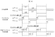
図4は、制御部107から電力変換部104に与える1相分の電圧パルス指令の様子を示している。制御部107は、電力変換部104の制御用の信号として、スイッチング回路の上アームと104aと下アーム104bの短絡防止用に、デッドタイムを付加したPWMの制御信号を出力する。具体的には、過励磁判定部109が過励磁と判断した場合、前記過励磁判定部からの過励磁の判断情報に基いて、制御部107が上記上アームと下アームの短絡防止用に設定されたデッドタイムを最小値とし、デッドタイム指令値を付加してデッドタイムを可変(増加)させる。このように、デッドタイムを増加させるとPWMの制御信号のパルス幅が減少し、電力変換部104から交流電動機105に出力される出力電圧及び、交流電動機105に流れる電流を抑えることが可能となる。
FIG. 4 shows a state of a voltage pulse command for one phase given from the
制御部107がデッドタイムを可変させる場合、例えば最少デッドタイムが3μs、可変範囲を10μsと決めたとすると、交流電動機105が過励磁となった時に、即座にデッドタイムを10μsにしてもよいし、徐々に10μsに近づけてもよい。また、交流電動機105が過励磁状態から復帰した際に、デッドタイムを最小値に戻す過程も同様である。また、デッドタイムを可変させる際に、1次電流あるいは励磁電流が、規定電流値を超えた量に連動して、デッドタイムを広げてもよい。
When the
次に、過励磁状態となった場合に、制御部107が交流電動機105への出力電圧を制御して運転継続させる他の例について説明する。ここでは、電力変換部104の出力電圧を制御するために、制御部107から電力変換部104に励磁電圧指令が供給されるが、この励磁電圧指令を利用している。
Next, another example will be described in which the
交流電動機105が過励磁状態になった場合、制御部107は、前記過励磁判定部からの過励磁の判断情報に基いて、電力変換部104の出力電圧が下がる方向に、励磁電圧指令を補正制御を行い、交流電動機105の運転を継続する。補正制御は、例えば、励磁電流が規定電流値以上になって過励磁となった場合に、規定電流値を目標値として励磁電圧指令を下げる方向(負の方向)にPI制御する。そして、下げる方向に制御した負の積算項が、正(負からゼロを超えて正)になった場合(PI制御で励磁電流が規定電流値まで低下した場合)、励磁電流が過励磁状態から抜け出したと判断する。
When the
また、運転を停止する例としては、過励磁状態になった場合、制御部107の指令が交流電動機105を減速停止させるか、または、電力変換部104の出力を遮断させる制御を行う。これは例えば、制御部107が交流電動機105を制御する際に、制御に用いるパラメータ設定が適切でない等の理由で過励磁となった場合は、パラメータ設定の変更が伴うので、交流電動機105を停止させて過励磁状態の警告を発生させる。標準品でなく想定外の電動機が接続された状態で過励磁が発生した場合に、この制御が必要となる。
Further, as an example of stopping the operation, when an overexcitation state is reached, a command from the
本実施例では実施例1と、共通する部分については同様の符号を用いて説明し、異なる部分について詳細に説明するものとする。本実施例の構成は、実施例1にて説明した図1と同様である。 In the present embodiment, parts common to those in the first embodiment will be described using the same reference numerals, and different parts will be described in detail. The configuration of this embodiment is the same as that of FIG. 1 described in the first embodiment.
電流変換部112は、実施例1と同様に、電流検出部111から入力した3相交流電流から、前記した(式1)で2軸の固定座標系に変換し、それを(式2)で回転座標系に変換する。これにより、電動機の励磁に寄与する励磁電流と、電動機のトルクに寄与するトルク電流を検出することができる。また、変換した励磁電流とトルク電流とから、(式3)により交流電動機105に流れる一次電流を求める。
Similarly to the first embodiment, the
過励磁判定部109は、記憶部108に記憶された設定情報、および電流変換部112が変換して得た電流情報、制御部107が演算した励磁電流指令を入力とし、交流電動機105が過励磁であるかどうかを判定し、その判定情報を表示部106及び制御部107に出力する。その具体的な制御について、図5を用いて説明する。
The overexcitation determination unit 109 receives the setting information stored in the
まず、過励磁判定部109は、電流変換部112で出力した励磁電流値(検出励磁電流)と制御部107で演算された励磁電流指令(励磁電流比較値)を取り込む(S501)。次に、過励磁判定部109は、検出励磁電流と演算された励磁電流比較値とを比較する(S502)。この時の励磁電流比較値は、電動機の標準の励磁電流指令値から計算された値であって、例えば無負荷状態での励磁電流指令値の150%とする。このように、本実施例では、電流変換部112で出力した励磁電流値と、制御部107で演算された励磁電流指令(励磁電流比較値)とを比較して、過励磁を判断している。
First, the overexcitation determination unit 109 takes in the excitation current value (detection excitation current) output from the
このように、本実施例では、励磁電流同士を直接比較しているので、より正確にかつ簡単な構成で、過励磁を判定することができる。 As described above, in this embodiment, since the excitation currents are directly compared, overexcitation can be determined with a more accurate and simple configuration.
過励磁判定部109は、励磁電流値が励磁電流比較値よりも大きければ過励磁状態と判断する(S503)。過励磁判定部109は、判定された過励磁情報を表示部106及び制御部107に出力する(S504)。この時、過励磁判定部109は、一旦過励磁状態となってから、再び正常な状態に戻った場合に、過励磁から正常励磁になり動作が不安定になるので、これを防ぐ目的で、状態の変化に時限特性を持たせてもよい。
If the excitation current value is larger than the excitation current comparison value, the overexcitation determination unit 109 determines that the overexcitation state is present (S503). The overexcitation determination unit 109 outputs the determined overexcitation information to the
過励磁を抑える動作制御の詳しい例を挙げる。過励磁状態となった場合に、制御部107から電力変換部104へのPWMの制御信号を制御することで、電力変換部104から交流電動機105への出力パルスを制御しながら運転を継続させる。実施例1と同様に、図4に示すようにパルス幅を制御することで、電力変換部104から交流電動機105に出力される出力電圧及び、交流電動機105に流れる電流を抑えることが可能となる。
A detailed example of operation control to suppress overexcitation will be given. In the overexcitation state, the PWM control signal from the
また、過励磁状態となった場合に、制御部107が交流電動機105への出力電圧を制御しながら、運転を継続させる他の例についても、実施例1と同様に制御を行うものである。さらに、運転を停止する一例としては、過励磁状態になった場合に、制御部107が、交流電動機105を減速停止させるか、または電力変換部の出力を遮断させる。これは例えば、制御部107が、交流電動機105を制御する際に、制御に用いるパラメータ設定が適切でない等の理由で過励磁となった場合に、パラメータの設定変更に備えて、交流電動機105を停止させて、過励磁状態の警告を発生させる。
In addition, in the case of the overexcitation state, the
なお、本発明は上記した実施例に限定されるものではなく、様々な変形例が含まれる。例えば、上記した実施例は本発明を分かりやすく説明するために詳細に説明したものであり、必ずしも説明した全ての構成を備えるものに限定されるものではない。
また、ある実施例の構成の一部を他の実施例の構成に置き換えることが可能であり、また、ある実施例の構成に他の実施例の構成を加えることも可能である。また、各実施例の構成の一部について、他の構成の追加・削除・置換をすることが可能である。
In addition, this invention is not limited to an above-described Example, Various modifications are included. For example, the above-described embodiments have been described in detail for easy understanding of the present invention, and are not necessarily limited to those having all the configurations described.
Further, a part of the configuration of one embodiment can be replaced with the configuration of another embodiment, and the configuration of another embodiment can be added to the configuration of one embodiment. Further, it is possible to add, delete, and replace other configurations for a part of the configuration of each embodiment.
また、上記の各構成、機能、処理部、処理手段等は、それらの一部又は全部を、例えば集積回路で設計する等によりハードウェアで実現してもよい。また、上記の各構成、機能等は、プロセッサがそれぞれの機能を実現するプログラムを解釈し、実行することによりソフトウェアで実現してもよい。各機能を実現するプログラム、テーブル、ファイル等の情報は、メモリや、ハードディスク、SSD(SOLID STATE DRIVE)等の記録装置、または、ICカード、SDカード、DVD等の記録媒体に置くことができる。 Each of the above-described configurations, functions, processing units, processing means, and the like may be realized by hardware by designing a part or all of them with, for example, an integrated circuit. Each of the above-described configurations, functions, and the like may be realized by software by interpreting and executing a program that realizes each function by the processor. Information such as programs, tables, and files for realizing each function can be stored in a recording device such as a memory, a hard disk, and an SSD (SOLID STATE DRIVE), or a recording medium such as an IC card, an SD card, and a DVD.
また、制御線や情報線は説明上必要と考えられるものを示しており、製品上必ずしも全ての制御線や情報線を示しているとは限らない。実際には殆ど全ての構成が相互に接続されていると考えてもよい。 Further, the control lines and information lines indicate what is considered necessary for the explanation, and not all the control lines and information lines on the product are necessarily shown. Actually, it may be considered that almost all the components are connected to each other.
101…3相交流電圧、102…直流変換部、103…平滑コンデンサ、104…電力変換部、104a…上アーム、104b…下アーム、105…交流電動機、106…表示部、107…制御部、108…記憶部、109…過励磁判定部、110…電流検出器、111…電流検出部、112…電流変換部。
DESCRIPTION OF
Claims (10)
前記電力変換部から交流電動機に出力される電流を検出する電流検出部と、
前記電流検出部で検出された電流情報を励磁電流、トルク電流および一次電流に変換する電流変換部と、
前記電流変換部で変換された励磁電流とトルク電流とを比較し、励磁電流がトルク電流より大きいとき、過励磁の判断情報を出力する過励磁判定部と、
前記過励磁判定部からの過励磁の判断情報と予め設定された設定情報に基いて、電力変換部に制御信号を与えて、電力変換部から交流電動機に供給される出力を制御する制御部を備えたことを特徴とする電力変換装置。 A power converter that converts DC power into desired AC power;
A current detection unit for detecting a current output from the power conversion unit to the AC motor;
A current converter that converts the current information detected by the current detector into an excitation current, a torque current, and a primary current;
Comparing the excitation current converted by the current conversion unit and the torque current, and when the excitation current is larger than the torque current, an overexcitation determination unit that outputs overexcitation determination information;
A control unit that gives a control signal to the power conversion unit based on the determination information of overexcitation from the overexcitation determination unit and preset setting information, and controls the output supplied from the power conversion unit to the AC motor. A power conversion device comprising:
前記電力変換部から交流電動機に出力される電流を検出する電流検出部と、
前記電流検出部で検出された電流を励磁電流に変換する電流変換部と、
励磁電流指令を演算して前記電力変換装置へ供給する制御部と、
前記励磁電流指令と前記励磁電流を比較し、励磁電流が励磁電流指令より大きいとき、過励磁の判断情報を出力する過励磁判定部を備え、
前記制御部は、前記過励磁判定部からの過励磁の判断情報に基いて、電力変換部に制御信号を与えて、電力変換部から交流電動機に供給される出力を制御することを特徴とする電力変換装置。 A power converter that converts DC power into desired AC power;
A current detection unit for detecting a current output from the power conversion unit to the AC motor;
A current converter that converts the current detected by the current detector into an excitation current;
A control unit that calculates an excitation current command and supplies it to the power converter;
The excitation current command and the excitation current are compared, and when the excitation current is larger than the excitation current command, an overexcitation determination unit that outputs overexcitation determination information is provided,
The control unit gives a control signal to the power conversion unit based on overexcitation determination information from the overexcitation determination unit, and controls an output supplied from the power conversion unit to the AC motor. Power conversion device.
Priority Applications (4)
| Application Number | Priority Date | Filing Date | Title |
|---|---|---|---|
| JP2011160384A JP5659330B2 (en) | 2011-07-22 | 2011-07-22 | Power converter |
| EP12817332.5A EP2736165B1 (en) | 2011-07-22 | 2012-05-28 | Power converter |
| PCT/JP2012/063681 WO2013015010A1 (en) | 2011-07-22 | 2012-05-28 | Power converter |
| CN201280035185.9A CN103650334B (en) | 2011-07-22 | 2012-05-28 | Power inverter |
Applications Claiming Priority (1)
| Application Number | Priority Date | Filing Date | Title |
|---|---|---|---|
| JP2011160384A JP5659330B2 (en) | 2011-07-22 | 2011-07-22 | Power converter |
Publications (2)
| Publication Number | Publication Date |
|---|---|
| JP2013027179A JP2013027179A (en) | 2013-02-04 |
| JP5659330B2 true JP5659330B2 (en) | 2015-01-28 |
Family
ID=47600870
Family Applications (1)
| Application Number | Title | Priority Date | Filing Date |
|---|---|---|---|
| JP2011160384A Expired - Fee Related JP5659330B2 (en) | 2011-07-22 | 2011-07-22 | Power converter |
Country Status (4)
| Country | Link |
|---|---|
| EP (1) | EP2736165B1 (en) |
| JP (1) | JP5659330B2 (en) |
| CN (1) | CN103650334B (en) |
| WO (1) | WO2013015010A1 (en) |
Families Citing this family (2)
| Publication number | Priority date | Publication date | Assignee | Title |
|---|---|---|---|---|
| CN107565515B (en) * | 2017-08-17 | 2019-05-21 | 国家电网公司 | A kind of transformer over-excitation protection method using angle compensation voltage magnitude |
| CN111052594B (en) * | 2017-12-07 | 2023-04-18 | 株式会社日立产机系统 | Power conversion device, motor control system, and parameter setting method thereof |
Family Cites Families (11)
| Publication number | Priority date | Publication date | Assignee | Title |
|---|---|---|---|---|
| JP3226253B2 (en) * | 1995-09-11 | 2001-11-05 | 株式会社東芝 | Control device for permanent magnet synchronous motor |
| JPH1118496A (en) * | 1997-06-18 | 1999-01-22 | Hitachi Ltd | Controller and control method for electric vehicle |
| JP2001218500A (en) * | 2000-01-31 | 2001-08-10 | Sumitomo Heavy Ind Ltd | Energy-saving operation method for induction motor |
| JP2002186293A (en) * | 2000-12-12 | 2002-06-28 | Kokusan Denki Co Ltd | Control device of dynamo-electric machine for internal combustion engine |
| JP3918148B2 (en) * | 2001-07-24 | 2007-05-23 | 株式会社日立製作所 | Inverter device |
| KR100442494B1 (en) * | 2002-02-26 | 2004-07-30 | 엘지산전 주식회사 | Control method and controller for torque of inverter |
| JP4223880B2 (en) * | 2003-07-31 | 2009-02-12 | トヨタ自動車株式会社 | Motor drive device |
| JP4455075B2 (en) * | 2004-01-28 | 2010-04-21 | 三菱電機株式会社 | Motor control device |
| JP2008172949A (en) * | 2007-01-12 | 2008-07-24 | Yaskawa Electric Corp | Power conversion device and motor protection method therefor |
| EP2192684B1 (en) * | 2007-09-18 | 2020-07-08 | Kabushiki Kaisha Toshiba | Variable magnetic flux drive system |
| DE102009021823A1 (en) * | 2009-05-18 | 2010-12-09 | Bombardier Transportation Gmbh | Overcurrent limiting in the control of converter-fed three-phase machines |
-
2011
- 2011-07-22 JP JP2011160384A patent/JP5659330B2/en not_active Expired - Fee Related
-
2012
- 2012-05-28 CN CN201280035185.9A patent/CN103650334B/en active Active
- 2012-05-28 WO PCT/JP2012/063681 patent/WO2013015010A1/en active Application Filing
- 2012-05-28 EP EP12817332.5A patent/EP2736165B1/en active Active
Also Published As
| Publication number | Publication date |
|---|---|
| EP2736165A4 (en) | 2015-10-28 |
| CN103650334A (en) | 2014-03-19 |
| JP2013027179A (en) | 2013-02-04 |
| EP2736165B1 (en) | 2020-04-08 |
| WO2013015010A1 (en) | 2013-01-31 |
| EP2736165A1 (en) | 2014-05-28 |
| CN103650334B (en) | 2016-06-22 |
Similar Documents
| Publication | Publication Date | Title |
|---|---|---|
| JP5274236B2 (en) | Three-phase inverter power circuit protection device | |
| JP5628994B2 (en) | Machine tool control device having time estimation means for estimating time until motor reaches overheat temperature | |
| CN111245323B (en) | Motor control method and device, computer readable storage medium and electrical equipment | |
| JP6277288B2 (en) | Monitoring device and monitoring method, and control device and control method including the same | |
| JP5906679B2 (en) | Power converter and overcurrent protection circuit | |
| JP2006054991A (en) | Sensorless motor driver and its protective control method | |
| JP5880420B2 (en) | Inverter device | |
| JP2011155803A (en) | Motor driving apparatus having power failure detection function | |
| JP2009207307A (en) | Motor driving apparatus | |
| JP5476788B2 (en) | Inverter device | |
| JP5659330B2 (en) | Power converter | |
| JP6286450B2 (en) | Power converter | |
| JP6282338B2 (en) | Power conversion device and power conversion method | |
| JP6915695B2 (en) | Motor control method and motor control device | |
| JP6353925B2 (en) | Power converter and control method of power converter | |
| KR20150078661A (en) | Apparatus and Method for sensing demagnetization of motor | |
| EP3016257A1 (en) | Apparatus and method for controlling overcurrent of grid-connected inverter due to abnormal grid voltage | |
| JP2015126648A (en) | Power conversion device and control method for power conversion device | |
| JP2014143839A (en) | Control device for motor | |
| US11177757B2 (en) | Power conversion device | |
| KR102523153B1 (en) | Motor drive apparatus performing algorithm for preventing abnormal operation | |
| JP2006271159A (en) | Dielectric breakdown detector for electric motor winding | |
| EP3016258B1 (en) | Apparatus and method for protecting grid-connected inverter from occurrence of low grid voltage | |
| JP5844665B2 (en) | Power conversion apparatus and control method | |
| JP2016146693A (en) | Overload protecting device |
Legal Events
| Date | Code | Title | Description |
|---|---|---|---|
| A621 | Written request for application examination |
Free format text: JAPANESE INTERMEDIATE CODE: A621 Effective date: 20140117 |
|
| TRDD | Decision of grant or rejection written | ||
| A01 | Written decision to grant a patent or to grant a registration (utility model) |
Free format text: JAPANESE INTERMEDIATE CODE: A01 Effective date: 20140902 |
|
| RD02 | Notification of acceptance of power of attorney |
Free format text: JAPANESE INTERMEDIATE CODE: A7422 Effective date: 20140930 |
|
| A61 | First payment of annual fees (during grant procedure) |
Free format text: JAPANESE INTERMEDIATE CODE: A61 Effective date: 20140930 |
|
| R150 | Certificate of patent or registration of utility model |
Ref document number: 5659330 Country of ref document: JP Free format text: JAPANESE INTERMEDIATE CODE: R150 |
|
| LAPS | Cancellation because of no payment of annual fees |