JP5598200B2 - Data processing apparatus, data processing method, and program - Google Patents
Data processing apparatus, data processing method, and program Download PDFInfo
- Publication number
- JP5598200B2 JP5598200B2 JP2010208231A JP2010208231A JP5598200B2 JP 5598200 B2 JP5598200 B2 JP 5598200B2 JP 2010208231 A JP2010208231 A JP 2010208231A JP 2010208231 A JP2010208231 A JP 2010208231A JP 5598200 B2 JP5598200 B2 JP 5598200B2
- Authority
- JP
- Japan
- Prior art keywords
- parameter
- model
- data
- probability
- state
- Prior art date
- Legal status (The legal status is an assumption and is not a legal conclusion. Google has not performed a legal analysis and makes no representation as to the accuracy of the status listed.)
- Expired - Fee Related
Links
Images


Classifications
-
- G—PHYSICS
- G06—COMPUTING; CALCULATING OR COUNTING
- G06F—ELECTRIC DIGITAL DATA PROCESSING
- G06F17/00—Digital computing or data processing equipment or methods, specially adapted for specific functions
- G06F17/10—Complex mathematical operations
- G06F17/18—Complex mathematical operations for evaluating statistical data, e.g. average values, frequency distributions, probability functions, regression analysis
-
- G—PHYSICS
- G01—MEASURING; TESTING
- G01R—MEASURING ELECTRIC VARIABLES; MEASURING MAGNETIC VARIABLES
- G01R22/00—Arrangements for measuring time integral of electric power or current, e.g. electricity meters
- G01R22/06—Arrangements for measuring time integral of electric power or current, e.g. electricity meters by electronic methods
- G01R22/10—Arrangements for measuring time integral of electric power or current, e.g. electricity meters by electronic methods using digital techniques
-
- G—PHYSICS
- G01—MEASURING; TESTING
- G01R—MEASURING ELECTRIC VARIABLES; MEASURING MAGNETIC VARIABLES
- G01R19/00—Arrangements for measuring currents or voltages or for indicating presence or sign thereof
- G01R19/25—Arrangements for measuring currents or voltages or for indicating presence or sign thereof using digital measurement techniques
- G01R19/2516—Modular arrangements for computer based systems; using personal computers (PC's), e.g. "virtual instruments"
-
- G—PHYSICS
- G01—MEASURING; TESTING
- G01R—MEASURING ELECTRIC VARIABLES; MEASURING MAGNETIC VARIABLES
- G01R21/00—Arrangements for measuring electric power or power factor
- G01R21/001—Measuring real or reactive component; Measuring apparent energy
-
- G—PHYSICS
- G06—COMPUTING; CALCULATING OR COUNTING
- G06N—COMPUTING ARRANGEMENTS BASED ON SPECIFIC COMPUTATIONAL MODELS
- G06N7/00—Computing arrangements based on specific mathematical models
- G06N7/01—Probabilistic graphical models, e.g. probabilistic networks
-
- G—PHYSICS
- G01—MEASURING; TESTING
- G01R—MEASURING ELECTRIC VARIABLES; MEASURING MAGNETIC VARIABLES
- G01R19/00—Arrangements for measuring currents or voltages or for indicating presence or sign thereof
- G01R19/25—Arrangements for measuring currents or voltages or for indicating presence or sign thereof using digital measurement techniques
- G01R19/2506—Arrangements for conditioning or analysing measured signals, e.g. for indicating peak values ; Details concerning sampling, digitizing or waveform capturing
Description
本発明は、データ処理装置、データ処理方法、およびプログラムに関し、特に、取得される電流情報から電気機器を推定する場合において、パラメータの算出及び調整が簡単であり、かつ、事前のデータベースが不要な手法を確立することができるようにするデータ処理装置、データ処理方法、およびプログラムに関する。 The present invention relates to a data processing device, a data processing method, and a program, and in particular, when estimating an electrical device from acquired current information, parameter calculation and adjustment are simple, and no prior database is required. The present invention relates to a data processing apparatus, a data processing method, and a program that enable a technique to be established.
分電盤で計測した電流の情報から、その先につながっている電気機器を推定する技術は、 Non-intrusive load monitoring (以下、NILMという。)と呼ばれ、1980年代から研究されている。NILMは、個々の電気機器(負荷)それぞれに測定機器を必要とせず、一箇所の計測結果だけに基づいて、そこから先につながっている電気機器全ての状態を把握できることが大きな利点となっている。 A technique for estimating the electrical equipment connected to the current from information measured by the distribution board is called non-intrusive load monitoring (NILM) and has been studied since the 1980s. NILM does not require a measurement device for each individual electrical device (load), and it is a great advantage that it can grasp the status of all electrical devices connected to it based on the measurement results at one location. Yes.
NILMの代表的なものとして、例えば、特許文献1には、電流と電圧の計測から、有効電力(real power)及び無効電力(reactive power)を算出し、その変化量をクラスタリングすることで、電気機器の同定を行う技術が開示されている。変化量を取るのは、電気機器のオン、オフ時に、計測される有効電力及び無効電力が変化するからである。
As a typical NILM, for example,
図1は、特許文献1において図8として示されている図である。図1では、有効電力及び無効電力を軸とする2次元平面に、冷蔵庫(Refrigerator)と暖房(Heater)のオン、オフ時の有効電力と無効電力がプロットされている。図1によれば、電気機器のオンとオフが点対称の位置にプロットされていることがわかる。 FIG. 1 is a diagram shown in FIG. In FIG. 1, active power and reactive power when a refrigerator and a heater are turned on and off are plotted on a two-dimensional plane with active power and reactive power as axes. According to FIG. 1, it can be seen that the on / off state of the electrical device is plotted at point-symmetric positions.
特許文献1の方法は、オン、オフ時の差分を取るので、変化した瞬間の情報しか利用していない。また、変化点の検出器(Change detector)が必要となるが、この変化点検出器が失敗する(オン若しくはオフを取り逃す、または、過剰に変化を誤検出する)と、後段の処理全体が失敗してしまう。
Since the method of
即ち、特許文献1の方法には、次のような問題がある。第1に、オン、オフ時の差分を取るので、変化した瞬間の情報しか利用していない。第2に、変化点検出のしきい値調整が難しく、変化点検出器(net change detection)が失敗すると後段の処理が全て失敗してしまう。第3に、80年代の当時の家電はシンプルな負荷であるものが多かったため適用できたが、現代の電気機器ではオン、オフだけに分類できず、うまく機能しないものが多い。
That is, the method of
近年の複雑な電力消費を行う電気機器に対応するため、NILMの側も何らかの複雑な処理を行う必要が出てきている。その試みとして、識別モデル(判別モデル、Classification)を用いる方法が多く提案されている。識別モデルにSupport Vector MachineなどのLMC(Large Margin Classifier)を利用した方法として、例えば、特許文献2及び3に開示された方法がある。
In order to cope with the electrical equipment that consumes complex power in recent years, the NILM needs to perform some complicated processing. As a trial, many methods using an identification model (discriminant model, Classification) have been proposed. As a method using LMC (Large Margin Classifier) such as Support Vector Machine for the identification model, there are methods disclosed in
AdaBoostやSupport Vector Machineなどの識別モデルは、特徴量をうまく選択し、かつ学習用のサンプルデータが十分に多い場合は、非常に高い識別性能を示すことが知られているため、この手法は精度向上には有効であるとも思われる。しかし、一方で、識別モデルはHMMなどの生成モデルとは違い、事前に学習データを用意して学習を済ませておく必要があり、更にその学習結果をデータベースとして保持しておく必要がある。つまり、未知の電気機器に対応することはできないという欠点がある。 Identification methods such as AdaBoost and Support Vector Machine are known to exhibit very high discrimination performance when feature quantities are selected well and there are enough sample data for learning. It seems to be effective for improvement. However, on the other hand, an identification model is different from a generation model such as an HMM, and it is necessary to prepare learning data in advance and complete learning, and to store the learning result as a database. In other words, there is a drawback that it is not possible to deal with unknown electrical devices.
特許文献4及び非特許文献1のように、単純な線形モデルで判別を行うものもあるが、事前のデータベースが必要であるという点では、特許文献2及び3に開示された技術と同じ問題を抱えている。事前に用意したデータベースを用いる手法は、その他、特許文献5や6として提案されているものがある。
Although there are some which perform discrimination by a simple linear model as in
結局のところ、上述した従来の手法は、精度を取るか、または、事前登録が不要な手法を取るか、のトレードオフになっている。近年、家庭の電気機器は非常に多様化しており、事前学習が必要である識別モデルでは、事実上、家庭での使用に耐えられないと考えられるため、やはり、事前登録不要な手法の方が望ましい。 After all, the conventional method described above is a trade-off between accuracy and a method that does not require pre-registration. In recent years, household electrical appliances have become very diverse, and identification models that require prior learning are virtually incapable of being used at home. desirable.
そこで、事前学習が必要な識別モデルではなく、生成モデルを使う試みも既に行われている。例えば、生成モデルとしてHidden Markovモデル(HMM)を適用したものが提案されている(例えば、非特許文献2,3参照)。
Therefore, an attempt has already been made to use a generation model instead of an identification model that requires prior learning. For example, a model in which a Hidden Markov model (HMM) is applied as a generation model has been proposed (see, for example, Non-Patent
しかし、生成モデルとして単純なHMMを適用した場合には、電気機器の数が増えると状態数が爆発し(膨大となり)、現実的なシステムを構築することができないという問題がある。例えば、個々の電気機器が、仮にオンとオフの2状態をもち、電気機器の数をnとしたとき、必要な状態数は、2nである。更に、状態遷移確率のサイズはその二乗(2n)2となる。一般家庭の全ての電気機器が仮に20個あったとして(近年では決して多いとは言えない)、必要な状態数は220=1,048,576 であり、状態遷移確率は1,099,511,627,776 の大きさとなる。これはテラオーダーのサイズであり、近年のパーソナルコンピュータでも取り扱うのは困難である。 However, when a simple HMM is applied as a generation model, there is a problem that when the number of electrical devices increases, the number of states explodes (becomes huge) and a realistic system cannot be constructed. For example, if each electric device has two states of on and off, and the number of electric devices is n, the required number of states is 2 n . Further, the size of the state transition probability is its square (2 n ) 2 . Assuming that there are 20 electric appliances in a general household (which cannot be said to be many in recent years), the required number of states is 2 20 = 1,048,576, and the state transition probability is 1,099,511,627,776. This is a tera-order size and is difficult to handle even in recent personal computers.
ちなみに、特許文献1の方法も、クラスタリングをベースとしており、原始的な生成モデルと考えることができるため、事前登録は不要である。特許文献1の方法のような、確率モデルによるアプローチが一般化する以前の時代の、モデル化をせずに問題を解く方法は、ヒューリスティックな方法と呼ばれる。ヒューリスティックな方法は、ファーストステップとしては良いが、方法を拡張していくうちに閾値などのパラメータがどんどん増えていき、それらの調整が困難になるという問題を抱えている。
Incidentally, since the method of
近年、コンピュータを利用した自動認識技術は、確率モデルの導入により様々な難しい問題が解決できるようになってきている。確率モデルによりうまくモデル化できれば、ほとんどのパラメータが最尤推定(ML推定、Maximum Likelihood)や事後確率最大化(MAP推定、Maximum A Posteriori)、最小識別誤差(MCE、Minimum Classification Error)などにより求めることが可能である。Support Vector Machineのような識別モデルや、HMMのような生成モデルを利用することが、確率モデルによるモデル化に相当する。 In recent years, automatic recognition technology using a computer has been able to solve various difficult problems by introducing a probability model. If the model can be well modeled by the probabilistic model, most parameters should be obtained by maximum likelihood estimation (ML estimation, Maximum Likelihood), posterior probability maximization (MAP estimation, Maximum A Posteriori), minimum classification error (MCE, Minimum Classification Error), etc. Is possible. Using an identification model such as Support Vector Machine and a generation model such as HMM corresponds to modeling by a probabilistic model.
以上のことから、次の3点を解決するNILMの手法が望まれる。第1に、ヒューリスティックな方法が抱えるようなパラメータ調整が困難であるという問題を解決すること、即ち、パラメータ調整が簡単であることが望まれる。第2に、識別モデルのように事前のデータベースが必要であると、近年益々増大する新しい電気機器に対応することが困難になることから、事前のデータベースが不要であることが望まれる。第3に、状態数が爆発してしまうパラメータ推定アルゴリズムでは実質的に解くことができないので、状態数がパラメータ算出可能な現実的な個数であることが必要である。 In view of the above, a NILM method that solves the following three points is desired. First, it is desired to solve the problem that the parameter adjustment that the heuristic method has is difficult, that is, the parameter adjustment is simple. Secondly, if a prior database such as an identification model is required, it becomes difficult to cope with new electrical equipment that has been increasing in recent years. Therefore, it is desirable that the prior database is unnecessary. Third, since the parameter estimation algorithm that explodes the number of states cannot be solved practically, the number of states needs to be a realistic number that can be calculated.
本発明は、このような状況に鑑みてなされたものであり、取得される電流情報から電気機器を推定する場合において、パラメータの算出及び調整が簡単であり、かつ、事前のデータベースが不要な手法を確立することができるようにするものである。 The present invention has been made in view of such a situation, and in the case of estimating an electrical device from acquired current information, a method for easily calculating and adjusting parameters and does not require a prior database. To be able to establish.
本発明の一側面のデータ処理装置は、複数の波形の合計値の時系列データを取得し、取得した前記時系列データを、非負のデータに変換するデータ取得手段と、非負のデータに変換された前記時系列データに基づいて、前記複数の波形それぞれが示す状態を確率モデルによりモデル化したときのモデルパラメータを求めるパラメータ推定手段とを備え、前記パラメータ推定手段は、EMアルゴリズムによるパラメータ推定処理において、前記確率モデルのファクタm(m=1乃至Mの正の整数)の波形のパターンに対応する観測確率のパラメータW (m) が非負であるという制約条件の下で、前記確率モデルが、前記時系列データが表す前記波形の合計値のパターンを説明する度合いである尤度関数を最大化することにより、前記モデルパラメータとしての観測確率のパラメータW (m) を求める。 One aspect data processing apparatus of the present invention obtains the time-series data of the sum of a plurality of waveforms, the obtained the time-series data, a data acquisition means for converting the non-negative data are converted into a non-negative data were based on the time-series data, a parameter estimation means for determining model parameters when the state of each of the plurality of waveforms illustrating modeled by probabilistic model, the parameter estimation unit, in the parameter estimation process by the EM algorithm Under the constraint that the observation probability parameter W (m) corresponding to the waveform pattern of the factor m (m = 1 to M positive integer) of the probability model is non-negative, the probability model By maximizing a likelihood function, which is a degree that explains the pattern of the total value of the waveform represented by time series data, Determine the parameters W of the observation probability (m).
本発明の一側面のデータ処理方法は、データ処理装置が、複数の波形の合計値の時系列データを取得し、取得した前記時系列データを、非負のデータに変換し、非負のデータに変換された前記時系列データに基づいて、前記複数の波形それぞれが示す状態を確率モデルによりモデル化したときのモデルパラメータを求め、EMアルゴリズムによるパラメータ推定処理では、前記確率モデルのファクタm(m=1乃至Mの正の整数)の波形のパターンに対応する観測確率のパラメータW (m) が非負であるという制約条件の下で、前記確率モデルが、前記時系列データが表す前記波形の合計値のパターンを説明する度合いである尤度関数を最大化することにより、前記モデルパラメータとしての観測確率のパラメータW (m) を求めるステップを含む。 In the data processing method according to one aspect of the present invention, a data processing device acquires time-series data of a total value of a plurality of waveforms , converts the acquired time-series data into non-negative data, and converts it into non-negative data based on the time-series data, the calculated model parameters when modeled by a plurality of waveform probabilistic model, the state shown respectively, in the parameter estimation process by EM algorithm, factor m of the probabilistic model (m = 1 To a positive integer of M), under the constraint that the observation probability parameter W (m) corresponding to the waveform pattern is non-negative, the probability model has a total value of the waveform represented by the time-series data. Maximizing a likelihood function, which is a degree explaining the pattern, to obtain an observation probability parameter W (m) as the model parameter .
本発明の一側面のプログラムは、コンピュータを、複数の波形の合計値の時系列データを取得し、取得した前記時系列データを、非負のデータに変換するデータ取得手段と、非負のデータに変換された前記時系列データに基づいて、前記複数の波形それぞれが示す状態を確率モデルによりモデル化したときのモデルパラメータを求めるパラメータ推定手段として機能させ、前記パラメータ推定手段は、EMアルゴリズムによるパラメータ推定処理において、前記確率モデルのファクタm(m=1乃至Mの正の整数)の波形のパターンに対応する観測確率のパラメータW (m) が非負であるという制約条件の下で、前記確率モデルが、前記時系列データが表す前記波形の合計値のパターンを説明する度合いである尤度関数を最大化することにより、前記モデルパラメータとしての観測確率のパラメータW (m) を求めるものである。 One aspect of the program of the present invention, converts the computer, acquires the time series data of the sum of a plurality of waveforms, the said time-series data acquisition, and data acquisition means for converting the non-negative data, the non-negative data based on the time-series data, each of the plurality of waveforms to function as a parameter estimation means for determining the model parameters when modeled by probabilistic model state indicated by the said parameter estimation means, parameter estimation process by the EM algorithm The probability model W (m) corresponding to the waveform pattern of the factor m (m = 1 to M positive integer) of the probability model is non-negative, the probability model is By maximizing a likelihood function, which is a degree that explains the pattern of the total value of the waveform represented by the time series data, the model And requests the parameter W (m) of the observation probability of the Le parameters.
本発明の一側面においては、複数の波形の合計値の時系列データが取得され、取得された時系列データが、非負のデータに変換され、非負のデータに変換された時系列データに基づいて、複数の波形それぞれが示す状態を確率モデルによりモデル化したときのモデルパラメータが求められる。EMアルゴリズムによるパラメータ推定処理では、確率モデルのファクタm(m=1乃至Mの正の整数)の波形のパターンに対応する観測確率のパラメータW (m) が非負であるという制約条件の下で、確率モデルが、時系列データが表す波形の合計値のパターンを説明する度合いである尤度関数を最大化することにより、モデルパラメータとしての観測確率のパラメータW (m) が求められる。 In one aspect of the present invention, time-series data of a total value of a plurality of waveforms is acquired, and the acquired time-series data is converted into non-negative data , based on the time-series data converted into non-negative data. , the model parameters when modeled by probabilistic model state shown each of the plurality of waveforms is required. In the parameter estimation processing by the EM algorithm , under the constraint that the parameter W (m) of the observation probability corresponding to the waveform pattern of the factor m (m = 1 to M positive integer) of the probability model is non-negative, By maximizing the likelihood function, which is the degree by which the probability model explains the pattern of the total value of the waveform represented by the time series data, the observation probability parameter W (m) as a model parameter is obtained.
本発明の一側面によれば、取得される電流情報から電気機器を推定する場合において、パラメータの算出及び調整が簡単であり、かつ、事前のデータベースが不要な手法を確立することができる。 According to one aspect of the present invention, when estimating an electrical device from acquired current information, it is possible to establish a technique that allows easy calculation and adjustment of parameters and does not require a prior database.
[本発明の概要]
初めに、図2を参照して、本発明を適用したデータ処理装置としての電気機器推定装置の概要について説明する。
[Outline of the present invention]
First, with reference to FIG. 2, an outline of an electrical equipment estimation apparatus as a data processing apparatus to which the present invention is applied will be described.
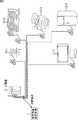
住宅等においては、電力会社から供給される電気は、まず分電盤11に引き込まれ、分電盤11から、住宅内の各場所に設置された電気機器12に供給される。例えば、図2の例では、分電盤11から、電気機器12としての、照明装置(電球)12−1、エアコンディショナ12−2、洗濯機12−3、冷蔵庫12−4、及びテレビジョン受像機12−5に供給されている。
In a house or the like, electricity supplied from an electric power company is first drawn into the
本発明を適用した電気機器推定装置1は、分電盤11の大元の2次側において、住宅内の各場所に設置された複数の電気機器12の使用状態の組み合わせでなる消費電流の合計値を測定することで、複数の電気機器12の稼働状態を推定する。電気機器推定装置1は、推定結果に基づいて、各電気機器12の現在の稼働状態を表示したり、現在より所定時間経過後の未来の電気機器12の稼働状態を予測する。
The electrical
[Factorial HMMについて]
電気機器推定装置1は、NILM の解析手段としてFactorial HMM(Hidden Markov Model)を用いて、各電気機器12の稼働状態を推定する。換言すれば、電気機器推定装置1は、各電気機器12の稼働状態を、Factorial HMMによりモデル化したモデルパラメータを求める。
[About Factorial HMM]
The electrical
そこで、初めに、Factorial HMMについて簡単に説明する。図3は、通常のHMMとFactorial HMMをグラフィカルモデルで表現した図である。 First, a brief description of Factorial HMM will be given. FIG. 3 is a diagram representing a normal HMM and a Factorial HMM in a graphical model.
図3Aが、通常のHMMを表現したグラフィカルモデルであり、図3BがFactorial HMMを表現したグラフィカルモデルである。 FIG. 3A is a graphical model representing a normal HMM, and FIG. 3B is a graphical model representing a Factorial HMM.
通常のHMMでは、時刻tの観測データYtに対して、1つの状態変数Stが対応する。この通常のHMMとFactorial HMMが異なる点は、状態変数StがSt (1),St (2),St (3),・・・St (m),・・・St (M)と、複数(図3ではM個)存在し、それらの複数の状態変数St (1)乃至St (M)から、1つの観測データYtが生成されることである。 In a normal HMM, one state variable St corresponds to the observation data Y t at time t. This conventional HMM and Factorial HMM are different, the state variable S t is S t (1), S t (2), S t (3), ··· S t (m), ··· S t ( M) and a plurality (M in FIG. 3) exist, and one observation data Y t is generated from the plurality of state variables S t (1) to S t (M) .
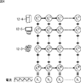
図4は、図3BのFactorial HMMを、図2に示した各電気機器12と対応させて示した図である。
FIG. 4 is a diagram showing the Factorial HMM of FIG. 3B in association with each
Factorial HMMのM個の状態変数S(1) 乃至S(M)のそれぞれが各電気機器12に対応する。また、状態変数S (m)の状態値は、電気機器12の状態(例えば、オン、オフの2状態)に対応する。
Each of the M state variables S (1) to S (M) of the Factorial HMM corresponds to each
より具体的には、M個の状態変数S(1) 乃至S(M)のうち、1番目の状態変数S(1)の時間経過に応じた状態値S1 (1)乃至St (1)が、所定の電気機器12(例えば、冷蔵庫12−4)の状態に対応する。また、2番目の状態変数S(2)の時間経過に応じた状態値S1 (2)乃至St (2)が所定の電気機器12(例えば、テレビジョン受像機12−5)の状態に対応する。同様に、m番目の状態変数S(m)の時間経過に応じた状態値S1 (m)乃至St (m)が所定の電気機器12(例えば、洗濯機12−3)の状態に対応する。 More specifically, among the M state variable S (1) to S (M), the state value corresponding to the time the first state variable S (1) S 1 (1 ) to S t (1 ) Corresponds to the state of the predetermined electrical device 12 (for example, the refrigerator 12-4). Further, the state of the state values corresponding to the time of the second state variable S (2) S 1 (2) to S t (2) is a predetermined electric appliance 12 (for example, a television receiver 12-5) Correspond. Similarly, corresponding to the state of the m-th state variable S state value corresponding to the time (m) S 1 (m) to S t (m) is predetermined electric appliance 12 (e.g., a washing machine 12-3) To do.
また、住宅内の各場所に設置された複数の電気機器12の使用状態の組み合わせでなる消費電流の合計値が、観測データY1乃至Ytとして得られる。
The total value of the consumption current becomes a combination of a plurality of use conditions of the
なお、以下では、M個の状態変数S(1) 乃至S(M)のうちの、m番目の状態変数S(m)を、m番目のファクタ、または、ファクタmとも記述する。 Hereinafter, of the M state variables S (1) to S (M) , the m-th state variable S (m) is also described as the m-th factor or factor m.
Factorial HMMの詳細は、Zoubin Ghahramani, and Michael I. Jordan, Factorial Hidden Markov Models’, Machine Learning Volume 29, Issue 2-3 ,Nov./Dec. 1997(以下、文献Xという。)に、記載されている。 The details of Factorial HMM are described in Zoubin Ghahramani, and Michael I. Jordan, Factorial Hidden Markov Models', Machine Learning Volume 29, Issue 2-3, Nov./Dec. 1997 (hereinafter referred to as Document X). Yes.
[電気機器推定装置1の構成例]
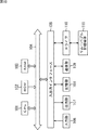
図5は、電気機器推定装置1の構成例を示すブロック図である。
[Configuration Example of Electric Device Estimating Apparatus 1]
FIG. 5 is a block diagram illustrating a configuration example of the electrical
電気機器推定装置1は、センサ部21、パラメータ推定部22、データベース23、同一機器判定部24、状態予測部25、機器特定部26、及び表示部27により構成される。
The electrical
センサ部21は、観測データYt(t=1,2,・・・,T)としての、住宅内の各場所に設置された複数の電気機器12の使用状態の組み合わせでなる消費電流の合計値を測定(取得)し、パラメータ推定部22に供給する。
The
パラメータ推定部22は、複数の電気機器12の消費電流の合計値の時系列データである観測データ{Y1,Y2,Y3,・・・Yt,・・YT}に基づいて、各電気機器12の稼働状態をFactorial HMMによりモデル化したモデルパラメータを求める。Factorial HMMの学習処理により得られたモデルパラメータは、データベース23に保存される。
The
また、パラメータ推定部22は、センサ部21から新たな観測データYtが供給された場合、モデルパラメータをデータベース23から取得し、更新する。即ち、新たな観測データYtに基づいて、現在のモデルパラメータが更新される。
In addition, when new observation data Y t is supplied from the
同一機器判定部24は、M個のファクタのうち、同一の電気機器12をモデル化した複数のファクタを検出し、検出結果をデータベース23に記憶させる。換言すれば、同一機器判定部24は、M個のファクタのうち、第1のファクタm1と第2のファクタm2(m1≠m2)が同一の電気機器12を表現したものであるかを判定し、判定結果をデータベース23に登録する。
The same
Factorial HMM自体は、汎用の時系列データのモデル化手法であり、NILM以外の様々な問題に適用可能なものであるため、従来のFactorial HMMを用いた推定手法そのままでは、NILMにうまく適用できない。その問題の1つが、1つの電気機器12が複数のファクタでモデル化される場合があることである。そこで、同一機器判定部24は、1つの電気機器12が複数のファクタで表現されている場合、その複数のファクタが同一の電気機器12に対応するものであることを検出する。
The Factorial HMM itself is a general-purpose time-series data modeling method and can be applied to various problems other than NILM. Therefore, the estimation method using the conventional Factorial HMM cannot be applied to the NILM. One problem is that one
状態予測部25は、データベース23に記憶されているモデルパラメータを用いて、現在時刻から所定時間経過後の未来のファクタm(の電気機器12)の状態を予測する。Factorial HMMは、言うまでもなくHMMをベースとした確率モデルであるため、未来の時刻の状態確率を確率的に予測することができる。状態予測部25は、現在時刻から所定時間経過後の未来のファクタmの状態の予測結果を、例えば、図示せぬ関連機器制御部等に出力する。これにより、関連機器制御部は、未来のファクタm(の電気機器12)の状態の予測結果に基づいて、ファクタmの電気機器12に関連する他の電気機器12を制御することができる。
The
機器特定部26は、ファクタmがどの電気機器12に対応するのかを特定する。即ち、状態予測部25までの処理では、各ファクタmの状態変化の認識及び予測を行うことはできるが、各ファクタmが住宅内の各場所に設置されたどの電気機器12に対応するかは特定できない。機器特定部26は、各ファクタと住宅内の電気機器12とを対応付ける。例えば、機器特定部26は、電気機器12の製品の種類ごと(洗濯機、冷蔵庫、エアコン、など)に代表的な電流波形パターンを記憶し、その代表的な電流波形パターンと、実際に取得されたファクタの観測データYとを比較して、電気機器12(の種類)を特定する。また例えば、機器特定部26は、不図示の操作部において、各ファクタに対するユーザによる電気機器12の種類の入力操作を受け付け、入力された電気機器12の種類(製品)とファクタの観測データYとを対応付ける。
The
表示部27は、液晶ディスプレイ等により構成され、パラメータ推定部22による推定結果に基づいて、機器特定部26により特定された電気機器12の稼働状況を表示する。
The
以下、電気機器推定装置1を構成する各部の詳細について説明する。
Hereinafter, the detail of each part which comprises the electric
[センサ部21の詳細構成例]
図6は、センサ部21の詳細構成例を示すブロック図である。
[Detailed Configuration Example of Sensor Unit 21]
FIG. 6 is a block diagram illustrating a detailed configuration example of the
センサ部21は、住宅内の各場所に設置された複数の電気機器12の電流及び電圧の合計値を測定する電流測定部41及び電圧測定部42、電流波形切り出し部43、並びに、時系列保持部44により構成される。
The
図7は、単相三線式の配線により複数の電気機器12に電気が供給される場合の、電流測定部41と電圧測定部42の例である。
FIG. 7 is an example of the current measurement unit 41 and the voltage measurement unit 42 when electricity is supplied to the plurality of
電流測定部41は、例えば、2つのクランプ型電流計54及び55により構成され、分電盤11内の大元のアンペアブレーカの2次側に接続された2つの電圧線(ケーブル)51及び53にクランプされ、そこに流れる電流を計測する。
The current measuring unit 41 includes, for example, two clamp-type ammeters 54 and 55, and two voltage lines (cables) 51 and 53 connected to the secondary side of the main amper breaker in the
電圧測定部42は、電圧計56により構成され、所定の電線間の電圧を測定する。電圧は、電流の位相を電圧の位相に同期させるために測定される。従って、電圧測定部42は、電圧線51と中性線52間の電圧、または、中性線52と電圧線53間の電圧のいずれか一方を計測すればよい。図7の例では、電圧計56が電圧線51と中性線52間の電圧を測定している。
The voltage measuring unit 42 includes a
図6に戻り、電流波形切り出し部43は、時々刻々と得られる電流値の時系列データ(電流波形)を時間方向に間引いて代表サンプルを生成し、時刻tの観測データYtとして時系列保持部44に供給する。
Returning to FIG. 6, the current
図8は、電流測定部41により測定された電流値の時系列データの例を示している。 FIG. 8 shows an example of time-series data of current values measured by the current measuring unit 41.
図8上段の波形は、所定の期間内に、電流測定部41により測定された電流値の時系列データであり、振幅の大きさが消費電流の大きさを表す。 The upper waveform in FIG. 8 is time-series data of current values measured by the current measuring unit 41 within a predetermined period, and the magnitude of the amplitude represents the magnitude of current consumption.
図8中段の波形は、図8上段に示した時系列データのうち、4周期分の時系列データを拡大して示したものであり、さらに、図8下段の波形は、中段の4周期分の時系列データのうちの1周期分を拡大して示したものである。 The waveform in the middle of FIG. 8 is an enlarged view of the time-series data for four cycles of the time-series data shown in the upper portion of FIG. 8, and the waveform in the lower portion of FIG. This is an enlarged view of one period of the time series data.
電流波形切り出し部43は、最初に、電流波形の位相を、電圧の位相に同期させる。具体的には、電流波形切り出し部43は、電圧値のゼロ交差の瞬間を、電流波形の位相0として扱う。次に、電流波形切り出し部43は、所定の時間間隔で、1周期分の電流波形をサンプリングする。全ての周期をサンプリングするとデータ量が膨大となってしまうからである。例えば、1秒間に1周期の電流波形を1サンプルとして取得するようにした場合、商用電源周波数50Hzの地域においては、1/50にデータ量を削減することができる。
First, the current
商用電源周波数50Hzの地域において、1回のサンプリングを50kHzでサンプリングすることとすると、図8下段に示されるように、1回のサンプリングで1000個の電流値が得られる。電流波形切り出し部43は、1回のサンプリングで得られた1000個の電流値を1000次元の電流値ベクトルで表し、現在の時刻tにおける観測データYtとして、時系列保持部44に供給する。従って、観測データYtは、D次元(D=1000)の実数ベクトルとなる。
In areas of the utility frequency 50 Hz, the one-time sampling and sampling at 50 k Hz, as shown in the
図6に戻り、時系列保持部44は、電流波形切り出し部43から順次供給される観測データYtを記憶し、保持する。これにより、時系列保持部44には、1サンプルが1000次元の電流値ベクトルで表される観測データ{Y1,Y2,Y3,・・・Yt,・・YT}が格納される。
Returning to FIG. 6, the time
なお、上述した例では、単純に1秒間に1回サンプリングすることで、観測データを時間方向に間引いたが、観測データの間引き方はこれに限られない。例えば、50サンプルの電流値ベクトルの平均ベクトルを計算し、その計算結果を1サンプルの観測データYtとしてもよい。また、50サンプルの電流値ベクトルのうち、50サンプルの平均ベクトルに最も近い電流値ベクトルを、1サンプルの観測データYtとしてもよい。あるいは、50サンプルの電流値ベクトルをK-means法でクラスタリングし、最もサンプル数の多いクラスタの平均ベクトル、または、50サンプルの電流値ベクトルのベクトル間距離が最小となる2サンプルの平均ベクトルを、1サンプルの観測データYtとしてもよい。 In the above example, the observation data is thinned out in the time direction by simply sampling once per second, but the method of thinning out the observation data is not limited to this. For example, an average vector of the current vector of 50 samples is calculated, it may be the calculation result as a sample of the observed data Y t. Also, among the 50 sample current value vectors, the current value vector closest to the 50 sample average vector may be used as the 1 sample observation data Y t . Alternatively, the 50-sample current value vectors are clustered by the K-means method, and the average vector of the cluster having the largest number of samples or the 2-sample average vector having the smallest inter-vector distance of the 50-sample current value vector is obtained. One sample of observation data Y t may be used.
時系列保持部44に格納されている観測データ{Y1,Y2,Y3,・・・Yt,・・YT}に基づいて、パラメータ推定部22は、複数の電気機器12の稼働状態をモデル化したFactorial HMMのモデルパラメータを推定する。
Based on the observation data {Y 1 , Y 2 , Y 3 ,... Y t ,... Y T } stored in the time
[Factorial HMMについて]
次に、パラメータ推定部22の詳細について説明するが、初めに、Factorial HMMにおけるモデルパラメータの推定について説明する。
[About Factorial HMM]
Next, details of the
観測データ{Y1,Y2,Y3,・・・,Yt,・・・,YT}に対する隠れ状態を{S1,S2,S3,・・・,St,・・・ST}とすると、隠れ状態Stと観測データYtの同時確率は、次式(1)で与えられる。

式(1)中の、P(S1)は初期確率、P(St|St-1)は状態遷移確率、P(Yt|St)は観測確率を表し、それぞれ、式(2)、式(3)、式(4)で計算される。
上述したように複数のファクタが1つの電気機器12に対応する場合もあるが、最もシンプルな例として1つのファクタが1つの電気機器12に対応するものとして、Factorial HMMにおけるモデルパラメータの推定について説明する。1つのファクタが1つの電気機器12に対応するとした場合の、ファクタmに対応する電気機器12を、m番目の電気機器12とも称する。
As described above, there are cases where a plurality of factors correspond to one
式(2)乃至式(4)中のSt (m)は、時刻tにおけるm番目の電気機器12の状態(オン、オフ、強運転、弱運転など)を表し、m番目の電気機器12の状態数がKであるとすると、St (m)は、K次元の縦ベクトル(K行1列のベクトル)で構成される。
St (m) in the expressions (2) to (4) represents the state of the m-th
式(2)の初期確率P(S1)は、M個のπ(m)の掛け算で計算される。π(m)は、m番目の電気機器12の初期状態確率を表し、K次元の縦ベクトルである。
The initial probability P (S 1 ) of Equation (2) is calculated by multiplying M π (m) . π (m) represents the initial state probability of the m-th
式(3)の状態遷移確率P(St|St-1)は、M個のA(m)の掛け算で計算される。A(m)は、例えば、オンからオフへの切り替わりやすさなどに対応する、m番目の電気機器12の状態遷移確率を表し、K行K列(K×K)の正方行列で構成される。
The state transition probability P (S t | S t−1 ) in the equation (3) is calculated by multiplying M A (m) . A (m) represents, for example, the state transition probability of the m-th
式(4)の観測確率P(Yt|St)は、観測平均μt,共分散行列Cの多変量正規分布で計算される。式(4)において、ダッシュ(’)は転置を表し、右上の”−1”は逆数を表す。また、|C|はCの絶対値を表す。 The observation probability P (Y t | S t ) in the equation (4) is calculated by a multivariate normal distribution with an observation mean μ t and a covariance matrix C. In formula (4), a dash (') represents transposition, and "-1" in the upper right represents an inverse. | C | represents the absolute value of C.
式(4)のW(m)は、m番目の電気機器12が消費する電流波形のパターンに対応する観測確率P(Yt|St)のパラメータである。電気機器12の状態ごとに電流波形のパターンは異なるため、W(m)は、観測データの次元数Dを行数、状態数Kを列数としたD行K列(D×K)の行列となる。
W (m) in Expression (4) is a parameter of the observation probability P (Y t | S t ) corresponding to the current waveform pattern consumed by the m-th
μtは、時刻tにおける観測平均を表し、行列W(m)の状態St (m)に対応する列要素をM個足し合わせたものとなる。換言すれば、μtは、全ての電気機器12の状態に応じた電流値を足し合わせたものに相当する。従って、観測平均μtが時刻tにおける観測データYtに近ければ、モデルパラメータが尤もらしいということになる。共分散行列Cは、電流パターンに乗るノイズの強度に対応し、全時刻、全ての電気機器12で共通とされる。
μ t represents an observed average at time t, and is obtained by adding M column elements corresponding to the state S t (m) of the matrix W (m) . In other words, μ t corresponds to a sum of current values corresponding to the states of all the
以上より、パラメータ推定部22によるFactorial HMMのモデルパラメータの推定とは、具体的には、m番目の電気機器12の初期状態確率π(m)、状態遷移確率A(m)、観測確率のパラメータW(m)、及び共分散行列Cを求めることである。図9に、Factorial HMMのモデルパラメータφ={π(m),A(m),W(m),C}とNILMにおける事象との対応関係を示す。
From the above, the estimation of the model parameters of the Factorial HMM by the
上述した文献Xには、モデルパラメータφ={π(m),A(m),W(m),C}の推定方法として、4つの推定手法が開示されている。具体的には、1)厳密な推定 (exact inference)、2)ギブスサンプリングを使った近似推定 (inference using Gibbs sampling)、3)完全に分解した変分法による近似推定 (completely factorized variational inference)、4)構造を残した変分法による近似推定 (structured variational inference)が開示されている。 The above-mentioned document X discloses four estimation methods as estimation methods for model parameters φ = {π (m) , A (m) , W (m) , C}. Specifically, 1) exact estimation, 2) approximate estimation using Gibbs sampling, 3) fully factorized variational inference, 4) Structured variational inference by a variational method that leaves the structure is disclosed.
4つの推定手法は、いずれもEMアルゴリズムを用いた手法であり、パラメータ推定部22が行う推定処理のベースとして採用することができる。「1)厳密な推定」は、演算量が多いが高精度で安定した推定が可能であるため、電気機器12の数が少ない小規模のシステムや開発段階で利用することは有益である。実行速度、実行時のメモリ使用量、及び実行精度のそれぞれについて総合的に判断すると、「4)構造を残した変分法による近似推定」が最も有効である。
The four estimation methods are all methods using the EM algorithm, and can be employed as the base of the estimation process performed by the
以下では、4つの推定手法のうち、「3)完全に分解した変分法による近似推定」と、「4)構造を残した変分法による近似推定」について、パラメータ推定部22が行うとして説明する。
In the following description, it is assumed that the
[完全に分解した変分法によるパラメータ推定処理]
図10は、「3)完全に分解した変分法による近似推定」である、完全に分解した変分法によるパラメータ推定処理のフローチャートである。
[Parameter estimation process using fully decomposed variational method]
FIG. 10 is a flowchart of parameter estimation processing by the completely decomposed variation method, which is “3) Approximate estimation by the completely decomposed variation method”.
初めに、ステップS1において、パラメータ推定部22は、パラメータ推定処理における作業用変数などを初期化する初期化処理を行う。具体的には、パラメータ推定部22は、全ての時刻t及びファクタm(t=1,・・・,T,m=1,・・・,M)について、変分パラメータθt (m)、ファクタmの観測確率のパラメータW(m)、共分散行列C、及び、状態遷移確率Ai,j (m)を初期化する。変分パラメータθt (m)と状態遷移確率Ai,j (m)には、初期値として1/Kが代入される。ファクタmの観測確率のパラメータW(m)には、初期値として所定の乱数が代入される。共分散行列Cの初期値には、C=aI(aは任意の実数、IはD行D列(D×D)の単位行列)が設定される。
First, in step S1, the
ステップS2において、パラメータ推定部22は、状態確率の推定を行うEステップ処理を実行する。Eステップ処理の詳細は、図11を参照して後述する。
In step S2, the
ステップS3において、パラメータ推定部22は、遷移と観測のパラメータを推定するMステップ処理を実行する。Mステップ処理の詳細は、図12を参照して後述する。
In step S <b> 3, the
ステップS4において、パラメータ推定部22は、モデルパラメータの収束条件を満たしたかを判定する。例えば、パラメータ推定部22は、ステップS2乃至4の処理の繰り返し回数が予め設定した所定の回数に到達した場合、または、モデルパラメータの更新による状態尤度の変化量が所定値以内である場合に、モデルパラメータの収束条件を満たしたと判定する。
In step S4, the
ステップS4で、モデルパラメータの収束条件をまだ満たしていないと判定された場合、処理はステップS2に戻り、ステップS2乃至S4の処理が繰り返される。 If it is determined in step S4 that the model parameter convergence condition is not yet satisfied, the process returns to step S2, and the processes of steps S2 to S4 are repeated.
一方、ステップS4で、モデルパラメータの収束条件を満たしたと判定された場合、パラメータ推定部22は、パラメータ推定処理を終了する。
On the other hand, when it is determined in step S4 that the model parameter convergence condition is satisfied, the
[Eステップ処理の詳細フローチャート]
次に、図11のフローチャートを参照して、図10のステップS2として実行されるEステップ処理の詳細について説明する。
[Detailed flowchart of E step processing]
Next, details of the E step process executed as step S2 of FIG. 10 will be described with reference to the flowchart of FIG.
Eステップ処理では、初めに、ステップS11において、パラメータ推定部22は、ファクタに対応する変数mに1を代入する。
In the E step process, first, in step S11, the
ステップS12において、パラメータ推定部22は、テンポラリ変数△(m)を、次式(5)により求める。
![]()
![]()
ステップS13において、パラメータ推定部22は、式(6)と式(7)により、全ての時刻t(t=1,・・・,T)についてテンポラリ変数ηt (m)と変分パラメータθt (m)を求める。
ステップS14において、パラメータ推定部22は、変数mが状態変数の数Mと等しいか、即ち、全てのファクタ1乃至Mについて変分パラメータθt (m)を求めたかを判定する。ステップS14で、変数mが状態変数の数Mと等しくないと判定された場合、処理はステップS15に進み、パラメータ推定部22は、変数mを1だけ増加させた後、処理をステップS12に戻す。これにより、更新後の変数mについて、ステップS12乃至S14の処理が繰り返される。
In step S14, the
一方、ステップS14で、変数mが状態変数の数Mと等しいと判定された場合、即ち、全てのファクタ1乃至Mについて変分パラメータθt (m)が得られた場合、処理はステップS16に進み、パラメータ推定部22は、変分パラメータθt (m)の収束条件を満たしたかを判定する。ステップS16では、例えば、繰り返し回数が予め設定した所定の回数に到達した場合に、変分パラメータθt (m)の収束条件を満たしたと判定される。
On the other hand, if it is determined in step S14 that the variable m is equal to the number M of state variables, that is, if variation parameters θ t (m) are obtained for all
ステップS16で、変分パラメータθt (m)の収束条件を満たしていないと判定された場合、処理はステップS11に戻る。そしてステップS11乃至S16が再度実行されることにより、再度、変分パラメータθt (m)が計算(更新)される。 If it is determined in step S16 that the convergence condition of the variation parameter θ t (m) is not satisfied, the process returns to step S11. Then, by executing steps S11 to S16 again, the variation parameter θ t (m) is calculated (updated) again.
一方、ステップS16で、変分パラメータθt (m)の収束条件を満たしたと判定された場合、処理はステップS17に進み、パラメータ推定部22は、再度、ファクタに対応する変数mに1を代入する。
On the other hand, if it is determined in step S16 that the convergence condition of the variation parameter θ t (m) is satisfied, the process proceeds to step S17, and the
そして、ステップS18において、パラメータ推定部22は、期待値変数<St (m)>,<S’t (m)>,<St (m)S’t (m)>を、次式(9)乃至式(11)により求める。
さらに、ステップS19において、パラメータ推定部22は、変数nを1乃至Mとした期待値変数<St (m)S’t (n)>を、次式(12)により求める。
ステップS20において、パラメータ推定部22は、変数mが状態変数の数Mと等しいか、即ち、全てのファクタ1乃至Mについて、期待値変数<St (m)>,<S’t (m)>,<St (m)S’t (m)>、及び<St (m)S’t (m)>を求めたかを判定する。
In step S20, the
ステップS20で、変数mが状態変数の数Mと等しくないと判定された場合、処理はステップS21に進み、パラメータ推定部22は、変数mを1だけ増加させた後、処理をステップS18に戻す。これにより、更新後の変数mについて、ステップS18乃至S20の処理が再度繰り返される。
If it is determined in step S20 that the variable m is not equal to the number M of state variables, the process proceeds to step S21, and the
一方、ステップS20で、変数mが状態変数の数Mに等しいと判定された場合、即ち、全てのファクタ1乃至Mについて期待値変数<St (m)>,<S’t (m)>,<St (m)S’t (m)>、及び<St (m)S’t (m)>が得られた場合、Eステップ処理は終了する。
On the other hand, if it is determined in step S20 that the variable m is equal to the number M of state variables, that is, expected value variables <S t (m) >, <S ′ t (m) > for all
[Mステップ処理の詳細フローチャート]
Eステップ処理が終了すると、図10のステップS3におけるMステップ処理が実行される。図12は、ステップS3におけるMステップ処理の詳細を説明するフローチャートである。
[Detailed flowchart of M-step processing]
When the E step process ends, the M step process in step S3 of FIG. 10 is executed. FIG. 12 is a flowchart for explaining the details of the M step process in step S3.
Mステップ処理では、ステップS31において、パラメータ推定部22は、全てのファクタm=1乃至Mについて、初期状態確率π(m)を、次式(13)により求める。
![]()
![]()
ステップS32において、パラメータ推定部22は、全てのファクタmについて、状態Sj (m)から状態Si (m)への状態遷移確率Ai,j (m)を、次式(14)により求める。
ステップS33において、パラメータ推定部22は、観測確率のパラメータWを、次式(15)により求める。
式(15)において、観測確率のパラメータWは、D行K列(D×K)のパラメータW(m)を、列方向に全てのファクタmについてM個連結した、D行MK列(D×MK,MKはMとKの積)の行列を表す。従って、ファクタmの観測確率のパラメータW(m)は、観測確率のパラメータWを列方向に分解することで得られる。また、式(15)におけるpinv(・)は、疑似逆行列を求める関数である。 In Expression (15), the observation probability parameter W is the D row and MK column (D × K) obtained by concatenating M parameters W (m) of D rows and K columns (D × K) for all factors m in the column direction. MK and MK are products of M and K). Accordingly, the observation probability parameter W (m) of the factor m can be obtained by decomposing the observation probability parameter W in the column direction. Also, pinv (·) in equation (15) is a function for obtaining a pseudo inverse matrix.
ステップS34において、パラメータ推定部22は、共分散行列Cを、次式(16)により求める。
上述したステップS31乃至S34により、Factorial HMMのモデルパラメータφが求められ(更新され)、Mステップ処理が終了して、図10のステップS4の処理が進められる。 Through steps S31 to S34 described above, the model parameter φ of the Facttorial HMM is obtained (updated), the M step process is terminated, and the process of step S4 in FIG. 10 is advanced.
[構造を残した変分法によるパラメータ推定処理]
次に、「4)構造を残した変分法による近似推定」である、構造を残した変分法によるパラメータ推定処理について説明する。図13は、構造を残した変分法によるパラメータ推定処理のフローチャートである。
[Parameter estimation processing by the variational method leaving the structure]
Next, parameter estimation processing by the variational method that leaves the structure, which is “4) Approximate estimation by the variational method that leaves the structure”, will be described. FIG. 13 is a flowchart of parameter estimation processing by a variational method that leaves a structure.
初めに、ステップS41において、パラメータ推定部22は、パラメータ推定処理における作業用変数などを初期化する初期化処理を行う。具体的には、パラメータ推定部22は、全ての時刻t及びファクタm(t=1,・・・,T,m=1,・・・,M)について、変分パラメータht (m)、期待値変数<St (m)>、ファクタmの観測確率のパラメータW(m)、共分散行列C、及び、状態遷移確率Ai,j (m)を初期化する。変分パラメータht (m)には初期値として1/Kが代入され、それ以外については、上述したステップS1の初期化処理と同様の値が代入される。
First, in step S41, the
続くステップS42乃至S44の処理は、図10のステップS2乃至S4と、それぞれ同様であるので、その説明は省略する。 The subsequent steps S42 to S44 are the same as steps S2 to S4 in FIG.
[Eステップ処理の詳細フローチャート]
次に、図14のフローチャートを参照して、図13のステップS42として実行されるEステップ処理の詳細について説明する。
[Detailed flowchart of E step processing]
Next, details of the E step process executed as step S42 in FIG. 13 will be described with reference to the flowchart in FIG.
構造を残した変分法によるパラメータ推定処理のEステップ処理では、初めに、ステップS61において、パラメータ推定部22は、ファクタに対応する変数mに1を代入する。
In the E step process of the parameter estimation process by the variational method that leaves the structure, first, in step S61, the
そして、ステップS62において、パラメータ推定部22は、テンポラリ変数△(m)を、上述した式(5)により求める。即ち、ステップS61及びS62の処理は、上述した図11のステップS11及びS12と同様である。
In step S62, the
ステップS63において、パラメータ推定部22は、式(17)と式(18)により、全ての時刻t(t=1,・・・,T)についてテンポラリ変数ηt (m)と変分パラメータht (m)を求める。
ステップS64において、パラメータ推定部22は、変数mが状態変数の数Mと等しいか、即ち、全てのファクタ1乃至Mについて変分パラメータht (m)を求めたかを判定する。ステップS64で、変数mが状態変数の数Mと等しくないと判定された場合、処理はステップS65に進み、パラメータ推定部22は、変数mを1だけ増加させた後、処理をステップS62に戻す。これにより、更新後の変数mについて、ステップS62乃至S64の処理が繰り返される。
In step S64, the
一方、ステップS64で、変数mが状態変数の数Mと等しいと判定された場合、即ち、全てのファクタ1乃至Mについて変分パラメータht (m)が得られた場合、処理はステップS66に進み、パラメータ推定部22は、変分パラメータht (m)の収束条件を満たしたかを判定する。ステップS66では、例えば、繰り返し回数が予め設定した所定の回数に到達した場合、パラメータ推定部22は、変分パラメータht (m)の収束条件を満たしたと判定する。
On the other hand, if it is determined in step S64 that the variable m is equal to the number M of state variables, that is, if variation parameters h t (m) are obtained for all
ステップS66で、変分パラメータht (m)の収束条件を満たしていないと判定された場合、処理はステップS61に戻る。そしてステップS61乃至S66が再度実行されることにより、再度、変分パラメータht (m)が計算(更新)される。 If it is determined in step S66 that the convergence condition of the variation parameter h t (m) is not satisfied, the process returns to step S61. Then, by executing steps S61 to S66 again, the variation parameter h t (m) is calculated (updated) again.
一方、ステップS66で、変分パラメータht (m)の収束条件を満たしたと判定された場合、処理はステップS67に進み、パラメータ推定部22は、変分パラメータht (m)と状態遷移確率Ai,j (m)を用いたフォーワードバックワードアルゴリズムを用いて、期待値変数<St (m)>及び<St-1 (m)S’t (m)>を求める。
On the other hand, if it is determined in step S66 that the convergence condition of the variation parameter h t (m) is satisfied, the process proceeds to step S67, and the
ステップS68において、パラメータ推定部22は、変数nを1乃至Mとした期待値変数<St (m)S’t (n)>を次式(19)により求め、Eステップ処理を終了して、図13に戻る。
構造を残した変分法によるパラメータ推定処理において、Eステップ処理の次に実行されるMステップ処理は、図12を参照して説明した、完全に分解した変分法によるパラメータ推定処理のMステップ処理と同様であるので、その説明は省略する。 In the parameter estimation process by the variational method that leaves the structure, the M step process that is executed after the E step process is the M step of the parameter estimation process by the completely decomposed variational method described with reference to FIG. Since it is the same as the processing, its description is omitted.
[パラメータ推定部22によるFactorial HMMの手法]
以上、文献Xに開示されているFactorial HMMのモデルパラメータφを求める4つの推定手法のうち、完全に分解した変分法によるパラメータ推定処理と、構造を残した変分法によるパラメータ推定処理について説明した。
[Factorial HMM Method by Parameter Estimator 22]
As described above, among the four estimation methods for obtaining the model parameter φ of the Facttorial HMM disclosed in Reference X, the parameter estimation processing by the completely decomposed variation method and the parameter estimation processing by the variation method that leaves the structure are explained. did.
Factorial HMM自体は、汎用の時系列データのモデル化手法であり、NILM以外の様々な問題に適用可能なものである。しかしながら、Factorial HMMは汎用モデルであるが故に、Factorial HMMをNILMにそのまま適用すると、次の2つの問題が生じてしまう。 Factorial HMM itself is a general-purpose time-series data modeling method and can be applied to various problems other than NILM. However, since Factorial HMM is a general-purpose model, applying Factorial HMM directly to NILM causes the following two problems.
1)物理的に存在し得ない「負の消費電力」を持つファクタが発生する。これは、Factorial HMMのパラメータの自由度が大きすぎるため、Factorial HMMのパラメータW(m)が負の値をも取り得ることに対応する。
2)各ファクタと住宅内に設置された各電気機器12とが1対1に対応しないことがある。換言すれば、1つの電気機器12が複数のファクタと対応する場合がある。これは、Factorial HMMの表現力が高いために、一つの観測データを二通り以上の方法で説明できてしまうからである。
1) A factor having “negative power consumption” that cannot physically exist is generated. This corresponds to the fact that the parameter W (m) of the Factorial HMM can take a negative value because the degree of freedom of the parameter of the Factorial HMM is too large.
2) Each factor and each
そこで、本発明を適用した電気機器推定装置1のパラメータ推定部22では、NILMに適用するため、ベースとなる文献Xに開示されているFactorial HMMに対して、以下に示す改良を施した手法が採用されている。
Therefore, in the
パラメータ推定部22は、Factorial HMMの改良として、第1に、Factorial HMMにおける観測確率のパラメータW(m)が非負行列であるという制約(非負制約)を付加する。供給電源は交流であるため、観測データYとなる電流値は正値と負値を交互に取る。そこで、パラメータ推定部22は、次のいずれかの方法を前処理として行うことにより、観測データYとなる電流値を正のみの値に変換する。具体的には、パラメータ推定部22は、1)電流値の絶対値を観測データYとして用いる、2)正値を取る半周期分のみを観測データYとして用いる、3)電力値(電流値と電圧値の積)を観測データYとして用いる。
As an improvement of the Facttorial HMM, the
さらに、パラメータ推定部22は、上述した式(15)を用いず、次式(20)で表される目的関数を最小化する観測確率のパラメータWを、制約付き2次計画法により求める。
即ち、パラメータ推定部22は、上述した式(15)に代えて、制約条件Wvertical≧0の下で、目的関数としての、FとWverticalの積ベクトルとgベクトルとの差の絶対値の二乗を最小化するWverticalを求める。式(20)は、Factorial HMMの全てのファクタについての、パラメータW(m)が表す電流波形のパターンと、観測データYが表す前記消費電流の合計値のパターンとの誤差を最小とするWverticalを求めることを意味する。なお、reshape_to_vertical_vector(・)は、行列の列成分を縦に連結して、例えば、a行b列(a×b)の行列を、ab行1列(ab×1,abはaとbの積)のベクトルに変形する操作を表す関数である。
That is, the
求めるべきパラメータWverticalには、
Wvertical=reshape_to_vertical_vector(W)
という関係があるため、式(20)で求められたab行1列のWverticalを、a行b列に変換することで、観測確率のパラメータWが得られる。
The parameter W vertical to be found is
W vertical = reshape_to_vertical_vector (W)
Therefore, the parameter W of the observation probability can be obtained by converting the W vertical of
式(20)の最適化処理の実行には、文献「Lawson, C. L. and R. J. Hanson, Solving Least Squares Problems, Prentice-Hall, 1974, Chapter 23.」を基に実装したFortranのコードnnls.fや、そのC言語版であるnnls.cが広く知られている。また、Matlab(登録商標)やPython (登録商標)などでも、式(20)の最適化処理を簡単に実行するツールが提供されている。
For execution of the optimization process of Equation (20), Fortran code nnls.f implemented based on the literature “Lawson, CL and RJ Hanson, Solving Least Squares Problems, Prentice-Hall, 1974,
パラメータ推定部22は、Factorial HMMの改良として、第2に、状態数Kを、オン、オフのみに対応する2(K=2)に固定し、観測確率のパラメータWの第1列目または第2列目のいずれか一方を常に0ベクトルに設定する。これは、電気機器12の状態がオンとオフの2状態しかないこと、及び、状態がオフのときは、消費電力が常に0であること、を仮定したものである。
As an improvement of the Facttorial HMM, the
このオンオフ2状態の制約条件の利点は、Factorial HMMのパラメータ推定結果が現実の電気機器12の動作モードに対応するようになり、Factorial HMMのパラメータの学習の安定性が向上することである。白熱灯などの、いくつかのシンプルな電気機器12は、このオンオフ2状態の制約条件を完全に満たすが、動作モードが複数ある電気機器12であっても、現実の電気機器12の動作モードに、より対応するようになる。この制約条件を付さないと、Factorial HMMのパラメータ推定結果が現実の電気機器の動作モードと対応しない一つの理由としては、Factorial HMMは非常に表現力豊かな手法であるため、現実には対応しないが高い尤度を持つ局所解がいくつも存在してしまうことが考えられる。
The advantage of the on / off two-state constraint is that the parameter estimation result of the Factorial HMM corresponds to the actual operation mode of the
[パラメータ推定部22によるMステップ処理]
図15を参照して、パラメータ推定部22によるMステップ処理について説明する。
[M step processing by parameter estimation unit 22]
With reference to FIG. 15, the M step process by the
なお、Mステップ処理以外の処理については、図10及び図11、図13及び図14等を参照して説明した処理と同様である。但し、時系列保持部44に保存されている観測データYが正のみの値に変換されたものである点、及び、パラメータW(m)の状態数Kが2(K=2)で、第1列目または第2列目のいずれか一方が常に0ベクトルである点は異なる。
Note that processes other than the M step process are the same as the processes described with reference to FIGS. 10, 11, 13, 14, and the like. However, the observation data Y stored in the time
Mステップ処理では、ステップS81において、パラメータ推定部22は、全てのファクタm=1乃至Mについて、初期状態確率π(m)を、上述した式(13)により求める。
In the M step process, in step S81, the
ステップS82において、パラメータ推定部22は、全てのファクタmについて、状態Sj (m)から状態Si (m)への状態遷移確率Ai,j (m)を、上述した式(14)により求める。
In step S82, the
ステップS83において、パラメータ推定部22は、観測確率のパラメータWを、上述した式(15)を用いず、式(20)の制約付き2次計画法によって求める。
In step S83, the
ステップS84において、パラメータ推定部22は、共分散行列Cを、上述した式(16)により求める。
In step S84, the
以上の処理により、パラメータ推定部22によるMステップ処理が実行される。
Through the above processing, the M step processing by the
[同一機器判定部24の処理]
次に、同一機器判定部24の処理について説明する。
[Processing by the same device determination unit 24]
Next, processing of the same
図16は、本来の状態数Kが3(K=3)である電気機器12、例えば、停止モード、弱運転モード、及び強運転モードの3つの動作モードを持つ扇風機を、オンオフ2状態の制約条件下で推定したときのパラメータ推定結果を示している。
FIG. 16 shows an
本来の状態数Kが3(K=3)である電気機器12をオンオフ2状態の制約条件下で推定すると、パラメータ推定結果は、図16の可能性Aか、または、可能性Bに収束する。
When the
図16では、オンオフ2状態として推定したときの推定結果としての状態1と状態2を分かりやすくするため、”ON”と”OFF”と記述している。実際には、例えば、状態1がOFF(オフ)で状態2がON(オン)として、ONのときはSt (m)=[状態1,状態2]=[0.0,1.0]、オフのときはSt (m)= [状態1,状態2]=[0.9, 0.1]などのようになっている。
In FIG. 16, “ON” and “OFF” are described for easy understanding of the
可能性Aは、強運転モードを2つのファクタの同時生起として表現し、可能性Bは弱運転モードと強運転モードを2つのファクタに別々に表現している。 Possibility A expresses the strong driving mode as a co-occurrence of two factors, and possibility B expresses the weak driving mode and the strong driving mode separately in the two factors.
可能性Aと可能性Bはどちらも、扇風機の稼動状態を正しくモデル化しているが、これら2つのファクタが2つの別々の電気機器12を表現するのか、1つの電気機器12の異なるモードを表現しているのかは、このままではわからない。しかし、1つの電気機器12である場合は、以下の条件が常に成立することがわかっている。
Both Possibility A and Possibility B correctly model the operating state of the fan, but these two factors represent two separate
可能性Aの場合:
必要条件 : S(2)=ONのとき、必ずS(1)=ONになっている。
ヒント条件: S(1)=ONからS(1)=OFFに遷移するとき、同時刻にS(2)=ONからS(2)=OFFに遷移することがある。
ヒント条件: S(1)=OFFからS(1)=ONに遷移するとき、同時刻にS(2)=OFFからS(2)=ONに遷移することがある。
可能性Bの場合:
必要条件: S(1)=ONのとき、必ずS(2)=OFFになっている。
必要条件: S(2)=ONのとき、必ずS(1)=OFFになっている。
ヒント条件: S(1)=ONからS(1)=OFFに遷移するとき、同時刻にS(2)=OFFからS(2)=ONに遷移することがある。
ヒント条件: S(1)=OFFからS(1)=ONに遷移するとき、同時刻にS(2)=ONからS(2)=OFFに遷移することがある。
For possibility A:
Requirements: When S (2) = ON, S (1) = ON.
Hint condition: When S (1) = ON transitions to S (1) = OFF, S (2) = ON may transition to S (2) = OFF at the same time.
Hint condition: When S (1) = OFF transitions to S (1) = ON, S (2) = OFF may transition to S (2) = ON at the same time.
For possibility B:
Requirements: When S (1) = ON, S (2) = OFF.
Requirement: S ( 1) = OFF when S (2) = ON.
Hint condition: When S (1) = ON transitions to S (1) = OFF, S (2) = OFF may transition to S (2) = ON at the same time.
Tip conditions: the transition from S (1) = OFF in S (1) = ON, it is possible to transition from the S (2) = ON to S (2) = OFF at the same time.
従って、この条件を評価することで、状態S(1)と状態S(2)が同一の電気機器12に起因していることを推定することが可能である。
Therefore, by evaluating this condition, it is possible to estimate that the state S (1) and the state S (2) are caused by the same
図17は、同一機器判定部24による同一機器判定処理のフローチャートを示している。
FIG. 17 shows a flowchart of the same device determination processing by the same
初めに、ステップS101において、同一機器判定部24は、Factorial HMMの各ファクタの全組み合わせを、同一機器候補として作成する。
First, in step S101, the same
ステップS102において、同一機器判定部24は、必要条件による同一機器候補の選別を行う。即ち、同一機器判定部24は、各ファクタの全組み合わせのうち、必要条件を常に満たす組み合わせを、同一機器候補として選別する。
In step S102, the same
ステップS103において、同一機器判定部24は、ヒント条件による同一機器候補の選別を行う。即ち、同一機器判定部24は、ステップS102で選別された組み合わせのうち、ヒント条件をZ回(Zは2以上の整数)以上満たしたことがある組み合わせを同一機器と判定する。同一機器判定部24は、同一機器と判定したファクタについての情報をデータベース23に保存して、処理を終了する。
In step S <b> 103, the same
[電気機器推定装置1の全体処理]
図18のフローチャートを参照して、電気機器推定装置1の処理全体について説明する。
[Whole process of the electrical equipment estimation apparatus 1]
With reference to the flowchart of FIG. 18, the whole process of the electric
初めに、ステップS121において、センサ部21は、観測データYとしての、住宅内の消費電流の合計値を測定し、取得された合計値に対して、正のみの値に変換する前処理を施してから、時系列保持部44に保存する。
First, in step S121, the
ステップS122において、パラメータ推定部22は、観測データ{Y1,Y2,Y3,・・・Yt,・・YT}に基づいて、Factorial HMMのモデルパラメータを推定するパラメータ推定処理を行う。そして、推定結果としてのモデルパラメータ(の値)が、データベース23に保存される。
In step S122,
ステップS122のパラメータ推定処理としては、例えば、図10の完全に分解した変分法によるパラメータ推定処理や図13の構造を残した変分法によるパラメータ推定処理が行われる。ただし、図10のステップS3及び図13のステップS43のMステップ処理としては、図15のMステップ処理が実行される。 As the parameter estimation processing in step S122, for example, parameter estimation processing by the completely decomposed variation method of FIG. 10 or parameter estimation processing by the variation method leaving the structure of FIG. 13 is performed. However, the M step process of FIG. 15 is executed as the M step process of step S3 of FIG. 10 and step S43 of FIG.
ステップS123において、同一機器判定部24は、図17を参照して説明した同一機器判定処理を行う。
In step S123, the same
ステップS124において、状態予測部25は、現在時刻から所定時間経過後の未来のファクタmの状態を予測する予測処理を行う。具体的には、状態予測部25は、ファクタmが現在時刻Tから所定時間L経過後の未来の時刻T+Lにどの状態になっているかを表す、時刻T+Lにおけるファクタmの状態確率ST+L (m)を、次式(21)により求める。
状態予測部25は、予測結果を、例えば、図示せぬ関連機器制御部等に出力して、処理を終了する。
The
以上、説明した電気機器推定装置1の電気機器推定処理によれば、住宅内の各場所に設置された複数の電気機器12の消費電流の合計値でなる観測データYをFactorial HMMによりモデル化し、モデルパラメータを求める。このFactorial HMMには、NILMに適用するため、従来のFactorial HMMに対して改良が施されている。具体的には、電気機器推定装置1は、観測確率のパラメータW(m)を非負の値となるように変換し、制約付き2次計画法により求める。また、電気機器推定装置1は、状態変数S(1)乃至S(M)の状態数Kを、オン、オフのみに対応する2(K=2)に固定し、観測確率のパラメータWの第1列目または第2列目のいずれか一方を常に0ベクトルとする。換言すれば、Factorial HMMの各状態が取り得る状態数を2とし、Factorial HMMのファクタmの電流波形のパターンに対応する観測確率のパラメータW(m)が非負であって、状態数に対応する第1列目または第2列目のいずれか一方が常に0であるという制約条件の下で、Factorial HMMが、時系列データが表す消費電流の合計値のパターンを説明する度合いである尤度関数を最大化することにより、モデルパラメータとしての観測確率のパラメータW(m)が求められる。これにより、事前のデータベースが不要で、Factorial HMMのモデルパラメータを容易に求めることができる。即ち、パラメータの算出及び調整が簡単であり、かつ、事前のデータベースが不要な手法を確立することができる。
As described above, according to the electrical device estimation process of the electrical
上述した一連の処理は、ハードウエアにより実行することもできるし、ソフトウエアにより実行することもできる。一連の処理をソフトウエアにより実行する場合には、そのソフトウエアを構成するプログラムが、コンピュータにインストールされる。ここで、コンピュータには、専用のハードウエアに組み込まれているコンピュータや、各種のプログラムをインストールすることで、各種の機能を実行することが可能な、例えば汎用のパーソナルコンピュータなどが含まれる。 The series of processes described above can be executed by hardware or can be executed by software. When a series of processing is executed by software, a program constituting the software is installed in the computer. Here, the computer includes, for example, a general-purpose personal computer capable of executing various functions by installing various programs by installing a computer incorporated in dedicated hardware.
図19は、上述した一連の処理をプログラムにより実行するコンピュータのハードウエアの構成例を示すブロック図である。 FIG. 19 is a block diagram illustrating an example of a hardware configuration of a computer that executes the series of processes described above according to a program.
コンピュータにおいて、CPU(Central Processing Unit)101,ROM(Read Only Memory)102,RAM(Random Access Memory)103は、バス104により相互に接続されている。
In a computer, a CPU (Central Processing Unit) 101, a ROM (Read Only Memory) 102, and a RAM (Random Access Memory) 103 are connected to each other via a
バス104には、さらに、入出力インタフェース105が接続されている。入出力インタフェース105には、入力部106、出力部107、記憶部108、通信部109、及びドライブ110が接続されている。
An input /
入力部106は、キーボード、マウス、マイクロホンなどよりなる。出力部107は、ディスプレイ、スピーカなどよりなる。記憶部108は、ハードディスクや不揮発性のメモリなどよりなる。通信部109は、ネットワークインタフェースなどよりなる。ドライブ110は、磁気ディスク、光ディスク、光磁気ディスク、或いは半導体メモリなどのリムーバブル記録媒体111を駆動する。
The
以上のように構成されるコンピュータでは、CPU101が、例えば、記憶部108に記憶されているプログラムを、入出力インタフェース105及びバス104を介して、RAM103にロードして実行することにより、上述した一連の処理が行われる。
In the computer configured as described above, the
コンピュータ(CPU101)が実行するプログラムは、例えば、パッケージメディア等としてのリムーバブル記録媒体111に記録して提供することができる。また、プログラムは、ローカルエリアネットワーク、インターネット、デジタル衛星放送といった、有線または無線の伝送媒体を介して提供することができる。
The program executed by the computer (CPU 101) can be provided by being recorded on a
コンピュータでは、プログラムは、リムーバブル記録媒体111をドライブ110に装着することにより、入出力インタフェース105を介して、記憶部108にインストールすることができる。また、プログラムは、有線または無線の伝送媒体を介して、通信部109で受信し、記憶部108にインストールすることができる。その他、プログラムは、ROM102や記憶部108に、あらかじめインストールしておくことができる。
In the computer, the program can be installed in the
なお、本明細書において、フローチャートに記述されたステップは、記載された順序に沿って時系列的に行われる場合はもちろん、必ずしも時系列的に処理されなくとも、並列に、あるいは呼び出しが行われたとき等の必要なタイミングで実行されてもよい。 In the present specification, the steps described in the flowcharts are performed in parallel or in a call even if they are not necessarily processed in chronological order, as well as performed in chronological order according to the described order. It may be executed at a necessary timing such as when.
なお、本明細書において、システムとは、複数の装置により構成される装置全体を表すものである。 In the present specification, the term “system” represents the entire apparatus constituted by a plurality of apparatuses.
本発明の実施の形態は、上述した実施の形態に限定されるものではなく、本発明の要旨を逸脱しない範囲において種々の変更が可能である。 The embodiments of the present invention are not limited to the above-described embodiments, and various modifications can be made without departing from the scope of the present invention.
1 電気機器推定装置, 11 分電盤, 12 電気機器, 21 センサ部, 22 パラメータ推定部, 23 データベース, 24 同一機器判定部, 25 状態予測部, 41 電流測定部, 42 電圧測定部, 43 電流波形切り出し部, 44 時系列保持部
DESCRIPTION OF
Claims (12)
非負のデータに変換された前記時系列データに基づいて、前記複数の波形それぞれが示す状態を確率モデルによりモデル化したときのモデルパラメータを求めるパラメータ推定手段と
を備え、
前記パラメータ推定手段は、EMアルゴリズムによるパラメータ推定処理において、前記確率モデルのファクタm(m=1乃至Mの正の整数)の波形のパターンに対応する観測確率のパラメータW (m) が非負であるという制約条件の下で、前記確率モデルが、前記時系列データが表す前記波形の合計値のパターンを説明する度合いである尤度関数を最大化することにより、前記モデルパラメータとしての観測確率のパラメータW (m) を求める
データ処理装置。 Data acquisition means for acquiring time series data of a total value of a plurality of waveforms, and converting the acquired time series data into non-negative data ;
Based on the converted the time series data into non-negative data, and parameter estimating means for determining the model parameters when the modeled by probabilistic model state each of the plurality of waveforms showing
With
In the parameter estimation processing by the EM algorithm, the parameter estimation means has a non-negative observation probability parameter W (m) corresponding to the waveform pattern of the factor m (m = 1 to M positive integer) of the probability model. Under the constraint that the probability model is a parameter of the observation probability as the model parameter by maximizing a likelihood function that is a degree explaining the pattern of the total value of the waveform represented by the time series data determine the W (m)
Data processing device.
請求項1に記載のデータ処理装置。 In the parameter estimation processing by the EM algorithm, the parameter estimation means sets the number of states that each state of the probability model can take to be 2, and the probability model explains the pattern of the total value of the waveform represented by the time series data The data processing apparatus according to claim 1, wherein an observation probability parameter as the model parameter is obtained by maximizing a likelihood function that is a degree.
請求項1または2のいずれかに記載のデータ処理装置。 The parameter estimation means corresponds to the number of states that each state of the probability model can take in the parameter W (m) of the observation probability corresponding to the waveform pattern of the factor m of the probability model in the parameter estimation processing by the EM algorithm. Under the constraint that any one of the plurality of columns to be always 0, the probability model maximizes a likelihood function that is a degree explaining the pattern of the total value of the waveform represented by the time series data it allows the data processing device according to claim 1 or 2 Request parameter W (m) of the observation probability as the model parameter.
前記同一判定手段は、前記確率モデルの各ファクタの全組み合わせのうち、必要条件を常に満たす組み合わせを同一候補として選別し、選別された同一候補のうち、ヒント条件を所定回数以上満たしたことがある組み合わせを同一と判定することにより、所定の複数のファクタが同一の前記波形に対応するものであることを判定する
請求項1乃至3のいずれかに記載のデータ処理装置。 The same determination means for determining that a plurality of predetermined factors among the factors 1 to M of the probability model correspond to the same waveform ,
The same determination means selects a combination that always satisfies a necessary condition from among all combinations of factors of the probability model as the same candidate, and the hint condition has been satisfied a predetermined number of times or more among the selected candidates. by determining a combination of the same, the data processing apparatus according to any one of claims 1 to 3 determines that the predetermined plurality of factors are those corresponding to the same said waveform.
請求項1乃至4のいずれかに記載のデータ処理装置。 The data processing apparatus according to any one of claims 1 to 4 from the current time further comprises state estimation means for estimating the state of the factor in the future after a predetermined time.
請求項5に記載のデータ処理装置。 The factor corresponds to the first device, and device control means for controlling the second device related to the first device based on the prediction result of the future state of the factor by the state prediction means. The data processing apparatus according to claim 5 .
請求項1乃至6のいずれかに記載のデータ処理装置。 By comparing the parameter W (m) of the observation probability of the factor estimated based on the acquired time-series data with a current waveform pattern of a predetermined product type stored in advance, each of the plurality of waveforms a data processing apparatus as claimed in any of claims 1 to 6 further comprising a device specifying means for specifying a plurality of devices that corresponds to.
請求項1乃至6のいずれかに記載のデータ処理装置。 The data processing apparatus according to any one of claims 1 to 6 , further comprising device specifying means for specifying a plurality of devices corresponding to each of the plurality of waveforms by allowing a user to specify a device corresponding to the factor .
請求項7または8に記載のデータ処理装置。 The data processing apparatus according to claim 7 , further comprising display means for displaying the states of the plurality of devices specified by the device specifying means based on the result of the parameter estimation means.
請求項1乃至9のいずれかに記載のデータ処理装置。 Said data acquisition means, in synchronization with other measurements of the phase, the data processing apparatus according to any one of claims 1 to 9 to obtain time-series data of the sum of the plurality of waveforms in a predetermined cycle.
複数の波形の合計値の時系列データを取得し、取得した前記時系列データを、非負のデータに変換し、
非負のデータに変換された前記時系列データに基づいて、前記複数の波形それぞれが示す状態を確率モデルによりモデル化したときのモデルパラメータを求め、
EMアルゴリズムによるパラメータ推定処理では、前記確率モデルのファクタm(m=1乃至Mの正の整数)の波形のパターンに対応する観測確率のパラメータW (m) が非負であるという制約条件の下で、前記確率モデルが、前記時系列データが表す前記波形の合計値のパターンを説明する度合いである尤度関数を最大化することにより、前記モデルパラメータとしての観測確率のパラメータW (m) を求める
ステップを含むデータ処理方法。 Data processing device
Acquires time-series data of the sum of a plurality of waveforms, the obtained the time-series data, converted into non-negative data,
Based on the converted the time series data into non-negative data, determine the model parameters when modeled by probabilistic model state each of the plurality of waveforms shown,
In the parameter estimation processing by the EM algorithm, the observation probability parameter W (m) corresponding to the waveform pattern of the factor m (m = 1 to M positive integer) of the probability model is non-negative. the probability model, by maximizing the likelihood function pattern is the degree to explain the total value of the waveform in which the time-series data represents, determine the parameter W (m) of the observation probability as the model parameter A data processing method including steps.
複数の波形の合計値の時系列データを取得し、取得した前記時系列データを、非負のデータに変換するデータ取得手段と、
非負のデータに変換された前記時系列データに基づいて、前記複数の波形それぞれが示す状態を確率モデルによりモデル化したときのモデルパラメータを求めるパラメータ推定手段として機能させ、
前記パラメータ推定手段は、EMアルゴリズムによるパラメータ推定処理において、前記確率モデルのファクタm(m=1乃至Mの正の整数)の波形のパターンに対応する観測確率のパラメータW (m) が非負であるという制約条件の下で、前記確率モデルが、前記時系列データが表す前記波形の合計値のパターンを説明する度合いである尤度関数を最大化することにより、前記モデルパラメータとしての観測確率のパラメータW (m) を求める
プログラム。 The computer,
Data acquisition means for acquiring time series data of a total value of a plurality of waveforms, and converting the acquired time series data into non-negative data ;
Based on the converted the time series data into non-negative data, to function as a parameter estimation means for determining the model parameters when modeled by probabilistic model state each of the plurality of waveforms shown,
In the parameter estimation processing by the EM algorithm, the parameter estimation means has a non-negative observation probability parameter W (m) corresponding to the waveform pattern of the factor m (m = 1 to M positive integer) of the probability model. Under the constraint that the probability model is a parameter of the observation probability as the model parameter by maximizing a likelihood function that is a degree explaining the pattern of the total value of the waveform represented by the time series data determine the W (m)
Program .
Priority Applications (6)
| Application Number | Priority Date | Filing Date | Title |
|---|---|---|---|
| JP2010208231A JP5598200B2 (en) | 2010-09-16 | 2010-09-16 | Data processing apparatus, data processing method, and program |
| US13/231,591 US8892376B2 (en) | 2010-09-16 | 2011-09-13 | Data processing device, data processing method, and program |
| JP2013109609A JP5668204B2 (en) | 2010-09-16 | 2013-05-24 | Electric equipment estimation apparatus, method and program thereof |
| US13/912,836 US9390069B2 (en) | 2010-09-16 | 2013-06-07 | Data processing device, data processing method, and program |
| JP2014164767A JP5888375B2 (en) | 2010-09-16 | 2014-08-13 | Data processing apparatus, data processing method, and program |
| US14/511,886 US9898442B2 (en) | 2010-09-16 | 2014-10-10 | Data processing device, data processing method, and program |
Applications Claiming Priority (1)
| Application Number | Priority Date | Filing Date | Title |
|---|---|---|---|
| JP2010208231A JP5598200B2 (en) | 2010-09-16 | 2010-09-16 | Data processing apparatus, data processing method, and program |
Related Child Applications (2)
| Application Number | Title | Priority Date | Filing Date |
|---|---|---|---|
| JP2013109609A Division JP5668204B2 (en) | 2010-09-16 | 2013-05-24 | Electric equipment estimation apparatus, method and program thereof |
| JP2014164767A Division JP5888375B2 (en) | 2010-09-16 | 2014-08-13 | Data processing apparatus, data processing method, and program |
Publications (3)
| Publication Number | Publication Date |
|---|---|
| JP2012064023A JP2012064023A (en) | 2012-03-29 |
| JP2012064023A5 JP2012064023A5 (en) | 2013-07-18 |
| JP5598200B2 true JP5598200B2 (en) | 2014-10-01 |
Family
ID=45818500
Family Applications (3)
| Application Number | Title | Priority Date | Filing Date |
|---|---|---|---|
| JP2010208231A Expired - Fee Related JP5598200B2 (en) | 2010-09-16 | 2010-09-16 | Data processing apparatus, data processing method, and program |
| JP2013109609A Active JP5668204B2 (en) | 2010-09-16 | 2013-05-24 | Electric equipment estimation apparatus, method and program thereof |
| JP2014164767A Expired - Fee Related JP5888375B2 (en) | 2010-09-16 | 2014-08-13 | Data processing apparatus, data processing method, and program |
Family Applications After (2)
| Application Number | Title | Priority Date | Filing Date |
|---|---|---|---|
| JP2013109609A Active JP5668204B2 (en) | 2010-09-16 | 2013-05-24 | Electric equipment estimation apparatus, method and program thereof |
| JP2014164767A Expired - Fee Related JP5888375B2 (en) | 2010-09-16 | 2014-08-13 | Data processing apparatus, data processing method, and program |
Country Status (2)
| Country | Link |
|---|---|
| US (3) | US8892376B2 (en) |
| JP (3) | JP5598200B2 (en) |
Cited By (2)
| Publication number | Priority date | Publication date | Assignee | Title |
|---|---|---|---|---|
| JP2014221005A (en) * | 2010-09-16 | 2014-11-20 | ソニー株式会社 | Data processor, data processing method and program |
| US20210311009A1 (en) * | 2018-07-31 | 2021-10-07 | Nec Corporation | Information processing apparatus, control method, and non-transitory storage medium |
Families Citing this family (37)
| Publication number | Priority date | Publication date | Assignee | Title |
|---|---|---|---|---|
| JP6020880B2 (en) * | 2012-03-30 | 2016-11-02 | ソニー株式会社 | Data processing apparatus, data processing method, and program |
| JP6056172B2 (en) * | 2012-03-30 | 2017-01-11 | ソニー株式会社 | Data processing apparatus, data processing method, and program |
| WO2013145779A2 (en) | 2012-03-30 | 2013-10-03 | Sony Corporation | Data processing apparatus, data processing method, and program |
| US9721208B2 (en) * | 2012-04-19 | 2017-08-01 | Panasonic Intellectual Property Management Co., Ltd. | Living activity inference device, program, and computer-readable recording medium |
| JPWO2013187295A1 (en) * | 2012-06-13 | 2016-02-04 | ソニー株式会社 | Information processing apparatus, information processing method, and program |
| US10740775B2 (en) | 2012-12-14 | 2020-08-11 | Battelle Memorial Institute | Transactive control and coordination framework and associated toolkit functions |
| US20140324240A1 (en) * | 2012-12-14 | 2014-10-30 | Alcatel-Lucent Usa Inc. | Method And System For Disaggregating Thermostatically Controlled Appliance Energy Usage From Other Energy Usage |
| DK177857B1 (en) * | 2013-04-26 | 2014-09-29 | Remoni Aps | Monitoring System |
| EP2977772B1 (en) * | 2013-11-01 | 2018-05-09 | Informetis Corporation | Signal processing system, signal processing method, and signal processing program |
| CN103699668B (en) * | 2013-12-30 | 2017-08-25 | 贵州电力试验研究院 | Electric distribution network electrical equipment assembled state appraisal procedure based on data section uniformity |
| WO2015104804A1 (en) * | 2014-01-08 | 2015-07-16 | インフォメティス株式会社 | Signal processing system, signal processing method, and signal processing program |
| CN106170708B (en) * | 2014-03-13 | 2017-09-22 | 斋藤参郎 | Individual electric equipment working condition estimation unit and its method |
| US11094015B2 (en) | 2014-07-11 | 2021-08-17 | BMLL Technologies, Ltd. | Data access and processing system |
| US20170176967A1 (en) * | 2014-07-25 | 2017-06-22 | Sony Corporation | Control apparatus, control method, information processing apparatus, information processing method, and program |
| JP6480280B2 (en) * | 2014-10-24 | 2019-03-06 | パナソニック インテレクチュアル プロパティ コーポレーション オブ アメリカPanasonic Intellectual Property Corporation of America | Information processing method and information processing apparatus |
| JP6251207B2 (en) * | 2015-02-20 | 2017-12-20 | 日本電信電話株式会社 | Operating power value estimation apparatus and method |
| US10303697B1 (en) * | 2015-06-25 | 2019-05-28 | National Technology & Engineering Solutions Of Sandia, Llc | Temporal data system |
| KR101707745B1 (en) * | 2015-09-02 | 2017-02-16 | 엘에스산전 주식회사 | Power monitoring system and mhthod for monitoring power thereof |
| KR101717853B1 (en) * | 2015-09-02 | 2017-03-27 | 엘에스산전 주식회사 | Power monitoring system and mhthod for monitoring power thereof |
| KR101717854B1 (en) * | 2015-09-03 | 2017-03-17 | 엘에스산전 주식회사 | Power monitoring system and mhthod for monitoring power thereof |
| JP6602609B2 (en) * | 2015-09-04 | 2019-11-06 | パナソニック インテレクチュアル プロパティ コーポレーション オブ アメリカ | Power usage state estimation method |
| US10572797B2 (en) | 2015-10-27 | 2020-02-25 | Pusan National University Industry—University Cooperation Foundation | Apparatus and method for classifying home appliances based on power consumption using deep learning |
| KR101881887B1 (en) * | 2015-10-27 | 2018-07-25 | 부산대학교 산학협력단 | System and Method for household appliance classification from the total power consumption by using deep learning |
| US20170255864A1 (en) * | 2016-03-05 | 2017-09-07 | Panoramic Power Ltd. | Systems and Methods Thereof for Determination of a Device State Based on Current Consumption Monitoring and Machine Learning Thereof |
| WO2018047966A1 (en) * | 2016-09-12 | 2018-03-15 | 日本電気株式会社 | Waveform separating device, method, and program |
| KR101934089B1 (en) * | 2016-12-05 | 2019-03-25 | 주식회사 스타코프 | Apparatus and method for analyzing foot print of a plurality of appliances in a circuit non-intrusively and monitoring comsumption of electrical power of the respective appliances by using information on both step-on motif and step-off motif acquired by analyzing power pattern |
| CN106936129B (en) * | 2017-03-23 | 2020-04-24 | 东北大学 | Power load identification method and system based on multi-feature fusion |
| JP6806333B2 (en) * | 2017-03-30 | 2021-01-06 | トーマステクノロジー株式会社 | Power consumption prediction device and power consumption prediction method |
| CN107273262A (en) * | 2017-05-23 | 2017-10-20 | 深圳先进技术研究院 | The Forecasting Methodology and system of a kind of hardware event |
| US11159044B2 (en) | 2017-07-14 | 2021-10-26 | Battelle Memorial Institute | Hierarchal framework for integrating distributed energy resources into distribution systems |
| CN107169251B (en) * | 2017-07-18 | 2020-04-21 | 南昌航空大学 | Maintainability assessment method for wall-mounted air-conditioning system |
| JP6901039B2 (en) | 2017-08-03 | 2021-07-14 | 日本電気株式会社 | Model structure selection equipment, methods, disaggregation systems and programs |
| US11307229B2 (en) * | 2017-11-27 | 2022-04-19 | Ramot At Tel-Aviv University Ltd. | Power daemon |
| US11586703B2 (en) | 2018-02-08 | 2023-02-21 | Nec Corporation | Feature transformation apparatus and method, and recording medium |
| US20210293681A1 (en) * | 2018-07-31 | 2021-09-23 | Nec Corporation | Information processing apparatus, control method, and non-transitory storage medium |
| JP7238508B2 (en) | 2019-03-19 | 2023-03-14 | 日本電気株式会社 | Classification device, classification method and classification program |
| WO2021241671A1 (en) * | 2020-05-27 | 2021-12-02 | 京セラ株式会社 | State determination device, state determination system, production system, process management device, and state determination method |
Family Cites Families (19)
| Publication number | Priority date | Publication date | Assignee | Title |
|---|---|---|---|---|
| US4858141A (en) | 1986-04-14 | 1989-08-15 | Massachusetts Institute Of Technology | Non-intrusive appliance monitor apparatus |
| US6993462B1 (en) * | 1999-09-16 | 2006-01-31 | Hewlett-Packard Development Company, L.P. | Method for motion synthesis and interpolation using switching linear dynamic system models |
| WO2001077686A2 (en) | 2000-04-05 | 2001-10-18 | Neurologic, Inc. | Cellular calcium responce for diagnosis of alzheimer's disease |
| ES2290121T3 (en) | 2000-04-12 | 2008-02-16 | Central Res Inst Elect | SYSTEM AND METHOD TO ESTIMATE THE ENERGY CONSUMPTION OF AN ELECTRICAL DEVICE AND ALARM SYSTEM FOR ANOMALIES USING SUCH SYSTEM AND METHOD. |
| JP3877269B2 (en) | 2000-05-18 | 2007-02-07 | 財団法人電力中央研究所 | Electric equipment monitoring system and abnormality warning system using the same |
| US7580813B2 (en) * | 2003-06-17 | 2009-08-25 | Microsoft Corporation | Systems and methods for new time series model probabilistic ARMA |
| US7454336B2 (en) * | 2003-06-20 | 2008-11-18 | Microsoft Corporation | Variational inference and learning for segmental switching state space models of hidden speech dynamics |
| US7433820B2 (en) * | 2004-05-12 | 2008-10-07 | International Business Machines Corporation | Asynchronous Hidden Markov Model method and system |
| JP4433890B2 (en) | 2004-06-04 | 2010-03-17 | 三菱電機株式会社 | Electrical equipment operating state estimation system and electrical equipment operating state estimation database construction method |
| JP2007003296A (en) * | 2005-06-22 | 2007-01-11 | Toenec Corp | Electric appliance monitoring system |
| JP4565511B2 (en) | 2006-08-02 | 2010-10-20 | 国立大学法人名古屋大学 | Electrical equipment operating state estimation system |
| JP4535398B2 (en) * | 2007-08-10 | 2010-09-01 | 国立大学法人名古屋大学 | Resident's behavior / safety confirmation system |
| JP5235479B2 (en) | 2008-04-17 | 2013-07-10 | 日本電信電話株式会社 | Electrical device estimation apparatus and electrical device estimation method |
| US20100070218A1 (en) * | 2008-09-18 | 2010-03-18 | Searete Llc, A Limited Liability Corporation Of The State Of Delaware | System and method for identifying appliances by electrical characteristics |
| US8156055B2 (en) * | 2009-05-04 | 2012-04-10 | ThinkEco, Inc. | System and method for utility usage, monitoring and management |
| US20100299287A1 (en) * | 2009-05-22 | 2010-11-25 | Alcatel-Lucent Usa Inc. | Monitoring time-varying network streams using state-space models |
| US9104189B2 (en) * | 2009-07-01 | 2015-08-11 | Mario E. Berges Gonzalez | Methods and apparatuses for monitoring energy consumption and related operations |
| JP5598200B2 (en) * | 2010-09-16 | 2014-10-01 | ソニー株式会社 | Data processing apparatus, data processing method, and program |
| EP2697938B1 (en) | 2011-04-11 | 2016-01-20 | Koninklijke Philips N.V. | Media rendering device providing uninterrupted playback of content |
-
2010
- 2010-09-16 JP JP2010208231A patent/JP5598200B2/en not_active Expired - Fee Related
-
2011
- 2011-09-13 US US13/231,591 patent/US8892376B2/en not_active Expired - Fee Related
-
2013
- 2013-05-24 JP JP2013109609A patent/JP5668204B2/en active Active
- 2013-06-07 US US13/912,836 patent/US9390069B2/en active Active
-
2014
- 2014-08-13 JP JP2014164767A patent/JP5888375B2/en not_active Expired - Fee Related
- 2014-10-10 US US14/511,886 patent/US9898442B2/en not_active Expired - Fee Related
Cited By (2)
| Publication number | Priority date | Publication date | Assignee | Title |
|---|---|---|---|---|
| JP2014221005A (en) * | 2010-09-16 | 2014-11-20 | ソニー株式会社 | Data processor, data processing method and program |
| US20210311009A1 (en) * | 2018-07-31 | 2021-10-07 | Nec Corporation | Information processing apparatus, control method, and non-transitory storage medium |
Also Published As
| Publication number | Publication date |
|---|---|
| JP2012064023A (en) | 2012-03-29 |
| JP5668204B2 (en) | 2015-02-12 |
| JP2014221005A (en) | 2014-11-20 |
| US20120072141A1 (en) | 2012-03-22 |
| JP5888375B2 (en) | 2016-03-22 |
| US9898442B2 (en) | 2018-02-20 |
| JP2013218715A (en) | 2013-10-24 |
| US20150039254A1 (en) | 2015-02-05 |
| US8892376B2 (en) | 2014-11-18 |
| US9390069B2 (en) | 2016-07-12 |
| US20130275068A1 (en) | 2013-10-17 |
Similar Documents
| Publication | Publication Date | Title |
|---|---|---|
| JP5888375B2 (en) | Data processing apparatus, data processing method, and program | |
| Faustine et al. | Adaptive weighted recurrence graphs for appliance recognition in non-intrusive load monitoring | |
| Heo et al. | Toward load identification based on the Hilbert transform and sequence to sequence long short-term memory | |
| RU2598601C2 (en) | Data processing device, data processing method and software | |
| Klemenjak et al. | Non-intrusive load monitoring: A review and outlook | |
| JP6602609B2 (en) | Power usage state estimation method | |
| Hassan et al. | An empirical investigation of VI trajectory based load signatures for non-intrusive load monitoring | |
| JP6020880B2 (en) | Data processing apparatus, data processing method, and program | |
| Azizi et al. | Residential household non-intrusive load monitoring via smart event-based optimization | |
| He et al. | A generic optimisation-based approach for improving non-intrusive load monitoring | |
| Raiker et al. | Energy Disaggregation Using Energy Demand Model and IoT-Based Control | |
| Jiang et al. | Literature review of power disaggregation | |
| Jia et al. | Data compression approach for the home energy management system | |
| CN109993424B (en) | Non-interference type load decomposition method based on width learning algorithm | |
| Chen et al. | Real‐time recognition of power quality disturbance‐based deep belief network using embedded parallel computing platform | |
| JP6056172B2 (en) | Data processing apparatus, data processing method, and program | |
| Liu et al. | Self-Supervised Feature Learning for Appliance Recognition in Non-Intrusive Load Monitoring | |
| CN112801123A (en) | Small sample user electricity consumption data expansion method with frequency domain distribution consistency | |
| Valovage | Enhancing machine learning classification for electrical time series applications | |
| Dang et al. | Electric Load Disaggregation Using Non-intrusive Load Monitoring Algorithm for Home Energy Management: Case-Study for an Apartment in Hanoi | |
| Bogaerts et al. | Disaggregation of digital meter data for synthetic load profile generation | |
| Gillis | Time-frequency analysis techniques for non-intrusive load monitoring | |
| Douhaniaris et al. | Disaggregation of electricity data | |
| Wytock | Time-varying Linear Regression with Total Variation Regularization | |
| Zhang et al. | Short-Term Load Forecasting for Abnormal Scenarios Considering Temporal Dynamics and Data Imbalance |
Legal Events
| Date | Code | Title | Description |
|---|---|---|---|
| A521 | Request for written amendment filed |
Free format text: JAPANESE INTERMEDIATE CODE: A523 Effective date: 20130605 |
|
| A621 | Written request for application examination |
Free format text: JAPANESE INTERMEDIATE CODE: A621 Effective date: 20130723 |
|
| A977 | Report on retrieval |
Free format text: JAPANESE INTERMEDIATE CODE: A971007 Effective date: 20140228 |
|
| A131 | Notification of reasons for refusal |
Free format text: JAPANESE INTERMEDIATE CODE: A131 Effective date: 20140403 |
|
| A521 | Request for written amendment filed |
Free format text: JAPANESE INTERMEDIATE CODE: A523 Effective date: 20140602 |
|
| TRDD | Decision of grant or rejection written | ||
| A01 | Written decision to grant a patent or to grant a registration (utility model) |
Free format text: JAPANESE INTERMEDIATE CODE: A01 Effective date: 20140715 |
|
| A61 | First payment of annual fees (during grant procedure) |
Free format text: JAPANESE INTERMEDIATE CODE: A61 Effective date: 20140728 |
|
| R151 | Written notification of patent or utility model registration |
Ref document number: 5598200 Country of ref document: JP Free format text: JAPANESE INTERMEDIATE CODE: R151 |
|
| R250 | Receipt of annual fees |
Free format text: JAPANESE INTERMEDIATE CODE: R250 |
|
| R250 | Receipt of annual fees |
Free format text: JAPANESE INTERMEDIATE CODE: R250 |
|
| R250 | Receipt of annual fees |
Free format text: JAPANESE INTERMEDIATE CODE: R250 |
|
| R250 | Receipt of annual fees |
Free format text: JAPANESE INTERMEDIATE CODE: R250 |
|
| LAPS | Cancellation because of no payment of annual fees |