JP5493532B2 - Load driving device and electric vehicle using the same - Google Patents
Load driving device and electric vehicle using the same Download PDFInfo
- Publication number
- JP5493532B2 JP5493532B2 JP2009168836A JP2009168836A JP5493532B2 JP 5493532 B2 JP5493532 B2 JP 5493532B2 JP 2009168836 A JP2009168836 A JP 2009168836A JP 2009168836 A JP2009168836 A JP 2009168836A JP 5493532 B2 JP5493532 B2 JP 5493532B2
- Authority
- JP
- Japan
- Prior art keywords
- switch circuit
- negative
- voltage
- positive
- circuit
- Prior art date
- Legal status (The legal status is an assumption and is not a legal conclusion. Google has not performed a legal analysis and makes no representation as to the accuracy of the status listed.)
- Active
Links
Images


Classifications
-
- B—PERFORMING OPERATIONS; TRANSPORTING
- B60—VEHICLES IN GENERAL
- B60L—PROPULSION OF ELECTRICALLY-PROPELLED VEHICLES; SUPPLYING ELECTRIC POWER FOR AUXILIARY EQUIPMENT OF ELECTRICALLY-PROPELLED VEHICLES; ELECTRODYNAMIC BRAKE SYSTEMS FOR VEHICLES IN GENERAL; MAGNETIC SUSPENSION OR LEVITATION FOR VEHICLES; MONITORING OPERATING VARIABLES OF ELECTRICALLY-PROPELLED VEHICLES; ELECTRIC SAFETY DEVICES FOR ELECTRICALLY-PROPELLED VEHICLES
- B60L15/00—Methods, circuits, or devices for controlling the traction-motor speed of electrically-propelled vehicles
- B60L15/20—Methods, circuits, or devices for controlling the traction-motor speed of electrically-propelled vehicles for control of the vehicle or its driving motor to achieve a desired performance, e.g. speed, torque, programmed variation of speed
-
- B—PERFORMING OPERATIONS; TRANSPORTING
- B60—VEHICLES IN GENERAL
- B60L—PROPULSION OF ELECTRICALLY-PROPELLED VEHICLES; SUPPLYING ELECTRIC POWER FOR AUXILIARY EQUIPMENT OF ELECTRICALLY-PROPELLED VEHICLES; ELECTRODYNAMIC BRAKE SYSTEMS FOR VEHICLES IN GENERAL; MAGNETIC SUSPENSION OR LEVITATION FOR VEHICLES; MONITORING OPERATING VARIABLES OF ELECTRICALLY-PROPELLED VEHICLES; ELECTRIC SAFETY DEVICES FOR ELECTRICALLY-PROPELLED VEHICLES
- B60L15/00—Methods, circuits, or devices for controlling the traction-motor speed of electrically-propelled vehicles
- B60L15/007—Physical arrangements or structures of drive train converters specially adapted for the propulsion motors of electric vehicles
-
- B—PERFORMING OPERATIONS; TRANSPORTING
- B60—VEHICLES IN GENERAL
- B60L—PROPULSION OF ELECTRICALLY-PROPELLED VEHICLES; SUPPLYING ELECTRIC POWER FOR AUXILIARY EQUIPMENT OF ELECTRICALLY-PROPELLED VEHICLES; ELECTRODYNAMIC BRAKE SYSTEMS FOR VEHICLES IN GENERAL; MAGNETIC SUSPENSION OR LEVITATION FOR VEHICLES; MONITORING OPERATING VARIABLES OF ELECTRICALLY-PROPELLED VEHICLES; ELECTRIC SAFETY DEVICES FOR ELECTRICALLY-PROPELLED VEHICLES
- B60L3/00—Electric devices on electrically-propelled vehicles for safety purposes; Monitoring operating variables, e.g. speed, deceleration or energy consumption
- B60L3/0023—Detecting, eliminating, remedying or compensating for drive train abnormalities, e.g. failures within the drive train
- B60L3/0046—Detecting, eliminating, remedying or compensating for drive train abnormalities, e.g. failures within the drive train relating to electric energy storage systems, e.g. batteries or capacitors
-
- B—PERFORMING OPERATIONS; TRANSPORTING
- B60—VEHICLES IN GENERAL
- B60L—PROPULSION OF ELECTRICALLY-PROPELLED VEHICLES; SUPPLYING ELECTRIC POWER FOR AUXILIARY EQUIPMENT OF ELECTRICALLY-PROPELLED VEHICLES; ELECTRODYNAMIC BRAKE SYSTEMS FOR VEHICLES IN GENERAL; MAGNETIC SUSPENSION OR LEVITATION FOR VEHICLES; MONITORING OPERATING VARIABLES OF ELECTRICALLY-PROPELLED VEHICLES; ELECTRIC SAFETY DEVICES FOR ELECTRICALLY-PROPELLED VEHICLES
- B60L3/00—Electric devices on electrically-propelled vehicles for safety purposes; Monitoring operating variables, e.g. speed, deceleration or energy consumption
- B60L3/0092—Electric devices on electrically-propelled vehicles for safety purposes; Monitoring operating variables, e.g. speed, deceleration or energy consumption with use of redundant elements for safety purposes
-
- B—PERFORMING OPERATIONS; TRANSPORTING
- B60—VEHICLES IN GENERAL
- B60L—PROPULSION OF ELECTRICALLY-PROPELLED VEHICLES; SUPPLYING ELECTRIC POWER FOR AUXILIARY EQUIPMENT OF ELECTRICALLY-PROPELLED VEHICLES; ELECTRODYNAMIC BRAKE SYSTEMS FOR VEHICLES IN GENERAL; MAGNETIC SUSPENSION OR LEVITATION FOR VEHICLES; MONITORING OPERATING VARIABLES OF ELECTRICALLY-PROPELLED VEHICLES; ELECTRIC SAFETY DEVICES FOR ELECTRICALLY-PROPELLED VEHICLES
- B60L50/00—Electric propulsion with power supplied within the vehicle
- B60L50/50—Electric propulsion with power supplied within the vehicle using propulsion power supplied by batteries or fuel cells
- B60L50/51—Electric propulsion with power supplied within the vehicle using propulsion power supplied by batteries or fuel cells characterised by AC-motors
-
- B—PERFORMING OPERATIONS; TRANSPORTING
- B60—VEHICLES IN GENERAL
- B60L—PROPULSION OF ELECTRICALLY-PROPELLED VEHICLES; SUPPLYING ELECTRIC POWER FOR AUXILIARY EQUIPMENT OF ELECTRICALLY-PROPELLED VEHICLES; ELECTRODYNAMIC BRAKE SYSTEMS FOR VEHICLES IN GENERAL; MAGNETIC SUSPENSION OR LEVITATION FOR VEHICLES; MONITORING OPERATING VARIABLES OF ELECTRICALLY-PROPELLED VEHICLES; ELECTRIC SAFETY DEVICES FOR ELECTRICALLY-PROPELLED VEHICLES
- B60L58/00—Methods or circuit arrangements for monitoring or controlling batteries or fuel cells, specially adapted for electric vehicles
- B60L58/10—Methods or circuit arrangements for monitoring or controlling batteries or fuel cells, specially adapted for electric vehicles for monitoring or controlling batteries
- B60L58/18—Methods or circuit arrangements for monitoring or controlling batteries or fuel cells, specially adapted for electric vehicles for monitoring or controlling batteries of two or more battery modules
-
- B—PERFORMING OPERATIONS; TRANSPORTING
- B60—VEHICLES IN GENERAL
- B60K—ARRANGEMENT OR MOUNTING OF PROPULSION UNITS OR OF TRANSMISSIONS IN VEHICLES; ARRANGEMENT OR MOUNTING OF PLURAL DIVERSE PRIME-MOVERS IN VEHICLES; AUXILIARY DRIVES FOR VEHICLES; INSTRUMENTATION OR DASHBOARDS FOR VEHICLES; ARRANGEMENTS IN CONNECTION WITH COOLING, AIR INTAKE, GAS EXHAUST OR FUEL SUPPLY OF PROPULSION UNITS IN VEHICLES
- B60K1/00—Arrangement or mounting of electrical propulsion units
-
- B—PERFORMING OPERATIONS; TRANSPORTING
- B60—VEHICLES IN GENERAL
- B60L—PROPULSION OF ELECTRICALLY-PROPELLED VEHICLES; SUPPLYING ELECTRIC POWER FOR AUXILIARY EQUIPMENT OF ELECTRICALLY-PROPELLED VEHICLES; ELECTRODYNAMIC BRAKE SYSTEMS FOR VEHICLES IN GENERAL; MAGNETIC SUSPENSION OR LEVITATION FOR VEHICLES; MONITORING OPERATING VARIABLES OF ELECTRICALLY-PROPELLED VEHICLES; ELECTRIC SAFETY DEVICES FOR ELECTRICALLY-PROPELLED VEHICLES
- B60L2210/00—Converter types
- B60L2210/20—AC to AC converters
-
- B—PERFORMING OPERATIONS; TRANSPORTING
- B60—VEHICLES IN GENERAL
- B60L—PROPULSION OF ELECTRICALLY-PROPELLED VEHICLES; SUPPLYING ELECTRIC POWER FOR AUXILIARY EQUIPMENT OF ELECTRICALLY-PROPELLED VEHICLES; ELECTRODYNAMIC BRAKE SYSTEMS FOR VEHICLES IN GENERAL; MAGNETIC SUSPENSION OR LEVITATION FOR VEHICLES; MONITORING OPERATING VARIABLES OF ELECTRICALLY-PROPELLED VEHICLES; ELECTRIC SAFETY DEVICES FOR ELECTRICALLY-PROPELLED VEHICLES
- B60L2210/00—Converter types
- B60L2210/40—DC to AC converters
-
- H—ELECTRICITY
- H02—GENERATION; CONVERSION OR DISTRIBUTION OF ELECTRIC POWER
- H02M—APPARATUS FOR CONVERSION BETWEEN AC AND AC, BETWEEN AC AND DC, OR BETWEEN DC AND DC, AND FOR USE WITH MAINS OR SIMILAR POWER SUPPLY SYSTEMS; CONVERSION OF DC OR AC INPUT POWER INTO SURGE OUTPUT POWER; CONTROL OR REGULATION THEREOF
- H02M1/00—Details of apparatus for conversion
- H02M1/0067—Converter structures employing plural converter units, other than for parallel operation of the units on a single load
- H02M1/007—Plural converter units in cascade
-
- H—ELECTRICITY
- H02—GENERATION; CONVERSION OR DISTRIBUTION OF ELECTRIC POWER
- H02M—APPARATUS FOR CONVERSION BETWEEN AC AND AC, BETWEEN AC AND DC, OR BETWEEN DC AND DC, AND FOR USE WITH MAINS OR SIMILAR POWER SUPPLY SYSTEMS; CONVERSION OF DC OR AC INPUT POWER INTO SURGE OUTPUT POWER; CONTROL OR REGULATION THEREOF
- H02M3/00—Conversion of dc power input into dc power output
- H02M3/02—Conversion of dc power input into dc power output without intermediate conversion into ac
- H02M3/04—Conversion of dc power input into dc power output without intermediate conversion into ac by static converters
- H02M3/10—Conversion of dc power input into dc power output without intermediate conversion into ac by static converters using discharge tubes with control electrode or semiconductor devices with control electrode
- H02M3/145—Conversion of dc power input into dc power output without intermediate conversion into ac by static converters using discharge tubes with control electrode or semiconductor devices with control electrode using devices of a triode or transistor type requiring continuous application of a control signal
- H02M3/155—Conversion of dc power input into dc power output without intermediate conversion into ac by static converters using discharge tubes with control electrode or semiconductor devices with control electrode using devices of a triode or transistor type requiring continuous application of a control signal using semiconductor devices only
- H02M3/156—Conversion of dc power input into dc power output without intermediate conversion into ac by static converters using discharge tubes with control electrode or semiconductor devices with control electrode using devices of a triode or transistor type requiring continuous application of a control signal using semiconductor devices only with automatic control of output voltage or current, e.g. switching regulators
- H02M3/158—Conversion of dc power input into dc power output without intermediate conversion into ac by static converters using discharge tubes with control electrode or semiconductor devices with control electrode using devices of a triode or transistor type requiring continuous application of a control signal using semiconductor devices only with automatic control of output voltage or current, e.g. switching regulators including plural semiconductor devices as final control devices for a single load
-
- H—ELECTRICITY
- H02—GENERATION; CONVERSION OR DISTRIBUTION OF ELECTRIC POWER
- H02M—APPARATUS FOR CONVERSION BETWEEN AC AND AC, BETWEEN AC AND DC, OR BETWEEN DC AND DC, AND FOR USE WITH MAINS OR SIMILAR POWER SUPPLY SYSTEMS; CONVERSION OF DC OR AC INPUT POWER INTO SURGE OUTPUT POWER; CONTROL OR REGULATION THEREOF
- H02M7/00—Conversion of ac power input into dc power output; Conversion of dc power input into ac power output
- H02M7/42—Conversion of dc power input into ac power output without possibility of reversal
- H02M7/44—Conversion of dc power input into ac power output without possibility of reversal by static converters
- H02M7/48—Conversion of dc power input into ac power output without possibility of reversal by static converters using discharge tubes with control electrode or semiconductor devices with control electrode
- H02M7/53—Conversion of dc power input into ac power output without possibility of reversal by static converters using discharge tubes with control electrode or semiconductor devices with control electrode using devices of a triode or transistor type requiring continuous application of a control signal
- H02M7/537—Conversion of dc power input into ac power output without possibility of reversal by static converters using discharge tubes with control electrode or semiconductor devices with control electrode using devices of a triode or transistor type requiring continuous application of a control signal using semiconductor devices only, e.g. single switched pulse inverters
- H02M7/5387—Conversion of dc power input into ac power output without possibility of reversal by static converters using discharge tubes with control electrode or semiconductor devices with control electrode using devices of a triode or transistor type requiring continuous application of a control signal using semiconductor devices only, e.g. single switched pulse inverters in a bridge configuration
- H02M7/53871—Conversion of dc power input into ac power output without possibility of reversal by static converters using discharge tubes with control electrode or semiconductor devices with control electrode using devices of a triode or transistor type requiring continuous application of a control signal using semiconductor devices only, e.g. single switched pulse inverters in a bridge configuration with automatic control of output voltage or current
- H02M7/53873—Conversion of dc power input into ac power output without possibility of reversal by static converters using discharge tubes with control electrode or semiconductor devices with control electrode using devices of a triode or transistor type requiring continuous application of a control signal using semiconductor devices only, e.g. single switched pulse inverters in a bridge configuration with automatic control of output voltage or current with digital control
-
- Y—GENERAL TAGGING OF NEW TECHNOLOGICAL DEVELOPMENTS; GENERAL TAGGING OF CROSS-SECTIONAL TECHNOLOGIES SPANNING OVER SEVERAL SECTIONS OF THE IPC; TECHNICAL SUBJECTS COVERED BY FORMER USPC CROSS-REFERENCE ART COLLECTIONS [XRACs] AND DIGESTS
- Y02—TECHNOLOGIES OR APPLICATIONS FOR MITIGATION OR ADAPTATION AGAINST CLIMATE CHANGE
- Y02T—CLIMATE CHANGE MITIGATION TECHNOLOGIES RELATED TO TRANSPORTATION
- Y02T10/00—Road transport of goods or passengers
- Y02T10/60—Other road transportation technologies with climate change mitigation effect
- Y02T10/64—Electric machine technologies in electromobility
-
- Y—GENERAL TAGGING OF NEW TECHNOLOGICAL DEVELOPMENTS; GENERAL TAGGING OF CROSS-SECTIONAL TECHNOLOGIES SPANNING OVER SEVERAL SECTIONS OF THE IPC; TECHNICAL SUBJECTS COVERED BY FORMER USPC CROSS-REFERENCE ART COLLECTIONS [XRACs] AND DIGESTS
- Y02—TECHNOLOGIES OR APPLICATIONS FOR MITIGATION OR ADAPTATION AGAINST CLIMATE CHANGE
- Y02T—CLIMATE CHANGE MITIGATION TECHNOLOGIES RELATED TO TRANSPORTATION
- Y02T10/00—Road transport of goods or passengers
- Y02T10/60—Other road transportation technologies with climate change mitigation effect
- Y02T10/70—Energy storage systems for electromobility, e.g. batteries
-
- Y—GENERAL TAGGING OF NEW TECHNOLOGICAL DEVELOPMENTS; GENERAL TAGGING OF CROSS-SECTIONAL TECHNOLOGIES SPANNING OVER SEVERAL SECTIONS OF THE IPC; TECHNICAL SUBJECTS COVERED BY FORMER USPC CROSS-REFERENCE ART COLLECTIONS [XRACs] AND DIGESTS
- Y02—TECHNOLOGIES OR APPLICATIONS FOR MITIGATION OR ADAPTATION AGAINST CLIMATE CHANGE
- Y02T—CLIMATE CHANGE MITIGATION TECHNOLOGIES RELATED TO TRANSPORTATION
- Y02T10/00—Road transport of goods or passengers
- Y02T10/60—Other road transportation technologies with climate change mitigation effect
- Y02T10/72—Electric energy management in electromobility
Description
本発明は、少なくともバッテリから供給される電力によって電動機を駆動する例えば電気自動車などに適用可能な負荷駆動装置及びこれを使用した電気自動車に関する。 The present invention relates to a load driving device that can be applied to, for example, an electric vehicle that drives an electric motor with at least electric power supplied from a battery, and an electric vehicle using the load driving device.
電気自動車に代表される負荷駆動装置としては、例えば所定の直流電圧を発生するバッテリと、このバッテリの発生する直流電圧を昇圧し、昇圧電圧に基づき電動機を駆動するための電源を得る双方向型昇圧チョッパ部と、この双方向型昇圧チョッパ部と電動機を駆動するためインバータ部の間に接続され、双方向型昇圧チョッパ部の直流電圧を平滑する電解コンデンサからなる電動機制御装置が知られている(例えば、特許文献1参照)。 As a load driving device represented by an electric vehicle, for example, a battery that generates a predetermined DC voltage, and a bidirectional type that boosts the DC voltage generated by the battery and obtains a power source for driving an electric motor based on the boosted voltage. 2. Description of the Related Art An electric motor control device is known that includes a step-up chopper unit and an electrolytic capacitor that is connected between the bidirectional type step-up chopper unit and an inverter unit for driving the electric motor and smoothes the DC voltage of the bidirectional step-up chopper unit. (For example, see Patent Document 1).
また、バッテリ電圧を昇圧コンバータで昇圧してメインコンデンサに供給し、昇圧コンバータから出力されるシステム電圧を、モータの動作状態に応じて可変に制御する可変電圧システムが知られている(例えば、非特許文献1参照)。
すなわち、モータシステムでは、モータ損失(銅損+鉄損)、インバータ損失(オン損失+スイッチング損失)、昇圧IGBT損失(オン損失+スイッチング損失)及び昇圧リアクトル損失(銅損+鉄損)等のシステム損失が発生し、このシステム損失を最小化するための条件は、システム電圧をモータの誘起電圧とほぼ同じにすることである。この誘起電圧はモータの動作状態(回転数、トルク)によって変化するため、モータの動作状態に応じてシステム電圧を可変に制御すれば、損失を最小とすることができる。
There is also known a variable voltage system that boosts a battery voltage by a boost converter and supplies the boosted voltage to a main capacitor and variably controls a system voltage output from the boost converter in accordance with an operating state of the motor (for example, non-voltage Patent Document 1).
That is, in the motor system, motor loss (copper loss + iron loss), inverter loss (on loss + switching loss), boost IGBT loss (on loss + switching loss), boost reactor loss (copper loss + iron loss), etc. Loss occurs and the condition for minimizing this system loss is that the system voltage be approximately the same as the induced voltage of the motor. Since this induced voltage changes depending on the motor operating state (rotation speed, torque), the loss can be minimized by variably controlling the system voltage in accordance with the motor operating state.
上記特許文献1に記載された従来例の構成は、図15に示すように、バッテリ100のバッテリ電圧をDC−DC変換回路で構成される双方向昇圧チョッパ部101で昇圧し、この双方向昇圧チョッパ部101の出力側となる正極側ラインLp及び負極側ラインLnとの間に電解コンデンサ102を接続し、さらにこの電解コンデンサ102と並列にDC−AC変換回路としてのインバータ部103を接続した構成を有する。そして、インバータ部103から出力される三相交流が電動機104に供給されている。
As shown in FIG. 15, the configuration of the conventional example described in
ここで、双方向昇圧チョッパ部101は、正極側ラインLp及び負極側ラインLn間に直列に接続されたIGBT1及びIGBT2と、これらIGBT1及びIGBT2の接続点とバッテリ100の正極側との間に介挿されたリアクトルLとで構成されている。
また、バッテリ100は、1ユニット/数Vのものを数十直列に接続することで、高電圧の直流電源を構成している。
Here, the bidirectional step-up
Further, the
一般に、電動機104の回転数と電解コンデンサ102の両端の直流電圧Edとは、図16に示すような関係に制御する。すなわち、電動機104の回転数が零から所定回転数N0までの間は、直流電圧Edをバッテリ電圧Vbと等しくし、インバータ部103を構成する各スイッチング素子をPWM制御することによって電動機104の回転数を制御する。そして、電動機104の回転数が所定回転数N0を超えて所定回転数N0より大きな所定回数N1までの間では、昇圧チョッパ部101によってバッテリ電圧Vbの昇圧率を1から回転数の増加に応じて徐々に増加させることにより、直流電圧Edをバッテリ電圧Vbより徐々に増加させて、インバータ部103の各スイッチング素子をPWM制御することによって、電動機の回転数を制御する。
In general, the rotational speed of the
そして、直流電圧Edが最大値EdMAXに達する所定回転数N1を超えると直流電圧Edを最大値EdMAXに固定し、さらなる電動機104の回転数増加にはインバータ部103をPWM制御から1パルス制御への移行や、弱め界磁制御などを実行するようにしている。
When the DC voltage Ed exceeds the predetermined rotation speed N 1 reaching the maximum value Ed MAX , the DC voltage Ed is fixed to the maximum value Ed MAX , and for further increase of the rotation speed of the
しかしながら、上記各従来例にあっては、DC−AC変換回路となるインバータ部103に入力される最低直流入力電圧値がバッテリ電圧値Vbとなることから、電動機104を低速運転する場合は、インバータ部103でバッテリ電圧値VbによるPWM制御を行うことになる。そのため、スイッチング素子(IGBTおよびダイオード)のスイッチング損失が大きくなるとともに、電動機104側も、流れる電流のリップルが大きくなるため、キャリア周波数成分による高調波損失が増加し、負荷駆動装置及び電動機の効率低下を招くという未解決の課題がある。
However, in each of the above conventional examples, since the lowest DC input voltage value input to the
また、電動機104を高速運転する場合は、DC−DC変換回路としての昇圧チョッパ部101によって、バッテリ電圧Vbの昇圧を行う。その際、図16の回路の場合は、IGBT1及びIGBT2とダイオードD1及びD2とが動作するため、これらの半導体チップには相応の容量を有したものが必要となるという未解決の課題もある。
さらに、通常、電気自動車は、1ユニットが数Vのバッテリを数10直列に接続することで、数百Vのバッテリとして自動車に搭載する。ところが、何かしらの理由で、任意の1ユニットのみが故障した場合、各バッテリユニットが直列に接続されていることから、バッテリ100全体が使用不可となる。そのため、図15のような単純に直列接続されているバッテリシステムでは、信頼性の向上を図ることができていという未解決の課題もある。
Further, when the
Further, usually, an electric vehicle is mounted on a vehicle as a battery of several hundred volts by connecting a battery of several volts in a unit of several tens in series. However, if any one unit fails for some reason, the
そこで、本発明は、上記従来例の未解決の課題に着目してなされたものであり、負荷駆動装置及び電動機の高効率化を図りながら、バッテリの1部に故障が発生した場合でも電動機の正常動作を確保することができる負荷駆動装置及びこれを使用した電気自動車を提供することを目的としている。 Therefore, the present invention has been made paying attention to the unsolved problems of the above conventional example, and even when a failure occurs in a part of the battery while improving the efficiency of the load driving device and the electric motor, It aims at providing the load drive device which can ensure normal operation, and an electric vehicle using the same.
上記目的を達成するために、本発明の一の態様に係る負荷駆動装置は、直流電源を使用して交流電動機を駆動する負荷駆動装置であって、前記直流電源の正極側及び負極側にそれぞれ正極側スイッチ回路及び負極側スイッチ回路を介して接続された正極ライン及び負極ラインと、前記正極ライン及び前記負極ライン間に直列に接続した少なくとも2つのスイッチング素子を有するDC−DC変換部と、前記正極側ライン及び前記負極側ライン間に前記DC−DC変換部と並列に接続された平滑用コンデンサを有する平滑回路と、該平滑回路の直流電力を交流電力に変換して電動機に供給するDC−AC変換部とを備え、前記DC−DC変換部は、前記直流電源の中間電位と前記スイッチング素子間の接続点とを中間電位ラインで接続し、該中間電位ラインと前記正極側ライン及び負極側ラインとの一方にリアクトルを介挿した構成を有し、前記正極ラインおよび負極ラインに介挿した正極側スイッチ回路および負極側スイッチ回路と、前記DC−DC変換部の2つのスイッチング素子とのオン・オフを制御して、少なくとも前記直流電源の電圧と、前記DC−DC変換部で昇圧した電圧とを選択的に前記DC−AC変換部へ供給する制御部を備えている。 In order to achieve the above object, a load driving apparatus according to an aspect of the present invention is a load driving apparatus that drives an AC motor using a DC power supply, and is provided on each of a positive electrode side and a negative electrode side of the DC power supply. A DC-DC converter having a positive electrode line and a negative electrode line connected via a positive electrode side switch circuit and a negative electrode side switch circuit, and at least two switching elements connected in series between the positive electrode line and the negative electrode line; A smoothing circuit having a smoothing capacitor connected in parallel with the DC-DC converter between the positive electrode side line and the negative electrode side line; and DC- that converts the DC power of the smoothing circuit into AC power and supplies it to the motor An AC converter, and the DC-DC converter connects an intermediate potential of the DC power source and a connection point between the switching elements through an intermediate potential line, Possess one configuration interposed reactor to between the potential line positive electrode side line and the negative side line, wherein the positive electrode side switching circuit and the negative switch circuit interposed in the positive electrode line and a negative line, the DC-DC Control for controlling on / off of the two switching elements of the converter, and selectively supplying at least the voltage of the DC power source and the voltage boosted by the DC-DC converter to the DC-AC converter parts that have a.
また、本発明の他の形態に係る負荷駆動装置は、前記制御部は、前記正極側スイッチ回路及び負極側スイッチ回路の一方を常時オフ状態とし他方を常時オン状態に制御して、直流電源の1/2電圧を前記平滑回路に供給する低電力供給部を有している。
また、本発明の他の形態に係る負荷駆動装置は、前記制御部は、前記正極側スイッチ回路及び負極側スイッチ回路の双方を常時オン状態に制御して、直流電源の電圧を前記平滑回路に供給する中電力供給部を有している。
Further, in the load driving device according to another aspect of the present invention, the control unit controls one of the positive side switch circuit and the negative side switch circuit to be always in an off state and the other to be always in an on state, supplying a 1/2 voltage to the smoothing circuit are have a low power supply unit.
Further, in the load driving device according to another aspect of the present invention, the control unit controls both the positive-side switch circuit and the negative-side switch circuit to be always on, so that the voltage of the DC power source is supplied to the smoothing circuit. and it has a power supply unit in supplying.
また、本発明の他の形態に係る負荷駆動装置は、前記制御部は、前記正極側スイッチ回路及び負極側スイッチ回路の一方を常時オフ状態とし、他方を常時オン状態に制御し、且つ前記DC−DC変換部のスイッチング素子をオン・オフ制御して、前記リアクトルで昇圧した電圧を前記平滑回路に供給する大電力供給部を有している。
また、本発明の他の形態に係る負荷駆動装置は、前記制御部は、前記正極側スイッチ回路をオン状態に制御し、前記負極側スイッチ回路をオフ状態に制御する第1の制御態様と、前記正極側スイッチ回路をオフ状態に制御し、前記負極側スイッチ回路をオン状態に制御する第2の制御態様とを時間系列で交互に繰り返すようにしている。
Further, in the load driving device according to another aspect of the present invention, the control unit controls one of the positive side switch circuit and the negative side switch circuit to be always in an off state, and controls the other to be in a constantly on state, and the DC a switching element -DC converter unit with on-off control, which have a large power supply unit for supplying a voltage boosted in the reactor in the smoothing circuit.
Further, in the load driving device according to another aspect of the present invention, the control unit controls the positive switch circuit to an on state and controls the negative switch circuit to an off state; The second control mode in which the positive switch circuit is controlled to be turned off and the negative switch circuit is controlled to be turned on is alternately repeated in a time series.
また、本発明の他の形態に係る負荷駆動装置は、前記直流電源の中間電位を挟む一方の電源ユニットが異常となった場合に、前記正極側スイッチ回路及び負極側スイッチ回路のうち異常となった電源ユニットに接続されたスイッチ回路を常時オフ状態に制御し、正常な電源ユニットに接続されたスイッチ回路を常時オン状態に制御するとともに、前記DC−DC変換部の正常な電源ユニットに前記スイッチ回路を介して接続されたスイッチング素子をオン・オフ制御して、前記平滑回路に直流電力を供給している。 The load driving device according to another aspect of the present invention is abnormal among the positive switch circuit and the negative switch circuit when one power supply unit sandwiching the intermediate potential of the DC power supply becomes abnormal. The switch circuit connected to the power supply unit is controlled to be always off, the switch circuit connected to the normal power supply unit is controlled to be always on, and the switch is connected to the normal power supply unit of the DC-DC converter. The switching element connected via the circuit is on / off controlled to supply DC power to the smoothing circuit.
また、本発明の他の形態に係る電気自動車は、上記各負荷駆動装置のうちの1つを車両の駆動輪を駆動する電動機駆動装置として備えている。 Moreover, the electric vehicle which concerns on the other form of this invention is equipped with one of each said load drive device as an electric motor drive device which drives the drive wheel of a vehicle.
本発明によれば、負荷駆動装置及び電動機の高効率運転が可能となるとともに、直流電源の1部に故障が発生した場合でも電動機の正常動作を確保することができるという効果を得ることができる。
しかも、上記効果を有する負荷駆動装置を電気自動車の電動機駆動装置に適用することにより、高信頼性を有する電気自動車を提供することができる。
According to the present invention, the load drive device and the electric motor can be operated with high efficiency, and the normal operation of the electric motor can be ensured even when a failure occurs in a part of the DC power supply. .
Moreover, an electric vehicle having high reliability can be provided by applying the load driving device having the above effects to the electric motor driving device of the electric vehicle.
以下、本発明の実施の形態を図面に基づいて説明する。
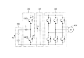
図1は本発明の第1の実施形態の負荷機駆動装置を示すブロック図であり、図中、1は電気自動車に適用する負荷駆動装置としての電動機駆動装置である。この電動機駆動装置1は、バッテリで構成される直流電源2と、この直流電源2の正極側及び負極側から導出された正極側ラインLp及び負極側ラインLnにそれぞれ並列に接続されたDC−DC変換部3、平滑回路4及びDC−AC変換部5を備えている。そして、DC−AC変換部5から出力される交流電力が交流電動機6に供給されている。この交流電動機6で発生される駆動トルクは、必要に応じて減速機構7を介し、さらにデファレンシャルギヤ8を介して駆動輪9に伝達される。
Hereinafter, embodiments of the present invention will be described with reference to the drawings.
FIG. 1 is a block diagram showing a load machine drive device according to a first embodiment of the present invention. In the figure, 1 is an electric motor drive device as a load drive device applied to an electric vehicle. The electric
直流電源2は、1ユニットが数Vのバッテリを数10直列に接続することで、数百Vのバッテリ電圧Vbを得るように構成されている。そして、直列に接続されたバッテリを2分割してバッテリユニットBUa及びBUbを構成している。そして、バッテリユニットBUaの正極側から正極側スイッチ回路SWpを介して正極側ラインLpが導出され、バッテリユニットBUbの負極側から負極側スイッチ回路SWnを介して負極側ラインLnが導出されている。さらに、バッテリユニットBUa及びBUbの接続点すなわち中間電位点Pmから中間電位ラインLmが導出されている。ここで、正極側スイッチ回路SWp及び負極側スイッチ回路SWnは、コンタクタのような機械式のスイッチやサイリスタ、絶縁ゲートバイポーラトランジスタ(IGBT)などの逆耐圧を有する半導体スイッチ素子を逆並列に接続したもので構成することができる。例えば、図2(a)に示すように、逆耐圧を有するIGBTa及びIGBTbを逆並列に接続した構成を適用するか、図2(b)に示すように、逆耐圧を有さないIGBTc及びIGBTdを直列に接続し、各IGBTc及びIGBTdに逆並列にダイオードDc及びDdを接続した構成を適用することが好ましい。
The
また、DC−DC変換部3は、双方向昇圧チョッパ回路の構成を有し、正極側ラインLpと中間電位ラインLmとの間に直列に接続された一対の例えばIGBTで構成されるスイッチング素子Q3a及びQ3bを備えている。これらスイッチング素子Q3a及びQ3bの接続点にはリアクトルLを介して直流電源2の中間電位ラインLmが接続されている。各スイッチング素子Q3a及びQ3bにはそれぞれダイオードD3a及びD3bが逆並列接続されている。
The DC-
さらに、平滑回路4は、正極側ラインLp及び負極側ラインLn間に接続された平滑用コンデンサCを備えており、この平滑用コンデンサCでDC−DC変換部3から出力される直流電力を平滑化する。この平滑用コンデンサCの両端の直流電圧EdがDC−AC変換部5に供給される。
Furthermore, the smoothing
さらにまた、DC−AC変換部5は、インバータ回路の構成を有し、正極側ラインLp及び負極側ラインLn間に並列に接続された3つのスイッチングアームSA21〜SA23を有する。これらスイッチングアームSA21〜23のそれぞれは、正極側ラインLp及び負極側ラインLn間に直列に接続された例えばIGBTで構成されるスイッチング素子Qja及びQjb(jは21〜23)と、各スイッチング素子Qja及びQjbに逆並列に接続されたダイオードDja及びDjbとを有する。そして、各スイッチング素子Qja及びQjbの接続点が交流出力点Pu,Pv及びPwとされて負荷としての交流電動機6の例えばスター結線されたコイルLu、Lv及びLwに接続されている。
Furthermore, the DC-
そして、上記正極側スイッチ回路SWp及び負極側スイッチ回路SWnのオンオフ制御と、DC−DC変換部3のスイッチング素子Q3a及びQ3b及びDC−AC変換部5のスイッチング素子Q21a〜23bのPWM(パルス幅変調)制御が、図3に示すように、制御装置11の制御部12によって行われる。ここで、制御部12には、交流電動機6の速度指令(又は周波数指令)Nm*が入力される。
The on / off control of the positive side switch circuit SWp and the negative side switch circuit SWn, and the PWM (pulse width modulation) of the switching elements Q3a and Q3b of the DC-
次に、上記第1の実施形態の動作を説明する。
今、車両が渋滞時走行程度の低速度(例えば0〜20km/h程度)で走行し、交流電動機6を、図4に示すように、交流電動機6の回転速度Nmを所定回転数N01以下に設定して低速回転駆動する場合には、図5(a)に示すように、例えば正極側スイッチ回路SWpを常時オフ状態とし、且つ負極側スイッチ回路SWnを常時オン状態としてバッテリユニットBUbを選択する。この制御状態では、バッテリユニットBUbの正極側がリアクトルLを介しスイッチング素子Q3aと逆並列に接続されたダイオードD3aを介して平滑回路4の平滑用コンデンサCの正極側に接続され、バッテリユニットBUbの負極側が負極側スイッチ回路SWnを介し負極側ラインLnを介して平滑回路4の平滑用コンデンサCの負極側に供給される。このため、バッテリユニットBUbは、バッテリ電圧Vbの半分の電圧Vb/2であるので、この電圧Vb/2が平滑用コンデンサCに充電されることになる。このため、平滑用コンデンサCの両端の正極側電位部Vp及び負極側電位部Vn間の直流電圧EdはVb/2となる。
Next, the operation of the first embodiment will be described.
Now, the vehicle travels at a low speed (for example, about 0 to 20 km / h) at the time of traffic jam, and the
この平滑回路4の直流電圧Ed(=Vb/2)がDC−AC変換部5の各スイッチングアームSA1〜SA3に供給されるので、これらスイッチングアームSA1〜SA3の各スイッチング素子Q21a〜Q23a及びQ21b〜Q23bを制御部12で、速度指令(又は周波数指令)Nm*に基づくデューティ比でPWM制御することにより、交流電動機6を低速回転駆動することができる。このため、交流電動機6をバッテリ電圧Vbの半分の電圧Vb/2がDC−AC変換部5に供給されて、このDC−AC変換部5の各スイッチング素子Q21a〜Q23a及びQ21b〜Q23bがPWM制御される。したがって、DC−AC変換部のスイッチング損失や、交流電動機6の高調波損失を低減することが可能となる。
Since the DC voltage Ed (= Vb / 2) of the smoothing
同様に、図5(b)に示すように、正極側スイッチ回路SWpを常時オン状態とし、負極側スイッチ回路SWnを常時オフ状態とすることにより、バッテリユニットBUaを選択する。このため、バッテリユニットBUaの正極側が正極側スイッチ回路SWpを介し、正極側ラインLpを介して平滑回路4の平滑用コンデンサCの正極側に接続される。一方、バッテリユニットBUaの負極側がリアクトルL及びダイオードD3bを介し、さらに負極側ラインLnを介して平滑用コンデンサCの負極側に接続される。このため、上述した図5(a)と同様に、平滑用コンデンサCの両端の直流電圧Edがバッテリ電圧Vbの半分の電圧Vb/2となり、この直流転圧Ed(=Vb/2)がDC−AC変換部5に供給される。そして、上述した図5(a)と同様にDC−AC変換部5の各スイッチング素子Q21a〜Q23a及びQ21b〜Q23bをPWM制御することにより、DC−AC変換部のスイッチング損失や、交流電動機6の高調波損失を低減することが可能となる。
Similarly, as shown in FIG. 5B, the battery unit BUa is selected by always turning on the positive switch circuit SWp and turning off the negative switch circuit SWn. For this reason, the positive side of the battery unit BUa is connected to the positive side of the smoothing capacitor C of the smoothing
また、交流電動機6の低速回転領域での一方のバッテリユニットBUa(またはBUb)に負担が集中するのを軽減するために、低速回転領域で図5(b)に示すバッテリユニットBUaを使用するモードaと、図5(a)に示すバッテリユニットBUbを使用するモードbとを時系列で交互に切換えるようにしても良い。
Further, a mode in which the battery unit BUa shown in FIG. 5B is used in the low-speed rotation region in order to reduce the burden on one battery unit BUa (or BUb) in the low-speed rotation region of the
次ぎに、車両が例えば市街地を走行する程度の中速度(20km/h〜70km/h程度)で走行し、交流電動機6の回転速度Nmを、図4における所定回転速度N01を超え所定回転速度N01より大きい回転速度N0以下となる中速回転領域で回転駆動する場合について説明する。
Next, the vehicle travels at a medium speed (about 20 km / h to 70 km / h), for example, so that the vehicle travels in an urban area, and the rotational speed Nm of the
この中速回転領域では、図6に示すように、正極側スイッチ回路SWp及び負極側スイッチ回路SWnの双方を常時オン状態に制御して、バッテリユニットBUa及びBUbを選択する。この制御状態では、バッテリユニットBUa及びBUbの電圧を加算したバッテリ電圧Vbが平滑回路4の平滑用コンデンサCに充電される。このため、平滑用コンデンサCの両端の直流電圧Edがバッテリ電圧Vbとなり、前述した低速回転駆動状態の倍の電圧がDC−AC変換部5に供給される。このため、DC−AC変換部5の各スイッチング素子Q21a〜Q23a及びQ21b〜Q23bをPWM制御することにより、交流電動機6を高電圧で回転駆動することができる。
In this medium speed rotation region, as shown in FIG. 6, both the positive electrode side switch circuit SWp and the negative electrode side switch circuit SWn are controlled to be always on to select the battery units BUa and BUb. In this control state, the smoothing capacitor C of the smoothing
この交流電動機6を中速回転駆動する状態では、前述した図12の従来例と同様の駆動方式となるが、回路的にはリアクトルLを介することがないとともに、DC−DC変換部3をPWM駆動することがない。このため、リアクトルLでの銅損や鉄損を防止することができるとともに、DC−DC変換部3でのスイッチング損失やオン損失を防止することができる。
In a state where the
次ぎに、例えば車両が高速道路を走行する高速度(例えば80km/h以上)で走行し、交流電動機6の回転速度Nmを、図4における所定回転速度N0を超え所定回転速度N0より大きい回転速度N1以下となる高速回転領域で回転駆動する場合について説明する。
Next, for example the vehicle is traveling at high speed running on an expressway (for example, 80 km / h or higher), the rotational speed Nm of
この高速回転領域では、図7に示すように、正極側スイッチ回路SWpを常時オン状態とし、負極側スイッチ回路SWnを常時オフ状態とすることにより、バッテリユニットBUbを選択する。そして、バッテリユニットBUbの正極側を中間電位ラインLm及びリアクトルLを介してDC−DC変換部3のスイッチング素子Q3a及びQ3bの接続点に接続し、負極側を負極側スイッチ回路SWnを介して負極ラインLnに接続する。
In this high-speed rotation region, as shown in FIG. 7, the battery unit BUb is selected by always turning on the positive switch circuit SWp and turning off the negative switch circuit SWn. Then, the positive side of the battery unit BUb is connected to the connection point of the switching elements Q3a and Q3b of the DC-
この状態で、DC−DC変換部3のスイッチング素子Q3BをPWM制御する。このとき、交流電動機6の回転速度Nmが所定回転速度N0であるときには、昇圧率αが“2”となるようにスイッチング素子Q3bのゲートに供給するPWM信号のデューティ比を選択する。これにより、DC−DC変換部3でバッテリ電圧Vb/2をバッテリ電圧Vbまで昇圧し、この昇圧電圧で平滑回路4の平滑用コンデンサCを充電する。このため、平滑用コンデンサCの両端の直流電圧Edがバッテリ電圧Vbと等しくなり、前述した中速回転領域の直流電圧Edと等しくなる。
In this state, the switching element Q3B of the DC-
この昇圧動作は、DC−DC変換部3のスイッチング素子Q3aを常時オフ状態とし、且つスイッチング素子Q3bをオン状態とすることにより、リアクトル7に電流が流れる。この状態から、スイッチング素子Q3bをオフ状態とすることにより、リアクトル7には電流が流れ続けるように逆起電圧が生じ、この逆起電圧がダイオードD3aを通じて平滑回路4の平滑用コンデンサCに充電されて昇圧が行われる。
In this step-up operation, a current flows through the reactor 7 when the switching element Q3a of the DC-
その後、スイッチング素子Q3bに供給するPWM信号のデューティ比を増加させて、昇圧率αを“2”より徐々に増加させることにより、DC−DC変換部3から出力される直流電圧をバッテリ電圧Vbより徐々に増加させ、交流電動機6の回転速度Nmを所定回転速度N0から徐々に増加させる。
Thereafter, by increasing the duty ratio of the PWM signal supplied to the switching element Q3b and gradually increasing the step-up rate α from “2”, the DC voltage output from the DC-
そして、昇圧率αを増加させることにより、DC−DC変換部3から出力される直流電圧によって充電される平滑回路4の平滑用コンデンサCの直流電圧Edが予め設定された最大電圧EdMAXに達すると、以後はDC−DC変換部3の出力電圧を平滑用コンデンサCに設定された最大電圧EdMAXを維持するようにスイッチング素子Q3bのゲートに供給するPWM信号のデューティ比を固定する。
Then, by increasing the step-up rate α, the DC voltage Ed of the smoothing capacitor C of the smoothing
この交流電動機6を高速回転領域で回転駆動する場合には、回路的には前述した従来例と等しくなるが、入力電源となるバッテリ電圧VbがVb/2となることが異なる。このため、昇圧時のスイッチング素子Q3b及びダイオードD3aの負担とパワーの供給を行うバッテリユニットBUbの負担が従来方式に比較して大きくなる。
When the
このバッテリユニットBUbの負担増を解消するは、図8に示すように、中立電位ラインLmとバッテリユニットBUa及びBUbの中間電位点Pmとの間に正極側スイッチ回路SWp及び負極側スイッチ回路SWnと同様の中間電位スイッチ回路SWmを介挿するとともに、バッテリユニットBUa及び正極側スイッチ回路SWpの接続点とスイッチ回路SWm及びリアクトルLの接続点との間にバイパススイッチ回路SWaを設ける。 As shown in FIG. 8, the increase in the load on the battery unit BUb is achieved by connecting the positive side switch circuit SWp and the negative side switch circuit SWn between the neutral potential line Lm and the intermediate potential point Pm between the battery units BUa and BUb. A similar intermediate potential switch circuit SWm is inserted, and a bypass switch circuit SWa is provided between a connection point of the battery unit BUa and the positive side switch circuit SWp and a connection point of the switch circuit SWm and the reactor L.
この構成によると、交流電動機6を高速回転領域で回転駆動する場合には、正極側スイッチ回路SWp及び中間電位スイッチ回路SWmを常時オフ状態とし、負極側スイッチ回路SWn及びバイパススイッチ回路SWaを常時オン状態として、バッテリユニットBUa及びBUbを選択することにより、直流電源2から出力される電圧をバッテリ電圧Vbとする。
According to this configuration, when the
この場合には、DC−DC変換部3のスイッチング素子Q3bのゲートに供給するPWM信号のデューティ比を交流電動機6の回転速度Nmが所定値N0であるときに、昇圧率αが“1”となるように設定することにより、交流電動機6の回転速度Nmが所定値N0であるときに平滑用コンデンサCの両端の直流電圧Edをバッテリ電圧Vbと等しくすることができる。
In this case, when the rotational speed Nm of the
このように、図8の構成によれば、DC−DC変換部3のリアクトルLにバッテリ電圧Vbを供給することができるので、昇圧動作時のバッテリユニットBUa及びBUbの負担を等しくし、これらバッテリユニットBUa及びBUbの負担とDC−DC変換部のスイッチング素子Q3b及びダイオードD3aの負担とを前述した図12に示す従来例と等しくすることができる。
As described above, according to the configuration of FIG. 8, since the battery voltage Vb can be supplied to the reactor L of the DC-
また、交流電動機6の高速回転領域での一方のバッテリユニットBUbの負担増を軽減するために、高速回転領域で図9(a)に示すバッテリユニットBUaを使用するモードaと、図9(b)に示すバッテリユニットBUbを使用するモードbとを時系列で交互に切換えるようにしても良い。
すなわち、モードaでは、正極側スイッチ回路SWpを常時オン状態とし、負極側スイッチ回路SWnを常時オフ状態としてバッテリユニットBUaを選択し、且つDC−DC変換部3のスイッチング素子Q3bを常時オフ状態とし、スイッチング素子Q3aのゲートに交流電動機6の回転速度Nmに応じたデューティ比のPWM信号を供給する。
Further, in order to reduce the burden on one battery unit BUb in the high-speed rotation region of the
That is, in mode a, the positive side switch circuit SWp is always on, the negative side switch circuit SWn is always off, the battery unit BUa is selected, and the switching element Q3b of the DC-
これにより、スイッチング素子Q3aがオン状態であるときには、バッテリユニットBUaから正極側スイッチ回路SWp、スイッチング素子Q3a、リアクトルLを介してバッテリユニットBUaの負極側に至る閉回路が構成されて、リアクトルLに電流が流れる。 Thus, when the switching element Q3a is in the on state, a closed circuit is formed from the battery unit BUa to the negative electrode side of the battery unit BUa via the positive side switch circuit SWp, the switching element Q3a, and the reactor L. Current flows.
その後、スイッチング素子Q3aがオフ状態となると、リアクトルLには電流が流れ続けるように逆起電圧が生じる。このとき、バッテリユニットBUaの正極側が正極スイッチ側回路SWp及び正極側ラインLp経て平滑用コンデンサCの正極側に接続され、この平滑用コンデンサCの負極側が負極側ラインLn、ダイオードD3b、リアクトルL及び中間電位ラインLmを介してバッテリユニットBUbの負極側に接続される。このため、リアクトルLに生じた逆起電圧がバッテリユニットBUaのバッテリ電圧Vb/2に加算されて平滑回路4の平滑コンデンサCに充電される。このため、平滑コンデンサCの両端の直流電圧Edがバッテリ電圧Vb/2を昇圧した電圧となり、この直流電圧EdがDC−AC変換部5に供給されることにより、このDC−AC変換部5でスイッチング素子Q21a〜Q23a及びQ21b〜Q23bをPWM制御して交流電動機を高速駆動する。
Thereafter, when switching element Q3a is turned off, a counter electromotive voltage is generated in reactor L so that a current continues to flow. At this time, the positive side of the battery unit BUa is connected to the positive side of the smoothing capacitor C via the positive switch side circuit SWp and the positive side line Lp, and the negative side of the smoothing capacitor C is connected to the negative side line Ln, the diode D3b, the reactor L, and The battery unit BUb is connected to the negative electrode side via the intermediate potential line Lm. For this reason, the counter electromotive voltage generated in the reactor L is added to the battery voltage Vb / 2 of the battery unit BUa, and the smoothing capacitor C of the smoothing
また、モードbでは、前述した図7と同様の昇圧動作となる。
そして、これらモードa及びモードbを時間系列で交互に動作させることにより、バッテリユニットBUa及びBUbの負担を均等化することができるとともに、DC−DC変換部3におけるスイッチング素子Q3a及びQ3bとダイオードD3a及びD3bの負担も均等化することができる。このように、スイッチング素子Q3a及びQ3bとダイオードD3a及びD3bの負担を均等化することができるので、半導体チップの温度上昇抑制が可能となり、半導体チップの信頼性の向上を図ることができ可能となる。
In mode b, the boosting operation is the same as in FIG.
Then, by alternately operating the mode a and the mode b in time series, the burden on the battery units BUa and BUb can be equalized, and the switching elements Q3a and Q3b and the diode D3a in the DC-
因みに、前述した図15に示す従来例の構成でも、昇圧時には、DC−DC変換回路で構成される双方向昇圧チョッパ部101を構成するスイッチング素子IGBT2をオン状態としたときに、リアクトルLに電流が流れ、スイッチング素子IGBT2をオフ状態に反転させることにより、リアクトルLには電流が流れ続けるように逆起電圧が生じ、この逆起電圧がダイオードD1を通じて電解コンデンサ102に充電される。このため、スイッチング素子IGBT2及びダイオードD1のみが動作状態となり負担が、非動作状態となるスイッチング素子IGBT1及びダイオードD2に対して大きくなり、半導体の負担が不均等となる。
Incidentally, even in the configuration of the conventional example shown in FIG. 15 described above, when the switching element IGBT2 constituting the bidirectional
また、交流電動機6の回転速度Nmを所定回転速度N1を超えて回転駆動する場合には、前述した従来例と同様に、DC−AC変換部5のスイッチング素子Q21a〜Q23a及びQ21b〜Q23bをPWM制御から1パルス制御への移行や、弱め界磁制御を行うことにより、対応している。
Further, when rotating the rotational speed Nm of
さらに、車両が制動状態となったり、下り坂を走行する状態となったりして、交流電動機6が発電機として動作する状態となった回生動作時には、発電電力がDC−AC変換部5からDC−DC変換部3に供給され、このDC−DC変換部3で降圧されてバッテリユニットBUa及びBUbに充電電流として供給される。
Further, during the regenerative operation in which the vehicle is in a braking state or traveling downhill and the
また、上記第1の実施形態においては、交流電動機6を中速回転領域で駆動する場合に、平滑回路4の平滑用コンデンサCの両端の直流電圧Ebを交流電動機6の回転速度にかかわらずバッテリ電圧Vbに等しく設定した場合について説明した。しかしながら、上記構成に限定されるものではなく、図8に示す回路構成を適用して、中速回転領域で、スイッチ回路SWp及びSWaを常時オフ状態として、スイッチ回路SWn及びSWmを常時オン状態として、バッテリユニットBUbを選択して、DC−DC変換部3の出力電圧をVb/2から徐々に昇圧する。これにより、図4で点線図示のように回転速度Nmの増加に応じて平滑用コンデンサCの両端の直流電圧EdをVb/2から徐々に増加させるようにしても良い。このとき、回転数Nmが所定回転速度N0に達したときに、スイッチ回路SWmを常時オフ状態に切換えるとともに、スイッチ回路SWaを常時オン状態に切換えて、バッテリ電圧Vbの昇圧状態に切換える。
In the first embodiment, when the
さらに、バッテリユニットBUbが故障した場合には、図10(a)に示すように、正極側スイッチ回路SWpを常時オン状態とし、負極側スイッチ回路SWnを常時オフ状態とすることで、前述した図9(a)に示すモードaと同様の構成とすることができ、交流電動機6の駆動制御を正常状態で継続することができる。
Further, when the battery unit BUb fails, as shown in FIG. 10A, the positive switch circuit SWp is always turned on and the negative switch circuit SWn is always turned off. It can be set as the structure similar to the mode a shown to 9 (a), and drive control of the
逆に、バッテリユニットBUaが故障した場合には、図10(b)に示すように、正極側スイッチ回路SWpを常時オフ状態とし、負極側スイッチ回路SWnを常時オン状態とすることで、前述した図9(b)に示すモードbと同様の構成とすることができ、交流電動機6の駆動制御を正常状態で継続することができる。
このように、バッテリユニットBUa及びBUbの一方が故障した場合でも、交流電動機6の正常運転を継続することが可能となるため、自動車としての信頼性向上を図ることが可能となる。
Conversely, when the battery unit BUa fails, as shown in FIG. 10B, the positive switch circuit SWp is always turned off and the negative switch circuit SWn is always turned on, as described above. It can be set as the structure similar to the mode b shown in FIG.9 (b), and drive control of the
Thus, even when one of the battery units BUa and BUb fails, the normal operation of the
以上説明したように、交流電動機6の回転速度Nmの回転速度領域に応じて正極側スイッチ回路SWp、負極側スイッチ回路SWn、DC−DC変換部3及びDC−AC変換部5を制御するには制御装置11の制御部12を図11に示すように構成する。
As described above, in order to control the positive side switch circuit SWp, the negative side switch circuit SWn, the DC-
すなわち、制御部12に、低速回転領域制御部21、中速回転領域制御部22及び高速回転領域制御部23と、これら低速回転領域制御部21、中速回転領域制御部22及び高速回転領域制御部23を選択する選択部24とを設ける。
ここで、低速回転領域制御部21では、前述した図5(a)又は(b)に示すように、正極側スイッチ回路SWp及び負極側スイッチ回路SWnをオンオフ制御し、且つDC−DC変換部3のスイッチング素子Q3a及びQ3bをオフ状態し、さらにDC−AC変換部5のスイッチング素子をPWM制御する。
That is, the
Here, as shown in FIG. 5A or 5B, the low-speed rotation
中速回転領域制御部22は、前述した図6に示すように、正極側スイッチ回路SWp及び負極側スイッチ回路SWnをともにオン状態に制御し、DC−DC変換部3のスイッチング素子Q3a及びQ3bをともにオフ状態に制御し、さらにDC−AC変換部5のスイッチング素子をPWM制御する。なお、中速回転領域制御部22としては、図8の構成としてスイッチング回路SWp、SWn、SWm、SWaをオンオフ制御するようにしてもよい。
As shown in FIG. 6 described above, the medium-speed rotation
高速回転領域制御部23は、図7に示すように、正極側スイッチ回路SWp及び負極側スイッチSWnの何れか一方をオン状態に制御し、他方をオフ状態に制御し、且つDC−DC変換部3のスイッチング素子Q3a及びQ3bの一方をPWM制御することで昇圧制御し、さらにDC−AC変換部5のスイッチング素子をPWM制御する。この高速回転領域制御部23では、昇圧制御を図9(a)及び(b)に示すようにモードa及びモードbを時間系列で交互に制御するようにしてもよい。
As shown in FIG. 7, the high-speed rotation
また、選択部24は、非反転入力側に回転速度指令Nm*が入力された2つのコンパレータ25及び26を有するウィンドコンパレータ27を備えている。各コンパレータ25及び26の反転入力側には個別に所定回転速度N01及びN0が入力されている。
したがって、コンパレータ25は回転速度指令Nm*が所定回転速度N01未満であるときには論理値“0”となり、回転速度指令Nm*が所定回転速度N01以上であるときには論理値“1”となる選択信号SL1を出力する。
The
Accordingly, the
また、コンパレータ25は、回転速度指令値Nm*が所定回転速度N0未満であるときには論理値“0”となり、回転速度指令Nm*が所定回転速度N0以上であるときには論理値“1”となる選択信号SL2を出力する。
そして、選択信号SL1及びSL2が選択信号SL1及びSL2の双方の入力側が反転入力とされたアンド回路28、選択信号SL1の入力側が反転入力とされたアンド回路29及びアンド回路30に供給されている。
Further, the
The selection signals SL1 and SL2 are supplied to an AND
そして、アンド回路28の出力が低速回転領域制御部21に供給され、アンド回路29の出力が中速回転領域制御部22に供給され、アンド回路30の出力が高速回転領域制御部23に供給され、各低速回転領域制御部21、中速回転領域制御部22及び高速回転領域制御部23が入力されるアンド出力が論理値“1”であるときに動作状態となるように構成されている。
The output of the AND
したがって、回転速度指令Nm*が所定回転速度N01より小さい場合には、コンパレータ25及び26から出力される選択信号SL1及びSL2がともに論理値“0”となる。このため、アンド回路28のみが論理値“1”を出力するので、低速回転領域制御部21のみが動作状態となって、交流電動機6を低速回転駆動する。
Thus, the rotational speed command Nm * is when a predetermined rotational speed N 01 is less than the selection signal SL1 and SL2 output from the
また、回転速度指令Nm*が所定回転速度N01以上で、所定回転速度N0未満であるときには、コンパレータ25から出力される選択信号SL1が論理値“1”となり、コンパレータ26から出力される選択信号SL2が論理値“0”となる。このため、アンド回路29のみが論理値“1”を出力するので、中速回転領域制御部22のみが動作状態となって、交流電動機6を中速回転駆動する。
When the rotation speed command Nm * is equal to or higher than the predetermined rotation speed N 01 and lower than the predetermined rotation speed N 0 , the selection signal SL1 output from the
さらに、回転速度指令Nm*が所定回転速度N0以上であるときには、コンパレータ25から出力される選択信号SL1が論理値“1”となり、コンパレータ26から出力される選択信号SL2も論理値“1”となる。このため、アンド回路30のみが論理値“1”を出力するので、高速回転領域制御部23のみが動作状態となって、交流電動機6を高速回転駆動する。
Further, when the rotational speed command Nm * is equal to or higher than the predetermined rotational speed N 0 , the selection signal SL1 output from the
また、制御装置11の制御部12で、バッテリユニットUBa及びUBbの故障も考慮する場合には、図12に示すように、バッテリユニットBUa及びBUbのそれぞれの端子電圧Va及びVbを検出して故障の有無を検出するバッテリ故障検出部31a及び31bを設け、これらバッテリ故障検出部31a及び31bでバッテリ故障を検出したときに出力されるバッテリ故障検出信号BAa及びBAbを制御部12に供給する。そして、制御部12では、図13に示すように、バッテリユニットBUbが故障したときに制御を行うユニットBUb故障時制御部32と、バッテリユニットBUaが故障したときに制御を行うユニットBUa故障時制御部33と、バッテリユニットBUa及びBUbが正常であるときに制御を行う前述した図11の構成を有する正常時制御部34とを備えている。
Further, when the
ここで、ユニットBUb故障時制御部32は、前述した図10(a)に示すように正極側スイッチ回路SWpを常時オン状態とし、負極側スイッチ回路SWnを常時オフ状態としてバッテリユニットBUaを選択し、且つDC−DC変換部3のスイッチング素子Q3aをPWM制御し、さらにDC−AC変換部5の各スイッチング素子をPWM制御する。
また、ユニットBUa故障時制御部33は、前述した図10(b)に示すように正極側スイッチ回路SWpを常時オフ状態とし、負極側スイッチ回路SWnを常時オン状態としてバッテリユニットBUbを選択し、且つDC−DC変換部3のスイッチング素子Q3bをPWM制御し、さらにDC−AC変換部5の各スイッチング素子をPWM制御する。
Here, the unit BUb
Further, the unit BUa
そして、選択スイッチ回路35にバッテリ故障検出信号BAa及びBAbが供給され、バッテリ故障検出信号BAa及びBAbがともに論理値“0”であるときには正常時制御部34が選択されて、スイッチ回路SWp,SWn、DC−DC変換部3及びDC−AC変換部5が制御される。また、バッテリ故障検出信号BAaが論理値“0”でバッテリ故障検出信号BAaが論理値“1”であるときには選択スイッチ回路35でユニットBUb故障時制御部32が選択されて、スイッチ回路SWp,SWn、DC−DC変換部3及びDC−AC変換部5が制御される。さらに、バッテリ故障検出信号BAaが論理値“1”でバッテリ故障検出信号BAaが論理値“0”であるときには選択スイッチ回路35でユニットBUa故障時制御部33が選択されて、スイッチ回路SWp,SWn、DC−DC変換部3及びDC−AC変換部5が制御される。
Then, the battery failure detection signals BAa and BAb are supplied to the
このように、制御装置11の制御部12を図12及び図13の構成とすることにより、直流電源2のバッテリユニットBUa及びBUbが正常である場合には、回転速度指令Nm*に応じて交流電動機6を回転速度制御し、バッテリユニットBUa及びBUbの一方が故障した場合には、正常なバッテリユニットを使用して交流電動機6を正常な回転速度制御を継続することができる。
In this way, by configuring the
なお、上記実施形態においては、DC−DC変換部3を構成するスイッチング素子Q3a及びQ3b間にバッテリユニットBUa及びBUb間の中間電位点PmをリアクトルLを介して接続する場合について説明した。しかしながら、本発明は上記構成に限定されるものではなく、図14に示すように、リアクトルLの容量の半分の容量のリアクトルLa及びLbに分割し、リアクトルLaを正極側スイッチ回路SWp及びDC−DC変換部3のスイッチング素子Q3aのコレクタ間の正極側ラインLpに介挿し、リアクトルLbを負極側スイッチ回路SWn及びDC−DC変換部3のスイッチング素子Q3bのエミッタ間の負極側ラインLnに介挿するようにしても良い。この場合でも、上述した実施形態と同様の作用効果を得ることができる。
In the above embodiment, the case where the intermediate potential point Pm between the battery units BUa and BUb is connected via the reactor L between the switching elements Q3a and Q3b constituting the DC-
また、上記実施形態においては、直流電源2としてバッテリユニットBUa及びBUbを適用した場合について説明したが、これに限定されるものでなく、2組の燃料電池ユニットや、2組の太陽電池ユニット等の他の直流電源ユニットで構成することもできる。さらには、バッテリユニット、燃料電池ユニット、太陽電池ユニット等の異なるユニット同士を接続して直流電源2を構成するようにしてもよい。
Moreover, in the said embodiment, although the case where battery unit BUa and BUb were applied as
さらに、上記実施形態においては、スイッチング素子としてIGBTを適用した場合について説明したが、これに限定されるものではなく、使用電力に応じてパワーMOSFET、ゲートターンオフサイリスタ(GTO)、静電誘導型トランジスタ(SIT)等の任意のスイッチング素子を適用することができる。
さらにまた、上記実施形態においては、本発明を電気自動車に適用した場合について説明したが、これに限定されるものではなく、電気自動車の交流電動機以外の交流負荷を直流電源2で駆動する負荷駆動装置にも本発明を適用することができる。
Furthermore, in the above-described embodiment, the case where the IGBT is applied as the switching element has been described. However, the present invention is not limited to this, and a power MOSFET, a gate turn-off thyristor (GTO), a static induction transistor is used according to the power used. Any switching element such as (SIT) can be applied.
Furthermore, in the above-described embodiment, the case where the present invention is applied to an electric vehicle has been described. However, the present invention is not limited to this, and a load drive that drives an AC load other than an AC motor of the electric vehicle with a
1…電動機駆動装置、2…直流電源、BUa,BUb…バッテリユニット、SWp…正極側スイッチ回路、SWn…負極側スイッチ回路、Lp…正極側ライン、Ln…負極側ライン、Lm…中間電位ライン、3…DC−DC変換部、L,La,Lb…リアクトル、4…平滑回路、C…平滑用コンデンサ、5…DC−AC変換部、6…交流電動機、11…制御装置、12…制御部、21…低速回転領域制御部、22…中速回転領域制御部、23…高速回転領域制御部、24…選択部、31a,31b…バッテリ故障検出部、32…ユニットBUb故障時制御部、33…ユニットBUb故障時制御部、34…正常時制御部
DESCRIPTION OF
Claims (7)
前記直流電源の正極側及び負極側にそれぞれ正極側スイッチ回路及び負極側スイッチ回路を介して接続された正極ライン及び負極ラインと、
前記正極ライン及び前記負極ライン間に直列に接続した少なくとも2つのスイッチング素子を有するDC−DC変換部と、
前記正極側ライン及び前記負極側ライン間に前記DC−DC変換部と並列に接続された平滑用コンデンサを有する平滑回路と、
該平滑回路の直流電力を交流電力に変換して電動機に供給するDC−AC変換部とを備え、
前記DC−DC変換部は、前記直流電源の中間電位と前記スイッチング素子間の接続点とを中間電位ラインで接続し、該中間電位ラインと前記正極側ライン及び負極側ラインとの一方にリアクトルを介挿した構成を有し、
前記正極ラインおよび負極ラインに介挿した正極側スイッチ回路および負極側スイッチ回路と、前記DC−DC変換部の2つのスイッチング素子とのオン・オフを制御して、少なくとも前記直流電源の電圧と、前記DC−DC変換部で昇圧した電圧とを選択的に前記DC−AC変換部へ供給する制御部を備えた
ことを特徴とする負荷駆動装置。 A load driving device that drives an AC motor using a DC power source,
A positive line and a negative line connected to a positive side and a negative side of the DC power source via a positive side switch circuit and a negative side switch circuit, respectively;
A DC-DC converter having at least two switching elements connected in series between the positive electrode line and the negative electrode line;
A smoothing circuit having a smoothing capacitor connected in parallel with the DC-DC converter between the positive electrode side line and the negative electrode side line;
A DC-AC converter that converts the DC power of the smoothing circuit into AC power and supplies the motor to the motor,
The DC-DC conversion unit connects an intermediate potential of the DC power source and a connection point between the switching elements by an intermediate potential line, and a reactor is connected to one of the intermediate potential line and the positive electrode side line and the negative electrode side line. have a structure in which interposed,
Controlling ON / OFF of the positive side switch circuit and the negative side switch circuit interposed between the positive line and the negative line, and the two switching elements of the DC-DC converter, and at least the voltage of the DC power supply, A load driving device comprising a control unit that selectively supplies the voltage boosted by the DC-DC conversion unit to the DC-AC conversion unit .
Priority Applications (2)
| Application Number | Priority Date | Filing Date | Title |
|---|---|---|---|
| JP2009168836A JP5493532B2 (en) | 2009-07-17 | 2009-07-17 | Load driving device and electric vehicle using the same |
| US12/838,414 US8297389B2 (en) | 2009-07-17 | 2010-07-16 | Load driving system and electric vehicle using the system |
Applications Claiming Priority (1)
| Application Number | Priority Date | Filing Date | Title |
|---|---|---|---|
| JP2009168836A JP5493532B2 (en) | 2009-07-17 | 2009-07-17 | Load driving device and electric vehicle using the same |
Publications (2)
| Publication Number | Publication Date |
|---|---|
| JP2011024370A JP2011024370A (en) | 2011-02-03 |
| JP5493532B2 true JP5493532B2 (en) | 2014-05-14 |
Family
ID=43464493
Family Applications (1)
| Application Number | Title | Priority Date | Filing Date |
|---|---|---|---|
| JP2009168836A Active JP5493532B2 (en) | 2009-07-17 | 2009-07-17 | Load driving device and electric vehicle using the same |
Country Status (2)
| Country | Link |
|---|---|
| US (1) | US8297389B2 (en) |
| JP (1) | JP5493532B2 (en) |
Families Citing this family (24)
| Publication number | Priority date | Publication date | Assignee | Title |
|---|---|---|---|---|
| JP5493532B2 (en) * | 2009-07-17 | 2014-05-14 | 富士電機株式会社 | Load driving device and electric vehicle using the same |
| US9780716B2 (en) | 2010-11-19 | 2017-10-03 | General Electric Company | High power-density, high back emf permanent magnet machine and method of making same |
| JP5264941B2 (en) * | 2011-01-21 | 2013-08-14 | 本田技研工業株式会社 | Electric vehicle power supply |
| JP5264940B2 (en) * | 2011-01-21 | 2013-08-14 | 本田技研工業株式会社 | Electric vehicle power supply |
| FR2973967B1 (en) * | 2011-04-08 | 2014-01-03 | Valeo Sys Controle Moteur Sas | METHOD FOR CONTROLLING A VOLTAGE INVERTER AND ASSOCIATED DEVICE |
| WO2013102960A1 (en) * | 2012-01-05 | 2013-07-11 | 株式会社 東芝 | Control device for electric vehicle, and electric vehicle |
| DE102012200804A1 (en) * | 2012-01-20 | 2013-07-25 | Continental Automotive Gmbh | On-board network and method for operating a vehicle electrical system |
| JP5999526B2 (en) * | 2012-03-30 | 2016-09-28 | 富士電機株式会社 | Power converter |
| DE102012106033A1 (en) * | 2012-07-05 | 2014-01-09 | Halla Visteon Climate Control Corporation 95 | A method of operating an inverter of an electrical refrigerant compressor using intermediate circuit electrolytic capacitors |
| US10286787B2 (en) * | 2013-09-27 | 2019-05-14 | Siemens Industry, Inc. | System and method for all electrical operation of a mining haul truck |
| JP5962639B2 (en) * | 2013-12-04 | 2016-08-03 | 株式会社デンソー | AC power supply switching device |
| DE102014203550A1 (en) * | 2014-02-27 | 2015-08-27 | Robert Bosch Gmbh | Electric drive system |
| DE102014203553A1 (en) * | 2014-02-27 | 2015-08-27 | Robert Bosch Gmbh | Electric drive system |
| US9684037B2 (en) * | 2014-05-27 | 2017-06-20 | Power Measrements, LLC | Devices and methods for testing the energy measurement accuracy, billing accuracy, functional performance and safety of electric vehicle charging stations |
| US10056851B2 (en) * | 2014-05-30 | 2018-08-21 | Eaton Corporation | System and method for induction motor speed estimation using a soft starter system |
| WO2018043480A1 (en) * | 2016-09-01 | 2018-03-08 | 国立大学法人筑波大学 | Load driving circuit, load driving system, and load driving method |
| BR112019006965B1 (en) | 2016-10-05 | 2023-11-21 | Voltu Motor, Inc | ELECTRICAL SYSTEM FOR CONTROLING AN ELECTRIC VEHICLE CONFIGURED TO OPERATE IN A PLURALITY OF MODES AND ELECTRIC VEHICLE |
| EP3407459A1 (en) * | 2017-05-25 | 2018-11-28 | Siemens Aktiengesellschaft | Power supply system and method |
| US10110103B1 (en) * | 2017-06-21 | 2018-10-23 | GM Global Technology Operations LLC | Electric drive system enhancement using a DC-DC converter |
| US10381834B1 (en) * | 2018-03-08 | 2019-08-13 | Omron Corporation | Power conditioner and power system |
| DE102019202334A1 (en) | 2019-02-21 | 2020-08-27 | Audi Ag | Drive device and method for operating a drive device |
| US10651740B1 (en) * | 2019-03-15 | 2020-05-12 | GM Global Technology Operations LLC | Buck-boost converter for an electric drive |
| US11254223B2 (en) * | 2019-11-06 | 2022-02-22 | GM Global Technology Operations LLC | Operating mode optimization for electric propulsion system with downsized DC-DC converter |
| EP4159517A4 (en) * | 2020-05-27 | 2023-12-20 | Denso Corporation | Power supply system |
Family Cites Families (19)
| Publication number | Priority date | Publication date | Assignee | Title |
|---|---|---|---|---|
| JPH0813171B2 (en) * | 1987-06-26 | 1996-02-07 | 株式会社ユタカ電機製作所 | Stabilized power supply |
| JPH0624357U (en) * | 1992-08-20 | 1994-03-29 | 株式会社アイチコーポレーション | Power supply |
| JP3132648B2 (en) * | 1996-09-20 | 2001-02-05 | 富士電機株式会社 | Gate drive circuit in power converter |
| US6554088B2 (en) * | 1998-09-14 | 2003-04-29 | Paice Corporation | Hybrid vehicles |
| JP3644531B2 (en) * | 1999-07-06 | 2005-04-27 | 富士電機機器制御株式会社 | Arm-on detection circuit for on-delay compensation |
| JP4489238B2 (en) | 2000-03-29 | 2010-06-23 | 正行 服部 | Electric motor control device |
| US6683499B2 (en) * | 2000-12-27 | 2004-01-27 | Emhiser Research, Inc. | Divided-voltage fet power amplifiers |
| JP2002330554A (en) * | 2001-04-27 | 2002-11-15 | Kobelco Contstruction Machinery Ltd | Power control device for hybrid vehicle and hybrid construction machine equipped with the power control device |
| JP2003324942A (en) * | 2002-05-08 | 2003-11-14 | Toyota Motor Corp | Voltage converter, method for driving voltage converter and computer readable recording medium recording program for performing drive of voltage converter at computer |
| JP3931734B2 (en) | 2002-06-05 | 2007-06-20 | トヨタ自動車株式会社 | Electric load drive |
| JP3986933B2 (en) * | 2002-09-20 | 2007-10-03 | 本田技研工業株式会社 | Power supply |
| US7602626B2 (en) * | 2005-02-25 | 2009-10-13 | Mitsubishi Electric Corporation | Power conversion apparatus |
| JP2008193779A (en) * | 2007-02-02 | 2008-08-21 | Fuji Electric Systems Co Ltd | Semiconductor module |
| JP4893368B2 (en) * | 2007-02-28 | 2012-03-07 | パナソニック株式会社 | Power supply |
| JP5352182B2 (en) * | 2008-10-24 | 2013-11-27 | 本田技研工業株式会社 | Power supply device and power supply system for fuel cell vehicle |
| JP5493532B2 (en) * | 2009-07-17 | 2014-05-14 | 富士電機株式会社 | Load driving device and electric vehicle using the same |
| JP5494147B2 (en) * | 2010-04-06 | 2014-05-14 | 富士電機株式会社 | Power semiconductor module and power converter using the same |
| JP5440335B2 (en) * | 2010-04-06 | 2014-03-12 | 富士電機株式会社 | Power semiconductor module and power converter using the same |
| JP2012029429A (en) * | 2010-07-22 | 2012-02-09 | Fuji Electric Co Ltd | Three level power conversion device |
-
2009
- 2009-07-17 JP JP2009168836A patent/JP5493532B2/en active Active
-
2010
- 2010-07-16 US US12/838,414 patent/US8297389B2/en active Active
Also Published As
| Publication number | Publication date |
|---|---|
| US8297389B2 (en) | 2012-10-30 |
| US20110011658A1 (en) | 2011-01-20 |
| JP2011024370A (en) | 2011-02-03 |
Similar Documents
| Publication | Publication Date | Title |
|---|---|---|
| JP5493532B2 (en) | Load driving device and electric vehicle using the same | |
| JP5359637B2 (en) | Power converter | |
| EP2538543B1 (en) | Power conversion apparatus | |
| US8310084B2 (en) | Device and method for controlling a power shunt circuit, hybrid vehicle having same | |
| JP5365586B2 (en) | Power converter | |
| JP6426426B2 (en) | Motor drive | |
| US9725007B2 (en) | Electric vehicle and control method therefor | |
| US11431184B2 (en) | Power supply device | |
| JP6636905B2 (en) | Power converter | |
| JP2014087105A (en) | Power conversion device | |
| JP2006340448A (en) | Motor controller | |
| JP6744836B2 (en) | Power conversion device, electric vehicle, and power conversion method | |
| JPH05308778A (en) | Inverter for driving electric car | |
| JP5400956B2 (en) | Power converter | |
| JP5444925B2 (en) | Power converter | |
| JP4395136B2 (en) | Electric vehicle power storage device and power storage device system | |
| WO2023112220A1 (en) | Power conversion device | |
| JP2012039873A (en) | Driving control device and electric rolling stock | |
| JPH114505A (en) | Controller for electric rolling stock | |
| JP5454218B2 (en) | Electric motor drive | |
| JP5986034B2 (en) | Power conversion system for auxiliary machine and control method | |
| JP2022084197A (en) | Motor system | |
| JP2009254033A (en) | Drive for power inverter circuit | |
| JP2019205247A (en) | Inverter |
Legal Events
| Date | Code | Title | Description |
|---|---|---|---|
| A711 | Notification of change in applicant |
Free format text: JAPANESE INTERMEDIATE CODE: A712 Effective date: 20110422 |
|
| A621 | Written request for application examination |
Free format text: JAPANESE INTERMEDIATE CODE: A621 Effective date: 20120116 |
|
| A977 | Report on retrieval |
Free format text: JAPANESE INTERMEDIATE CODE: A971007 Effective date: 20130517 |
|
| A131 | Notification of reasons for refusal |
Free format text: JAPANESE INTERMEDIATE CODE: A131 Effective date: 20130528 |
|
| A521 | Request for written amendment filed |
Free format text: JAPANESE INTERMEDIATE CODE: A523 Effective date: 20130724 |
|
| TRDD | Decision of grant or rejection written | ||
| A01 | Written decision to grant a patent or to grant a registration (utility model) |
Free format text: JAPANESE INTERMEDIATE CODE: A01 Effective date: 20140204 |
|
| A61 | First payment of annual fees (during grant procedure) |
Free format text: JAPANESE INTERMEDIATE CODE: A61 Effective date: 20140217 |
|
| R150 | Certificate of patent or registration of utility model |
Ref document number: 5493532 Country of ref document: JP Free format text: JAPANESE INTERMEDIATE CODE: R150 |
|
| R250 | Receipt of annual fees |
Free format text: JAPANESE INTERMEDIATE CODE: R250 |
|
| R250 | Receipt of annual fees |
Free format text: JAPANESE INTERMEDIATE CODE: R250 |
|
| R250 | Receipt of annual fees |
Free format text: JAPANESE INTERMEDIATE CODE: R250 |
|
| R250 | Receipt of annual fees |
Free format text: JAPANESE INTERMEDIATE CODE: R250 |
|
| R250 | Receipt of annual fees |
Free format text: JAPANESE INTERMEDIATE CODE: R250 |
|
| R250 | Receipt of annual fees |
Free format text: JAPANESE INTERMEDIATE CODE: R250 |
|
| R250 | Receipt of annual fees |
Free format text: JAPANESE INTERMEDIATE CODE: R250 |