JP5481305B2 - Output distribution controller - Google Patents
Output distribution controller Download PDFInfo
- Publication number
- JP5481305B2 JP5481305B2 JP2010172756A JP2010172756A JP5481305B2 JP 5481305 B2 JP5481305 B2 JP 5481305B2 JP 2010172756 A JP2010172756 A JP 2010172756A JP 2010172756 A JP2010172756 A JP 2010172756A JP 5481305 B2 JP5481305 B2 JP 5481305B2
- Authority
- JP
- Japan
- Prior art keywords
- secondary battery
- output distribution
- group
- output
- power
- Prior art date
- Legal status (The legal status is an assumption and is not a legal conclusion. Google has not performed a legal analysis and makes no representation as to the accuracy of the status listed.)
- Expired - Fee Related
Links
Images


Classifications
-
- H—ELECTRICITY
- H02—GENERATION; CONVERSION OR DISTRIBUTION OF ELECTRIC POWER
- H02J—CIRCUIT ARRANGEMENTS OR SYSTEMS FOR SUPPLYING OR DISTRIBUTING ELECTRIC POWER; SYSTEMS FOR STORING ELECTRIC ENERGY
- H02J3/00—Circuit arrangements for ac mains or ac distribution networks
- H02J3/28—Arrangements for balancing of the load in a network by storage of energy
- H02J3/32—Arrangements for balancing of the load in a network by storage of energy using batteries with converting means
-
- H—ELECTRICITY
- H02—GENERATION; CONVERSION OR DISTRIBUTION OF ELECTRIC POWER
- H02J—CIRCUIT ARRANGEMENTS OR SYSTEMS FOR SUPPLYING OR DISTRIBUTING ELECTRIC POWER; SYSTEMS FOR STORING ELECTRIC ENERGY
- H02J3/00—Circuit arrangements for ac mains or ac distribution networks
- H02J3/38—Arrangements for parallely feeding a single network by two or more generators, converters or transformers
- H02J3/46—Controlling of the sharing of output between the generators, converters, or transformers
- H02J3/466—Scheduling the operation of the generators, e.g. connecting or disconnecting generators to meet a given demand
-
- H—ELECTRICITY
- H02—GENERATION; CONVERSION OR DISTRIBUTION OF ELECTRIC POWER
- H02J—CIRCUIT ARRANGEMENTS OR SYSTEMS FOR SUPPLYING OR DISTRIBUTING ELECTRIC POWER; SYSTEMS FOR STORING ELECTRIC ENERGY
- H02J9/00—Circuit arrangements for emergency or stand-by power supply, e.g. for emergency lighting
-
- H—ELECTRICITY
- H02—GENERATION; CONVERSION OR DISTRIBUTION OF ELECTRIC POWER
- H02J—CIRCUIT ARRANGEMENTS OR SYSTEMS FOR SUPPLYING OR DISTRIBUTING ELECTRIC POWER; SYSTEMS FOR STORING ELECTRIC ENERGY
- H02J2300/00—Systems for supplying or distributing electric power characterised by decentralized, dispersed, or local generation
- H02J2300/20—The dispersed energy generation being of renewable origin
- H02J2300/22—The renewable source being solar energy
- H02J2300/24—The renewable source being solar energy of photovoltaic origin
-
- H—ELECTRICITY
- H02—GENERATION; CONVERSION OR DISTRIBUTION OF ELECTRIC POWER
- H02J—CIRCUIT ARRANGEMENTS OR SYSTEMS FOR SUPPLYING OR DISTRIBUTING ELECTRIC POWER; SYSTEMS FOR STORING ELECTRIC ENERGY
- H02J2300/00—Systems for supplying or distributing electric power characterised by decentralized, dispersed, or local generation
- H02J2300/20—The dispersed energy generation being of renewable origin
- H02J2300/28—The renewable source being wind energy
-
- H—ELECTRICITY
- H02—GENERATION; CONVERSION OR DISTRIBUTION OF ELECTRIC POWER
- H02J—CIRCUIT ARRANGEMENTS OR SYSTEMS FOR SUPPLYING OR DISTRIBUTING ELECTRIC POWER; SYSTEMS FOR STORING ELECTRIC ENERGY
- H02J2300/00—Systems for supplying or distributing electric power characterised by decentralized, dispersed, or local generation
- H02J2300/40—Systems for supplying or distributing electric power characterised by decentralized, dispersed, or local generation wherein a plurality of decentralised, dispersed or local energy generation technologies are operated simultaneously
-
- H—ELECTRICITY
- H02—GENERATION; CONVERSION OR DISTRIBUTION OF ELECTRIC POWER
- H02J—CIRCUIT ARRANGEMENTS OR SYSTEMS FOR SUPPLYING OR DISTRIBUTING ELECTRIC POWER; SYSTEMS FOR STORING ELECTRIC ENERGY
- H02J3/00—Circuit arrangements for ac mains or ac distribution networks
- H02J3/38—Arrangements for parallely feeding a single network by two or more generators, converters or transformers
- H02J3/381—Dispersed generators
-
- H—ELECTRICITY
- H02—GENERATION; CONVERSION OR DISTRIBUTION OF ELECTRIC POWER
- H02J—CIRCUIT ARRANGEMENTS OR SYSTEMS FOR SUPPLYING OR DISTRIBUTING ELECTRIC POWER; SYSTEMS FOR STORING ELECTRIC ENERGY
- H02J7/00—Circuit arrangements for charging or depolarising batteries or for supplying loads from batteries
- H02J7/34—Parallel operation in networks using both storage and other dc sources, e.g. providing buffering
- H02J7/35—Parallel operation in networks using both storage and other dc sources, e.g. providing buffering with light sensitive cells
-
- Y—GENERAL TAGGING OF NEW TECHNOLOGICAL DEVELOPMENTS; GENERAL TAGGING OF CROSS-SECTIONAL TECHNOLOGIES SPANNING OVER SEVERAL SECTIONS OF THE IPC; TECHNICAL SUBJECTS COVERED BY FORMER USPC CROSS-REFERENCE ART COLLECTIONS [XRACs] AND DIGESTS
- Y02—TECHNOLOGIES OR APPLICATIONS FOR MITIGATION OR ADAPTATION AGAINST CLIMATE CHANGE
- Y02E—REDUCTION OF GREENHOUSE GAS [GHG] EMISSIONS, RELATED TO ENERGY GENERATION, TRANSMISSION OR DISTRIBUTION
- Y02E10/00—Energy generation through renewable energy sources
- Y02E10/50—Photovoltaic [PV] energy
- Y02E10/56—Power conversion systems, e.g. maximum power point trackers
-
- Y—GENERAL TAGGING OF NEW TECHNOLOGICAL DEVELOPMENTS; GENERAL TAGGING OF CROSS-SECTIONAL TECHNOLOGIES SPANNING OVER SEVERAL SECTIONS OF THE IPC; TECHNICAL SUBJECTS COVERED BY FORMER USPC CROSS-REFERENCE ART COLLECTIONS [XRACs] AND DIGESTS
- Y02—TECHNOLOGIES OR APPLICATIONS FOR MITIGATION OR ADAPTATION AGAINST CLIMATE CHANGE
- Y02E—REDUCTION OF GREENHOUSE GAS [GHG] EMISSIONS, RELATED TO ENERGY GENERATION, TRANSMISSION OR DISTRIBUTION
- Y02E10/00—Energy generation through renewable energy sources
- Y02E10/70—Wind energy
- Y02E10/76—Power conversion electric or electronic aspects
-
- Y—GENERAL TAGGING OF NEW TECHNOLOGICAL DEVELOPMENTS; GENERAL TAGGING OF CROSS-SECTIONAL TECHNOLOGIES SPANNING OVER SEVERAL SECTIONS OF THE IPC; TECHNICAL SUBJECTS COVERED BY FORMER USPC CROSS-REFERENCE ART COLLECTIONS [XRACs] AND DIGESTS
- Y02—TECHNOLOGIES OR APPLICATIONS FOR MITIGATION OR ADAPTATION AGAINST CLIMATE CHANGE
- Y02E—REDUCTION OF GREENHOUSE GAS [GHG] EMISSIONS, RELATED TO ENERGY GENERATION, TRANSMISSION OR DISTRIBUTION
- Y02E70/00—Other energy conversion or management systems reducing GHG emissions
- Y02E70/30—Systems combining energy storage with energy generation of non-fossil origin
-
- Y—GENERAL TAGGING OF NEW TECHNOLOGICAL DEVELOPMENTS; GENERAL TAGGING OF CROSS-SECTIONAL TECHNOLOGIES SPANNING OVER SEVERAL SECTIONS OF THE IPC; TECHNICAL SUBJECTS COVERED BY FORMER USPC CROSS-REFERENCE ART COLLECTIONS [XRACs] AND DIGESTS
- Y02—TECHNOLOGIES OR APPLICATIONS FOR MITIGATION OR ADAPTATION AGAINST CLIMATE CHANGE
- Y02P—CLIMATE CHANGE MITIGATION TECHNOLOGIES IN THE PRODUCTION OR PROCESSING OF GOODS
- Y02P90/00—Enabling technologies with a potential contribution to greenhouse gas [GHG] emissions mitigation
- Y02P90/50—Energy storage in industry with an added climate change mitigation effect
Description
本発明の実施形態は、二次電池群が接続された電力系統に適用される出力配分制御装置および出力配分制御方法に関する。 Embodiments described herein relate generally to an output distribution control device and an output distribution control method applied to a power system to which a secondary battery group is connected.
近年、地球環境問題への関心の高まりから、太陽光発電や風力発電など自然エネルギーを利用した分散型電源の電力系統への連系が急増している。これらの自然エネルギーを利用した分散型電源は、天候・気象などの自然条件によって出力変動が生じやすく、連系している電力系統の周波数変動や電圧変動に悪影響を与えてしまう。そのため、一般に、二次電池などの電力貯蔵装置を用いて電力の充放電を行うことにより、自然エネルギーを利用した分散型電源の出力変動を補償することが行われている。 In recent years, due to increasing interest in global environmental problems, the interconnection of distributed power sources using natural energy such as solar power generation and wind power generation has increased rapidly. In these distributed power sources using natural energy, output fluctuations are likely to occur due to natural conditions such as weather and meteorological conditions, which adversely affects frequency fluctuations and voltage fluctuations of the connected power system. Therefore, in general, the output fluctuation of a distributed power source using natural energy is compensated by charging and discharging power using a power storage device such as a secondary battery.
なお、電力貯蔵装置に関する技術としては、例えば特許文献1〜5が挙げられる。 In addition, as a technique regarding an electric power storage apparatus, patent documents 1-5 are mentioned, for example.
電力貯蔵装置は一般に高価であり、これが大規模な太陽光発電等の普及の障害となっていたが、昨今、電気自動車やプラグイン・ハイブリッド自動車に備えられる二次電池を電力貯蔵装置として活用しようという動きが見られ、これによって太陽光発電等の電源に加え、電力貯蔵装置が一般家庭にまで益々普及してくることが予想される。 Power storage devices are generally expensive, and this has been an obstacle to the widespread use of large-scale solar power generation, etc., but nowadays, let's use secondary batteries equipped in electric vehicles and plug-in hybrid vehicles as power storage devices. As a result, in addition to power sources such as photovoltaic power generation, it is expected that power storage devices will become increasingly popular in ordinary households.
そのような状況のもとでは、各需要家は各二次電池を個別に使用することから、系統全体としてはそれら二次電池の余剰能力を活かしきない可能性がある。そのような余剰能力は、無駄なく活せるようにすることが望ましい。その一方で、自然エネルギーを利用する太陽光発電等の電源の出力変動を補償する観点から、各二次電池の制御余力を確保し、電力品質を確保することも求められる。 Under such circumstances, since each consumer uses each secondary battery individually, the entire system may not be able to utilize the surplus capacity of those secondary batteries. It is desirable to make use of such surplus capacity without waste. On the other hand, from the viewpoint of compensating for fluctuations in the output of a power source such as solar power generation that uses natural energy, it is also required to secure control power for each secondary battery and ensure power quality.
上記実情に鑑みると、二次電池群を有する電力系統において経済性の確保と電力品質の確保の両方を実現する技術の提示が望まれる。 In view of the above circumstances, it is desired to present a technology that realizes both securing of economy and securing of power quality in an electric power system having a secondary battery group.
本発明のある実施形態によれば、発電機群、負荷群、および二次電池群が接続された電力系統に適用される出力配分制御装置であって、少なくとも前記負荷群の需要を示す情報と、前記発電機群の出力および運用上の制約を示す情報と、前記二次電池群の蓄電量および運用上の制約を示す情報とに基づき、各制約が存在する中で、前記発電機群の燃料費が最小となるように、前記発電機群の出力配分と、前記二次電池群を1つの仮想的な二次電池とみなしたときの当該仮想二次電池の出力配分とを決定する第1の出力配分決定手段と、少なくとも前記第1の出力配分決定手段により決定された仮想二次電池の出力配分と、前記二次電池群の蓄電量および運用上の制約を示す情報とに基づき、各制約が存在する中で、前記二次電池群の制御余力の合計が最大となるように、或いは当該電力系統の送電損失が最小となるように、前記二次電池群のそれぞれの出力配分を決定する第2の出力配分決定手段とを具備することを特徴とする出力配分制御装置が提供される。 According to an embodiment of the present invention, there is provided an output distribution control device applied to a power system to which a generator group, a load group, and a secondary battery group are connected, and at least information indicating the demand of the load group; , Based on the information indicating the output and operational constraints of the generator group, and the information indicating the storage amount and operational constraints of the secondary battery group, in the presence of each constraint, The output allocation of the generator group and the output allocation of the virtual secondary battery when the secondary battery group is regarded as one virtual secondary battery are determined so that the fuel cost is minimized. 1 based on the output distribution determining means, the output distribution of the virtual secondary battery determined by at least the first output distribution determining means, and the information indicating the storage amount of the secondary battery group and operational restrictions, In the presence of each constraint, the control capacity of the secondary battery group Second output distribution determining means for determining the output distribution of each of the secondary battery groups so that the total is maximized or the transmission loss of the power system is minimized. An output distribution control device is provided.
以下、図面を参照して、本発明の実施の形態について説明する。 Embodiments of the present invention will be described below with reference to the drawings.
(各実施形態に共通)
まず、図1および図2を参照して、本発明の各実施形態に共通する事項について説明する。
(Common to each embodiment)
First, matters common to the embodiments of the present invention will be described with reference to FIGS. 1 and 2.
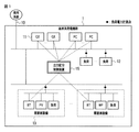
図1は、本発明の各実施形態に係る出力配分制御装置が適用される電力系統の構成の一例を示す図である。 FIG. 1 is a diagram illustrating an example of a configuration of a power system to which an output distribution control device according to each embodiment of the present invention is applied.
図1に示される電力系統1においては、電力会社が管理する商用系統10、系統全体の需給バランス維持に使用されるガスエンジン(GE)や燃料電池(FC)などの基幹系発電機群11、およびそれらの電力を使用する基幹系負荷群(学校、病院、工場など)12、ならびに、電気自動車やプラグイン・ハイブリッド自動車などに備えられる二次電池を電力貯蔵装置(BT)として活用する多数の需要家の設備群(一般家庭を含む)13が接続されている。需要家の設備群13は、それぞれ、二次電池である上記電力貯蔵装置(BT)のほかに、分散型電源を構成する太陽光発電(PV)や風力発電(WP)などの自然エネルギーを利用する電源、および負荷を含む。
In the
さらに、上記電力系統1には、出力配分制御装置15が備えられる。この出力配分制御装置15は、同系統内に電力貯蔵装置として導入されている多数の二次電池群に対し、同系統内に近接して設置された自然エネルギーを利用した分散型電源の出力変動を抑制するために、それら二次電池群の制御余力を確保するための制御を行いつつ、一方でそれら二次電池群の余剰能力を最大限に活用するために、同系統内における化石燃料等で運転される発電機の経済性を確保するための制御を行う。なお、基幹系負荷群12および需要家設備群13の負荷電力はそれぞれ図1中の負荷電力計測点にて計測器により計測され、計測結果が出力配分制御装置15に伝えられるようになっている。
Further, the
出力配分制御装置15の機能は、例えば図2に示されるような既知のプロセッサ101、メモリ102、入力装置103、表示装置104などの基本的なハードウェアを備えたコンピュータにより実行されるコンピュータプログラムとして構成することができる。この場合、プロセッサ101は、メモリ102を作業領域にしてコンピュータプログラムを実行することができる。また、入力装置103を通じてコンピュータプログラムや関連するデータに対する各種の設定を行ったり、表示装置104に各種の情報を表示させたりすることができる。
The function of the output
(第1の実施形態)
最初に、第1の実施形態について説明する。
図3は、本発明の第1の実施形態に係る出力配分制御装置の機能構成の一例を示す図である。
(First embodiment)
First, the first embodiment will be described.
FIG. 3 is a diagram illustrating an example of a functional configuration of the output distribution control apparatus according to the first embodiment of the present invention.
図3に示される出力配分制御装置15は、主な機能として、二次電池現在情報収集部201、負荷現在情報収集部202、基幹系発電機現在情報収集部203、仮想二次電池情報作成部204、予想総需要作成部205、基幹系発電機・仮想二次電池出力配分値計算部(第1の出力配分決定部)206、個別二次電池出力配分値計算部(第2の出力配分決定部)207、二次電池制御部208、および基幹系発電機制御部209を有する。
The output
図3中の二次電池群21は、図1中の需要家設備群13の電力貯蔵装置群(BT)に相当するものである。また、図3中の負荷群22は、図1中の基幹系負荷群12および需要家設備群13の負荷群に相当するものである。また、図3中の基幹系発電機群23は、図1中の基幹系発電機群11に相当するものである。
The
なお、二次電池現在情報収集部201は、二次電池群21に備えられていてもよい。また、負荷現在情報収集部202は、負荷群22に備えられていてもよい。また、基幹系発電機現在情報収集部203は、基幹系発電機群23に備えられていてもよい。
The secondary battery current
二次電池現在情報収集部201は、二次電池群21のそれぞれの現在の状態(現在の充放電出力もしくは蓄電量など)を示す個別二次電池情報D1を収集するものである。
The secondary battery current
負荷現在情報収集部202は、負荷群22のそれぞれの現在の状態(図1中の負荷電力計測点にて計測されるそれぞれの現在の負荷電力など)を示す負荷情報D2を収集するものである。
The load current
基幹系発電機現在情報収集部203は、基幹系発電機群23のそれぞれの現在の状態(現在の発電機出力など)を示す基幹系発電機現在情報D3を収集するものである。
The main generator current
仮想二次電池情報作成部204は、前記個別二次電池現在情報D1と、二次電池群21のそれぞれの設備仕様を示す個別二次電池設備情報D4と、二次電池群21のそれぞれについて各需要家が設定した運用上の制約(各二次電池の出力や容量について各需要家が設定した運用上の上下限値など)を示す個別二次電池設定値D5とに基づき、二次電池群21を1つの仮想的な二次電池とみなしたときの当該仮想二次電池の現在の状態や運用上の制約(仮想二次電池の現在の充放電出力もしくは蓄電量、出力や容量についての運用上の上下限値など)を示す仮想二次電池情報D6を作成するものである。なお、個別二次電池設備情報D4は、オフラインで予め登録され、また、個別二次電池設定値D5は、オフラインで予め設定される。
The virtual secondary battery
予想総需要作成部205は、前記負荷情報D2と、負荷群22のそれぞれの想定される需要の経時変化を示す想定需要カーブD7とに基づき、予想される総需要の経時変化を示す予想総需要カーブD8を作成するものである。
The predicted total
基幹系発電機・仮想二次電池出力配分値計算部206は、前記基幹系発電機現在情報D3と、前記仮想二次電池情報D6と、前記予想総需要カーブD8と、基幹系発電機群23のそれぞれの設備仕様を示す発電機設備情報D9とに基づき、基幹系発電機群23の出力配分値を示す基幹系発電機出力配分値(運転スケジュール)D10と、仮想二次電池の出力配分値を示す仮想二次電池出力配分値(運転スケジュール)D11とを決定する。特に、この基幹系発電機・仮想二次電池出力配分値計算部206は、各制約が存在する中で、基幹系発電機群23の燃料費が最小となるような、基幹系発電機群23の出力配分値と仮想二次電池の出力配分値とを決定する。例えば、この基幹系発電機・仮想二次電池出力配分値計算部206は、基幹系発電機群23の出力を変数として含む基幹系発電機群23の燃料費を表す関数を用いて、当該燃料費が最小となる基幹系発電機群23の出力を求め、求めた基幹系発電機群23の出力を負荷群22の需要から差し引くことによって仮想二次電池の出力を求める。
The main generator / virtual secondary battery output distribution
個別二次電池出力配分値計算部207は、前記個別二次電池現在情報D1と、個別二次電池設備情報D4と、個別二次電池設定値D5と、前記仮想二次電池出力配分値D11とに基づき、二次電池群21のそれぞれの出力配分値を示す個別二次電池出力配分値(運転スケジュール)D12を決定する。特に、この個別二次電池出力配分値計算部207は、各制約が存在する中で、二次電池群21の制御余力の合計が最大となるように、二次電池群21のそれぞれの出力配分を決定する。例えば、この個別二次電池出力配分値計算部207は、二次電池群21のそれぞれの蓄電量の上下限の中間値からの当該二次電池群21のそれぞれの蓄電量の偏差を表す関数を用いて、それぞれの偏差が最小となる二次電池群21のそれぞれの蓄電量を求め、求めた蓄電量の時間変位から二次電池群21のそれぞれの出力を決定する。
The individual secondary battery output distribution
二次電池制御部208は、前記個別二次電池出力配分値(運転スケジュール)D12に基づき、二次電池群21のそれぞれの出力を制御するものである。
The secondary
基幹系発電機制御部209は、前記基幹系発電機出力配分値D10に基づき、基幹系発電機群23のそれぞれの出力を制御するものである。
The backbone
次に、上記のように構成した出力配分制御装置15の動作について、図4に示すフローチャートを用いて説明する。
Next, the operation of the output
ステップS1では、二次電池現在情報収集部201が、二次電池群21のそれぞれの現在の状態(現在の充放電出力もしくは蓄電量など)を示す個別二次電池情報D1を収集する。
In step S <b> 1, the secondary battery current
ステップS2では、負荷現在情報収集部202が、負荷群22のそれぞれの現在の状態(図1中の負荷電力計測点にて計測されるそれぞれの現在の負荷電力など)を示す負荷情報D2を収集する。
In step S2, the load current
ステップS3では、基幹系発電機現在情報収集部203が、基幹系発電機群23のそれぞれの現在の状態(現在の発電機出力など)を示す基幹系発電機現在情報D3を収集する。
In step S <b> 3, the backbone generator current
ステップS4では、仮想二次電池情報作成部204が、個別二次電池現在情報D1と、個別二次電池設備情報D4と、個別二次電池設定値D5とに基づき、仮想二次電池情報D6を作成する。すなわち、N個の二次電池群21を1つの仮想二次電池とみなすため、N個の二次電池群21のそれぞれに関する情報の総和を、時刻(もしくは時間帯)t0,…,T毎に求める。具体的には、例えば以下の数式を用いる。

ここで、
なお、「個別二次電池運用上限出力」,「個別二次電池運用下限出力」は、各需要家が時間帯毎に設定した設定値である。「個別二次電池容量運用上限」,「個別二次電池容量運用下限」は、各需要家が自然エネルギーを利用した分散型電源の出力変動抑制のために、制御余力として確保するように時間帯毎に設定した上下限である。これらは、個別二次電池設定値D5から得ることができる。また、「個別二次電池上げ方向出力変化速度」,「個別二次電池下げ方向出力変化速度」は、個別二次電池設備情報D4から得ることができる。 The “individual secondary battery operation upper limit output” and “individual secondary battery operation lower limit output” are set values set by each consumer for each time zone. “Individual secondary battery capacity operation upper limit” and “Individual secondary battery capacity operation lower limit” are time zones to ensure that each consumer has enough control capacity to suppress fluctuations in output of distributed power sources using natural energy. Upper and lower limits set for each. These can be obtained from the individual secondary battery set value D5. Further, “individual secondary battery raising direction output change speed” and “individual secondary battery lowering direction output change speed” can be obtained from the individual secondary battery equipment information D4.
需要家が主体的にスケジュール運転を実施したい場合には、例えば以下の数式で表される制約を設定すればよい。
ステップS5では、予想総需要作成部205が、負荷情報D2と、想定需要カーブD7とに基づき、予想総需要カーブD8を作成する。具体的には、例えば以下の数式を用いる。
ステップS6では、基幹系発電機・仮想二次電池出力配分値計算部206が、基幹系発電機現在情報D3と、仮想二次電池情報D6と、予想総需要カーブD8と、発電機設備情報D9とに基づき、基幹系発電機出力配分値(運転スケジュール)D10と、仮想二次電池出力配分値(運転スケジュール)D11とを決定する。すなわち、各制約が存在する中で、基幹系発電機群23の燃料費が最小となるように、基幹系発電機群23の出力配分値と仮想二次電池の出力配分値とを決定する。具体的には、例えば以下のような手法を用いる。
In step S6, the backbone generator / virtual secondary battery output distribution
まず、動的計画法により、基幹系発電機群23の燃料費が最小となる、仮想二次電池の一定時間毎の蓄電量を計算する。
First, the amount of electricity stored in the virtual secondary battery at a certain time, at which the fuel cost of the
図5に示すように、現在時刻t0から仮想二次電池計算期間最終時刻Tまでの蓄電量について考える。なお、仮想二次電池計算期間最終時刻TおよびTにおける目標となる蓄電量VEは、例えば前日に立てた計画値または当日運用者が与えた蓄電目標量とする。ここで蓄電量を連続値として扱うと、現在蓄電量VSから目標となる蓄電量VEに至るまでには無数の経路が出現してしまうため、蓄電量を離散値化する。 As shown in FIG. 5, consider the storage amount from the current time t 0 to the virtual secondary battery calculation period final time T. Note that the target storage amount VE at the virtual secondary battery calculation period final times T and T is, for example, the planned value set on the previous day or the storage target amount given by the operator on the day. Here, if the stored amount is treated as a continuous value, an infinite number of paths appear from the current stored amount VS to the target stored amount VE, so the stored amount is converted to a discrete value.
例えば、時間tにおける蓄電量状態数(蓄電量VESが異なる個々の状態に離散化された数)をStとすると、時間t−1におけるS(t−1)個の蓄電量状態から、出力ES(充電または放電)により、時間tにおけるある蓄電量状態Aに至るまでには、S(t−1)個のパス(経路)が存在する。 For example, when the storage amount number of states at time t (number of charged amount VES is discretized into different individual states) and S t, from S (t-1) pieces of storage amount state at time t-1, the output There are S (t−1) paths (routes) by ES (charge or discharge) until reaching a certain charged amount state A at time t.
この場合、図6に示すように、時間帯t−1においてS(t−1)個に離散化された蓄電量VESは、S(t−1)個に離散化された燃料費C(VES)を生じさせる。また、時間帯t−1においてS(t−1)個に離散化された蓄電量VESに対する出力ES(充電または放電)は、S(t−1)個に離散化された燃料費C(ES)を生じさせる。 In this case, as shown in FIG. 6, the storage amount VES discretized into S (t−1) in the time zone t−1 is the fuel cost C (VES discretized into S (t−1). ). Further, the output ES (charge or discharge) with respect to the storage amount VES discretized into S (t−1) pieces in the time zone t−1 is the fuel cost C (ES ) discretized into S (t−1) pieces. ).
例えば、時間帯t−1における任意の蓄電量状態s(但し、1≦s≦S(t−1))の蓄電量VESt−1,sは、燃料費C(VESt−1,s)を生じさせる。また、当該蓄電量VESt−1,sに対する出力ESt,s(充電または放電)は、燃料費C(ESt−1,s)を生じさせる。 For example, the storage amount VES t−1, s in any storage state s (where 1 ≦ s ≦ S (t−1) ) in the time zone t−1 is the fuel cost C (VES t−1, s ). Give rise to Further, the output ES t, s (charging or discharging) with respect to the charged amount VES t-1, s causes a fuel cost C (ES t-1, s ).
ここで、S(t−1)個のパスの中から、C(VES)+C(ES)が最小となるパスを選択するための処理を行う。また、時間tにおける状態A以外の蓄電量状態に至るパスについても同様な処理を行う(すなわち、St個の各状態に至るパスの全てについて実施する)。さらには、時間t−1とtとの間のパス以外のパスについても同様な処理を行う(すなわち、時間t0〜Tの間に存在する全てのパスについて実施する)。具体的には、例えば以下の数式を用いる。
ここで、基幹系発電機群23の燃料費の最小とするようなESt,sは、例えば以下の非線形計画問題を解くことで求めることができる。一般には基幹系発電機燃料費特性は2次式で近似できる場合がほとんどであるため、2次計画問題として定式化することができる。2次計画問題は比較的高速に解けることが知られている。
Here, ES t, s that minimizes the fuel cost of the main
例えば、目的関数を「燃料費最小化」とする以下の式を用いる。
また、制約条件を「需給バランス制約」とする以下の式を用いる(但し、EStは所与とする)。
すなわち、基幹系発電機群23の出力GPk,tを変数として含む基幹系発電機群23の燃料費の特性を表す関数fkを用いて、当該燃料費が最小となる基幹系発電機群23の出力を求め、求めた基幹系発電機群23の出力を負荷群22の需要から差し引くことによって仮想二次電池の出力を求めることができる。
That is, by using the function f k representing the fuel cost characteristic of the
なお、上記「基幹系発電機上限出力」,「基幹系発電機下限出力」,「基幹系発電機上げ方向出力変化速度」,「基幹系発電機下げ方向出力変化速度」は、発電機設備情報D9から得ることができる。 Note that the “main system generator upper limit output”, “main system generator lower limit output”, “main system generator up direction output change speed”, and “main system generator down direction output change speed” are the generator facility information. Can be obtained from D9.
ステップS7では、個別二次電池出力配分値計算部207は、仮想二次電池出力配分値D11と、個別二次電池現在情報D1とに基づき、個別二次電池出力配分値D12を作成する。具体的には、例えば以下のような線形計画問題を解くことで個別二次電池出力配分値D12を求めることができる。このような線形計画問題は数万変数の問題でも高速に解けることが知られている。
In step S7, the individual secondary battery output distribution
例えば、目的関数を「制御余力最大化」(=蓄電量の中間値からの偏差最小化)とする以下の式を用いる。
すなわち、一般に二次電池の容量は有限であり、蓄電量が上限、或いは下限に達するとそれ以上の電力補償ができなくなるため、出力変動を補償する観点から、できるだけ蓄電量を中間値程度に保ち、常に制御余力を確保するようにしている。 That is, in general, the capacity of a secondary battery is finite, and if the amount of electricity stored reaches the upper limit or the lower limit, further power compensation cannot be performed. Therefore, from the viewpoint of compensating for output fluctuations, the amount of electricity stored should be kept at an intermediate value as much as possible. , Always trying to ensure control capacity.
上記計算結果から、各二次電池の出力配分値が以下のように求まる。
ステップS8では、二次電池制御部208が、ステップS7で求めた個別二次電池出力配分値D12に基づき、二次電池群21のそれぞれの制御を行う。
In step S8, the secondary
ステップS9では、基幹系発電機制御部209が、ステップS6で求めた基幹系発電機出力配分値D10に基づき、基幹系発電機群23のそれぞれの制御を行う。
In step S9, the backbone
この第1の実施形態によれば、出力配分制御装置が、電力系統内に電力貯蔵装置として導入されている多数の二次電池群に対し、同系統内に近接して設置された自然エネルギーを利用した分散型電源の出力変動を抑制するために、それら二次電池群の制御余力を確保するための制御を行いつつ、一方でそれら二次電池群の余剰能力を最大限に活用するために、同系統内における化石燃料等で運転される発電機の経済性を確保するための制御を行うので、経済性の確保と電力品質の確保の両方を実現することができる。また、二次電池の最適な運転スケジュールの作成・計算のためには、一般に、多数の非線形計画問題を解かねばならず、計算負荷が高いが、本実施形態では、個別の二次電池について計算を実施する前に、集約した仮想的な二次電池について計算を実施することで、計算負荷を低減させることができ、計算の高速性を実現することができる。 According to the first embodiment, the output distribution control device supplies natural energy installed in the vicinity of a large number of secondary battery groups introduced as power storage devices in the power system. In order to control the output fluctuations of the distributed power source used, while performing control to ensure the control capacity of those secondary battery groups, on the other hand, to make the most of the surplus capacity of these secondary battery groups Since the control for ensuring the economic efficiency of the generator operated with fossil fuel or the like in the same system is performed, both the economic efficiency and the electric power quality can be ensured. In addition, in order to create and calculate the optimum operation schedule of the secondary battery, generally, a large number of nonlinear programming problems must be solved, and the calculation load is high. In this embodiment, for the individual secondary battery, By performing the calculation for the aggregated virtual secondary battery before performing the calculation, the calculation load can be reduced, and the calculation speed can be increased.
(第2の実施形態)
次に、第2の実施形態について説明する。
なお、この第2の実施形態においては、第1の実施形態の構成と共通する部分には同一の符号を付し、重複する説明を省略する。以下では、第1の実施形態と異なる部分を中心に説明する。
(Second Embodiment)
Next, a second embodiment will be described.
In the second embodiment, parts that are the same as those in the first embodiment are given the same reference numerals, and redundant descriptions are omitted. Below, it demonstrates centering on a different part from 1st Embodiment.
図7は、本発明の第2の実施形態に係る出力配分制御装置の機能構成の一例を示す図である。 FIG. 7 is a diagram illustrating an example of a functional configuration of the output distribution control apparatus according to the second embodiment of the present invention.
第2の実施形態の出力配分制御装置15(図7)が、第1の実施形態の出力配分制御装置15(図3)と異なる点は、個別二次電池出力配分値計算部207が、個別二次電池出力配分値を計算するに際し、目的関数を「制御余力最大化」(=蓄電量の中間値からの偏差最小化)とする式を用いる代わりに、目的関数を「送電損失電力最小化」とする式を用いる点と、その計算のために系統接続・インピーダンス情報D101および前述の負荷情報D2(現在の負荷電力など)をさらに取得する点にある。系統接続・インピーダンス情報D101は、電力系統1を構成するノードおよびブランチの接続関係や各部のインピーダンス(もしくは抵抗)を示す情報である。これらの情報を利用することにより、個別二次電池出力配分値計算部207は、各制約が存在する中で、電力系統内のそれぞれのブランチ潮流やブランチ抵抗を変数として含む当該電力系統の送電損失を表す関数を用いて当該送電損失が最小となるそれぞれの潮流を求め、求めたそれぞれの潮流から二次電池群21のそれぞれの出力を決定する。
The difference between the output distribution control device 15 (FIG. 7) of the second embodiment and the output distribution control device 15 (FIG. 3) of the first embodiment is that the individual secondary battery output distribution
次に、上記のように構成した出力配分制御装置15の動作について、図8に示すフローチャートを用いて説明する。
Next, the operation of the output
ステップS1〜S6の処理については、図4のフローチャートで説明した通りであるため、その説明を省略する。 The processing in steps S1 to S6 is as described in the flowchart of FIG.
ステップS101では、個別二次電池出力配分値計算部207が、ステップS2で求めた負荷情報D2(現在の負荷電力など)と、系統接続・インピーダンス情報D101とを取得する。これらの情報は、後述するブランチ潮流の計算や送電損失の算定を行うために使用される。
In step S101, the individual secondary battery output distribution
ところで、直流法による潮流計算では、下記のようにブランチ潮流をノード注入電力(但し、発電はプラス、負荷はマイナスとする)の一次式で表現する方法がある。
ここで、行列Pは、個々のノードへのノード注入電力を表し、行列Aは、個々のノードにおける個々のブランチ潮流を表している。また、iは、m個のブランチのうちの任意のブランチを表し、jは、n個のノードのうちの任意のノードを表している。 Here, the matrix P represents node injection power to individual nodes, and the matrix A represents individual branch flows at individual nodes. Further, i represents an arbitrary branch among the m branches, and j represents an arbitrary node among the n nodes.
行列Aの成分は潮流分流係数と呼ばれるものである。潮流分流係数は、図9に示されるように、任意のノードjに電力Pjを1PU注入し、スイングノード(基準ノード)に逃がした場合に、任意のブランチiに流れるブランチ潮流Fiを表している。したがって、直流法による潮流計算を、ノード数分実行すれば、潮流分流係数を求めるこことができる。すなわち、1ノード分計算すれば行列Aの1列分が求まるので、これをノード数分実行する。 The component of the matrix A is called a tidal current diversion coefficient. As shown in FIG. 9, the tidal current diversion coefficient represents a branch tidal current F i flowing to an arbitrary branch i when 1 PU of electric power P j is injected into an arbitrary node j and released to a swing node (reference node). ing. Therefore, if the tidal current calculation by the direct current method is executed for the number of nodes, the tidal current diversion coefficient can be obtained. That is, if one node is calculated, one column of the matrix A is obtained, and this is executed for the number of nodes.
このようなブランチ潮流を用いた送電損失電力は、近似的に以下の式で表されることが知られている。
ここで、Fkは、任意のブランチkに流れるブランチ潮流を表し、rkは、ブランチの抵抗を表している。 Here, F k represents a branch tide flowing in any branch k, r k represents the resistance of the branch.
ステップS102では、個別二次電池出力配分値計算部207は、ステップS6で求めた仮想二次電池出力配分値D11と、ステップS1で求めた個別二次電池現在情報D1と、ステップS101で取得した負荷情報D2および系統接続・インピーダンス情報D101とに基づき、個別二次電池出力配分値D12を作成する。具体的には、例えば以下のような最適化問題を解くことで個別二次電池出力配分値D12を求めることができる。このような問題は2次計画問題であるため、実用的な時間で計算することが可能である。
In step S102, the individual secondary battery output distribution
例えば、目的関数を「送電損失電力最小化」とする以下の式を用いる。
また、制約条件については、以下の式を用いる。
すなわち、電力系統内のそれぞれのブランチ潮流Fkやブランチ抵抗rkを変数として含む当該電力系統の送電損失を表す関数を用いて、当該送電損失が最小となるそれぞれの潮流Fk,tを求め、求めたそれぞれの潮流を生じさせるノード注入電力BTi,tを、二次電池群21のそれぞれの出力とする。
In other words, calculated using a function representing the transmission loss of the electric power system with each branch power flow F k and branch resistors r k of the power in the system as variables, each of the power flow F k to the transmission loss is minimized, the t The node injection powers BT i, t that generate the respective power flows are used as the outputs of the
ステップS8〜S9の処理については、図4のフローチャートで説明した通りであるため、その説明を省略する。 The processing in steps S8 to S9 is as described in the flowchart of FIG.
この第2の実施形態によれば、個別二次電池出力配分値計算において、時々刻々と変化する負荷状況に合わせて送電損失を最小にする手法を適用することにより、前述の第1の実施形態と同様の効果を得ることができる。 According to the second embodiment, in the calculation of the distribution value of the individual secondary battery output, by applying the technique for minimizing the transmission loss according to the load situation that changes from moment to moment, the first embodiment described above is applied. The same effect can be obtained.
(第3の実施形態)
次に、第3の実施形態について説明する。
なお、この第3の実施形態においては、第2の実施形態の構成と共通する部分には同一の符号を付し、重複する説明を省略する。以下では、第2の実施形態と異なる部分を中心に説明する。
(Third embodiment)
Next, a third embodiment will be described.
In the third embodiment, parts that are the same as those in the configuration of the second embodiment are given the same reference numerals, and redundant descriptions are omitted. Below, it demonstrates centering on a different part from 2nd Embodiment.
第3実施形態に係る出力配分制御装置の機能構成は、図7に示した構成と同じである。 The functional configuration of the output distribution control apparatus according to the third embodiment is the same as the configuration shown in FIG.
但し、個別二次電池出力配分値計算部207は、個別二次電池出力配分値を計算するに際し、目的関数を「送電損失電力最小化」とする式、または、目的関数を「制御余力最大化」(=蓄電量の中間値からの偏差最小化)とする式を用いる。また、制約条件としては、前述の第2の実施形態で説明したものを用いることに加え、電力系統内のそれぞれの潮流の上下限を示す潮流制約を用いる。すなわち、個別二次電池出力配分値計算部207は、電力系統内のそれぞれの潮流の上下限を示す潮流制約が存在する中で、二次電池群21のそれぞれの出力を決定する機能を有する。
However, when calculating the individual secondary battery output distribution value, the individual secondary battery output distribution
次に、上記のように構成した出力配分制御装置15の動作について、図10に示すフローチャートを用いて説明する。
Next, the operation of the output
ステップS1〜S6およびS101の処理については、図8のフローチャートで説明した通りであるため、その説明を省略する。 The processing in steps S1 to S6 and S101 is as described in the flowchart of FIG.
ステップS201では、個別二次電池出力配分値計算部207は、個別二次電池出力配分値D12を作成するに際し、具体的には、例えば以下のような最適化問題を解くことで個別二次電池出力配分値D12を求める。
In step S201, the individual secondary battery output distribution
例えば、目的関数を「送電損失電力最小化」とする以下の式、または、目的関数を「制御余力最大化」(=蓄電量の中間値からの偏差最小化)とする以下の式を用いる。このような問題は2次計画問題であるため、実用的な時間で計算することが可能である。
また、制約条件については、以下の式を用いる。
すなわち、ステップS201では、個別二次電池出力配分値計算部207が、電力系統内のそれぞれの潮流Fi,tの上下限を示す潮流制約が存在する中で、電力系統の送電損失が最小となるそれぞれの潮流、または、二次電池群21の制御余力が最大となるそれぞれの潮流を求め、求めたそれぞれの潮流から二次電池群21のそれぞれの出力を決定する。
That is, in step S201, the individual secondary battery output distribution
ステップS8〜S9の処理については、図8のフローチャートで説明した通りであるため、その説明を省略する。 The processing in steps S8 to S9 is as described in the flowchart of FIG.
この第3の実施形態によれば、潮流制約が存在する中で個別二次電池出力配分値計算を行うことにより、電力品質の確保をより一層確実なものとすることができる。 According to the third embodiment, it is possible to further ensure the power quality by performing the individual secondary battery output distribution value calculation in the presence of the power flow restriction.
上述した各実施形態で述べた各種の機能や処理手順は、コンピュータプログラムとして、コンピュータにより読み取り可能な記憶媒体(例えば磁気ディスク,光ディスク,半導体メモリ)に記憶させておき、必要に応じてそれをプロセッサにより読み出して実行するようにしてもよい。また、このようなコンピュータプログラムは、通信媒体を介してあるコンピュータから他のコンピュータに伝送することにより配布することも可能である。 The various functions and processing procedures described in each embodiment described above are stored as a computer program in a computer-readable storage medium (for example, a magnetic disk, an optical disk, and a semiconductor memory), and the processor and processor are used as necessary. May be read out and executed. Such a computer program can also be distributed by transmitting from one computer to another computer via a communication medium.
本発明は上記実施形態そのままに限定されるものではなく、実施段階ではその要旨を逸脱しない範囲で構成要素を変形して具体化できる。また、上記実施形態に開示されている複数の構成要素の適宜な組み合わせにより、種々の発明を形成できる。例えば、実施形態に示される全構成要素から幾つかの構成要素を削除してもよい。さらに、異なる実施形態にわたる構成要素を適宜組み合わせてもよい。 The present invention is not limited to the above-described embodiments as they are, and can be embodied by modifying the constituent elements without departing from the scope of the invention in the implementation stage. In addition, various inventions can be formed by appropriately combining a plurality of components disclosed in the embodiment. For example, some components may be deleted from all the components shown in the embodiment. Furthermore, constituent elements over different embodiments may be appropriately combined.
1…電力系統、10…商用系統、11…基幹系発電機群、12…基幹系負荷群、13…需要家設備群、15…出力配分制御装置、21…二次電池群、22…負荷群、23…基幹系発電機群、101…プロセッサ、102…メモリ、103…入力装置、104…表示装置、201…二次電池現在情報収集部、202…負荷現在情報収集部、203…基幹系発電機現在情報収集部、204…仮想二次電池情報作成部、205…予想総需要作成部、206…基幹系発電機・仮想二次電池出力配分値計算部(第1の出力配分決定部)、207…個別二次電池出力配分値計算部(第2の出力配分決定部)、208…二次電池制御部、209…基幹系発電機制御部。
DESCRIPTION OF
Claims (6)
少なくとも前記負荷群の需要を示す情報と、前記発電機群の出力および運用上の制約を示す情報と、前記二次電池群の蓄電量および運用上の制約を示す情報とに基づき、各制約が存在する中で、前記発電機群の燃料費が最小となるように、前記発電機群の出力配分と、前記二次電池群を1つの仮想的な二次電池とみなしたときの当該仮想二次電池の出力配分とを決定する第1の出力配分決定手段と、
少なくとも前記第1の出力配分決定手段により決定された仮想二次電池の出力配分と、前記二次電池群の蓄電量および運用上の制約を示す情報とに基づき、各制約が存在する中で、前記二次電池群の制御余力の合計が最大となるように、或いは当該電力系統の送電損失が最小となるように、前記二次電池群のそれぞれの出力配分を決定する第2の出力配分決定手段と
を具備することを特徴とする出力配分制御装置。 An output distribution control device applied to a power system to which a generator group, a load group, and a secondary battery group are connected,
Each constraint is based on at least information indicating the demand of the load group, information indicating the output and operational constraints of the generator group, and information indicating the storage amount of the secondary battery group and operational constraints. In order to minimize the fuel cost of the generator group, the output distribution of the generator group and the virtual secondary battery when the secondary battery group is regarded as one virtual secondary battery. First output distribution determining means for determining output distribution of the secondary battery;
Based on at least the output distribution of the virtual secondary battery determined by the first output distribution determination means and the information indicating the storage amount and operational restrictions of the secondary battery group, each constraint exists, Second output distribution determination for determining the respective output distribution of the secondary battery group so that the total control margin of the secondary battery group is maximized or the transmission loss of the power system is minimized. And an output distribution control device.
第1の出力配分決定手段が、少なくとも前記負荷群の需要を示す情報と、前記発電機群の出力および運用上の制約を示す情報と、前記二次電池群の蓄電量および運用上の制約を示す情報とに基づき、各制約が存在する中で、前記発電機群の燃料費が最小となるように、前記発電機群の出力配分と、前記二次電池群を1つの仮想的な二次電池とみなしたときの当該仮想二次電池の出力配分とを決定し、
第2の出力配分決定手段が、少なくとも前記第1の出力配分決定手段により決定された仮想二次電池の出力配分と、前記二次電池群の蓄電量および運用上の制約を示す情報とに基づき、各制約が存在する中で、前記二次電池群のそれぞれの制御余力の合計が最大となるように、或いは当該電力系統での送電損失が最小となるように、前記二次電池群のそれぞれの出力配分を決定する
ことを特徴とする出力配分制御方法。 An output distribution control method applied to a power system to which a generator group, a load group, and a secondary battery group are connected,
The first output distribution determining means includes at least information indicating the demand of the load group, information indicating the output of the generator group and operational restrictions, and the storage amount and operational restrictions of the secondary battery group. Based on the information shown, the output distribution of the generator group and the secondary battery group are combined into one virtual secondary so that the fuel cost of the generator group is minimized while each constraint exists. Determine the output distribution of the virtual secondary battery when considered as a battery,
The second output distribution determination means is based on at least the output distribution of the virtual secondary battery determined by the first output distribution determination means, and the information indicating the storage amount of the secondary battery group and operational restrictions. In the presence of each constraint, each of the secondary battery groups so that the total control power of each of the secondary battery groups is maximized or the transmission loss in the power system is minimized. An output distribution control method characterized by determining an output distribution of the output.
Priority Applications (5)
| Application Number | Priority Date | Filing Date | Title |
|---|---|---|---|
| JP2010172756A JP5481305B2 (en) | 2010-07-30 | 2010-07-30 | Output distribution controller |
| PCT/JP2010/065470 WO2012014332A1 (en) | 2010-07-30 | 2010-09-09 | Output distribution control apparatus |
| EP10855339.7A EP2600482A4 (en) | 2010-07-30 | 2010-09-09 | Output distribution control apparatus |
| CN201080066732.0A CN102893481B (en) | 2010-07-30 | 2010-09-09 | Output distribution control apparatus |
| US13/751,944 US20130140889A1 (en) | 2010-07-30 | 2013-01-28 | Output distribution control apparatus |
Applications Claiming Priority (1)
| Application Number | Priority Date | Filing Date | Title |
|---|---|---|---|
| JP2010172756A JP5481305B2 (en) | 2010-07-30 | 2010-07-30 | Output distribution controller |
Publications (2)
| Publication Number | Publication Date |
|---|---|
| JP2012034514A JP2012034514A (en) | 2012-02-16 |
| JP5481305B2 true JP5481305B2 (en) | 2014-04-23 |
Family
ID=45529574
Family Applications (1)
| Application Number | Title | Priority Date | Filing Date |
|---|---|---|---|
| JP2010172756A Expired - Fee Related JP5481305B2 (en) | 2010-07-30 | 2010-07-30 | Output distribution controller |
Country Status (5)
| Country | Link |
|---|---|
| US (1) | US20130140889A1 (en) |
| EP (1) | EP2600482A4 (en) |
| JP (1) | JP5481305B2 (en) |
| CN (1) | CN102893481B (en) |
| WO (1) | WO2012014332A1 (en) |
Families Citing this family (13)
| Publication number | Priority date | Publication date | Assignee | Title |
|---|---|---|---|---|
| JP5504504B2 (en) * | 2010-09-24 | 2014-05-28 | 独立行政法人情報通信研究機構 | System for performing arithmetic processing related to resource allocation and method for determining resource allocation |
| JP6088737B2 (en) * | 2012-02-16 | 2017-03-01 | 株式会社日立製作所 | Power system operation method, operation device, and storage battery management device |
| JP2014023232A (en) * | 2012-07-17 | 2014-02-03 | Toshiba Corp | Energy management device, energy management method, and energy management program |
| ITPD20130303A1 (en) * | 2013-11-11 | 2015-05-12 | Elettrograf S R L | DEVICE FOR THE MANAGEMENT AND OPTIMIZATION OF ELECTRICITY CONSUMPTION FROM MEANS OF ENERGY SUPPLIERS IN A CONTINUOUS CURRENT AND IN PARTICULAR FROM RENEWABLE SOURCES GENERATORS |
| JP2015186361A (en) * | 2014-03-25 | 2015-10-22 | 株式会社日立製作所 | Power adjustment controller and power adjustment control method |
| JP2016042748A (en) * | 2014-08-14 | 2016-03-31 | 株式会社Ihi | Energy management system and power demand plan optimization method |
| JP2016220396A (en) * | 2015-05-20 | 2016-12-22 | パナソニックIpマネジメント株式会社 | Distributed power supply system and distributed power supply system control method |
| JP6210419B2 (en) * | 2015-06-09 | 2017-10-11 | パナソニックIpマネジメント株式会社 | Power control method and power control apparatus |
| JP6789866B2 (en) * | 2017-03-28 | 2020-11-25 | 京セラ株式会社 | Power storage device and power management system |
| CZ308496B6 (en) * | 2020-01-27 | 2020-09-23 | Vysoká Škola Báňská - Technická Univerzita Ostrava | Control system of an AC charging station or group of charging stations for local distribution networks with limited reserve capacity and method of control using this system |
| CN111367169A (en) * | 2020-02-07 | 2020-07-03 | 大连富士冰山智控系统有限公司 | Control system, control device, and control method |
| JP2023163578A (en) * | 2022-04-28 | 2023-11-10 | 株式会社日立製作所 | Virtual power storage management system, and virtual power storage management method |
| JP2024008336A (en) * | 2022-07-08 | 2024-01-19 | 株式会社日立製作所 | Information processing apparatus |
Family Cites Families (24)
| Publication number | Priority date | Publication date | Assignee | Title |
|---|---|---|---|---|
| JP2979939B2 (en) * | 1993-12-27 | 1999-11-22 | 株式会社日立製作所 | Operation method of secondary battery system |
| JPH11196530A (en) * | 1997-12-26 | 1999-07-21 | Hitachi Ltd | Generator load distributing device |
| EP1262008B1 (en) * | 2000-01-28 | 2009-09-09 | Cummins Generator Technologies Limited | Ac power generating system |
| JP3801910B2 (en) * | 2001-11-27 | 2006-07-26 | 日本電信電話株式会社 | Fuel cell system control method |
| JP3753113B2 (en) * | 2002-08-23 | 2006-03-08 | 三菱電機株式会社 | Generator control device |
| JP4445361B2 (en) * | 2004-09-24 | 2010-04-07 | 関西電力株式会社 | Power system control method and power system control apparatus using secondary battery |
| JP4192131B2 (en) | 2004-09-24 | 2008-12-03 | 関西電力株式会社 | Power generation planning method and power generation planning apparatus using secondary battery |
| US7274975B2 (en) * | 2005-06-06 | 2007-09-25 | Gridpoint, Inc. | Optimized energy management system |
| JP4327143B2 (en) * | 2005-09-30 | 2009-09-09 | パナソニックEvエナジー株式会社 | Secondary battery control device, secondary battery output control method, and secondary battery output control execution program |
| JP4518002B2 (en) | 2005-11-01 | 2010-08-04 | 富士電機システムズ株式会社 | Power stabilization system using power storage device and control device thereof |
| JP4432938B2 (en) | 2006-06-07 | 2010-03-17 | 富士電機システムズ株式会社 | Power stabilization system using power storage device and control device thereof |
| JP4487989B2 (en) * | 2006-08-04 | 2010-06-23 | トヨタ自動車株式会社 | Power system and method for managing state of charge in power system |
| JP2008067418A (en) | 2006-09-04 | 2008-03-21 | Nippon Telegr & Teleph Corp <Ntt> | Charging control method, electricity accumulator and charging control system |
| JP4203602B2 (en) * | 2006-09-06 | 2009-01-07 | 国立大学法人 琉球大学 | Operation support method and apparatus for power supply equipment |
| JP4783246B2 (en) * | 2006-09-06 | 2011-09-28 | 関西電力株式会社 | Power system control device and method using secondary battery, power generation planning device, real-time control device, and power system control system |
| JP2008141026A (en) | 2006-12-04 | 2008-06-19 | Sony Corp | Electronic instrument, its manufacturing method, light emitting diode display device and its manufacturing method |
| US7991512B2 (en) * | 2007-08-28 | 2011-08-02 | General Electric Company | Hybrid robust predictive optimization method of power system dispatch |
| JP5011230B2 (en) * | 2008-08-04 | 2012-08-29 | 株式会社東芝 | Secondary battery control device and control method |
| CN101667735B (en) * | 2008-09-02 | 2014-04-23 | 日本碍子株式会社 | Method for controlling electric power of secondary batteries |
| EP2330678B1 (en) * | 2008-09-30 | 2017-11-01 | NGK Insulators, Ltd. | Secondary battery power control method |
| JP2010098793A (en) * | 2008-10-14 | 2010-04-30 | Osaka Gas Co Ltd | Power demand and supply system |
| DE102009018240A1 (en) * | 2009-04-21 | 2010-11-04 | Adensis Gmbh | Photovoltaic system with battery and backup power plant |
| US8072092B2 (en) * | 2009-07-24 | 2011-12-06 | C.E. Niehoff & Co. | System and method for sequentional electrical power delivery from two generators in a vehicle electrical system |
| US8937405B2 (en) * | 2009-12-31 | 2015-01-20 | Facebook, Inc. | Data center using fuel cells in place of diesel generators for backup power |
-
2010
- 2010-07-30 JP JP2010172756A patent/JP5481305B2/en not_active Expired - Fee Related
- 2010-09-09 EP EP10855339.7A patent/EP2600482A4/en not_active Withdrawn
- 2010-09-09 WO PCT/JP2010/065470 patent/WO2012014332A1/en active Application Filing
- 2010-09-09 CN CN201080066732.0A patent/CN102893481B/en not_active Expired - Fee Related
-
2013
- 2013-01-28 US US13/751,944 patent/US20130140889A1/en not_active Abandoned
Also Published As
| Publication number | Publication date |
|---|---|
| CN102893481A (en) | 2013-01-23 |
| EP2600482A4 (en) | 2016-01-13 |
| CN102893481B (en) | 2014-12-31 |
| US20130140889A1 (en) | 2013-06-06 |
| WO2012014332A1 (en) | 2012-02-02 |
| EP2600482A1 (en) | 2013-06-05 |
| JP2012034514A (en) | 2012-02-16 |
Similar Documents
| Publication | Publication Date | Title |
|---|---|---|
| JP5481305B2 (en) | Output distribution controller | |
| Emad et al. | Computational methods for optimal planning of hybrid renewable microgrids: a comprehensive review and challenges | |
| Wang et al. | Optimal siting and sizing of soft open points in active electrical distribution networks | |
| Zahboune et al. | Optimal hybrid renewable energy design in autonomous system using Modified Electric System Cascade Analysis and Homer software | |
| Mohamed et al. | Sizing and techno-economic analysis of stand-alone hybrid photovoltaic/wind/diesel/battery power generation systems | |
| Torreglosa et al. | Control based on techno-economic optimization of renewable hybrid energy system for stand-alone applications | |
| Dufo-Lopez et al. | Multi-objective design of PV–wind–diesel–hydrogen–battery systems | |
| Kusakana et al. | Hybrid diesel generator/renewable energy system performance modeling | |
| Panahandeh et al. | Simulation of PV–Wind-hybrid systems combined with hydrogen storage for rural electrification | |
| Khatib et al. | Novel simplified hourly energy flow models for photovoltaic power systems | |
| Hooshmand et al. | Experimental demonstration of a tiered power management system for economic operation of grid-tied microgrids | |
| Ersal et al. | Impact of controlled plug-in EVs on microgrids: A military microgrid example | |
| Koubaa et al. | Robust optimization based energy management of a fuel cell/ultra-capacitor hybrid electric vehicle under uncertainty | |
| JP5520256B2 (en) | MICROGRID, ITS CONTROL DEVICE, AND ITS CONTROL METHOD | |
| JP2013013240A (en) | Device and method for creating demand and supply plan of storage battery | |
| Mohammad-Alikhani et al. | Multiobjective optimization of system configuration and component capacity in an AC minigrid hybrid power system | |
| Raducu et al. | Design and implementation of a hybrid power plant controller | |
| Rampazzo et al. | Modelling and simulation of a Li-ion energy storage system: Case study from the island of Ventotene in the Tyrrhenian Sea | |
| Katsigiannis et al. | Genetic algorithm solution to optimal sizing problem of small autonomous hybrid power systems | |
| JP2018014775A (en) | Integrated controller, integrated control system, integrated control method and integrated control program | |
| Vafaei | Optimally-sized design of a wind/diesel/fuel cell hybrid system for a remote community | |
| KR101707013B1 (en) | Reactive power control apparatus and method of combined generation system | |
| Kumar et al. | Energy management strategy using model predictive control for power-to-gas (PtG) system integrated with microgrid | |
| Gong et al. | Economic dispatching strategy of double lead-acid battery packs considering various factors | |
| Uddin et al. | Modeling of campus microgrid for off-grid application |
Legal Events
| Date | Code | Title | Description |
|---|---|---|---|
| A621 | Written request for application examination |
Free format text: JAPANESE INTERMEDIATE CODE: A621 Effective date: 20130227 |
|
| RD04 | Notification of resignation of power of attorney |
Free format text: JAPANESE INTERMEDIATE CODE: A7424 Effective date: 20131205 |
|
| RD04 | Notification of resignation of power of attorney |
Free format text: JAPANESE INTERMEDIATE CODE: A7424 Effective date: 20131212 |
|
| RD04 | Notification of resignation of power of attorney |
Free format text: JAPANESE INTERMEDIATE CODE: A7424 Effective date: 20131219 |
|
| RD04 | Notification of resignation of power of attorney |
Free format text: JAPANESE INTERMEDIATE CODE: A7424 Effective date: 20131226 |
|
| RD04 | Notification of resignation of power of attorney |
Free format text: JAPANESE INTERMEDIATE CODE: A7424 Effective date: 20140109 |
|
| TRDD | Decision of grant or rejection written | ||
| RD04 | Notification of resignation of power of attorney |
Free format text: JAPANESE INTERMEDIATE CODE: A7424 Effective date: 20140116 |
|
| A01 | Written decision to grant a patent or to grant a registration (utility model) |
Free format text: JAPANESE INTERMEDIATE CODE: A01 Effective date: 20140121 |
|
| A61 | First payment of annual fees (during grant procedure) |
Free format text: JAPANESE INTERMEDIATE CODE: A61 Effective date: 20140217 |
|
| LAPS | Cancellation because of no payment of annual fees |