JP5402471B2 - Power supply, power cable, and receiver - Google Patents
Power supply, power cable, and receiver Download PDFInfo
- Publication number
- JP5402471B2 JP5402471B2 JP2009223406A JP2009223406A JP5402471B2 JP 5402471 B2 JP5402471 B2 JP 5402471B2 JP 2009223406 A JP2009223406 A JP 2009223406A JP 2009223406 A JP2009223406 A JP 2009223406A JP 5402471 B2 JP5402471 B2 JP 5402471B2
- Authority
- JP
- Japan
- Prior art keywords
- cable
- power
- power supply
- unit
- antenna
- Prior art date
- Legal status (The legal status is an assumption and is not a legal conclusion. Google has not performed a legal analysis and makes no representation as to the accuracy of the status listed.)
- Expired - Fee Related
Links
Images


Classifications
-
- H—ELECTRICITY
- H01—ELECTRIC ELEMENTS
- H01Q—ANTENNAS, i.e. RADIO AERIALS
- H01Q1/00—Details of, or arrangements associated with, antennas
- H01Q1/44—Details of, or arrangements associated with, antennas using equipment having another main function to serve additionally as an antenna, e.g. means for giving an antenna an aesthetic aspect
- H01Q1/46—Electric supply lines or communication lines
-
- H—ELECTRICITY
- H01—ELECTRIC ELEMENTS
- H01Q—ANTENNAS, i.e. RADIO AERIALS
- H01Q1/00—Details of, or arrangements associated with, antennas
- H01Q1/12—Supports; Mounting means
- H01Q1/22—Supports; Mounting means by structural association with other equipment or articles
- H01Q1/24—Supports; Mounting means by structural association with other equipment or articles with receiving set
- H01Q1/241—Supports; Mounting means by structural association with other equipment or articles with receiving set used in mobile communications, e.g. GSM
- H01Q1/242—Supports; Mounting means by structural association with other equipment or articles with receiving set used in mobile communications, e.g. GSM specially adapted for hand-held use
-
- H—ELECTRICITY
- H01—ELECTRIC ELEMENTS
- H01Q—ANTENNAS, i.e. RADIO AERIALS
- H01Q1/00—Details of, or arrangements associated with, antennas
- H01Q1/40—Radiating elements coated with or embedded in protective material
-
- H—ELECTRICITY
- H01—ELECTRIC ELEMENTS
- H01Q—ANTENNAS, i.e. RADIO AERIALS
- H01Q21/00—Antenna arrays or systems
- H01Q21/30—Combinations of separate antenna units operating in different wavebands and connected to a common feeder system
-
- H—ELECTRICITY
- H01—ELECTRIC ELEMENTS
- H01Q—ANTENNAS, i.e. RADIO AERIALS
- H01Q5/00—Arrangements for simultaneous operation of antennas on two or more different wavebands, e.g. dual-band or multi-band arrangements
-
- H—ELECTRICITY
- H01—ELECTRIC ELEMENTS
- H01Q—ANTENNAS, i.e. RADIO AERIALS
- H01Q5/00—Arrangements for simultaneous operation of antennas on two or more different wavebands, e.g. dual-band or multi-band arrangements
- H01Q5/30—Arrangements for providing operation on different wavebands
- H01Q5/307—Individual or coupled radiating elements, each element being fed in an unspecified way
- H01Q5/314—Individual or coupled radiating elements, each element being fed in an unspecified way using frequency dependent circuits or components, e.g. trap circuits or capacitors
- H01Q5/321—Individual or coupled radiating elements, each element being fed in an unspecified way using frequency dependent circuits or components, e.g. trap circuits or capacitors within a radiating element or between connected radiating elements
-
- H—ELECTRICITY
- H04—ELECTRIC COMMUNICATION TECHNIQUE
- H04M—TELEPHONIC COMMUNICATION
- H04M19/00—Current supply arrangements for telephone systems
- H04M19/08—Current supply arrangements for telephone systems with current supply sources at the substations
Landscapes
- Engineering & Computer Science (AREA)
- Computer Networks & Wireless Communication (AREA)
- Signal Processing (AREA)
- Details Of Aerials (AREA)
- Input Circuits Of Receivers And Coupling Of Receivers And Audio Equipment (AREA)
- Emergency Protection Circuit Devices (AREA)
Description
本発明は、放送波を受信可能な携帯電話やテレビジョン受像機等の電子機器に適用可能な電源装置、電源ケーブル、および受信装置に関するものである。 The present invention relates to a power supply device, a power cable, and a receiving device that can be applied to an electronic device such as a mobile phone or a television receiver capable of receiving broadcast waves.
一般的に、デジタルテレビジョン放送等を受信可能な携帯電話は、内蔵アンテナまたは外部アンテナで放送波を受信している。
内蔵アンテナは、携帯電話のデザインを損なわない長所がある。しかしながら、内蔵アンテナは、外部アンテナに比して感度が劣り、内部ノイズの影響を受け易い等の欠点がある。
In general, a mobile phone capable of receiving digital television broadcasts or the like receives broadcast waves with a built-in antenna or an external antenna.
The built-in antenna has the advantage that the design of the mobile phone is not impaired. However, the built-in antenna has disadvantages such as inferior sensitivity to an external antenna and being easily affected by internal noise.
これに対して外部アンテナには、たとえばロッドアンテナがある。
ロッドアンテナは、内蔵アンテナに比して感度等が優れる特徴がある。しかしながら、ロッドアンテナは、携帯電話のデザインを損ない、さらにはアンテナが突出する等の欠点がある。
On the other hand, an external antenna includes, for example, a rod antenna.
The rod antenna is characterized by excellent sensitivity and the like compared to the built-in antenna. However, the rod antenna has a drawback that the design of the mobile phone is damaged and the antenna protrudes.
この外部アンテナに関して、特許文献1,2等に、電源ケーブル(電源コード)をアンテナとして使用することが提案されている。
With respect to this external antenna,
テレビジョン受像機は、商用電源により動作し、屋外アンテナを介して放送波を受信する。
したがって、テレビジョン受像機は、背面から延長する電源ケーブルを家庭内のコンセントに接続して商用電源を入力する。またテレビジョン受像機は、背面にアンテナ用コネクタが設けられ、このアンテナ用コネクタを同軸ケーブルで屋外アンテナに接続して放送波を受信する。
なおテレビジョン受像機には、ロッドアンテナによる受信用アンテナが設けられるものもある。
The television receiver operates from a commercial power source and receives broadcast waves via an outdoor antenna.
Therefore, the television receiver inputs a commercial power supply by connecting a power cable extending from the back to a household outlet. The television receiver is provided with an antenna connector on the back surface, and the antenna connector is connected to an outdoor antenna with a coaxial cable to receive broadcast waves.
Some television receivers are provided with a receiving antenna using a rod antenna.
このような受信装置のアンテナに関して、上記特許文献2や特許文献3には、電源ケーブル(電源コード)にアンテナ用のケーブルを沿わせ、または巻き付け、このアンテナ用のケーブルで放送波を受信する構成が開示されている。
With regard to the antenna of such a receiving apparatus, the
また特許文献4には、電源コードの途中にLC共振回路を設けて高周波的に電源コードの電気長を制限し、この電気長を制限した部位で放送波を受信する構成が開示されている。
ところで、携帯電話では、屋内で各種放送波を受信してコンテンツを記録した後、この記録したコンテンツを改めて視聴する場合がある。
しかしながら、屋内では各種の遮蔽物により放送波が受信し難くなる。したがって、屋内で内部アンテナにより放送波を受信する場合には著しく感度が劣化する。
By the way, in a mobile phone, after receiving various broadcast waves indoors and recording the content, the recorded content may be viewed again.
However, it is difficult to receive broadcast waves indoors due to various shielding objects. Therefore, when receiving a broadcast wave indoors with an internal antenna, the sensitivity is significantly degraded.
そこで携帯電話に充電用の電源を供給する電力伝送用ケーブルに、電源ケーブルをアンテナとして使用する既存の構成を適用し、放送波を受信することが考えられる。 Therefore, it is conceivable to apply an existing configuration using a power cable as an antenna to a power transmission cable that supplies a power source for charging to a mobile phone, and to receive broadcast waves.
しかしながらこの場合、十分に広い周波数帯域で、十分な利得により放送波を受信できないという不利益がある。 However, in this case, there is a disadvantage that broadcast waves cannot be received with a sufficient gain in a sufficiently wide frequency band.
また近年、テレビジョン受像機は、小型化、軽量化により、携帯して種々の場所で使用される。
しかしながら、たとえば台所等のアンテナ接続用の家庭内アンテナコンセントが設けられていない場所で使用する場合、テレビジョン受像機は、家庭内アンテナコンセントが設けられている部屋から同軸ケーブルを延長して接続することが必要になる。
また、家庭内アンテナコンセントが設けられている部屋で使用する場合でも、改めて同軸ケーブルを引き回して接続することが必要になる。
その結果、テレビジョン受像機は、小型化、軽量化により携帯性が向上しているにもかかわらず、アンテナに関して携帯性が著しく損なわれるという不利益がある。
In recent years, television receivers are being carried and used in various places due to the reduction in size and weight.
However, when used in a place where a home antenna outlet for antenna connection, such as a kitchen, is not provided, the television receiver is connected by extending a coaxial cable from the room where the home antenna outlet is provided. It will be necessary.
In addition, even when used in a room where a home antenna outlet is provided, it is necessary to reconnect the coaxial cable.
As a result, the television receiver has a disadvantage that the portability of the antenna is remarkably impaired although the portability is improved due to the reduction in size and weight.
また、テレビジョン放送の受信機能を有するノート型パーソナルコンピュータ(PC)等にあっても、テレビジョン受像機でテレビジョン放送を受信する場合と同様に、アンテナに関して携帯性が著しく損なわれるという不利益がある。 Further, even in a notebook personal computer (PC) or the like having a television broadcast receiving function, as in the case of receiving a television broadcast with a television receiver , there is a disadvantage that the portability of the antenna is significantly impaired. There is.
これらの問題を解決する1つの方法として、別途、室内アンテナを設ける方法が考えられる。
しかしながら,この方法では、テレビジョン受像機と共に室内アンテナを搬送することが必要になり、依然、アンテナに関して携帯性が損なわれるという不利益がある。
As one method for solving these problems, a method of separately providing an indoor antenna can be considered.
However, this method requires carrying the indoor antenna together with the television receiver, and still has the disadvantage that the portability of the antenna is impaired.
また、内蔵アンテナにより放送波を受信することも考えられる。
しかしながら、内蔵アンテナの場合、アンテナを内蔵する分、装置の構成が大型化し、結局、携帯性が損なわれる。
またデザイン上の制約も発生し、設計が煩雑になる。特に、低い周波数を受信する場合には、アンテナ自体、大型化し、著しく装置の構成が大型化する等の不利益がある。
It is also conceivable to receive broadcast waves with a built-in antenna.
However, in the case of a built-in antenna, the configuration of the device is increased by the amount of built-in antenna, and portability is eventually impaired.
In addition, there are design restrictions, and the design becomes complicated. In particular, when receiving a low frequency, there are disadvantages such as an increase in size of the antenna itself and a significant increase in the size of the apparatus.
これに対して、電源ケーブルをアンテナとして使用する既存の構成を適用することも考えられる。
しかしながらこの場合、十分に広い周波数帯域で、十分な利得を確保できないという不利益がある。
On the other hand, it is also conceivable to apply an existing configuration using a power cable as an antenna.
However, in this case, there is a disadvantage that a sufficient gain cannot be secured in a sufficiently wide frequency band.
本発明は、アンテナに関する携帯性を十分に向上でき、十分に広い周波数帯域で、十分な利得により放送波を受信することができる電源装置、電源ケーブル、および受信装置を提供することにある。 An object of the present invention is to provide a power supply device, a power supply cable, and a reception device that can sufficiently improve the portability of an antenna and can receive a broadcast wave with a sufficient gain in a sufficiently wide frequency band.
本発明の第1の観点の電源装置は、本体装置の電力を出力する電源部と、前記電源部から出力される電力を、本体装置にコネクタを介して供給する電力伝送用ケーブルと、を有し、前記電力伝送用ケーブルは、前記コネクタの電源端子との間に配置された本体装置側高周波遮断部と、前記コネクタから所定長さだけ前記電源部側に配置され、アンテナとして機能する部位の長さを制限する電源部側高周波遮断部と、前記本体装置側高周波遮断部を介して前記本体装置への電力供給をするための第1伝送線と、前記コネクタを介して前記本体装置のチューナーに接続される第2伝送線と、を含む。 A power supply device according to a first aspect of the present invention includes a power supply unit that outputs power of a main body device, and a power transmission cable that supplies power output from the power supply unit to the main body device via a connector. The power transmission cable is disposed between the main unit side high-frequency cutoff unit disposed between the power terminal of the connector and the power source unit side by a predetermined length from the connector, and serves as an antenna. A power supply unit side high frequency cutoff unit that limits the length, a first transmission line for supplying power to the main unit device via the main unit side high frequency cutoff unit, and a tuner of the main unit device via the connector A second transmission line connected to the first transmission line.
本発明の第2の観点の受信装置は、電源装置を接続するコネクタを有し、内蔵のチューナーにより所望の放送波を受信する本体装置と、前記コネクタを介して前記本体装置に接続され、前記本体装置の電力を前記本体装置に供給する前記電源装置と、を有し、前記電源装置は、本体装置の電力を出力する電源部と、一端に配置されたコネクタを介して、前記電源部から出力される電力を本体装置に伝送する電力伝送用ケーブルと、を含み、前記電力伝送用ケーブルは、前記コネクタの電源端子を介して本体装置に接続され、前記本体装置の電力を伝送する複数の伝送ケーブルを有し、前記複数の伝送ケーブルは、それぞれ対応する前記電源端子との間に、本体装置側の高周波遮断部が配置され、前記電力伝送用ケーブルは、前記コネクタから所定長さだけ前記電源部側に、アンテナとして機能する部位の長さを制限する電源部側の高周波遮断部が配置され、前記伝送ケーブルの少なくとも1つが、前記コネクタを介して前記本体装置のチューナーに接続される。 A receiving device according to a second aspect of the present invention includes a connector that connects a power supply device, a main body device that receives a desired broadcast wave by a built-in tuner, and is connected to the main body device via the connector, The power supply device that supplies power of the main device to the main device, the power supply device from the power supply unit via a power supply unit that outputs the power of the main device and a connector disposed at one end. A power transmission cable for transmitting output power to the main device, and the power transmission cable is connected to the main device via a power supply terminal of the connector and transmits a plurality of power of the main device. A plurality of transmission cables, a high-frequency cutoff unit on a main device side is disposed between the corresponding power supply terminals, and the power transmission cable is connected to the connector. A high-frequency cutoff section on the power supply section side that limits the length of a portion that functions as an antenna is disposed on the power supply section side by a fixed length, and at least one of the transmission cables is connected to the tuner of the main body device via the connector. Connected to.
本発明の第3の観点の電源ケーブルは、本体装置と外部装置との間で、電力を伝送する電力伝送用ケーブルと、前記電力伝送用ケーブルの一端側に配置され、前記電力伝送用ケーブルを前記本体装置に接続する本体装置側コネクタと、前記電力伝送用ケーブルの他端側に配置され、前記電力伝送用ケーブルを前記外部装置に接続する外部装置側コネクタと、を有し、前記電力伝送用ケーブルは、前記本体装置側コネクタの電源端子を介して本体装置に接続され、前記本体装置の電力を伝送する複数の伝送ケーブルを有し、前記複数の伝送ケーブルは、それぞれ対応する前記電源端子との間に、本体装置側の高周波遮断部が配置され、前記電力伝送用ケーブルは、前記本体装置側のコネクタから所定長さだけ前記外部装置側に、アンテナとして機能する部位の長さを制限する外部装置側の高周波遮断部が配置され、前記伝送用ケーブルの少なくとも1つが、前記本体装置側のコネクタを介して前記本体装置に内蔵のチューナーのアンテナ入力端に接続される。 A power cable according to a third aspect of the present invention is arranged between a main device and an external device, a power transmission cable for transmitting power, and one end side of the power transmission cable. A main body device side connector connected to the main body device; and an external device side connector disposed on the other end side of the power transmission cable and connecting the power transmission cable to the external device, and the power transmission The cable for use is connected to the main unit through the power supply terminal of the main unit side connector, and has a plurality of transmission cables for transmitting the power of the main unit, and the plurality of transmission cables correspond to the corresponding power supply terminals. A high-frequency cutoff unit on the main device side is arranged between the power transmission cable and the external device side as an antenna by a predetermined length from the connector on the main device side. High-frequency cutoff portion of the external device to limit the length of the portion of capacity is disposed on at least one of the antenna input of the built-in tuner to the main device via the main device side connector of the transmission cable Connected.
本発明の第4の観点の受信装置は、電力を供給する電源ケーブルと、放送波を受信する内蔵のチューナーと、を有し、前記電源ケーブルは、前記電力を伝送する複数の伝送ケーブルを含む電力伝送用ケーブルを有し、前記電力伝送用ケーブルに含まれる前記伝送ケーブルの少なくとも1つは、途中の中継部で、第1の部位と、第2の部位とに高周波的に分離され、前記第1の部位の前記中継部側とは逆側、および前記第2の部位の前記中継部側とは逆側が高周波的に他の部位と絶縁され、前記第1の部位の前記中継部側、および前記第2の部位の前記中継部側の少なくとも1つが、同軸ケーブルまたは平行線ケーブルを介して前記チューナーに接続される。 A receiver according to a fourth aspect of the present invention includes a power cable that supplies power and a built-in tuner that receives broadcast waves, and the power cable includes a plurality of transmission cables that transmit the power. A power transmission cable, wherein at least one of the transmission cables included in the power transmission cable is separated into a first part and a second part at a high frequency at a midway relay portion; The side opposite to the relay part side of the first part and the side opposite to the relay part side of the second part are insulated from other parts in terms of high frequency, the relay part side of the first part, And at least one of the second part on the relay part side is connected to the tuner via a coaxial cable or a parallel cable.
本発明の第5の観点の受信装置は、電力を供給する電源ケーブルと、放送波を受信する内蔵のチューナーと、を有し、前記電源ケーブルは、前記電力を伝送する複数の芯線ケーブルと、前記複数の芯線ケーブルを被覆する被覆線とを含む電力伝送用ケーブルを有し、前記被覆線は、前記電力伝送用ケーブルの途中の中継部で、第1の部位と、第2の部位とに分離され、前記第1の部位の前記中継部側とは逆側、および前記第2の部位の前記中継部側とは逆側が開放端に設定され、前記第1の部位の前記中継部側、および前記第2の部位の前記中継部側の少なくとも1つが、同軸ケーブルまたは平行線ケーブルを介して前記チューナーに接続される。 A receiving apparatus according to a fifth aspect of the present invention includes a power cable that supplies power and a built-in tuner that receives broadcast waves, and the power cable includes a plurality of core cables that transmit the power; A power transmission cable including a coated wire covering the plurality of core wire cables, wherein the coated wire is a relay portion in the middle of the power transmission cable, and includes a first portion and a second portion. Separated, the opposite side of the first part to the relay part side and the opposite side of the second part to the relay part side are set as open ends, the relay part side of the first part, And at least one of the second part on the relay part side is connected to the tuner via a coaxial cable or a parallel cable.
本発明の第6の観点の受信装置は、電力を供給する電源ケーブルと、放送波を受信する内蔵のチューナーと、を有し、前記電源ケーブルは、前記電力を伝送する第1のケーブルおよび第2のケーブルを含み、前記第1のケーブルおよび第2のケーブルの少なくとも1つは、途中の中継部で、第1の部位と第2の部位とに高周波的に分離され、前記第1の部位の前記中継部側、および前記第2の部位の前記中継部側の少なくとも1つが、同軸ケーブルまたは平行線ケーブルを介して前記チューナーに接続される。 A receiving device according to a sixth aspect of the present invention includes a power cable that supplies power and a built-in tuner that receives broadcast waves, and the power cable includes a first cable that transmits the power, and a first cable. And at least one of the first cable and the second cable is separated in a high-frequency manner into a first part and a second part at an intermediate relay portion, and the first part At least one of the relay unit side of the second part and the relay unit side of the second part is connected to the tuner via a coaxial cable or a parallel line cable.
本発明の第7の観点の電源ケーブルは、本体装置に電力を伝送する複数の伝送ケーブルを含む電力伝送用ケーブルを有し、前記電力伝送用ケーブルに含まれる複数の伝送ケーブルの少なくとも1つは、途中の中継部で、第1の部位と、第2の部位とに高周波的に分離され、前記第1の部位の前記中継部側とは逆側、および前記第2の部位の前記中継部側とは逆側が高周波的に他の部位と絶縁され、前記第1の部位の前記中継部側、および前記第2の部位の前記中継部側の少なくとも1つが、同軸ケーブルまたは平行線ケーブルを介して前記本体装置のチューナーに接続される。 A power cable according to a seventh aspect of the present invention includes a power transmission cable including a plurality of transmission cables for transmitting power to the main unit, and at least one of the plurality of transmission cables included in the power transmission cable is The intermediate part is separated into a first part and a second part at a high frequency in the intermediate part, the opposite side of the first part to the relay part side, and the relay part of the second part The side opposite to the side is insulated from other parts in terms of high frequency, and at least one of the relay part side of the first part and the relay part side of the second part is connected via a coaxial cable or a parallel line cable. Connected to the tuner of the main unit.
本発明の第8の観点の電源ケーブルは、本体装置に電力を伝送する複数の芯線ケーブルと、前記複数の芯線ケーブルを被覆する被覆線とを含む電力伝送用ケーブルを有し、前記被覆線は、前記電力伝送用ケーブルの途中の中継部で、第1の部位と、前記第2の部位とに分離され、前記第1の部位の前記中継部側とは逆側、および前記第2の部位の前記中継部側とは逆側が開放端に形成され、前記第1の部位の前記中継部側、および前記第2の部位の前記中継部側の少なくとも1つが、同軸ケーブルまたは平行線ケーブルを介して前記本体装置のチューナーに接続される。 A power cable according to an eighth aspect of the present invention includes a power transmission cable including a plurality of core cables that transmit power to a main device and a coated wire that covers the plurality of core cables. The intermediate portion of the power transmission cable is separated into a first portion and the second portion, and the second portion of the first portion is opposite to the relay portion, and the second portion. The side opposite to the relay part side is formed as an open end, and at least one of the relay part side of the first part and the relay part side of the second part is via a coaxial cable or a parallel cable. Connected to the tuner of the main unit.
本発明の第9の観点の電源装置は、本体装置の電力を生成する電源部と、前記電源部の電力を前記本体装置に伝送する複数の伝送ケーブルを含む電力伝送用ケーブルと、を有し、前記電力伝送用ケーブルに含まれる複数のケーブルの少なくとも1つは、途中の中継部で、第1の部位と、第2の部位とに高周波的に分離され、前記第1の部位の前記中継部側とは逆側、および前記第2の部位の前記中継部側とは逆側が高周波的に他の部位と絶縁され、前記第1の部位の前記中継部側、および前記第2の前記中継部側の少なくとも1つが、同軸ケーブルまたは平行線ケーブルを介して前記本部位装置のチューナーに接続される。 A power supply device according to a ninth aspect of the present invention includes a power supply unit that generates power of a main body device, and a power transmission cable including a plurality of transmission cables that transmit power of the power supply unit to the main body device. In addition, at least one of the plurality of cables included in the power transmission cable is separated in a high-frequency manner into a first part and a second part at an intermediate relay part, and the relay of the first part The side opposite to the part side and the side opposite to the relay part side of the second part are insulated from other parts in terms of high frequency, and the relay part side of the first part and the second relay part At least one of the side parts is connected to the tuner of the site device via a coaxial cable or a parallel cable.
本発明の第10の観点の電源装置は、本体装置の電力を生成する電源部と、前記電源部の電力源を前記本体装置に伝送する複数の芯線ケーブルと、前記複数の芯線ケーブルを被覆する被覆線とを含む電力伝送用ケーブルを有し、前記被覆線は、前記電力伝送用ケーブルの途中の中継部で、第1の部位と、第2の部位とに分離され、前記第1の部位の前記中継部側とは逆側、および前記第2の部位の前記中継部側とは逆側が開放端に形成され、前記第1の部位の前記中継部側、および前記第2の部位の前記中継部側の少なくとも1つが、同軸ケーブルまたは平行線ケーブルを介して前記本体装置のチューナーに接続される。 A power supply device according to a tenth aspect of the present invention covers a power supply unit that generates power of a main unit, a plurality of core cables that transmit a power source of the power supply unit to the main unit, and the plurality of core cables. A power transmission cable including a covered wire, wherein the covered wire is separated into a first part and a second part at a relay portion in the middle of the power transmission cable, and the first part The side opposite to the relay part side and the side opposite to the relay part side of the second part are formed as open ends, the relay part side of the first part, and the second part of the second part At least one of the relay unit side is connected to the tuner of the main body device via a coaxial cable or a parallel cable.
本発明の第11の観点の電源装置は、本体装置の電力を生成する電源部と、前記電源部の電力を前記本体装置に伝送する第1のケーブルおよび第2のケーブルを有し、第1のケーブルおよび第2のケーブルの少なくとも1つは、途中の中継部で、第1の部位と第2の部位とに高周波的に分離され、前記第1の部位の前記中継部側、および前記第2の部位の前記中継部側の少なくとも1つが、同軸ケーブルまたは平行線ケーブルを介して前記本体装置のチューナーに接続される。 A power supply device according to an eleventh aspect of the present invention includes a power supply unit that generates power of a main body device, a first cable and a second cable that transmit power of the power supply unit to the main body device, At least one of the second cable and the second cable is separated in a high-frequency manner into a first part and a second part at an intermediate relay part, the relay part side of the first part, and the first part At least one of the two parts on the relay unit side is connected to the tuner of the main body device via a coaxial cable or a parallel cable.
本発明の第12の観点の電源ケーブルは、本体装置に電力を伝送する複数の伝送ケーブルを含む電力伝送用ケーブルと、前記電力伝送用ケーブルの中間部において、前記複数の伝送ケーブルを固定するように配置された基板部と、を有し、前記基板部は、前記伝送ケーブルに高周波遮断部が配置され、前記高周波遮断部で高周波的に遮断された前記伝送ケーブルの一つが、ダイポールアンテナを形成するように同軸ケーブルまたは平行線ケーブルを介して前記本体装置のチューナーに接続される。 According to a twelfth aspect of the present invention, there is provided a power transmission cable including a plurality of transmission cables for transmitting power to a main unit, and the plurality of transmission cables fixed at an intermediate portion of the power transmission cable. A high-frequency cutoff portion disposed on the transmission cable, and one of the transmission cables blocked at a high frequency by the high-frequency cutoff portion forms a dipole antenna. In this way, it is connected to the tuner of the main unit via a coaxial cable or a parallel cable.
本発明の第13の観点の電源装置は、本体装置の電力を生成する電源部と、前記電源部の電力を前記本体装置に伝送する複数の伝送ケーブルを含む電力伝送用ケーブルと、前記電力伝送用ケーブルの中間部において、前記複数の伝送ケーブルを固定するように配置された基板部と、を有し、前記基板部は、前記伝送ケーブルに高周波遮断部が配置され、前記高周波遮断部で高周波的に遮断された前記伝送ケーブルの一つが、ダイポールアンテナを形成するように同軸ケーブルまたは平行線ケーブルを介して前記本体装置のチューナーに接続される。 A power supply device according to a thirteenth aspect of the present invention includes a power supply unit that generates power of a main device, a power transmission cable including a plurality of transmission cables that transmit power of the power supply unit to the main device, and the power transmission An intermediate portion of the cable, and a substrate portion disposed so as to fix the plurality of transmission cables. The substrate portion includes a high-frequency cutoff portion disposed on the transmission cable, and the high-frequency cutoff portion includes a high-frequency cutoff portion. One of the transmission cables that is cut off is connected to the tuner of the main unit via a coaxial cable or a parallel cable so as to form a dipole antenna.
本発明の第14の観点の受信装置は、電力を供給する電源ケーブルと、放送波を受信する内蔵のチューナーと、を有し、前記電源ケーブルは、前記電源部の電力を前記本体装置に伝送する複数の伝送ケーブルを含む電力伝送用ケーブルと、前記電力伝送用ケーブルの中間部において、前記複数の伝送ケーブルを固定するように配置された基板部と、を有し、前記基板部は、前記伝送ケーブルに高周波遮断部が配置され、前記高周波遮断部で高周波的に遮断された前記伝送ケーブルの一つが、ダイポールアンテナを形成するように同軸ケーブルまたは平行線ケーブルを介して前記本体装置のチューナーに接続される。 A receiver according to a fourteenth aspect of the present invention includes a power cable that supplies power and a built-in tuner that receives broadcast waves, and the power cable transmits power of the power supply unit to the main device. A power transmission cable including a plurality of transmission cables, and a substrate portion disposed so as to fix the plurality of transmission cables at an intermediate portion of the power transmission cable, and the substrate portion is A transmission cable is provided with a high-frequency cutoff unit, and one of the transmission cables blocked at a high frequency by the high-frequency cutoff unit is connected to the tuner of the main unit via a coaxial cable or a parallel line cable so as to form a dipole antenna. Connected.
本発明によれば、簡易な構成で、アンテナに関する携帯性を十分に向上でき、十分に広い周波数帯域で、十分な利得により放送波を受信することができる。 According to the present invention, the portability of the antenna can be sufficiently improved with a simple configuration, and broadcast waves can be received with a sufficient gain in a sufficiently wide frequency band.
以下に、本発明の実施形態を図面に関連付けて説明する。
なお説明は、以下の順序で行う。
1.第1の実施形態
2.第2の実施形態
3.第3の実施形態
4.第4の実施形態
5.第5の実施形態
6.第6の実施形態
7.第7の実施形態
8.第8の実施形態
9.第9の実施形態
10.第10の実施形態
11.第11の実施形態
12.第12の実施形態
13.第13の実施形態
14.第14の実施形態
15.第15の実施形態
16.第16の実施形態
17.第17の実施形態
18.第18の実施形態
19.第19の実施形態
20.第20の実施形態
21.第21の実施形態
22.第22の実施形態
23.第23の実施形態
24.第24の実施形態
25.第25の実施形態
Embodiments of the present invention will be described below with reference to the drawings.
The description will be given in the following order.
1.
<1.第1の実施形態>
〔実施形態の構成〕
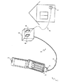
図1は、本発明の第1の実施形態に係る受信システムの構成例を示す図である。
図2は、図1の電源装置を、充電台を介して携帯電話に接続する場合を示す図である。
<1. First Embodiment>
[Configuration of Embodiment]
FIG. 1 is a diagram illustrating a configuration example of a receiving system according to the first embodiment of the present invention.
FIG. 2 is a diagram illustrating a case where the power supply device of FIG. 1 is connected to a mobile phone via a charging stand.
この受信システム1は、携帯電話2に電源装置3から充電用の電力を供給する。
この受信システム1は、この充電用の電力を伝送する電力伝送用ケーブル4をアンテナとして機能させ、携帯電話2でデジタルテレビジョン放送の放送波、ダウンロードサービスの放送波等を受信する。
なお、ダウンロードサービスの放送波は、たとえば放送波を利用して映像コンテンツをダウンロードするサービスであるメディアフロー(登録商標)の放送波である。
The receiving
In the
Note that the broadcast wave of the download service is, for example, a broadcast wave of Media Flow (registered trademark), which is a service for downloading video content using the broadcast wave.
ここで携帯電話2は、放送波の受信機能、各種コンテンツの記録再生機能を有する携帯電話であり、側面にコネクタ5が設けられる。
Here, the
電源装置3は、本体装置である携帯電話2の充電用電力を商用電源から生成する電源部6を有し、この電源部6で生成された電源を電力伝送用ケーブル4で携帯電話2に伝送する。
電源装置3は、電力伝送用ケーブル4の一端に、コネクタ7が設けられ、コネクタ7が携帯電話2のコネクタ5に接続されて携帯電話2に接続される。
The
In the
電源部6は、略矩形形状により形成され、商用電源のコンセントから商用電力を入力する端子8が一面に設けられる。
これにより、電源部6は、図1中に矢印Aにより示すように、この端子8を屋内コンセントに差し込んで、AC100〔V〕の交流商用電源から5〔V〕の充電用直流電力(電圧)を生成する。
なお受信システム1は、図1との対比により図2に示すように、充電台10を介して携帯電話2に電源装置3が接続される場合もある。
The
Thereby, as shown by arrow A in FIG. 1, the
In the
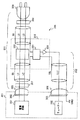
図3は、この受信システム1の要部の構成および接続関係を詳細に示す図である。
FIG. 3 is a diagram showing in detail the configuration and connection relationship of the main part of the receiving
携帯電話2は、コネクタ5のホット側電源端子が充電用の電源回路11に接続され、コネクタ5のコールド側電源端子が接地される。
携帯電話2は、コネクタ5のアンテナ入力端子がインダクタ12により接地され、キャパシタ13を介してチューナー14のアンテナ入力端に接続される。
ここでチューナー14は、上述した放送波を受信することが可能なチューナーである。なおここでインダクタ12は、マッチング回路を構成し、この実施形態では18〔nH〕に設定される。
In the
In the
Here, the
電源部6は、配線基板15上に、商用電源から充電用電力を生成する電源回路16が設けられる。
電源部6は、電源回路16で生成したホット側電源およびコールド側電源を、それぞれ高周波遮断回路17を形成するインダクタ17Lおよび17Gを介して電力伝送用ケーブル4に出力する。
なお、インダクタ17Lおよび17Gは、たとえばフェライトビーズにより構成され、商用電源側からのノイズ、高周波信号の混入を防止し、アンテナとして機能させる電力伝送用ケーブル4の電気長を設定する。
In the
The
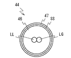
図4は、本実施形態に係る電力伝送用ケーブル4の構造例示す簡略断面図である。
図5は、図1の電源装置を詳細に示す図である。
FIG. 4 is a simplified cross-sectional view showing a structural example of the
FIG. 5 is a diagram showing in detail the power supply device of FIG.
電力伝送用ケーブル4は、図4に断面を取って示すように、2本のケーブルLLおよびLGを絶縁体により覆って一体に保持する多芯ケーブルである。
電力伝送用ケーブル4は、この2本のケーブルLLおよびLGが、それぞれホット側電源およびコールド側電源に割り当てられ、図5に示すように、ケーブルLLおよびLGの電源部6側端が配線基板15上でインダクタ17Lおよび17Gに接続される。
なお、以下において、ケーブルLL、LGを電源ケーブルと呼ぶ。
伝送ケーブルLL、LGは、それぞれアラミド繊維入りの縒り線を被覆して作製される。なお図3等において、伝送ケーブルLLおよびLGは、平行2線により一体に保持される場合を示しているものの、撚り合わされた状態で一体に保持してもよい。
The
In the
In the following, the cables LL and LG are referred to as power cables.
The transmission cables LL and LG are each manufactured by covering a twisted wire containing an aramid fiber. In addition, in FIG. 3 etc., although the transmission cables LL and LG have shown the case where it hold | maintains integrally by two parallel wires, you may hold | maintain integrally in the state twisted together.
電力伝送用ケーブル4は、図5に示すように、伝送ケーブルLLおよびLGのコネクタ7側端が、それぞれ高周波遮断回路18を形成するインダクタ18Lおよび18Gを介してコネクタ7の電源端子7L、7Gに接続される。
ここで高周波遮断回路は、高周波信号の伝送を選択的に抑圧する回路であり、この実施形態ではインダクタ18Lおよび18Gが適用される。
なおインダクタは、通常インピーダンスZがZ=jωLであり、周波数の増大により、インピーダンスZが高くなり、高周波を遮断することができる。インダクタは、さらに、インダクタに含まれるインダクタンス成分とキャパシタンス成分による自己共振を用いて、インピーダンスを最大にして用いることも可能である。
インダクタ18Lおよび18Gは、たとえばフェライトビーズにより構成され、高周波信号の携帯電話2への混入を防止し、携帯電話2からのノイズの流出を防止する。
また、電力伝送用ケーブル4は、コールド側電源に割り当てた伝送ケーブルLGのインダクタ18G側端が、コネクタ7のアンテナ入力端子7Aに接続される。
As shown in FIG. 5, the
Here, the high-frequency cutoff circuit is a circuit that selectively suppresses transmission of a high-frequency signal, and
The inductor normally has an impedance Z of Z = jωL, and an increase in frequency increases the impedance Z and can cut off high frequencies. Further, the inductor can be used by maximizing the impedance by using self-resonance due to the inductance component and the capacitance component included in the inductor.
In the
なお、電力伝送用ケーブル4は、図5に示すように、コネクタ7を実装する配線基板19上にインダクタ18Lおよび18Gが実装され、この配線基板19上で、伝送ケーブルLLおよびLGがインダクタ18Lおよび18Gに接続される。
その接続後、配線基板19を配置した背面側が、電力伝送用ケーブル4の携帯電話2側端と共に樹脂によりモールディングされる。
なお、インダクタ17L、17G、18L、18Gは、フェライトビーズに代えてチップインダクタにより形成してもよい。
5, the
After the connection, the back side on which the
The
電力伝送用ケーブル4は、インダクタ17L、17Gからインダクタ18L、18Gまでの長さL1が、この受信システム1の受信周波数の波長に対して、1/4波長の奇数倍の長さに設定される。
より具体的には、この受信システム1の受信周波数帯域の周波数190〔MHz〕の波長に対して、約3/4波長の長さ1100〔mm〕に設定される。
In the
More specifically, the length is set to about 1/4 [mm] of about 3/4 wavelength with respect to the wavelength of 190 [MHz] in the reception frequency band of the
その結果、図6に示すように、この受信システム1では、伝送ケーブルLGにより3/4波長のモノポールアンテナが形成される。
このアンテナにより、3/4波長に対応する基本周波数の帯域を受信可能とし、また、基本周波数の高調波を用いて、UHF帯域、たとえば地上波デジタルTVの470〜770〔MHz〕の放送波の受信を可能としている。
As a result, as shown in FIG. 6, in this
With this antenna, it is possible to receive a band of the fundamental frequency corresponding to 3/4 wavelength, and the harmonics of the fundamental frequency are used to transmit a UHF band, for example, a 470-770 [MHz] broadcast wave of terrestrial digital TV. Reception is possible.
〔実施形態の動作〕
以上の構成において、受信システム1では、電源装置3を携帯電話2に接続し、この電源装置3を商用電源のコンセントに接続することにより、電源装置3で商用電源から充電用の直流電力が生成される。
生成された直流電力が携帯電話2に伝送されて携帯電話2が充電される。
[Operation of Embodiment]
In the above configuration, in the receiving
The generated DC power is transmitted to the
また、受信システム1では、ユーザーの操作により携帯電話2で各種放送波を受信してコンテンツを記録した後、この記録したコンテンツを改めて携帯電話2で再生してユーザーに提供する。
In the
ここで放送波を受信する場合に、内蔵アンテナで放送波を受信したのでは、十分なアンテナ利得を確保できないことにより、弱電界のエリアでは満足に放送波を受信することが困難になる。
特に、屋内で放送波を受信する場合、各種の遮蔽物により電界強度が著しく弱くなり、その結果、著しく感度が劣化する。また携帯電話2の内部ノイズの影響も避け得ず、これによっても放送波を安定して受信できなくなる。
Here, when a broadcast wave is received, if the broadcast wave is received by the built-in antenna, a sufficient antenna gain cannot be secured, so that it is difficult to satisfactorily receive the broadcast wave in a weak electric field area.
In particular, when a broadcast wave is received indoors, the electric field strength is significantly weakened by various shields, and as a result, the sensitivity is significantly deteriorated. Moreover, the influence of the internal noise of the
そこで、ロッドアンテナを使用して放送波を受信することが考えられる。
しかしながら、ロッドアンテナを使用すると、デザインが著しく損なわれることになる。特に携帯電話2では、せいぜい10〔cm〕程度しかアンテナ長を設定できないことから、ロッドアンテナを使用する場合でも、FM放送、デジタルラジオ放送等のVHF帯域では、十分なアンテナ利得を確保し得ず、結局、受信感度が劣化することになる。
Therefore, it is conceivable to receive broadcast waves using a rod antenna.
However, the use of a rod antenna will significantly impair the design. In particular, in the
そこで、本第1の実施形態の受信システム1では、電源装置3の電源を携帯電話2に供給する電力伝送用ケーブル4をアンテナとして機能させて放送波を受信する。
この場合、内蔵アンテナを利用する場合の内部ノイズの影響を有効に回避することができ、また内蔵アンテナを利用する場合に比して感度を向上することができる。またロッドアンテナを使用する場合のデザインの劣化も防止することができる。
Therefore, in the
In this case, it is possible to effectively avoid the influence of internal noise when using the built-in antenna, and it is possible to improve sensitivity as compared with the case where the built-in antenna is used. In addition, it is possible to prevent design deterioration when using a rod antenna.
ところが単純に、電源ケーブルをアンテナとして機能させる構成を適用して、電力伝送用ケーブル4をアンテナとして機能させる場合には、十分に広い周波数帯域で、十分な利得を確保することが困難になる。
However, simply applying a configuration in which the power cable functions as an antenna and causing the
図7は、図1との対比により、特開2005−341067号公報に開示の手法を適用した受信システムを示す図である。
図7は、アンテナとして機能する伝送ケーブルLGにLC共振回路を設けた場合を例に示している。
なお、図7においては、理解を容易にするために、図3と同一機能部分は同一符号をもって表している。
FIG. 7 is a diagram illustrating a receiving system to which the technique disclosed in Japanese Patent Laid-Open No. 2005-34067 is applied in comparison with FIG.
FIG. 7 shows an example in which an LC resonance circuit is provided in the transmission cable LG that functions as an antenna.
In FIG. 7, the same functional parts as those in FIG. 3 are denoted by the same reference numerals for easy understanding.
図7の受信システム21は、電源部6側において、ホット側の伝送ケーブルLLが直接電源回路16に接続され、コールド側の伝送ケーブルLGがLC共振回路22を介して電源回路16に接続される。
また、携帯電話2側において、ホット側の伝送ケーブルLLが直接電源回路11に接続され、コールド側の伝送ケーブルLGがインダクタ12を介して接地され、キャパシタ13を介してチューナー14に接続される。
In the receiving
On the
この受信システム21では、LC共振回路22を設けることにより、広い帯域で十分なアンテナ利得を確保できない欠点がある。
また、受信システム21では、ホット側の伝送ケーブルLLとコールド側の伝送ケーブルLGとが高周波的に結合し、LC共振回路22を十分に機能させることが困難となり、これによっても十分なアンテナ利得を確保できない欠点がある。
This receiving
In the receiving
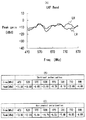
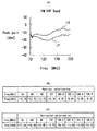
図8(A)〜図8(C)は、図7の受信システム21において延長コードを接続していない場合のVHF帯域のアンテナ特性を示す図である。
図8(A)が図7の受信システム21のVHF帯域のアンテナ利得特性を示す図である。図8(B)が図8(A)の特性図における垂直偏波(Vertical Polarization)の特性を示す図である。図8(C)が図8(A)の特性図における水平偏波(Horizontal Polarization)の特性を示す図である。図8(A)において、横軸は周波数を示しており、縦軸はアンテナ利得を示している。
FIGS. 8A to 8C are diagrams illustrating antenna characteristics in the VHF band when no extension cord is connected in the
FIG. 8A is a diagram illustrating antenna gain characteristics in the VHF band of the
図8(A)の特性は、受信システム21における共振回路22のインピーダンスを無限大とし、電源部6の端子8を何れの部位にも接続していない場合の測定結果である。
また、図8(A)の特性は、携帯電話2を想定したグランドサイズが95×45〔mm〕の評価基板にコネクタを介して電源装置を接続した場合の測定結果である。
なお、図8(A)中の符号LHおよびLVは、それぞれ水平偏波および垂直偏波を示す特性を示している。
この場合の電力伝送用ケーブル4の長さは、周波数190〔MHz〕の3/4波長に相当する1100〔mm〕である。
The characteristics of FIG. 8A are measurement results when the impedance of the
The characteristics of FIG. 8A are measurement results when the power supply device is connected to an evaluation board with a ground size of 95 × 45 [mm] assuming the
Note that symbols LH and LV in FIG. 8A indicate characteristics indicating horizontal polarization and vertical polarization, respectively.
In this case, the length of the
また、図8(B)および(C)は、図8(A)に示す測定結果を詳細に示している。
これら図8(A)〜図8(C)の測定結果では、図8(A)中に符号Bにより示すように、局所的にアンテナ利得が低下することが判る。したがって、十分に広い周波数帯域で十分な利得を確保できないことが判る。
8B and 8C show the measurement results shown in FIG. 8A in detail.
From the measurement results of FIGS. 8A to 8C, it can be seen that the antenna gain is locally reduced as indicated by reference numeral B in FIG. 8A. Therefore, it can be seen that a sufficient gain cannot be secured in a sufficiently wide frequency band.
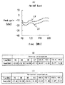
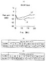
図9(A)〜図9(C)は、図8(A)〜図8(C)との対比により、図7の受信システム21において、電源部6の端子8を長さ3〔m〕の延長ケーブルに接続した場合の測定結果を示す図である。
なお測定の条件は、図8(A)〜図8(C)の場合と同一である。
これら図9(A)〜図9(C)の測定結果によれば、図8(A)〜図8(C)との対比により、図9(A)中に符号Cにより示す利得の劣化する周波数が低い周波数側に変位していることが判る。
したがって、受信システム21では、実際に商用電源のコンセントに電源部6を接続した場合には、商用電源のケーブルの引回しにより、種々にアンテナの特性が変化することになる。
また、図9(A)〜図9(C)の測定結果では、電力伝送用ケーブル4の長さに対応する周波数190〔MHz〕周辺で、アンテナ利得が約4〔dB〕劣化していることも観察される。これによっても、十分に広い周波数帯域で十分な利得を確保できないことが判る。
9 (A) to 9 (C) are compared with FIGS. 8 (A) to 8 (C), in the receiving
Measurement conditions are the same as those in FIGS. 8A to 8C.
According to the measurement results of FIGS. 9A to 9C, the gain indicated by the symbol C in FIG. 9A is deteriorated by comparison with FIGS. 8A to 8C. It can be seen that the frequency is displaced to the lower frequency side.
Therefore, in the receiving
Further, in the measurement results of FIGS. 9A to 9C, the antenna gain is degraded by about 4 [dB] around the frequency 190 [MHz] corresponding to the length of the
図10は、特開2002−151932号公報に開示の手法を適用して考えられる受信システムを示す図である。
なお、図10においては、理解を容易にするために、図3と同一機能部分は同一符号をもって表している。
FIG. 10 is a diagram illustrating a reception system that can be considered by applying the technique disclosed in Japanese Patent Application Laid-Open No. 2002-151932.
In FIG. 10, the same functional parts as those in FIG. 3 are denoted by the same reference numerals in order to facilitate understanding.
図10の受信システム31は、電源部6側において、ホット側の伝送ケーブルLLおよびコールド側の伝送ケーブルLGが直接電源回路16に接続される。
また、携帯電話2側において、ホット側の伝送ケーブルLLが直接電源回路11に接続され、コールド側の伝送ケーブルLGがインダクタ12を介して接地され、キャパシタ13を介してチューナー14に接続される。
また、伝送ケーブルLL、LVに巻回したケーブルLWがキャパシタ13およびインダクタ12の接続点に接続される。
In the receiving
On the
A cable LW wound around the transmission cables LL and LV is connected to a connection point between the
この場合、アンテナとして機能するケーブルLWのQが著しく高くなる。その結果、この場合も十分に広い周波数帯域で十分な利得を確保することが困難になる。
また、図10の受信システム31でも、延長ケーブルによって、種々にアンテナの特性が変化する。
In this case, the Q of the cable LW that functions as an antenna is remarkably increased. As a result, in this case as well, it is difficult to ensure a sufficient gain in a sufficiently wide frequency band.
Also in the receiving
そこで、本実施形態に係る図3に示す受信システム1では、伝送ケーブルLL、LGのコネクタ5、7側端とコネクタ5、7より所定長さだけ離間した部位にそれぞれ高周波遮断回路18,17を形成するインダクタ18L、18G、17L、17Gが設けられる。
これにより、受信システム1では、コネクタ5、7側のインダクタ18L、18Gにより、内部ノイズの漏出が防止され、また伝送ケーブルLL、LGに誘起した高周波信号による携帯電話2の各種悪影響が防止される。
また、電源部6側のインダクタ17L、17Gによる商用電源からのノイズ、高周波信号の混入が防止される。またインダクタ18L、18G、17L、17Gにより、アンテナとして機能する部位の電気長が設定される。
Therefore, in the receiving
As a result, in the receiving
Further, noise from the commercial power supply and high frequency signals are prevented from being mixed by the
これにより、図3の受信システム1では、既存システムに比して十分に広い周波数帯域で、十分な利得により放送波を受信することができる。また、延長ケーブルによるアンテナ特性の変動を防止することができる。
As a result, the receiving
図11(A)〜図11(C)および図12(A)〜図12(C)は、それぞれ図8(A)〜図8(C)および図9(A)〜図9(C)との対比により、図3の受信システム1におけるVHF帯域の測定結果を示す図である。
図11(A)〜図11(C)は、延長ケーブルを接続していない場合の測定結果であり、図12(A)〜図12(C)は、延長ケーブルを接続した場合の測定結果である。
なお、測定の条件は、図8(A)〜図8(C)と同一である。
11 (A) to 11 (C) and FIGS. 12 (A) to 12 (C) respectively correspond to FIGS. 8 (A) to 8 (C) and FIGS. 9 (A) to 9 (C). FIG. 4 is a diagram illustrating a measurement result of a VHF band in the
11A to 11C show the measurement results when the extension cable is not connected, and FIGS. 12A to 12C show the measurement results when the extension cable is connected. is there.
Note that the measurement conditions are the same as those shown in FIGS.
これら図11(A)〜図11(C)および図12(A)〜図12(C)の測定結果によれば、既存システムに比して十分に広い周波数帯域で、十分な利得により放送波を受信できることが判る。
また、さらに延長ケーブルを接続することによるアンテナ特性の変動を防止できることが判る。
According to the measurement results shown in FIGS. 11A to 11C and FIGS. 12A to 12C, the broadcast wave has a sufficiently wide frequency band as compared with the existing system and has a sufficient gain. Can be received.
It can also be seen that the variation in antenna characteristics due to the connection of the extension cable can be prevented.
図13(A)〜図13(C)および図14(A)〜図14(C)は、それぞれ図11(A)〜図11(C)および図12(A)〜図12(C)との対比により、図3の受信システム1におけるUHF帯域の測定結果を示す図である。
図13(A)〜図13(C)は、延長ケーブルを接続していない場合の測定結果であり、図14(A)〜図14(C)は、延長ケーブルを接続した場合の測定結果である。
なお、測定の条件は、図8(A)〜図8(C)と同一である。
FIGS. 13 (A) to 13 (C) and FIGS. 14 (A) to 14 (C) respectively correspond to FIGS. 11 (A) to 11 (C) and FIGS. 12 (A) to 12 (C). FIG. 4 is a diagram illustrating a measurement result of a UHF band in the
13A to 13C show the measurement results when the extension cable is not connected, and FIGS. 14A to 14C show the measurement results when the extension cable is connected. is there.
Note that the measurement conditions are the same as those shown in FIGS.
これら図13(A)〜図13(C)および図14(A)〜図14(C)の測定結果によれば、図3の受信システム1は、UHF帯域でも、十分に広い周波数帯域で、十分な利得により放送波を受信することができる。
さらに、受信システム1によれば、延長ケーブルを接続することによるアンテナ特性の変動を防止できることが判る。
According to the measurement results of FIGS. 13 (A) to 13 (C) and FIGS. 14 (A) to 14 (C), the
Furthermore, according to the receiving
図15(A)〜図15(C)および図16(A)〜図16(C)は、コネクタ5、7側のインダクタ18L、18Gを省略した場合の測定結果を示す図である。
その測定の条件は、図8(A)〜図8(C)と同一である。
FIGS. 15A to 15C and FIGS. 16A to 16C are diagrams showing measurement results when the
The measurement conditions are the same as those in FIGS. 8A to 8C.
この測定には、図3との対比により図17に示すように、コネクタ5、7側のインダクタ18L、18Gを省略し、携帯電話2の内部のホット側電源ラインにインダクタ32を配置した受信システムを適用する。
また、コールド側電源ラインの接地は、インダクタ12を介して実行する。
ここで図15(A)〜図15(C)は、延長ケーブルに接続しない場合のVHF帯域のアンテナ利得を示す図である。図16(A)〜図16(C)は、延長ケーブルに接続した場合のVHF帯域のアンテナ利得を示す図である。
なお、電力伝送用ケーブル4の長さは、上述したと同一の1100〔mm〕である。
In this measurement, as shown in FIG. 17 in comparison with FIG. 3, the
In addition, the grounding of the cold power supply line is performed via the
Here, FIGS. 15A to 15C are diagrams showing antenna gains in the VHF band when not connected to the extension cable. FIGS. 16A to 16C are diagrams illustrating the antenna gain in the VHF band when connected to the extension cable.
The length of the
また、図18(A)〜図18(C)および図19(A)〜図19(C)は、図17の受信システムにおけるUHF帯域のアンテナ特性を示す図である。
その測定の条件は、図8(A)〜図8(C)と同一である。
なお,図18(A)〜図18(C)は、延長ケーブルを接続しない場合の測定結果であり、図19(A)〜図19(C)は、延長ケーブルを接続した場合の測定結果である。
FIGS. 18A to 18C and FIGS. 19A to 19C are diagrams illustrating antenna characteristics in the UHF band in the reception system of FIG.
The measurement conditions are the same as those in FIGS. 8A to 8C.
18A to 18C show the measurement results when the extension cable is not connected, and FIGS. 19A to 19C show the measurement results when the extension cable is connected. is there.
これら図15(A),(B),(C)〜図19(A),(B),(C)の測定結果を図11(A)〜図11(C)および図12(A)〜図12(C)の測定結果と対比すれば、次のことが判る。
すなわち、VHF帯域では、コネクタ5、7側のインダクタ18L、18Gを省略し、携帯電話2の内部にインダクタを設けるようにしても、殆ど特性に変化がないことになる。
しかしながら、UHF帯域では、コネクタ5、7側のインダクタ18L、18Gを省略し、携帯電話2の内部にインダクタを設ける場合には、コネクタ5、7における損失の分、アンテナ利得が低下する。
このことは、図18(A)〜図18(C)の測定結果と図13(A)〜図13(C)の測定結果との対比、図19(A)〜図19(C)の測定結果と図14(A)〜図14(C)の測定結果との対比により確認することができる。
これにより、携帯電話2の内部にインダクタを設ける場合に比して、図3の受信システム1の方が安定に放送波を受信できることが判る。
The measurement results of FIGS. 15 (A), (B), (C) to FIGS. 19 (A), (B), (C) are shown in FIGS. 11 (A) to 11 (C) and FIGS. The following can be understood by comparing with the measurement result of FIG.
That is, in the VHF band, even if the
However, in the UHF band, when the
This is a comparison between the measurement results of FIGS. 18 (A) to 18 (C) and the measurement results of FIGS. 13 (A) to 13 (C), and the measurements of FIGS. 19 (A) to 19 (C). It can confirm by contrast with a result and the measurement result of FIG. 14 (A)-FIG.14 (C).
Thus, it can be seen that the receiving
図20(A),(B),(C)〜図23(A),(B),(C)は、評価基板に代えて実際の携帯電話を使用した場合の測定結果を示す図である。
図20(A)〜図20(C)および図22(A)〜図22(C)は、インダクタ17L、17G、18L、18Gを省略して電力伝送用ケーブルを電源部6およびコネクタ7に直接接続した場合の測定結果で、それぞれVHF帯域およびUHF帯域の特性を示す。
また、図21(A)〜図21(C)および図23(A)〜図23(C)は、図3の受信システム1におけるVHF帯域およびUHF帯域の特性を示している。
なお、図20(A),(B),(C)〜図23(A),(B),(C)は、延長コードを接続した場合の特性を示している。
20 (A), (B), (C) to FIG. 23 (A), (B), (C) are diagrams showing measurement results when an actual mobile phone is used instead of the evaluation board. .
20A to 20C and 22A to 22C, the
21A to 21C and FIGS. 23A to 23C show the characteristics of the VHF band and the UHF band in the
20A, 20B, and 20C to FIG. 23A, 23B, and 23C show characteristics when an extension cord is connected.
これら図20(A),(B),(C)〜図23(A),(B),(C)によれば、次のことが判る。
すなわち、図3の受信システム1では、電力伝送用ケーブルにインダクタを設けない場合に比して、VHF帯域およびUHF帯域の双方でアンテナ利得を10〔dB〕以上改善し、広い周波数帯域で十分なアンテナ利得を確保できることが判る。
20 (A), (B), and (C) to FIGS. 23 (A), (B), and (C), the following can be understood.
That is, in the receiving
〔実施形態の効果〕
以上のように、本第1の実施形態においては、電力伝送用ケーブルをアンテナとして利用する構成において、電力伝送用ケーブルのコネクタ側端とこのコネクタより所定長さだけ離間した部位にそれぞれ高周波遮断回路を設けている。
これにより、本第1の実施形態の受信システム1によれば、既存システムに比して十分に広い周波数帯域で、十分な利得により放送波を受信することができる。
[Effect of the embodiment]
As described above, in the first embodiment, in the configuration in which the power transmission cable is used as an antenna, the high-frequency cutoff circuit is provided at the connector side end of the power transmission cable and a portion spaced apart from the connector by a predetermined length. Is provided.
Thereby, according to the receiving
<2.第2の実施形態>
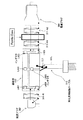
図24は、図3との対比により、本発明の第2の実施形態に係る受信システムの要部の構成および接続関係を詳細に示す図である。
図25は、本第2の実施形態に係る電力伝送用ケーブルの構造例示す簡略断面図である。
図26は、図24の電源装置を詳細に示す図である。
<2. Second Embodiment>
FIG. 24 is a diagram showing in detail the configuration and connection relationship of the main part of the receiving system according to the second embodiment of the present invention, in comparison with FIG.
FIG. 25 is a simplified cross-sectional view showing a structural example of a power transmission cable according to the second embodiment.
FIG. 26 is a diagram showing in detail the power supply device of FIG.
この受信システム41は、携帯電話2、電源装置3に代えて携帯電話42、電源装置43が適用される。
なお、図24の受信システム41において、受信システム1と同一の構成は、対応する符号を付して示し、重複した説明は省略する。
In this receiving
In the receiving
ここで、携帯電話42は、コネクタ5のコールド側電源端子が、インダクタ12、キャパシタ13の接続点に接続され、インダクタ12を介して接地される点を除いて、第1の実施形態の携帯電話2と同一に構成される。
Here, the
電源装置43は、電力伝送用ケーブル4に代えて電力伝送用ケーブル44が適用される。電源装置43は、この電力伝送用ケーブル44に関する構成が異なる点を除いて、第1の実施形態の電源装置3と同一に構成される。
A
ここで電力伝送用ケーブル44は、図25に断面をとって示すように、いわゆる多芯同軸ケーブルにより形成され、2本の芯線ケーブルLLおよびLGを被覆線SSで被覆して作製される。
なお、電力伝送用ケーブル44において、芯線ケーブルLL、LGは、それぞれアラミド繊維入りの縒り線を被覆して作製され、縒り合わされた後、絶縁体46により覆って一体に保持される。
電力伝送用ケーブル44は、この絶縁体46を囲むように銅の網線による被覆線SSが配置され、全体をエラストマーで覆って外皮47が作製される。
Here, the
In the
In the
電源装置43は、芯線ケーブルLL、LGがそれぞれホット側およびコールド側の電源伝送に割り当てられる。
したがって、電源装置43は、図26に示すように、芯線ケーブルLL、LGの電源部6側端がそれぞれ配線基板15上でインダクタ17L、17Gに接続され、インダクタ17L、17Gを介して電源回路16に接続される。
また、芯線ケーブルLL、LGの携帯電話42側端がそれぞれ配線基板19上でインダクタ18L、18Gに接続され、インダクタ18L、18Gを介してコネクタ7の電源端子7L、7Gに接続される。
In the
Therefore, as shown in FIG. 26, in the
Moreover, the
また、電源装置43は、被覆線SSにアンテナの機能が割り当てられ、被覆線SSの電源部6側端が何れの部位にも接続されていない、いわゆる開放端とされる。
また、被覆線SSの携帯電話42側端が配線基板19上でコネクタ7のアンテナ入力端子7Aに接続される。
電源装置43は、インダクタ17L、17Gからインダクタ18L、18Gまでの長さL1が、周波数190〔MHz〕の波長に対して約3/4波長の長さに設定される。
The
Further, the end of the covered wire SS on the
In the
これにより、図24の受信システム41は、被覆線SSをアンテナとして機能させ、この被覆線SSと高周波的に結合する芯線ケーブルLLおよびLGの電気長をインダクタ17L、17G、18L、18Gで制限する。
Accordingly, the
図27(A)〜図27(C)および図28(A)〜図28(C)は、それぞれ延長コードを接続していない場合、延長コードを接続した場合について、図24の受信システム41によるVHF帯域のアンテナ特性を示す図である。
また、図29(A)〜図29(C)および図30(A)〜図30(C)は、それぞれ延長コードを接続していない場合、延長コードを接続した場合について、図24の受信システム41によるUHF帯域のアンテナ特性を示す図である。
27 (A) to 27 (C) and 28 (A) to 28 (C) respectively show the case where the extension cord is not connected and the case where the extension cord is connected according to the
29 (A) to 29 (C) and FIGS. 30 (A) to 30 (C) respectively show the reception system of FIG. 24 when the extension cord is not connected and when the extension cord is connected. FIG. 4 is a diagram showing antenna characteristics in the UHF band by 41;
これら図27(A),(B),(C)〜図30(A),(B),(C)の測定結果によれば、図24の受信システム41では、延長ケーブルによるアンテナ利得の変動を十分に防止して、広い周波数帯域で十分な利得を確保できることが判る。
また、図24の受信システム41では、芯線ケーブルLL、LGと絶縁された被覆線SSをアンテナとして機能させるようにしたことにより、UHF帯域において、第1の実施形態の受信システム1に比して、アンテナ利得を向上できることが判る。
According to the measurement results of FIGS. 27A, 27B, and 30C to 30A, 30B, and 30C, in the
In addition, in the
なお、電源装置43では、電力伝送用ケーブル44を束ねて使用する場合がある。この場合、アンテナ利得が低下するおそれがある。
図31(A),(B),(C)〜図34(A),(B),(C)は、電力伝送用ケーブル44を束ねた場合のアンテナ利得の確認に供する測定結果を示す図である。
図31(A)〜図31(C)および図32(A)〜図32(C)は、電力伝送用ケーブル44を垂直に垂らした場合および電力伝送用ケーブル44を束ねた場合のVHF帯域の測定結果を示している。
また、図33(A)〜図33(C)および図34(A)〜図34(C)は、電力伝送用ケーブル44を垂直に垂らした場合および電力伝送用ケーブル44を束ねた場合のUHF帯域の測定結果を示している。
なおこれらは上述した評価基板を用いた測定結果である。
In the
FIGS. 31 (A), (B), (C) to FIGS. 34 (A), (B), (C) are diagrams showing measurement results used for checking the antenna gain when the
31 (A) to 31 (C) and 32 (A) to 32 (C) show the VHF band when the
33 (A) to 33 (C) and FIGS. 34 (A) to 34 (C) show UHF when the
These are measurement results using the above-described evaluation substrate.
図31(A),(B),(C)〜図34(A),(B),(C)の測定結果によれば、次のことが判る。
すなわち、第2の実施形態の受信システム41では、VHF帯域では電力伝送用ケーブル44を束ねることにより、低い周波数で利得の劣化が著しいものの、UHF帯域では電力伝送用ケーブル44を束ねても、十分に実用に供する利得を確保できることが判る。
According to the measurement results of FIGS. 31 (A), (B), (C) to FIGS. 34 (A), (B), (C), the following can be understood.
That is, in the receiving
この第2の実施形態では、電力伝送用ケーブルに多芯同軸ケーブルを使用する場合でも、第1の実施形態と同一の効果を得ることができる。 In the second embodiment, even when a multi-core coaxial cable is used as the power transmission cable, the same effect as that of the first embodiment can be obtained.
<3.第3の実施形態>
図35は、図24との対比により、本発明の第3の実施形態に係る受信システムの要部の構成および接続関係を詳細に示す図である。
<3. Third Embodiment>
FIG. 35 is a diagram showing in detail the configuration and connection relationship of the main part of the receiving system according to the third embodiment of the present invention, in comparison with FIG.
図35の受信システム51は、携帯電話42に代えて、第1の実施形態について上述した携帯電話2が適用される点を除いて、第2の実施形態の受信システム41と同一に構成される。
したがって、受信システム51では、コールド側芯線ケーブルLGを被覆線SSと物理的に分離して携帯電話2の内部で接地する。
The
Therefore, in the
この第3の実施形態によれば、コールド側芯線ケーブルを被覆線と物理的に分離して接地することにより、アンテナとして機能する部位のアイソレーションを一段と向上することができる。
したがって、電源ノイズ等による影響を低減して、第2の実施形態と同様の効果を得ることができる。
According to the third embodiment, by isolating the cold-side core wire cable from the coated wire and grounding it, the isolation of the part that functions as an antenna can be further improved.
Therefore, it is possible to reduce the influence of power supply noise and the like and obtain the same effect as in the second embodiment.
<4.第4の実施形態>
図36は、図35との対比により、本発明の第4の実施形態に係る受信システムの要部の構成および接続関係を詳細に示す図である。
<4. Fourth Embodiment>
FIG. 36 is a diagram showing in detail the configuration and connection relationship of the main part of the reception system according to the fourth embodiment of the present invention, in comparison with FIG.
図36の受信システム61は、電源装置43に代えて、電源装置63が適用される点を除いて、第3の実施形態に係る受信システム51と同一に構成される。
The receiving
ここで電源装置63は、電力伝送用ケーブル44に代えて電力伝送用ケーブル64が適用され、この電力伝送用ケーブル64に関する構成が異なる点を除いて、上述の電源装置43と同一に構成される。
Here, the
また電力伝送用ケーブル64は、被覆線SSに関する構成が異なる点を除いて、電力伝送用ケーブル44と同一に構成される。
電力伝送用ケーブル64は、コネクタ7から一定の距離L2で被覆線SSが切断されて開放端とされる。
また、配線基板19上において、コールド側の芯線ケーブルLGが被覆線SSに接続される。
これにより、電力伝送用ケーブル64は、インダクタ17L、17Gおよび18L、18G間の長さL1、被覆線SSの長さL2にそれぞれ対応する2周波のアンテナとして機能するように構成される。
The
The
Further, on the
Thereby, the
この第4の実施形態では、被覆線SSによるアンテナにより、芯線ケーブルLL、LGによるアンテナの機能を補い、UHF帯域における局所的なアンテナ利得の低下を防止する。
具体的に、芯線ケーブルLL、LGのみによりUHF帯域を受信して局所的にアンテナ利得が低下する周波数に対して、被覆線SSの長さL2が、1/4波長の奇数倍となるように設定し、UHF帯域における局所的なアンテナ利得の低下を防止する。
In the fourth embodiment, the antenna of the core wire cables LL and LG is supplemented by the antenna of the covered wire SS, and the local decrease in antenna gain in the UHF band is prevented.
Specifically, the length L2 of the covered wire SS is an odd multiple of a quarter wavelength with respect to the frequency at which the antenna gain is locally reduced by receiving the UHF band only by the core cables LL and LG. Set to prevent local antenna gain degradation in the UHF band.
この第4の実施形態では、被覆線を途中で切断して2周波のアンテナとして機能するように構成することにより、一段と性能を向上して、上述の実施形態と同様の効果を得ることができる。 In the fourth embodiment, by cutting the coated wire halfway and functioning as a two-frequency antenna, the performance can be further improved and the same effect as the above-described embodiment can be obtained. .
<5.第5の実施形態>
図37は、図3との対比により、本発明の第5の実施形態に係る受信システムの要部の構成および接続関係を詳細に示す図である。
<5. Fifth Embodiment>
FIG. 37 is a diagram showing in detail the configuration and connection relationship of the main part of the receiving system according to the fifth embodiment of the present invention, in comparison with FIG.
図37の受信システム71は、電源装置3に代えて電源装置73が適用される点を除いて、第1の実施形態の受信システム1と同一に構成される。
The receiving
電源装置73は、インダクタ17L、17Gが省略されて電源部76が構成される。
また電源装置73は、このインダクタ17L、17Gの代わりに、電力伝送用ケーブル4にフェライトコア74が配置され、このフェライトコア74により伝送ケーブルLLおよびLGにそれぞれインダクタが配置される。
電源装置73は、これらインダクタ17L、17Gに関する構成が異なる点を除いて図1の電源装置3と同一に構成される。
In the
In the
The
ここでフェライトコア74は、円筒形状により形成される。
電源装置73は、図38に示すように、コネクタ7から一定距離L3だけ離間した部位でフェライトコア74に電力伝送用ケーブル4が1回だけ巻回され、これによりフェライトコア74が配置される。
なお、必要に応じて単に電力伝送用ケーブル4をフェライトコア74に挿通するだけでもよい。
Here, the
As shown in FIG. 38, in the
Note that the
図39(A)〜図39(C)および図40(A)〜図40(C)は、それぞれ延長ケーブルを接続しない場合および延長ケーブルを接続した場合の、図37の受信システム71のVHF帯域における測定結果を示す図である。
これら図39(A)〜図39(C)および図40(A)〜図40(C)は、電力伝送用ケーブル4の長さを1100〔mm〕とし、電源部76側端にフェライトコア74を配置した場合である。
39 (A) to 39 (C) and FIGS. 40 (A) to 40 (C) show the VHF band of the
39 (A) to 39 (C) and FIGS. 40 (A) to 40 (C), the length of the
また、図41(A)〜図41(C)および図42(A)〜図42(C)は、それぞれ延長ケーブルを接続しない場合および延長ケーブルを接続した場合の、図37の受信システム71のVHF帯域における測定結果を示す図である。
これら図41(A)〜図41(C)および図42(A)〜図42(C)は、電力伝送用ケーブル4の全長L4を1600〔mm〕とし、フェライトコア74を配置した部位までの距離L3を1100〔mm〕とした場合である。
41 (A) to 41 (C) and FIGS. 42 (A) to 42 (C) respectively show the
41 (A) to 41 (C) and FIGS. 42 (A) to 42 (C), the total length L4 of the
これら図39(A),(B),(C)〜図42(A),(B),(C)の測定結果によれば、次のことが判る。
すなわち、伝送ケーブルLL、LGにそれぞれインダクタを配置する代わりに、電力伝送用ケーブル4にフェライトコア74によりインダクタを配置するようにしても、十分に広い周波数帯域で、十分な利得を確保できることが判る。
According to the measurement results of FIGS. 39 (A), (B), (C) to FIGS. 42 (A), (B), (C), the following can be understood.
That is, it can be understood that a sufficient gain can be secured in a sufficiently wide frequency band even if an inductor is disposed in the
この第5の実施形態によれば、伝送ケーブルLL、LGにそれぞれインダクタを配置する代わりに、電力伝送用ケーブルにフェライトコアによりインダクタを配置するようにしても、上述の実施形態と同様の効果を得ることができる。
また、電力伝送用ケーブルの全長に対してフェライトコアの配置位置を種々に設定できることにより、電力伝送用ケーブルの長さを種々に変更して使い勝手を向上することができる。
According to the fifth embodiment, the same effect as that of the above-described embodiment can be obtained by arranging an inductor with a ferrite core in a power transmission cable instead of arranging an inductor in each of the transmission cables LL and LG. Can be obtained.
Moreover, since the arrangement position of the ferrite core can be variously set with respect to the entire length of the power transmission cable, the length of the power transmission cable can be variously changed to improve usability.
<6.第6の実施形態>
図43は、図35との対比により、本発明の第6の実施形態に係る受信システムの要部の構成および接続関係を詳細に示す図である。
<6. Sixth Embodiment>
FIG. 43 is a diagram showing in detail the configuration and connection relationship of the main part of the reception system according to the sixth embodiment of the present invention, in comparison with FIG.
図43の受信システム81は、電力伝送用ケーブル44が所定長さL1に設定され、この電力伝送用ケーブル44の電源部6側端にフェライトコア74が配置される。
また、芯線ケーブルLLおよびLGが、インダクタ17Lおよび17Gを介して電源回路16に接続される。
これにより、受信システム81は、電源部6側において、フェライトコア74とインダクタ17Lおよび17Gとにより2重にノイズ、高周波信号の進入を防止する。
したがって、周波数30〔MHz〕以下の電源ノイズの影響を格段的に低減することができる。
In the
Core wire cables LL and LG are connected to
As a result, the
Therefore, the influence of power supply noise having a frequency of 30 [MHz] or less can be significantly reduced.
この第6の実施形態では、電源部側に、フェライトコアとインダクタとを配置することにより、一段とノイズ、高周波信号の進入を防止して、上述の実施形態と同様の効果を得ることができる。 In the sixth embodiment, by arranging the ferrite core and the inductor on the power supply unit side, the noise and the high frequency signal can be prevented from entering further, and the same effect as the above-described embodiment can be obtained.
<7.第7の実施形態>
この第7の実施形態では、中継ケーブルを介して電源装置で生成した電源を携帯電話に伝送する。
中継ケーブルは、電力伝送用ケーブルの両端にコネクタ5、7にそれぞれ接続するコネクタが設けられる。
この第7の実施形態では、この中継ケーブルに、上述の各実施形態に係る電力伝送ケーブルに関する構成が適用され、これにより中継ケーブルをアンテナとして機能させる。
<7. Seventh Embodiment>
In the seventh embodiment, the power generated by the power supply device is transmitted to the mobile phone via the relay cable.
The relay cable is provided with connectors for connecting to the
In the seventh embodiment, the configuration related to the power transmission cable according to each of the above-described embodiments is applied to the relay cable, thereby causing the relay cable to function as an antenna.
この第7の実施形態によれば、中継ケーブルを介して電源装置で生成した電源を携帯電話に伝送するようにして、この中継ケーブルに上述の各実施形態の構成を適用してアンテナとして機能させるようにしても、上述の各実施形態と同様の効果を得ることができる。 According to the seventh embodiment, the power generated by the power supply device is transmitted to the mobile phone via the relay cable, and the configuration of each of the above-described embodiments is applied to the relay cable so as to function as an antenna. Even if it does, the effect similar to each above-mentioned embodiment can be acquired.
<第8の実施形態>
この第8の実施形態では、コネクタ7に設けられる配線基板19に増幅回路が配置され、アンテナとして機能する部位に誘起された高周波信号を増幅して携帯電話に出力する。
この第8の実施形態では、この増幅回路に関する構成が異なる点を除いて、上述の実施形態と同一に構成される。
<Eighth Embodiment>
In the eighth embodiment, an amplifier circuit is disposed on the
The eighth embodiment has the same configuration as the above-described embodiment except that the configuration related to the amplifier circuit is different.
この実施形態では、増幅回路で高周波信号を増幅することにより、一段と感度を向上して上述の各実施形態と同一の効果を得ることができる。 In this embodiment, by amplifying the high-frequency signal by the amplifier circuit, the sensitivity can be further improved and the same effects as those of the above-described embodiments can be obtained.
<9.第9の実施形態>
上述の各実施形態においては、コネクタのアンテナ端子を介して、アンテナとして機能する部位をチューナーに接続する場合について述べた。
しかしながら本発明はこれに限らず、たとえば図24および図36との対比により図44および図45に示すように、電源端子を介して、アンテナとして機能する部位をチューナーに接続してもよい。
<9. Ninth Embodiment>
In each of the above-described embodiments, the case where the part that functions as an antenna is connected to the tuner via the antenna terminal of the connector has been described.
However, the present invention is not limited to this. For example, as shown in FIGS. 44 and 45 in comparison with FIGS. 24 and 36, a portion that functions as an antenna may be connected to the tuner via a power supply terminal.
また、上述の実施形態においては、アンテナとして機能する部位を受信周波数の波長に対して3/4波長または1/4波長の長さに設定する場合について述べた。
しかしながら本発明はこれに限らず、受信システムの受信周波数の波長に対して1/4波長の奇数倍の長さに種々に選定することができる。
In the above-described embodiment, the case where the part that functions as an antenna is set to a length of 3/4 wavelength or 1/4 wavelength with respect to the wavelength of the reception frequency has been described.
However, the present invention is not limited to this, and various lengths that are odd multiples of a quarter wavelength with respect to the wavelength of the reception frequency of the reception system can be selected.
また、上述の第5の実施形態においては、電源装置のケーブルを多芯ケーブルにより構成する場合について述べたが、本発明はこれに限らず、電源装置のケーブルを多芯同軸ケーブルにより構成する場合にも広く適用することができる。 In the fifth embodiment described above, the case where the cable of the power supply device is constituted by a multicore cable has been described. However, the present invention is not limited to this, and the case where the cable of the power supply device is constituted by a multicore coaxial cable. Can also be widely applied.
また、上述の第6の実施形態においては、電源装置のケーブルを多芯同軸ケーブルにより構成する場合について述べたが、本発明はこれに限らず、電源装置のケーブルを多芯ケーブルにより構成する場合にも広く適用することができる。 Further, in the above-described sixth embodiment, the case where the cable of the power supply device is configured by a multi-core coaxial cable has been described, but the present invention is not limited to this, and the case of configuring the cable of the power supply device by a multi-core cable. Can also be widely applied.
また、上述の実施形態では、それぞれ好適な受信システムの構成を説明したが、本発明はこれの構成に限らず、必要に応じて上述の構成を組み合わせて受信システムを構成してもよい。 In the above-described embodiments, the configuration of a suitable receiving system has been described. However, the present invention is not limited to this configuration, and the receiving system may be configured by combining the above-described configurations as necessary.
また、上述の実施形態においては、充電用の電源を生成する電源装置のケーブルをアンテナとして使用する場合について述べた。しかし、本発明はこれに限らず、商用電源を本体装置に伝送する電源コード等、本体装置に接続される電源ケーブルによりアンテナを構成する場合に広く適用することができる。 In the above-described embodiment, the case where the cable of the power supply device that generates the power supply for charging is used as the antenna has been described. However, the present invention is not limited to this, and can be widely applied to the case where the antenna is configured by a power cable connected to the main device, such as a power cord for transmitting commercial power to the main device.
また、上述の実施形態においては、本発明を携帯電話に適用する場合について述べたが、本発明はこれに限らず、受信機能を有する携帯型音楽プレイヤーに本発明を適用する場合等、受信機能を有する各種の携帯型の装置に広く適用することができる。 In the above-described embodiment, the case where the present invention is applied to a mobile phone has been described. However, the present invention is not limited to this, and a reception function such as a case where the present invention is applied to a portable music player having a reception function. It can be widely applied to various portable devices having
上述した第1〜第9の実施形態においては、電源装置、電源ケーブル、および受信装置を適用する電子機器として、たとえばデジタルテレビジョン放送等を受信可能な携帯電話に適用する場合を例に説明した。
第1〜第9の実施形態では、電力伝送用ケーブルをアンテナとして利用する構成において、電力伝送用ケーブルのコネクタ側端とこのコネクタより所定長さだけ離間した部位にそれぞれ高周波遮断回路を配置している。
これにより、第1〜第9の実施形態においては、既存システムに比して十分に広い周波数帯域で、十分な利得により放送波を受信できる受信システムを実現した。
In the first to ninth embodiments described above, a case where the power supply device, the power cable, and the receiving device are applied to a mobile phone capable of receiving, for example, digital television broadcasting has been described as an example. .
In the first to ninth embodiments, in a configuration in which a power transmission cable is used as an antenna, a high-frequency cutoff circuit is disposed at a connector side end of the power transmission cable and a portion separated by a predetermined length from the connector. Yes.
Thus, in the first to ninth embodiments, a reception system that can receive broadcast waves with a sufficient gain in a frequency band sufficiently wider than that of the existing system is realized.
以下では、電源装置、電源ケーブル、および受信装置を、携帯電話以外の電子機器、たとえばデジタルテレビジョン受像機に適用した実施形態について説明する。
以下に説明する実施形態では、電力伝送用ケーブルを利用してダイポールアンテナのエレメントを形成し、同軸ケーブル等を介してテレビジョン受像機のアンテナ用コネクタに接続可能とする。
これにより、既存システムに比してアンテナに関する携帯性を向上し、広い周波数帯域で、十分な利得により放送波を受信することができるようにする。
Hereinafter, an embodiment in which the power supply device, the power cable, and the reception device are applied to an electronic device other than a mobile phone, for example, a digital television receiver will be described.
In the embodiment described below, an element of a dipole antenna is formed using a power transmission cable and can be connected to an antenna connector of a television receiver via a coaxial cable or the like.
Thereby, the portability of the antenna is improved as compared with the existing system, and the broadcast wave can be received with a sufficient gain in a wide frequency band.
図46は、一般的なテレビジョン受像機を背面側から見て示す図である。 FIG. 46 is a diagram showing a general television receiver as viewed from the back side.
テレビジョン受像機201は、図46に背面側から見て示すように、背面から延長する電源ケーブル202を家庭内のコンセント203に接続して商用電源からの電力を入力する。
また、テレビジョン受像機201は、背面にアンテナ用コネクタ204が設けられ、このアンテナ用コネクタ204を同軸ケーブル205で、家庭内アンテナコンセント207を介して屋外アンテナ208に接続して放送波を受信する。
なお、テレビジョン受像機201には、ロッドアンテナによる受信用アンテナ209が設けられるものもある。
As shown in FIG. 46 when viewed from the rear side, the television receiver 201 inputs power from a commercial power source by connecting a power cable 202 extending from the rear side to a household outlet 203.
In addition, the television receiver 201 is provided with an
Note that some television receivers 201 are provided with a receiving antenna 209 using a rod antenna.
ところで、テレビジョン受像機201は、小型化、軽量化により、携帯して種々の場所で使用される。
たとえば台所等のアンテナ接続用の家庭内アンテナコンセント207が設けられていない場所で使用される場合がある。
この場合、テレビジョン受像機201は、家庭内アンテナコンセントが設けられている部屋から同軸ケーブルを延長して接続することが必要になる。また、家庭内アンテナコンセントが設けられている部屋で使用する場合でも、改めて同軸ケーブルを引き回して接続することが必要になる。
その結果、テレビジョン受像機は、小型化、軽量化により携帯性が向上しているにも係わらず、アンテナに関して携帯性が著しく損なわれる場合がある。
By the way, the television receiver 201 is portable and used in various places due to the reduction in size and weight.
For example, it may be used in a place such as a kitchen where a home antenna outlet 207 for antenna connection is not provided.
In this case, the television receiver 201 needs to be connected by extending a coaxial cable from a room where a home antenna outlet is provided. In addition, even when used in a room where a home antenna outlet is provided, it is necessary to reconnect the coaxial cable.
As a result, although the television receiver is improved in portability due to reduction in size and weight, the portability of the antenna may be significantly impaired.
また、テレビジョン放送の受信機能を有するノート型PC等にあっても、テレビジョン放送を受信する場合と同様に、アンテナに関して携帯性が著しく損なわれる場合がある。 Further, even in a notebook PC or the like having a television broadcast receiving function, the portability of the antenna may be significantly impaired as in the case of receiving a television broadcast.
そこで、以下に示す実施形態では、このような状況に対応して、ダイポールアンテナとして機能するように電源ケーブル(電源コード)を構成し、この電源ケーブルで放送波を受信する。 Therefore, in the embodiment shown below, in response to such a situation, a power cable (power cord) is configured to function as a dipole antenna, and broadcast waves are received by this power cable.
<10.第10の実施形態>
〔実施形態の構成〕
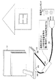
図47は、本発明の第10の実施形態に係る電子機器としてのテレビジョン受像機および電源ケーブルを含む受信装置を背面側から見て示す図である。
<10. Tenth Embodiment>
[Configuration of Embodiment]
FIG. 47 is a diagram showing a receiving device including a television receiver and a power cable as an electronic apparatus according to the tenth embodiment of the present invention when viewed from the back side.
このテレビジョン受像機301は、電源用プラグ302およびアンテナ用コネクタ303が背面に設けられる。
テレビジョン受像機301は、電源用プラグ302およびアンテナ用コネクタ303に電源ケーブル304が接続され、この電源ケーブル304を介して商用電源に接続して商用電力を入力し、かつ、この電源ケーブル304で放送波を受信する。
The
In the
電源ケーブル304は、テレビジョン受像機301側が2股に分岐するケーブルであり、この2股に分岐した一方側の先端に電源ジャック305が配置される。また、2股に分岐した他方側の先端に高周波コネクタ306が配置される。
また、テレビジョン受像機301側とは逆側端にプラグ309が配置され、このプラグ309が家庭内コンセント310に接続される。
電源ケーブル304は、電源ジャック305および高周波コネクタ306が電源用プラグ302およびアンテナ用コネクタ303に接続されてテレビジョン受像機301に接続される。
The
In addition, a
The
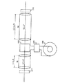
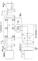
図48は、本第10の実施形態に係るテレビジョン受像機および電源ケーブルの要部の構成および接続関係を詳細に示す図である。 FIG. 48 is a diagram showing in detail the configuration and connection relationships of the main parts of the television receiver and the power cable according to the tenth embodiment.
電源ケーブル304は、電力伝送用ケーブル311の途中に、信号伝送用ケーブル312を接続して作製される。以下、電力伝送用ケーブル311に信号伝送用ケーブル312を接続する部位を中継部と呼び、符号313で示す。
The
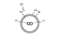
図49は、本第10の実施形態に係る図48の電力伝送用ケーブルの構造例示す簡略断面図である。 49 is a simplified cross-sectional view showing a structural example of the power transmission cable of FIG. 48 according to the tenth embodiment.
電力伝送用ケーブル311は、図49に断面をとって示すように、いわゆる多芯同軸ケーブルであり、2本の芯線ケーブルL1およびL2を被覆線SSで被覆して作製される。 電力伝送用ケーブル311において、芯線ケーブルL1、L2は、それぞれアラミド繊維入りの縒り線を被覆して作製され、絶縁体314により覆って一体に保持される。
電力伝送用ケーブル311は、この絶縁体314を囲むように銅の網線による被覆線SSが配置され、全体をエラストマーで覆って外皮315が作製される。
The
In the
電力伝送用ケーブル311は、芯線ケーブルL1およびL2が商用電力の伝送に割り当てられ、それぞれ電源ジャック305、プラグ309の対応する端子に接続される。
In the
電力伝送用ケーブル311は、電源ジャック305側端およびプラグ309側端に局所的に被覆線SSを配置していない部位が形成される。
電力伝送用ケーブル311は、この被覆線SSを配置していない部位に、それぞれフェライトコア317、318が配置され、芯線ケーブルL1およびL2の高周波信号を抑圧するインダクタが配置される。
フェライトコア317および318は、筒形状であり、電力伝送用ケーブル311を挿通して、または巻回して配置される。電力伝送用ケーブル311は、フェライトコア317および318間に、中継部313が配置される。
In the
In the
電力伝送用ケーブル311は、中継部313に、局所的に被覆線SSを配置していない部位が形成される。
したがって、電力伝送用ケーブル311は、フェライトコア317から中継部313までの部位と、フェライトコア318から中継部313までの部位とに、被覆線SSが分断される。
電源ケーブル304は、このフェライトコア317から中継部313までの被覆線SSと、フェライトコア318から中継部313までの被覆線SSで、放送波を受信するダイポールアンテナのエレメントが構成される。
In the
Therefore, in the
The
電力伝送用ケーブル311は、被覆線SSの各部位のフェライトコア317側端およびフェライトコア318側端が、それぞれ何れの部位にも接続されていない開放端とされる。
また、電力伝送用ケーブル311は、被覆線SSの各部位の中継部313側端が、平衡不平衡変換器(バラン)320を介して信号伝送用ケーブル312に接続される。
ここでバラン320は、変換比率が1:1の平衡、不平衡の信号変換機能を有する。
なお、信号伝送用ケーブル312は、同軸ケーブルにより形成され、一端に高周波コネクタ306が配置される。
より具体的には、電力伝送用ケーブル311は、電源ジャック305側の被覆線SSおよびプラグ309側の被覆線SSが、それぞれバラン320を介して信号伝送用ケーブル312の被覆線SSLおよび芯線LL1に接続される。
In the
In addition, the
Here, the
The
More specifically, in the
電力伝送用ケーブル311は、電源ジャック305側の被覆線SSおよびプラグ309側の被覆線SSの間にフェライトコア317、318と同様にフェライトコア322が配置され、芯線ケーブルL1およびL2の高周波信号を抑圧するインダクタが配置される。
電力伝送用ケーブル311は、このフェライトコア322により芯線ケーブルL1およびL2が電源ジャック305側の部位とプラグ309側の部位とに高周波的に分離される。
In the
In the
なお、図48において、符号331は、商用電源からテレビジョン受像機1の動作用電源を生成する電源回路を示し、符号332は、放送波を受信するチューナーを示している。
In FIG. 48,
図50は、本第10の実施形態に係る中継部313(分岐部)の構成例を示す図である。
図51は、アンテナとして機能する部位の長さについて説明するための図である。
FIG. 50 is a diagram illustrating a configuration example of the relay unit 313 (branching unit) according to the tenth embodiment.
FIG. 51 is a diagram for describing the length of a portion that functions as an antenna.
中継部313は、配線基板324にバラン320が実装され、この配線基板324上で、電源ジャック305側の被覆線SSおよびプラグ309側の被覆線SSがバラン320に接続される。
また、配線基板324上で、信号伝送用ケーブル312がバラン320に接続される。中継部313は、破線により示すように、その後、全体が樹脂でモールディングされる。
In the
In addition, the
図51に示すように、電力伝送用ケーブル311は、電力伝送用ケーブル311の中央よりテレビジョン受像機301側に偏った位置に中継部313が配置される。
その結果、電力伝送用ケーブル311は、電源ジャック305側の被覆線SSが、たとえばVHF帯域の中心周波数の波長に対して、1/4波長の長さに設定される。
これに対して、プラグ309側の被覆線SSが、電源ジャック305側の被覆線SSより長さが長くなるように設定される。
より具体的に、この第10の実施形態では、電源ジャック305側の被覆線SSが長さ150〔mm〕に設定され、プラグ309側の被覆線SSが長さ1000〔mm〕に設定される。なお、電源ケーブル(電源コード)の全長は、1200〔mm〕である。
As shown in FIG. 51, in the
As a result, in the
On the other hand, the covered wire SS on the
More specifically, in the tenth embodiment, the covered wire SS on the
〔第10の実施形態の動作〕
以上の構成において、このテレビジョン受像機301では(図47)、背面に設けられた電源用プラグ302に電源ケーブル304を接続し、この電源ケーブル304を商用電源のコンセントに差し込む。これにより、テレビジョン受像機301は、電源ケーブル304を介して供給される商用電力源により動作する。
また、テレビジョン受像機301は、背面にアンテナ用コネクタ303が設けられ、このアンテナ用コネクタ303に同軸ケーブルを接続して屋外アンテナを接続することにより、放送波を受信して所望のチャンネルを受信することができる。
[Operation of Tenth Embodiment]
In the above configuration, in the television receiver 301 (FIG. 47), the
In addition, the
ところが、既に述べたように、テレビジョン受像機301を移動してたとえば台所等の家庭内アンテナコンセントが設けられていない場所で使用する場合、次の作業が必要となる。
すなわち、家庭内アンテナコンセントが設けられている部屋から同軸ケーブルを延長してアンテナ用コネクタ303に接続することが必要になる。また家庭内アンテナコンセントが設けられている部屋で使用する場合でも、改めて同軸ケーブルを引き回して接続することが必要になる。
その結果、テレビジョン受像機301は、本体自体は軽量化、小型化により携帯性が向上しているにもかかわらず、アンテナに関して携帯性が著しく損なわれることになる。
However, as described above, when the
That is, it is necessary to extend the coaxial cable from the room where the home antenna outlet is provided and connect it to the
As a result, the
そこで、内蔵アンテナにより放送波を受信することが考えられる。しかしながら、内蔵アンテナの場合、アンテナを内蔵する分、装置の構成が大型化し、結局、携帯性が損なわれることになる。またデザイン上の制約も発生し、設計が煩雑になる。 Therefore, it is conceivable to receive broadcast waves with a built-in antenna. However, in the case of a built-in antenna, the size of the device is increased by the amount of built-in antenna, and portability is eventually lost. In addition, there are design restrictions, and the design becomes complicated.
これに対して、電源ケーブルをアンテナとして使用する構成を適用することも考えられる。しかしながらこの場合、十分に広い周波数帯域で、十分な利得を確保できないという不利益がある。 On the other hand, it is also conceivable to apply a configuration using a power cable as an antenna. However, in this case, there is a disadvantage that a sufficient gain cannot be secured in a sufficiently wide frequency band.
すなわち、特開2002−151932号公報、特許第4105078号公報に開示の構成を適用してたとえばVHF帯域を受信する場合、アンテナ用のケーブルの長さを1〔m〕以上にする必要がある。
しかしながらこの場合、UHF帯域である周波数470〜770〔MHz〕において、アンテナ利得にヌル点が発生する。
またこれとは逆に、アンテナ用のケーブルの長さをUHF帯域に適した長さにすると、VHF帯域でアンテナ利得が不足することになる。
したがって、結局、十分に広い周波数帯域で、十分な利得を確保できない。
That is, for example, when receiving the VHF band by applying the configuration disclosed in Japanese Patent Application Laid-Open No. 2002-151932 and Japanese Patent No. 4105078, the length of the antenna cable needs to be 1 [m] or more.
However, in this case, a null point is generated in the antenna gain at a frequency of 470 to 770 [MHz] which is a UHF band.
On the other hand, if the length of the antenna cable is made suitable for the UHF band, the antenna gain is insufficient in the VHF band.
Therefore, after all, a sufficient gain cannot be secured in a sufficiently wide frequency band.
また特開2005−341067号公報に開示の構成の場合、LC共振回路を設けた側の電源ケーブルとLC共振回路を設けていない側の電源ケーブルとが高周波的に結合し、結局、LC共振回路が機能を十分に発揮し得ない。また、LC共振回路自体、共振周波数からの周波数が遠ざかると、機能を発揮できなくなる。
したがって、この場合も、十分に広い周波数帯域で、十分な利得を確保できない。
In the case of the configuration disclosed in Japanese Patent Laid-Open No. 2005-341067, the power cable on the side where the LC resonance circuit is provided and the power cable on the side where the LC resonance circuit is not provided are coupled at a high frequency, and eventually the LC resonance circuit. Cannot fully function. In addition, the LC resonance circuit itself cannot function when the frequency away from the resonance frequency is increased.
Therefore, also in this case, a sufficient gain cannot be secured in a sufficiently wide frequency band.
そこで、この第10の実施形態では、ダイポールアンテナとして機能するように電源ケーブル304を構成し、この電源ケーブル304で放送波を受信する。
すなわち、電源ケーブル304では、図48に示すように、芯線ケーブルL1およびL2により商用電力を伝送する。
そして、この芯線ケーブルL1およびL2を覆う被覆線SSが中継部313でテレビジョン受像機301側の部位と、プラグ309側の部位とに分離され、ダイポールアンテナのエレメントが被覆線SSにより構成される。
また、各エレメントが信号伝送用ケーブル312を介してテレビジョン受像機301のチューナー332に接続される。
Therefore, in the tenth embodiment, the
That is, in the
The covered wire SS that covers the core cables L1 and L2 is separated into a portion on the
Each element is connected to a
その結果、この第10の実施形態では、ダイポールアンテナとして機能するように電源ケーブル304を構成して放送波を受信することができ、既存技術に比して、広い周波数帯域で十分な利得により放送波を受信することができる。
As a result, in the tenth embodiment, the
さらに電源ケーブル304では、被覆線SSのテレビジョン受像機301側端およびプラグ309側端にそれぞれフェライトコア317、318が配置される。そして、このフェライトコア317、318により、高周波的に被覆線SSと結合する芯線ケーブルL1、L2の高周波的な電気長が制限される。
その結果、電源ケーブル304では、テレビジョン受像機301の内部配線、屋内配線によるアンテナ利得の変動を有効に回避することができ、安定に放送波を受信することができる。
また、商用電源からのノイズの混入を防止し、さらにはテレビジョン受像機301の内部ノイズの影響を回避することができ、これによっても安定に放送波を受信することができる。
Further, in the
As a result, the
Further, mixing of noise from a commercial power source can be prevented, and further, the influence of internal noise of the
またさらに電源ケーブル304では、中継部313にフェライトコア322が配置され、このフェライトコア322によって芯線ケーブルL1、L2がテレビジョン受像機301側の部位とプラグ309側の部位とに高周波的に分離される。
その結果、電源ケーブル304では、いわゆる偶数倍の高調波による反共振を防止してアンテナ利得の低下を防止することができ、これによっても既存技術に比して、広い周波数帯域で十分な利得により放送波を受信することができる。
Further, in the
As a result, the
また、バラン320を介して信号伝送用ケーブル312を被覆線SSに接続することにより、テレビジョン受像機301からのノイズの影響を回避することができ、これによっても広い周波数帯域で十分な利得により放送波を受信することができる。
In addition, by connecting the
また、テレビジョン受像機301側の被覆線SSの長さに対して、プラグ309側の被覆線SSの長さが異なるように設定され、これによっても広い周波数帯域で十分な利得により放送波を受信することができる。
In addition, the length of the covered wire SS on the
図52(A)〜図52(C)は、特開2002−151932号公報に開示の構成によるアンテナ特性を示す図である。
図52(A)〜図52(C)は、電源コードの途中にLC共振回路を設けて高周波的に電源コードの電気長を制限し、この電気長を制限した部位で放送波を受信する構成のアンテナ特性を示している。
図52(A)がUHF帯域のアンテナ利得特性を示す図である。図52(B)が図52(A)の特性図における垂直偏波の特性を示す図である。図52(C)が図52(A)の特性図における水平偏波の特性を示す図である。
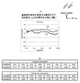
FIG. 52A to FIG. 52C are diagrams illustrating antenna characteristics according to the configuration disclosed in Japanese Patent Laid-Open No. 2002-151932.
52 (A) to 52 (C) are configurations in which an LC resonance circuit is provided in the middle of a power cord to limit the electrical length of the power cord in a high frequency manner, and broadcast waves are received at a portion where the electrical length is restricted. The antenna characteristics are shown.
FIG. 52A shows antenna gain characteristics in the UHF band. FIG. 52B is a diagram illustrating the vertical polarization property in the property diagram in FIG. FIG. 52C is a diagram illustrating the horizontal polarization property in the property diagram in FIG.
なお測定は、小型のテレビジョン受像機を想定したグランドサイズが300×300〔mm〕の評価基板を用いて、アンテナとして機能するケーブルを長さ1〔m〕に設定して測定した。
なお、図52(A)中の符号LHおよびLVは、それぞれ水平偏波および垂直偏波の特性を示している。
これら図52(A)〜図52(C)によれば、アンテナ利得の周期的な低下が見られ、広い周波数帯域で十分な利得により放送波を受信できないことが判る。
The measurement was performed using an evaluation board having a ground size of 300 × 300 [mm] assuming a small television receiver and setting a cable functioning as an antenna to a length of 1 [m].
Note that symbols LH and LV in FIG. 52A indicate characteristics of horizontal polarization and vertical polarization, respectively.
According to these FIGS. 52A to 52C, it can be seen that the antenna gain is periodically decreased, and that broadcast waves cannot be received with a sufficient gain in a wide frequency band.
これに対して、図53(A)〜図53(C)は、この第10の実施形態に係る電源ケーブル304のアンテナ特性の測定結果を示す図である。
図53(A)がUHF帯域のアンテナ利得特性を示す図である。図53(B)が図53(A)の特性図における垂直偏波の特性を示す図である。図53(C)が図53(A)の特性図における水平偏波の特性を示す図である。
これら図53(A)〜図53(C)によれば、全周波数帯域で約−5〔dB〕のアンテナ利得を確保でき、広い周波数帯域で十分な利得により放送波を受信できることが判る。 なお,測定の条件は、図42(A)〜図42(C)に示す測定結果と同一である。
On the other hand, FIGS. 53A to 53C are diagrams showing the measurement results of the antenna characteristics of the
FIG. 53A is a diagram showing antenna gain characteristics in the UHF band. 53B is a diagram illustrating the vertical polarization property in the property diagram in FIG. 53C is a diagram illustrating the horizontal polarization property in the property diagram in FIG.
53A to 53C, it can be seen that an antenna gain of about −5 [dB] can be secured in the entire frequency band, and broadcast waves can be received with a sufficient gain in a wide frequency band. Measurement conditions are the same as the measurement results shown in FIGS. 42 (A) to 42 (C).
〔第10の実施形態の効果〕
以上の構成によれば、電力伝送用ケーブルを利用してダイポールアンテナのエレメントを形成し、同軸ケーブルを介してテレビジョン受像機のアンテナ用コネクタに接続する。
これにより、第10の実施形態によれば、既存技術に比してアンテナに関する携帯性が向上し、広い周波数帯域で、十分な利得により放送波を受信することができるようになる。
[Effects of Tenth Embodiment]
According to the above configuration, the element of the dipole antenna is formed using the power transmission cable and connected to the antenna connector of the television receiver via the coaxial cable.
Thereby, according to the tenth embodiment, the portability of the antenna is improved as compared with the existing technology, and the broadcast wave can be received with a sufficient gain in a wide frequency band.
さらにこのエレメントに相当する部位のテレビジョン受像機側端およびプラグ側端に、それぞれ芯線ケーブルの高周波信号を抑圧するインダクタを設けることにより、芯線ケーブルによる特性の劣化を防止することができる。 Further, by providing an inductor that suppresses the high-frequency signal of the core cable at the television receiver side end and the plug side end of the portion corresponding to this element, it is possible to prevent deterioration of characteristics due to the core cable.
また、このインダクタを、電力伝送用ケーブルを挿通するフェライトコアにより形成することにより、簡易な構成により芯線ケーブルによる特性の劣化を防止することができる。 In addition, by forming the inductor with a ferrite core through which the power transmission cable is inserted, it is possible to prevent deterioration of characteristics due to the core wire cable with a simple configuration.
また、中継部に、芯線ケーブルの高周波信号を抑圧するインダクタを設けることにより、反共振による特性の劣化を防止することができる。 Further, by providing the relay unit with an inductor that suppresses the high-frequency signal of the core cable, it is possible to prevent deterioration of characteristics due to anti-resonance.
また、バランを介して同軸ケーブルである信号伝送用ケーブルに被覆線を接続することにより、テレビジョン受像機による特性の劣化を防止することができる。 In addition, by connecting a covered wire to a signal transmission cable that is a coaxial cable through a balun, it is possible to prevent deterioration of characteristics due to the television receiver.
また、被覆線のテレビジョン受像機側の部位と、プラグ側の部位とを異なる長さに設定することにより、一段と広い周波数帯域で十分な利得により放送波を受信することができる。 Also, by setting the length of the portion of the covered wire on the television receiver side and the portion on the plug side to different lengths, broadcast waves can be received with a sufficient gain in a wider frequency band.
<11.第11の実施形態>
図54は、図48の対比により、本第11の実施形態に係るテレビジョン受像機および電源ケーブルの要部の構成および接続関係を詳細に示す図である。
<11. Eleventh Embodiment>
FIG. 54 is a diagram showing in detail the configuration and connection relationships of the main parts of the television receiver and the power cable according to the eleventh embodiment, in comparison with FIG.
この電源ケーブル334は、中継部313に増幅回路335が設けられ、被覆線SSに誘起される高周波信号をこの増幅回路335で増幅して出力する。
なお、増幅回路335は、たとえば信号伝送用ケーブル312を介して電力が供給される。したがって、信号伝送用ケーブル312は、適宜、キャパシタ等の電力伝送に関する構成要素が設けられる。
電源ケーブル334は、この増幅回路に関する構成が異なる点を除いて、第10の実施形態の電源ケーブル304と同一に構成される。
The
The
The
この第11の実施形態では、中継部に増幅回路を設け、被覆線に誘起される高周波信号をこの増幅回路で増幅して出力することにより、一段とアンテナ利得を向上して第10の実施形態と同一の効果を得ることができる。 In the eleventh embodiment, an amplifier circuit is provided in the relay section, and a high frequency signal induced in the covered wire is amplified and output by the amplifier circuit, thereby further improving the antenna gain and the tenth embodiment. The same effect can be obtained.
<12.第12の実施形態>
図55は、図48の対比により、本第12の実施形態に係るテレビジョン受像機および電源ケーブルの要部の構成および接続関係を詳細に示す図である。
<12. Twelfth Embodiment>
FIG. 55 is a diagram showing in detail the configuration and connection relationships of the main parts of the television receiver and the power cable according to the twelfth embodiment, in comparison with FIG.
この電源ケーブル344は、テレビジョン受像機301側の被覆線SSのみバラン320を介して信号伝送用ケーブル312に接続される。
また、電源ケーブル344は、プラグ309側のフェライトコア318が省略される。電源ケーブル344は、このバラン320の接続に関する構成が異なる点を除いて、第10の実施形態の電源ケーブル304と同一に構成される。
なお、テレビジョン受像機301側の被覆線SSに代えて、プラグ309側の被覆線SSのみバラン320に接続してもよい。
The
The
Note that only the covered wire SS on the
この第12の実施形態では、テレビジョン受像機側の被覆線のみ、またはプラグ側の被覆線のみ信号伝送用ケーブルに接続するようにしても、第10の実施形態と同一の効果を得ることができる。 In the twelfth embodiment, the same effect as that of the tenth embodiment can be obtained even when only the covered wire on the television receiver side or only the covered wire on the plug side is connected to the signal transmission cable. it can.
<13.第13の実施形態>
図56は、図48の対比により、本第13の実施形態に係るテレビジョン受像機および電源ケーブルの要部の構成および接続関係を詳細に示す図である。
<13. Thirteenth Embodiment>
FIG. 56 is a diagram showing in detail the configuration and connection relationships of the main parts of the television receiver and the power cable according to the thirteenth embodiment, in comparison with FIG.
この電源コード354は、バラン320が省略され、直接、被覆線SSが信号伝送用ケーブル312に接続される。電源コード354は、このバラン320の接続に関する構成が異なる点を除いて、第10の実施形態の電源ケーブル304と同一に構成される。
In the
この第13の実施形態では、バランを省略することにより、構成を簡略化して第1の実施形態と同様の効果を得ることができる。 In the thirteenth embodiment, by omitting the balun, the configuration can be simplified and the same effects as those of the first embodiment can be obtained.
<14.第14の実施形態>
図57は、図48の対比により、本第14の実施形態に係るテレビジョン受像機および電源ケーブルの要部の構成および接続関係を詳細に示す図である。
<14. Fourteenth Embodiment>
FIG. 57 is a diagram showing in detail the configuration and connection relationships of the main parts of the television receiver and the power cable according to the fourteenth embodiment, in comparison with FIG.
この電源ケーブル364は、電源プラグ309側端、テレビジョン受像機301側端、中継部313のフェライトコア318、317、322が省略される。
電源ケーブル364は、これらフェライトコア318、317、322に関する構成が異なる点を除いて、第10の実施形態の電源ケーブル304と同一に構成される。
In the
The
この第14の実施形態では、フェライトコアを省略することにより、構成を簡略化して第1の実施形態と同様の効果を得ることができる。 In the fourteenth embodiment, by omitting the ferrite core, the configuration can be simplified and the same effect as in the first embodiment can be obtained.
<15.第15の実施形態>
図58は、図48の対比により、本第15の実施形態に係るテレビジョン受像機および電源ケーブルの要部の構成および接続関係を詳細に示す図である。
<15. Fifteenth embodiment>
FIG. 58 is a diagram showing in detail the configuration and connection relationships of the main parts of the television receiver and the power cable according to the fifteenth embodiment, in comparison with FIG.
この電源ケーブル374は、電力伝送用ケーブル311に代えて、電力伝送用ケーブル371が適用される。
電源ケーブル374は、この電力伝送用ケーブル371に関する構成が異なる点を除いて、第10の実施形態の電源ケーブル304と同一に構成される。
As the
The
図59は、第15の実施形態に係る図58の電力伝送用ケーブルの構造例示す簡略断面図である。 59 is a simplified cross-sectional view showing a structural example of the power transmission cable of FIG. 58 according to the fifteenth embodiment.
電力伝送用ケーブル371は、図59に断面をとって示すように、2本のケーブルL1およびL2を絶縁体372により覆って一体に保持する多芯ケーブルである。
電力伝送用ケーブル371は、この2本のケーブルL1およびL2が、商用電力の伝送に割り当てられ、それぞれ電源ジャック305、プラグ309の対応する端子に接続される。
The
In the
ケーブルL1およびL2は、電源ジャック305、プラグ309の付け根に、インダクタ317A、317Bおよびインダクタ318A、318Bが配置される。そして、それぞれ対応するインダクタ317A、317Bおよびインダクタ318A、318Bを介して電源ジャック305、プラグ309の対応する端子に接続される。
なお、インダクタ317A、317B、318A、318Bは、たとえばフェライトビーズにより構成されるものの、チップインダクタにより構成してもよく、さらには上述の実施形態と同様に、ケーブルL1およびL2に共通にフェライトコアを配置してもよい。
In the cables L1 and L2,
The
ケーブルL1およびL2は、インダクタ317A、317B、318A、318Bの中継部313側端がそれぞれキャパシタ375、376により接続され、高周波的に短絡状態に設定される。
また、ケーブルL1およびL2は、それぞれ中継部313にインダクタ322Aおよび322Bが配置され、このインダクタ322Aおよび322Bにより電源ジャック305側の部位と、プラグ309側の部位とに高周波的に分離される。
また、インダクタ322A、322Bの両端が、キャパシタ377、378により接続され、高周波的に短絡状態に設定される。
また、一方のケーブルL2に配置されたインダクタ322Bの両端がバラン320に接続される。
これにより、電力伝送用ケーブル371は、商用電力を伝送するケーブルL1およびL2が、電源ジャック305側の部位と、プラグ309側の部位とに高周波的に分離され、ダイポールアンテナのエレメントが構成される。
また、このエレメントをそれぞれチューナー332に接続して放送波を受信する。
なお、インダクタ322A、322Bにあっても、上述の実施形態と同様に、ケーブルL1およびL2に共通にフェライトコアを配置して作製してもよい。
In the cables L1 and L2, the
In addition, the cables L1 and L2 are respectively provided with
Further, both ends of the
Further, both ends of the
Thus, in the
Each element is connected to a
Even in the
この第15の実施形態によれば、商用電力を伝送するケーブルを高周波的に分離してダイポールアンテナのエレメントを構成するようにしても、第10の実施形態と同様の効果を得ることができる。 According to the fifteenth embodiment, the same effect as that of the tenth embodiment can be obtained even if the element for the dipole antenna is configured by separating the cable for transmitting commercial power in terms of high frequency.
<16.第16の実施形態>
この第16の実施形態は、商用電源から直流電力を生成する電源装置に本発明を適用する。
すなわち、この第16の実施形態の電源装置は、電源部で商用電源から直流電力を生成し、電源ケーブルを介してこの直流電力をコンピュータ等の本体装置に供給する。この電源装置は、この電源ケーブルに上述の各実施形態の構成が適用される。
<16. Sixteenth Embodiment>
In the sixteenth embodiment, the present invention is applied to a power supply device that generates DC power from a commercial power supply.
That is, the power supply device of the sixteenth embodiment generates DC power from a commercial power supply at the power supply unit, and supplies this DC power to a main unit such as a computer via a power cable. In this power supply device, the configurations of the above-described embodiments are applied to the power cable.
この実施形態によれば、本体装置に直流電源を供給する電源装置に適用しても、上述の各実施形態と同一の効果を得ることができる。 According to this embodiment, even if it is applied to a power supply device that supplies DC power to the main device, the same effects as those of the above-described embodiments can be obtained.
<17.第17の実施形態>
なお、上述の第10の実施形態等においては、電源ジャック5側端およびプラグ9側端に、それぞれインダクタを配置する場合について述べた。
しかしながら、本発明はこれに限らず、第17の実施形態として、たとえばインダクタを配置した箇所から電源伝送用のケーブルL1、L2をさらに延長させて電源ジャック305、プラグ309を配置してもよい。
この場合、電源コードの全長を種々の長さに設定することができる。
<17. Seventeenth Embodiment>
In the tenth embodiment and the like described above, the case where the inductors are arranged at the
However, the present invention is not limited to this, and as a seventeenth embodiment, for example, the power jacks 305 and the
In this case, the total length of the power cord can be set to various lengths.
また、上述の第10の実施形態等においては、フェライトコア317および中継部313間、中継部313およびフェライトコア318間に、被覆線SSを設ける場合について述べた。
しかしながら本発明はこれに限らず、フェライトコア317およびまたはフェライトコア318から中継部313側に一定の距離だけ離間した部位が、各被覆線SSのフェライトコア317、318側の端部となるように設定してもよい。
この場合、被覆線SSの長さに対して、対応する部位の芯線ケーブルの電気長を高周波的に長くすることができる。
したがって、さらに一段とアンテナの特性を広帯域化することができる。
In the tenth embodiment described above, the case where the covered wire SS is provided between the
However, the present invention is not limited to this, and a portion of the
In this case, with respect to the length of the covered wire SS, the electrical length of the corresponding core wire cable can be increased in terms of high frequency.
Therefore, the antenna characteristics can be further widened.
また、上述の第10の実施形態等においては、フェライトコアによるインダクタを配置する場合について述べた。
しかしながら本発明はこれに限らず、第15の実施形態と同様に、チップインダクタ等を個々のケーブルに配置してもよい。
In the tenth embodiment and the like described above, the case where an inductor with a ferrite core is arranged has been described.
However, the present invention is not limited to this, and chip inductors and the like may be arranged in individual cables as in the fifteenth embodiment.
また、上述の実施形態では、それぞれコネクタを介して着脱可能に電源コードをテレビジョン受像機に接続する場合について述べた。
しかしながら本発明はこれに限らず、いわゆる作り付けにより電源コードをテレビジョン受像機に接続する場合にも広く適用することができる。
Moreover, in the above-described embodiment, the case where the power cord is connected to the television receiver in a detachable manner via the connectors has been described.
However, the present invention is not limited to this, and can be widely applied to the case where the power cord is connected to the television receiver by so-called built-in.
また、上述の第15の実施形態では、インダクタ317A、317Bおよびインダクタ318A、318Bの中継部側端、インダクタ322A、322Bの両端をキャパシタで接続する場合について述べた。
しかしながら、実用上十分な特性を確保できる場合には、キャパシタ、インダクタを省略してもよい。
In the fifteenth embodiment described above, the case where the
However, when a practically sufficient characteristic can be secured, the capacitor and the inductor may be omitted.
また、上述の実施形態においては、同軸ケーブルを中継部に接続してケーブルに誘起された高周波信号をチューナーに入力する場合について述べた。
しかしながら本発明はこれに限らず、同軸ケーブルに代えて平行線ケーブルである平行線フィダーを適用してもよい。
In the above-described embodiment, the case where the coaxial cable is connected to the relay portion and the high frequency signal induced in the cable is input to the tuner has been described.
However, the present invention is not limited to this, and a parallel wire feeder that is a parallel wire cable may be applied instead of the coaxial cable.
また、上述の実施形態においては、コネクタのケーブル側にインダクタを設ける場合にについて述べた。
しかしながら本発明はこれに限らず、携帯電話の内部、電源装置の内部等にインダクタを設けるようにしてもよい。
In the above-described embodiment, the case where the inductor is provided on the cable side of the connector has been described.
However, the present invention is not limited to this, and an inductor may be provided in the mobile phone, the power supply device, or the like.
また、上述の実施形態においては、被覆線、電源伝送用のケーブルをそれぞれアンテナとして機能させる場合について述べた。
しかしながら本発明はこれに限らず、他の信号伝送用のケーブル、何ら信号、電力の伝送に使用していない空きのケーブルをアンテナとして機能させるようにしてもよい。
In the above-described embodiment, the case where the covered wire and the power transmission cable are each functioned as an antenna has been described.
However, the present invention is not limited to this, and another signal transmission cable, an empty cable that is not used for transmission of any signal or power may be caused to function as an antenna.
また、上述の実施形態では、それぞれ好適な構成を説明したが、本発明はこれらの構成に限らず、必要に応じて上述の構成を組み合わせてもよい。
具体的に、たとえば中継部から本体装置側には第10〜第14の実施形態を適用し、中継部からプラグ309側には第15の実施形態を適用するようにしてもよい。
Moreover, although the suitable structure was demonstrated in the above-mentioned embodiment, this invention is not restricted to these structures, You may combine the above-mentioned structure as needed.
Specifically, for example, the tenth to fourteenth embodiments may be applied from the relay unit to the main body device side, and the fifteenth embodiment may be applied from the relay unit to the
また、上述の実施形態においては、本発明をテレビジョン受像機に適用する場合について述べたが、本発明はこれに限らず、ビデオディスク装置、ラジオ等の各種受信装置、受信装置の電源コードに広く適用することができる。 In the above-described embodiment, the case where the present invention is applied to a television receiver has been described. However, the present invention is not limited to this, and various receiving devices such as a video disk device and a radio, and the power cord of the receiving device are used. Can be widely applied.
ところで、第10〜第17の実施形態においては、図60に示しように、ダイポールアンテナとして機能するように電源ケーブル(電源コード)を構成し、この電源ケーブルで放送波を受信する。
第10〜第17の実施形態においては、中継部313で電源ケーブル304を2分岐させるが、この中継部313は、図50に関連付けて説明したように、全体が樹脂でモールディングされる。
ところが、単にモールディングで固定した場合、形状が変形しやすくなりがちで、電源ケーブルの設置形状によってはアンテナ特性が変動してしまい、常に最適な特性を容易に得ることは難しいものと懸念される。
また、自動車等で、テレビジョン放送信号の受信を行うことを想定した場合、形状が変形し易いため、比較的電波環境の良いダッシュボード上に取り付けることが、非常に困難となるおそれがある。
そこで、以下には、アンテナ特性の変動を抑止可能なアンテナケーブルについて、第18〜第25の実施形態として説明する。
By the way, in 10th-17th embodiment, as shown in FIG. 60, a power cable (power cord) is comprised so that it may function as a dipole antenna, and a broadcast wave is received with this power cable.
In the tenth to seventeenth embodiments, the
However, the shape tends to be easily deformed when it is simply fixed by molding, and the antenna characteristic varies depending on the installation shape of the power cable, and there is a concern that it is difficult to always obtain the optimum characteristic easily.
Further, when it is assumed that a television broadcast signal is received in an automobile or the like, the shape is likely to be deformed, so that it may be very difficult to mount the dashboard on a dashboard having a relatively good radio wave environment.
Therefore, hereinafter, antenna cables capable of suppressing fluctuations in antenna characteristics will be described as 18th to 25th embodiments.
<18.第18の実施形態>
〔実施形態の構成〕
図61は、本発明の第18の実施形態に係る電子機器としてのテレビジョン受像機および電源ケーブルを含む受信装置を背面側から見て示す図である。
図62は、本第18の実施形態に係るテレビジョン受像機および電源ケーブルの要部の構成および接続関係を詳細に示す図である。
図63は、本第18の実施形態に係る基板部の実装構造例を示す図である。
なお、図63は、後で説明する第23の実施形態に係る多共振化用の構成が例示されている。
<18. Eighteenth Embodiment>
[Configuration of Embodiment]
FIG. 61 is a diagram showing a receiver including a television receiver and a power cable as an electronic apparatus according to an eighteenth embodiment of the present invention when viewed from the back side.
FIG. 62 is a diagram showing in detail the configuration and connection relationships of the main parts of the television receiver and the power cable according to the eighteenth embodiment.
FIG. 63 is a view showing a mounting structure example of the board portion according to the eighteenth embodiment.
FIG. 63 illustrates the configuration for multi-resonance according to a twenty-third embodiment which will be described later.
図61および図62の構成は、電源ケーブル404の中継部が、ダイポールアンテナを形成するケーブルの形状が変動し難いように、芯線を含む電力伝送ケーブルを固定することが可能な硬い素材の、電力伝送およびアンテナ用基板部413により形成されている。
61 and 62, the relay portion of the
電力伝送およびアンテナ用基板部413には、アンテナケーブルとしての機能を持つ電力伝送用ケーブル311の中間部において被覆線SSおよび外皮を剥離した、芯線を含むラインL11,L12が並行するように固定されている。
電力伝送およびアンテナ用基板部413には、バラン320が配置され、固定されている。
さらに、電力伝送およびアンテナ用基板部413において、ラインL11、L12には、高周波遮断部位としての機能するインダクタL421〜L423、L424〜L426が配置され、所望の周波数においてアンテナとして機能する構造が形成されている。
そして、基板部413より高周波用同軸ケーブルである信号伝送用ケーブル312を接続し、テレビジョン受像機101の受信端末のチューナー332にアンテナ構造にて、受信した信号を伝送する。
また、このアンテナケーブルにおいて、受信端末の音声回路と、イヤホン等の音声出力装置に接続され、音声信号を伝送するように構成することも可能である。
The power transmission and
A
Further, in the power transmission and
Then, a
Further, this antenna cable can be configured to be connected to an audio circuit of a receiving terminal and an audio output device such as an earphone to transmit an audio signal.
基板部413の外形は、使用周波数のλ/2以上の大きさがある。
基板部413の基板パターンは、直流的には、2本のラインL11,L12が形成されており、アンテナとして使用される帯域のλ/4の長さおきに高周波遮断用インダクタL421〜L423,L424〜L426が配置されている。
電源回路のグランドGNDに接続されるラインL12上にバラン320が接続されている。そして、インダクタL425によって高周波的に分断されているラインL12に、ダイポールアンテナを形成するように、それぞれのポートが接続されており、その反対側にアンテナ信号伝送用に信号伝送用同軸ケーブル312が接続されている。
The outer shape of the
As for the substrate pattern of the
A
基板部413に対して接続される電力伝送用ケーブル311−A,311−Bは、ラインL11が芯線として機能し、各被覆線SSに基板部413のラインL12の端部がそれぞれ接続されている。
そして、電力伝送用ケーブル311−Aの被覆線SSは、電源プラグ309に接続されている。また、電力伝送用ケーブル311−Bの被覆線SSは電源ジャック305に接続されている。
In the power transmission cables 311 -A and 311 -B connected to the
The covered wire SS of the power transmission cable 311 -A is connected to the
図64は、第18の実施形態に係るアンテナとしての原理を説明するための第1図である。
図65は、第18の実施形態に係るアンテナとしての原理を説明するための第2図である。
FIG. 64 is a first diagram for explaining the principle of the antenna according to the eighteenth embodiment.
FIG. 65 is a second diagram for explaining the principle of the antenna according to the eighteenth embodiment.
本例では、基板部413に設けた電力伝送ラインL11,L12をアンテナのエレメントとして利用しており、その長さは、図64に示すように、片側をλ/4として、バラン320を介してエレメントに給電することにより、ダイポールアンテナを形成している。
また、セットからの影響も軽減している。
また、インダクタL421〜L426のインピーダンスを調整することによって、図65に示すように、電力伝送用ケーブル311−A,311−Bもアンテナエレメントとして、使用することが可能となり、多共振に対応させることができる。
In this example, the power transmission lines L11 and L12 provided on the
Moreover, the influence from a set is also reduced.
Further, by adjusting the impedance of the inductors L421 to L426, as shown in FIG. 65, the power transmission cables 311-A and 311-B can also be used as antenna elements, so as to cope with multiple resonances. Can do.
図66(A)〜(C)は、基板部を有していない場合の電源ケーブルを真っ直ぐのばした状態(理想状態)のUHF帯域のアンテナ特性を示す図である。
図66(A)がUHF帯域のアンテナ利得特性を示す図である。図66(B)が図66(A)の特性図における垂直偏波の特性を示す図である。図66(C)が図66(A)の特性図における水平偏波の特性を示す図である。図66(A)において、横軸は周波数を示しており、縦軸はアンテナ利得を示している。
なお、図66(A)中の符号LHおよびLVは、それぞれ水平偏波および垂直偏波を示す
66 (A) to 66 (C) are diagrams showing antenna characteristics in the UHF band in a state where the power cable is straightened out (ideal state) when the board portion is not provided.
FIG. 66A shows antenna gain characteristics in the UHF band. 66B is a diagram illustrating the vertical polarization property in the property diagram in FIG. 66C is a diagram illustrating the horizontal polarization property in the property diagram in FIG. In FIG. 66 (A), the horizontal axis represents frequency and the vertical axis represents antenna gain.
Note that symbols LH and LV in FIG. 66A indicate horizontal polarization and vertical polarization, respectively.
また、図67(A)〜(C)は、基板部を有していない場合の電源ケーブルを半分折り畳んだ状態のUHF帯域のアンテナ特性を示す図である。
図67(A)がUHF帯域のアンテナ利得特性を示す図である。図67(B)が図67(A)の特性図における垂直偏波の特性を示す図である。図67(C)が図67(A)の特性図における水平偏波の特性を示す図である。図67(A)において、横軸は周波数を示しており、縦軸はアンテナ利得を示している。
67 (A) to 67 (C) are diagrams illustrating antenna characteristics in the UHF band in a state where the power supply cable is folded in half when the board portion is not provided.
FIG. 67A is a diagram illustrating antenna gain characteristics in the UHF band. 67B is a diagram illustrating the vertical polarization property in the property diagram in FIG. FIG. 67C is a diagram illustrating the horizontal polarization property in the property diagram in FIG. In FIG. 67A, the horizontal axis represents frequency and the vertical axis represents antenna gain.
図66(A)〜(C)に示すように、理想的なアンテナであるダイポールとの比較結果で、ピークゲインが高いほど良い特性であることを示している。
図67(A)〜(C)に示すように、ケーブルの形状を変形させることによってアンテナの主偏波が変わり、利得も劣化している。
As shown in FIGS. 66 (A) to 66 (C), the result of comparison with a dipole that is an ideal antenna indicates that the higher the peak gain, the better the characteristic.
As shown in FIGS. 67A to 67C, by changing the shape of the cable, the main polarization of the antenna changes and the gain also deteriorates.
図68(A)〜(C)は、基板部を有する第18の実施形態に係る電源ケーブルのUHF帯域のアンテナ特性を示す図である。
図68(A)がUHF帯域のアンテナ利得特性を示す図である。図68(B)が図68(A)の特性図における垂直偏波の特性を示す図である。図68(C)が図68(A)の特性図における水平偏波の特性を示す図である。図68(A)において、横軸は周波数を示しており、縦軸はアンテナ利得を示している。
FIGS. 68A to 68C are diagrams showing antenna characteristics in the UHF band of the power cable according to the eighteenth embodiment having a board portion.
FIG. 68A is a diagram showing antenna gain characteristics in the UHF band. 68B is a diagram illustrating the vertical polarization property in the property diagram in FIG. 68C is a diagram illustrating the horizontal polarization property in the property diagram in FIG. In FIG. 68A, the horizontal axis represents frequency and the vertical axis represents antenna gain.
本第18の実施形態においては、基板部413を用いることにより、形状が変化しないため、図68(A)〜(C)に示すように、特性の変動は非常に小さい。
In the eighteenth embodiment, since the shape does not change by using the
<19.第19の実施形態>
図69は、図62の対比により、本第19の実施形態に係るテレビジョン受像機および電源ケーブルの要部の構成および接続関係を詳細に示す図である。
<19. Nineteenth Embodiment>
FIG. 69 is a diagram showing in detail the configuration and connection relationships of the main parts of the television receiver and the power cable according to the nineteenth embodiment, in comparison with FIG.
この電源ケーブル414は、基板部413のバラン320が省略され、直接、被覆線SSが信号伝送用ケーブル312に接続される。電源ケーブル404は、このバラン320の接続に関する構成が異なる点を除いて、第18の実施形態の電源ケーブル404と同一に構成される。
In the
この第19の実施形態では、バランを省略することにより、コストダウンを図れ、構成を簡略化して第18の実施形態と同様の効果を得ることができる。 In the nineteenth embodiment, by omitting the balun, the cost can be reduced, the configuration can be simplified, and the same effects as in the eighteenth embodiment can be obtained.
<20.第20の実施形態>
図70は、図69の対比により、本第20の実施形態に係るテレビジョン受像機および電源ケーブルの要部の構成および接続関係を詳細に示す図である。
<20. 20th Embodiment>
FIG. 70 is a diagram showing in detail the configuration and connection relationships of the main parts of the television receiver and the power cable according to the twentieth embodiment, in comparison with FIG.
この電源ケーブル424は、基板部413に増幅回路435が設けられ、被覆線SSに誘起される高周波信号をこの増幅回路435で増幅して出力する。
なお、増幅回路435は、たとえば信号伝送用ケーブル312を介して電力が供給される。したがって、信号伝送用ケーブル312は、適宜、キャパシタ等の電力伝送に関する構成要素が設けられる。
電源ケーブル424は、この増幅回路に関する構成が異なる点を除いて、第19の実施形態の電源ケーブル414と同一に構成される。
The
The
The
この第20の実施形態では、基板部413に増幅回路435を設け、被覆線に誘起される高周波信号をこの増幅回路で増幅して出力することにより、一段とアンテナ利得を向上して第18および第19の実施形態と同一の効果を得ることができる。
In the twentieth embodiment, an
<21.第21の実施形態>
図71は、図69の対比により、本第21の実施形態に係るテレビジョン受像機および電源ケーブルの要部の構成および接続関係を詳細に示す図である。
<21. Twenty-first embodiment>
FIG. 71 is a diagram showing in detail the configuration and connection relationships of the main parts of the television receiver and the power cable according to the twenty-first embodiment, in comparison with FIG.
この電源ケーブル434は、基板部413にインダクタL421、L424を除去し、その代わりに、電力伝送用ケーブル311−Bと基板部413との間にフェライトコア417が配置されている。
電源ケーブル434は、一部のインダクタに代わりフェライトコアを配置する構成が異なる点を除いて、第19の実施形態の電源ケーブル414と同一に構成される。
In the
The
この第21の実施形態では、第18および第19の実施形態と同一の効果を得ることができる。 In the twenty-first embodiment, the same effects as in the eighteenth and nineteenth embodiments can be obtained.
<22.第22の実施形態>
図72は、図69の対比により、本第22の実施形態に係るテレビジョン受像機および電源ケーブルの要部の構成および接続関係を詳細に示す図である。
<22. Twenty-second embodiment>
FIG. 72 is a diagram showing in detail the configuration and connection relationships of the main parts of the television receiver and the power cable according to the twenty-second embodiment, in comparison with FIG.
この電源ケーブル444は、インダクタL427,L428を電力伝送用ケーブル311−A1,311−A2の中間にさらに設けることによって、多共振化を図った例である。
電源ケーブル444は、基板部413外で多共振化を図る構成が異なる点を除いて、第19の実施形態の電源ケーブル414と同一に構成される。
The
The
この第22の実施形態では、第18および第19の実施形態と同一の効果を得ることができる。 In the twenty- second embodiment, the same effects as in the eighteenth and nineteenth embodiments can be obtained.
<23.第23の実施形態>
図73は、図72の対比により、本第23の実施形態に係るテレビジョン受像機および電源ケーブルの要部の構成および接続関係を詳細に示す図である。
<23. Twenty-third embodiment>
FIG. 73 is a diagram showing in detail the configuration and connection relationships of the main parts of the television receiver and the power cable according to the twenty-third embodiment, in comparison with FIG.
この電源ケーブル454は、多共振化用の配置したインダクタL427、L428を除去し、その代わりに、フェライトコア418が配置されている。
電源ケーブル454は、一部のインダクタに代わりフェライトコアを配置する構成が異なる点を除いて、第22の実施形態の電源ケーブル444と同一に構成される。
In the
The
この第23の実施形態では、製造コスト削減を図れて、第18および第22の実施形態と同一の効果を得ることができる。 In the twenty-third embodiment, the manufacturing cost can be reduced, and the same effects as in the eighteenth and twenty-second embodiments can be obtained.
<24.第24の実施形態>
図74は、図73の対比により、本第24の実施形態に係るテレビジョン受像機および電源ケーブルの要部の構成および接続関係を詳細に示す図である。
<24. Twenty-fourth embodiment>
FIG. 74 is a diagram showing in detail the configuration and connection relationships of the main parts of the television receiver and the power cable according to the twenty-fourth embodiment, in comparison with FIG.
この電源ケーブル464は、多共振化用の配置したフェライトコアの代わりに、受信端末へ電源を供給するAC−DCまたはDC−DC変換する電源ユニット430が配置されている。
電源ケーブル464は、フェライトコアに代わり電源ユニットを配置する構成が異なる点を除いて、第23の実施形態の電源ケーブル454と同一に構成される。
In this
The
この第24の実施形態では、製造コスト削減を図れて、第18および第23の実施形態と同一の効果を得ることができる。 In the twenty-fourth embodiment, the manufacturing cost can be reduced, and the same effects as in the eighteenth and twenty-third embodiments can be obtained.
<25.第25の実施形態>
図75は、図69の対比により、本第25の実施形態に係るテレビジョン受像機および電源ケーブルの要部の構成および接続関係を詳細に示す図である。
<25. 25th Embodiment>
FIG. 75 is a diagram showing in detail the configuration and connection relationships of the main parts of the television receiver and the power cable according to the twenty-fifth embodiment, by comparison with FIG.
この電源ケーブル474は、基板部413にインダクタL422、L425のみを残し、インダクタL421,L424に代わりにフェライトコア427が配置され、インダクタL423,426の代わりにフェライトコア428が配置されている。
そして、ラインL11,L12、基板413、フェライトコア427,428を筐体500で押さえて形状の安定化が図られている。
電源ケーブル474は、一部のインダクタに代わりフェライトコアを配置して筐体で固定する構成が異なる点を除いて、第19の実施形態の電源ケーブル414と同一に構成される。
In the
The lines L11 and L12, the
The
この第25の実施形態では、アンテナ特性に変動を抑えて第18および第19の実施形態と同一の効果を得ることができる。 In the twenty-fifth embodiment, the same effects as those in the eighteenth and nineteenth embodiments can be obtained while suppressing fluctuations in antenna characteristics.
第18〜第25の実施形態によれば、アンテナケーブルとして機能する電源ケーブルのアンテナエレメント形状を基板部などで固定することで、アンテナ利得向上を図り、ユーザーに明確にアンテナ箇所を伝達することが可能となる。
その結果、比較的電波環境の良好な場所へ設置を促すことで、受信端末の携帯性・利便性を高めることが可能となる。
According to the eighteenth to twenty-fifth embodiments, by fixing the antenna element shape of the power cable functioning as an antenna cable with the substrate portion or the like, the antenna gain can be improved and the antenna location can be clearly transmitted to the user. It becomes possible.
As a result, it is possible to improve the portability and convenience of the receiving terminal by prompting installation in a place with a relatively good radio wave environment.
1,41,51,61,71,81,91,101……受信システム、2,42……携帯電話、3,43,43,63,73,83……電源装置、4,44,64……電力伝送用ケーブル、6,76……電源部、5,7……コネクタ、17L,17G,18L,18G……インダクタ、14……チューナー、74……フェライトコア、301……テレビジョン受像機、302,309……プラグ、303……アンテナ用コネクタ、304,334,344,354,364,374……電源ケーブル、305……電源ジャック、306……高周波コネクタ、311,371……電力伝送用ケーブル、312……信号伝送用ケーブル、313……中継部、320……バラン、331……電源回路、332……チューナー、404,414,424,434,444,454,464,474……電源ケーブル、413……基板部、L421〜L428……インダクタ、L11,L12……ライン。 1, 41, 51, 61, 71, 81, 91, 101... Reception system, 2, 42 ... mobile phone, 3, 43, 43, 63, 73, 83 ... power supply, 4, 44, 64 ... ... Power transmission cable, 6,76 ... Power supply, 5,7 ... Connector, 17L, 17G, 18L, 18G ... Inductor, 14 ... Tuner, 74 ... Ferrite core, 301 ... Television receiver , 302, 309... Plug, 303... Antenna connector, 304, 334, 344, 354, 364, 374 ... Power cable, 305 ... Power jack, 306 ... High frequency connector, 311, 371 ... Power transmission Cable, 312... Signal transmission cable, 313 .. relay unit, 320... Balun, 331... Power supply circuit, 332. , 434,444,454,464,474 ...... power cable, 413 ...... substrate portion, L421~L428 ...... inductor, L11, L12 ...... line.
Claims (34)
前記電源部から出力される電力を、本体装置にコネクタを介して供給する電力伝送用ケーブルと、を有し、
前記電力伝送用ケーブルは、
前記コネクタの電源端子との間に配置された本体装置側高周波遮断部と、
前記コネクタから所定長さだけ前記電源部側に配置され、アンテナとして機能する部位の長さを制限する電源部側高周波遮断部と、
前記本体装置側高周波遮断部を介して前記本体装置への電力供給をするための第1伝送線と、
前記コネクタを介して前記本体装置のチューナーに接続される第2伝送線と、
を含む
電源装置。 A power supply for outputting the power of the main unit,
A power transmission cable for supplying power output from the power supply unit to the main unit via a connector;
The power transmission cable is
A main unit side high-frequency cutoff part disposed between the power supply terminals of the connector;
A predetermined length from the connector is arranged on the power supply unit side, and the power supply unit side high frequency cutoff unit that limits the length of the part that functions as an antenna;
A first transmission line for supplying power to the main unit through the main unit side high-frequency cutoff unit;
A second transmission line connected to the tuner of the main unit via the connector;
Including power supply.
前記第1伝送線と対になって前記本体装置側高周波遮断部を介して前記電力供給をするための伝送線を兼ねる
請求項1に記載の電源装置。 The second transmission line is
The power supply device according to claim 1, wherein the power supply device also serves as a transmission line for paired with the first transmission line and for supplying the power via the main device side high-frequency cutoff unit.
前記第1伝送線としての複数の芯線と、前記複数の芯線を被覆する被覆線と、を有する多芯同軸ケーブルにより形成され、
前記被覆線は、
前記電源部側端が開放端であり、前記第2伝送線として前記チューナーに接続される
請求項1に記載の電源装置。 The power transmission cable is
Formed by a multi-core coaxial cable having a plurality of core wires as the first transmission line and a covered wire covering the plurality of core wires;
The covered wire is
The power supply device according to claim 1, wherein the power supply unit side end is an open end, and is connected to the tuner as the second transmission line.
前記チューナーで受信する基本周波数の波長に対して1/4波長の奇数倍の長さに設定され、
前記チューナーは、
前記基本周波数の帯域および前記基本周波数の高調波の帯域を受信する
請求項1から3のいずれか一に記載の電源装置。 The predetermined length is
It is set to an odd multiple of a quarter wavelength with respect to the wavelength of the fundamental frequency received by the tuner,
The tuner is
The power supply device according to any one of claims 1 to 3, wherein the power supply device receives a band of the fundamental frequency and a harmonic band of the fundamental frequency.
前記伝送ケーブルにそれぞれインダクタを介挿して形成されている
請求項1から4のいずれか一に記載の電源装置。 The high-frequency cutoff unit on the power source side is
The power supply device according to claim 1, wherein each of the transmission cables is formed with an inductor interposed therebetween.
フェライトコアに前記電力伝送用ケーブルを挿通して形成されている
請求項1から4のいずれか一に記載の電源装置。 The high-frequency cutoff unit on the power source side is
The power supply device according to claim 1, wherein the power transmission cable is inserted into a ferrite core.
請求項1から6のいずれか一に記載の電源装置。 The power supply device according to any one of claims 1 to 6, wherein an amplifier circuit that amplifies a high-frequency signal induced in a portion that functions as the antenna is disposed in the connector.
前記コネクタを介して前記本体装置に接続され、前記本体装置の電力を前記本体装置に供給する前記電源装置と、を有し、
前記電源装置は、
本体装置の電力を出力する電源部と、
一端に配置されたコネクタを介して、前記電源部から出力される電力を本体装置に伝送する電力伝送用ケーブルと、を含み、
前記電力伝送用ケーブルは、
前記コネクタの電源端子を介して本体装置に接続され、前記本体装置の電力を伝送する複数の伝送ケーブルを有し、
前記複数の伝送ケーブルは、
それぞれ対応する前記電源端子との間に、本体装置側の高周波遮断部が配置され、
前記電力伝送用ケーブルは、
前記コネクタから所定長さだけ前記電源部側に、アンテナとして機能する部位の長さを制限する電源部側の高周波遮断部が配置され、
前記伝送ケーブルの少なくとも1つが、前記コネクタを介して前記本体装置のチューナーに接続される
受信装置。 A main unit having a connector for connecting a power supply device and receiving a desired broadcast wave by a built-in tuner;
The power supply device connected to the main body device via the connector and supplying power of the main body device to the main body device;
The power supply device
A power supply for outputting the power of the main unit,
A power transmission cable for transmitting the power output from the power supply unit to the main unit through a connector disposed at one end;
The power transmission cable is
A plurality of transmission cables connected to the main unit through the power terminal of the connector and transmitting the power of the main unit;
The plurality of transmission cables are:
Between the corresponding power supply terminals, a high-frequency cutoff unit on the main device side is disposed,
The power transmission cable is
A high-frequency cutoff unit on the power source side that limits the length of the portion that functions as an antenna is disposed on the power source side by a predetermined length from the connector,
A receiving device, wherein at least one of the transmission cables is connected to a tuner of the main device through the connector.
前記コネクタの電源端子を介して前記本体装置に接続され、前記本体装置の電力を伝送する複数の芯線ケーブルと、前記芯線ケーブルを被覆する被覆線と、を有する多芯同軸ケーブルにより形成され、
前記芯線ケーブルは、
それぞれ対応する前記電源端子との間に、本体装置側の高周波遮断部が配置され、
前記電力伝送用ケーブルは、
前記コネクタから所定長さだけ前記電源部側に、アンテナとして機能する部位の長さを制限する電源部側の高周波遮断部が設けられ、
前記被覆線は、
前記電源部側の高周波遮断部側端が開放端とされ、前記コネクタを介して前記本体装
置の前記チューナーに接続される
請求項8に記載の受信装置。 The power transmission cable is
A plurality of core cables that are connected to the main unit via the power supply terminal of the connector and transmit power of the main unit, and a multi-core coaxial cable having a covered wire that covers the core cable;
The core cable is
Between the corresponding power supply terminals, a high-frequency cutoff unit on the main device side is disposed,
The power transmission cable is
A high-frequency cutoff part on the power supply part side that limits the length of the part that functions as an antenna is provided on the power supply part side by a predetermined length from the connector,
The covered wire is
The receiving device according to claim 8, wherein the high-frequency cutoff unit side end on the power supply unit side is an open end, and is connected to the tuner of the main body device via the connector.
前記電力伝送用ケーブルの一端側に配置され、前記電力伝送用ケーブルを前記本体装置に接続する本体装置側コネクタと、
前記電力伝送用ケーブルの他端側に配置され、前記電力伝送用ケーブルを前記外部装置に接続する外部装置側コネクタと、を有し、
前記電力伝送用ケーブルは、
前記本体装置側コネクタの電源端子を介して本体装置に接続され、前記本体装置の電力を伝送する複数の伝送ケーブルを有し、
前記複数の伝送ケーブルは、
それぞれ対応する前記電源端子との間に、本体装置側の高周波遮断部が配置され、
前記電力伝送用ケーブルは、
前記本体装置側のコネクタから所定長さだけ前記外部装置側に、アンテナとして機能する部位の長さを制限する外部装置側の高周波遮断部が配置され、
前記伝送用ケーブルの少なくとも1つが、前記本体装置側のコネクタを介して前記本体装置に内蔵のチューナーのアンテナ入力端に接続される
電源ケーブル。 A power transmission cable for transmitting power between the main unit and the external device;
A main unit side connector that is disposed on one end side of the power transmission cable and connects the power transmission cable to the main unit;
An external device-side connector that is disposed on the other end side of the power transmission cable and connects the power transmission cable to the external device;
The power transmission cable is
Connected to the main unit through the power supply terminal of the main unit side connector, and has a plurality of transmission cables for transmitting the power of the main unit,
The plurality of transmission cables are:
Between the corresponding power supply terminals, a high-frequency cutoff unit on the main device side is disposed,
The power transmission cable is
On the external device side by a predetermined length from the connector on the main device side, a high-frequency cutoff unit on the external device side that restricts the length of the part that functions as an antenna is disposed,
A power cable in which at least one of the transmission cables is connected to an antenna input end of a tuner built in the main unit through a connector on the main unit.
前記本体装置側のコネクタの電源端子を介して前記本体装置に接続され、前記本体装置の電力を伝送する複数の芯線ケーブルと、前記芯線ケーブルを被覆する被覆線とを有する多芯同軸ケーブルにより形成され、
前記芯線ケーブルは、
それぞれ対応する前記電源端子との間に、本体装置側の高周波遮断部が配置され、
前記電力伝送用ケーブルは、
前記本体装置側のコネクタから所定長さだけ前記外部装置側に、アンテナとして機能する部位の長さを制限する外部装置側の高周波遮断部が配置され、
前記被覆線は、
前記外部装置側の高周波遮断部側端が開放端とされ、前記本体装置側のコネクタを介して前記本体装置に内蔵のチューナーに接続される
請求項10記載の電源ケーブル。 The power transmission cable is
Formed by a multi-core coaxial cable that is connected to the main body device via a power supply terminal of the main body device-side connector and has a plurality of core wire cables that transmit power of the main body device and a covered wire that covers the core wire cable And
The core cable is
Between the corresponding power supply terminals, a high-frequency cutoff unit on the main device side is disposed,
The power transmission cable is
On the external device side by a predetermined length from the connector on the main device side, a high-frequency cutoff unit on the external device side that restricts the length of the part that functions as an antenna is disposed,
The covered wire is
The power cable according to claim 10, wherein the external device side high-frequency cutoff unit side end is an open end, and is connected to a tuner built in the main body device via a connector on the main body device side.
放送波を受信する内蔵のチューナーと、を有し、
前記電源ケーブルは、
前記電力を伝送する複数の伝送ケーブルを含む電力伝送用ケーブルを有し、
前記電力伝送用ケーブルに含まれる前記伝送ケーブルの少なくとも1つは、
途中の中継部で、第1の部位と、第2の部位とに高周波的に分離され、
前記第1の部位の前記中継部側とは逆側、および前記第2の部位の前記中継部側とは逆側が高周波的に他の部位と絶縁され、
前記第1の部位の前記中継部側、および前記第2の部位の前記中継部側の少なくとも1つが、同軸ケーブルまたは平行線ケーブルを介して前記チューナーに接続される
受信装置。 A power cable for supplying power;
A built-in tuner for receiving broadcast waves, and
The power cable is
A power transmission cable including a plurality of transmission cables for transmitting the power;
At least one of the transmission cables included in the power transmission cable is:
In the intermediate relay part, the first part and the second part are separated in high frequency,
The side opposite to the relay part side of the first part and the side opposite to the relay part side of the second part are insulated from other parts in high frequency,
At least one of the first part on the relay part side and the second part on the relay part side is connected to the tuner via a coaxial cable or a parallel line cable.
前記第1の部位の前記中継部側とは逆側、および前記第2の部位の前記中継部側とは逆側に、高周波信号を抑圧するインダクタが配置され、
前記インダクタにより、前記第1の部位の前記中継部側とは逆側、および前記第2の部位の前記中継部側とは逆側が高周波的に他の部位と絶縁されている
請求項12に記載の受信装置。 The power transmission cable is
An inductor that suppresses a high-frequency signal is disposed on the side opposite to the relay part side of the first part and the side opposite to the relay part side of the second part,
The high frequency side of the first part opposite to the relay part side and the opposite side of the second part to the relay part side are insulated from other parts at high frequency by the inductor. Receiver.
前記中継部に、高周波信号を抑圧するインダクタが配置され、
前記インダクタにより、第1の部位と、第2の部位とに高周波的に分離される
請求項12に記載の受信装置。 The power transmission cable is
An inductor for suppressing a high-frequency signal is disposed in the relay unit,
The receiving device according to claim 12, wherein the inductor is separated into a first part and a second part by high frequency.
請求項12から14のいずれか一に記載の受信装置。 The at least one of the first part on the relay part side and the second part on the relay part side is connected to the coaxial cable or parallel line cable via a balun. A receiving device according to claim 1.
放送波を受信する内蔵のチューナーと、を有し、
前記電源ケーブルは、
前記電力を伝送する複数の芯線ケーブルと、前記複数の芯線ケーブルを被覆する被覆線とを含む電力伝送用ケーブルを有し、
前記被覆線は、
前記電力伝送用ケーブルの途中の中継部で、第1の部位と、第2の部位とに分離され、
前記第1の部位の前記中継部側とは逆側、および前記第2の部位の前記中継部側とは逆側が開放端に設定され、
前記第1の部位の前記中継部側、および前記第2の部位の前記中継部側の少なくとも1つが、同軸ケーブルまたは平行線ケーブルを介して前記チューナーに接続される
受信装置。 A power cable for supplying power;
A built-in tuner for receiving broadcast waves, and
The power cable is
A power transmission cable including a plurality of core wire cables for transmitting the power and a covered wire covering the plurality of core wire cables;
The covered wire is
In the relay part in the middle of the power transmission cable, it is separated into a first part and a second part,
The side opposite to the relay part side of the first part and the side opposite to the relay part side of the second part are set as open ends,
At least one of the first part on the relay part side and the second part on the relay part side is connected to the tuner via a coaxial cable or a parallel line cable.
前記第1の部位の前記中継部側とは逆側、および前記第2の部位の前記中継部側とは逆側に、前記芯線ケーブルの高周波信号を抑圧するインダクタが配置されている
請求項16に記載の受信装置。 The power transmission cable is
17. An inductor that suppresses a high-frequency signal of the core cable is disposed on a side opposite to the relay part side of the first part and on a side opposite to the relay part side of the second part. The receiving device described in 1.
前記中継部に、前記芯線ケーブルの高周波信号を抑圧するインダクタが配置されている
請求項16に記載の受信装置。 The power transmission cable is
The receiving device according to claim 16, wherein an inductor that suppresses a high-frequency signal of the core cable is disposed in the relay unit.
請求項16から18のいずれか一に記載の受信装置。 The receiving device according to any one of claims 16 to 18, wherein the covered wire is connected to the coaxial cable or the parallel cable via a balun.
前記電力伝送用ケーブルを挿通するフェライトコアにより形成された
請求項13、14、15、17,18、または19に記載の受信装置。 The inductor is
The receiving device according to claim 13, formed by a ferrite core that passes through the power transmission cable.
前記第1の部位と、前記第2の部位とが、異なる長さに設定された
請求項12から20のいずれか一に記載の受信装置。 The covered wire is
The receiving device according to any one of claims 12 to 20, wherein the first part and the second part are set to have different lengths.
放送波を受信する内蔵のチューナーと、を有し、
前記電源ケーブルは、
前記電力を伝送する第1のケーブルおよび第2のケーブルを含み、
前記第1のケーブルおよび第2のケーブルの少なくとも1つは、
途中の中継部で、第1の部位と第2の部位とに高周波的に分離され、
前記第1の部位の前記中継部側、および前記第2の部位の前記中継部側の少なくとも1つが、同軸ケーブルまたは平行線ケーブルを介して前記チューナーに接続される
受信装置。 A power cable for supplying power;
A built-in tuner for receiving broadcast waves, and
The power cable is
Including a first cable and a second cable for transmitting the power;
At least one of the first cable and the second cable is:
In the intermediate relay part, the first part and the second part are separated in high frequency,
At least one of the first part on the relay part side and the second part on the relay part side is connected to the tuner via a coaxial cable or a parallel line cable.
前記電力伝送用ケーブルに含まれる複数の伝送ケーブルの少なくとも1つは、
途中の中継部で、第1の部位と、第2の部位とに高周波的に分離され、
前記第1の部位の前記中継部側とは逆側、および前記第2の部位の前記中継部側とは逆側が高周波的に他の部位と絶縁され、
前記第1の部位の前記中継部側、および前記第2の部位の前記中継部側の少なくとも1つが、同軸ケーブルまたは平行線ケーブルを介して前記本体装置のチューナーに接続される
電源ケーブル。 A power transmission cable including a plurality of transmission cables for transmitting power to the main unit;
At least one of the plurality of transmission cables included in the power transmission cable is:
In the intermediate relay part, the first part and the second part are separated in high frequency,
The side opposite to the relay part side of the first part and the side opposite to the relay part side of the second part are insulated from other parts in high frequency,
A power cable in which at least one of the first part on the relay part side and the second part on the relay part side is connected to the tuner of the main body device via a coaxial cable or a parallel cable.
前記被覆線は、
前記電力伝送用ケーブルの途中の中継部で、第1の部位と、前記第2の部位とに分離され、
前記第1の部位の前記中継部側とは逆側、および前記第2の部位の前記中継部側とは逆側が開放端に形成され、
前記第1の部位の前記中継部側、および前記第2の部位の前記中継部側の少なくとも1つが、同軸ケーブルまたは平行線ケーブルを介して前記本体装置のチューナーに接続される
電源ケーブル。 A power transmission cable including a plurality of core cables for transmitting power to the main unit and a coated wire covering the plurality of core cables;
The covered wire is
In the relay part in the middle of the power transmission cable, it is separated into a first part and the second part,
The side opposite to the relay part side of the first part and the side opposite to the relay part side of the second part are formed at the open end,
A power cable in which at least one of the first part on the relay part side and the second part on the relay part side is connected to the tuner of the main body device via a coaxial cable or a parallel cable.
第1および第2のケーブルの少なくとも1つは、
途中の中継部で、第1の部位と第2の部位とに高周波的に分離され、
前記第1の部位の前記中継部側、および前記第2の部位の前記中継部側の少なくとも1つが、同軸ケーブルまたは平行線ケーブルを介して前記本体装置のチューナーに接続される
電源ケーブル。 Having first and second cables for transmitting power to the main unit;
At least one of the first and second cables is
In the intermediate relay part, the first part and the second part are separated in high frequency,
A power cable in which at least one of the first part on the relay part side and the second part on the relay part side is connected to the tuner of the main body device via a coaxial cable or a parallel cable.
前記電源部の電力を前記本体装置に伝送する複数の伝送ケーブルを含む電力伝送用ケーブルと、を有し、
前記電力伝送用ケーブルに含まれる複数のケーブルの少なくとも1つは、
途中の中継部で、第1の部位と、第2の部位とに高周波的に分離され、
前記第1の部位の前記中継部側とは逆側、および前記第2の部位の前記中継部側とは逆側が高周波的に他の部位と絶縁され、
前記第1の部位の前記中継部側、および前記第2の部位の前記中継部側の少なくとも1つが、同軸ケーブルまたは平行線ケーブルを介して前記本体装置のチューナーに接続される
電源装置。 A power supply unit that generates power for the main unit,
A power transmission cable including a plurality of transmission cables for transmitting the power of the power supply unit to the main unit,
At least one of the plurality of cables included in the power transmission cable is:
In the intermediate relay part , the first part and the second part are separated in high frequency,
The side opposite to the relay part side of the first part and the side opposite to the relay part side of the second part are insulated from other parts in high frequency,
At least one of the first part on the relay part side and the second part on the relay part side is connected to a tuner of the main body device via a coaxial cable or a parallel line cable.
前記電源部の電力源を前記本体装置に伝送する複数の芯線ケーブルと、前記複数の芯線ケーブルを被覆する被覆線とを含む電力伝送用ケーブルを有し、
前記被覆線は、
前記電力伝送用ケーブルの途中の中継部で、第1の部位と、第2の部位とに分離され、 前記第1の部位の前記中継部側とは逆側、および前記第2の部位の前記中継部側とは逆側が開放端に形成され、
前記第1の部位の前記中継部側、および前記第2の部位の前記中継部側の少なくとも1つが、同軸ケーブルまたは平行線ケーブルを介して前記本体装置のチューナーに接続される
電源装置。 A power supply unit that generates power for the main unit,
A power transmission cable including a plurality of core cables for transmitting a power source of the power supply unit to the main body device, and a covered wire covering the plurality of core cables;
The covered wire is
The relay part in the middle of the power transmission cable is separated into a first part and a second part, the opposite side of the first part to the relay part side, and the second part The opposite side to the relay part side is formed at the open end,
At least one of the first part on the relay part side and the second part on the relay part side is connected to a tuner of the main body device via a coaxial cable or a parallel line cable.
前記電源部の電力を前記本体装置に伝送する第1のケーブルおよび第2のケーブルを有し、
第1のケーブルおよび第2のケーブルの少なくとも1つは、
途中の中継部で、第1の部位と第2の部位とに高周波的に分離され、
前記第1の部位の前記中継部側、および前記第2の部位の前記中継部側の少なくとも1つが、同軸ケーブルまたは平行線ケーブルを介して前記本体装置のチューナーに接続される
電源装置。 A power supply unit that generates power for the main unit,
A first cable and a second cable for transmitting the power of the power supply unit to the main unit;
At least one of the first cable and the second cable is:
In the intermediate relay part, the first part and the second part are separated in high frequency,
At least one of the first part on the relay part side and the second part on the relay part side is connected to a tuner of the main body device via a coaxial cable or a parallel line cable.
前記電力伝送用ケーブルの中間部において、前記複数の伝送ケーブルを固定するように配置された基板部と、を有し、
前記基板部は、
前記伝送ケーブルに高周波遮断部が配置され、
前記高周波遮断部で高周波的に遮断された前記伝送ケーブルの一つが、ダイポールアンテナを形成するように同軸ケーブルまたは平行線ケーブルを介して前記本体装置のチューナーに接続される
電源ケーブル。 A power transmission cable including a plurality of transmission cables for transmitting power to the main unit;
A substrate portion disposed so as to fix the plurality of transmission cables in an intermediate portion of the power transmission cable;
The substrate portion is
A high-frequency cutoff unit is disposed in the transmission cable,
One of the transmission cables cut off at a high frequency by the high frequency cut-off unit is connected to a tuner of the main unit via a coaxial cable or a parallel line cable so as to form a dipole antenna.
前記基板の長さが使用周波数のλ/2以上の長さを有する
請求項29記載の電源ケーブル。 The substrate portion is
30. The power cable according to claim 29, wherein the length of the substrate has a length of [lambda] / 2 or more of a use frequency.
基板実装されたバランを介して前記同軸ケーブルまたは平行線ケーブルに接続されている
請求項29または30記載の電源ケーブル。 The substrate portion is
The power cable according to claim 29 or 30, wherein the power cable is connected to the coaxial cable or parallel line cable via a balun mounted on a board.
アンテナとして使用される帯域のλ/4の長さおきに前記高周波遮断部が配置されている
請求項29から31のいずれか一に記載の電源ケーブル。 The substrate portion is
The power cable according to any one of claims 29 to 31, wherein the high-frequency cutoff unit is arranged at every λ / 4 length of a band used as an antenna.
前記電源部の電力を前記本体装置に伝送する複数の伝送ケーブルを含む電力伝送用ケーブルと、
前記電力伝送用ケーブルの中間部において、前記複数の伝送ケーブルを固定するように配置された基板部と、を有し、
前記基板部は、
前記伝送ケーブルに高周波遮断部が配置され、
前記高周波遮断部で高周波的に遮断された前記伝送ケーブルの一つが、ダイポールアンテナを形成するように同軸ケーブルまたは平行線ケーブルを介して前記本体装置のチューナーに接続される
電源装置。 A power supply unit that generates power for the main unit,
A power transmission cable including a plurality of transmission cables for transmitting the power of the power supply unit to the main unit;
A substrate portion disposed so as to fix the plurality of transmission cables in an intermediate portion of the power transmission cable;
The substrate portion is
A high-frequency cutoff unit is disposed in the transmission cable,
One of the transmission cables cut off at a high frequency by the high frequency cut-off unit is connected to a tuner of the main unit through a coaxial cable or a parallel line cable so as to form a dipole antenna.
放送波を受信する内蔵のチューナーと、を有し、
前記電源ケーブルは、
前記電源部の電力を前記本体装置に伝送する複数の伝送ケーブルを含む電力伝送用ケーブルと、
前記電力伝送用ケーブルの中間部において、前記複数の伝送ケーブルを固定するように配置された基板部と、を有し、
前記基板部は、
前記伝送ケーブルに高周波遮断部が配置され、
前記高周波遮断部で高周波的に遮断された前記伝送ケーブルの一つが、ダイポールアンテナを形成するように同軸ケーブルまたは平行線ケーブルを介して前記本体装置のチューナーに接続される
受信装置。 A power cable for supplying power;
A built-in tuner for receiving broadcast waves, and
The power cable is
A power transmission cable including a plurality of transmission cables for transmitting the power of the power supply unit to the main unit;
A substrate portion disposed so as to fix the plurality of transmission cables in an intermediate portion of the power transmission cable;
The substrate portion is
A high-frequency cutoff unit is disposed in the transmission cable,
One of the transmission cables cut off at a high frequency by the high frequency cut-off unit is connected to a tuner of the main unit through a coaxial cable or a parallel line cable so as to form a dipole antenna.
Priority Applications (5)
| Application Number | Priority Date | Filing Date | Title |
|---|---|---|---|
| JP2009223406A JP5402471B2 (en) | 2008-12-05 | 2009-09-28 | Power supply, power cable, and receiver |
| CN200910252737.1A CN101752661A (en) | 2008-12-05 | 2009-12-04 | Power supply device, power cable and reception device |
| EP09252738A EP2194601A3 (en) | 2008-12-05 | 2009-12-04 | Power supply device, power cable and reception device |
| BRPI0906562-8A BRPI0906562A2 (en) | 2008-12-05 | 2009-12-04 | power supply device, receiving device, and power cord |
| US12/631,186 US8391816B2 (en) | 2008-12-05 | 2009-12-04 | Power supply device, power cable, and reception device |
Applications Claiming Priority (5)
| Application Number | Priority Date | Filing Date | Title |
|---|---|---|---|
| JP2008310840 | 2008-12-05 | ||
| JP2008310695 | 2008-12-05 | ||
| JP2008310695 | 2008-12-05 | ||
| JP2008310840 | 2008-12-05 | ||
| JP2009223406A JP5402471B2 (en) | 2008-12-05 | 2009-09-28 | Power supply, power cable, and receiver |
Publications (3)
| Publication Number | Publication Date |
|---|---|
| JP2010157991A JP2010157991A (en) | 2010-07-15 |
| JP2010157991A5 JP2010157991A5 (en) | 2012-11-01 |
| JP5402471B2 true JP5402471B2 (en) | 2014-01-29 |
Family
ID=41697887
Family Applications (1)
| Application Number | Title | Priority Date | Filing Date |
|---|---|---|---|
| JP2009223406A Expired - Fee Related JP5402471B2 (en) | 2008-12-05 | 2009-09-28 | Power supply, power cable, and receiver |
Country Status (5)
| Country | Link |
|---|---|
| US (1) | US8391816B2 (en) |
| EP (1) | EP2194601A3 (en) |
| JP (1) | JP5402471B2 (en) |
| CN (1) | CN101752661A (en) |
| BR (1) | BRPI0906562A2 (en) |
Cited By (1)
| Publication number | Priority date | Publication date | Assignee | Title |
|---|---|---|---|---|
| KR102076761B1 (en) * | 2018-11-26 | 2020-02-12 | 한양대학교 산학협력단 | Dual-band cable antenna apparatus |
Families Citing this family (15)
| Publication number | Priority date | Publication date | Assignee | Title |
|---|---|---|---|---|
| US8075342B1 (en) * | 2008-09-03 | 2011-12-13 | R&M Tone Technology | Amplifying connector |
| WO2010134538A1 (en) * | 2009-05-20 | 2010-11-25 | ソニー株式会社 | Antenna device |
| AU2010318464B2 (en) | 2009-11-13 | 2015-07-09 | Panasonic Intellectual Property Corporation Of America | Encoding method, decoding method, coder and decoder |
| JP5799852B2 (en) | 2011-03-30 | 2015-10-28 | ソニー株式会社 | I / O device |
| JP5834487B2 (en) | 2011-05-18 | 2015-12-24 | ソニー株式会社 | USB cable antenna |
| WO2013109247A1 (en) * | 2012-01-17 | 2013-07-25 | Thomson Licensing | Rf remote control power cable antenna |
| JP5803896B2 (en) | 2012-02-23 | 2015-11-04 | ソニー株式会社 | I / O device |
| EP2874232B1 (en) * | 2012-07-13 | 2020-11-04 | Sony Corporation | Antenna |
| US20150303549A1 (en) * | 2014-04-22 | 2015-10-22 | Apple Inc. | Electronic Device Connector Structures With Antennas |
| JP6421559B2 (en) * | 2014-11-21 | 2018-11-14 | 株式会社デンソー | transceiver |
| US20190110119A1 (en) | 2016-03-29 | 2019-04-11 | Sony Corporation | Receiver and rf signal supply apparatus |
| CN110544855A (en) * | 2018-05-29 | 2019-12-06 | 鸿富锦精密工业(武汉)有限公司 | power adapter and electronic device including the same |
| JP2023503919A (en) | 2019-11-25 | 2023-02-01 | ミルウォーキー エレクトリック ツール コーポレイション | Charger with nanocrystalline ferrite choke |
| JP7363599B2 (en) * | 2020-03-09 | 2023-10-18 | トヨタ自動車株式会社 | Vehicle power system |
| US11949150B1 (en) * | 2020-05-22 | 2024-04-02 | Hrl Laboratories, Llc | Tethered unmanned aircraft antenna |
Family Cites Families (16)
| Publication number | Priority date | Publication date | Assignee | Title |
|---|---|---|---|---|
| US2915627A (en) * | 1957-05-02 | 1959-12-01 | Zenith Radio Corp | Line cord antenna comprising tuned element coiled adjacent line cord |
| JPH022A (en) | 1984-06-20 | 1990-01-05 | Tomio Konno | Method and apparatus for electronic communication with vacuum fiber |
| JP2579292B2 (en) | 1987-08-24 | 1997-02-05 | 大日本印刷株式会社 | Manufacturing method of matte film |
| JPH0696055B2 (en) | 1990-05-09 | 1994-11-30 | 株式会社バンダイ | Toy body forming device |
| US6104920A (en) * | 1998-03-26 | 2000-08-15 | Nortel Networks Corporation | Radio communication device antenna arrangements |
| JP2002151932A (en) | 2000-11-07 | 2002-05-24 | Funai Electric Co Ltd | Ac power cord provided with antenna function |
| JP4105078B2 (en) | 2003-10-31 | 2008-06-18 | 株式会社東芝 | ANTENNA DEVICE, RECEPTION DEVICE, AND RECEPTION SYSTEM |
| JP2005159727A (en) * | 2003-11-26 | 2005-06-16 | Mitsubishi Electric Corp | Antenna system |
| JP2005341067A (en) | 2004-05-25 | 2005-12-08 | Sharp Corp | Receiver and power cord |
| JP4087394B2 (en) * | 2005-06-09 | 2008-05-21 | 株式会社東芝 | Linear antenna and antenna system |
| JP2007150386A (en) * | 2005-11-24 | 2007-06-14 | Mitsumi Electric Co Ltd | Earphone antenna |
| WO2007138669A1 (en) * | 2006-05-29 | 2007-12-06 | Panasonic Corporation | Ac adapter and mobile terminal device |
| CN101449424A (en) * | 2006-05-29 | 2009-06-03 | 松下电器产业株式会社 | An AC adapter and a portable terminal device |
| JP4918702B2 (en) * | 2007-01-17 | 2012-04-18 | 学校法人立命館 | Human-mounted antenna device, earphone antenna, and portable terminal |
| JP4924126B2 (en) * | 2007-03-19 | 2012-04-25 | ソニー株式会社 | Receiver and antenna |
| JPWO2009041010A1 (en) * | 2007-09-27 | 2011-01-13 | パナソニック株式会社 | Semiconductor integrated circuit device, communication device, information reproducing device, image display device, electronic device, electronic control device, and moving body |
-
2009
- 2009-09-28 JP JP2009223406A patent/JP5402471B2/en not_active Expired - Fee Related
- 2009-12-04 CN CN200910252737.1A patent/CN101752661A/en active Pending
- 2009-12-04 EP EP09252738A patent/EP2194601A3/en not_active Withdrawn
- 2009-12-04 US US12/631,186 patent/US8391816B2/en not_active Expired - Fee Related
- 2009-12-04 BR BRPI0906562-8A patent/BRPI0906562A2/en not_active IP Right Cessation
Cited By (1)
| Publication number | Priority date | Publication date | Assignee | Title |
|---|---|---|---|---|
| KR102076761B1 (en) * | 2018-11-26 | 2020-02-12 | 한양대학교 산학협력단 | Dual-band cable antenna apparatus |
Also Published As
| Publication number | Publication date |
|---|---|
| BRPI0906562A2 (en) | 2011-07-19 |
| US20100144293A1 (en) | 2010-06-10 |
| US8391816B2 (en) | 2013-03-05 |
| EP2194601A2 (en) | 2010-06-09 |
| EP2194601A3 (en) | 2011-08-24 |
| CN101752661A (en) | 2010-06-23 |
| JP2010157991A (en) | 2010-07-15 |
Similar Documents
| Publication | Publication Date | Title |
|---|---|---|
| JP5402471B2 (en) | Power supply, power cable, and receiver | |
| US7840242B2 (en) | Earphone antenna | |
| JP4904895B2 (en) | Antenna device | |
| US7236137B2 (en) | Earphone antenna, composite coil and coaxial cable used therefor, and wireless device provided with the earphone antenna | |
| US7559803B2 (en) | Connection structure and signal transmission cable | |
| CN101662064B (en) | Receiver apparatus, junction cable, and power supply apparatus | |
| JP2010157991A5 (en) | ||
| US8428670B2 (en) | Reception device, antenna, and junction cable | |
| WO2010134538A1 (en) | Antenna device | |
| WO2005122326A1 (en) | Earphone cable antenna device, connection cable, and broadcast receiving apparatus | |
| KR101646787B1 (en) | Receiving apparatus | |
| CN103262567A (en) | Multi-wired antenna for mobile apparatus | |
| JP5187080B2 (en) | Receiver | |
| JP4715603B2 (en) | Antenna device | |
| JP5526603B2 (en) | Antenna device | |
| JP4893530B2 (en) | Receiving device, external antenna and receiving system | |
| JP5521391B2 (en) | Antenna device | |
| JP5940008B2 (en) | USB cable | |
| JP2011172122A (en) | High frequency receiving/transmitting cable and receiving apparatus |
Legal Events
| Date | Code | Title | Description |
|---|---|---|---|
| A521 | Request for written amendment filed |
Free format text: JAPANESE INTERMEDIATE CODE: A523 Effective date: 20120919 |
|
| A621 | Written request for application examination |
Free format text: JAPANESE INTERMEDIATE CODE: A621 Effective date: 20120919 |
|
| A977 | Report on retrieval |
Free format text: JAPANESE INTERMEDIATE CODE: A971007 Effective date: 20130911 |
|
| TRDD | Decision of grant or rejection written | ||
| A01 | Written decision to grant a patent or to grant a registration (utility model) |
Free format text: JAPANESE INTERMEDIATE CODE: A01 Effective date: 20131001 |
|
| A61 | First payment of annual fees (during grant procedure) |
Free format text: JAPANESE INTERMEDIATE CODE: A61 Effective date: 20131014 |
|
| R151 | Written notification of patent or utility model registration |
Ref document number: 5402471 Country of ref document: JP Free format text: JAPANESE INTERMEDIATE CODE: R151 |
|
| R250 | Receipt of annual fees |
Free format text: JAPANESE INTERMEDIATE CODE: R250 |
|
| R250 | Receipt of annual fees |
Free format text: JAPANESE INTERMEDIATE CODE: R250 |
|
| R250 | Receipt of annual fees |
Free format text: JAPANESE INTERMEDIATE CODE: R250 |
|
| R250 | Receipt of annual fees |
Free format text: JAPANESE INTERMEDIATE CODE: R250 |
|
| R250 | Receipt of annual fees |
Free format text: JAPANESE INTERMEDIATE CODE: R250 |
|
| LAPS | Cancellation because of no payment of annual fees |