JP5251024B2 - Negative electrode for lithium ion secondary battery and lithium ion secondary battery - Google Patents
Negative electrode for lithium ion secondary battery and lithium ion secondary battery Download PDFInfo
- Publication number
- JP5251024B2 JP5251024B2 JP2007194516A JP2007194516A JP5251024B2 JP 5251024 B2 JP5251024 B2 JP 5251024B2 JP 2007194516 A JP2007194516 A JP 2007194516A JP 2007194516 A JP2007194516 A JP 2007194516A JP 5251024 B2 JP5251024 B2 JP 5251024B2
- Authority
- JP
- Japan
- Prior art keywords
- negative electrode
- active material
- electrode active
- secondary battery
- lithium ion
- Prior art date
- Legal status (The legal status is an assumption and is not a legal conclusion. Google has not performed a legal analysis and makes no representation as to the accuracy of the status listed.)
- Active
Links
Images


Classifications
-
- H—ELECTRICITY
- H01—ELECTRIC ELEMENTS
- H01M—PROCESSES OR MEANS, e.g. BATTERIES, FOR THE DIRECT CONVERSION OF CHEMICAL ENERGY INTO ELECTRICAL ENERGY
- H01M10/00—Secondary cells; Manufacture thereof
- H01M10/05—Accumulators with non-aqueous electrolyte
- H01M10/052—Li-accumulators
- H01M10/0525—Rocking-chair batteries, i.e. batteries with lithium insertion or intercalation in both electrodes; Lithium-ion batteries
-
- H—ELECTRICITY
- H01—ELECTRIC ELEMENTS
- H01M—PROCESSES OR MEANS, e.g. BATTERIES, FOR THE DIRECT CONVERSION OF CHEMICAL ENERGY INTO ELECTRICAL ENERGY
- H01M4/00—Electrodes
- H01M4/02—Electrodes composed of, or comprising, active material
-
- H—ELECTRICITY
- H01—ELECTRIC ELEMENTS
- H01M—PROCESSES OR MEANS, e.g. BATTERIES, FOR THE DIRECT CONVERSION OF CHEMICAL ENERGY INTO ELECTRICAL ENERGY
- H01M10/00—Secondary cells; Manufacture thereof
- H01M10/05—Accumulators with non-aqueous electrolyte
-
- H—ELECTRICITY
- H01—ELECTRIC ELEMENTS
- H01M—PROCESSES OR MEANS, e.g. BATTERIES, FOR THE DIRECT CONVERSION OF CHEMICAL ENERGY INTO ELECTRICAL ENERGY
- H01M4/00—Electrodes
- H01M4/02—Electrodes composed of, or comprising, active material
- H01M4/04—Processes of manufacture in general
-
- H—ELECTRICITY
- H01—ELECTRIC ELEMENTS
- H01M—PROCESSES OR MEANS, e.g. BATTERIES, FOR THE DIRECT CONVERSION OF CHEMICAL ENERGY INTO ELECTRICAL ENERGY
- H01M4/00—Electrodes
- H01M4/02—Electrodes composed of, or comprising, active material
- H01M4/13—Electrodes for accumulators with non-aqueous electrolyte, e.g. for lithium-accumulators; Processes of manufacture thereof
- H01M4/134—Electrodes based on metals, Si or alloys
-
- H—ELECTRICITY
- H01—ELECTRIC ELEMENTS
- H01M—PROCESSES OR MEANS, e.g. BATTERIES, FOR THE DIRECT CONVERSION OF CHEMICAL ENERGY INTO ELECTRICAL ENERGY
- H01M4/00—Electrodes
- H01M4/02—Electrodes composed of, or comprising, active material
- H01M4/36—Selection of substances as active materials, active masses, active liquids
- H01M4/48—Selection of substances as active materials, active masses, active liquids of inorganic oxides or hydroxides
-
- H—ELECTRICITY
- H01—ELECTRIC ELEMENTS
- H01M—PROCESSES OR MEANS, e.g. BATTERIES, FOR THE DIRECT CONVERSION OF CHEMICAL ENERGY INTO ELECTRICAL ENERGY
- H01M4/00—Electrodes
- H01M4/02—Electrodes composed of, or comprising, active material
- H01M4/62—Selection of inactive substances as ingredients for active masses, e.g. binders, fillers
- H01M4/621—Binders
-
- H—ELECTRICITY
- H01—ELECTRIC ELEMENTS
- H01M—PROCESSES OR MEANS, e.g. BATTERIES, FOR THE DIRECT CONVERSION OF CHEMICAL ENERGY INTO ELECTRICAL ENERGY
- H01M4/00—Electrodes
- H01M4/02—Electrodes composed of, or comprising, active material
- H01M4/62—Selection of inactive substances as ingredients for active masses, e.g. binders, fillers
- H01M4/624—Electric conductive fillers
-
- H—ELECTRICITY
- H01—ELECTRIC ELEMENTS
- H01M—PROCESSES OR MEANS, e.g. BATTERIES, FOR THE DIRECT CONVERSION OF CHEMICAL ENERGY INTO ELECTRICAL ENERGY
- H01M4/00—Electrodes
- H01M4/02—Electrodes composed of, or comprising, active material
- H01M4/04—Processes of manufacture in general
- H01M4/0402—Methods of deposition of the material
- H01M4/0404—Methods of deposition of the material by coating on electrode collectors
-
- Y—GENERAL TAGGING OF NEW TECHNOLOGICAL DEVELOPMENTS; GENERAL TAGGING OF CROSS-SECTIONAL TECHNOLOGIES SPANNING OVER SEVERAL SECTIONS OF THE IPC; TECHNICAL SUBJECTS COVERED BY FORMER USPC CROSS-REFERENCE ART COLLECTIONS [XRACs] AND DIGESTS
- Y02—TECHNOLOGIES OR APPLICATIONS FOR MITIGATION OR ADAPTATION AGAINST CLIMATE CHANGE
- Y02E—REDUCTION OF GREENHOUSE GAS [GHG] EMISSIONS, RELATED TO ENERGY GENERATION, TRANSMISSION OR DISTRIBUTION
- Y02E60/00—Enabling technologies; Technologies with a potential or indirect contribution to GHG emissions mitigation
- Y02E60/10—Energy storage using batteries
-
- Y—GENERAL TAGGING OF NEW TECHNOLOGICAL DEVELOPMENTS; GENERAL TAGGING OF CROSS-SECTIONAL TECHNOLOGIES SPANNING OVER SEVERAL SECTIONS OF THE IPC; TECHNICAL SUBJECTS COVERED BY FORMER USPC CROSS-REFERENCE ART COLLECTIONS [XRACs] AND DIGESTS
- Y02—TECHNOLOGIES OR APPLICATIONS FOR MITIGATION OR ADAPTATION AGAINST CLIMATE CHANGE
- Y02P—CLIMATE CHANGE MITIGATION TECHNOLOGIES IN THE PRODUCTION OR PROCESSING OF GOODS
- Y02P70/00—Climate change mitigation technologies in the production process for final industrial or consumer products
- Y02P70/50—Manufacturing or production processes characterised by the final manufactured product
Landscapes
- Chemical & Material Sciences (AREA)
- Chemical Kinetics & Catalysis (AREA)
- Electrochemistry (AREA)
- General Chemical & Material Sciences (AREA)
- Engineering & Computer Science (AREA)
- Manufacturing & Machinery (AREA)
- Materials Engineering (AREA)
- Inorganic Chemistry (AREA)
- Battery Electrode And Active Subsutance (AREA)
- Secondary Cells (AREA)
- Cell Electrode Carriers And Collectors (AREA)
- Sealing Battery Cases Or Jackets (AREA)
Description
本発明は、負極集電体上に負極活物質層を有するリチウムイオン二次電池用負極およびそれを備えたリチウムイオン二次電池に関する。 The present invention relates to a negative electrode for a lithium ion secondary battery having a negative electrode active material layer on a negative electrode current collector and a lithium ion secondary battery including the same.
近年、カメラ一体型VTR(video tape recorder )、携帯電話あるいはノートパソコンなどのポータブル電子機器が広く普及しており、その小型化、軽量化および長寿命化が強く求められている。これに伴い、ポータブル電子機器の電源として、電池、特に軽量で高エネルギー密度を得ることが可能な二次電池の開発が進められている。中でも、充放電反応にリチウムの吸蔵および放出を利用する二次電池(いわゆるリチウムイオン二次電池)は、鉛電池やニッケルカドミウム電池よりも高いエネルギー密度が得られるため、大いに期待されている。 In recent years, portable electronic devices such as a camera-integrated VTR (video tape recorder), a mobile phone, or a laptop computer have been widely used, and there is a strong demand for miniaturization, weight reduction, and long life. Accordingly, as a power source for portable electronic devices, development of a battery, in particular, a secondary battery that is lightweight and capable of obtaining a high energy density is underway. Among them, a secondary battery (so-called lithium ion secondary battery) that uses lithium occlusion and release for a charge / discharge reaction is highly expected because a higher energy density can be obtained than a lead battery or a nickel cadmium battery.
リチウムイオン二次電池は、正極および負極と共に電解液を備えており、その負極は、負極集電体上に負極活物質層を有している。この負極の活物質(負極活物質)としては、炭素材料が広く用いられているが、最近では、ポータブル電子機器の高性能化および多機能化に伴って電池容量のさらなる向上が求められていることから、炭素材料に代えてケイ素を用いることが検討されている。ケイ素の理論容量(4199mAh/g)は黒鉛の理論容量(372mAh/g)よりも格段に高いため、電池容量の大幅な向上が期待されるからである。 A lithium ion secondary battery includes an electrolyte solution together with a positive electrode and a negative electrode, and the negative electrode has a negative electrode active material layer on a negative electrode current collector. As a negative electrode active material (negative electrode active material), a carbon material is widely used, but recently, further improvement in battery capacity has been demanded as portable electronic devices have higher performance and more functions. Therefore, the use of silicon instead of the carbon material has been studied. This is because the theoretical capacity of silicon (4199 mAh / g) is much higher than the theoretical capacity of graphite (372 mAh / g), so that a significant improvement in battery capacity is expected.
負極活物質として高理論容量のケイ素を用いる場合には、いくつかの試みがなされている。具体的には、ケイ素粒子上に導電性金属を還元析出させる技術(例えば、特許文献1参照。)や、ケイ素化合物を金属で被覆する技術(例えば、特許文献2参照。)や、ケイ素粒子中にリチウムと合金化しない金属元素を拡散させる技術(例えば、特許文献3参照。)や、ケイ素薄膜中に銅を固溶させる技術(例えば、特許文献4参照。)などが提案されている。
この負極活物質の形成方法としては、スパッタリング法などの気相法が用いられている(例えば、特許文献5〜7参照。)。詳細には、表面凹凸構造を有する負極集電体上にケイ素を堆積させることにより、厚さ方向の切れ目によって分離された複数の柱状部分を有すると共に各柱状部分が負極集電体に密着するように負極活物質が形成されている。
ところが、気相法によって負極活物質としてケイ素を堆積させると、その負極活物質中に複数の細孔(空隙)が生じて表面積が増大すると共に、充電時にリチウムを吸蔵した負極活物質が高活性になるため、電解液が分解しやすくなると共に、リチウムが不活性化しやすくなる。これにより、高容量化が図られる一方で、二次電池の重要な特性であるサイクル特性が低下しやすくなる。特に、微小な孔径を有する細孔の存在は、負極活物質の表面積に大きな影響を及ぼすことから、サイクル特性を低下させる大きな原因となる。 However, when silicon is deposited as a negative electrode active material by a vapor phase method, a plurality of pores (voids) are generated in the negative electrode active material, the surface area is increased, and the negative electrode active material that occludes lithium during charging is highly active. Therefore, the electrolytic solution is easily decomposed and lithium is easily deactivated. As a result, the capacity can be increased while the cycle characteristics, which are important characteristics of the secondary battery, are likely to deteriorate. In particular, the presence of pores having a minute pore size has a great influence on the surface area of the negative electrode active material, which is a major cause of reducing cycle characteristics.
この負極活物質中に複数の細孔が生じることについては、既にいくつかの報告例がある(例えば、特許文献8,9参照。)。この場合には、初回の充放電時において、複数の1次粒子が集合して複数の2次粒子となり、各2次粒子が厚さ方向の溝によって分離されると共に、1次粒子の一部が溝によって断裂された断裂粒子となることが報告されている(例えば、特許文献10参照。)。
各2次粒子を分離する溝の幅は、上記した微小孔径の細孔と同様に、サイクル特性に大きな影響を及ぼす。具体的には、単位面積当たりにおいて、2次粒子を分離する幅の狭い溝が多数できると、1つの2次粒子の大きさおよび表面積は小さくなるが、逆に2次粒子から構成される負極活物質全体としての表面積は大きくなるため、電解液が分解しやすくなる。一方、2次粒子を分離する幅の広い溝ができると、細かく割れにくくなるので、単位面積当たりにおける負極活物質の表面積が小さくなり、電解液は分解しにくくなる反面、1つの2次粒子は大きくなるため、充放電時における負極活物質の膨張・収縮に伴う応力が大きくなる。これにより、負極活物質層中で応力を緩和しにくくなるため、負極活物質層が負極集電体から剥離しやすくなる。 The width of the groove for separating each secondary particle has a great influence on the cycle characteristics as in the case of the fine pores described above. Specifically, when a large number of narrow grooves for separating the secondary particles per unit area are formed, the size and surface area of one secondary particle are reduced, but conversely, a negative electrode composed of secondary particles Since the surface area of the entire active material is increased, the electrolytic solution is easily decomposed. On the other hand, when a wide groove for separating the secondary particles is formed, it becomes difficult to break finely. Therefore, the surface area of the negative electrode active material per unit area is reduced, and the electrolytic solution is difficult to decompose. Therefore, the stress accompanying the expansion / contraction of the negative electrode active material during charge / discharge increases. Thereby, since it becomes difficult to relieve stress in the negative electrode active material layer, the negative electrode active material layer easily peels from the negative electrode current collector.
最近のポータブル電子機器は益々小型化、高性能化および多機能化しており、それに伴って二次電池の充放電が頻繁に繰り返される傾向にあるため、サイクル特性が低下しやすい状況にある。このため、二次電池のサイクル特性に関して、より一層の向上が望まれている。 Recent portable electronic devices are becoming smaller, higher performance and more multifunctional, and accordingly, charging and discharging of secondary batteries tend to be repeated frequently, so that the cycle characteristics are likely to deteriorate. For this reason, the further improvement is desired regarding the cycling characteristics of a secondary battery.
本発明はかかる問題点に鑑みてなされたもので、その目的は、サイクル特性を向上させることが可能なリチウムイオン二次電池用負極およびリチウムイオン二次電池を提供することにある。 The present invention has been made in view of such problems, and an object thereof is to provide a negative electrode for a lithium ion secondary battery and a lithium ion secondary battery that can improve cycle characteristics.
本発明のリチウムイオン二次電池用負極は、負極集電体上にケイ素を含有すると共に複数の細孔を有する負極活物質を含む負極活物質層を有し、充放電を101回繰り返した後において、ケイ素の単位重量当たりにおける3nm以上200nm以下の孔径の細孔群の容積が0.3cm3 /g以下であり、水銀圧入法によって測定される複数の細孔への水銀の浸入量の変化率が200nm以上15000nm以下の孔径にピークを示すように分布し、その充放電の充電時において、3mA/cm2 の電流密度で電池電圧が4.2Vに到達するまで充電したのち、さらに4.2Vの電圧で電流密度が0.3mA/cm2 に到達するまで充電すると共に、充放電の放電時において、3mA/cm 2 の電流密度で電池電圧が2.5Vに到達するまで放電するものである。 The negative electrode for a lithium ion secondary battery of the present invention has a negative electrode active material layer containing a negative electrode active material containing silicon and a plurality of pores on a negative electrode current collector, and after repeating charge and discharge 101 times , The volume of the pore group having a pore diameter of 3 nm or more and 200 nm or less per unit weight of silicon is 0.3 cm 3 / g or less, and the amount of mercury intrusion into the plurality of pores measured by the mercury intrusion method The rate is distributed so as to show a peak in the pore diameter of 200 nm or more and 15000 nm or less. At the time of charging / discharging, the battery is charged until the battery voltage reaches 4.2 V at a current density of 3 mA / cm 2 , and then 4. with the current density at a voltage of 2V is charged until it reaches the 0.3 mA / cm 2, at the time of discharging the charge and discharge, discharged at a current density of 3mA / cm 2 until the battery voltage reached 2.5V It is those that.
本発明のリチウムイオン二次電池は、正極および負極と共に電解液を備え、負極が負極集電体上にケイ素を含有すると共に複数の細孔を有する負極活物質を含む負極活物質層を有し、充放電を101回繰り返した後において、ケイ素の単位重量当たりにおける3nm以上200nm以下の孔径の細孔群の容積が0.3cm3 /g以下であり、水銀圧入法によって測定される複数の細孔への水銀の浸入量の変化率が200nm以上15000nm以下の孔径にピークを示すように分布し、その充放電の充電時において、3mA/cm2 の電流密度で電池電圧が4.2Vに到達するまで充電したのち、さらに4.2Vの電圧で電流密度が0.3mA/cm2 に到達するまで充電すると共に、充放電の放電時において、3mA/cm 2 の電流密度で電池電圧が2.5Vに到達するまで放電するものである。 The lithium ion secondary battery of the present invention has an anode active material layer that includes an electrolyte solution together with a positive electrode and a negative electrode, the negative electrode containing silicon on the negative electrode current collector and a negative electrode active material having a plurality of pores. After charging and discharging 101 times, the volume of the pore group having a pore diameter of 3 nm or more and 200 nm or less per unit weight of silicon is 0.3 cm 3 / g or less, and a plurality of fine particles measured by mercury porosimetry are used. The rate of change of mercury intrusion into the hole is distributed so as to show a peak in the hole diameter of 200 nm or more and 15000 nm or less, and the battery voltage reaches 4.2 V at a current density of 3 mA / cm 2 during charging and discharging. After charging until further with the current density at a voltage of 4.2V is charged until it reaches the 0.3 mA / cm 2, at the time of discharging the charge and discharge, electrostatic at a current density of 3mA / cm 2 Voltage is to discharge until it reaches the 2.5V.
上記した「細孔群の容積」とは、水銀ポロシメータを用いて水銀圧入法によって測定される水銀の浸入量を容積に置き換えたものである。これにより、「3nm以上200nm以下の孔径の細孔群の容積」とは、3nm以上200nm以下の孔径について測定される水銀の浸入量の和を容積に置き換えたものであり、「ケイ素の単位重量当たりにおける3nm以上200nm以下の孔径の細孔群の容積(cm3 /g)」は、ケイ素の重量(g)と水銀の浸入量(=3nm以上200nm以下の細孔群の容積:cm3 )とから算出される。また、上記した「水銀圧入法によって測定される水銀の浸入量」とは、水銀ポロシメータを用いて測定される複数の細孔への水銀の浸入量である。これにより、「水銀の浸入量の変化率が200nm以上15000nm以下の孔径にピークを示すように分布する」とは、水銀ポロシメータの測定結果(横軸:孔径,縦軸:水銀の浸入量の変化率)中において200nm以上15000nm以下の孔径に着目した場合に、その孔径の範囲において水銀の浸入量の変化率が上向き凸型の曲線(いわゆるピーク)を描くように分布することを意味する。なお、上記した水銀の浸入量とは、水銀の表面張力および接触角をそれぞれを485mN/mおよび130°とし、細孔の孔径と圧力との間の関係を180/圧力=孔径と近似したときに測定される値である。 The above-mentioned “volume of the pore group” is obtained by replacing the intrusion amount of mercury measured by the mercury porosimetry with a mercury porosimeter. Thus, “the volume of the pore group having a pore diameter of 3 nm or more and 200 nm or less” is obtained by replacing the sum of the intrusion amounts of mercury measured for the pore diameter of 3 nm or more and 200 nm or less with the volume, “the unit weight of silicon The volume of pore groups having a pore diameter of 3 nm or more and 200 nm or less per unit (cm 3 / g) ”is the weight of silicon (g) and the amount of mercury intrusion (= volume of pore groups of 3 nm or more and 200 nm or less: cm 3 ). And calculated from Further, the above-mentioned “mercury intrusion amount measured by mercury intrusion method” is the amount of mercury intrusion into a plurality of pores measured using a mercury porosimeter. As a result, “the change rate of the mercury intrusion amount is distributed so as to show a peak in the pore diameter of 200 nm to 15000 nm” means that the measurement result of the mercury porosimeter (horizontal axis: pore diameter, vertical axis: change in mercury intrusion amount) When the pore diameter of 200 nm or more and 15000 nm or less is focused on, the change rate of the mercury intrusion amount is distributed so as to draw an upward convex curve (so-called peak) in the pore diameter range. The mercury intrusion amount described above is when the surface tension and contact angle of mercury are 485 mN / m and 130 °, respectively, and the relationship between pore diameter and pressure is approximated to 180 / pressure = pore diameter. It is a value measured in
本発明のリチウムイオン二次電池用負極によれば、ケイ素を含有する負極活物質が複数の細孔を有すると共に、上記した条件による充放電後において、ケイ素の単位重量当たりにおける3nm以上200nm以下の孔径の細孔群の容積が0.3cm3 /g以下であり、水銀圧入法によって測定される複数の細孔への水銀の浸入量の変化率が200nm以上15000nm以下の孔径にピークを示すように分布する。この場合には、充放電時に負極活物質が高活性で膨張・収縮しやすい場合においても、負極活物質が他の物質と反応しにくくなると共に、負極活物質層が負極集電体から剥離しにくくなる。これにより、本発明のリチウムイオン二次電池用負極を備えたリチウムイオン二次電池では、サイクル特性を向上させることができる。特に、ケイ素の単位重量当たりにおける3nm以上200nm以下の孔径の細孔群の容積および水銀の浸入量の変化率がピークを示す孔径がそれぞれ0.1cm3 /g以下および700nm以上12000nm以下、さらに0cm3 /gおよび1000nm以上10000nm以下であれば、サイクル特性をより向上させることができる。 According to the anode for a lithium ion secondary battery of the present invention, together with the anode active material containing silicon having a plurality of pores, after charge and discharge due to conditions described above, 200 nm or more 3nm unit weight per silicon The volume of the pore group having the following pore diameter is 0.3 cm 3 / g or less, and the change rate of the amount of mercury intrusion into the plurality of pores measured by the mercury intrusion method has a peak in the pore diameter of 200 nm to 15000 nm. Distributed as shown. In this case, even when the negative electrode active material is highly active and easily expands and contracts during charge and discharge, the negative electrode active material becomes difficult to react with other materials, and the negative electrode active material layer peels off from the negative electrode current collector. It becomes difficult. Thereby, in the lithium ion secondary battery provided with the negative electrode for lithium ion secondary batteries of this invention, cycling characteristics can be improved. In particular, the pore diameters at which the volume of the pore group having a pore diameter of 3 nm or more and 200 nm or less per unit weight of silicon and the rate of change in the intrusion amount of mercury peak are 0.1 cm 3 / g or less, 700 nm or more and 12000 nm or less, respectively, If it is 3 / g and 1000 nm or more and 10,000 nm or less, the cycle characteristics can be further improved.
以下、本発明の実施の形態について、図面を参照して詳細に説明する。 Hereinafter, embodiments of the present invention will be described in detail with reference to the drawings.
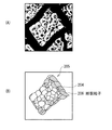
図1は、本発明の一実施の形態に係る負極の断面構成を表している。この負極は、例えば電池などの電気化学デバイスに用いられるものであり、対向する一対の面を有する負極集電体1と、それに設けられた負極活物質層2とを有している。この負極活物質層2は、負極集電体1の両面に設けられていてもよいし、片面だけに設けられていてもよい。
FIG. 1 shows a cross-sectional configuration of a negative electrode according to an embodiment of the present invention. This negative electrode is used for, for example, an electrochemical device such as a battery, and includes a negative electrode
負極集電体1は、良好な電気化学的安定性、電気伝導性および機械的強度を有する材料によって構成されているのが好ましい。このような材料としては、例えば、銅、ニッケルあるいはステンレスなどの金属材料が挙げられ、中でも、銅が好ましい。高い電気伝導性が得られるからである。
The negative
特に、負極集電体1を構成する材料は、電極反応物質と金属間化合物を形成しない1種あるいは2種以上の金属元素を含有しているのが好ましい。電極反応物質と金属間化合物を形成すると、電気化学デバイスの動作時(例えば電池の充放電時)において負極活物質層2の膨張・収縮に伴う応力の影響を受けて集電性が低下したり、負極活物質層2が負極集電体1から剥離する可能性があるからである。このような金属元素としては、例えば、銅、ニッケル、チタン、鉄あるいはクロムなどが挙げられる。
In particular, the material constituting the negative electrode
また、負極集電体1を構成する材料は、負極活物質層2と合金化する1種あるいは2種以上の金属元素を含有しているのが好ましい。負極集電体1と負極活物質層2との間の密着性が向上するため、その負極活物質層2が負極集電体1から剥離しにくくなるからである。電極反応物質と金属間化合物を形成せず、しかも負極活物質層2と合金化する金属元素としては、例えば、負極活物質がケイ素を含有する場合には、銅、ニッケルあるいは鉄などが挙げられる。これらの金属元素は、強度および導電性の観点からも好ましい。
The material constituting the negative electrode
なお、負極集電体1は、単層構造を有していてもよいし、多層構造を有していてもよい。多層構造を有する場合には、例えば、負極活物質層2と隣接する層がそれと合金化する金属材料によって構成され、隣接しない層が他の金属材料によって構成されるのが好ましい。
The negative electrode
負極集電体1の表面は、粗面化されているのが好ましい。いわゆるアンカー効果によって負極集電体1と負極活物質層2との間の密着性が向上するからである。この場合には、少なくとも負極活物質層2と対向する負極集電体1の表面が粗面化されていればよい。粗面化の方法としては、例えば、電解処理によって微粒子を形成する方法などが挙げられる。この電解処理とは、電解槽中において電解法によって負極集電体1の表面に微粒子を形成して凹凸を設ける方法である。この電解処理が施された銅箔は、一般に「電解銅箔」と呼ばれている。
The surface of the negative electrode
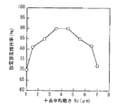
この負極集電体1の表面の十点平均粗さRzは、1.5μm以上6.5μm以下であるのが好ましい。負極集電体1と負極活物質層2との間の密着性がより高くなるからである。詳細には、十点平均粗さRzが1.5μmよりも小さいと、十分な密着性が得られない可能性があり、6.5μmよりも大きいと、負極集電体1の表面凹凸構造に由来する多数の空隙が生じて負極活物質の表面積が増大する可能性がある。
The ten-point average roughness Rz of the surface of the negative electrode
負極活物質層2は、電極反応物質を吸蔵および放出することが可能な負極活物質を含んでおり、その負極活物質は、ケイ素を構成元素として含有している。電極反応物質を吸蔵および放出する能力が高いため、高いエネルギー密度が得られるからである。この負極活物質は、電極反応の前後において複数の細孔を有しており、その細孔の孔径は、およそ数nmから数万nmに渡る広い範囲に分布している。
The negative electrode
ここで、3nm以上200nm以下の微小な孔径を有する細孔(以下、単に「微細孔」という。)に着目すると、電極反応後において、ケイ素の単位重量当たりにおける微細孔群の容積は、0.3cm3 /g以下である。微細孔群の容積が小さくなって負極活物質の表面積が小さく抑えられるため、その負極活物質が電極反応時に高活性になる場合においても他の物質と反応しにくくなるからである。この他の物質としては、例えば、負極が電池に用いられる場合における電解液などが挙げられる。 Here, when attention is paid to pores having minute pore diameters of 3 nm or more and 200 nm or less (hereinafter, simply referred to as “micropores”), the volume of the micropore group per unit weight of silicon after the electrode reaction is 0. 3 cm 3 / g or less. This is because the volume of the micropore group is reduced and the surface area of the negative electrode active material is reduced, so that even when the negative electrode active material becomes highly active during the electrode reaction, it becomes difficult to react with other materials. Examples of the other substance include an electrolytic solution in the case where the negative electrode is used for a battery.
この場合には、ケイ素の単位重量当たりにおける微細孔群の容積が0.1cm3 /g以下であるのが好ましく、0cm3 /gであるのがより好ましい。より高い効果が得られるからである。 In this case, the volume of the micropore group per unit weight of silicon is preferably 0.1 cm 3 / g or less, and more preferably 0 cm 3 / g. This is because a higher effect can be obtained.
上記したケイ素の単位重量当たりにおける微細孔群の容積は、水銀ポロシメータを用いて水銀圧入法によって測定される水銀の浸入量を置き換えたものである。この水銀の浸入量とは、水銀の表面張力および接触角をそれぞれ485mN/mおよび130°とし、細孔の孔径と圧力との間の関係を180/圧力=孔径と近似したときに測定される値である。上記した水銀圧入法によれば、複数の細孔の孔径が広範囲に分布している場合に、その細孔の容積(細孔への水銀の浸入量)を特定の孔径範囲ごとに測定可能であるため、ケイ素の総重量(g)と、3nm以上200nm以下の孔径について測定される水銀の浸入量の総和(微細孔群の総容積:cm3 )とから、ケイ素の単位重量当たりにおける微細孔群の容積(cm3 /g)を算出可能である。なお、ケイ素の単位重量当たりにおける微細孔群の容積の範囲を規定するに当たり、3nm以上200nm以下の孔径の細孔に着目しているのは、容積は小さいが数が極めて多いため、負極活物質の表面積に大きな影響を及ぼすからである。 The volume of the micropore group per unit weight of silicon described above is obtained by replacing the intrusion amount of mercury measured by a mercury intrusion method using a mercury porosimeter. The amount of mercury intrusion is measured when the surface tension and contact angle of mercury are 485 mN / m and 130 °, respectively, and the relationship between pore diameter and pressure is approximated to 180 / pressure = pore diameter. Value. According to the mercury intrusion method described above, when the pore diameters of a plurality of pores are distributed over a wide range, the volume of the pores (the amount of mercury entering the pores) can be measured for each specific pore diameter range. Therefore, from the total weight (g) of silicon and the total amount of mercury intrusion (total volume of the micropore group: cm 3 ) measured for pore diameters of 3 nm or more and 200 nm or less, the fine pores per unit weight of silicon The group volume (cm 3 / g) can be calculated. In defining the volume range of the micropore group per unit weight of silicon, attention is paid to pores having a pore diameter of 3 nm or more and 200 nm or less because the volume is small but the number is extremely large. This is because it greatly affects the surface area.
また、200nm以上の大きな孔径を有する細孔に着目すると、電極反応後において、水銀圧入法によって測定される複数の細孔への水銀の浸入量の変化率は、200nm以上15000nm以下の孔径にピークを示すように分布する。大孔径の細孔の容積が微小孔径の細孔の容積に対して相対的に大きくなるため、負極活物質の表面積が小さくなるからである。また、電極反応後において後述する2次粒子を分離する溝の幅が適正に大きくなるため、その2次粒子の面積が適正に大きくなるからである。これにより、負極活物質が電極反応時に高活性で膨張・収縮する場合においても、他の物質と反応しにくくなると共に、負極活物質層2が負極集電体1から剥離しにくくなる。なお、水銀の浸入量の変化率がピークを示す孔径を規定するに当たり、200nm以上の孔径に着目しているのは、その容積が負極活物質の表面積に大きく寄与せず、しかも膨張・収縮時における負極活物質の逃げ場(空間マージン)として適切な大きさだからである。
Further, when focusing on pores having a large pore diameter of 200 nm or more, the rate of change in the amount of mercury intrusion into the plurality of pores measured by the mercury intrusion method after the electrode reaction peaks at a pore diameter of 200 nm to 15000 nm. Distributed as shown. This is because the surface area of the negative electrode active material is reduced because the volume of the large pore diameter is relatively larger than the volume of the fine pore diameter pore. In addition, since the width of a groove for separating secondary particles described later after the electrode reaction is appropriately increased, the area of the secondary particles is appropriately increased. As a result, even when the negative electrode active material expands and contracts with high activity during the electrode reaction, it is difficult to react with other materials and the negative electrode
この場合には、水銀の浸入量の変化率がピークを示す孔径が700nm以上12000nm以下であるのが好ましく、1000nm以上10000nm以下であるのがより好ましい。より高い効果が得られるからである。 In this case, the hole diameter at which the rate of change of the mercury intrusion amount reaches a peak is preferably 700 nm or more and 12000 nm or less, and more preferably 1000 nm or more and 10,000 nm or less. This is because a higher effect can be obtained.
上記した水銀の浸入量の変化率は、水銀ポロシメータを用いて測定可能であり、その水銀ポロシメータの測定結果から、水銀の浸入量の変化率が200nm以上15000nm以下の孔径にピークを示すか否かを特定可能である。なお、水銀ポロシメータの測定条件は、ケイ素の単位重量当たりにおける微細孔群の容積について説明した場合と同様である。 The above-mentioned change rate of mercury intrusion can be measured using a mercury porosimeter, and from the measurement result of the mercury porosimeter, whether or not the change rate of mercury intrusion shows a peak in the pore diameter of 200 nm to 15000 nm. Can be specified. Note that the measurement conditions of the mercury porosimeter are the same as those described for the volume of the micropore group per unit weight of silicon.
なお、水銀の浸入量の変化率が200nm以上15000nm以下の孔径にピークを示す場合には、200nm未満あるいは15000nm超の孔径に他のピークを示してもよいし、示さなくてもよい。また、200nm以上15000nm以下の孔径におけるピークの数は、1つでもよいし、複数(2つ以上)でもよい。200nm未満あるいは15000nm超の孔径におけるピークの数についても、同様である。 In addition, when the change rate of the mercury intrusion amount shows a peak in the pore diameter of 200 nm or more and 15000 nm or less, another peak may be shown in the pore diameter of less than 200 nm or more than 15000 nm, or may not be shown. Further, the number of peaks in a pore diameter of 200 nm or more and 15000 nm or less may be one or plural (two or more). The same applies to the number of peaks at pore diameters of less than 200 nm or more than 15000 nm.
この負極活物質層2は、必要に応じて、ケイ素の単位重量当たりにおける微細孔群の容積が上記した範囲内になるようにするために、細孔内に埋め込み材を有していてもよい。この埋め込み材としては、例えば、酸化物含有膜、電極反応物質と合金化しない金属材料、あるいはフッ素樹脂などが挙げられる。これらの酸化物含有膜等を細孔内に入り込ませることにより、ケイ素の単位重量当たりにおける微細孔群の容積を所望の値となるように制御可能であるからである。
The negative electrode
酸化物含有膜は、例えば、ケイ素、ゲルマニウムおよびスズからなる群のうちの少なくとも1種の酸化物を含有している。もちろん、これら以外の他の元素の酸化物を含有していてもよい。この酸化物含有膜は、気相法あるいは液相法などのいずれの方法によって形成されていてもよい。中でも、液相析出法、ゾルゲル法、塗布法あるいは浸積法(ディップコーティング法)などの液相法が好ましく、液相析出法がより好ましい。細孔内に酸化物含有膜が入り込みやすいからである。 The oxide-containing film contains, for example, at least one oxide selected from the group consisting of silicon, germanium, and tin. Of course, you may contain the oxide of elements other than these. This oxide-containing film may be formed by any method such as a gas phase method or a liquid phase method. Among these, a liquid phase method such as a liquid phase precipitation method, a sol-gel method, a coating method or an immersion method (dip coating method) is preferable, and a liquid phase precipitation method is more preferable. This is because the oxide-containing film easily enters the pores.
電極反応物質と合金化しない金属材料は、例えば、鉄、コバルト、ニッケル、亜鉛および銅からなる群のうちの少なくとも1種を含有している。もちろん、これら以外の他の金属元素を含有していてもよい。また、単体に限らず、合金や金属化合物であってもよい。この金属材料は、気相法あるいは液相法などのいずれの方法によって形成されていてもよい。中でも、鍍金法(電解鍍金法あるいは無電解鍍金法)などの液相法が好ましく、電解鍍金法がより好ましい。細孔内に金属材料が入り込みやすいと共に、その金属材料の形成に要する時間が短くて済むからである。特に、負極活物質層2が細孔内に上記した金属材料を有していると、その金属材料が結着剤としても機能するため、負極活物質間の結着性が向上する。
The metal material that does not alloy with the electrode reactant contains, for example, at least one member selected from the group consisting of iron, cobalt, nickel, zinc, and copper. Of course, you may contain other metal elements other than these. Moreover, not only a simple substance but an alloy and a metal compound may be sufficient. This metal material may be formed by any method such as a gas phase method or a liquid phase method. Among them, a liquid phase method such as a plating method (electrolytic plating method or electroless plating method) is preferable, and an electrolytic plating method is more preferable. This is because the metal material can easily enter the pores and the time required for forming the metal material can be shortened. In particular, when the negative electrode
フッ素樹脂は、例えば、エーテル結合を有している。エーテル結合を有するフッ素樹脂は、化学的安定性に優れた膜を形成可能だからである。この「エーテル結合を有するフッ素樹脂」とは、直線状の炭素鎖からなる主鎖を含む構造(側鎖はあってもなくてもよい)を有し、その構造中にエーテル結合を有すると共に置換基としてフッ素基を有する高分子化合物の総称である。この場合には、エーテル結合が主鎖あるいは側鎖のいずれにあってもよく、主鎖および側鎖の双方にあってもよい。フッ素基も同様である。もちろん、主鎖中にエーテル結合およびフッ素基の双方を有している場合には、側鎖がなくてもよい。 The fluororesin has, for example, an ether bond. This is because a fluororesin having an ether bond can form a film having excellent chemical stability. This “fluorine resin having an ether bond” has a structure including a main chain composed of linear carbon chains (with or without side chains), and has an ether bond in the structure and is substituted. A generic term for polymer compounds having a fluorine group as a group. In this case, the ether bond may be in either the main chain or the side chain, and may be in both the main chain and the side chain. The same applies to the fluorine group. Of course, when the main chain has both an ether bond and a fluorine group, there may be no side chain.
このフッ素樹脂としては、例えば、化1〜化6で表される高分子化合物からなる群のうちの少なくとも1種が挙げられる。優れた化学的安定性を有する膜を形成可能だからである。化1〜化4に示した高分子化合物は、いわゆるパーフルオロポリエーテルであり、主鎖中にエーテル結合を有していると共に、主鎖中、あるいは主鎖中および側鎖中にフッ素基を有している。この「パーフルオロポリエーテル」とは、エーテル結合と2価のフッ化炭素基(例えば−CF2 −あるいは>CF−CF3 など)とが連結された構造を有する樹脂の総称であり、エーテル結合およびフッ化炭素基の数や結合順などは任意に設定可能である。化5に示した高分子化合物は、主鎖中にエーテル結合を有していると共に、側鎖中にフッ素基を有している。化6に示した高分子化合物は、側鎖中にエーテル結合を有していると共に、主鎖中および側鎖中にフッ素基を有している。なお、化1〜化6に示した化合物の末端は、任意に設定可能であるが、1価のフッ化炭素基(例えば−CF3 など)であるのが好ましい。中でも、フッ素樹脂としては、パーフルオロポリエーテルが好ましい。より化学的安定性に優れた膜を形成しやすいからである。もちろん、フッ素樹脂は、エーテル結合およびフッ素基を有していれば、化1〜化6に示した構造以外の他の構造を有する高分子化合物であってもよい。このフッ素樹脂の構造(高分子化合物の種類)は、例えば、X線光電子分光法(X-ray Photoelectron Spectroscopy:XPS)を用いて元素の結合状態を調べることによって特定可能である。
Examples of the fluororesin include at least one selected from the group consisting of polymer compounds represented by

このフッ素樹脂は、液相法などのいずれの方法によって形成されていてもよい。中でも、スプレー法あるいは浸積法などの液相法が好ましく、浸積法がより好ましい。細孔内にフッ素樹脂が入り込みやすいからである。 This fluororesin may be formed by any method such as a liquid phase method. Among them, a liquid phase method such as a spray method or an immersion method is preferable, and an immersion method is more preferable. This is because the fluororesin tends to enter the pores.
なお、負極活物質層2は、上記した酸化物含有膜等のうちのいずれか1つだけを有していてもよいし、それらを2つ以上組み合わせて有していてもよい。ただし、いずれか1つだけを有する場合には、酸化物含有膜が好ましい。液相析出法などの液相法によって形成された酸化物含有膜は、電解鍍金法などの液相法によって形成された金属材料や、浸積法などの液相法によって形成されたフッ素樹脂よりも、細孔内に入り込みやすいからである。
Note that the negative electrode
負極活物質は、ケイ素の単体、合金あるいは化合物のいずれであってもよいし、それらの1種あるいは2種以上の相を少なくとも一部に有するものであってもよい。これらは単独で用いられてもよいし、複数種が混合されて用いられてもよい。 The negative electrode active material may be any of a simple substance, an alloy, or a compound of silicon, or may have at least a part of one or two or more phases thereof. These may be used alone or in combination of two or more.
なお、本発明における合金には、2種以上の金属元素からなるものに加えて、1種以上の金属元素と1種以上の半金属元素とを含むものも含まれる。もちろん、本発明における合金は、非金属元素を含んでいてもよい。その組織には、固溶体、共晶(共融混合物)、金属間化合物、あるいはそれらの2種以上が共存するものもある。 In addition, the alloy in the present invention includes an alloy containing one or more metal elements and one or more metalloid elements in addition to an alloy composed of two or more metal elements. Of course, the alloy in the present invention may contain a nonmetallic element. Some of the structures include a solid solution, a eutectic (eutectic mixture), an intermetallic compound, or two or more of them.
ケイ素の合金としては、例えば、ケイ素以外の構成元素として、スズ、ニッケル、銅、鉄、コバルト、マンガン(Mn)、亜鉛、インジウム(In)、銀(Ag)、チタン、ゲルマニウム、ビスマス(Bi)、アンチモン(Sb)およびクロムからなる群のうちの少なくとも1種を有するものなどが挙げられる。 Examples of silicon alloys include, as constituent elements other than silicon, tin, nickel, copper, iron, cobalt, manganese (Mn), zinc, indium (In), silver (Ag), titanium, germanium, and bismuth (Bi). And those having at least one selected from the group consisting of antimony (Sb) and chromium.
ケイ素の化合物としては、例えば、ケイ素以外の構成元素として、酸素および炭素(C)を有するものなどが挙げられる。なお、ケイ素の化合物は、例えば、ケイ素以外の構成元素として、ケイ素の合金について説明した一連の元素の1種あるいは2種以上を含んでいてもよい。 Examples of the silicon compound include those having oxygen and carbon (C) as constituent elements other than silicon. The silicon compound may contain, for example, one or more of a series of elements described for the silicon alloy as a constituent element other than silicon.
この負極活物質は、例えば、負極集電体1に連結され、その負極集電体1の表面から負極活物質層2の厚さ方向に成長している。この場合には、負極活物質が気相法によって形成されており、上記したように、負極集電体1と負極活物質層2との界面の少なくとも一部において合金化しているのが好ましい。具体的には、両者の界面において、負極集電体1の構成元素が負極活物質に拡散していてもよいし、負極活物質の構成元素が負極集電体1に拡散していてもよいし、両者の構成元素が互いに拡散しあっていてもよい。電極反応時に負極活物質層2が膨張・収縮しても破損しにくくなると共に、負極集電体1と負極活物質層2との間において電子伝導性が向上するからである。
For example, the negative electrode active material is connected to the negative electrode
上記した気相法としては、例えば、物理堆積法あるいは化学堆積法、より具体的には真空蒸着法、スパッタ法、イオンプレーティング法、レーザーアブレーション法、熱化学気相成長(chemical vapor deposition :CVD)法あるいはプラズマ化学気相成長法などが挙げられる。 Examples of the vapor phase method include physical deposition method or chemical deposition method, more specifically, vacuum evaporation method, sputtering method, ion plating method, laser ablation method, thermal chemical vapor deposition (CVD). ) Method or plasma enhanced chemical vapor deposition.
また、負極活物質は、複数の粒子状をなしていてもよい。この負極活物質は、1回の堆積工程で形成されて単層構造を有していてもよいし、複数回の堆積工程で形成されて粒子内に多層構造を有していてもよい。ただし、堆積時に高熱を伴う蒸着法などによって負極活物質を形成する場合に、負極集電体1が熱的ダメージを受けることを抑制するためには、負極活物質が多層構造を有しているのが好ましい。負極活物質の堆積工程を複数回に分割して行う(負極活物質を順次形成して堆積させる)ことにより、その堆積工程を1回で行う場合と比較して、負極集電体1が高熱に晒される時間が短くなるからである。
Further, the negative electrode active material may be in the form of a plurality of particles. The negative electrode active material may be formed by a single deposition process and have a single layer structure, or may be formed by a plurality of deposition processes and have a multilayer structure in the particles. However, in order to suppress the negative electrode
特に、負極活物質は、酸素を構成元素として含有しているのが好ましい。負極活物質層2の膨張および収縮が抑制されるからである。この負極活物質層2では、少なくとも一部の酸素が一部のケイ素と結合しているのが好ましい。この場合には、結合の状態が一酸化ケイ素や二酸化ケイ素であってもよいし、他の準安定状態であってもよい。
In particular, the negative electrode active material preferably contains oxygen as a constituent element. This is because expansion and contraction of the negative electrode
負極活物質中における酸素の含有量は、3原子数%以上40原子数%以下であるのが好ましい。より高い効果が得られるからである。詳細には、酸素の含有量が3原子数%よりも少ないと、負極活物質層2の膨張・収縮が十分に抑制されない可能性があり、40原子数%よりも多いと、抵抗が増大しすぎる可能性がある。なお、電気化学デバイスにおいて負極が電解液と共に用いられる場合には、その電解液の分解によって形成される被膜などは負極活物質に含めないこととする。すなわち、負極活物質中における酸素の含有量を算出する場合には、上記した被膜中の酸素は含めない。
The oxygen content in the negative electrode active material is preferably 3 atomic% to 40 atomic%. This is because a higher effect can be obtained. Specifically, if the oxygen content is less than 3 atomic%, the negative electrode
酸素を含有する負極活物質は、例えば、気相法によって負極活物質を形成する際に、チャンバ内に連続的に酸素ガスを導入することによって形成可能である。特に、酸素ガスを導入しただけでは所望の酸素含有量が得られない場合には、チャンバ内に酸素の供給源として液体(例えば水蒸気など)を導入してもよい。 The negative electrode active material containing oxygen can be formed by, for example, continuously introducing oxygen gas into the chamber when forming the negative electrode active material by a vapor phase method. In particular, when a desired oxygen content cannot be obtained simply by introducing oxygen gas, a liquid (for example, water vapor) may be introduced into the chamber as an oxygen supply source.
また、負極活物質は、鉄、コバルト、ニッケル、チタン、クロムおよびモリブデンからなる群のうちの少なくとも1種の金属元素を構成元素として含有しているのが好ましい。負極活物質の結着性が向上し、負極活物質層2の膨張・収縮が抑制され、負極活物質の抵抗が低下するからである。負極活物質中における金属元素の含有量は、任意に設定可能である。ただし、負極が電池に用いられる場合には、金属元素の含有量が多くなりすぎると、所望の電池容量を得るために負極活物質層2を厚くしなければならず、負極活物質層2が負極集電体1から剥がれたり、割れる可能性がある。
The negative electrode active material preferably contains at least one metal element selected from the group consisting of iron, cobalt, nickel, titanium, chromium and molybdenum as a constituent element. This is because the binding property of the negative electrode active material is improved, the expansion / contraction of the negative electrode
上記した金属元素を含有する負極活物質は、例えば、気相法として蒸着法によって負極活物質を形成する際に、金属元素を混合させた蒸着源を用いたり、多元系の蒸着源を用いることによって形成可能である。 For the negative electrode active material containing the metal element described above, for example, when forming the negative electrode active material by vapor deposition as a vapor phase method, a vapor deposition source in which metal elements are mixed or a multi-component vapor deposition source is used. Can be formed.
この負極活物質は、その厚さ方向において、酸素を有する酸素含有領域を有し、その酸素含有領域における酸素の含有量は、それ以外の領域における酸素の含有量よりも高くなっているのが好ましい。負極活物質層2の膨張・収縮が抑制されるからである。この酸素含有領域以外の領域は、酸素を有していてもよいし、有していなくてもよい。もちろん、酸素含有領域以外の領域も酸素を有している場合に、その酸素の含有量が酸素含有領域における酸素の含有量よりも低くなっていることは言うまでもない。
This negative electrode active material has an oxygen-containing region having oxygen in the thickness direction, and the oxygen content in the oxygen-containing region is higher than the oxygen content in other regions. preferable. This is because expansion / contraction of the negative electrode
この場合には、負極活物質層2の膨張・収縮をより抑制するために、酸素含有領域以外の領域も酸素を有しており、負極活物質が、第1の酸素含有領域(より低い酸素含有量を有する領域)と、それよりも高い酸素含有量を有する第2の酸素含有領域(より高い酸素含有量を有する領域)とを有しているのが好ましい。この場合には、第1の酸素含有領域によって第2の酸素含有領域が挟まれているのが好ましく、第1および第2の酸素含有領域が交互に繰り返して積層されているのがより好ましい。より高い効果が得られるからである。第1の酸素含有領域における酸素の含有量は、できるだけ少ないのが好ましく、第2の酸素含有領域における酸素の含有量は、例えば、上記した負極活物質が酸素を含有する場合の含有量と同様である。
In this case, in order to further suppress the expansion / contraction of the negative electrode
第1および第2の酸素含有領域を有する負極活物質は、例えば、気相法によって負極活物質を形成する際に、チャンバ内に断続的に酸素ガスを導入したり、チャンバ内に導入する酸素ガスの量を変化させることによって形成可能である。もちろん、酸素ガスを導入しただけでは所望の酸素含有量が得られない場合には、チャンバ内に液体(例えば水蒸気など)を導入してもよい。 The negative electrode active material having the first and second oxygen-containing regions is, for example, an oxygen gas that is intermittently introduced into the chamber or oxygen introduced into the chamber when the negative electrode active material is formed by a vapor phase method. It can be formed by changing the amount of gas. Of course, when a desired oxygen content cannot be obtained simply by introducing oxygen gas, a liquid (for example, water vapor) may be introduced into the chamber.
なお、第1および第2の酸素含有領域の間では、酸素の含有量が明確に異なっていてもよいし、明確に異なっていなくてもよい。特に、上記した酸素ガスの導入量を連続的に変化させた場合には、酸素の含有量も連続的に変化していてもよい。第1および第2の酸素含有領域は、酸素ガスの導入量を断続的に変化させた場合には、いわゆる「層」となり、一方、酸素ガスの導入量を連続的に変化させた場合には、「層」というよりもむしろ「層状」となる。後者の場合には、負極活物質中において酸素の含有量が高低を繰り返しながら分布する。この場合には、第1および第2の酸素含有領域の間において、酸素の含有量が段階的あるいは連続的に変化しているのが好ましい。酸素の含有量が急激に変化すると、イオンの拡散性が低下したり、抵抗が増大する可能性があるからである。 Note that the oxygen content may be clearly different between the first and second oxygen-containing regions, or may not be clearly different. In particular, when the amount of oxygen gas introduced is continuously changed, the oxygen content may also be continuously changed. The first and second oxygen-containing regions become so-called “layers” when the amount of oxygen gas introduced is changed intermittently, while when the amount of oxygen gas introduced is changed continuously. , Rather than “layer”. In the latter case, the oxygen content in the negative electrode active material is distributed while repeating high and low. In this case, it is preferable that the oxygen content changes stepwise or continuously between the first and second oxygen-containing regions. This is because if the oxygen content changes rapidly, the diffusibility of ions may decrease or the resistance may increase.
ここで、粒子状の負極活物質がその粒子内に多層構造を有する場合を例に挙げることにより、図2〜図7を参照して、負極の詳細な構成を電極反応の前後に分けて説明する。以下で説明する「電極反応後」とは、少なくとも1回の電極反応を経た状態を意味する。 Here, by taking as an example a case where the particulate negative electrode active material has a multilayer structure in the particle, the detailed configuration of the negative electrode will be described separately before and after the electrode reaction with reference to FIGS. To do. “After electrode reaction” described below means a state in which at least one electrode reaction has been performed.
図2は電極反応前における負極の断面構造を拡大して表しており、(A)は走査型電子顕微鏡(scanning electron microscope:SEM)写真(二次電子像)、(B)は(A)に示したSEM像の模式絵である。なお、図2では、負極活物質が多層構造を有していると共に負極活物質層2が酸化物含有膜等の埋め込み材を有していない場合を示している。
FIG. 2 shows an enlarged cross-sectional structure of the negative electrode before the electrode reaction, (A) is a scanning electron microscope (SEM) photograph (secondary electron image), and (B) is (A). It is a schematic picture of the shown SEM image. FIG. 2 shows a case where the negative electrode active material has a multilayer structure and the negative electrode
電極反応前には、図2に示したように、負極活物質が複数の粒子状(負極活物質粒子201)をなしていることに伴い、その負極活物質が複数の細孔202を有している。詳細には、粗面化された負極集電体1の表面には、複数の突起部(例えば電解処理によって形成された微粒子)が存在している。この場合には、気相法などによって負極集電体1の表面に複数回に渡って負極活物質が堆積されると、上記した突起部ごとに負極活物質粒子201が厚さ方向に段階的に成長する。この複数の負極活物質粒子201の密集構造、多層構造および表面構造に伴い、複数の細孔202が生じている。
Before the electrode reaction, as shown in FIG. 2, the negative electrode active material has a plurality of fine particles 202 (negative electrode active material particles 201), and the negative electrode active material has a plurality of
この細孔202は、例えば、発生原因に応じて分類された3種類の細孔202A〜202Cを含んでいる。細孔202Aは、負極集電体1の表面に存在する突起部ごとに負極活物質粒子201が成長することに伴い、各負極活物質粒子201間に生じる隙間である。細孔202Bは、負極活物質粒子201の表面にひげ状の微細な突起部(図示せず)が生じることに伴い、その突起部間に生じる空隙である。この細孔202Bは、負極活物質粒子201の露出面の全体に渡って生じる場合もあれば、一部だけに生じる場合もある。細孔202Cは、負極活物質粒子201が多層構造を有することに伴い、各階層間に生じる隙間である。なお、上記したひげ状の微細な突起部は、負極活物質粒子201の形成時ごとに表面に生じるため、細孔202Bは、負極活物質粒子201の露出面(最表面)だけでなく、各階層間にも生じている。もちろん、細孔202は、上記した発生原因以外の発生原因によって生じた他の細孔も含んでいてもよい。
The
図3は電極反応前における負極の他の断面構造を表しており、図2に対応している。なお、図3では、負極活物質層2が埋め込み材として電極反応物質と合金化しない金属材料を有している場合を示している。図3に示したように、複数の負極活物質粒子201が形成されたのち、液相法などによって金属材料203が形成されると、その金属材料203は細孔202内に入り込む。すなわち、金属材料203は、隣接する負極活物質粒子201間の隙間(細孔202A)や、負極活物質粒子201の表面に生じたひげ状の微細な突起部間の空隙(細孔202B)や、負極活物質粒子201内の隙間(細孔202C)に入り込む。図3において、最上層の負極活物質粒子201の表面に金属材料203が点在していることは、その点在箇所に上記した微細な突起部が存在していること表している。
FIG. 3 shows another cross-sectional structure of the negative electrode before the electrode reaction, and corresponds to FIG. FIG. 3 shows a case where the negative electrode
図2および図3に示したように、粒子状の負極活物質がその粒子内に多層構造を有している場合には、複数の細孔202は細孔202A〜202Cを含んでいる。これに対して、粒子状の負極活物質がその粒子内に多層構造を有していない(単層構造を有している)場合には、細孔202Cが生じないことから、複数の細孔202は細孔202A,202Bを含むこととなる。
As shown in FIGS. 2 and 3, when the particulate negative electrode active material has a multilayer structure in the particle, the plurality of
ここでは具体的に図面を参照して説明しないが、金属材料に代えて、液相析出法などによって酸化物含有膜を形成した場合には、その酸化物含有膜が負極活物質粒子201の表面に沿って成長するため、細孔202B,202Cに優先的に入り込みやすい。この場合には、析出時間を長くすれば、酸化物含有膜が細孔202Aまで入り込む。また、浸積法などによってフッ素樹脂を形成した場合には、金属材料と同様に細孔202A〜202Cに入り込みやすく、浸積時間を長くすれば、細孔202B,202Cにより入り込みやすい。
Here, although not specifically described with reference to the drawings, when an oxide-containing film is formed by a liquid deposition method or the like instead of the metal material, the oxide-containing film is formed on the surface of the negative electrode
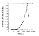
図7は電極反応の前後における水銀の浸入量の変化率の分布を表す図であり、横軸は細孔202の孔径(nm)、縦軸は複数の細孔202への水銀の浸入量の変化率を示している。電極反応前において、水銀ポロシメータを用いて圧力Pを段階的に増加させながら複数の細孔202への水銀の浸入量Vを測定すると、その水銀の浸入量の変化率(ΔV/ΔP)は、図7に示した7A(破線)のように分布する。この水銀の浸入量の変化率は、水銀ポロシメータを用いて測定可能な約3nm以上100000nm以下の孔径において、2つのピークP1,P2を示すように分布する。大孔径側のピークP1は、主に細孔202Aの存在に起因して生じたものであり、そのピークP1が現れる孔径の範囲は、およそ50nm以上3000nm以下である。一方、小孔径側のピークP2は、主に細孔202B,202Cの存在に起因して生じたものであり、そのピークP2が現れる孔径の範囲は、およそ3nm以上50nm以下である。なお、図7に示した水銀の浸入量の変化率(7A)は、ピークP1における変化率を1として規格化した値である。
FIG. 7 is a graph showing the distribution of the change rate of mercury intrusion before and after the electrode reaction. The horizontal axis represents the pore diameter (nm) of the
図4〜図6は、電極反応後における負極活物質層2の粒子構造を表している。このうち、図4および図5はそれぞれ表面および断面の粒子構造を示しており、(A)はSEM写真、(B)は(A)に示したSEM像の模式絵である。また、図6は図4に示した粒子構造の一部を拡大して示しており、(A)は走査型イオン顕微鏡(scanning ion microscope :SIM)写真、(B)は(A)に示したSIM像の模式絵である。なお、図4〜図6では、負極活物質が単層構造を有している場合を示している。
4 to 6 show the particle structure of the negative electrode
負極活物質層2では、図4〜図6に示したように、電極反応後において複数の1次粒子204によって2次粒子205が形成されると共に、断裂粒子206が形成される。詳細には、図4(A)に示したSEM写真のうち、(B)においてハッチングを付している部分に対応する部分が2次粒子205であり、その2次粒子205中に粒状に見えているのが1次粒子204である。また、図5(A)に示したSEM写真のうち、(B)においてハッチングを付している部分に対応する部分が1次粒子204(単層構造を有する負極活物質)である。2次粒子205は、負極活物質層2の厚さ方向に深さを有する溝203によって負極活物質層2の面内方向において分離されている。この際、図5および図6に示したように、各1次粒子204は単に隣接しているのではなく、互いに少なくとも一部が接合して2次粒子205を形成しており、溝203はほぼ負極集電体1まで達している。溝203の深さは、例えば、5μm以上である。この溝203は、電極反応(負極が電池に用いられた場合には充放電反応)によって形成されたものであり、1次粒子204に沿って割れているのではなく、負極活物質層2の厚さ方向においてほぼ直線状に生じている。これにより、図4および図6に示したように、1次粒子204の一部は、溝203によって断裂された断裂粒子206となっている。図6(A)に示したSIM写真のうち、(B)において網掛けを付している部分に対応する部分が断裂粒子206である。
In the negative electrode
これらの粒子構造については、例えば、図4(A)および図5(A)に示したようにSEMで観察してもよいし、図6(A)に示したようにSIMで観察してもよい。また、観察する断面については、集束イオンビーム(focused ion beam:FIB)あるいはミクロトームなどで切り出すのが好ましい。 For example, these particle structures may be observed with an SEM as shown in FIGS. 4A and 5A, or with a SIM as shown in FIG. 6A. Good. The cross section to be observed is preferably cut out with a focused ion beam (FIB) or a microtome.
電極反応後において、電極反応前と同様に水銀ポロシメータを用いて水銀の浸入量の変化率を測定すると、その水銀の浸入量の変化率は、図7に示した7B(実線)のように分布する。この水銀の浸入量の変化率は、水銀ポロシメータを用いて測定可能な約3nm以上100000nm以下の孔径において、1つのピークP3を示すように分布する。このピークP3は、主に溝203の存在に起因して生じたものであり、そのピークP3が現れる孔径の範囲は、上記したように、200nm以上15000nm以下である。なお、図7に示した水銀の浸入量の変化率(7B)は、ピークP3における変化率を1として規格化した値である。
After the electrode reaction, when the rate of change of mercury intrusion is measured using a mercury porosimeter in the same manner as before the electrode reaction, the rate of change of mercury intrusion is distributed as shown by 7B (solid line) in FIG. To do. The change rate of the mercury intrusion amount is distributed so as to show one peak P3 in a pore diameter of about 3 nm or more and 100,000 nm or less that can be measured using a mercury porosimeter. This peak P3 is mainly caused by the presence of the
図7に示したように、電極反応の前後において水銀の浸入量の変化率の分布が変化するのは、電極反応を経て負極活物質層2の内部構造が変化するからである。詳細には、充放電時には、負極活物質層2の膨張・収縮に伴う応力の影響を受けて負極活物質層2の粒子構造が力学的に変化すると共に、負極が電解液と共に電気化学デバイス用いられた場合にはいわゆるSEI(Solid Electrolyte Interface )膜が形成され、細孔202A〜202Cが塞がりやすくなる。この傾向は、上記した酸化物含有膜等の埋め込み材を形成すれば、より顕著になる。また、充放電時には、複数の1次粒子204が集合して2次粒子205(断裂粒子206を含む)になるため、それに応じて細孔202Aよりも大きな孔径を有する溝203が新たに形成される。なお、上記した「SEI膜」とは、非水溶媒系の電解液中において初回の充電時に負極活物質と電解液との間で不可逆的な反応が生じることにより、負極と電解液との間に形成される膜である。このSEI膜は、負極と電解液との間に電極反応物質イオンの伝導性はあるが電子の伝導性はない安定界面を形成し、電解液の分解生成物などを含む。
As shown in FIG. 7, the distribution of the change rate of the mercury intrusion amount before and after the electrode reaction changes because the internal structure of the negative electrode
この負極は、例えば、以下の手順によって製造可能である。 This negative electrode can be manufactured, for example, by the following procedure.
最初に、負極集電体1を準備したのち、必要に応じて、負極集電体1の表面に粗面化処理を施す。この場合には、あらかじめ粗面化された負極集電体1を用いてもよい。
First, after preparing the negative electrode
続いて、気相法などによって負極集電体1上に負極活物質としてケイ素を堆積させて負極活物質層2を形成する。この負極活物質を堆積させる場合には、1回の堆積工程によって単層構造となるようにしてもよいし、複数回の堆積工程によって多層構造となるようにしてもよい。気相法によって負極活物質を多層構造となるように形成する場合には、蒸着源に対して負極集電体1を相対的に往復移動させながらケイ素を順次堆積させるようにしてもよいし、蒸着源に対して負極集電体1を固定させたままでシャッターの開閉を繰り返しながらケイ素を順次堆積させるようにしてもよい。この負極活物質層2を形成する場合には、必要に応じて、液相法などによって酸化物含有膜、電極反応物質と合金化しない金属材料、あるいはフッ素樹脂などの埋め込み材を形成してもよい。
Subsequently, silicon is deposited as a negative electrode active material on the negative electrode
最後に、少なくとも1回の電極反応を進行させて、負極活物質層2中に溝203によって分離された複数の2次粒子205(断裂粒子206を含む)を形成する。この場合には、電極反応後において、ケイ素の単位重量当たりにおける微細孔群の容積が0.3cm3 /g以下になり、水銀圧入法によって測定される複数の細孔への水銀の浸入量の変化率が200nm以上15000nm以下の孔径にピークを示すようにする。これにより、負極が完成する。
Finally, at least one electrode reaction is performed to form a plurality of secondary particles 205 (including fractured particles 206) separated by the
この負極を製造する場合には、例えば、以下の方法により、ケイ素の単位重量当たりにおける微細孔群の容積や、水銀の浸入量の変化率がピークを示す孔径を調整可能である。 When manufacturing this negative electrode, for example, the following method can be used to adjust the volume of the micropore group per unit weight of silicon and the hole diameter at which the rate of change in the amount of mercury intrusion shows a peak.
ケイ素の単位重量当たりにおける微細孔群の容積を調整するためには、酸化物含有膜などの埋め込み材を形成する場合に、その形成時間を変化させる。この形成時間とは、液相析出法によって酸化物含有膜を形成する場合には析出時間であり、鍍金法によって金属材料を形成する場合には鍍金時間であり、浸積法によってフッ素樹脂を形成する場合には浸積時間である。いずれの場合においても、形成時間に応じてケイ素の単位重量当たりにおける微細孔群の容積を変化させることが可能である。 In order to adjust the volume of the micropore group per unit weight of silicon, when forming a filling material such as an oxide-containing film, the formation time is changed. This formation time is the deposition time when an oxide-containing film is formed by a liquid phase deposition method, and the plating time when a metal material is formed by a plating method, and a fluororesin is formed by an immersion method. If so, it is the immersion time. In any case, the volume of the micropore group per unit weight of silicon can be changed according to the formation time.
一方、水銀の浸入量の変化率がピークを示す孔径を調整するためには、炭酸ガスや不活性ガスなどの各種ガスをチャンバ内に導入し、そのガス導入量を変化させる。また、気相法によって負極活物質を堆積させる場合には、基板温度を変化させる。さらに、気相法によって蒸着源に対して負極集電体1を相対的に移動させながら負極活物質を堆積させる場合に、その負極集電体1の移動速度を変化させる。いずれの場合においても、ガス導入量、基板温度あるいは負極集電体1の移動速度に応じて、水銀の浸入量の変化率がピークを示す孔径を変化させることが可能である。
On the other hand, in order to adjust the hole diameter at which the rate of change in the mercury intrusion amount reaches a peak, various gases such as carbon dioxide and inert gas are introduced into the chamber, and the amount of gas introduced is changed. When the negative electrode active material is deposited by a vapor phase method, the substrate temperature is changed. Further, when the negative electrode active material is deposited while moving the negative electrode
この負極によれば、ケイ素を含有する負極活物質が複数の細孔を有する場合に、電極反応後において、ケイ素の単位重量当たりにおける微細孔群(3nm以上200nm以下の孔径の細孔群)の容積が0.3cm3 /g以下であり、水銀圧入法によって測定される細孔への水銀の浸入量の変化率が200nm以上15000nm以下の孔径にピークを示すように分布する。この場合には、上記したケイ素の単位重量当たりにおける微細孔群の容積および水銀の浸入量の変化率がピークを示す孔径が範囲外である場合と比較して、電極反応時に負極活物質が高活性で膨張・収縮しやすい場合においても、負極活物質が他の物質と反応しにくくなると共に、負極活物質層2が負極集電体1から剥離しにくくなる。したがって、負極を用いた電気化学デバイスのサイクル特性の向上に寄与することができる。
According to this negative electrode, when the negative electrode active material containing silicon has a plurality of pores, a group of fine pores (a pore group having a pore diameter of 3 nm or more and 200 nm or less) per unit weight of silicon after the electrode reaction. The volume is 0.3 cm 3 / g or less, and the change rate of the mercury intrusion amount measured by the mercury intrusion method is distributed so as to show a peak in the pore diameter of 200 nm or more and 15000 nm or less. In this case, the negative electrode active material is higher during the electrode reaction than in the case where the pore diameter at which the change rate of the volume of the micropores per unit weight of silicon and the intrusion amount of mercury show a peak is out of the range. Even when active and easily expand / shrink, the negative electrode active material is less likely to react with other materials, and the negative electrode
特に、ケイ素の単位重量当たりにおける微細孔群の容積および水銀の浸入量の変化率がピークを示す孔径がそれぞれ0.1cm3 /g以下および700nm以上12000nm以下、さらに0cm3 /gおよび1000nm以上10000nm以下であれば、サイクル特性をより向上させることができる。 Particularly, the pore diameters at which the change rate of the volume of micropores per unit weight of silicon and the rate of change of mercury intrusion peak are 0.1 cm 3 / g or less and 700 nm or more and 12000 nm or less, respectively 0 cm 3 / g and 1000 nm or more and 10000 nm. If it is below, the cycle characteristics can be further improved.
また、細孔内に酸化物含有膜、電極反応物質と合金化しない金属材料、あるいはフッ素樹脂などの埋め込み材を有していれば、ケイ素の単位重量当たりにおける微細孔群の容積が本来的に上記した範囲外である場合においても、その範囲内となるように容易に制御することができる。この場合には、酸化物含有膜が液相析出法などの液相法によって形成されており、電極反応物質と合金化しない金属材料が電解鍍金法などの液相法によって形成されており、あるいはフッ素樹脂が浸積法などの液相によって形成されていれば、それらの埋め込み材が細孔内に入り込みやすくなるため、より高い効果を得ることができる。 In addition, if the pores have an oxide-containing film, a metal material that does not alloy with the electrode reactant, or an embedding material such as a fluororesin, the volume of the micropore group per unit weight of silicon is inherently low. Even when it is out of the above range, it can be easily controlled so as to be within the range. In this case, the oxide-containing film is formed by a liquid phase method such as a liquid phase deposition method, and a metal material that does not alloy with the electrode reactant is formed by a liquid phase method such as an electrolytic plating method, or If the fluororesin is formed by a liquid phase such as an immersion method, the embedding material easily enters the pores, so that a higher effect can be obtained.
なお、上記した埋め込み材の形成に時間を要する場合には、負極の製造時間を短縮して生産性を高めることを重視すれば、ケイ素の単位重量当たりにおける微細孔群の容積は上記した範囲内においてできるだけ大きいのが好ましく、具体的には0.3cm3 /g以下であるのが好ましい。 In addition, when it takes time to form the above-described embedding material, the volume of the fine pore group per unit weight of silicon is within the above range if importance is attached to shortening the production time of the negative electrode and increasing the productivity. Is preferably as large as possible, specifically 0.3 cm 3 / g or less.
特に、負極活物質が酸素を含有し、負極活物質中における酸素の含有量が3原子数%以上40原子数%以下であり、あるいは負極活物質が鉄、コバルト、ニッケル、チタン、クロムおよびモリブデンからなる群のうちの少なくとも1種の金属元素を含有し、または負極活物質粒子がその厚さ方向において酸素含有領域(酸素を有し、酸素の含有量がそれ以外の領域よりも高い領域)を含んでいれば、サイクル特性をより向上させることができる。 In particular, the negative electrode active material contains oxygen, and the oxygen content in the negative electrode active material is 3 atomic% to 40 atomic%, or the negative electrode active material is iron, cobalt, nickel, titanium, chromium, and molybdenum. Containing at least one metal element from the group consisting of, or the negative electrode active material particles having an oxygen-containing region in the thickness direction (region having oxygen and having a higher oxygen content than the other regions) If it contains, cycling characteristics can be improved more.
また、負極活物質層2と対向する負極集電体1の表面が電解処理で形成された微粒子によって粗面化されていれば、負極集電体1と負極活物質層2との間の密着性を高めることができる。この場合には、負極集電体1の表面の十点平均粗さRzが1.5μm以上6.5μm以下であれば、サイクル特性をより向上させることができる。
Further, if the surface of the negative electrode
次に、上記した負極の使用例について説明する。ここで、電気化学デバイスの一例として電池を例に挙げると、負極は以下のようにして電池に用いられる。 Next, usage examples of the above-described negative electrode will be described. Here, taking a battery as an example of an electrochemical device, the negative electrode is used in the battery as follows.
(第1の電池)
図8および図9は第1の電池の断面構成を表しており、図9では図8に示したIX−IX線に沿った断面を示している。ここで説明する電池は、例えば、負極22の容量が電極反応物質であるリチウムの吸蔵および放出に基づいて表されるリチウムイオン二次電池である。
(First battery)
8 and 9 show a cross-sectional configuration of the first battery, and FIG. 9 shows a cross-section along the line IX-IX shown in FIG. The battery described here is, for example, a lithium ion secondary battery in which the capacity of the negative electrode 22 is expressed based on insertion and extraction of lithium as an electrode reactant.
この二次電池は、主に、電池缶11の内部に、扁平な巻回構造を有する電池素子20が収納されたものである。
In the secondary battery, a
電池缶11は、例えば、角型の外装部材である。この角型の電池缶11を用いた電池構造は、角型と呼ばれている。角型の外装部材とは、図9に示したように、長手方向の断面が矩形型あるいは略矩形型(一部に曲線を含む)の形状を有するものであり、矩形状だけでなくオーバル形状の角型電池も構成するものである。すなわち、角型の外装部材とは、矩形状あるいは円弧を直線で結んだ略矩形状(長円形状)の開口部を有する有底矩形型あるいは有底長円形状型の器状部材である。なお、図9では、電池缶11が矩形型の断面形状を有する場合を示している。 The battery can 11 is, for example, a square exterior member. A battery structure using the square battery can 11 is called a square battery. As shown in FIG. 9, the rectangular exterior member has a rectangular cross section or a substantially rectangular shape (including a curve in part), and is not only a rectangular shape but also an oval shape. The prismatic battery is also constructed. That is, the square-shaped exterior member is a bottomed rectangular type or bottomed oval shaped vessel-like member having a rectangular shape or a substantially rectangular shape (oval shape) obtained by connecting arcs with straight lines. FIG. 9 shows a case where the battery can 11 has a rectangular cross-sectional shape.
この電池缶11は、例えば、鉄、アルミニウム(Al)あるいはそれらの合金を含有する材料によって構成されており、電極端子としての機能を有していてもよい。この場合には、充放電時に電池缶11の固さ(変形しにくさ)を利用して二次電池の膨れを抑えるために、アルミニウムよりも固い鉄が好ましい。電池缶11が鉄によって構成される場合には、例えば、ニッケルなどの鍍金が施されていてもよい。 The battery can 11 is made of, for example, a material containing iron, aluminum (Al), or an alloy thereof, and may have a function as an electrode terminal. In this case, iron that is harder than aluminum is preferable in order to suppress swelling of the secondary battery by utilizing the hardness (hardness of deformation) of the battery can 11 during charging and discharging. When the battery can 11 is made of iron, for example, a plating such as nickel may be applied.
また、電池缶11は、一端部および他端部がそれぞれ閉鎖および開放された中空構造を有しており、その開放端部に絶縁板12および電池蓋13が取り付けられて密閉されている。絶縁板12は、電池素子20と電池蓋13との間に、その電池素子20の巻回周面に対して垂直に配置されており、例えば、ポリプロピレンなどによって構成されている。電池蓋13は、例えば、電池缶11と同様の材料によって構成されており、それと同様に電極端子としての機能を有していてもよい。
The battery can 11 has a hollow structure in which one end and the other end are closed and opened, respectively, and an insulating plate 12 and a
電池蓋13の外側には、正極端子となる端子板14が設けられており、その端子板14は、絶縁ケース16を介して電池蓋13から電気的に絶縁されている。この絶縁ケース16は、例えば、ポリブチレンテレフタレートなどによって構成されている。また、電池蓋13のほぼ中央には貫通孔が設けられており、その貫通孔には、端子板14と電気的に接続されると共にガスケット17を介して電池蓋13から電気的に絶縁されるように正極ピン15が挿入されている。このガスケット17は、例えば、絶縁材料によって構成されており、その表面にはアスファルトが塗布されている。
A
電池蓋13の周縁付近には、開裂弁18および注入孔19が設けられている。開裂弁18は、電池蓋13と電気的に接続されており、内部短絡あるいは外部からの加熱などに起因して電池の内圧が一定以上になると、電池蓋13から切り離されて内圧を開放するようになっている。注入孔19は、例えば、ステンレス鋼球からなる封止部材19Aによって塞がれている。
In the vicinity of the periphery of the
電池素子20は、正極21と負極22とがセパレータ23を介して積層されてから巻回されたものであり、電池缶11の形状に応じて扁平状になっている。正極21の端部(例えば内終端部)にはアルミニウムなどによって構成された正極リード24が取り付けられており、負極22の端部(例えば外終端部)にはニッケルなどによって構成された負極リード25が取り付けられている。正極リード24は、正極ピン15の一端に溶接されて端子板14と電気的に接続されており、負極リード25は、電池缶11に溶接されて電気的に接続されている。
The
正極21は、例えば、帯状の正極集電体21Aの両面に正極活物質層21Bが設けられたものである。ただし、正極活物質層21Bは、正極集電体21Aの片面だけに設けられていてもよい。正極集電体21Aは、例えば、アルミニウム、ニッケルあるいはステンレスなどの材料によって構成されている。正極活物質層21Bは、正極活物質として、リチウムを吸蔵および放出することが可能な材料のいずれか1種あるいは2種以上を含んでおり、必要に応じて導電剤や結着剤などの他の材料を含んでいてもよい。
The
リチウムを吸蔵および放出することが可能な材料としては、リチウム含有化合物が好ましい。高いエネルギー密度が得られるからである。このリチウム含有化合物としては、例えば、リチウムと遷移金属元素とを含む複合酸化物、あるいはリチウムと遷移金属元素とを含むリン酸化合物が挙げられ、特に、遷移金属元素としてコバルト、ニッケル、マンガンおよび鉄からなる群のうちの少なくとも1種を含むものが好ましい。より高い電圧が得られるからである。その化学式は、例えば、Lix M1O2 あるいはLiy M2PO4 で表される。式中、M1およびM2は、1種類以上の遷移金属元素を表す。また、xおよびyの値は電池の充放電状態によって異なり、通常、0.05≦x≦1.10、0.05≦y≦1.10である。 As a material capable of occluding and releasing lithium, a lithium-containing compound is preferable. This is because a high energy density can be obtained. Examples of the lithium-containing compound include a composite oxide containing lithium and a transition metal element, or a phosphate compound containing lithium and a transition metal element. In particular, cobalt, nickel, manganese, and iron are used as the transition metal element. What contains at least 1 sort (s) of the group which consists of is preferable. This is because a higher voltage can be obtained. The chemical formula is represented by, for example, Li x M1O 2 or Li y M2PO 4 . In the formula, M1 and M2 represent one or more transition metal elements. The values of x and y vary depending on the charge / discharge state of the battery, and are generally 0.05 ≦ x ≦ 1.10 and 0.05 ≦ y ≦ 1.10.
リチウムと遷移金属元素とを含むリチウム複合酸化物としては、例えば、リチウムコバルト複合酸化物(Lix CoO2 )、リチウムニッケル複合酸化物(Lix NiO2 )、リチウムニッケルコバルト複合酸化物(Lix Ni(1-z) Coz O2 (z<1))、リチウムニッケルコバルトマンガン複合酸化物(Lix Ni(1-v-w) Co v Mnw O2 (v+w<1))、あるいはスピネル型構造を有するリチウムマンガン複合酸化物(LiMn2 O4 )などが挙げられる。中でも、ニッケルを含む複合酸化物が好ましい。高い電池容量および優れたサイクル特性が得られるからである。また、リチウムと遷移金属元素とを含むリン酸化合物としては、例えば、リチウム鉄リン酸化合物(LiFePO4 )あるいはリチウム鉄マンガンリン酸化合物(LiFe(1-u) Mnu PO4 (u<1))などが挙げられる。 Examples of the lithium composite oxide containing lithium and a transition metal element include lithium cobalt composite oxide (Li x CoO 2 ), lithium nickel composite oxide (Li x NiO 2 ), and lithium nickel cobalt composite oxide (Li x Ni (1-z) Co z O 2 (z <1)), lithium nickel cobalt manganese composite oxide (Li x Ni (1-vw) Co v Mn w O 2 (v + w <1)), or spinel structure And lithium manganese composite oxide (LiMn 2 O 4 ). Among these, a composite oxide containing nickel is preferable. This is because a high battery capacity and excellent cycle characteristics can be obtained. Examples of the phosphate compound containing lithium and a transition metal element include a lithium iron phosphate compound (LiFePO 4 ) or a lithium iron manganese phosphate compound (LiFe (1-u) Mn u PO 4 (u <1). ) And the like.
また、リチウムを吸蔵および放出することが可能な材料としては、上記した他、例えば、酸化チタン、酸化バナジウムあるいは二酸化マンガンなどの酸化物や、二硫化鉄、二硫化チタンあるいは硫化モリブデンなどの二硫化物や、セレン化ニオブなどのカルコゲン化物や、ポリアニリンあるいはポリチオフェンなどの導電性高分子も挙げられる。 In addition to the materials described above, materials that can occlude and release lithium include oxides such as titanium oxide, vanadium oxide, and manganese dioxide, and disulfides such as iron disulfide, titanium disulfide, and molybdenum sulfide. And chalcogenides such as niobium selenide, and conductive polymers such as polyaniline and polythiophene.
負極22は、上記した負極と同様の構成を有しており、例えば、帯状の負極集電体22Aの両面に負極活物質層22Bが設けられたものである。負極集電体22Aおよび負極活物質層22Bの構成は、それぞれ上記した負極における負極集電体1および負極活物質層2の構成と同様である。この負極22では、リチウムを吸蔵および放出することが可能な負極活物質の充電容量が正極21の充電容量よりも大きくなっているのが好ましい。
The negative electrode 22 has the same configuration as that of the negative electrode described above. For example, the negative electrode
セパレータ23は、正極21と負極22とを隔離し、両極の接触に起因する電流の短絡を防止しながらリチウムイオンを通過させるものである。このセパレータ23は、例えば、ポリテトラフルオロエチレン、ポリプロピレンあるいはポリエチレンなどの合成樹脂からなる多孔質膜や、セラミックからなる多孔質膜などによって構成されており、これらの2種以上の多孔質膜が積層されたものであってもよい。
The
このセパレータ23には、液状の電解質として電解液が含浸されている。この電解液は、溶媒と、それに溶解された電解質塩とを含んでいる。
The
溶媒は、例えば、有機溶剤などの非水溶媒のいずれか1種あるいは2種以上を含有している。この非水溶媒としては、例えば、炭酸エチレン、炭酸プロピレン、炭酸ブチレン、炭酸ジメチル、炭酸ジエチル、炭酸エチルメチルあるいは炭酸メチルプロピルなどの炭酸エステル系溶媒などが挙げられる。優れた容量特性、保存特性およびサイクル特性が得られるからである。中でも、炭酸エチレンあるいは炭酸プロピレンなどの高粘度溶媒と、炭酸ジメチル、炭酸エチルメチルあるいは炭酸ジエチルなどの低粘度溶媒とを混合したものが好ましい。電解質塩の解離性およびイオンの移動度が向上するため、より高い効果が得られるからである。 The solvent contains, for example, one or more of nonaqueous solvents such as organic solvents. Examples of the non-aqueous solvent include carbonate solvents such as ethylene carbonate, propylene carbonate, butylene carbonate, dimethyl carbonate, diethyl carbonate, ethyl methyl carbonate, and methyl propyl carbonate. This is because excellent capacity characteristics, storage characteristics and cycle characteristics can be obtained. Among these, a mixture of a high viscosity solvent such as ethylene carbonate or propylene carbonate and a low viscosity solvent such as dimethyl carbonate, ethyl methyl carbonate or diethyl carbonate is preferable. This is because the dissociation property of the electrolyte salt and the ion mobility are improved, and thus higher effects can be obtained.
この溶媒は、ハロゲン化炭酸エステルのいずれか1種あるいは2種以上を含有しているのが好ましい。負極22の表面にハロゲンを含む安定な被膜が形成されて電解液の分解反応が抑制されるため、サイクル特性が向上するからである。このハロゲン化炭酸エステルとしては、フッ素化炭酸エステルが好ましく、炭酸モノフルオロエチレンよりも炭酸ジフルオロエチレンが好ましい。より高い効果が得られるからである。このフッ素化炭酸エステルとしては、例えば、4−フルオロ−1,3−ジオキソラン−2−オンなどが挙げられ、炭酸ジフルオロエチレンとしては、例えば、4,5−ジフルオロ−1,3−ジオキソラン−2−オンなどが挙げられる。 This solvent preferably contains any one or more of halogenated carbonates. This is because a stable film containing halogen is formed on the surface of the negative electrode 22 and the decomposition reaction of the electrolytic solution is suppressed, so that the cycle characteristics are improved. The halogenated carbonate is preferably a fluorinated carbonate, and more preferably difluoroethylene carbonate than monofluoroethylene carbonate. This is because a higher effect can be obtained. Examples of the fluorinated carbonate include 4-fluoro-1,3-dioxolan-2-one, and examples of the difluoroethylene carbonate include 4,5-difluoro-1,3-dioxolane-2- ON etc. are mentioned.
また、溶媒は、不飽和結合を有する環状炭酸エステルのいずれか1種あるいは2種以上を含有しているのが好ましい。サイクル特性が向上するからである。この不飽和結合を有する環状炭酸エステルとしては、例えば、炭酸ビニレンあるいは炭酸ビニルエチレンなどが挙げられる。 Moreover, it is preferable that the solvent contains any 1 type or 2 types or more of the cyclic carbonate which has an unsaturated bond. This is because the cycle characteristics are improved. Examples of the cyclic carbonate having an unsaturated bond include vinylene carbonate and vinyl ethylene carbonate.
また、溶媒は、スルトンのいずれか1種あるいは2種以上を含有しているのが好ましい。サイクル特性が向上すると共に、二次電池の膨れが抑制されるからである。このスルトンとしては、例えば、1,3−プロペンスルトンなどが挙げられる。 Moreover, it is preferable that the solvent contains any 1 type or 2 types or more of sultone. This is because cycle characteristics are improved and swelling of the secondary battery is suppressed. Examples of the sultone include 1,3-propene sultone.
また、溶媒は、酸無水物のいずれか1種あるいは2種以上を含有しているのが好ましい。サイクル特性が向上するからである。この酸無水物としては、例えば、コハク酸無水物、グルタル酸無水物、マレイン酸無水物、スルホ安息香酸無水物、スルホプロピオン酸無水物、スルホ酪酸無水物、エタンジスルホン酸無水物、プロパンジスルホン酸無水物あるいはベンゼンジスルホン酸無水物などが挙げられる。中でも、スルホ安息香酸無水物あるいはスルホプロピオン酸無水物が好ましい。高い効果が得られるからである。溶媒中における酸無水物の含有量は、例えば、0.5重量%以上3重量%以下である。 Moreover, it is preferable that the solvent contains any one or more of acid anhydrides. This is because the cycle characteristics are improved. Examples of the acid anhydride include succinic anhydride, glutaric anhydride, maleic anhydride, sulfobenzoic anhydride, sulfopropionic anhydride, sulfobutyric anhydride, ethanedisulfonic anhydride, propanedisulfonic acid. An anhydride or a benzene disulfonic acid anhydride etc. are mentioned. Of these, sulfobenzoic anhydride or sulfopropionic anhydride is preferable. This is because a high effect can be obtained. The content of the acid anhydride in the solvent is, for example, 0.5% by weight or more and 3% by weight or less.
電解質塩は、例えば、リチウム塩などの軽金属塩のいずれか1種あるいは2種以上を含んでいる。このリチウム塩としては、例えば、六フッ化リン酸リチウム(LiPF6 )、過塩素酸リチウム(LiClO4 )あるいは六フッ化ヒ酸リチウム(LiAsF6 )などが挙げられる。優れた容量特性、保存特性およびサイクル特性が得られるからである。中でも、六フッ化リン酸リチウムが好ましい。内部抵抗が低下するため、より高い効果が得られるからである。 The electrolyte salt includes, for example, any one or more of light metal salts such as a lithium salt. Examples of the lithium salt include lithium hexafluorophosphate (LiPF 6 ), lithium perchlorate (LiClO 4 ), and lithium hexafluoroarsenate (LiAsF 6 ). This is because excellent capacity characteristics, storage characteristics and cycle characteristics can be obtained. Among these, lithium hexafluorophosphate is preferable. This is because a higher effect can be obtained because the internal resistance is lowered.
この電解質塩は、ホウ素およびフッ素を有する化合物を含んでいるのが好ましい。サイクル特性が向上すると共に、二次電池の膨れが抑制されるからである。このホウ素およびフッ素を有する化合物としては、例えば、四フッ化ホウ酸リチウムなどが挙げられる。 This electrolyte salt preferably contains a compound having boron and fluorine. This is because cycle characteristics are improved and swelling of the secondary battery is suppressed. Examples of the compound having boron and fluorine include lithium tetrafluoroborate.
溶媒中における電解質塩の含有量は、例えば、0.3mol/kg以上3.0mol/kg以下である。優れた容量特性が得られるからである。 The content of the electrolyte salt in the solvent is, for example, 0.3 mol / kg or more and 3.0 mol / kg or less. This is because excellent capacity characteristics can be obtained.
この二次電池では、充電を行うと、例えば、正極21からリチウムイオンが放出され、セパレータ23に含浸された電解液を介して負極22に吸蔵される。一方、放電を行うと、例えば、負極22からリチウムイオンが放出され、セパレータ23に含浸された電解液を介して正極21に吸蔵される。
In the secondary battery, when charged, for example, lithium ions are extracted from the
この二次電池は、例えば、以下の手順によって製造可能である。 This secondary battery can be manufactured, for example, by the following procedure.
まず、正極21を作製する。最初に、正極活物質と、結着剤と、導電剤とを混合して正極合剤としたのち、有機溶剤に分散させてペースト状の正極合剤スラリーとする。続いて、ドクタブレードあるいはバーコータなどによって正極集電体21Aの両面に正極合剤スラリーを均一に塗布して乾燥させる。最後に、必要に応じて加熱しながらロールプレス機などによって圧縮成型して正極活物質層21Bを形成する。この場合には、圧縮成型を複数回に渡って繰り返してもよい。
First, the
また、上記した負極の作製手順と同様の手順により、負極集電体22Aの両面に負極活物質層22Bを形成して負極22を作製する。
Further, the negative electrode 22 is manufactured by forming the negative electrode
次に、正極21および負極22を用いて二次電池を組み立てる。最初に、正極集電体21Aに正極リード24を溶接して取り付けると共に、負極集電体22Aに負極リード25を溶接して取り付ける。続いて、正極21と負極22とをセパレータ23を介して積層させてから長手方向において巻回させたのち、扁平な形状となるように成形して電池素子20を形成する。続いて、電池缶11の内部に電池素子20を収納したのち、その電池素子20上に絶縁板12を配置する。続いて、正極リード24に正極ピン15を溶接して接続させると共に、負極リード25を電池缶11に溶接して接続させたのち、電池缶11の開放端部に電池蓋13をレーザ溶接して固定する。最後に、注入孔19から電池缶11の内部に電解液を注入してセパレータ23に含浸させたのち、その注入孔19を封止部材19Aで塞ぐ。これにより、図8および図9に示した二次電池が完成する。
Next, a secondary battery is assembled using the
この角型の二次電池によれば、負極22が上記した負極と同様の構成を有しているので、サイクル特性を向上させることができる。この場合には、負極22が高容量化に有利なケイ素を含有する場合にサイクル特性が向上するため、炭素材料などの他の負極材料を含む場合よりも高い効果を得ることができる。 According to this rectangular secondary battery, since the negative electrode 22 has the same configuration as the above-described negative electrode, cycle characteristics can be improved. In this case, since the cycle characteristics are improved when the negative electrode 22 contains silicon advantageous for increasing the capacity, a higher effect can be obtained than when other negative electrode materials such as a carbon material are included.
特に、電池缶11が固い金属製であれば、柔らかいフィルム製である場合と比較して、負極活物質層22Bが膨張・収縮した際に負極22が破損しにくくなる。したがって、サイクル特性をより向上させることができる。この場合には、電池缶11がアルミニウムよりも固い鉄製であれば、より高い効果を得ることができる。
In particular, if the battery can 11 is made of a hard metal, the negative electrode 22 is less likely to be damaged when the negative electrode
この二次電池に関する上記以外の効果は、上記した負極と同様である。 The effects of the secondary battery other than those described above are the same as those of the negative electrode described above.
(第2の電池)
図10および図11は第2の電池の断面構成を表しており、図11では図10に示した巻回電極体40の一部を拡大して示している。この電池は、例えば、上記した第1の電池と同様にリチウムイオン二次電池であり、主に、ほぼ中空円柱状の電池缶31の内部に、正極41と負極42とがセパレータ43を介して巻回された巻回電極体40と、一対の絶縁板32,33とが収納されたものである。この円柱状の電池缶31を用いた電池構造は、円筒型と呼ばれている。
(Second battery)
10 and 11 show a cross-sectional configuration of the second battery, and FIG. 11 shows an enlarged part of the spirally
電池缶31は、例えば、上記した第1の電池における電池缶11と同様の材料によって構成されており、その一端部および他端部はそれぞれ閉鎖および開放されている。一対の絶縁板32,33は、巻回電極体40を挟み、その巻回周面に対して垂直に延在するように配置されている。
The battery can 31 is made of, for example, the same material as the battery can 11 in the first battery described above, and one end and the other end thereof are closed and opened, respectively. The pair of insulating plates 32 and 33 are arranged so as to extend perpendicular to the winding peripheral surface with the
電池缶31の開放端部には、電池蓋34と、その内側に設けられた安全弁機構35および熱感抵抗素子(Positive Temperature Coefficient:PTC素子)36とがガスケット37を介してかしめられて取り付けられている。これにより、電池缶31の内部は密閉されている。電池蓋34は、例えば、電池缶31と同様の材料によって構成されている。安全弁機構35は、熱感抵抗素子36を介して電池蓋34と電気的に接続されている。この安全弁機構35では、内部短絡あるいは外部からの加熱などに起因して内圧が一定以上になると、ディスク板35Aが反転して電池蓋34と巻回電極体40との間の電気的接続が切断されるようになっている。熱感抵抗素子36は、温度上昇に応じた抵抗増大によって電流を制限し、大電流に起因する異常な発熱を防止するものである。ガスケット37は、例えば、絶縁材料によって構成されており、その表面にはアスファルトが塗布されている。
A
巻回電極体40の中心には、センターピン44が挿入されていてもよい。この巻回電極体40では、アルミニウムなどによって構成された正極リード45が正極41に接続されていると共に、ニッケルなどによって構成された負極リード46が負極42に接続されている。正極リード45は、安全弁機構35に溶接されて電池蓋34と電気的に接続されており、負極リード46は、電池缶31に溶接されて電気的に接続されている。
A center pin 44 may be inserted in the center of the
正極41は、例えば、帯状の正極集電体41Aの両面に正極活物質層41Bが設けられたものである。負極42は、上記した負極と同様の構成を有しており、例えば、帯状の負極集電体42Aの両面に負極活物質層42Bが設けられたものである。正極集電体41A、正極活物質層41B、負極集電体42A、負極活物質層42Bおよびセパレータ43の構成、ならびに電解液の組成は、それぞれ上記した第1の電池における正極集電体21A、正極活物質層21B、負極集電体22A、負極活物質層22Bおよびセパレータ23の構成、ならびに電解液の組成と同様である。
In the
この二次電池では、充電を行うと、例えば、正極41からリチウムイオンが放出され、電解液を介して負極42に吸蔵される。一方、放電を行うと、例えば、負極42からリチウムイオンが放出され、電解液を介して正極41に吸蔵される。
In the secondary battery, when charged, for example, lithium ions are extracted from the
この二次電池は、例えば、以下の手順によって製造可能である。 This secondary battery can be manufactured, for example, by the following procedure.
最初に、上記した第1の電池における正極21および負極22の作製手順と同様の手順により、正極集電体41Aの両面に正極活物質層41Bを形成して正極41を作製すると共に、負極集電体42Aの両面に負極活物質層42Bを形成して負極42を作製する。続いて、正極41に正極リード45を溶接すると共に、負極42に負極リード46を溶接する。続いて、正極41と負極42とをセパレータ43を介して巻回させて巻回電極体40を形成し、正極リード45の先端部を安全弁機構35に溶接すると共に負極リード46の先端部を電池缶31に溶接したのち、巻回電極体40を一対の絶縁板32,33で挟みながら電池缶31の内部に収納する。続いて、電池缶31の内部に電解液を注入してセパレータ43に含浸させる。最後に、電池缶31の開口端部に電池蓋34、安全弁機構35および熱感抵抗素子36をガスケット37を介してかしめて固定する。これにより、図10および図11に示した二次電池が完成する。
First, the positive electrode
この円筒型の二次電池によれば、負極42が上記した負極と同様の構成を有しているので、サイクル特性を向上させることができる。この二次電池に関する上記以外の効果は、第1の電池と同様である。
According to this cylindrical secondary battery, since the
(第3の電池)
図12は第3の電池の分解斜視構成を表しており、図13は図12に示したXIII−XIII線に沿った断面を拡大して示している。この電池は、例えば、上記した第1の電池と同様にリチウムイオン二次電池であり、主に、巻回電極体50に正極リード51および負極リード52が取り付けられ、その巻回電極体50がフィルム状の外装部材60の内部に収納されたものである。このフィルム状の外装部材60を用いた電池構造は、ラミネートフィルム型と呼ばれている。
(Third battery)
FIG. 12 shows an exploded perspective configuration of the third battery, and FIG. 13 shows an enlarged cross section taken along the line XIII-XIII shown in FIG. This battery is, for example, a lithium ion secondary battery similar to the first battery described above, and is mainly provided with a
正極リード51および負極リード52は、例えば、外装部材60の内部から外部に向かって同一方向に導出されており、薄板状あるいは網目状になっている。正極リード51は、例えば、アルミニウムなどの金属材料によって構成されており、負極リード52は、例えば、銅、ニッケルあるいはステンレスなどの金属材料によって構成されている。
The
外装部材60は、例えば、ナイロンフィルム、アルミニウム箔およびポリエチレンフィルムがこの順に貼り合わされたアルミラミネートフィルムによって構成されている。この外装部材60は、例えば、ポリエチレンフィルムが巻回電極体50と対向するように、2枚の矩形型のアルミラミネートフィルムの外縁部同士が融着あるいは接着剤によって互いに接着された構造を有している。
The
外装部材60と正極リード51および負極リード52との間には、外気の侵入を防止するために密着フィルム61が挿入されている。この密着フィルム61は、正極リード51および負極リード52に対して密着性を有する材料によって構成されている。この種の材料としては、例えば、ポリエチレン、ポリプロピレン、変性ポリエチレンあるいは変性ポリプロピレンなどのポリオレフィン樹脂が挙げられる。
An
なお、外装部材60は、上記したアルミラミネートフィルムに代えて、他の積層構造を有するラミネートフィルムによって構成されていてもよいし、ポリプロピレンなどの高分子フィルムあるいは金属フィルムによって構成されていてもよい。
In addition, the
巻回電極体50は、正極53と負極54とがセパレータ55および電解質56を介して積層されたのちに巻回されたものであり、その最外周部は保護テープ57によって保護されている。
The
正極53は、例えば、帯状の正極集電体53Aの両面に正極活物質層53Bが設けられたものである。負極54は、上記した負極と同様の構成を有しており、例えば、帯状の負極集電体54Aの両面に負極活物質層54Bが設けられたものである。正極集電体53A、正極活物質層53B、負極集電体54A、負極活物質層54Bおよびセパレータ55の構成は、それぞれ上記した第1の電池における正極集電体21A、正極活物質層21B、負極集電体22A、負極活物質層22Bおよびセパレータ23の構成と同様である。
In the positive electrode 53, for example, a positive electrode
電解質56は、電解液と、それを保持する高分子化合物とを含んでおり、いわゆるゲル状になっている。ゲル状の電解質56は、高いイオン伝導率(例えば室温で1mS/cm以上)が得られると共に漏液が防止されるので好ましい。この電解質56は、例えば、正極53とセパレータ55との間および負極54とセパレータ55との間に設けられている。
The
高分子化合物としては、例えば、ポリアクリロニトリル、ポリフッ化ビニリデン、ポリフッ化ビニリデンとポリヘキサフルオロピレンとの共重合体、ポリテトラフルオロエチレン、ポリヘキサフルオロプロピレン、ポリエチレンオキサイド、ポリプロピレンオキサイド、ポリフォスファゼン、ポリシロキサン、ポリ酢酸ビニル、ポリビニルアルコール、ポリメタクリル酸メチル、ポリアクリル酸、ポリメタクリル酸、スチレン−ブタジエンゴム、ニトリル−ブタジエンゴム、ポリスチレンあるいはポリカーボネートなどが挙げられる。これらは単独で用いられてもよいし、複数種が混合されて用いられてもよい。中でも、ポリアクリロニトリル、ポリフッ化ビニリデン、ポリヘキサフルオロプロピレンあるいはポリエチレンオキサイドが好ましい。電気化学的に安定だからである。 Examples of the polymer compound include polyacrylonitrile, polyvinylidene fluoride, a copolymer of polyvinylidene fluoride and polyhexafluoropyrene, polytetrafluoroethylene, polyhexafluoropropylene, polyethylene oxide, polypropylene oxide, polyphosphazene, poly Examples thereof include siloxane, polyvinyl acetate, polyvinyl alcohol, polymethyl methacrylate, polyacrylic acid, polymethacrylic acid, styrene-butadiene rubber, nitrile-butadiene rubber, polystyrene, and polycarbonate. These may be used alone or in combination of two or more. Among these, polyacrylonitrile, polyvinylidene fluoride, polyhexafluoropropylene or polyethylene oxide is preferable. This is because it is electrochemically stable.
電解液の組成は、第1の電池における電解液の組成と同様である。ただし、この場合における溶媒とは、液状の溶媒だけでなく、電解質塩を解離させることが可能なイオン伝導性を有するものまで含む広い概念である。したがって、イオン伝導性を有する高分子化合物を用いる場合には、その高分子化合物も溶媒に含まれる。 The composition of the electrolytic solution is the same as the composition of the electrolytic solution in the first battery. However, the solvent in this case is not only a liquid solvent but also a broad concept including those having ionic conductivity capable of dissociating electrolyte salts. Accordingly, when a polymer compound having ion conductivity is used, the polymer compound is also included in the solvent.
なお、電解液を高分子化合物に保持させたゲル状の電解質56に代えて、電解液をそのまま用いてもよい。この場合には、電解液がセパレータ55に含浸される。
In place of the
この二次電池では、充電を行うと、例えば、正極53からリチウムイオンが放出され、電解質56を介して負極54に吸蔵される。一方、放電を行うと、負極54からリチウムイオンが放出され、電解質56を介して正極53に吸蔵される。
In the secondary battery, when charged, for example, lithium ions are extracted from the positive electrode 53 and inserted in the
このゲル状の電解質56を備えた二次電池は、例えば、以下の3種類の手順によって製造可能である。
The secondary battery including the
第1の製造方法では、最初に、第1の電池の製造方法と同様の手順により、正極集電体53Aの両面に正極活物質層53Bを形成して正極53を作製すると共に、負極集電体54Aの両面に負極活物質層54Bを形成して負極54を作製する。続いて、電解液と、高分子化合物と、溶剤とを含む前駆溶液を調製し、正極53および負極54に塗布したのちに溶剤を揮発させてゲル状の電解質56を形成する。続いて、正極集電体53Aに正極リード51を溶接すると共に、負極集電体54Aに負極リード52を溶接する。続いて、電解質56が形成された正極53と負極54とをセパレータ55を介して積層させてから長手方向に巻回し、その最外周部に保護テープ57を接着させて巻回電極体50を形成する。最後に、例えば、2枚のフィルム状の外装部材60の間に巻回電極体50を挟み込んだのち、熱融着などによって外装部材60の外縁部同士を接着させて巻回電極体50を封入する。この場合には、正極リード51および負極リード52と外装部材60との間に密着フィルム61を挿入する。これにより、図12および図13に示した二次電池が完成する。
In the first manufacturing method, first, the positive electrode
第2の製造方法では、最初に、正極53および負極54にそれぞれ正極リード51および負極リード52を溶接したのち、正極53と負極54とをセパレータ55を介して積層して巻回させると共に最外周部に保護テープ57を接着させて、巻回電極体50の前駆体である巻回体を形成する。続いて、2枚のフィルム状の外装部材60の間に巻回体を挟み込んだのち、熱融着などによって一辺の外周縁部を除いた残りの外周縁部を接着させて袋状の外装部材60の内部に巻回体を収納する。続いて、電解液と、高分子化合物の原料であるモノマーと、重合開始剤と、必要に応じて重合禁止剤などの他の材料とを含む電解質用組成物を調製し、袋状の外装部材60の内部に注入したのち、熱融着などによって外装部材60の開口部を密封する。最後に、モノマーを熱重合させて高分子化合物とし、ゲル状の電解質56を形成する。これにより、二次電池が完成する。
In the second manufacturing method, first, the
第3の製造方法では、最初に、高分子化合物が両面に塗布されたセパレータ55を用いることを除き、上記した第1の製造方法と同様の手順により、巻回体を形成して袋状の外装部材60の内部に収納する。このセパレータ65に塗布する高分子化合物としては、例えば、フッ化ビニリデンを成分とする重合体、すなわち単独重合体、共重合体あるいは多元共重合体などが挙げられる。具体的には、ポリフッ化ビニリデンや、フッ化ビニリデンとヘキサフルオロプロピレンとを成分とする二元系共重合体や、フッ化ビニリデンとヘキサフルオロプロピレンとクロロトリフルオロエチレンとを成分とする三元系共重合体などである。なお、高分子化合物は、上記したフッ化ビニリデンを成分とする重合体に加えて、他の1種あるいは2種以上の高分子化合物を含んでいてもよい。続いて、電解液を調製して外装部材60の内部に注入したのち、熱融着などによって外装部材60の開口部を密封する。最後に、外装部材60に加重をかけながら加熱し、高分子化合物を介してセパレータ55を正極53および負極54に密着させる。これにより、電解液が高分子化合物に含浸し、その高分子化合物がゲル化して電解質56が形成されるため、二次電池が完成する。
In the third manufacturing method, first, a wound body is formed by a procedure similar to the first manufacturing method described above except that the
この第3の製造方法では、第1の製造方法と比較して、二次電池の膨れ特性が改善される。また、第3の製造方法では、第2の製造方法と比較して、高分子化合物の原料であるモノマーや溶媒などが電解質56中にほとんど残らず、しかも高分子化合物の形成工程が良好に制御されるため、正極53、負極54およびセパレータ55と電解質56との間において十分な密着性が得られる。
In the third manufacturing method, the swollenness characteristics of the secondary battery are improved as compared with the first manufacturing method. Further, in the third manufacturing method, compared to the second manufacturing method, there are almost no monomers or solvents that are raw materials for the polymer compound in the
このラミネートフィルム型の二次電池によれば、負極54が上記した負極と同様の構成を有しているので、サイクル特性を向上させることができる。この二次電池に関する上記以外の効果は、第1の電池と同様である。
According to this laminate film type secondary battery, since the
本発明の実施例について詳細に説明する。 Examples of the present invention will be described in detail.
(実施例1−1)
以下の手順により、図12および図13に示したラミネートフィルム型の二次電池を製造した。この際、負極54の容量がリチウムの吸蔵および放出に基づいて表されるリチウムイオン二次電池となるようにした。
(Example 1-1)
The laminate film type secondary battery shown in FIGS. 12 and 13 was manufactured by the following procedure. At this time, a lithium ion secondary battery in which the capacity of the
まず、正極53を作製した。最初に、炭酸リチウム(Li2 CO3 )と炭酸コバルト(CoCO3 )とを0.5:1のモル比で混合したのち、空気中において900℃×5時間の条件で焼成してリチウムコバルト複合酸化物(LiCoO2 )を得た。続いて、正極活物質としてリチウムコバルト複合酸化物91質量部と、導電剤としてグラファイト6質量部と、結着剤としてポリフッ化ビニリデン3質量部とを混合して正極合剤としたのち、N−メチル−2−ピロリドンに分散させてペースト状の正極合剤スラリーとした。最後に、帯状のアルミニウム箔(厚さ=12μm)からなる正極集電体53Aの両面に正極合剤スラリーを均一に塗布して乾燥させたのち、ロールプレス機で圧縮成型して正極活物質層53Bを形成した。
First, the positive electrode 53 was produced. First, lithium carbonate (Li 2 CO 3 ) and cobalt carbonate (CoCO 3 ) are mixed at a molar ratio of 0.5: 1, and then calcined in air at 900 ° C. for 5 hours to form a lithium cobalt composite. An oxide (LiCoO 2 ) was obtained. Subsequently, 91 parts by mass of lithium cobalt composite oxide as a positive electrode active material, 6 parts by mass of graphite as a conductive agent, and 3 parts by mass of polyvinylidene fluoride as a binder were mixed to form a positive electrode mixture. Dispersed in methyl-2-pyrrolidone to obtain a paste-like positive electrode mixture slurry. Finally, a positive electrode mixture slurry is uniformly applied to both surfaces of a positive electrode current collector 53A made of a strip-shaped aluminum foil (thickness = 12 μm), dried, and then compression-molded with a roll press machine to form a positive electrode
次に、負極54を作製した。最初に、電解銅箔からなる負極集電体54A(厚さ=18μm,表面の十点平均粗さRz=3.5μm)を準備したのち、電子ビーム蒸着法によって負極集電体54Aの両面にケイ素を堆積させて複数の粒子状の負極活物質を単層構造(厚さ=7.5μm)となるように形成した。この負極活物質を形成する場合には、偏向式電子ビーム蒸着源として純度99%のケイ素を用い、チャンバ内にアルゴンガス(Ar)、二酸化炭素ガス(CO2 )あるいは酸素ガス(O2 )を導入した。この際、ガス導入量を8.335×10⁻⁸m3 /秒(=5sccm)以上833.5×10-8m3 /秒(500sccm)以下、ケイ素の堆積速度を1nm/秒以上100nm/秒以下、基板温度を−40℃以上80℃以下で変化させると共に、必要に応じて負極集電体54Aの移動速度も変化させて、水銀の浸入量の変化率がピークを示す孔径(以下、単に「ピークの孔径」ともいう。)を200nmとした。このピークの孔径については、Micromeritics 社製の水銀ポロシメータ(オートポア9500シリーズ)を用いて水銀の浸入量の変化率を測定したのち、その測定結果から求めた。
Next, the
こののち、液相析出法によって酸化ケイ素(SiO2 )を析出させて酸化物含有膜を形成することにより、負極活物質層54Bを形成した。この酸化物含有膜を形成する場合には、ケイ素のフッ化物錯体の溶液に、アニオン補足剤としてフッ素を配位しやすい溶存種を添加して混合したのち、それに負極活物質が形成された負極集電体54Aを浸積し、フッ化物錯体から生じるフッ素アニオンを溶存種に補足させて負極活物質の表面に酸化物を析出させた。この際、酸化物の析出時間(微細孔内に入り込ませる酸化物含有膜の量)を調整して、ケイ素の単位重量当たりにおける微細孔群(3nm以上200nm以下の孔径の細孔群)の容積(以下、単に「単位容積」ともいう。)を0.1cm3 /gとした。この単位容積については、負極活物質および酸化物含有膜が形成された負極集電体54Aの総重量から負極集電体54Aおよび酸化物含有膜の重量を差し引いた値(負極活物質であるケイ素の重量)と、上記した水銀ポロシメータを用いて3nm以上200nm以下の孔径について測定した水銀の浸入量の値(微細孔群の容積)とから算出した。
Thereafter, silicon oxide (SiO 2 ) was deposited by a liquid phase deposition method to form an oxide-containing film, thereby forming the negative electrode active material layer 54B. In the case of forming this oxide-containing film, a negative electrode in which a negative electrode active material is formed after adding and mixing dissolved species that easily coordinate fluorine as an anion scavenger to a solution of a silicon fluoride complex The
次に、正極集電体53Aの一端にアルミニウム製の正極リード51を溶接すると共に、負極集電体54Aの一端にニッケル製の負極リード52を溶接した。続いて、正極53と、多孔性のポリプロピレンを主成分とするフィルムによって多孔性ポリエチレンを主成分とするフィルムが挟まれた3層構造のポリマーセパレータ55(厚さ=23μm)と、負極54と、上記したポリマーセパレータ55とをこの順に積層してから長手方向に巻回させたのち、粘着テープからなる保護テープ57で巻き終わり部分を固定して、巻回電極体50の前駆体である巻回体を形成した。続いて、外側から、ナイロン(厚さ=30μm)と、アルミニウム(厚さ=40μm)と、無延伸ポリプロピレン(厚さ=30μm)とが積層された3層構造のラミネートフィルム(総厚=100μm)からなる外装部材60の間に巻回体を挟み込んだのち、一辺を除く外縁部同士を熱融着して袋状の外装部材60の内部に巻回体を収納した。続いて、外装部材60の開口部から電解液を注入してセパレータ55に含浸させて巻回電極体50を形成した。この電解液を調製する際には、溶媒として炭酸エチレン(EC)と炭酸ジエチル(DEC)とを混合したのち、電解質塩として六フッ化リン酸リチウム(LiPF6 )を溶解させた。この際、溶媒の組成を重量比でEC:DEC=50:50とし、電解質塩の濃度を1mol/kgとした。
Next, the
最後に、真空雰囲気中で外装部材60の開口部を熱融着して封止することにより、ラミネートフィルム型の二次電池が完成した。
Finally, the laminated film type secondary battery was completed by thermally sealing and sealing the opening of the
なお、水銀ポロシメータを用いて水銀の浸入量やその変化率を測定する際には、後述するサイクル試験後に二次電池をドライ雰囲気中で解体して負極54を取り出し、炭酸プロピレンおよび炭酸ジメチルで洗浄してから真空乾燥させたのち、25mm×350mmの寸法にカットして測定サンプルとした。
When measuring the amount of mercury intrusion and its rate of change using a mercury porosimeter, the secondary battery is disassembled in a dry atmosphere after the cycle test described below, and the
(実施例1−2〜1−13)
ピークの孔径を400nm(実施例1−2)、700nm(実施例1−3)、800nm(実施例1−4)、1000nm(実施例1−5)、3000nm(実施例1−6)、5000nm(実施例1−7)、7000nm(実施例1−8)、8000nm(実施例1−9)、9000nm(実施例1−10)、10000nm(実施例1−11)、12000(実施例1−12)、あるいは15000nm(実施例1−13)としたことを除き、実施例1−1と同様の手順を経た。
(Examples 1-2 to 1-13)
The peak pore size was 400 nm (Example 1-2), 700 nm (Example 1-3), 800 nm (Example 1-4), 1000 nm (Example 1-5), 3000 nm (Example 1-6), and 5000 nm. (Example 1-7), 7000 nm (Example 1-8), 8000 nm (Example 1-9), 9000 nm (Example 1-10), 10000 nm (Example 1-11), 12000 (Example 1) 12) or 15000 nm (Example 1-13), except that the procedure was the same as Example 1-1.
(比較例1−1〜1−4)
ピークの孔径を50nm(比較例1−1)、100nm(比較例1−2)、17000nm(比較例1−3)、あるいは20000nm(比較例1−4)としたことを除き、実施例1−1と同様の手順を経た。
(Comparative Examples 1-1 to 1-4)
Except that the peak pore size was 50 nm (Comparative Example 1-1), 100 nm (Comparative Example 1-2), 17000 nm (Comparative Example 1-3), or 20000 nm (Comparative Example 1-4), Example 1- 1 was followed.
これらの実施例1−1〜1−13および比較例1−1〜1−4の二次電池についてサイクル特性を調べたところ、表1および図14に示した結果が得られた。 When the cycle characteristics of the secondary batteries of Examples 1-1 to 1-13 and Comparative examples 1-1 to 1-4 were examined, the results shown in Table 1 and FIG. 14 were obtained.
サイクル特性を調べる際には、以下の手順でサイクル試験を行って放電容量維持率を求めた。最初に、電池状態を安定化させるために23℃の雰囲気中で1サイクル充放電させたのち、再び充放電させて2サイクル目の放電容量を測定した。続いて、同雰囲気中で99サイクル充放電させて101サイクル目の放電容量を測定した。最後に、放電容量維持率(%)=(101サイクル目の放電容量/2サイクル目の放電容量)×100を算出した。この際、充放電条件としては、3mA/cm2 の定電流密度で電池電圧が4.2Vに到達するまで充電し、さらに4.2Vの定電圧で電流密度が0.3mA/cm2 に到達するまで充電したのち、3mA/cm2 の定電流密度で電池電圧が2.5Vに到達するまで放電した。 When examining the cycle characteristics, a cycle test was performed according to the following procedure to obtain the discharge capacity retention rate. First, in order to stabilize the battery state, the battery was charged and discharged for 1 cycle in an atmosphere at 23 ° C., then charged and discharged again, and the discharge capacity at the second cycle was measured. Subsequently, 99 cycles were charged and discharged in the same atmosphere, and the discharge capacity at the 101st cycle was measured. Finally, discharge capacity retention ratio (%) = (discharge capacity at the 101st cycle / discharge capacity at the second cycle) × 100 was calculated. At this time, the charging / discharging conditions are such that the battery voltage reaches 4.2 V at a constant current density of 3 mA / cm 2 and further reaches a current density of 0.3 mA / cm 2 at a constant voltage of 4.2 V. Then, the battery was discharged at a constant current density of 3 mA / cm 2 until the battery voltage reached 2.5V.
なお、サイクル特性を調べる際の手順および条件は、以降の一連の実施例および比較例に関する同特性の評価についても同様である。 Note that the procedure and conditions for examining the cycle characteristics are the same for the evaluation of the characteristics of the subsequent series of examples and comparative examples.
表1および図14に示したように、ピークの孔径を変化させると、その孔径が大きくなるにしたがって放電容量維持率が増加したのちに減少する傾向を示した。しかしながら、ピークの孔径が200nm以上15000nm以下である実施例1−1〜1−13では、その孔径が範囲外である比較例1−1〜1−4よりも放電容量維持率が大幅に増加して70%以上となった。この場合には、ピークの孔径が700nm以上12000nm以下であると放電容量維持率がより増加して80%以上になり、1000nm以上10000nm以下であると放電容量維持率がさらに増加して80%台後半になった。 As shown in Table 1 and FIG. 14, when the pore diameter of the peak was changed, the discharge capacity maintenance rate increased and then decreased as the hole diameter increased. However, in Examples 1-1 to 1-13 in which the peak pore diameter is 200 nm or more and 15000 nm or less, the discharge capacity retention ratio is significantly increased as compared with Comparative Examples 1-1 to 1-4 in which the pore diameter is out of the range. Over 70%. In this case, when the pore size of the peak is 700 nm or more and 12000 nm or less, the discharge capacity maintenance ratio is further increased to 80% or more, and when it is 1000 nm or more and 10,000 nm or less, the discharge capacity maintenance ratio is further increased to the 80% level. It became the second half.
これらのことから、本発明の二次電池では、負極活物質の層数が1層である場合に、充放電後において、水銀圧入法によって測定される複数の細孔への水銀の浸入量の変化率が200nm以上12000nm以下の孔径にピークを示すように分布することによりサイクル特性が向上すると共に、700nm以上12000nm以下、さらに1000nm以上10000nm以下の孔径にピークを示すようにすればサイクル特性がより向上することが確認された。 From these facts, in the secondary battery of the present invention, when the number of layers of the negative electrode active material is one, the amount of mercury intrusion into the plurality of pores measured by the mercury intrusion method after charge and discharge is measured. When the change rate is distributed so as to show a peak in the pore diameter of 200 nm or more and 12000 nm or less, the cycle characteristics are improved, and if the peak is shown in the pore diameter of 700 nm or more and 12000 nm or less, and further 1000 nm or more and 10,000 nm or less, the cycle characteristics become more It was confirmed to improve.
(実施例2−1〜2−13)
負極活物質を6層構造となるように形成したことを除き、実施例1−1〜1−13と同様の手順を経た。この負極活物質を形成する場合には、蒸着源に対して負極集電体54Aを往復移動させながらケイ素を順次堆積し、その堆積速度を10nm/秒とした。
(Examples 2-1 to 2-13)
The same procedure as in Examples 1-1 to 1-13 was performed except that the negative electrode active material was formed to have a six-layer structure. In the case of forming this negative electrode active material, silicon was sequentially deposited while reciprocating the negative electrode
(比較例2−1〜2−4)
実施例2−1〜2−13と同様に負極活物質を6層構造としたことを除き、比較例1−1〜1−4と同様の手順を経た。
(Comparative Examples 2-1 to 2-4)
The same procedure as in Comparative Examples 1-1 to 1-4 was performed except that the negative electrode active material had a six-layer structure as in Examples 2-1 to 2-13.
これらの実施例2−1〜2−13および比較例2−1〜2−4の二次電池についてサイクル特性を調べたところ、表2および図15に示した結果が得られた。 When the cycle characteristics of the secondary batteries of Examples 2-1 to 2-13 and Comparative examples 2-1 to 2-4 were examined, the results shown in Table 2 and FIG. 15 were obtained.
表2および図15に示したように、負極活物質が6層構造である場合においても、表1の結果と同様の結果が得られた。すなわち、ピークの孔径が200nm以上15000nm以下である実施例2−1〜2−13では、その孔径が範囲外である比較例2−1〜2−4よりも放電容量維持率が大幅に増加して70%以上になった。このことから、本発明の二次電池では、負極活物質の層数が6層である場合においてもサイクル特性が向上することが確認された。 As shown in Table 2 and FIG. 15, even when the negative electrode active material had a six-layer structure, the same results as those in Table 1 were obtained. That is, in Examples 2-1 to 2-13 in which the peak pore diameter is 200 nm or more and 15000 nm or less, the discharge capacity maintenance ratio is significantly increased as compared with Comparative Examples 2-1 to 2-4 in which the pore diameter is out of the range. 70% or more. From this, it was confirmed that in the secondary battery of the present invention, the cycle characteristics were improved even when the number of layers of the negative electrode active material was six.
(実施例3−1〜3−13)
負極活物質を12層構造となるように形成したことを除き、実施例1−1〜1−13と同様の手順を経た。
(Examples 3-1 to 3-13)
The same procedure as in Examples 1-1 to 1-13 was performed except that the negative electrode active material was formed to have a 12-layer structure.
(比較例3−1〜3−4)
実施例3−1〜3−13と同様に負極活物質を12層構造としたことを除き、比較例1−1〜1−4と同様の手順を経た。
(Comparative Examples 3-1 to 3-4)
The same procedure as in Comparative Examples 1-1 to 1-4 was performed except that the negative electrode active material had a 12-layer structure as in Examples 3-1 to 3-13.
これらの実施例3−1〜3−13および比較例3−1〜3−4の二次電池についてサイクル特性を調べたところ、表3および図16に示した結果が得られた。 When the cycle characteristics of the secondary batteries of Examples 3-1 to 3-13 and Comparative examples 3-1 to 3-4 were examined, the results shown in Table 3 and FIG. 16 were obtained.
表3および図16に示したように、負極活物質が12層構造である場合においても、表1の結果と同様の結果が得られた。すなわち、ピークの孔径が200nm以上15000nm以下である実施例3−1〜3−13では、その孔径が範囲外である比較例3−1〜3−4よりも放電容量維持率が大幅に増加して70%以上になった。このことから、本発明の二次電池では、負極活物質の層数が12層である場合においてもサイクル特性が向上することが確認された。 As shown in Table 3 and FIG. 16, even when the negative electrode active material had a 12-layer structure, the same results as those in Table 1 were obtained. That is, in Examples 3-1 to 3-13 in which the peak pore diameter is 200 nm or more and 15000 nm or less, the discharge capacity maintenance ratio is significantly increased as compared with Comparative Examples 3-1 to 3-4 in which the pore diameter is out of the range. 70% or more. From this, it was confirmed that in the secondary battery of the present invention, the cycle characteristics were improved even when the number of layers of the negative electrode active material was 12.
上記した表1〜表3および図14〜図16の結果から、本発明の二次電池では、充放電後において、水銀圧入法によって測定される複数の細孔への水銀の浸入量の変化率が200nm以上12000nm以下の孔径にピークを示すように分布することにより、負極活物質の層数に依存せずにサイクル特性が向上することが確認された。この場合には、負極活物質の層数のみが異なる実施例1−1,2−1,3−1の比較から明らかなように、その負極活物質の層数を増加させればサイクル特性がより向上することも確認された。 From the results shown in Tables 1 to 3 and FIGS. 14 to 16, in the secondary battery of the present invention, the change rate of the amount of mercury intrusion into the plurality of pores measured by the mercury intrusion method after charging and discharging. Is distributed so as to show a peak in the pore diameter of 200 nm or more and 12000 nm or less, it was confirmed that the cycle characteristics were improved without depending on the number of layers of the negative electrode active material. In this case, as is clear from the comparison of Examples 1-1, 2-1, and 3-1 that differ only in the number of layers of the negative electrode active material, the cycle characteristics can be improved by increasing the number of layers of the negative electrode active material. It was also confirmed that it improved further.
ここで、上記した一連の実施例および比較例を代表して、いくつかの実施例の二次電池について諸特性を調べたところ、図17〜図20に示した結果が得られた。 Here, as a representative of the series of examples and comparative examples described above, various characteristics of the secondary batteries of some examples were examined, and the results shown in FIGS. 17 to 20 were obtained.
図17および図18は、それぞれ充放電後における実施例2−8,2−9の二次電池について測定した水銀の浸入量の変化率の分布である。図17および図18に示したように、実施例2−8,2−9では、充放電後において、水銀の浸入量の変化率が200nm以上15000nm以下の孔径に1つのピークを示した。この場合におけるピークの孔径は、実施例2−8で7000nmであり、実施例2−9で8000nmであった。 FIG. 17 and FIG. 18 are distributions of the change rate of the mercury intrusion amount measured for the secondary batteries of Examples 2-8 and 2-9 after charging and discharging, respectively. As shown in FIGS. 17 and 18, in Examples 2-8 and 2-9, after charge / discharge, the change rate of the mercury intrusion amount showed one peak in the pore diameter of 200 nm to 15000 nm. Peaks having a pore diameter in this case is a 7000nm in Example 2-8, was 8000nm in Example 2-9.
また、図19および図20は、それぞれ充放電後における実施例1−7,1−8の二次電池について観察した負極54の表面のSEM写真である。図19および図20に示したように、実施例1−7,1−8では、充放電後において、溝によって分離された複数の2次粒子が形成されている様子が観察された。この場合には、実施例1−7,1−8の間で比較すると、ピークの孔径(溝の幅)が相対的に小さい実施例1−7で2次粒子の面積が小さくなり、そのピークの孔径が相対的に大きい実施例1−8で2次粒子の面積が大きくなった。
FIGS. 19 and 20 are SEM photographs of the surface of the
(実施例4−1〜4−7)
単位容積を0.3cm3 /gとしたことを除き、実施例2−1,2−3,2−5,2−7,2−11〜2−13と同様の手順を経た。
(Examples 4-1 to 4-7)
The same procedure as in Examples 2-1, 2-3, 2-5, 2-7, 2-11 to 2-13 was performed, except that the unit volume was 0.3 cm 3 / g.
(比較例4−1,4−2)
実施例4−1〜4−7と同様に単位容積を0.3cm3 /gとしたことを除き、比較例2−2,2−3と同様の手順を経た。
(Comparative Examples 4-1 and 4-2)
The same procedure as in Comparative Examples 2-2 and 2-3 was performed except that the unit volume was 0.3 cm 3 / g as in Examples 4-1 to 4-7.
(実施例5−1〜5−7)
単位容積を0.05cm3 /gとしたことを除き、実施例2−1,2−3,2−5,2−7,2−11〜2−13と同様の手順を経た。
(Examples 5-1 to 5-7)
The same procedure as in Examples 2-1, 2-3, 2-5, 2-7, 2-11 to 2-13 was performed, except that the unit volume was 0.05 cm 3 / g.
(比較例5−1,5−2)
実施例5−1〜5−7と同様に単位容積を0.05cm3 /gとしたことを除き、比較例2−2,2−3と同様の手順を経た。
(Comparative Examples 5-1 and 5-2)
The same procedure as in Comparative Examples 2-2 and 2-3 was performed except that the unit volume was 0.05 cm 3 / g as in Examples 5-1 to 5-7.
(実施例6−1〜6−7)
単位容積を0cm3 /gとしたことを除き、実施例2−1,2−3,2−5,2−7,2−11〜2−13と同様の手順を経た。
(Examples 6-1 to 6-7)
The same procedure as in Examples 2-1, 2-3, 2-5, 2-7, 2-11 to 2-13 was performed, except that the unit volume was 0 cm 3 / g.
(比較例6−1,6−2)
実施例6−1〜6−7と同様に単位容積を0cm3 /gとしたことを除き、比較例2−2,2−3と同様の手順を経た。
(Comparative Examples 6-1 and 6-2)
The same procedure as in Comparative Examples 2-2 and 2-3 was performed, except that the unit volume was set to 0 cm 3 / g as in Examples 6-1 to 6-7.
(比較例7−1〜7−9)
単位容積を0.35cm3 /gとしたことを除き、比較例2−2,実施例2−1,2−3,2−5,2−7,2−11〜2−13,比較例2−3と同様の手順を経た。
(Comparative Examples 7-1 to 7-9)
Comparative Example 2-2, Examples 2-1, 2-3, 2-5, 2-7, 2-11 to 2-13, Comparative Example 2 except that the unit volume was 0.35 cm 3 / g The same procedure as in -3 was performed.
これらの実施例4−1〜4−7,5−1〜5−7,6−1〜6−7および比較例4−1,4−2,5−1,5−2,6−1,6−2,7−1〜7−9の二次電池についてサイクル特性を調べたところ、表4〜表7および図21に示した結果が得られた。 These Examples 4-1 to 4-7, 5-1 to 5-7, 6-1 to 6-7 and Comparative Examples 4-1, 4-2, 5-1, 5-2, 6-1, When the cycle characteristics of the 6-2, 7-1 to 7-9 secondary batteries were examined, the results shown in Tables 4 to 7 and FIG. 21 were obtained.
表4〜表7および図21に示したように、単位容積を変化させると、その単位容積が小さくなるにしたがって放電容量維持率が増加する傾向を示した。しかしながら、単位容積が0.3cm3 /g以下である実施例4−1〜4−7,5−1〜5−7,6−1〜6−7および比較例4−1,4−2,5−1,5−2,6−1,6−2では、その単位容積が範囲外である比較例7−1〜7−9よりも放電容量維持率が大幅に増加し、さらにピークの孔径が200nm以上15000nm以下である実施例4−1〜4−7,5−1〜5−7,6−1〜6−7では、そのピークの孔径が範囲外である比較例4−1,4−2,5−1,5−2,6−1,6−2よりも放電容量維持率が大幅に増加して70%以上になった。この場合には、単位容積が0.1cm3 /g以下であると放電容量維持率がより増加し、0cm3 /gであると放電容量維持率が最大になった。 As shown in Tables 4 to 7 and FIG. 21, when the unit volume was changed, the discharge capacity retention rate tended to increase as the unit volume decreased. However, Examples 4-1 to 4-7, 5-1 to 5-7, 6-1 to 6-7, and Comparative Examples 4-1 and 4-2, each having a unit volume of 0.3 cm 3 / g or less. In 5-1 5-2, 6-1 and 6-2, the discharge capacity retention rate was significantly increased as compared with Comparative Examples 7-1 to 7-9 in which the unit volume was out of the range, and the peak pore diameter was further increased. In Examples 4-1 to 4-7, 5-1 to 5-7, and 6-1 to 6-7, in which the diameter of the peak is out of the range, Comparative Examples 4-1 and 4-4 The discharge capacity retention rate was significantly increased to -70% or more than -2,5-1,5-2,6-1,6-2. In this case, when the unit volume was 0.1 cm 3 / g or less, the discharge capacity retention rate was further increased, and when the unit volume was 0 cm 3 / g, the discharge capacity retention rate was maximized.
これらのことから、本発明の二次電池では、充放電後において、ケイ素の単位重量当たりにおける3nm以上200nm以下の孔径の細孔群の容積が0.3cm3 /g以下であることによりサイクル特性が向上すると共に、0.1cm3 /g以下、さらに0cm3 /gであればサイクル特性がより向上することが確認された。 From these facts, in the secondary battery of the present invention, after charging / discharging, the volume of the pore group having a pore diameter of 3 nm or more and 200 nm or less per unit weight of silicon is 0.3 cm 3 / g or less. As a result, it was confirmed that the cycle characteristics were further improved at 0.1 cm 3 / g or less, and further at 0 cm 3 / g.
上記した表1〜表7、図14〜図21の結果から、本発明の二次電池では、充放電後において、ケイ素の単位重量当たりにおける3nm以上200nm以下の孔径の細孔群の容積が0.3cm3 /g以下であり、水銀圧入法によって測定される複数の細孔への水銀の浸入量の変化率が200nm以上12000nm以下の孔径にピークを示すように分布することにより、サイクル特性が向上することが確認された。 From the results shown in Tables 1 to 7 and FIGS. 14 to 21, in the secondary battery of the present invention, the volume of the pore group having a pore diameter of 3 nm or more and 200 nm or less per unit weight of silicon is 0 after charge / discharge. .3 cm 3 / g or less, and the change rate of the amount of mercury intrusion into the plurality of pores measured by the mercury intrusion method is distributed so as to show a peak in the pore diameter of 200 nm or more and 12000 nm or less. It was confirmed to improve.
(実施例8−1〜8−3)
ゲルマニウムのフッ化物錯体の溶液を用い、酸化物含有膜として酸化ゲルマニウム(GeO2 )を形成したことを除き、実施例4−4,2−7,6−4と同様の手順を経た。
(Examples 8-1 to 8-3)
A procedure similar to that in Examples 4-4, 2-7, and 6-4 was performed, except that a germanium fluoride complex solution was used and germanium oxide (GeO 2 ) was formed as the oxide-containing film.
(比較例8)
実施例8−1〜8−3と同様に酸化物含有膜として酸化ゲルマニウムを形成したことを除き、比較例7−5と同様の手順を経た。
(Comparative Example 8)
A procedure similar to that in Comparative Example 7-5 was performed, except that germanium oxide was formed as an oxide-containing film as in Examples 8-1 to 8-3.
(実施例9−1〜9−3)
スズのフッ化物錯体の溶液を用い、酸化物含有膜として酸化スズ(SnO2 )を形成したことを除き、実施例4−4,2−7,6−4と同様の手順を経た。
(Examples 9-1 to 9-3)
The same procedure as in Examples 4-4, 2-7, and 6-4 was performed, except that a tin fluoride complex solution was used and tin oxide (SnO 2 ) was formed as the oxide-containing film.
(比較例9)
実施例9−1〜9−3と同様に酸化物含有膜として酸化スズを形成したことを除き、比較例7−5と同様の手順を経た。
(Comparative Example 9)
A procedure similar to that of Comparative Example 7-5 was performed except that tin oxide was formed as an oxide-containing film in the same manner as in Examples 9-1 to 9-3.
これらの実施例8−1〜8−3,9−1〜9−3および比較例8,9の二次電池についてサイクル特性を調べたところ、表8および表9に示した結果が得られた。 When the cycle characteristics of the secondary batteries of Examples 8-1 to 8-3, 9-1 to 9-3 and Comparative Examples 8 and 9 were examined, the results shown in Table 8 and Table 9 were obtained. .
表8および表9に示したように、酸化物含有膜として酸化ゲルマニウムあるいは酸化スズを形成した実施例8−1〜8−3,9−1〜9−3においても、酸化ケイ素を形成した場合と同様の結果が得られた。すなわち、単位容積が0.3cm3 /g以下であると共にピークの孔径が200nm以上15000nm以下である実施例8−1〜8−3,9−1〜9−3では、そのピークの孔径は範囲内であるが単位容積は範囲外である比較例8,9よりも放電容量維持率が大幅に増加して70%以上になった。この場合には、酸化物含有膜の種類のみが異なる実施例4−4,8−1,9−1の比較から明らかなように、酸化ケイ素を用いた場合において放電容量維持率がより高くなる傾向を示した。これらのことから、本発明の二次電池では、酸化物含有膜の種類を変更した場合においてもサイクル特性が向上すると共に、酸化ケイ素を用いればよりサイクル特性がより向上することが確認された。 As shown in Table 8 and Table 9, in Examples 8-1 to 8-3 and 9-1 to 9-3 in which germanium oxide or tin oxide was formed as the oxide-containing film, when silicon oxide was formed Similar results were obtained. That is, in Examples 8-1 to 8-3 and 9-1 to 9-3 in which the unit volume is 0.3 cm 3 / g or less and the peak pore diameter is 200 nm or more and 15000 nm or less, the peak pore diameter is in the range. The discharge capacity retention rate was significantly increased to 70% or more than Comparative Examples 8 and 9 in which the unit volume was out of the range. In this case, as is clear from the comparison of Examples 4-4, 8-1, and 9-1 that differ only in the type of the oxide-containing film, the discharge capacity retention rate is higher when silicon oxide is used. Showed a trend. From these results, it was confirmed that in the secondary battery of the present invention, the cycle characteristics were improved even when the type of the oxide-containing film was changed, and the cycle characteristics were further improved by using silicon oxide.
(実施例10−1〜10−3)
酸化物含有膜の形成方法としてゾルゲル法(実施例10−1)、塗布法(実施例10−2)、あるいは浸積法(実施例10−3)を用いたことを除き、実施例2−7と同様の手順を経た。
(Examples 10-1 to 10-3)
Example 2 except that the sol-gel method (Example 10-1), the coating method (Example 10-2), or the immersion method (Example 10-3) was used as the method for forming the oxide-containing film. The same procedure as 7 was performed.
これらの実施例10−1〜10−3の二次電池についてサイクル特性を調べたところ、表10に示した結果が得られた。なお、表10には、実施例2−7の結果も併せて示している。 When the cycle characteristics of the secondary batteries of Examples 10-1 to 10-3 were examined, the results shown in Table 10 were obtained. Table 10 also shows the results of Example 2-7.
表10に示したように、ゾルゲル法等によって酸化物含有膜を形成した実施例10−1〜10−3においても、液相析出法によって酸化物含有膜を形成した実施例2−7と同様に、放電容量維持率が増加して70%以上になった。この場合には、液相析出法を用いた場合において放電容量維持率がより高くなる傾向を示した。これらのことから、本発明の二次電池では、酸化物含有膜の形成方法を変更した場合においてもサイクル特性が向上すると共に、液相析出法を用いればよりサイクル特性がより向上することが確認された。 As shown in Table 10, also in Examples 10-1 to 10-3 in which the oxide-containing film was formed by the sol-gel method or the like, the same as Example 2-7 in which the oxide-containing film was formed by the liquid phase deposition method In addition, the discharge capacity retention rate increased to 70% or more. In this case, the discharge capacity retention rate tended to be higher when the liquid phase deposition method was used. From these facts, in the secondary battery of the present invention, it is confirmed that the cycle characteristics are improved even when the formation method of the oxide-containing film is changed, and the cycle characteristics are further improved by using the liquid phase deposition method. It was done.
(実施例11−1〜11−3)
酸化物含有膜に代えて、リチウムと合金化しない金属材料を形成したことを除き、実施例2−5,2−7,2−11と同様の手順を経た。この金属材料を形成する場合には、電解鍍金法によって負極集電体54Aの両面にコバルトを堆積させた。この際、鍍金液として日本高純度化学株式会社製のコバルト鍍金液を用い、電流密度を2A/dm2 〜5A/dm2 、鍍金速度を10nm/秒とし、単位容積が0.1cm3 /gとなるように鍍金時間を調整した。
(Examples 11-1 to 11-3)
A procedure similar to that in Examples 2-5, 2-7, and 2-11 was performed except that a metal material that was not alloyed with lithium was formed instead of the oxide-containing film. In the case of forming this metal material, cobalt was deposited on both surfaces of the negative electrode
(実施例11−4〜11−7)
ニッケル鍍金液(実施例11−4)、鉄鍍金液(実施例11−5)、亜鉛鍍金液(実施例11−6)、あるいは銅鍍金液(実施例11−7)を用い、金属材料としてニッケル、鉄、亜鉛あるいは銅を堆積させたことを除き、実施例11−2と同様の手順を経た。この際、電流密度として、ニッケル鍍金液を用いる場合に2A/dm2 〜10A/dm2 、鉄鍍金液を用いる場合に2A/dm2 〜5A/dm2 、亜鉛鍍金液を用いる場合に1A/dm2 〜3A/dm2 、銅鍍金液を用いる場合に2A/dm2 〜8A/dm2 とした。上記した一連の鍍金液は、いずれも日本高純度化学株式会社製である。
(Examples 11-4 to 11-7)
A nickel plating solution (Example 11-4), an iron plating solution (Example 11-5), a zinc plating solution (Example 11-6), or a copper plating solution (Example 11-7) is used as a metal material. The same procedure as in Example 11-2 was performed except that nickel, iron, zinc or copper was deposited. At this time, as the current density, 2A / dm 2 ~10A / dm 2 in the case of using a
これらの実施例11−1〜11−7の二次電池についてサイクル特性を調べたところ、表11に示した結果が得られた。 When the cycle characteristics of the secondary batteries of Examples 11-1 to 11-7 were examined, the results shown in Table 11 were obtained.
表11に示したように、リチウムと合金化しない金属材料を形成した実施例11−1〜11−7においても、酸化物含有膜を形成した場合と同様に、放電容量維持率が増加して70%以上になった。この場合には、金属材料の種類のみが異なる実施例11−2,11−4〜11−7の比較から明らかなように、コバルトを用いた場合において放電容量維持率がより高くなる傾向を示した。これらのことから、本発明の二次電池では、リチウムと合金化しない金属材料を形成した場合においてもサイクル特性が向上すると共に、コバルトを用いればより高い効果が得られることが確認された。 As shown in Table 11, also in Examples 11-1 to 11-7 in which a metal material that is not alloyed with lithium was formed, the discharge capacity retention rate increased as in the case where the oxide-containing film was formed. More than 70%. In this case, as apparent from the comparison of Examples 11-2 and 11-4 to 11-7 in which only the type of the metal material is different, the discharge capacity retention rate tends to be higher when cobalt is used. It was. From these facts, in the secondary battery of the present invention, it was confirmed that even when a metal material that is not alloyed with lithium is formed, the cycle characteristics are improved and a higher effect can be obtained by using cobalt.
(実施例12−1〜12−3)
酸化物含有膜に代えて、フッ素樹脂を形成したことを除き、実施例2−5,2−7,2−11と同様の手順を経た。このフッ素樹脂を形成する場合には、化1に示したパーフルオロポリエーテル(PFPE)をガルデン溶媒に溶解させて0.1重量%以上5重量%以下の溶液を調製したのち、その溶液を用いた浸積法によって負極集電体54Aの両面にPFPEを堆積させた。この際、単位容積が0.1cm3 /gとなるように浸積時間を調整した。
(Examples 12-1 to 12-3)
A procedure similar to that in Examples 2-5, 2-7, and 2-11 was performed except that a fluororesin was formed instead of the oxide-containing film. When forming this fluororesin, the perfluoropolyether (PFPE) shown in
これらの実施例11−1〜11−3の二次電池についてサイクル特性を調べたところ、表12に示した結果が得られた。 When the cycle characteristics of the secondary batteries of Examples 11-1 to 11-3 were examined, the results shown in Table 12 were obtained.
表12に示したように、フッ素樹脂を形成した実施例12−1〜12−3においても、酸化物含有膜を形成した場合と同様に、放電容量維持率が増加して70%以上になった。このことから、本発明の二次電池では、フッ素樹脂を形成した場合においてもサイクル特性が向上することが確認された。 As shown in Table 12, also in Examples 12-1 to 12-3 in which the fluororesin was formed, the discharge capacity retention rate increased to 70% or more, similarly to the case where the oxide-containing film was formed. It was. From this, it was confirmed that in the secondary battery of the present invention, the cycle characteristics were improved even when the fluororesin was formed.
上記した表2、表11および表12の結果から、本発明の二次電池では、酸化物含有膜、リチウムと合金化しない金属材料、あるいはフッ素樹脂を埋め込み材として形成することにより、充放電後においてケイ素の単位重量当たりにおける3nm以上200nm以下の孔径の細孔群の容積が0.3cm3 /g以下となり、サイクル特性が向上することが確認された。この場合には、埋め込み材の種類のみが異なる実施例2−7,11−2,12−2の比較から明らかなように、酸化物含有膜を用いればサイクル特性がより向上することも確認された。 From the results shown in Table 2, Table 11, and Table 12, in the secondary battery of the present invention, the oxide-containing film, the metal material that is not alloyed with lithium, or the fluororesin is formed as a filling material, and thus the battery is charged and discharged. The volume of the pore group having a pore diameter of 3 nm or more and 200 nm or less per unit weight of silicon was 0.3 cm 3 / g or less, and it was confirmed that the cycle characteristics were improved. In this case, as is clear from the comparison of Examples 2-7, 11-2, and 12-2 in which only the type of the embedding material is different, it was also confirmed that the cycle characteristics were further improved by using the oxide-containing film. It was.
(実施例13−1〜13−6)
純度99%のケイ素と共に純度99.9%の金属元素を蒸着源として用いて、双方の元素を含有する負極活物質を形成したことを除き、実施例2−8と同様の手順を経た。この際、金属元素として鉄(実施例13−1)、ニッケル(実施例13−2)、モリブデン(実施例13−3)、チタン(実施例13−4)、クロム(実施例13−5)、あるいはコバルト(実施例13−6)を用い、蒸着量を調整して負極活物質中における各金属元素の含有量を5原子数%とした。
(Examples 13-1 to 13-6)
A procedure similar to that in Example 2-8 was performed, except that a metal element having a purity of 99.9% and a metal element having a purity of 99% were used as an evaporation source to form a negative electrode active material containing both elements. At this time, iron (Example 13-1), nickel (Example 13-2), molybdenum (Example 13-3), titanium (Example 13-4), chromium (Example 13-5) as metal elements. Alternatively, cobalt (Example 13-6) was used, and the amount of each metal element in the negative electrode active material was adjusted to 5 atomic% by adjusting the deposition amount.
これらの実施例13−1〜13−6の二次電池についてサイクル特性を調べたところ、表13に示した結果が得られた。なお、表13には、実施例2−8の結果も併せて示している。 When the cycle characteristics of the secondary batteries of Examples 13-1 to 13-6 were examined, the results shown in Table 13 were obtained. Table 13 also shows the results of Example 2-8.
表13に示したように、負極活物質が金属元素を含有する実施例13−1〜13−6においても、その金属元素を含有しない実施例2−8と同様に、放電容量維持率が増加して70%以上になった。この場合には、金属元素を含有する場合において放電容量維持率がより高くなる傾向を示した。これらのことから、本発明の二次電池では、負極活物質が金属元素を含有する場合においてもサイクル特性が向上すると共に、その金属元素を含有すればサイクル特性がより向上することが確認された。 As shown in Table 13, also in Examples 13-1 to 13-6 in which the negative electrode active material contains a metal element, the discharge capacity retention rate increased in the same manner as in Example 2-8 not containing the metal element. And it became more than 70%. In this case, the discharge capacity retention rate tended to be higher when the metal element was contained. From these, in the secondary battery of the present invention, it was confirmed that the cycle characteristics were improved even when the negative electrode active material contained a metal element, and that the cycle characteristics were further improved if the metal element was contained. .
(実施例14−1〜14−3)
チャンバ内に断続的に酸素ガスおよび必要に応じて水蒸気を導入しながらケイ素を堆積させて、第1の酸素含有領域とそれよりも酸素含有量が高い第2の酸素含有領域とが交互に積層されるように負極活物質を形成したことを除き、実施例2−8と同様の手順を経た。この際、第2の酸素含有領域中における酸素の含有量を3原子数%とし、その数を2つ(実施例14−1)、4つ(実施例14−2)、あるいは6つ(実施例14−3)とした。
(Examples 14-1 to 14-3)
Silicon is deposited while intermittently introducing oxygen gas and, if necessary, water vapor into the chamber, and first oxygen-containing regions and second oxygen-containing regions having a higher oxygen content are alternately stacked. Thus, the same procedure as in Example 2-8 was performed except that the negative electrode active material was formed. At this time, the oxygen content in the second oxygen-containing region is 3 atomic%, and the number is two (Example 14-1), four (Example 14-2), or six (implementation). Example 14-3).
これらの実施例14−1〜14−3の二次電池についてサイクル特性を調べたところ、表14および図22に示した結果が得られた。なお、表14には、実施例2−8の結果も併せて示している。 When the cycle characteristics of the secondary batteries of Examples 14-1 to 14-3 were examined, the results shown in Table 14 and FIG. 22 were obtained. Table 14 also shows the results of Example 2-8.
表14に示したように、負極活物質が第1および第2の酸素含有領域を有する実施例14−1〜14−3においても、それらを有しない場合と同様に、放電容量維持率が増加して70%以上になった。この場合には、第2の酸素含有領域の数が多くなるにしたがって放電容量維持率が高くなる傾向を示した。これらのことから、本発明の二次電池では、負極活物質が第1および第2の酸素含有領域を有する場合においてもサイクル特性が向上すると共に、その第2の酸素含有領域の数を増やせばサイクル特性がより向上することが確認された。 As shown in Table 14, also in Examples 14-1 to 14-3 in which the negative electrode active material has the first and second oxygen-containing regions, the discharge capacity retention rate is increased as in the case of not having them. And it became more than 70%. In this case, the discharge capacity retention rate tended to increase as the number of second oxygen-containing regions increased. From these facts, in the secondary battery of the present invention, even when the negative electrode active material has the first and second oxygen-containing regions, the cycle characteristics are improved and the number of the second oxygen-containing regions is increased. It was confirmed that the cycle characteristics were further improved.
(実施例15−1〜15−7)
負極集電体54Aの表面の十点平均粗さRzを1μm(実施例15−1)、1.5μm(実施例15−2)、2.5μm(実施例15−3)、4.5μm(実施例15−4)、5.5μm(実施例15−5)、6.5μm(実施例15−6)、あるいは7μm(実施例15−7)としたことを除き、実施例2−8と同様の手順を経た。
(Examples 15-1 to 15-7)
The 10-point average roughness Rz of the surface of the negative electrode
これらの実施例15−1〜15−7の二次電池についてサイクル特性を調べたところ、表15および図23に示した結果が得られた。なお、表15には、実施例2−8の結果も併せて示している。 When the cycle characteristics of the secondary batteries of Examples 15-1 to 15-7 were examined, the results shown in Table 15 and FIG. 23 were obtained. Table 15 also shows the results of Example 2-8.
表15に示したように、十点平均粗さRzが異なる実施例15−1〜15−7においても、放電容量維持率が増加して70%以上になった。この場合には、十点平均粗さRzが大きくなるにしたがって放電容量維持率が増加したのちに減少し、その十点平均粗さRzが1.5μm以上になるか6.5μm以下になると放電容量維持率が大幅に増加して80%以上になる傾向を示した。これらのことから、本発明の二次電池では、負極集電体54Aの表面の十点平均粗さRzを変更した場合においてもサイクル特性が向上すると共に、その十点平均粗さRzを1.5μm以上6.5μm以下にすればサイクル特性がより向上することが確認された。
As shown in Table 15, also in Examples 15-1 to 15-7 having different ten-point average roughness Rz, the discharge capacity retention rate increased to 70% or more. In this case, as the ten-point average roughness Rz increases, the discharge capacity maintenance rate increases and then decreases. When the ten-point average roughness Rz is 1.5 μm or more or 6.5 μm or less, the discharge is performed. The capacity maintenance rate increased greatly and showed a tendency to reach 80% or more. For these reasons, in the secondary battery of the present invention, even when the ten-point average roughness Rz of the surface of the negative electrode
(実施例16−1)
RFマグネトロンスパッタ法を用いて負極活物質(厚さ=7.5μm)を形成したことを除き、実施例2−8と同様の手順を経た。この際、純度99.99%のケイ素をターゲットとして用い、堆積速度を0.5nm/秒とした。
(Example 16-1)
A procedure similar to that in Example 2-8 was performed, except that a negative electrode active material (thickness = 7.5 μm) was formed using an RF magnetron sputtering method. At this time, silicon having a purity of 99.99% was used as a target, and the deposition rate was 0.5 nm / second.
(実施例16−2)
CVD法を用いて負極活物質(厚さ=7.5μm)を形成したことを除き、実施例2−8と同様の手順を経た。この際、原材料および励起ガスとしてそれぞれシラン(SiH4 )およびアルゴン(Ar)を用い、堆積速度および基板温度をそれぞれ1.5nm/秒および200℃とした。
(Example 16-2)
A procedure similar to that in Example 2-8 was performed, except that a negative electrode active material (thickness = 7.5 μm) was formed using a CVD method. At this time, silane (SiH 4 ) and argon (Ar) were used as the raw material and the excitation gas, respectively, and the deposition rate and the substrate temperature were set to 1.5 nm / second and 200 ° C., respectively.
(比較例16−1,16−2)
実施例16−1と同様にRFスパッタリング法によって負極活物質を形成したことを除き、比較例2−1,2−4と同様の手順を経た。
(Comparative Examples 16-1, 16-2)
The same procedure as in Comparative Examples 2-1 and 2-4 was performed, except that the negative electrode active material was formed by the RF sputtering method as in Example 16-1.
(比較例16−3,16−4)
実施例16−2と同様にCVD法によって負極活物質を形成したことを除き、比較例2−1,2−4と同様の手順を経た。
(Comparative Examples 16-3 and 16-4)
The same procedure as in Comparative Examples 2-1 and 2-4 was performed except that the negative electrode active material was formed by the CVD method as in Example 16-2.
これらの実施例16−1,16−2および比較例16−1〜16−4の二次電池についてサイクル特性を調べたところ、表16に示した結果が得られた。なお、表16には、実施例2−8および比較例2−1,2−4の結果も併せて示している。 When the cycle characteristics of the secondary batteries of Examples 16-1 and 16-2 and Comparative Examples 16-1 to 16-4 were examined, the results shown in Table 16 were obtained. Table 16 also shows the results of Example 2-8 and Comparative Examples 2-1 and 2-4.
表16に示したように、負極活物質の形成方法としてスパッタ法等を用いた場合においても、単位容積が0.3cm3 /g以下であると共にピークの孔径が200nm以上15000nm以下である実施例16−1,16−2では、その容積は範囲内であるがピークの孔径は範囲外である比較例16−1〜16−4よりも放電容量維持率が増加して70%以上になった。この場合には、負極活物質の形成方法のみが異なる実施例2−8,16−1,16−2の比較から明らかなように、電子ビーム蒸着法を用いた場合において放電容量維持率がより高くなる傾向を示した。これらのことから、本発明の二次電池では、負極活物質の形成方法を変更した場合においてもサイクル特性が向上すると共に、蒸着法を用いればサイクル特性がより向上することが確認された。 As shown in Table 16, even when a sputtering method or the like is used as a method for forming the negative electrode active material, the unit volume is 0.3 cm 3 / g or less and the peak pore diameter is 200 nm or more and 15000 nm or less. In 16-1 and 16-2, the discharge capacity retention rate increased to 70% or more compared with Comparative Examples 16-1 to 16-4 in which the volume was within the range but the peak pore diameter was out of the range. . In this case, as is clear from the comparison of Examples 2-8, 16-1, and 16-2 in which only the method for forming the negative electrode active material is different, the discharge capacity retention rate is higher when the electron beam evaporation method is used. It showed a tendency to increase. From these facts, it was confirmed that in the secondary battery of the present invention, the cycle characteristics were improved even when the method for forming the negative electrode active material was changed, and the cycle characteristics were further improved by using the vapor deposition method.
(実施例17−1)
溶媒としてECに代えて、フッ素化炭酸エステル(炭酸モノフルオロエチレン)である4−フルオロ−1,3−ジオキソラン−2−オン(FEC)を用いたことを除き、実施例2−8と同様の手順を経た。
(Example 17-1)
The same as Example 2-8 except that 4-fluoro-1,3-dioxolan-2-one (FEC), which is a fluorinated carbonate (monofluoroethylene carbonate), was used as the solvent instead of EC. Goed through the procedure.
(実施例17−2)
溶媒としてフッ素化炭酸エステル(炭酸ジフルオロエチレン)である4,5−ジフルオロ−1,3−ジオキソラン−2−オン(DFEC)を加え、溶媒の組成(EC:DFEC:DEC)を重量比で25:5:70としたことを除き、実施例2−8と同様の手順を経た。
(Example 17-2)
A fluorinated carbonate (difluoroethylene carbonate) 4,5-difluoro-1,3-dioxolan-2-one (DFEC) is added as a solvent, and the composition of the solvent (EC: DFEC: DEC) is 25: The procedure was the same as in Example 2-8, except that the ratio was 5:70.
(実施例17−3,17−4)
電解液に溶媒として不飽和結合を有する環状炭酸エステルである炭酸ビニレン(VC:実施例17−3)あるいは炭酸ビニルエチレン(VEC:実施例17−4)を加えたことを除き、実施例17−1と同様の手順を経た。この際、電解液中におけるVC,VECの含有量を10重量%とした。
(Examples 17-3 and 17-4)
Example 17- except that vinylene carbonate (VC: Example 17-3) or vinyl ethylene carbonate (VEC: Example 17-4), which is a cyclic carbonate having an unsaturated bond, was added as a solvent to the electrolytic solution. 1 was followed. At this time, the contents of VC and VEC in the electrolytic solution were 10% by weight.
(実施例17−5)
電解液に溶媒としてスルトンである1,3−プロペンスルトン(PRS)を加えたことを除き、実施例17−1と同様の手順を経た。この際、電解液中におけるPRSの濃度を1重量%とした。
(Example 17-5)
A procedure similar to that in Example 17-1 was performed, except that 1,3-propene sultone (PRS), which is sultone, was added as a solvent to the electrolytic solution. At this time, the concentration of PRS in the electrolytic solution was set to 1% by weight.
(実施例17−6)
電解液に電解質塩として四フッ化ホウ酸リチウム(LiBF4 )を加えたことを除き、実施例17−1と同様の手順を経た。この際、電解液中におけるLiBF4 の濃度を0.1mol/kgとした。
(Example 17-6)
The same procedure as in Example 17-1 was performed, except that lithium tetrafluoroborate (LiBF 4 ) was added as an electrolyte salt to the electrolytic solution. At this time, the concentration of LiBF 4 in the electrolytic solution was set to 0.1 mol / kg.
(実施例17−7,17−8)
電解液に溶媒として酸無水物であるスルホ安息香酸無水物(SBAH:実施例17−7)あるいはスルホプロピオン酸無水物(SPAH:実施例17−8)を加えたことを除き、実施例17−1と同様の手順を経た。この際、電解液中におけるSBAH,SPAHの濃度を1重量%とした。
(Examples 17-7 and 17-8)
Example 17- except that sulfobenzoic anhydride (SBAH: Example 17-7) or sulfopropionic anhydride (SPAH: Example 17-8), which is an acid anhydride, was added as a solvent to the electrolytic solution. 1 was followed. At this time, the concentration of SBAH and SPAH in the electrolyte was 1% by weight.
これらの実施例17−1〜17−8の二次電池についてサイクル特性を調べたところ、表17に示した結果が得られた。なお、表17には、実施例2−8の結果も併せて示している。 When the cycle characteristics of the secondary batteries of Examples 17-1 to 17-8 were examined, the results shown in Table 17 were obtained. Table 17 also shows the results of Example 2-8.
この際、実施例2−8,17−5の二次電池については、サイクル特性だけでなく膨れ特性も調べた。この膨れ特性を調べる際には、23℃の雰囲気中で充電前の厚さを測定し、引き続き同雰囲気中で充電させて充電後の厚さを測定したのち、膨れ率(%)=[(充電後の厚さ−充電前の厚さ)/充電前の厚さ]×100を算出した。この際、充電条件としては、サイクル特性を調べた場合と同様にした。 At this time, for the secondary batteries of Examples 2-8 and 17-5, not only the cycle characteristics but also the swelling characteristics were examined. When investigating this swelling characteristic, after measuring the thickness before charging in an atmosphere of 23 ° C., and subsequently charging the same atmosphere to measure the thickness after charging, the swelling rate (%) = [(( Thickness after charging−thickness before charging) / thickness before charging] × 100 was calculated. At this time, the charging conditions were the same as in the case where the cycle characteristics were examined.
表17に示したように、溶媒がFEC等を含有する実施例17−1〜17−8においても、それらを含有しない実施例2−8と同様に、放電容量維持率が増加して70%以上になった。この場合には、溶媒がFEC等を含有する場合において放電容量維持率がより高くなると共に、溶媒がPRSを含有する場合において膨れ率がより小さくなる傾向を示した。特に、フッ素化炭酸エステルを用いる場合には、FECよりもDFECにおいて放電容量維持率が高くなった。これらのことから、本発明の二次電池では、溶媒の組成や電解質塩の種類を変更してもサイクル特性が向上することが確認された。この場合には、溶媒
が不飽和結合を有する環状炭酸エステル、フッ素化炭酸エステル、スルトン、あるいはホウ素およびフッ素を有する電解質塩を含有し、炭酸モノフルオロエチレンよりも炭酸ジフルオロエチレンを含有すればサイクル特性がより向上すると共に、溶媒がスルトンを含有すれば膨れ特性が向上することが確認された。
As shown in Table 17, also in Examples 17-1 to 17-8 in which the solvent contains FEC or the like, the discharge capacity retention rate increased to 70% as in Example 2-8 not containing them. That's it. In this case, when the solvent contained FEC or the like, the discharge capacity retention rate was higher, and when the solvent contained PRS, the swelling rate tended to be smaller. In particular, when a fluorinated ester carbonate, the discharge capacity retention ratio in DFEC than FEC was higher. From these facts, it was confirmed that in the secondary battery of the present invention, the cycle characteristics were improved even when the composition of the solvent and the type of the electrolyte salt were changed. In this case, if the solvent contains a cyclic carbonate having an unsaturated bond, a fluorinated carbonate, sultone, or an electrolyte salt having boron and fluorine, and difluoroethylene carbonate is contained rather than monofluoroethylene carbonate, the cycle characteristics It was confirmed that if the solvent contains sultone, the swelling characteristics are improved.
(実施例18−1)
以下の手順によって図8および図9に示した角型の二次電池を製造したことを除き、実施例2−8と同様の手順を経た。
(Example 18-1)
A procedure similar to that of Example 2-8 was performed except that the square secondary battery shown in FIGS. 8 and 9 was manufactured by the following procedure.
まず、正極21および負極22を作製したのち、正極集電体21Aにアルミニウム製の正極リード24を溶接すると共に負極集電体22Aにニッケル製の負極リード25を溶接した。続いて、正極21と負極22とをセパレータ23を介して積層してから長手方向において巻回させたのち、扁平状に成形して電池素子20を作製した。続いて、アルミニウム製の電池缶11の内部に電池素子20を収納したのち、その電池素子20上に絶縁板12を配置した。続いて、正極リード24を正極ピン15に溶接すると共に負極リード25を電池缶11に溶接したのち、電池缶11の開放端部に電池蓋13をレーザ溶接して固定した。最後に、注入孔19を通じて電池缶11の内部に電解液を注入し、その注入孔19を封止部材19Aで塞ぐことにより、角形電池が完成した。
First, after preparing the
(実施例18−2)
鉄製の電池缶11を用いたことを除き、実施例18−1と同様の手順を経た。
(Example 18-2)
A procedure similar to that in Example 18-1 was performed except that the iron battery can 11 was used.
これらの実施例18−1,18−2の二次電池についてサイクル特性を調べたところ、表18に示した結果が得られた。なお、表18には、実施例2−8の結果も併せて示している。 When the cycle characteristics of the secondary batteries of Examples 18-1 and 18-2 were examined, the results shown in Table 18 were obtained. Table 18 also shows the results of Example 2-8.
表18に示したように、電池構造が角型である実施例18−1,18−2においても、ラミネートフィルム型である実施例2−8と同様に、放電容量維持率が増加して70%以上になった。この場合には、金属製の外装部材を用いた場合に放電容量維持率がより高くなり、鉄製である場合に放電容量維持率がさらに高くなる傾向を示した。これらのことから、本発明の二次電池では、電池構造を変更した場合においてもサイクル特性が向上することが確認された。この場合には、金属製の外装部材を用いればサイクル特性がより向上すると共に、鉄製であればサイクル特性がさらに向上することが確認された。 As shown in Table 18, also in Examples 18-1 and 18-2 in which the battery structure is a square type, the discharge capacity maintenance ratio increased to 70 similarly to Example 2-8 in the case of a laminate film type. % Or more. In this case, the discharge capacity maintenance rate tended to be higher when a metal exterior member was used, and the discharge capacity maintenance rate tended to be higher when made of iron. From these, it was confirmed that in the secondary battery of the present invention, the cycle characteristics were improved even when the battery structure was changed. In this case, it was confirmed that if the metal exterior member is used, the cycle characteristics are further improved, and if it is made of iron, the cycle characteristics are further improved.
なお、ここでは具体的な実施例を挙げて説明しないが、外装部材が金属材料からなる角型の二次電池においてラミネートフィルム型の二次電池よりもサイクル特性および膨れ特性が向上したことから、外装部材が金属材料からなる円筒型の二次電池においても同様の結果が得られることは明らかである。 Although not described here with specific examples, the cycle characteristics and the swollenness characteristics are improved in the rectangular secondary battery whose exterior member is made of a metal material as compared with the laminated film type secondary battery. It is obvious that similar results can be obtained even in a cylindrical secondary battery whose exterior member is made of a metal material.
以上説明したように、表1〜表18および図14〜図23の結果から明らかなように、ケイ素を含有する負極活物質が複数の細孔を有する場合に、充放電後において、ケイ素の単位重量当たりにおける3nm以上200nm以下の孔径の細孔群の容積が0.3cm3 /g以下であり、水銀圧入法によって測定される複数の細孔への水銀の浸入量の変化率が200nm以上15000nm以下の孔径にピークを示すように分布することにより、負極活物質の層数および組成や、電解液の組成や、電池構造などに依存せずに、サイクル特性が向上することが確認された。 As described above, as is apparent from the results of Tables 1 to 18 and FIGS. 14 to 23, when the negative electrode active material containing silicon has a plurality of pores, the unit of silicon after charge / discharge The volume of the pore group having a pore diameter of 3 nm or more and 200 nm or less per weight is 0.3 cm 3 / g or less, and the rate of change in the amount of mercury intrusion into the plurality of pores measured by the mercury intrusion method is 200 nm or more and 15000 nm. It was confirmed that the cycle characteristics were improved without depending on the number and composition of layers of the negative electrode active material, the composition of the electrolytic solution, the battery structure, and the like by being distributed so as to show peaks in the following pore diameters.
以上、実施の形態および実施例を挙げて本発明を説明したが、本発明は上記した実施の形態および実施例において説明した態様に限定されず、種々の変形が可能である。 The present invention has been described with reference to the embodiments and examples. However, the present invention is not limited to the embodiments described in the above embodiments and examples, and various modifications can be made .
また、上記した実施の形態および実施例では、細孔の埋め込み材として酸化物含有膜、電極反応物質と合金化しない金属材料、あるいはフッ素樹脂を有するようにしたが、必ずしもこれに限られるものではなく、他の埋め込み材を有するようにしてもよい。もちろん、埋め込み材が負極や電池の性能に特別な影響を与えないものが好ましいことは言うまでもない。確認までに説明しておくと、上記したSEI膜も埋め込み材の一種であると考えることができる。 In the above-described embodiments and examples, the oxide-containing film, the metal material not alloyed with the electrode reactant, or the fluororesin is used as the pore embedding material. However, the present invention is not limited to this. Alternatively, another embedding material may be included. Of course, it is needless to say that the embedding material does not particularly affect the performance of the negative electrode or the battery. If it explains before confirmation, it can be considered that the above-mentioned SEI film is also a kind of embedding material.
また、上記した実施の形態および実施例では、電解質として、電解液、あるいは電解液を高分子化合物に保持させたゲル状電解質を用いる場合について説明したが、他の種類の電解質を用いるようにしてもよい。この他の種類の電解質としては、例えば、イオン伝導性セラミックス、イオン伝導性ガラスあるいはイオン性結晶などのイオン伝導性無機化合物と電解液とを混合したものや、他の無機化合物と電解液とを混合したものや、それらの無機化合物とゲル状電解質とを混合したものなどが挙げられる。 In the above-described embodiments and examples, the case where an electrolyte or a gel electrolyte in which an electrolyte is held in a polymer compound has been described as an electrolyte. However, other types of electrolytes should be used. Also good. Examples of other types of electrolytes include, for example, a mixture of an ion conductive inorganic compound such as ion conductive ceramics, ion conductive glass, or ionic crystal and an electrolytic solution, or another inorganic compound and an electrolytic solution. Examples thereof include a mixture, a mixture of these inorganic compounds and a gel electrolyte, and the like.
また、上記した実施の形態および実施例では、リチウムイオン二次電池の種類として、負極の容量がリチウムの吸蔵および放出に基づいて表される場合について説明したが、必ずしもこれに限られるものではない。本発明のリチウムイオン二次電池は、リチウムを吸蔵および放出することが可能な負極活物質の充電容量を正極活物質の充電容量よりも小さくすることにより、負極の容量がリチウムの吸蔵および放出に伴う容量とリチウムの析出および溶解に伴う容量とを含み、かつ、それらの容量の和によって表される場合についても同様に適用可能である。 Further, in the embodiments and examples described above, as the type of a lithium ion secondary battery, the anode capacity is described when expressed based on insertion and extraction of lithium, not necessarily limited to this . In the lithium ion secondary battery of the present invention, the negative electrode active material capable of occluding and releasing lithium has a smaller capacity than that of the positive electrode active material, so that the capacity of the negative electrode can be used for insertion and extraction of lithium. The present invention can be similarly applied to a case in which the accompanying capacity and the capacity accompanying the precipitation and dissolution of lithium are included and expressed by the sum of these capacities.
また、上記した実施の形態および実施例では、電池構造が角型、円筒型およびラミネートフィルム型である場合、ならびに電池素子が巻回構造を有する場合を例に挙げて説明したが、本発明のリチウムイオン二次電池は、コイン型あるいはボタン型などの他の電池構造を有する場合や、電池素子が積層構造などの他の構造を有する場合についても同様に適用可能である。 In the above-described embodiments and examples, the case where the battery structure is a square shape, the cylindrical shape, and the laminate film type, and the case where the battery element has a winding structure have been described as examples. The lithium ion secondary battery can be similarly applied to a case where it has another battery structure such as a coin type or a button type, or a case where the battery element has another structure such as a laminated structure .
また、上記した実施の形態および実施例では、本発明のリチウムイオン二次電池用負極あるいはリチウムイオン二次電池におけるケイ素の単位重量当たりにおける3nm以上200nm以下の孔径の細孔群の容積について、実施例の結果から導き出された数値範囲を適正範囲として説明しているが、その説明は、容積が上記した範囲外となる可能性を完全に否定するものではない。すなわち、上記した適正範囲は、あくまで本発明の効果を得る上で特に好ましい範囲であり、本発明の効果が得られるのであれば、容積が上記した範囲から多少外れてもよい。このことは、水銀圧入法によって測定される複数の細孔への水銀の浸入量の変化率がピークを示す孔径や、負極集電体の表面の十点平均粗さなどについても同様である。 In the above-described embodiments and examples, the volume of the pore group having a pore diameter of 3 nm or more and 200 nm or less per unit weight of silicon in the negative electrode for lithium ion secondary battery or the lithium ion secondary battery of the present invention was implemented. Although the numerical range derived from the result of the example is described as an appropriate range, the description does not completely deny the possibility that the volume is outside the above range. In other words, the appropriate range described above is a particularly preferable range for obtaining the effects of the present invention, and the volume may slightly deviate from the above range as long as the effects of the present invention can be obtained. The same applies to the hole diameter at which the rate of change in the amount of mercury entering the plurality of pores measured by the mercury intrusion method has a peak, the ten-point average roughness of the surface of the negative electrode current collector, and the like.
1,22A,42A,54A…負極集電体、2,22B,42B,54B…負極活物質層、11,31…電池缶、12,32,33…絶縁板、13,34…電池蓋、14…端子板、15…正極ピン、16…絶縁ケース、17,37…ガスケット、18…開裂弁、19…注入孔、19A…封止部材、20…電池素子、21,41,53…正極、21A,41A,53A…正極集電体、21B,41B,53B…正極活物質層、22,42,54…負極、23,43,55…セパレータ、24,45,51…正極リード、25,46,52…負極リード、35…安全弁機構、35A…ディスク板、36…熱感抵抗素子、40,50…巻回電極体、44…センターピン、56…電解質、57…保護テープ、61…密着フィルム、60…外装部材、201…負極活物質粒子、202(202A〜202C)…細孔、203…金属材料。 1, 22A, 42A, 54A ... negative electrode current collector, 2, 22B, 42B, 54B ... negative electrode active material layer, 11, 31 ... battery can, 12, 32, 33 ... insulating plate, 13, 34 ... battery lid, 14 DESCRIPTION OF SYMBOLS ... Terminal board, 15 ... Positive electrode pin, 16 ... Insulating case, 17, 37 ... Gasket, 18 ... Cleavage valve, 19 ... Injection hole, 19A ... Sealing member, 20 ... Battery element, 21, 41, 53 ... Positive electrode, 21A , 41A, 53A ... positive electrode current collector, 21B, 41B, 53B ... positive electrode active material layer, 22, 42, 54 ... negative electrode, 23, 43, 55 ... separator, 24, 45, 51 ... positive electrode lead, 25, 46, 52 ... Negative electrode lead, 35 ... Safety valve mechanism, 35A ... Disc plate, 36 ... Heat sensitive resistance element, 40, 50 ... Winding electrode body, 44 ... Center pin, 56 ... Electrolyte, 57 ... Protective tape, 61 ... Adhesion film, 60 ... exterior member, 2 1 ... negative electrode active material particles, 202 (202A-202C) ... pore, 203 ... metal material.
Claims (19)
前記負極は、負極集電体上に、ケイ素(Si)を含有すると共に複数の細孔を有する負極活物質、を含む負極活物質層を有し、
充放電を101回繰り返した後において、ケイ素の単位重量当たりにおける3nm以上200nm以下の孔径の細孔群の容積は0.3cm3 /g以下であり、水銀圧入法によって測定される複数の細孔への水銀の浸入量の変化率は200nm以上15000nm以下の孔径にピークを示すように分布し、
前記充放電の充電時において、3mA/cm2 の電流密度で電池電圧が4.2Vに到達するまで充電したのち、さらに4.2Vの電圧で電流密度が0.3mA/cm2 に到達するまで充電すると共に、前記充放電の放電時において、3mA/cm 2 の電流密度で電池電圧が2.5Vに到達するまで放電する、
リチウムイオン二次電池。 An electrolyte is provided together with the positive electrode and the negative electrode,
The negative electrode has a negative electrode active material layer containing, on a negative electrode current collector, a negative electrode active material containing silicon (Si) and having a plurality of pores,
After repeating charge and discharge 101 times, the volume of the pore group having a pore diameter of 3 nm or more and 200 nm or less per unit weight of silicon is 0.3 cm 3 / g or less, and a plurality of pores measured by mercury porosimetry The rate of change of the mercury intrusion amount is distributed so as to show a peak in the pore diameter of 200 nm to 15000 nm,
During charging of the charging and discharging, until after the battery voltage at a current density of 3mA / cm 2 was charged until it reaches the 4.2V, more current density at a voltage of 4.2V is reached 0.3 mA / cm 2 When charging and discharging , the battery is discharged at a current density of 3 mA / cm 2 until the battery voltage reaches 2.5 V.
Lithium ion secondary battery.
または、前記ケイ素の単位重量当たりにおける3nm以上200nm以下の孔径の細孔群の容積は0cm3 /gであり、前記水銀の浸入量の変化率は1000nm以上10000nm以下の孔径にピークを示す、
請求項1記載のリチウムイオン二次電池。 The volume of the pore group having a pore diameter of 3 nm or more and 200 nm or less per unit weight of silicon is 0.1 cm 3 / g or less, and the change rate of the mercury penetration amount shows a peak in the pore diameter of 700 nm or more and 12000 nm or less,
Alternatively, the volume of the pore group having a pore diameter of 3 nm or more and 200 nm or less per unit weight of silicon is 0 cm 3 / g, and the change rate of the mercury intrusion amount shows a peak in the pore diameter of 1000 nm or more and 10,000 nm or less.
The lithium ion secondary battery according to claim 1.
充放電を101回繰り返した後において、ケイ素の単位重量当たりにおける3nm以上200nm以下の孔径の細孔群の容積は0.3cm3 /g以下であり、水銀圧入法によって測定される複数の細孔への水銀の浸入量の変化率は200nm以上15000nm以下の孔径にピークを示すように分布し、
前記充放電の充電時において、3mA/cm2 の電流密度で電池電圧が4.2Vに到達するまで充電したのち、さらに4.2Vの電圧で電流密度が0.3mA/cm2 に到達するまで充電すると共に、前記充放電の放電時において、3mA/cm 2 の電流密度で電池電圧が2.5Vに到達するまで放電する、
リチウムイオン二次電池用負極。 On the negative electrode current collector, a negative electrode active material layer containing a negative electrode active material containing silicon and having a plurality of pores,
After repeating charge and discharge 101 times, the volume of the pore group having a pore diameter of 3 nm or more and 200 nm or less per unit weight of silicon is 0.3 cm 3 / g or less, and a plurality of pores measured by mercury porosimetry The rate of change of the mercury intrusion amount is distributed so as to show a peak in the pore diameter of 200 nm to 15000 nm,
During charging of the charging and discharging, until after the battery voltage at a current density of 3mA / cm 2 was charged until it reaches the 4.2V, more current density at a voltage of 4.2V is reached 0.3 mA / cm 2 When charging and discharging , the battery is discharged at a current density of 3 mA / cm 2 until the battery voltage reaches 2.5 V.
Negative electrode for lithium ion secondary battery.
Priority Applications (4)
| Application Number | Priority Date | Filing Date | Title |
|---|---|---|---|
| JP2007194516A JP5251024B2 (en) | 2007-07-26 | 2007-07-26 | Negative electrode for lithium ion secondary battery and lithium ion secondary battery |
| US12/127,271 US8669012B2 (en) | 2007-07-26 | 2008-05-27 | Anode and battery |
| CN2008101356376A CN101355147B (en) | 2007-07-26 | 2008-07-07 | Cathode and battery |
| KR1020080072536A KR101502166B1 (en) | 2007-07-26 | 2008-07-25 | Anode and battery |
Applications Claiming Priority (1)
| Application Number | Priority Date | Filing Date | Title |
|---|---|---|---|
| JP2007194516A JP5251024B2 (en) | 2007-07-26 | 2007-07-26 | Negative electrode for lithium ion secondary battery and lithium ion secondary battery |
Related Child Applications (1)
| Application Number | Title | Priority Date | Filing Date |
|---|---|---|---|
| JP2013069365A Division JP5652679B2 (en) | 2013-03-28 | 2013-03-28 | Negative electrode for lithium ion secondary battery and lithium ion secondary battery |
Publications (3)
| Publication Number | Publication Date |
|---|---|
| JP2009032492A JP2009032492A (en) | 2009-02-12 |
| JP2009032492A5 JP2009032492A5 (en) | 2010-04-30 |
| JP5251024B2 true JP5251024B2 (en) | 2013-07-31 |
Family
ID=40307824
Family Applications (1)
| Application Number | Title | Priority Date | Filing Date |
|---|---|---|---|
| JP2007194516A Active JP5251024B2 (en) | 2007-07-26 | 2007-07-26 | Negative electrode for lithium ion secondary battery and lithium ion secondary battery |
Country Status (4)
| Country | Link |
|---|---|
| US (1) | US8669012B2 (en) |
| JP (1) | JP5251024B2 (en) |
| KR (1) | KR101502166B1 (en) |
| CN (1) | CN101355147B (en) |
Cited By (1)
| Publication number | Priority date | Publication date | Assignee | Title |
|---|---|---|---|---|
| WO2018038510A1 (en) * | 2016-08-25 | 2018-03-01 | 삼성에스디아이 주식회사 | Secondary battery separator and lithium secondary battery comprising same |
Families Citing this family (17)
| Publication number | Priority date | Publication date | Assignee | Title |
|---|---|---|---|---|
| US20080305395A1 (en) * | 2007-06-05 | 2008-12-11 | Sony Corporation | Anode and secondary battery |
| CN101847708B (en) * | 2009-03-27 | 2012-09-05 | 比亚迪股份有限公司 | Cathode for lithium-ion secondary battery, method for producing same and lithium-ion secondary battery using same |
| CN101877394B (en) * | 2009-04-30 | 2013-08-07 | 上海比亚迪有限公司 | Lithium ion secondary battery cathode, preparation method thereof and lithium ion secondary battery |
| US9178204B2 (en) | 2009-12-07 | 2015-11-03 | Samsung Sdi Co., Ltd. | Rechargeable battery |
| US20110136003A1 (en) * | 2009-12-07 | 2011-06-09 | Yong-Sam Kim | Rechargeable Battery |
| GB201009519D0 (en) * | 2010-06-07 | 2010-07-21 | Nexeon Ltd | An additive for lithium ion rechargeable battery cells |
| JP5666839B2 (en) | 2010-06-30 | 2015-02-12 | 古河電気工業株式会社 | Negative electrode for secondary battery, negative electrode current collector, secondary battery, and production method thereof |
| WO2013054467A1 (en) * | 2011-10-14 | 2013-04-18 | 株式会社Gsユアサ | Valve-regulated lead-acid battery |
| US9819007B2 (en) | 2011-11-11 | 2017-11-14 | Kabushiki Kaisha Toyota Jidoshokki | Negative-electrode material and negative electrode for use in lithium-ion secondary battery as well as lithium-ion secondary battery |
| US20130196231A1 (en) * | 2012-01-27 | 2013-08-01 | Medtronic, Inc. | Battery for an implantable medical device |
| JP2013211264A (en) * | 2012-03-02 | 2013-10-10 | Shinshu Univ | Negative electrode material for lithium ion battery |
| WO2014107704A1 (en) * | 2013-01-07 | 2014-07-10 | William Marsh Rice University | Combined electrochemical and chemical etching processes for generation of porous silicon particulates |
| JP5652679B2 (en) * | 2013-03-28 | 2015-01-14 | ソニー株式会社 | Negative electrode for lithium ion secondary battery and lithium ion secondary battery |
| JP6124996B2 (en) * | 2013-03-29 | 2017-05-10 | 三洋電機株式会社 | Negative electrode active material for non-aqueous electrolyte secondary battery and non-aqueous electrolyte secondary battery |
| WO2016086388A1 (en) * | 2014-12-04 | 2016-06-09 | GM Global Technology Operations LLC | Plasma battery electrode coating on current collector pretreated with conducive material |
| US20190341614A1 (en) * | 2018-05-02 | 2019-11-07 | Ford Global Technologies, Llc | Perfluoropolyether additives for lithium ion battery anodes |
| CN114665087A (en) * | 2020-12-23 | 2022-06-24 | 南京大学 | Three-dimensional compact roll-up lithium cobaltate thin film material and preparation method and application thereof |
Family Cites Families (21)
| Publication number | Priority date | Publication date | Assignee | Title |
|---|---|---|---|---|
| JPH0817092B2 (en) * | 1989-11-21 | 1996-02-21 | 株式会社リコー | Electrode substrate and method for producing the same |
| CA2110097C (en) * | 1992-11-30 | 2002-07-09 | Soichiro Kawakami | Secondary battery |
| US5830600A (en) * | 1996-05-24 | 1998-11-03 | Sri International | Nonflammable/self-extinguishing electrolytes for batteries |
| KR100536160B1 (en) * | 1999-10-22 | 2005-12-14 | 산요덴키가부시키가이샤 | Electrode for lithium cell and lithium secondary cell |
| JP4042034B2 (en) * | 2002-02-01 | 2008-02-06 | 株式会社ジーエス・ユアサコーポレーション | Non-aqueous electrolyte battery |
| TWI278429B (en) * | 2002-05-17 | 2007-04-11 | Shinetsu Chemical Co | Conductive silicon composite, preparation thereof, and negative electrode material for non-aqueous electrolyte secondary cell |
| US6849360B2 (en) * | 2002-06-05 | 2005-02-01 | Eveready Battery Company, Inc. | Nonaqueous electrochemical cell with improved energy density |
| US7588859B1 (en) * | 2004-02-11 | 2009-09-15 | Bookeun Oh | Electrolyte for use in electrochemical devices |
| US7507502B2 (en) * | 2003-03-28 | 2009-03-24 | Hitachi Maxell, Ltd. | Negative electrode having intermetallic compound that occludes/desorbs lithium as an active material layer on collector for non-aqueous secondary battery and non-aqueous secondary battery using the same |
| EP1667260A4 (en) * | 2003-09-26 | 2007-10-03 | Mitsubishi Chem Corp | Lithium composite oxide particle for lithium secondary battery positive electrode material and containing the same, positive electrode for lithium secondary battery and lithium secondary battery |
| JP2006004878A (en) * | 2004-06-21 | 2006-01-05 | Sony Corp | Battery |
| US20060008706A1 (en) * | 2004-07-09 | 2006-01-12 | Takitaro Yamaguchi | Rechargeable lithium battery |
| JP4367311B2 (en) * | 2004-10-18 | 2009-11-18 | ソニー株式会社 | battery |
| US7923148B2 (en) * | 2005-03-31 | 2011-04-12 | Sanyo Electric Co., Ltd. | Nonaqueous electrolyte secondary battery including a negative electrode containing silicon and an additive which retards oxidation of silicon during battery operation |
| JP4213688B2 (en) * | 2005-07-07 | 2009-01-21 | 株式会社東芝 | Nonaqueous electrolyte battery and battery pack |
| CN100456533C (en) * | 2005-11-14 | 2009-01-28 | 松下电器产业株式会社 | Negative electrode for non-aqueous electrolyte secondary batteries, non-aqueous electrolyte secondary battery having the electrode, and method for producing negative electrode for non-aqueous electrol |
| JP4666155B2 (en) * | 2005-11-18 | 2011-04-06 | ソニー株式会社 | Lithium ion secondary battery |
| US20090269667A1 (en) * | 2006-05-31 | 2009-10-29 | Max-Planck-Gesellschaft Zur Foerderung Der Wissenschaften E.V. | Porous Electrically Conductive Carbon Material And Uses Thereof |
| US7964307B2 (en) * | 2006-07-24 | 2011-06-21 | Panasonic Corporation | Negative electrode for lithium ion secondary battery, method for producing the same, and lithium ion secondary battery |
| KR100818263B1 (en) * | 2006-12-19 | 2008-03-31 | 삼성에스디아이 주식회사 | Porous anode active material, method of preparing the same, and anode and lithium battery containing the material |
| JP4364250B2 (en) * | 2007-03-28 | 2009-11-11 | 株式会社東芝 | Non-aqueous electrolyte battery, battery pack and automobile |
-
2007
- 2007-07-26 JP JP2007194516A patent/JP5251024B2/en active Active
-
2008
- 2008-05-27 US US12/127,271 patent/US8669012B2/en active Active
- 2008-07-07 CN CN2008101356376A patent/CN101355147B/en active Active
- 2008-07-25 KR KR1020080072536A patent/KR101502166B1/en active IP Right Grant
Cited By (1)
| Publication number | Priority date | Publication date | Assignee | Title |
|---|---|---|---|---|
| WO2018038510A1 (en) * | 2016-08-25 | 2018-03-01 | 삼성에스디아이 주식회사 | Secondary battery separator and lithium secondary battery comprising same |
Also Published As
| Publication number | Publication date |
|---|---|
| KR101502166B1 (en) | 2015-03-12 |
| US8669012B2 (en) | 2014-03-11 |
| CN101355147A (en) | 2009-01-28 |
| US20090035651A1 (en) | 2009-02-05 |
| CN101355147B (en) | 2010-12-22 |
| JP2009032492A (en) | 2009-02-12 |
| KR20090012143A (en) | 2009-02-02 |
Similar Documents
| Publication | Publication Date | Title |
|---|---|---|
| JP5251024B2 (en) | Negative electrode for lithium ion secondary battery and lithium ion secondary battery | |
| KR101686350B1 (en) | Anode and secondary battery | |
| JP5338041B2 (en) | Negative electrode for secondary battery and secondary battery | |
| JP4952746B2 (en) | Lithium ion secondary battery and negative electrode for lithium ion secondary battery | |
| KR101731237B1 (en) | Anode, battery, and methods of manufacturing them | |
| KR101462492B1 (en) | Anode and battery | |
| JP4501963B2 (en) | Negative electrode for lithium ion secondary battery and lithium ion secondary battery | |
| KR101562499B1 (en) | Lithium ion secondary battery and anode for lithium ion secondary battery | |
| JP5515785B2 (en) | Lithium ion secondary battery and negative electrode for lithium ion secondary battery | |
| KR20160004236A (en) | Anode and secondary battery | |
| JP4947386B2 (en) | Lithium ion secondary battery and negative electrode for lithium ion secondary battery | |
| JP5245425B2 (en) | Negative electrode and secondary battery | |
| JP2008135273A (en) | Electrolyte and battery | |
| JP2008305573A (en) | Anode and battery | |
| JP2010165508A (en) | Negative electrode and secondary battery | |
| JP2010147006A (en) | Negative electrode and secondary battery | |
| JP5652679B2 (en) | Negative electrode for lithium ion secondary battery and lithium ion secondary battery | |
| JP5888360B2 (en) | Method for producing lithium ion secondary battery and method for producing negative electrode for lithium ion secondary battery | |
| JP2010118298A (en) | Secondary battery and negative electrode |
Legal Events
| Date | Code | Title | Description |
|---|---|---|---|
| A521 | Written amendment |
Free format text: JAPANESE INTERMEDIATE CODE: A523 Effective date: 20100311 |
|
| A621 | Written request for application examination |
Free format text: JAPANESE INTERMEDIATE CODE: A621 Effective date: 20100311 |
|
| A977 | Report on retrieval |
Free format text: JAPANESE INTERMEDIATE CODE: A971007 Effective date: 20120827 |
|
| A131 | Notification of reasons for refusal |
Free format text: JAPANESE INTERMEDIATE CODE: A131 Effective date: 20120830 |
|
| A521 | Written amendment |
Free format text: JAPANESE INTERMEDIATE CODE: A523 Effective date: 20121025 |
|
| A131 | Notification of reasons for refusal |
Free format text: JAPANESE INTERMEDIATE CODE: A131 Effective date: 20121113 |
|
| A521 | Written amendment |
Free format text: JAPANESE INTERMEDIATE CODE: A523 Effective date: 20130115 |
|
| TRDD | Decision of grant or rejection written | ||
| A01 | Written decision to grant a patent or to grant a registration (utility model) |
Free format text: JAPANESE INTERMEDIATE CODE: A01 Effective date: 20130319 |
|
| A61 | First payment of annual fees (during grant procedure) |
Free format text: JAPANESE INTERMEDIATE CODE: A61 Effective date: 20130401 |
|
| R151 | Written notification of patent or utility model registration |
Ref document number: 5251024 Country of ref document: JP Free format text: JAPANESE INTERMEDIATE CODE: R151 |
|
| FPAY | Renewal fee payment (event date is renewal date of database) |
Free format text: PAYMENT UNTIL: 20160426 Year of fee payment: 3 |
|
| R250 | Receipt of annual fees |
Free format text: JAPANESE INTERMEDIATE CODE: R250 |
|
| R250 | Receipt of annual fees |
Free format text: JAPANESE INTERMEDIATE CODE: R250 |
|
| S111 | Request for change of ownership or part of ownership |
Free format text: JAPANESE INTERMEDIATE CODE: R313111 Free format text: JAPANESE INTERMEDIATE CODE: R313113 |
|
| R350 | Written notification of registration of transfer |
Free format text: JAPANESE INTERMEDIATE CODE: R350 |
|
| R360 | Written notification for declining of transfer of rights |
Free format text: JAPANESE INTERMEDIATE CODE: R360 |
|
| R371 | Transfer withdrawn |
Free format text: JAPANESE INTERMEDIATE CODE: R371 |
|
| S111 | Request for change of ownership or part of ownership |
Free format text: JAPANESE INTERMEDIATE CODE: R313113 |
|
| R360 | Written notification for declining of transfer of rights |
Free format text: JAPANESE INTERMEDIATE CODE: R360 |
|
| R250 | Receipt of annual fees |
Free format text: JAPANESE INTERMEDIATE CODE: R250 |
|
| R360 | Written notification for declining of transfer of rights |
Free format text: JAPANESE INTERMEDIATE CODE: R360 |
|
| R371 | Transfer withdrawn |
Free format text: JAPANESE INTERMEDIATE CODE: R371 |
|
| S111 | Request for change of ownership or part of ownership |
Free format text: JAPANESE INTERMEDIATE CODE: R313113 |
|
| R360 | Written notification for declining of transfer of rights |
Free format text: JAPANESE INTERMEDIATE CODE: R360 |
|
| R360 | Written notification for declining of transfer of rights |
Free format text: JAPANESE INTERMEDIATE CODE: R360 |
|
| R371 | Transfer withdrawn |
Free format text: JAPANESE INTERMEDIATE CODE: R371 |
|
| S111 | Request for change of ownership or part of ownership |
Free format text: JAPANESE INTERMEDIATE CODE: R313113 |
|
| R350 | Written notification of registration of transfer |
Free format text: JAPANESE INTERMEDIATE CODE: R350 |
|
| R250 | Receipt of annual fees |
Free format text: JAPANESE INTERMEDIATE CODE: R250 |