JP5219593B2 - Information processing apparatus, first information processing apparatus, information processing apparatus control method, first information processing apparatus control method, and program - Google Patents
Information processing apparatus, first information processing apparatus, information processing apparatus control method, first information processing apparatus control method, and program Download PDFInfo
- Publication number
- JP5219593B2 JP5219593B2 JP2008098599A JP2008098599A JP5219593B2 JP 5219593 B2 JP5219593 B2 JP 5219593B2 JP 2008098599 A JP2008098599 A JP 2008098599A JP 2008098599 A JP2008098599 A JP 2008098599A JP 5219593 B2 JP5219593 B2 JP 5219593B2
- Authority
- JP
- Japan
- Prior art keywords
- power
- connector
- supplied
- information processing
- voltage value
- Prior art date
- Legal status (The legal status is an assumption and is not a legal conclusion. Google has not performed a legal analysis and makes no representation as to the accuracy of the status listed.)
- Expired - Fee Related
Links
Images


Classifications
-
- H—ELECTRICITY
- H02—GENERATION; CONVERSION OR DISTRIBUTION OF ELECTRIC POWER
- H02J—CIRCUIT ARRANGEMENTS OR SYSTEMS FOR SUPPLYING OR DISTRIBUTING ELECTRIC POWER; SYSTEMS FOR STORING ELECTRIC ENERGY
- H02J1/00—Circuit arrangements for dc mains or dc distribution networks
- H02J1/10—Parallel operation of dc sources
-
- H—ELECTRICITY
- H04—ELECTRIC COMMUNICATION TECHNIQUE
- H04R—LOUDSPEAKERS, MICROPHONES, GRAMOPHONE PICK-UPS OR LIKE ACOUSTIC ELECTROMECHANICAL TRANSDUCERS; DEAF-AID SETS; PUBLIC ADDRESS SYSTEMS
- H04R5/00—Stereophonic arrangements
- H04R5/02—Spatial or constructional arrangements of loudspeakers
Landscapes
- Engineering & Computer Science (AREA)
- Physics & Mathematics (AREA)
- Acoustics & Sound (AREA)
- Signal Processing (AREA)
- Power Engineering (AREA)
- Direct Current Feeding And Distribution (AREA)
- Power Sources (AREA)
Description
本発明は、例えばデイジーチェーン接続された装置間で伝送路を介して電力を供給可能な技術に関するものである。 The present invention relates to a technique capable of supplying power via a transmission line between devices connected in a daisy chain, for example.
従来、電気機器は、ACコンセントからAC電力を供給し、そのAC電力を機器外部のACアダプタ(AC/DCアダプタ)又は機器内部のAC/DCコンバータ回路によりDC電力に変換して動作電力としている。また、AC電力が停電や瞬断等で供給が止まった場合に、予備の電源(無停電電源装置:UPS)に切り替えることにより機器の動作を継続させるシステムがある。 Conventionally, an electric device supplies AC power from an AC outlet, and the AC power is converted into DC power by an AC adapter (AC / DC adapter) outside the device or an AC / DC converter circuit inside the device to obtain operating power. . In addition, there is a system in which the operation of a device is continued by switching to a standby power source (uninterruptible power supply: UPS) when the supply of AC power is stopped due to a power failure or a momentary interruption.
特許文献1には、複数の電力供給装置を備え、電力供給装置の一方の電源電圧が低下すると半導体スイッチを導通させ、他方の電源から電力を供給させるようにし、電源電圧の高い電力供給装置から電力を供給し続ける方法が開示されている。 Patent Document 1 includes a plurality of power supply devices. When one power supply voltage of the power supply device decreases, the semiconductor switch is turned on and power is supplied from the other power supply. A method of continuing to supply power is disclosed.
しかしながら、特許文献1に開示される発明においては、一つの装置に複数の電力が供給されている場合を想定した電力切替方法であり、複数の機器間をケーブル等で接続されたシステムにおける機器間の電力供給を想定していない。機器から他の機器へ交流電力を供給して動作させるシステムを想定すると、その交流電力が伝送距離の長さによって電圧降下が起こり、規定の電圧値を満足できなくなる可能性があり、システムが動作しなくなるという問題点がある。 However, in the invention disclosed in Patent Document 1, it is a power switching method that assumes a case where a plurality of power is supplied to a single device, and between devices in a system in which a plurality of devices are connected by cables or the like. The power supply is not assumed. Assuming a system that operates by supplying AC power from other devices to the other devices, the AC power may drop due to the length of the transmission distance, and the specified voltage value may not be satisfied. There is a problem that it will not.
また、デイジーチェーン接続されて第一のAC電源から電力を供給するシステムにおいて、第一のAC電源に接続された受電機器より下位に位置する受電機器は、当該受電機器に接続される第二のAC電源から電力の供給を受けることがある。しかし、第二のAC電源が接続された受電機器内部で抵抗値が大きい為に電圧降下が大きくなることがある。この場合、第二のAC電源の電圧が降下し、下位の機器の動作が不安定になる。 Further, in a system in which power is supplied from the first AC power source connected in a daisy chain, the power receiving device positioned lower than the power receiving device connected to the first AC power source is connected to the second power receiving device. In some cases, power is supplied from an AC power source. However, the voltage drop may increase due to the large resistance value inside the power receiving device to which the second AC power supply is connected. In this case, the voltage of the second AC power supply drops, and the operation of the lower device becomes unstable.
そこで、本発明の目的は、伝送路を介して電力を供給するシステム全体として安定した動作を行うことにある。 Accordingly, an object of the present invention is to perform a stable operation as a whole system that supplies power via a transmission line.
また、本発明の他の目的は、電力が供給される装置(下位機器)が安定した動作を行うことを可能とすることにある。 Another object of the present invention is to enable a device (lower device) to which power is supplied to perform a stable operation.
本発明の情報処理装置は、電源から電力の供給を受けるための第1のコネクタと、他の情報処理装置から電力の供給を受けるとともに、前記他の情報処理装置に対して電力を供給するための第2のコネクタと、前記第1のコネクタより供給される電力の電圧値と、前記第2のコネクタより供給される電力の電圧値とを比較する第1の比較手段と、前記第1の比較手段による比較の結果に従って、前記第1のコネクタより供給される電力と前記第2のコネクタより供給される電力とのうちの何れか一方の電力を内部で使用するように制御する制御手段と、前記第1のコネクタより供給される電力の電圧値が前記第2のコネクタより供給される電力の電圧値より高い場合、高い電圧値をもつと判定された前記第1のコネクタより供給される電力を前記第2のコネクタを介して前記他の情報処理装置に対して供給する電力供給手段とを有することを特徴とする。 An information processing apparatus according to the present invention receives power from a first connector for receiving power from a power source and another information processing apparatus, and supplies power to the other information processing apparatus. The first connector for comparing the voltage value of the power supplied from the first connector with the voltage value of the power supplied from the second connector; according to the result of comparison by the comparing means, and control means for controlling so as to use either one of the power of the electric power supplied from the power and the second connector to be supplied from the first connector inside When the voltage value of power supplied from the first connector is higher than the voltage value of power supplied from the second connector , the voltage is supplied from the first connector determined to have a high voltage value. Power Via a serial second connector and having a power supply means for supplying to said another information processing apparatus.
本発明によれば、システム全体として安定した動作を行うことができる。 According to the present invention, it is possible to perform a stable operation as a whole system.
以下、本発明を適用した好適な実施形態を、添付図面を参照しながら詳細に説明する。 DESCRIPTION OF EXEMPLARY EMBODIMENTS Hereinafter, preferred embodiments to which the invention is applied will be described in detail with reference to the accompanying drawings.
<第1の実施形態>
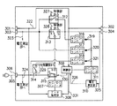
図1は、本発明の第1の実施形態に係る2.1チャンネルのスピーカシステムを示す図である。本図において、101は、オーディオコントローラである。102、103、104はアクティブスピーカであり、フロントレフトスピーカ、フロントライトスピーカ、サブウーファからなる。105は、アクティブスピーカ102〜104から音声を出力するための音源信号であり、例えばCDプレーヤ等から音声コード経由で入力される。106、107、108は、音源信号105を各々のスピーカに伝送するための伝送路であると同時に、通信信号を伝送するための伝送路である。109、113は、ACコンセントから供給されるAC電力を伝送するためのAC電源コード、110、111、112は、機器間にAC電力を伝送するためのACケーブルである。なお、オーディオコントローラ101、アクティブスピーカ102〜104のそれぞれは、本発明の情報処理装置の一適用例となる構成である。
<First Embodiment>
FIG. 1 is a diagram showing a 2.1-channel speaker system according to the first embodiment of the present invention. In this figure, 101 is an audio controller.
図2は、図1のオーディオコントローラ101を詳細に示すブロック図であり、図2において音源信号105、AC電源コード109は図1と同じである。
2 is a block diagram showing in detail the
201は、音源信号105を伝送するための音声コードを本機器に接続するためのコネクタである。
202は、音源信号及び通信信号をアクティブスピーカ102〜104に伝送するためのケーブルを接続するコネクタである。
A
203は、AC電源コード109を接続するためのコネクタ(ACインレット)である。204は、コネクタ203から供給されたAC電力をアクティブスピーカ102〜104に供給するためのコネクタである。また、コネクタ204はアクティブスピーカ102〜104から電力を受給する場合も使用される。尚、コネクタ202と204に接続されるケーブルは図1で説明したように、別々でも構わないが、ここでは一体型とし、コネクタ202、204で分かれているものとして説明する。但し、コネクタ202、204が一つのコネクタで構成されていても構わない。なお、コネクタ203は、請求項1に係る発明の第1の電力受給手段の一適用例となる構成である。また、コネクタ204は、請求項1に係る発明の第2の電力受給手段の一適用例となる構成である。
205は、機器内部の電気部品にDC電力を供給するためのAC/DCコンバータである。206は、音源信号を処理するためのデータ処理部であり、AC/DCコンバータ205から供給されるDC電力で動作する。
Reference numeral 205 denotes an AC / DC converter for supplying DC power to electrical components inside the device.
207は、制御部であり、データ処理部206や機器内部のAC電力の供給・停止を制御する。208は、電圧測定部であり、機器内に供給されているAC電力の電圧を測定する。
209は、DC/DCコンバータであり、制御部207、電圧測定部208にDC電力を供給する。
A DC /
210は、コネクタ203から供給されたAC電力をコネクタ204に供給・停止するためのスイッチであり、一点接点(ON/OFF)方式のリレー等を用いる。
210 is a switch for supplying / stopping the AC power supplied from the
211は、コネクタ203から供給されるAC電力とコネクタ204から供給されるAC電力のどちらかをAC/DCコンバータ205に供給するためのスイッチであり、2点接点方式のリレー等を用いる。
212、213は、AC/DCコンバータであり、DC/DCコンバータ209にDC電力を供給する。214、215は、ダイオードである。ダイオード214、215は、DC/DCコンバータ209に対してコネクタ203から供給されるAC電力とコネクタ204から供給されるAC電力のどちらかを供給する際、AC/DCコンバータ212、213でDC電力化された後の、お互いのDC電流が他方に流れ込まないようにする。
216は、音源信号105を伝送するためのデータ伝送路であると同時に、各機器間で通信を行うための双方向の伝送路である。
217は、AC電源コード109から供給されるAC電力の電圧値を測定するための伝送路である。218は、コネクタ204経由でアクティブスピーカから供給されるAC電力の電圧を測定するための伝送路である。伝送路217、218はそれぞれ電圧測定部208に接続されている。
Reference numeral 217 denotes a transmission path for measuring the voltage value of the AC power supplied from the
219は、電圧測定部208で各AC電力の電圧値を測定した結果を制御部207に送信するための制御線である。
220、221は、それぞれリレー210、211の開閉又は接点の切り替えを制御部207が制御するための制御線である。222は、制御部207がデータ処理部206を制御するための制御線である。
図3は、図1のアクティブスピーカ102、103、104を詳細に示すブロック図である。
FIG. 3 is a block diagram showing in detail the
301は、オーディオコントローラ101から音源信号105を受信するため、又は、他のアクティブスピーカから音源信号105を受信するためのケーブルを接続するコネクタである。302は、他のアクティブスピーカへ音源信号105(及び通信信号)を伝送するためのケーブルを接続するコネクタである。
303は、オーディオコントローラ101又は他のアクティブスピーカからAC電力を供給してもらうため、或いは、オーディオコントローラ101又は他のアクティブスピーカへAC電力を供給するためのケーブルを接続するコネクタである。304は、他のアクティブスピーカからAC電力を供給してもらうため、或いは、他のアクティブスピーカへAC電力を供給するためのケーブルを接続するコネクタである。また、コネクタ303、304を介して接続される装置が本発明の第1の外部装置、第2の外部装置の一例となる。
A
なお、図2と同様、コネクタ301と303、コネクタ302と304にそれぞれ接続されるケーブルは図1に示したように、別々でも構わないが、ここでは一体型とし、コネクタで分かれているもととして説明する。但し、コネクタ301と303、コネクタ302と304がそれぞれ一つのコネクタで構成されていても構わない。
As in FIG. 2, the cables connected to the
305は、AC電源コードであり、ACコンセントから供給される商用電力を伝送する。306は、AC電源コード305を接続するためのコネクタ(ACインレット)である。
307は、機器内部の電気部品にDC電力を供給するためのAC/DCコンバータである。308は、音源信号を処理するためのデータ処理部であり、AC/DCコンバータ307から供給される電力で動作する。
309は、制御部であり、データ処理部308や機器内部のAC電力の供給・停止を制御する。310は電圧測定部であり、機器内のAC電力の電圧を測定する。
311は、DC/DCコンバータであり、制御部309、電圧測定部310にDC電力を供給する。
A DC /
312は、コネクタ303から供給したAC電力をコネクタ304に供給・停止する、またはその逆で、コネクタ304から供給したAC電力をコネクタ303に供給・停止するためのスイッチであり、一点接点(ON/OFF)方式のリレー等を用いる。
313は、コネクタ303又はコネクタ304から供給したAC電力をAC/DCコンバータ307へ供給するために切り替えるためのスイッチであり、2点接点方式のリレー等を用いる。
314は、コネクタ306から供給されたAC電力をコネクタ303、304へ供給・停止するためのスイッチであり、一点接点(ON/OFF)方式のリレー等を用いる。
315は、コネクタ306から供給されるAC電力とコネクタ303又は304から供給されるAC電力のどちらかをAC/DCコンバータ307に供給するためのスイッチであり、2点接点方式のリレー等を用いる。
316、317、318は、AC/DCコンバータであり、DC/DCコンバータ311にDC電力を供給する。319、320、321は、ダイオードであり、DC/DCコンバータ311へコネクタ303、304、306で供給されるAC電力がAC/DCコンバータ316、317、318でDC電力化された後の、お互いの電流が他方に流れ込まないようにする。
322は、音源信号105を伝送するためのデータ伝送路であると同時に、各機器間で通信を行うための双方向の伝送路である。
323は、コネクタ303から供給されるAC電力の電圧値を測定するための伝送路である。324は、コネクタ306から供給されるAC電力の電圧値を測定するための伝送路である。325は、コネクタ304経由でアクティブスピーカから供給されるAC電力の電圧値を測定するための伝送路である。これら3つの伝送路は、電圧測定部310に接続されている。
326は、電圧測定部310で各AC電力の電圧を測定した結果を制御部309に送信するための制御線である。
327、328、329、330はそれぞれ、リレー312、313、314、315の開閉又は接点の切り替えを制御部309が制御するための制御線である。331は、制御部309がデータ処理部308を制御するための制御線である。
なお、図1に示した接続形態において、アクティブスピーカ102、103にはAC電源コード305が接続されていないものとする。また、アクティブスピーカ104はアクティブスピーカ103と接続されているが、もう片方の接続コネクタ(音源信号コネクタ302及びAC電源コネクタ304)には何も接続されていない状態である。
In the connection form shown in FIG. 1, it is assumed that the
表1は、図2で示したオーディオコントローラ101のブロック図において、コネクタ203と204から供給されるAC電力の組み合わせと、リレー210、211の関係を示した表である。表1に示すように、電力供給の組み合わせは全部で4通り(表1の(1)から(4))である。
Table 1 is a table showing the relationship between the combinations of AC power supplied from the

表1において、コネクタ203、204からAC電力が供給される場合を1、供給されていない場合を0で表わしている。また、リレー210の状態は、ONとOFFの2値、リレー211の状態は、a、b、Xの3値で表わされる。
In Table 1, 1 indicates that AC power is supplied from the
ここで、aの状態は、図2に示すように、コネクタ203側に接続された状態である。同様に、bの状態は、コネクタ204側に接続された状態である。
Here, the state a is a state connected to the
Xの状態は、コネクタ203、204から供給されている電力の電圧値の大きさによって状態がa、bのどちらかに時間とともに変わることを意味し、ある時間においてはaかbのどちらかの接点に接触しているものとする。
The state of X means that the state changes to either a or b depending on the magnitude of the voltage value of the power supplied from the
オーディオコントローラ101に電力が供給されていない状態、つまりコネクタ203、204のいずれにもAC電力が供給されていない場合((1)の場合)、リレー210はOFF状態で、リレー211はa側に接続されているとする。
When power is not supplied to the
同様に、コネクタ204のみにAC電力が供給されている場合((2)の場合)は、リレー210はOFF、リレー211はb側に接続される。
Similarly, when AC power is supplied only to the connector 204 (in the case of (2)), the
コネクタ203のみにAC電力が供給されている場合((3)の場合)は、リレー210はON、リレー211はa側に接続される。
When AC power is supplied only to the connector 203 (in the case of (3)), the
コネクタ203、204の両方ともにAC電力が供給されている場合((4)の場合)、リレー210はOFF、リレー211はコネクタ203、204から供給されるAC電力の電圧値の高い方に接続される。つまり、コネクタ203から供給されるAC電力の電圧値の方が高ければa側、コネクタ204から供給されるAC電力の電圧値の方が高ければb側に接続される。
When AC power is supplied to both
表2は、図3で示した、アクティブスピーカのブロック図において、コネクタ303、304、306から供給されるAC電力の組み合わせと、リレー312、313、314、315の関係を示した表である。表2に示す電力供給の組み合わせは全部で8通り(表2の(1)から(8))である。
Table 2 is a table showing the relationship between the combinations of AC power supplied from the
表2において、コネクタ303、304、306からAC電力が供給される場合を1、供給されない場合を0で表わしている。また、リレー312、314の状態は、ONとOFFの2値、リレー313、315の状態は、a、b、Xの3値で表わされる。
In Table 2, the case where AC power is supplied from the
ここで図3に示すとおり、リレー313においてaの状態はコネクタ303側、bの状態はコネクタ304側に接続される。同様に、リレー315においてaの状態はコネクタ306側、bの状態はリレー313側に接続される。Xの状態は、a又はbのどちらかであるが、そのときの条件である各コネクタから供給される電力の電圧値の大きさによって左右され、一義的には決まらない。
Here, as shown in FIG. 3, in the
アクティブスピーカに電力が供給されていない状態の場合((1)の場合)、リレー312の状態はOFF、リレー313の状態はa側、リレー314の状態はOFF、リレー315の状態はa側にそれぞれ接続されているものとする。
When power is not supplied to the active speaker (case (1)), the
次に、コネクタ306のみからAC電力が供給されている場合((2)の場合)、リレー312はON、リレー313はa側、リレー314はON、リレー315はa側にそれぞれ接続される。
Next, when AC power is supplied only from the connector 306 (in the case of (2)), the
コネクタ304のみからAC電力が供給される場合((3)の場合)、リレー312はON、リレー313はb側、リレー314はOFF、リレー315はb側にそれぞれ接続される。
When AC power is supplied only from the connector 304 (in the case of (3)), the
コネクタ304、306からAC電力が供給される場合((4)の場合)、双方の電力の電圧値の大きさによってリレーの接続位置が異なる。コネクタ304の電圧値>コネクタ306の電圧値ならば、リレー312はON、リレー313はb側、リレー314はOFF、リレー315はb側にそれぞれ接続される。逆に、コネクタ304の電圧値<コネクタ306の電圧値ならば、リレー312はOFF、リレー313はa側、リレー314はON、リレー315はa側にそれぞれ接続される。
When AC power is supplied from the
コネクタ303のみからAC電力が供給される場合((5)の場合)、リレー312はON、リレー313はa側、リレー314はOFF、リレー315はb側にそれぞれ接続される。
When AC power is supplied only from the connector 303 (case (5)), the
コネクタ303、306からAC電力が供給される場合((6)の場合)、双方の電力の電圧値の大きさによってリレーの接続位置が異なる。コネクタ303の電圧値>コネクタ306の電圧値ならば、リレー312はON、リレー313はa側、リレー314はOFF、リレー315はb側にそれぞれ接続される。逆に、コネクタ304の電圧値<コネクタ306の電圧値ならば、リレー312はOFF、リレー313はb側、リレー314はON、リレー315はa側にそれぞれ接続される。
When AC power is supplied from the
コネクタ303、304からAC電力が供給される場合((7)の場合)、リレー312はOFF、リレー313は電圧の高いコネクタ側(コネクタ303側の電位の方が高ければa側、コネクタ304側の電位の方が高ければb側)にそれぞれ接続される。また、リレー314はOFF、リレー315はb側にそれぞれ接続される。
When AC power is supplied from the
最後に、コネクタ303、304、306の全てにAC電力が供給されている場合((8)の場合)、各電位の値によってリレーの接続位置が異なる。コネクタ303の電圧値が一番高い場合、リレー313はa側、リレー315はb側に接続される。コネクタ304の電圧値が一番高い場合、リレー313はb側、リレー315はb側に接続される。コネクタ306の電圧値が一番高い場合、リレー313はどちらでも構わないが初期設定がa側なので、a側に接続し((1)の場合の設定が初期設定)、リレー315はa側に接続される。尚、リレー312、314の双方ともどの電圧値が高くてもOFFに接続される。
Finally, when AC power is supplied to all of the
以上のように、各AC電力の電圧値によりリレーを切り替えることにより、オーディオコントローラ101、アクティブスピーカ102〜104のそれぞれにおいて、内部回路に供給されるAC電力として一番電圧値が高い電力が使用されることになる。
As described above, by switching the relay according to the voltage value of each AC power, each of the
図4は、図1におけるオーディオコントローラ101、アクティブスピーカ102〜104の、全ての機器の動作を示すフローチャートである。各機器は、DC/DCコンバータ209又は311がダイオード214、215又は319、320、321経由でAC電力を受けた時点で処理を開始する(ステップS401)。以下に、図2、図3も併せ用いて各機器の処理を詳細に説明する。
FIG. 4 is a flowchart showing the operation of all the devices of the
ステップS402では、図2、図3におけるDC/DCコンバータ回路部209、311は、それぞれのダイオード経由でDC電力が供給され、ACDC電力を制御部207、309、電圧測定部208、310のそれぞれの電源電圧に合ったDC電力に変換する。
In step S402, DC power is supplied to the DC / DC
ステップS403では、各制御部207、309及び各電圧測定部208、310にDC電力が供給される。
In step S403, DC power is supplied to the
ステップS404では、ステップS403で電力供給を受けて起動した各制御部207、309は、それぞれのコネクタ204、303、304にAC電源ケーブルが接続されているかを検出する。なお、この検出部については図示していない。接続検出方法は公知の技術である、コネクタの一部にかかる電圧がケーブルが挿さることにより変化し、各制御部でその電圧値を測定して接続検出する方法等がある。
In step S404, each
ステップS405では、制御部207、309は、不図示の検出部において接続が検出されたか否かを判定する。接続が検出された場合、処理は次のステップS406に進み、接続が検出されなかった場合、処理はステップS418に進み、本フローチャートを終了する。
In step S405, the
ステップS406では、各電圧測定部208、310は、電圧測定のための伝送路217、218、323、324、325を用いて、各コネクタ201、203、204、303、304、306から供給される電力の電圧値を測定する。
In step S406, the
ステップS407では、制御部207、309は、ステップS406の測定の結果、自身のACインレット(203、306)にAC電力が供給されているかどうかを判別する。供給されていれば、処理はステップS408に進み、供給されていなければ、処理はステップS413に進む。
In step S407, the
ステップS408では、制御部207、309は、ステップS406の測定の結果、ACインレット以外から電力が供給されているかどうかを判別する。ACインレット以外から電力が供給されていれば、処理はステップS409に進み、ACインレット以外から電力が供給されていなければ、処理はステップS414に進む。
In step S408, the
ステップS409では、制御部207、309は、ACインレットに供給されたAC電力と他のコネクタから供給されたAC電力とを比較する。ACインレットから供給されたAC電力の電圧値が高ければ、処理はステップS410に進み、そうでなければ、処理はステップS415に進む。
In step S409, the
ステップS410では、制御部207、309は、AC電力の供給を受けている他の機器に対して、そのAC電力の供給の停止と、自装置からAC電力を供給することを通信線216、322を介して要求する。
In step S410, the
ステップS411では、制御部207、309は、ステップS410の要求に対する回答の有無を判定する。回答があれば、処理はステップS412に進み、回答がなければ、処理はステップS410に戻り、要求を繰り返す。
In step S411, the
ステップS412では、制御部207、309は、各リレーを切り替え、他の機器に対してAC電力を供給し、次のステップS418で本フローチャートを終了する。
In step S412, the
ステップS407からステップS413に処理が進んだ場合、ステップS413では、制御部207、309は、他の機器からAC電力の供給を受けられるように各リレーを表1又は表2に則って切り替える。そして、他の機器からAC電力を受給後、ステップS418で本フローチャートを終了する。
When the process proceeds from step S407 to step S413, in step S413, the
ステップS408からステップS414に処理が進んだ場合、ステップS414では、制御部207、309は、他の機器に対してAC電力を供給するように各リレーを表1又は表2に則って切り替える。そして、他の機器に対してAC電力を供給し、ステップS418で本フローチャートを終了する。
When the process proceeds from step S408 to step S414, in step S414, the
ステップS409からステップS415に処理が進んだ場合、ステップS415では、制御部207、309は、他の機器からAC電力の供給を受けられるように各リレーを表1又は表2に則って切り替える。これにより、データ処理部206、308の電力は他の機器から供給されることになる。
When the process proceeds from step S409 to step S415, in step S415, the
ステップS416では、制御部207、309は、他の機器に対して電力供給を続けるように要求する。ステップS417では、制御部207、309は、要求に対する他の機器からの応答の有無を判定する。他の機器からの応答があれば、処理はステップS418に進み、本フローチャートを終了する。一方、他の機器からの応答がなければ、処理はステップS416に戻り、要求を繰り返す。
In step S416, the
図5は、図1に示す2.1チャンネルのスピーカシステムにおいて、各機器が図4に示す処理を終えた後に実行される処理を示すフローチャートである。以下、本処理の詳細を説明する。 FIG. 5 is a flowchart showing processing executed after each device has completed the processing shown in FIG. 4 in the 2.1 channel speaker system shown in FIG. Details of this process will be described below.
本フローチャートのステップS501は、図4に示すフローチャートがステップS418で終了した後に開始される。 Step S501 of this flowchart is started after the flowchart shown in FIG. 4 ends in step S418.
ステップS502では、オーディオコントローラ101、アクティブスピーカ102〜104内の制御部207、309は、電圧測定部208、310から各コネクタから供給されるAC電力の電圧値情報を受ける。
In step S502, the
ステップS503では、制御部207、309は、ステップS502で受けたAC電力の電圧値情報から、複数のコネクタからAC電力が供給されているかどうかを判別する。AC電力が供給されているコネクタが複数あれば、処理はステップS504に進み、そうでなければ、処理はステップS502に戻り繰り返す。
In step S503, the
ステップS504では、制御部207、309は、データ処理部206、308が現在使用しているAC電力の電圧値が他の使用していないAC電力の電圧値よりも高いか否かを判定する。データ処理部206、308が現在使用しているAC電力の電圧値が他の使用していないAC電力の電圧値よりも高い場合、処理はステップS506に進む。データ処理部206、308が現在使用しているAC電力の電圧値が他の使用していないAC電力の電圧値よりも低い場合、処理はステップS505に進む。
In step S504, the
ステップS505では、制御部207、309は、他の使用していないAC電力に切り替えるため、表1又は表2に則って各リレーを切り替える。
In step S505, the
ステップS506では、制御部207、309は、データ処理部206、308が現在使用しているAC電力と、使用していないAC電力との電圧値を比較する。このとき、使用していないAC電力の電圧値は、機器内部のデータ処理部206、308を含めた負荷部が消費する電力量を加味した電圧値で計算するものとする。言い換えれば、使用している電力の電圧値と、使用していない電力の入力電圧値から内部での電圧降下値を減じた値と、の比較を行う。比較した結果、その電圧差分が予め設定した電圧値以上(所定値以上)の差分があり、且つ使用していないAC電力の電圧値の方が低ければ、処理はステップS507に進む。比較した結果、電圧差が所定値以上でなければステップ502に戻る。このようにステップ502からS506の処理を定期的に繰り返す。
In step S506, the
ステップS507では、制御部207、309は、使用していないAC電力の供給元である他の機器に対して電力の供給を停止する旨の電力停止要求を出すとともに、自装置から電力を供給する旨の電力供給要求を出す。ステップS508では、制御部207、309は、ステップS507に対する他の機器からの応答の有無を判定する。他の機器からの応答がなければ、処理はステップS507に戻り、他の機器からの応答があれば、処理はステップS509に進む。
In step S507, the
ステップS509では、制御部207、309は、他の機器に対してAC電力を供給し、ステップS510で本フローチャートを終了する。
In step S509, the
尚、本実施形態では、図2に示す電圧測定部208、図3に示す電圧測定部310によって夫々測定した電圧値を用いて複数の供給電力の切り替えを行っている。但し、電圧値の他に電流値や力率値等を測定し、その値の差によって供給電力の切り替えを行っても構わない。
In the present embodiment, a plurality of power supplies are switched using voltage values measured by the
以上説明したように、各機器は、他の機器へAC電力を供給するか又は他の機器からAC電力を供給される。本実施形態においては、オーディオコントローラ101とアクティブスピーカ104はAC電力がACインレットから供給されている。アクティブスピーカ102、103のそれぞれは、オーディオコントローラ101又はアクティブスピーカ104からAC電力の供給を受ける。この場合、アクティブスピーカ102又は103のどちらかはAC電力を他の機器から受け、その受けたAC電力を他の機器に対して供給しており、図3に示すリレー312をONすることにより、受けたAC電力を他の機器に対して供給している。
As described above, each device supplies AC power to another device or is supplied with AC power from another device. In the present embodiment, AC power is supplied to the
アクティブスピーカ102又は103のもう一方の機器は、他の2つの機器からAC電力の供給を受けることになる。そのとき、図3に示すリレー312はOFF、また、供給されているAC電力のうち、使用するAC電力の方にリレー315のスイッチは接触しており、他の使用していないAC電力は、リレー315のスイッチの接触していない方となる。このように他の機器から複数のAC電力の供給を受けている機器は、図5のフローチャートで示したように、ステップS502からステップS506をループすることにより絶えず複数のAC電力を監視している。2つのAC電力の電圧差が予め決めた電位差よりも拡がった場合には、使用していないAC電力の供給を止めるように他の機器を制御し、逆にその機器に対してAC電力を供給することにより、AC電力を供給する機器、AC電力が供給される機器が入れ替わる。このように本システムにおいては、複数のAC電力が供給される機器は、システムの中で一つだけである。その機器が絶えず複数のAC電力を監視することによって各機器がより高い電圧値のAC電力で動作するようになる。
The other device of the
<第2の実施形態>
次に、本発明の第2の実施形態について説明する。図6は、本発明の他の第2の実施形態に係る電力供給システムの構成を示す図である。2101は、第一のAC電源2107と接続され、デイジーチェーン接続された下位機器に電力を供給する制御器である。2102、2103は、制御器2101とデイジーチェーン接続され、電力の供給を受ける受電機器である。2104、2105は、2102、2103と同様に上位機器から電力の供給を受ける受電機器である。2106は電力を供給するための電力線である。2110は、2102〜2104と同様の受電機器であるが、第二のAC電源2111とも接続される点で異なる。なお、受電機器2110は、本発明の情報処理装置の一適用例となる構成である。なお、受電機器2110の第二のAC電源2111から電力の供給を受ける構成は、請求項1に係る発明の第1の電力受給手段の一適用例となる構成である。なお、電源線2106は、本発明の電力供給手段の一適用例となる構成である。
<Second Embodiment>
Next, a second embodiment of the present invention will be described. FIG. 6 is a diagram showing a configuration of a power supply system according to another second embodiment of the present invention.
図7は、本実施形態に係る電力供給システムの受電機器2110の構成を示すブロック図である。2201は、受電機器2110の制御を行う中央演算装置である。2202は、各ポイントの電圧を検出する電圧検出部である。2203は、受電機器2110の内部の電圧降下値等を記憶するメモリである。2204は、電圧降下値を入力する入力装置である。2205は、上位機器からの入力電力と第二のAC電源の何れかを選択するリレー及び下位機器に供給する電力を選択するリレーをドライブするリレードライバ部である。2206は、上位機器からの入力電力の電圧値を測定する電圧検出A部である。2207は、第二のAC電源の電圧値を測定する電圧検出B部である。
FIG. 7 is a block diagram illustrating a configuration of the
2208は、受電機器2110の内部の駆動電力を供給する内部用電源ユニットである。2209は、入力電力の切り替えを行うリレー接点である。2210は、下位機器への供給電力の切替えを行なうリレー接点である。2211は、下位機器への供給を行う電力の電圧測定ポイント(出力電圧CP)である。2212は、上位機器との接続を行う接続コネクタである。コネクタ2212は、請求項1に係る発明の第2の電力受給手段の一適用例となる構成である。また、内部用電源ユニット2208は、本発明の電力消費系統の一例である。
図8は、本発明の第2の実施形態における動作を示すフローチャートである。図9−1乃至図9−4は、下位機器から供給される電力の電圧値、当該電圧値から受電機器2110の内部の電圧降下値を減じた電圧値、第二のAC電源2111から供給される電力の電圧値、当該電圧値から受電機器2110の内部の電圧降下値を減じた電圧値をグラフで示す図である。図10−1乃至図10−4は、図9−1乃至図9−4に示す各電圧値における電力供給の動作を説明するための図である。表3は、受電機器2110の内部動作電力と下位機器への供給電力の選択方法を一覧にした表である。
FIG. 8 is a flowchart showing the operation in the second embodiment of the present invention. 9A to 9D are voltage values of power supplied from the lower device, a voltage value obtained by subtracting a voltage drop value inside the
以下、これらの図及び表を用いて本発明の第2の実施形態の動作を説明する。図6において、第一のAC電源2107が接続された制御器2101から順にデイジーチェーン接続された下位の受電機器2102〜2105に電力供給を行う。デイジーチェーン接続された受電機器においてもAC電力を接続することができる。この例では、受電機器2110に第二のAC電源2111が接続されている場合について説明する。
Hereinafter, the operation of the second embodiment of the present invention will be described with reference to these drawings and tables. In FIG. 6, power is supplied to the lower
この受電機器2110より下位に接続された受電機器2104、2105は、制御器2101に具備された第一のAC電源2107からの電力と、受電機器2110に接続された第二のAC電源2111からの電力とのどちらも供給可能である。第二のAC電源2111が接続された受電機器2110は、機器内部の動作電力、下位機器2104、2105に供給する電力をそれらの電圧により自由に変更、組み合わせることができる。
The
AC電源が接続されていない受電機器においては、上位機器から供給された電力を内部の動作電力として自機器内で消費し、同一の電力を下位機器に供給することしかできない。 In a power receiving device to which an AC power source is not connected, the power supplied from the host device can be consumed as internal operating power in the device itself, and the same power can only be supplied to the lower device.
受電機器2110の内部動作電力は、上位機器からの供給電力の電圧値と第二のAC電源2111の電圧値とを比較し、高い電圧値の電力を内部動作電力として選択する。下位機器へ供給する電力は、選択された内部動作電力が内部での電圧降下により、内部動作電力として選択されなかった方の電力より電圧が低くなる場合には、内部動作電力として選択されなかった方の電力が選択される。
As the internal operating power of the
ここで各電圧の記号の説明を行う。V1は、上位機器から供給される電力の受電機器2110の入力電圧である。V2は、受電機器2110に接続された第二のAC電源2111の入力電圧である。V0は、受電機器2110内の電圧降下値である。Vaは、上位の受電機器から供給される電力で内部動作を行った場合における、内部の電圧降下値V0を入力電圧V1から減じた受電機器2110の出力電圧である。Vbは、第二のAC電源2111から供給される電力で内部動作を行った場合における、内部の電圧降下値V0を第二のAC電源2111の電圧値V2から減じた受電機器の出力電圧である。電源の組合せを表3に示す。
Here, symbols of each voltage will be described. V1 is an input voltage of the
第二のAC電源2111が接続される受電機器2110のブロック図(図7)において、受電機器2110内部のリレー接点、コイルの直流抵抗、スイッチの接触抵抗、接続電線の抵抗値等と、受電機器2110内部での消費電流量を予め測定しておく。この測定した値から受電機器2110の電圧降下値V0を入力装置2204を用いて予め設定しておく。このデータは中央演算装置2201経由でメモリ2203に蓄積される(ステップS2301)。これにより、受電機器2110内部における電圧降下値が設定される。
In the block diagram (FIG. 7) of the
次に、電圧検出A部2206は、接続コネクタ2212に接続線2106で接続される受電機器から供給される電力の電圧を測定する(ステップS2302)。この電圧値がV1である。中央演算装置2201は、入力電圧値V1から受電機器2110内部での電圧降下値V0を減じた電圧値Vaをメモリ2203に記憶する(ステップS2303)。
Next, the voltage
次に、電圧検出B部2207は、第二のAC電源2111が接続されているか否かを判定する(ステップS2304)。このとき、電圧値がゼロの場合は第二のAC電源2111が接続されていないと判断され、自機器2110を含む下位の受電機器2104、2105は自機器2110の上位の受電機器から供給された電力で動作することになる(ステップS2305)。
Next, the voltage
一方、第二のAC電源2111が接続されていると判定された場合、電圧検出B部2207は、第二のAC電源2111から供給される電力の電圧値(V2)を検出する(ステップS2306)。続いて、中央演算装置2201は、入力電圧値V2から受電機器2110内部での電圧降下値V0を減じた電圧値Vbをメモリ2203に記憶する(ステップS2307)。
On the other hand, when it is determined that the second
次に、受電機器2110の内部で使用する電力、下位の受電機器に供給する電力としてどの電力を使用するかを選択する方法について説明する。
Next, a method of selecting which power is used as the power used inside the
自機器2110内部で使用する電力の選択は、上位機器から供給される電力と第二のAC電源2111から供給される電力のうち電圧の高い方を選択する。以下、その手順について説明する。
The power used in the
まず、電流供給リレーSW100_2213をOFFにしておく。これは、下位の受電機器に電力を供給してしまうと下位機器の負荷により電圧降下が発生してしまうのを避けるとともに、電流が流れることによる危険を回避するためである。 First, the current supply relay SW100_2213 is turned off. This is to avoid a voltage drop due to the load of the lower device when power is supplied to the lower power receiving device, and to avoid danger due to the current flowing.
SW0_2209は、内部に電圧が供給されていない状態では、図7の(1)側に接続され、受電機器2110内部の電圧が供給された後も中央演算装置2201からの制御がない限り保持される回路が付されている。上位機器からの電力供給ケーブル2106がコネクタ2212に接続され、電力が供給される。これに伴い、内部用電源ユニット2208に電力が供給される。受電機器2110は内部用電源ユニット2208から供給される電力で中央演算装置2201等の内部回路の動作を開始する。中央演算装置2201は電圧検出A部2206を駆動させ、上位機器から供給される電力の電圧(V1)を検出し、電圧検出部2202により中央演算装置2201に通知される。
SW0 — 2209 is connected to the (1) side in FIG. 7 in a state in which no voltage is supplied to the inside thereof, and is maintained even after the voltage inside the
次に、第二のAC電源2111の電圧検出を電圧検出B部2207で行う。このとき、SW0_2209は、図7の(1)側に接続した状態で構わない。中央演算装置2201は電圧検出B部2207を駆動させ、第二のAC電源2111から供給される電力の電圧(V2)を検出し、電圧検出部2202により中央演算装置2201に通知される。
Next, the voltage
中央演算装置2201は、電圧検出A部2206及び電圧検出B部2207で検出された電圧を比較する。比較後、電圧の高い方を内部の動作電力として使用する。
The
中央演算装置2201は、上位機器からの入力電圧値V1、第二のAC電源2111からの入力電圧値V2から、受電機器2110の内部の予め設定された電圧降下値V0を減じる。
The
上位機器からの入力電圧値V1から受電機器2110の内部の電圧降下値V0を減じた電圧値をVaとし、AC電源2111からの入力電圧値V2から内部の電圧降下値V0を減じた電圧をVbとする。この値はメモリ2203に蓄積される。Va、Vbは出力電圧CP_2211とすることができる。これら計算された値から下位機器へ供給する電力を選択する。
The voltage value obtained by subtracting the internal voltage drop value V0 of the
各電圧値の高低で下位機器に供給する電力、受電機器2110が内部で使用する電力の動作に関して説明する。中央演算装置2201は、メモリ2203に保持された各電圧V1、V2、Va、Vbがどのような関係にあるかを判定する(ステップS2308)。
The operation of the power supplied to the lower device at each voltage value and the power used internally by the
図9−1に示すように、V1>V2、Va>V2の関係にある場合(ステップS2309)、中央演算装置2201は、受電機器2110内部の使用電力としてV1を使用し、下位機器への供給電力としてVaを供給する。この関係は、上位機器から供給される電力の電圧値V1が第二のAC電源2111から供給される電力の電圧値V2より高い場合で、且つ電圧値V1から受電機器2110内部の電圧降下値V0を減じても、第二のAC電源2111から供給される電圧値V2より電圧値が高い関係にあることを意味する。供給電力を決定した後、中央演算装置2201はSW0_2209、SW1_2210ともに(1)側にセットする(ステップS2310)。このようにすることで、受電機器2110内部で使用する電力の電圧値V1及び下位機器に供給する電力の電圧値V1−V0(=Va)ともに高くすることが可能となる。
As shown in FIG. 9A, when V1> V2 and Va> V2 are satisfied (step S2309), the
このときの具体的な電力の供給について図10−1を用いて説明する。図10−1に示す各電圧の条件は飽くまで一例である。制御器2101に接続された第一のAC電源2107から供給される電力の電圧は100Vである。また、供給された電力の電圧値は、受電機器2110までデイジーチェーン接続された受電機器2102、2103の内部において電圧降下する。よって、受電機器2103から受電機器2110に供給される電力の電圧値V1は99Vとなる。
Specific power supply at this time will be described with reference to FIG. Each voltage condition shown in FIG. 10A is an example until it gets tired. The voltage of power supplied from the first
一方、受電機器2110に接続されたAC電源2111から供給される電力の電圧値(V2)は95Vである。受電機器2110の内部の降下電圧値V0は0.5Vであるため、Vaは98.5V、Vbは94.5Vとなる。よって、受電機器2110における内部の動作電圧はV1、下位機器への供給電力の電圧はVaとなる。
On the other hand, the voltage value (V2) of power supplied from the
また、図9−2に示すように、V1>V2、V2>Vaである場合(ステップS2311)、受電機器2110における内部の動作電圧はV1を使用し、下位機器へは第二のAC電源2111から供給される電圧V2の電力を供給する。この関係は、上位機器から供給される電力の電圧値V1が第二のAC電源2111から供給される電力の電圧値V2より高い場合で、且つ電圧値V1から受電機器2110の内部の電圧降下値V0を減じると、電圧値V2より低くなる関係を意味する。供給電力を決定した後、中央演算装置2201はSW0_2209を(1)側、SW1_2210を(2)側にセットする(ステップS2312)。このようにすることで、受電機器2110内部で使用する電力の電圧値V1及び下位機器に供給する電力の電圧値V2をともに高くすることが可能となる。
Also, as shown in FIG. 9B, when V1> V2 and V2> Va (step S2311), the internal operating voltage in the
このときの具体的な電力の供給について図10−2を用いて説明する。図10−2に示す各電圧の条件は飽くまでも一例である。制御器2101に接続された第一のAC電源2107から供給される電力の電圧は100Vである。また、供給された電力の電圧値は、受電機器2110までデイジーチェーン接続された受電機器2102、2103の内部において電圧降下する。よって、受電機器2103から受電機器2110に供給される電力の電圧値V1は99Vとなる。
Specific power supply at this time will be described with reference to FIG. The conditions of each voltage shown in FIG. 10-2 are just examples. The voltage of power supplied from the first
一方、受電機器2110に接続されたAC電源2111から供給される電力の電圧値(V2)は98Vである。受電機器2110の内部の降下電圧値V0は2.0Vであるため、Vaは97V、Vbは96Vとなる。よって、受電機器2110における内部の動作電圧はV1、下位機器への供給電力の電圧はV2となる。
On the other hand, the voltage value (V2) of power supplied from the
また、図9−3に示すように、V2>V1、V1>Vbである場合(ステップS2313)、受電機器2110における内部の動作電力はV2を使用し、下位機器へはV1の電力を供給する。この関係は、上位機器から供給される電力の電圧値V1が第二のAC電源2111から供給される電力の電圧値V2より低い場合で、且つ電圧値V2から受電機器2110の内部の電圧降下値V0を減じると、電圧値V1より低くなる関係を意味する。供給電力を決定した後、中央演算装置2201はSW0_2209を(2)側、SW1_2210を(1)側にセットする(ステップS2314)。このようにすることで、受電機器2110内部で使用する電力の電圧値V2及び下位機器に供給する電力の電圧値V1をともに高くすることが可能となる。
As shown in FIG. 9C, when V2> V1 and V1> Vb are satisfied (step S2313), the internal operating power in the
このときの具体的な電力の供給について図10−3を用いて説明する。図10−3に示す各電圧の条件は飽くまでも一例である。制御器2101に接続された第一のAC電源2107から供給される電力の電圧は100Vである。また、供給された電力の電圧値は、受電機器2110までデイジーチェーン接続された受電機器2102、2103の内部において電圧降下する。よって、受電機器2103から受電機器2110に供給される電力の電圧値V1は99Vとなる。
Specific power supply at this time will be described with reference to FIG. The conditions of each voltage shown in FIG. 10-3 are just examples. The voltage of power supplied from the first
一方、受電機器2110に接続された第二のAC電源2111から供給される電力の電圧値(V2)は100Vである。受電機器2110の内部の降下電圧値V0は2.0Vであるため、Vaは97V、Vbは98Vとなる。よって、受電機器2110における内部の動作電圧はV2、下位機器への供給電力の電圧はV1となる。
On the other hand, the voltage value (V2) of the power supplied from the second
また、図9−4に示すように、V2>V1、Vb>V1である場合(ステップS2315)、受電機器2110における内部の動作電力はV2を使用し、下位機器へはVbの電力を供給する。この関係は、上位機器から供給される電力の電圧値V1が第二のAC電源2111から供給される電力の電圧値V2より低い場合で、且つ、電圧値V1が、電圧値V2から受電機器2110内部の電圧降下V0を減じた電圧値Vbより低い関係であることを意味する。供給電力を決定した後、中央演算装置2201はSW0_2209、SW1_2210共に図7の(2)側にセットする(ステップS2315)。このようにすることで、受電機器2110内部で使用する電力の電圧値V2及び下位機器に供給する電力の電圧値V2−V0(=Vb)ともに高くすることが可能となる。
As shown in FIG. 9-4, when V2> V1 and Vb> V1 are satisfied (step S2315), V2 is used as the internal operating power in the
このときの具体的な電力供給について、図10−4を用いて説明する。図10−4に示す各電圧の条件は飽くまでも一例である。制御器2101に接続された第一のAC電源2107から供給される電力の電圧は99Vである。また、供給された電力の電圧値は、受電機器2110までデイジーチェーン接続された受電機器2102、2103の内部において電圧降下する。よって、受電機器2103から受電機器2110に供給される電力の電圧値V1は98Vとなる。
Specific power supply at this time will be described with reference to FIG. The conditions of each voltage shown in FIG. 10-4 are just examples. The voltage of the power supplied from the first
一方、受電機器2110に接続された第二のAC電源2111から供給される電力の電圧値(V2)は99Vである。受電機器2110の内部の降下電圧値V0は0.5Vであるため、Vaは97.5V、Vbは98.5Vとなる。よって、受電機器2110における内部の動作電圧はV2、下位機器への供給電力の電圧はVbとなる。
On the other hand, the voltage value (V2) of the power supplied from the second
これらの例は、供給される電力のうち電圧の高い方を受電機器2110内で使用する例を記したが、自機器内は低い方の電力を使用し、下位機器には高い方の電力を供給することも、上述した本実施形態と同様の構成と動作手順で容易に実現できる。
In these examples, the higher voltage of the supplied power is used in the
また、上述の電圧の検出はシステム立上げ時を想定しているが、電圧検出をリアルタイムに行うことも可能であり、電圧の変化、上位機器の消費電流の変化等に柔軟に対応することが可能である。 In addition, although the voltage detection described above is assumed at the time of system startup, it is also possible to perform voltage detection in real time and flexibly respond to changes in voltage, current consumption of higher-level equipment, etc. Is possible.
上述した実施形態においては、伝送路を介して複数の機器から供給される電力のうちの高い方の電圧、又は、伝送路を介して機器から供給される電力とAC電源から供給される電力のうちの高い方を内部で使用するように構成している。従って、伝送路の長さによる電圧降下を考慮した上で最適な電力を使用することが可能となるため、伝送路を介して電力を供給するシステム全体として安定した動作を行うことができる。 In the above-described embodiment, the higher voltage of the power supplied from a plurality of devices via the transmission line, or the power supplied from the device via the transmission line and the power supplied from the AC power source. The higher one is used internally. Therefore, since it is possible to use the optimum power in consideration of the voltage drop due to the length of the transmission line, it is possible to perform a stable operation as a whole system that supplies power through the transmission line.
また、現在内部で使用されている電力が内部での電圧降下により現在内部で使用されていない電力より低くなる場合、内部の電力消費系統を介さずに現在内部で使用されていない電力を下位の機器に供給するように構成している。従って、自装置内で発生した電圧降下の影響を排除した電力を下位の機器に供給することが可能となるため、電力が供給される装置(下位の機器)は安定した動作を行うことができる。 Also, if the power currently used internally is lower than the power that is not currently used internally due to a voltage drop inside, the power that is not currently used internally will be reduced to the lower level without going through the internal power consumption system. It is configured to supply to equipment. Accordingly, since it is possible to supply power to a lower-order device that excludes the influence of a voltage drop that has occurred in the device itself, the device to which power is supplied (lower-order device) can perform a stable operation. .
上述した本発明の実施形態を構成する各手段及び各ステップは、コンピュータのRAMやROM等に記憶されたプログラムが動作することによって実現できる。このプログラム及び前記プログラムを記録したコンピュータ読み取り可能な記録媒体は本発明に含まれる。 Each means and each step constituting the embodiment of the present invention described above can be realized by operating a program stored in a RAM, a ROM, or the like of a computer. This program and a computer-readable recording medium recording the program are included in the present invention.
また、本発明は、例えば、システム、装置、方法、プログラムもしくは記録媒体等としての実施形態も可能であり、具体的には、一つの機器からなる装置に適用してもよい。 Further, the present invention can be implemented as, for example, a system, apparatus, method, program, or recording medium, and may be applied to an apparatus composed of a single device.
なお、本発明は、上述した実施形態の機能を実現するソフトウェアのプログラムを、システム又は装置に直接、又は遠隔から供給する。そして、そのシステム又は装置のコンピュータが前記供給されたプログラムコードを読み出して実行することによっても達成される場合を含む。 The present invention supplies a software program for realizing the functions of the above-described embodiments directly or remotely to a system or apparatus. In addition, this includes a case where the system or the computer of the apparatus is also achieved by reading and executing the supplied program code.
従って、本発明の機能処理をコンピュータで実現するために、前記コンピュータにインストールされるプログラムコード自体も本発明を実現するものである。つまり、本発明は、本発明の機能処理を実現するためのコンピュータプログラム自体も含まれる。その場合、プログラムの機能を有していれば、オブジェクトコード、インタプリタにより実行されるプログラム、OSに供給するスクリプトデータ等の形態であってもよい。 Accordingly, since the functions of the present invention are implemented by computer, the program code installed in the computer also implements the present invention. In other words, the present invention includes a computer program itself for realizing the functional processing of the present invention. In that case, as long as it has the function of a program, it may be in the form of object code, a program executed by an interpreter, script data supplied to the OS, and the like.
また、コンピュータが、読み出したプログラムを実行することによって、前述した実施形態の機能が実現される。更に、そのプログラムの指示に基づき、コンピュータ上で稼動しているOS等が、実際の処理の一部又は全部を行い、その処理によっても前述した実施形態の機能が実現され得る。 Further, the functions of the above-described embodiments are realized by the computer executing the read program. Furthermore, based on the instructions of the program, an OS or the like running on the computer performs part or all of the actual processing, and the functions of the above-described embodiments can be realized by the processing.
更に、その他の方法として、まず記録媒体から読み出されたプログラムが、コンピュータに挿入された機能拡張ボードやコンピュータに接続された機能拡張ユニットに備わるメモリに書き込まれる。そして、そのプログラムの指示に基づき、その機能拡張ボードや機能拡張ユニットに備わるCPU等が実際の処理の一部又は全部を行い、その処理によっても前述した実施形態の機能が実現される。 As another method, a program read from a recording medium is first written in a memory provided in a function expansion board inserted into the computer or a function expansion unit connected to the computer. Then, based on the instructions of the program, the CPU or the like provided in the function expansion board or function expansion unit performs part or all of the actual processing, and the functions of the above-described embodiments are realized by the processing.
101 オーディオコントローラ
102〜104 アクティブスピーカ
105 音源信号
106〜108 伝送路
109、113 AC電源コード
110、111、112 ACケーブル
201〜204 コネクタ
205 AC/DCコンバータ
206 データ処理部
207 制御部
208 電圧測定部
209 DC/DCコンバータ
210、211 スイッチ(リレー)
212、213 AC/DCコンバータ
214、215 ダイオード
216〜218 伝送路
219〜222 制御線
301〜304、306 コネクタ
305 AC電源コード
307 AC/DCコンバータ
308 データ処理部
309 制御部
310 電圧測定部
311 DC/DCコンバータ
312〜315 スイッチ(リレー)
316〜318 AC/DCコンバータ
319〜321 ダイオード
322〜325 伝送路
326〜331 制御線
2101 制御器
2102〜2105、2110 受電機器
2106 電源線
2107 第一のAC電源
2111 第二のAC電源
2201 中央演算装置
2202 電圧検出部
2203 メモリ
2204 入力装置
2205 リレードライバ部
2206 電圧検出A部
2207 電圧検出B部
2208 内部用電源ユニット
2209、2210、2213 リレー接点
2211 電圧測定ポイント
2212 接続コネクタ
DESCRIPTION OF
212, 213 AC /
316 to 318 AC /
Claims (10)
他の情報処理装置から電力の供給を受けるとともに、前記他の情報処理装置に対して電力を供給するための第2のコネクタと、
前記第1のコネクタより供給される電力の電圧値と、前記第2のコネクタより供給される電力の電圧値とを比較する第1の比較手段と、
前記第1の比較手段による比較の結果に従って、前記第1のコネクタより供給される電力と前記第2のコネクタより供給される電力とのうちの何れか一方の電力を内部で使用するように制御する制御手段と、
前記第1のコネクタより供給される電力の電圧値が前記第2のコネクタより供給される電力の電圧値より高い場合、高い電圧値をもつと判定された前記第1のコネクタより供給される電力を前記第2のコネクタを介して前記他の情報処理装置に対して供給する電力供給手段とを有することを特徴とする情報処理装置。 A first connector for receiving power from a power source;
A second connector for receiving power from another information processing apparatus and supplying power to the other information processing apparatus;
First comparison means for comparing a voltage value of power supplied from the first connector and a voltage value of power supplied from the second connector;
According to the result of comparison by said first comparison means, controlling one of the power of the electric power supplied from the power and the second connector to be supplied from the first connector to be used in internal Control means to
Power voltage value of the power supplied from the first connector is supplied from the when the second connector higher than the voltage value of the power supplied from the first connector that is determined to have a high voltage value Power supply means for supplying the other information processing apparatus via the second connector.
前記電力供給手段は、前記第1のコネクタより供給される電力の電圧値が、前記第2のコネクタより前記他の情報処理装置から供給される電力の電圧値より高いと判定された場合、前記第1のコネクタより供給される電力を前記他の情報処理装置に対して供給することを特徴とする請求項1に記載の情報処理装置。 As a result of the comparison by the first comparison means, it is determined that the voltage value of the power supplied from the first connector is higher than the voltage value of the power supplied from the other information processing device from the second connector. A request means for requesting the other information processing apparatus to stop supplying power;
The power supply means, when it is determined that the voltage value of power supplied from the first connector is higher than the voltage value of power supplied from the other information processing device than the second connector, The information processing apparatus according to claim 1, wherein the power supplied from the first connector is supplied to the other information processing apparatus.
前記制御手段による制御によって内部で使用される電力の電圧値から前記判定手段により判定された電圧値を減じた値と、内部で使用されない電力の電圧値とを比較する第2の比較手段とを更に有し、
前記電力供給手段は、前記第2の比較手段による比較の結果に基づいて、内部で使用される電力と、内部で使用されない電力との何れか一方の電力を前記他の情報処理装置に対して供給することを特徴とする請求項1に記載の情報処理装置。 Determination means for determining a voltage drop value due to power being used inside the information processing apparatus;
A value obtained by subtracting the voltage value determined by the determination means from the voltage value of power used internally by the control means, and a second comparison means for comparing the voltage value of power not used internally. In addition,
The power supply means supplies, to the other information processing apparatus, one of power used internally and power not used internally based on a result of comparison by the second comparison means. The information processing apparatus according to claim 1, wherein the information processing apparatus is supplied.
第2の情報処理装置から電力の供給を受けるとともに、前記第2の情報処理装置に対して電力を供給するための第1のコネクタと、
第3の情報処理装置から電力の供給を受けるとともに、前記第3の情報処理装置に対して電力を供給するための第2のコネクタと、
前記第1のコネクタより供給される電力の電圧値と、前記第2のコネクタより供給される電力の電圧値とを比較する第1の比較手段と、
前記第1の比較手段による比較の結果に従って、前記第1のコネクタより供給される電力と前記第2のコネクタより供給される電力とのうちの何れか一方の電力を内部で使用するように制御する制御手段と、
前記第1の比較手段による比較の結果に従って、前記第1のコネクタより供給される電力を前記第3の情報処理装置に対して供給するか、又は、前記第2のコネクタより供給される電力を前記第2の情報処理装置に対して供給する電力供給手段とを有することを特徴とする第1の情報処理装置。 A first information processing apparatus,
A first connector for receiving power from the second information processing apparatus and supplying power to the second information processing apparatus;
A second connector for receiving power from the third information processing apparatus and supplying power to the third information processing apparatus;
First comparison means for comparing a voltage value of power supplied from the first connector and a voltage value of power supplied from the second connector;
According to the result of comparison by said first comparison means, controlling one of the power of the electric power supplied from the power and the second connector to be supplied from the first connector to be used in internal Control means to
According to the result of the comparison by the first comparing means, the power supplied from the first connector is supplied to the third information processing apparatus, or the power supplied from the second connector is supplied. A first information processing apparatus comprising: a power supply unit configured to supply the second information processing apparatus.
前記電力供給手段は、前記第2の比較手段による比較の結果、内部で使用されている電力の電圧値より内部で使用されていない電力の電圧値が所定値以上に低い場合、内部で使用されていない電力を供給している情報処理装置に対して電力の供給を停止するよう要求する要求手段とを更に有し、
前記電力供給手段は、電力の供給が停止された前記情報処理装置に対して電力の供給を開始することを特徴とする請求項5に記載の第1の情報処理装置。 Second comparing means for comparing the voltage value of the power used internally by the control by the control means with the voltage value of the power not used internally;
The power supply means is used internally when the voltage value of power not used internally is lower than a predetermined value than the voltage value of power used internally as a result of comparison by the second comparison means. Requesting means for requesting the information processing apparatus that is not supplying power to stop supplying power;
The first information processing apparatus according to claim 5, wherein the power supply unit starts supplying power to the information processing apparatus for which power supply has been stopped.
前記第1のコネクタより供給される電力の電圧値と、前記第2のコネクタより供給される電力の電圧値とを比較する比較ステップと、
前記比較ステップによる比較の結果に従って、前記第1のコネクタより供給される電力と前記第2のコネクタより供給される電力とのうちの何れか一方の電力を内部で使用するように制御する制御ステップと、
前記第1のコネクタより供給される電力の電圧値が前記第2のコネクタより供給される電力の電圧値より高い場合、高い電圧値をもつと判定された前記第1のコネクタより供給される電力を前記第2のコネクタを介して前記他の情報処理装置に対して供給する電力供給ステップとを含むことを特徴とする情報処理装置の制御方法。 A first connector for receiving power from a power source; and a second connector for receiving power from another information processing apparatus and supplying power to the other information processing apparatus. A method for controlling an information processing apparatus,
A comparison step of comparing a voltage value of power supplied from the first connector with a voltage value of power supplied from the second connector;
According to the result of comparison by the comparing step, control step for controlling to use internally either one of the power of the electric power supplied from the power and the second connector to be supplied from the first connector When,
Power voltage value of the power supplied from the first connector is supplied from the when the second connector higher than the voltage value of the power supplied from the first connector that is determined to have a high voltage value And a power supply step of supplying power to the other information processing apparatus via the second connector.
前記第1のコネクタより供給される電力の電圧値と、前記第2のコネクタより供給される電力の電圧値とを比較する比較ステップと、
前記比較ステップによる比較の結果に従って、前記第1のコネクタより供給される電力と前記第2のコネクタより供給される電力とのうちの何れか一方の電力を内部で使用するように制御する制御ステップと、
前記比較ステップによる比較の結果に従って、前記第1のコネクタより供給される電力を前記第3の情報処理装置に対して供給するか、又は、前記第2のコネクタより供給される電力を前記第2の情報処理装置に対して供給する電力供給ステップとを含むことを特徴とする第1の情報処理装置の制御方法。 While receiving power supply from the second information processing device, receiving power supply from the first connector for supplying power to the second information processing device and the third information processing device, A control method for a first information processing apparatus having a second connector for supplying power to the third information processing apparatus,
A comparison step of comparing a voltage value of power supplied from the first connector with a voltage value of power supplied from the second connector;
According to the result of comparison by the comparing step, control step for controlling to use internally either one of the power of the electric power supplied from the power and the second connector to be supplied from the first connector When,
According to the result of comparison by the comparing step, whether the power supplied from the first connector to supply to said third information processing apparatus, or the power supplied from the second connector the second And a power supply step of supplying power to the information processing apparatus.
Priority Applications (2)
| Application Number | Priority Date | Filing Date | Title |
|---|---|---|---|
| JP2008098599A JP5219593B2 (en) | 2008-04-04 | 2008-04-04 | Information processing apparatus, first information processing apparatus, information processing apparatus control method, first information processing apparatus control method, and program |
| US12/410,619 US8018090B2 (en) | 2008-04-04 | 2009-03-25 | Information processing apparatus and control method |
Applications Claiming Priority (1)
| Application Number | Priority Date | Filing Date | Title |
|---|---|---|---|
| JP2008098599A JP5219593B2 (en) | 2008-04-04 | 2008-04-04 | Information processing apparatus, first information processing apparatus, information processing apparatus control method, first information processing apparatus control method, and program |
Publications (3)
| Publication Number | Publication Date |
|---|---|
| JP2009251891A JP2009251891A (en) | 2009-10-29 |
| JP2009251891A5 JP2009251891A5 (en) | 2011-05-19 |
| JP5219593B2 true JP5219593B2 (en) | 2013-06-26 |
Family
ID=41132599
Family Applications (1)
| Application Number | Title | Priority Date | Filing Date |
|---|---|---|---|
| JP2008098599A Expired - Fee Related JP5219593B2 (en) | 2008-04-04 | 2008-04-04 | Information processing apparatus, first information processing apparatus, information processing apparatus control method, first information processing apparatus control method, and program |
Country Status (2)
| Country | Link |
|---|---|
| US (1) | US8018090B2 (en) |
| JP (1) | JP5219593B2 (en) |
Families Citing this family (7)
| Publication number | Priority date | Publication date | Assignee | Title |
|---|---|---|---|---|
| WO2013018141A1 (en) * | 2011-08-03 | 2013-02-07 | パイオニア株式会社 | Power supply device, audio transmission device, speaker system, speaker, control method for power supply device and program |
| EP2961196B1 (en) * | 2014-06-26 | 2016-09-21 | ams AG | Host interface, accessory interface and method for managing a connection between a host interface and an accessory device |
| US9736567B2 (en) * | 2014-09-29 | 2017-08-15 | Qualcomm Incorporated | Electronics interface for device headset jack |
| JP6877901B2 (en) * | 2016-07-04 | 2021-05-26 | キヤノン株式会社 | Information processing equipment, information processing methods and programs |
| WO2018111977A1 (en) * | 2016-12-13 | 2018-06-21 | Koolbridge Solar, Inc. | Dual-power electrical outlets |
| US10536039B2 (en) | 2017-12-12 | 2020-01-14 | Koolbridge Solar, Inc. | Hybrid wired-wireless communication system for delivery of power from two or more sources to smart appliances |
| JP6620864B1 (en) * | 2018-11-13 | 2019-12-18 | 富士通クライアントコンピューティング株式会社 | Power control apparatus and program |
Family Cites Families (7)
| Publication number | Priority date | Publication date | Assignee | Title |
|---|---|---|---|---|
| JPS58500820A (en) * | 1981-05-27 | 1983-05-19 | マステク、コ−パレイシヤン | Integrated circuit operating method and integrated circuit operating power control circuit |
| JPS63261407A (en) | 1987-04-17 | 1988-10-28 | Mitsubishi Electric Corp | Power supply circuit |
| JP3538480B2 (en) * | 1995-06-28 | 2004-06-14 | 富士通株式会社 | Power supply switching circuit |
| AU2003206744A1 (en) * | 2003-01-17 | 2004-08-13 | Freescale Semiconductor, Inc. | Power management system |
| JP2006042402A (en) * | 2004-07-22 | 2006-02-09 | Seiko Epson Corp | Power control circuit |
| JP2006296126A (en) * | 2005-04-13 | 2006-10-26 | Denso Wave Inc | Charging system, charger, and portable information terminal equipment |
| JP4760465B2 (en) * | 2006-03-17 | 2011-08-31 | 日産自動車株式会社 | Power converter |
-
2008
- 2008-04-04 JP JP2008098599A patent/JP5219593B2/en not_active Expired - Fee Related
-
2009
- 2009-03-25 US US12/410,619 patent/US8018090B2/en not_active Expired - Fee Related
Also Published As
| Publication number | Publication date |
|---|---|
| US20090251003A1 (en) | 2009-10-08 |
| US8018090B2 (en) | 2011-09-13 |
| JP2009251891A (en) | 2009-10-29 |
Similar Documents
| Publication | Publication Date | Title |
|---|---|---|
| JP5219593B2 (en) | Information processing apparatus, first information processing apparatus, information processing apparatus control method, first information processing apparatus control method, and program | |
| EP3382502B1 (en) | Power supplying apparatus and method therefor | |
| KR101017774B1 (en) | Method and system for controlling an array of point-of-load regulators and auxiliary devices | |
| US7000125B2 (en) | Method and system for controlling and monitoring an array of point-of-load regulators | |
| JP6176497B2 (en) | Control device for switching current and electronic device | |
| US20130015714A1 (en) | Smart Power Portal | |
| US20080052551A1 (en) | System For Controlling An Array Of Point-Of-Load Regulators And Auxiliary Devices | |
| US8248031B2 (en) | Method for prioritizing load consumption within a notebook computer | |
| US11507165B2 (en) | Intelligent power module | |
| CN105981478B (en) | Power distributor for variable number of loads and power distribution method | |
| JP2006507624A (en) | Power and network connection configuration for mobile devices | |
| WO2011112379A2 (en) | External power source voltage drop compensation for portable devices | |
| JP2012085467A (en) | Charging apparatus and method of charging | |
| CN112189305A (en) | Audio amplifier assembly, process, and method | |
| US20160179153A1 (en) | Systems and methods for automatic detection of a device | |
| TW201222228A (en) | Power supply circuit, power supply method, and signal processing apparatus | |
| JP5058083B2 (en) | Interface device | |
| CN105576753A (en) | Information processing method and electronic equipment | |
| US8212412B1 (en) | Energy storage connection system | |
| JP4503485B2 (en) | Power management for digital devices | |
| JP2014048880A (en) | Portable battery device | |
| JP2007233719A (en) | Usb system, usb host, and usb device | |
| JP2008043038A (en) | Mobile terminal device | |
| JP2011176904A (en) | Distributed power supply system, control method, program, and recording medium | |
| KR20190125724A (en) | Interface for testing semiconductor devices |
Legal Events
| Date | Code | Title | Description |
|---|---|---|---|
| A521 | Request for written amendment filed |
Free format text: JAPANESE INTERMEDIATE CODE: A523 Effective date: 20110404 |
|
| A621 | Written request for application examination |
Free format text: JAPANESE INTERMEDIATE CODE: A621 Effective date: 20110404 |
|
| A977 | Report on retrieval |
Free format text: JAPANESE INTERMEDIATE CODE: A971007 Effective date: 20120621 |
|
| A131 | Notification of reasons for refusal |
Free format text: JAPANESE INTERMEDIATE CODE: A131 Effective date: 20120626 |
|
| A521 | Request for written amendment filed |
Free format text: JAPANESE INTERMEDIATE CODE: A523 Effective date: 20120719 |
|
| TRDD | Decision of grant or rejection written | ||
| A01 | Written decision to grant a patent or to grant a registration (utility model) |
Free format text: JAPANESE INTERMEDIATE CODE: A01 Effective date: 20130205 |
|
| A61 | First payment of annual fees (during grant procedure) |
Free format text: JAPANESE INTERMEDIATE CODE: A61 Effective date: 20130305 |
|
| FPAY | Renewal fee payment (event date is renewal date of database) |
Free format text: PAYMENT UNTIL: 20160315 Year of fee payment: 3 |
|
| R151 | Written notification of patent or utility model registration |
Ref document number: 5219593 Country of ref document: JP Free format text: JAPANESE INTERMEDIATE CODE: R151 |
|
| FPAY | Renewal fee payment (event date is renewal date of database) |
Free format text: PAYMENT UNTIL: 20160315 Year of fee payment: 3 |
|
| LAPS | Cancellation because of no payment of annual fees |