JP5127800B2 - Motor control device - Google Patents
Motor control device Download PDFInfo
- Publication number
- JP5127800B2 JP5127800B2 JP2009217225A JP2009217225A JP5127800B2 JP 5127800 B2 JP5127800 B2 JP 5127800B2 JP 2009217225 A JP2009217225 A JP 2009217225A JP 2009217225 A JP2009217225 A JP 2009217225A JP 5127800 B2 JP5127800 B2 JP 5127800B2
- Authority
- JP
- Japan
- Prior art keywords
- command
- control
- current
- axis
- motor
- Prior art date
- Legal status (The legal status is an assumption and is not a legal conclusion. Google has not performed a legal analysis and makes no representation as to the accuracy of the status listed.)
- Active
Links
Images


Classifications
-
- H—ELECTRICITY
- H02—GENERATION; CONVERSION OR DISTRIBUTION OF ELECTRIC POWER
- H02P—CONTROL OR REGULATION OF ELECTRIC MOTORS, ELECTRIC GENERATORS OR DYNAMO-ELECTRIC CONVERTERS; CONTROLLING TRANSFORMERS, REACTORS OR CHOKE COILS
- H02P21/00—Arrangements or methods for the control of electric machines by vector control, e.g. by control of field orientation
- H02P21/24—Vector control not involving the use of rotor position or rotor speed sensors
- H02P21/26—Rotor flux based control
-
- H—ELECTRICITY
- H02—GENERATION; CONVERSION OR DISTRIBUTION OF ELECTRIC POWER
- H02P—CONTROL OR REGULATION OF ELECTRIC MOTORS, ELECTRIC GENERATORS OR DYNAMO-ELECTRIC CONVERTERS; CONTROLLING TRANSFORMERS, REACTORS OR CHOKE COILS
- H02P21/00—Arrangements or methods for the control of electric machines by vector control, e.g. by control of field orientation
- H02P21/14—Estimation or adaptation of machine parameters, e.g. flux, current or voltage
-
- H—ELECTRICITY
- H02—GENERATION; CONVERSION OR DISTRIBUTION OF ELECTRIC POWER
- H02P—CONTROL OR REGULATION OF ELECTRIC MOTORS, ELECTRIC GENERATORS OR DYNAMO-ELECTRIC CONVERTERS; CONTROLLING TRANSFORMERS, REACTORS OR CHOKE COILS
- H02P27/00—Arrangements or methods for the control of AC motors characterised by the kind of supply voltage
- H02P27/04—Arrangements or methods for the control of AC motors characterised by the kind of supply voltage using variable-frequency supply voltage, e.g. inverter or converter supply voltage
-
- H—ELECTRICITY
- H02—GENERATION; CONVERSION OR DISTRIBUTION OF ELECTRIC POWER
- H02P—CONTROL OR REGULATION OF ELECTRIC MOTORS, ELECTRIC GENERATORS OR DYNAMO-ELECTRIC CONVERTERS; CONTROLLING TRANSFORMERS, REACTORS OR CHOKE COILS
- H02P21/00—Arrangements or methods for the control of electric machines by vector control, e.g. by control of field orientation
- H02P21/14—Estimation or adaptation of machine parameters, e.g. flux, current or voltage
- H02P21/18—Estimation of position or speed
-
- H—ELECTRICITY
- H02—GENERATION; CONVERSION OR DISTRIBUTION OF ELECTRIC POWER
- H02P—CONTROL OR REGULATION OF ELECTRIC MOTORS, ELECTRIC GENERATORS OR DYNAMO-ELECTRIC CONVERTERS; CONTROLLING TRANSFORMERS, REACTORS OR CHOKE COILS
- H02P2203/00—Indexing scheme relating to controlling arrangements characterised by the means for detecting the position of the rotor
- H02P2203/03—Determination of the rotor position, e.g. initial rotor position, during standstill or low speed operation
-
- H—ELECTRICITY
- H02—GENERATION; CONVERSION OR DISTRIBUTION OF ELECTRIC POWER
- H02P—CONTROL OR REGULATION OF ELECTRIC MOTORS, ELECTRIC GENERATORS OR DYNAMO-ELECTRIC CONVERTERS; CONTROLLING TRANSFORMERS, REACTORS OR CHOKE COILS
- H02P2207/00—Indexing scheme relating to controlling arrangements characterised by the type of motor
- H02P2207/05—Synchronous machines, e.g. with permanent magnets or DC excitation
Description
本発明は、永久磁石モータのロータに配置される低保磁力の永久磁石の磁化状態を、電機子反作用磁界により調整できる手段を備えたモータ制御装置に関する。 The present invention relates to a motor control device including means capable of adjusting a magnetization state of a low coercive force permanent magnet disposed in a rotor of a permanent magnet motor by an armature reaction magnetic field.
近年、洗濯機においては、ダイレクトドライブ方式の永久磁石モータと、ベクトル制御を採用したモータ制御装置との組み合わせにより、モータの制御精度や洗濯性能の向上を図ると共に、消費電力の低減や洗濯運転中の振動低減などの効果が得られている。従来の一般的な制御方式では、脱水運転等でモータを高速回転させる場合はトルクに寄与しないd軸電流Idを通電してモータの誘起電圧を減少させる弱め界磁制御を行っている。この場合、脱水運転ではトルクに寄与しない電流を常時流すことで銅損を増加させており、効率の低下を招いている。 In recent years, in washing machines, the combination of a direct drive type permanent magnet motor and a motor control device employing vector control has improved motor control accuracy and washing performance, while reducing power consumption and during washing operations. The effect of reducing vibration is obtained. In the conventional general control method, when the motor is rotated at a high speed in a dehydrating operation or the like, field weakening control is performed in which a d-axis current Id that does not contribute to torque is supplied to reduce the induced voltage of the motor. In this case, the copper loss is increased by constantly flowing a current that does not contribute to the torque in the dehydration operation, resulting in a decrease in efficiency.
これに対し、特許文献1に開示されている技術では、保磁力が低い永久磁石にd軸電流を一瞬流すことで不可逆的に減磁現象を起こさせて、永久磁石の磁束を減少させてモータの巻線に発生する誘起電圧を減少させ、d軸電流を常時通電することなく高速運転を可能としている。
On the other hand, in the technique disclosed in
特許文献1では、ロータの位置を検出するためにレゾルバを備えている。しかしながら、家電機器などのようにコストが重視される製品では、レゾルバのように高価な位置検出器を用いることが困難であり、位置センサレス制御を採用するものが一般的である。位置センサレス制御としては、一般的にモータの誘起電圧とロータ位置との関係を用いて位置推定を行う方式がある。
In
例えば(1)式のd軸電圧方程式を変形した(2)式の左辺,d軸誘起電圧Edをゼロにするように(3)式でPI補償演算を行い、モータ速度ωを推定し、(4)式によるωの積分からロータ位置θを推定する。 For example, a PI compensation calculation is performed by the expression (3) so that the left side of the d-axis voltage equation of the expression (1), the left side of the expression (2), and the d-axis induced voltage Ed is zero, and the motor speed ω is estimated. 4) Estimate the rotor position θ from the integral of ω according to equation (4).
Vd=R・Id―ωLq・Iq+Ed …(1)
Ed=Vd−R・Id+ω・Lq・Iq …(2)
ω=ω0−Ed・(Kp+1/s・Ki) …(3)
θ=1/s・ω …(4)
尚、(3)式におけるω0は、演算周期において前回に演算されたモータ速度ωであり、sは微分演算子、Kp,Kiは、PI制御におけるゲインである。
Vd = R · Id−ωLq · Iq + Ed (1)
Ed = Vd−R · Id + ω · Lq · Iq (2)
ω = ω0−Ed · (Kp + 1 / s · Ki) (3)
θ = 1 / s · ω (4)
In Equation (3), ω0 is the motor speed ω previously calculated in the calculation cycle, s is a differential operator, and Kp and Ki are gains in PI control.
ここで、(2)式の演算にはd軸電流Id,d軸電圧Vdが含まれている。そして、永久磁石の磁束を変化させるために増減磁通電を行う場合は、d軸電流をパルス状に通電するのでd軸電流Id及びd軸電圧Vdが急激に変化する。また、磁束を変化させるため通電は、モータの回転制御中に行うのが効率的であるため、この時の電流変化率は、数ms〜数10msの間にモータ定格電流の2〜3倍程度の大きさとなる。 Here, the calculation of equation (2) includes the d-axis current Id and the d-axis voltage Vd. When increasing / decreasing energization is performed to change the magnetic flux of the permanent magnet, the d-axis current is applied in a pulsed manner, so that the d-axis current Id and the d-axis voltage Vd change rapidly. In addition, since it is efficient to energize the motor during rotation control to change the magnetic flux, the current change rate at this time is about 2 to 3 times the motor rated current during several ms to several tens of ms. It becomes the size of.
このように、増減磁電流をモータの回転中に通電するには、短い時間内で急激に電流波形の立ち上げと立ち下げとを行う必要がある。一般にモータ電流の制御にもPI制御が用いられることが多い。その場合、d軸電流Idの制御は、(5)式のようにd軸電流指令Id_refと検出したd軸電流Idの偏差であるId_devを演算し、(6)式でPI補償することでd軸電圧指令Vd_refを算出する。
Id_dev=Id_ref−Id …(5)
Vd_ref=Id_dev・(Kp+1/s・Ki) …(6)
As described above, in order to energize the increasing / decreasing magnetic current while the motor is rotating, it is necessary to suddenly raise and lower the current waveform within a short time. In general, PI control is often used to control motor current. In this case, the control of the d-axis current Id is performed by calculating Id_dev which is a deviation between the d-axis current command Id_ref and the detected d-axis current Id as shown in the equation (5) and performing PI compensation by the equation (6). A shaft voltage command Vd_ref is calculated.
Id_dev = Id_ref−Id (5)
Vd_ref = Id_dev · (Kp + 1 / s · Ki) (6)
しかし、上記の制御系は、通常のモータ制御を想定したものであるため、短時間内に増減磁通電を行った場合には、PI制御でその変化に追従させることは難しい。実際にPI制御によってd軸電流の制御を行うと、発散しない程度に制御ゲインを上げた状態であっても、図11に示すように電流指令Id_refに対してd軸電流Idが遅れてしまう。このような遅れが生じると適正な位置で増減磁電流が通電できず、永久磁石の磁束量を所期通りに変化させることができなくなってしまう。 However, since the above control system assumes normal motor control, it is difficult to make the PI control follow the change when increasing / decreasing energization is performed within a short time. When the d-axis current is actually controlled by the PI control, the d-axis current Id is delayed with respect to the current command Id_ref as shown in FIG. 11 even when the control gain is increased to such an extent that it does not diverge. When such a delay occurs, the increasing / decreasing magnetic current cannot be applied at an appropriate position, and the amount of magnetic flux of the permanent magnet cannot be changed as expected.
本発明は上記事情に鑑みてなされたもので、その目的は、位置センサレス方式で永久磁石モータを制御すると共に、永久磁石の磁束を変化させるために通電を行う構成において、増減磁電流を遅れ無しに通電できるモータ制御装置を提供することにある。 The present invention has been made in view of the above circumstances, and its object is to control the permanent magnet motor in a position sensorless manner and to increase or decrease the magnetizing current without delay in a configuration in which energization is performed to change the magnetic flux of the permanent magnet. It is in providing the motor control apparatus which can supply with electricity.
上記目的を達成するため、請求項1記載のモータ制御装置は、複数の半導体スイッチング素子を複数相接続して構成され、直流電源と、着磁量を変更可能な程度に低保磁力である永久磁石がロータに複数配置される永久磁石モータの巻線との間に接続されるインバータ回路と、
前記永久磁石モータについて成立する電圧方程式に基づいて、前記ロータの回転位置を推定する位置推定手段と、
前記推定された回転位置に基づいてd軸電流及びq軸電流を演算し、前記永久磁石モータを制御するために与えられるd軸電流指令及びq軸電流指令と、前記演算結果との差分をPI制御してd軸電圧指令及びq軸電圧指令を生成出力し、前記永久磁石モータをベクトル制御するベクトル制御手段と、
前記インバータ回路を介して前記モータの巻線に通電を行うことで、前記永久磁石を着磁する着磁制御手段と、
この着磁制御手段が前記永久磁石を着磁するために着磁電流を通電する期間において、前記ベクトル制御における電流指令に基づく制御と、前記電流指令に替えて電圧指令を直接出力する制御とを切り替える制御指令切替え手段とを備えたことを特徴とする。
In order to achieve the above object, a motor control device according to
Position estimation means for estimating the rotational position of the rotor based on a voltage equation established for the permanent magnet motor;
A d-axis current and a q-axis current are calculated based on the estimated rotational position, and a difference between the d-axis current command and the q-axis current command given to control the permanent magnet motor and the calculation result is PI. A vector control means for controlling and generating and outputting a d-axis voltage command and a q-axis voltage command, and vector-controlling the permanent magnet motor;
Magnetization control means for magnetizing the permanent magnet by energizing the winding of the motor via the inverter circuit;
In the period in which the magnetization control means energizes the magnetizing current to magnetize the permanent magnet, the control based on the current command in the vector control and the control to directly output the voltage command instead of the current command Control command switching means for switching is provided.
請求項1記載のモータ制御装置によれば、ベクトル制御にPI制御が組み込まれている制御系において、着磁制御を行う期間に突発的に大きな電流が流れた場合でも、制御指令切替え手段が、ベクトル制御における電流指令に基づく制御を、その電流指令に替えて電圧指令を直接出力する制御に切り替えるので、増減磁電流を遅れ無しに通電することができる。 According to the motor control device of the first aspect, in the control system in which the PI control is incorporated in the vector control, even when a large current suddenly flows during the period of performing the magnetization control, the control command switching means is Since the control based on the current command in the vector control is switched to the control that directly outputs the voltage command instead of the current command, the increasing / decreasing magnetic current can be energized without delay.
(第1実施例)
以下、第1実施例について図1ないし図9を参照して説明する。図7は、永久磁石モータ1(アウタロータ型ブラシレスモータ)のロータの構成を示す平面図である。永久磁石モータ1は、ステータ2と、これの外周に設けたロータ3とから構成されている。ステータ2は、ステータコア4とステータ巻線5とから構成されている。ステータコア4は、打ち抜き形成した軟磁性体であるケイ素鋼板を多数枚積層し、かしめて構成したもので、環状のヨーク部4aと、当該ヨーク部4aの外周部から放射状に突出する多数のティース部4bとを有している。ステータコア4の表面は、各ティース部4bの先端面を除き、PET樹脂(モールド樹脂)により覆われている。
また、このPET樹脂から成る複数の取付部6が、ステータ2の内周部に一体的に成形されている。これら取付部6には複数のねじ穴6aが設けられており、これら取付部6をねじ止めすることで、ステータ2が、この場合、ドラム式洗濯乾燥機21の水槽25(図9参照)の背面に固着される。ステータ巻線5は三相からなり、各ティース部4bに巻装されている。
(First embodiment)
The first embodiment will be described below with reference to FIGS. FIG. 7 is a plan view showing the configuration of the rotor of the permanent magnet motor 1 (outer rotor type brushless motor). The
A plurality of mounting portions 6 made of this PET resin are integrally formed on the inner peripheral portion of the
ロータ3は、フレーム7とロータコア8と複数の永久磁石9とを図示しないモールド樹脂により一体化した構成となっている。フレーム7は、磁性体である例えば鉄板をプレス加工することにより扁平な有底円筒状に形成したものである。ロータコア8は、ほぼ環状に打ち抜き形成した軟磁性体であるケイ素鋼板を多数枚積層してかしめて構成したもので、フレーム7の内周部に配置されている。このロータコア8の内周面(ステータ2の外周面(ステータコア4の外周面)と対向し当該ステータ2との間に空隙を形成する面)は、内方に向けて円弧状に突出する複数の凸部(磁極チップ)8aを有した凹凸状に形成されている。
The
これら複数の凸部8aの内部には、ロータコア8を軸方向(ケイ素鋼板の積層方向)に貫通する矩形状の挿入穴が形成されており、これら複数の挿入穴がロータコア8において環状に配置された構成となっている。永久磁石9は、挿入穴に挿入された矩形状のネオジム磁石9a(高保磁力永久磁石)と、同じく矩形状のアルニコ磁石9b(低保磁力永久磁石)とから構成されている。この場合、ネオジム磁石9aの保磁力は約900kA/m、アルニコ磁石9bの保磁力は約100kA/mであり、保磁力が9倍程度異なっている。永久磁石9は全数48であり、それらの内6個がアルニコ磁石9bであり、42個がネオジム磁石9aとなっている。
A rectangular insertion hole that penetrates the
図7では、アルニコ磁石9bが配置されている位置にA〜Fを付しており、A−B間に配置されているネオジム磁石9aは5個,B−C間に配置されているネオジム磁石9aは9個,C−D間に配置されているネオジム磁石9aは5個,D−E間に配置されているネオジム磁石9aは9個,E−F間に配置されているネオジム磁石9aは5個,F−A間に配置されているネオジム磁石9aは9個となっている。この配置形態は、同じ相について発生する誘起電圧の平均値を何れも同じ値にすることで、コギングトルクの発生を抑制するようにしたものである。そして、永久磁石モータ1は、48極/36スロット構成となっており、3スロット当たりでは4極が対応する(4極/3スロット)。
尚、ネオジム磁石9aが高保磁力であり、アルニコ磁石9bが低保磁力であるというのは、後述するようにステータ2を介して着磁電流を通電した場合に、アルニコ磁石9bの着磁量を変化させることができる程度の電流ではネオジム磁石9aの着磁量が変化しないという基準において、前者を高保磁力,後者を低保磁力と称している。
In FIG. 7, A to F are attached to the positions where the
The
次に、上記のように構成された永久磁石モータ1を備えたドラム式洗濯乾燥機21の構成について説明する。図8は、ドラム式洗濯乾燥機21の内部構成を概略的に示す縦断側面図である。ドラム式洗濯乾燥機21の外殻を形成する外箱22は、前面に円形状に開口する洗濯物出入口23を有しており、この洗濯物出入口23は、ドア24により開閉される。外箱22の内部には、背面が閉鎖された有底円筒状の水槽25が配置されており、この水槽25の背面中央部には上述の永久磁石モータ1(ステータ2)がねじ止めにより固着されている。この永久磁石モータ1の回転軸26は、後端部(図8では右側の端部)が永久磁石モータ1(ロータ3)の軸取付部10に固定されており、前端部(図8では左側の端部)が水槽25内に突出している。
Next, the structure of the drum type washing / drying
回転軸26の前端部には、背面が閉鎖された有底円筒状のドラム27が水槽25に対して同軸状となるように固定されており、このドラム27は、永久磁石モータ1の駆動によりロータ3および回転軸26と一体的に回転する。なお、ドラム27には、空気および水を流通可能な複数の流通孔28と、ドラム27内の洗濯物の掻き上げやほぐしを行うための複数のバッフル29が設けられている。水槽25には給水弁30が接続されており、当該給水弁30が開放されると、水槽25内に給水される。また、水槽25には排水弁31を有する排水ホース32が接続されており、当該排水弁31が開放されると、水槽25内の水が排出される。
A bottomed
水槽25の下方には、前後方向へ延びる通風ダクト33が設けられている。この通風ダクト33の前端部は前部ダクト34を介して水槽25内に接続されており、後端部は後部ダクト35を介して水槽25内に接続されている。通風ダクト33の後端部には、送風ファン36が設けられており、この送風ファン36の送風作用により、水槽25内の空気が、矢印で示すように、前部ダクト34から通風ダクト33内に送られ、後部ダクト35を通して水槽25内に戻される。
A
通風ダクト33内部の前端側には蒸発器37が配置されており、後端側には凝縮器38が配置されている。これら蒸発器37および凝縮器38は、コンプレッサ39および絞り弁40とともにヒートポンプ41を構成しており(図9参照)、通風ダクト33内を流れる空気は、蒸発器37により除湿され凝縮器38により加熱されて、水槽25内に循環される。絞り弁40は膨張弁から成り、開度調整機能を有している。
An
外箱22の前面にはドア24の上方に位置して操作パネル42が設けられており、この操作パネル42には運転コースなどを設定するための複数の操作スイッチ(図示せず)が設けられている。操作パネル42は、マイクロコンピュータを主体として構成されドラム式洗濯乾燥機21の運転全般を制御する制御回路部(図示せず)に接続されており、当該制御回路部は、操作パネル42を介して設定された内容に従って、永久磁石モータ1、給水弁30、排水弁31、コンプレッサ39、絞り弁40などの駆動を制御しながら各種の運転コースを実行する。また、図示しないが、コンプレッサ39を構成するコンプレッサモータも、永久磁石モータ1と同様の構成を採用している。
An
図1は、永久磁石モータ1の回転をベクトル制御するモータ制御装置50の構成をブロック図で示したものである。尚、上記コンプレッサモータも同様の構成によって制御される。ベクトル制御では、電機子巻線に流れる電流を、界磁である永久磁石の磁束方向と、それに直交する方向とに分離してそれらを独立に調整し、磁束と発生トルクとを制御する。電流制御には、モータ1のロータと共に回転する座標系、いわゆるd−q座標系で表わした電流値が用いられるが、d軸はロータに取り付けた永久磁石の作る磁束方向であり、q軸はd軸に直交する方向である。巻線に流れる電流のq軸成分であるq軸電流Iqは回転トルクを発生させる成分であり(トルク成分電流)、同d軸成分であるd軸電流Idは磁束を作る成分である(励磁または磁化成分電流)。
FIG. 1 is a block diagram showing the configuration of a
電流センサ51(U,V,W)は、モータ1の各相(U相、V相、W相)に流れる電流Iu,Iv,Iwを検出するセンサである。尚、電流センサ51(電流検出手段)に替えて、インバータ回路52(駆動手段)を構成する下アーム側のスイッチング素子とグランドとの間に3個のシャント抵抗を配置し、それらの端子電圧に基づいて電流Iu,Iv,Iwを検出する構成としても良い。
電流センサ51により検出された電流Iu,Iv,Iwは、A/D変換器53によりA/D変換されるとuvw/dq座標変換器54により2相電流Iα,Iβに変換された後、更にd軸電流Id,q軸電流Iqに変換される。α,βは、モータ1のステータに固定された2軸座標系の座標軸である。ここでの座標変換の計算には、速度・位置推定部54により推定されるロータの回転位置推定値(α軸とd軸との位相差の推定値)θが用いられる。
The current sensor 51 (U, V, W) is a sensor that detects currents Iu, Iv, Iw flowing in the phases (U phase, V phase, W phase) of the
The currents Iu, Iv, Iw detected by the current sensor 51 are converted into two-phase currents Iα, Iβ by the uvw / dq coordinate
速度・位置推定部(位置推定手段)55は、内部にEd演算器56,比例積分器57,減算器58,遅延器59及び積分器60を備えている。Ed演算器56は、前述した(2)式によりd軸誘起電圧Edを演算し、比例積分器57は、d軸誘起電圧Edに対して比例積分演算を施して減算器58に減算値として出力する。減算器58の出力は、1演算周期分の遅延を付与する遅延器59を介して被減算値としてフィードバックされると共に、積分器60に出力される。そして、減算器58の出力がモータ1の回転速度(角速度)ωとなり、積分器60の出力が回転位置θとなる。
The speed / position estimation unit (position estimation means) 55 includes an
着磁制御部61は、洗濯乾燥機21の運転を制御する制御回路部(上位システム)より与えられる運転シーケンス信号を参照して、洗い,脱水,すすぎ,乾燥等の運転状態の変化に従い、永久磁石モータ1のロータ3に配置されているアルニコ磁石9bを着磁するための着磁指令(増磁指令又は減磁指令)を位置推定補正部(補正手段)62及び着磁制御切替え部(制御指令切替え手段)63に出力する。
位置推定補正部62は、着磁制御部61より着磁指令が与えられると、速度・位置推定部55に対してEd保持指令を出力する。速度・位置推定部55は、Ed保持指令が与えられると、Ed演算器56より出力されるd軸誘起電圧Edの値を、その時点で得ている値に保持する。
The
The position estimation correction unit 62 outputs an Ed hold command to the speed /
着磁制御切替え部63には、着磁制御部61より上記着磁指令と共に増減磁電流値が与えられており、また、uvw/dq座標変換器54よりd軸電流Idが与えられている。そして、着磁制御切替え部63は、電流制御器67の比例積分器69dに対し、制御切替え指令と、d軸電圧指令Vd_refとを出力する。
The magnetization control switching unit 63 is given an increase / decrease magnetizing current value together with the magnetization command from the
上記制御回路部より与えられる回転数指令値ω_refは、速度制御部64の減算器65において回転速度ωとの差が求められると、その差が比例積分器66で比例積分演算され、q軸電流指令値Iq_refとして電流制御部67に出力される。Id指令出力部68は、上記制御回路部より与えられる運転シーケンス信号を参照し、弱め界磁制御を行う必要がある場合は、電流制御部67に出力するd軸電流指令値Id_refを負の値に設定し、それ以外の場合は、d軸電流指令値Id_refを「0」に設定する。
When the difference between the rotational speed command value ω_ref given by the control circuit unit and the rotational speed ω is obtained by the
電流制御部67では、減算器69d,69qにおいてd軸電流指令値Id_ref,q軸電流指令値Iq_refとd軸電流Id,q軸電流Iqとの差がそれぞれ求められ、その差が比例積分器70d,70qで比例積分演算される。そして、比例積分演算の結果は、d−q座標系で表わされた出力電圧指令値Vd,Vqとして、dq/uvw座標変換器71に出力される。
In the
ここで、図2は、比例積分器70dの内部構成を示す。減算器69dの減算結果は、比例器72及び積分器73に入力される。そして、比例器72,積分器73の出力は、加算器74により加算されると、切替えスイッチ75の入力端子の一方に与えられる。切替えスイッチ75の入力端子の他方には、上述したように、着磁制御切替え部63からのd軸電圧指令Vd_refが与えられている。そして、切替えスイッチ75は、着磁制御切替え部63より与えられる制御切替え指令によって、入力端子の何れを選択してd軸電流Vdとして出力するかが切り替えられる。通常のモータ制御時には、切替えスイッチ75は加算器74側を選択しており、着磁制御部61がアルニコ磁石9bを着磁するため、着磁指令を出力すると、制御切替え指令により、切替えスイッチ75はd軸電圧指令Vd_ref側を選択するようになっている。
Here, FIG. 2 shows an internal configuration of the
dq/uvw座標変換器71では、電圧指令値Vd,Vqは、α−β座標系で表わした値に変換された後、更に各相電圧指令値Vu,Vv,Vwに変換される。dq/uvw座標変換器71における座標変換の計算にも、回転位置θが用いられる。
各相電圧指令値Vu,Vv,Vwは電力変換部76に入力され、指令値に一致する電圧を供給するためのパルス幅変調されたゲート駆動信号が形成される。インバータ回路52は例えばIGBTなどのスイッチング素子を三相ブリッジ接続して構成され、図示しない直流電源回路より直流電圧の供給を受けるようになっている。電力変換部76で形成されたゲート駆動信号は、インバータ回路52を構成する各スイッチング素子のゲートに与えられ、それにより各相電圧指令値Vu,Vv,Vwに一致するPWM変調された三相交流電圧が生成されてモータ1の巻線5に印加される。
In the dq / uvw coordinate
The phase voltage command values Vu, Vv, Vw are input to the
上記の構成において、電流制御部67では比例積分(PI)演算によるフィードバック制御が行なわれ、d軸電流Id,q軸電流Iqはそれぞれd軸電流指令値Id_ref,q軸電流指令値Iq_refに一致するように制御される。その制御結果としての角速度推定値ωが減算器65にフィードバックされ、比例積分器65は、比例積分演算により偏差Δωをゼロに収束させる。その結果、回転速度ωは指令値ωrefに一致するようになる。
以上の構成において、モータ制御装置50に永久磁石モータ1を加えたものが、モータ制御システム77を構成している。また、インバータ回路52,電力変換部76を除く部分は、モータ制御装置50を構成するマイクロコンピュータのソフトウエアにより実現されている機能である。
In the above configuration, the
In the above configuration, a
次に、永久磁石モータ1を備えたドラム式洗濯乾燥機21の作用について説明する。制御回路部が着磁制御部58を介してインバータ回路52によりステータ巻線5に通電すると、電機子反作用による外部磁界(ステータ巻線5を流れる電流により発生する磁界)が、ロータ3の永久磁石9a,9bに作用する。そして、保磁力が小さいアルニコ磁石9bの磁化状態が、上記外部磁界により減磁または増磁され、その結果、ステータ巻線5に鎖交する磁束量(鎖交磁束量)が増減される。
Next, the operation of the drum type washing / drying
洗濯運転では、制御回路部は、給水弁30を開放して水槽25内に給水を行い、続いてドラム27を回転させて洗濯を行う。この場合、アルニコ磁石9bの磁化状態を増磁させる。これにより、ステータ巻線5に作用する磁束量が多く(磁力が強く)なるので、ドラム27を高トルク低速度で回転させるのに適した特性となる。
In the washing operation, the control circuit unit opens the
脱水運転では、制御回路部は、排水弁31を開放して水槽25内の水を排出し、続いてドラム27を高速回転させて洗濯物に含まれる水分を脱水する。この場合、アルニコ磁石9bの磁化状態を減磁させる。これにより、ステータ巻線5に作用する磁束量が少なく(磁力が弱く)なることから、ドラム27を低トルク高速度で回転させるのに適した特性となる。最後に、乾燥運転では、制御回路部は、送風ファン36およびヒートポンプ41を駆動させると共にドラム27を回転させて洗濯物の乾燥を行う。この場合、次回の洗濯運転に備えて、アルニコ磁石9bの磁化状態を増磁させる。
In the dehydration operation, the control circuit unit opens the
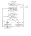
次に、本実施例の作用について図3ないし図6も参照して説明する。先ず、処理の概要について、図3のタイミングチャートを参照しながら説明する。上述のようにアルニコ磁石9bを増減磁する場合は、ロータ3の位置が、アルニコ磁石9bに対して、d軸電流の通電による磁束を効果的に鎖交させることが可能な位置関係になった場合に処理(増減磁シーケンス)を開始する。
Next, the operation of this embodiment will be described with reference to FIGS. First, an outline of the processing will be described with reference to the timing chart of FIG. As described above, when the
通常のモータ制御を行っている期間(0)から増減磁シーケンスを開始すると、最初はd軸電流を増加させる[シーケンス(1),(d)参照](尚、q軸電流Iqは、図3の全期間に亘って一定である)。このとき、着磁制御部61は、上位システム(洗濯機の制御回路部)から受けた指令が増磁であれば増磁指令を、減磁であれば減磁指令を位置推定補正部62及び着磁制御切替え部63に出力する。着磁制御切替え部63は、増磁指令(減磁指令)が与えられると、電流制御部67に増磁(減磁)電圧指令を出力する。すると、(以下、増磁の場合)d軸電流Idは正の電圧指令Vd_refによって制御され[(e)参照]、q軸電流Iqは電流指令Iq_refによって制御される。
When the increase / decrease magnetizing sequence is started from the period (0) in which the normal motor control is performed, the d-axis current is first increased [see sequences (1) and (d)] (note that the q-axis current Iq is shown in FIG. For all periods of time). At this time, the
また、位置推定補正部62は、増磁指令が与えられると、d軸誘起電圧Edを保持させる指令を速度・位置推定部55に出力する。すると、速度・位置推定部55は、d軸誘起電圧Edを、前回の演算結果のまま保持して一定値とし、その値に基づいて速度ω及び角度θを推定する。
そして、d軸電流Idが、着磁制御部61より与えられる増減電流値I1に達すると、次のシーケンス(2)に移行してd軸電流Idを減少させる。このとき、着磁制御切替え部63は、d軸電圧指令Vd_refを負の値(或いはゼロに固定し[(e)参照]、d軸電流Idを急激に減少させる[(d)参照]。
Further, the position estimation correction unit 62 outputs a command for maintaining the d-axis induced voltage Ed to the speed /
When the d-axis current Id reaches the increase / decrease current value I1 given from the
d軸電流Idが減少して所定値I2(>0)以下まで減少すると、次のシーケンス(3)に移行する。この時点で、着磁制御切替え部63は、d軸側を電流指令Id_refによる電流制御に戻すので、d,q軸は何れも電流指令Id_ref,Iq_refに基づく制御となる。さらに時間が経過して、d軸電流Idがゼロになると、着磁制御部61は増磁指令の出力を停止し、通常のモータ制御に戻る[期間(4)]。増磁指令の出力が停止すると、位置推定補正部62は、Ed保持指令の出力を停止して、速度・位置推定部55のEd演算器56によるd軸誘起電圧Edの演算を再開させる。
When the d-axis current Id decreases and decreases to a predetermined value I2 (> 0) or less, the process proceeds to the next sequence (3). At this time, the magnetization control switching unit 63 returns the d-axis side to the current control based on the current command Id_ref, so that both the d and q axes are controlled based on the current commands Id_ref and Iq_ref. When the time elapses and the d-axis current Id becomes zero, the
図4は、着磁制御部61を中心とする着磁制御の内容を示すフローチャートであり、一定周期毎に実行される。着磁制御部61は、上記制御回路部(洗濯機システム)より増減磁指令を受けていない間は、ステップS1からS11に移行して、着磁動作カウンタをゼロクリアする。そして、増減磁指令を受けるとステップS2に移行し、その時点での着磁動作カウンタ値が、増減磁終了時間(例えば、10m秒)に一定時間を加えた時間に相当する値よりも小さいか否かを判断する。
FIG. 4 is a flowchart showing the content of the magnetization control centered on the
ステップS2で、(着磁動作カウンタ)<(増減磁終了時間)+(一定時間)
であれば(YES)着磁動作カウンタをインクリメントして(ステップS3)、位置推定補正指令を出力する(ステップS4)。ここで、(増減磁終了時間)+(一定時間)は、図3におけるシーケンス(1)〜(3)の期間長に対応する。
In step S2, (magnetization operation counter) <(increase / decrease magnetization end time) + (predetermined time)
If so (YES), the magnetizing operation counter is incremented (step S3), and a position estimation correction command is output (step S4). Here, (magnetization / magnetization end time) + (predetermined time) corresponds to the period length of sequences (1) to (3) in FIG.
次のステップS5で(着磁動作カウンタ)<(増減磁終了時間)であり(YES)、制御回路部より受けた指令が増磁指令の場合は(ステップS6:YES)、位置推定補正部62及び着磁制御切替え部63に対して増磁指令と共に増磁電流指令値を出力する(ステップS7,S8)。また、制御回路部より受けた指令が減磁指令の場合は(ステップS6:NO)、減磁指令と共に減磁電流指令値を出力する(ステップS9,S10)。 In the next step S5 (magnetization operation counter) <(magnetization / magnetization end time) (YES), and when the command received from the control circuit unit is a magnetizing command (step S6: YES), the position estimation correction unit 62 And the magnetizing current command value is output to the magnetizing control switching unit 63 together with the magnetizing command (steps S7 and S8). When the command received from the control circuit unit is a demagnetization command (step S6: NO), a demagnetization current command value is output together with the demagnetization command (steps S9 and S10).
図6は、位置推定補正部62を中心とする制御内容を示すフローチャートである。着磁制御部61より位置推定補正指令が与えられている場合は(ステップS31:YES)、補正モードが、速度・位置推定部55において前回値を使用するタイプか否かを判断する(ステップS32)。尚、補正モードについては、予めユーザが設定可能となっており、上記の前回値使用タイプ/前回値不使用タイプに加えて、前回値使用タイプについては、ステップS33で判断されるモード(1〜3)がある。
FIG. 6 is a flowchart showing control contents centered on the position estimation correction unit 62. When a position estimation correction command is given from the magnetization control unit 61 (step S31: YES), it is determined whether or not the correction mode is a type that uses the previous value in the speed / position estimation unit 55 (step S32). ). The correction mode can be set in advance by the user. In addition to the previous value use type / previous value non-use type, the previous value use type is determined in step S33 (
すなわち、前回値使用タイプであれば(ステップS32:YES)、モード(1〜3)の設定に応じてステップS33からS34〜35に移行する。モード(1)は、Ed演算器56より出力されるd軸誘起電圧Ed(演算結果)を「0」にするモードであり(ステップS34)、モード(2)は、d軸誘起電圧Edの前回値を保持して、今回の値に使用するモードである(ステップS35,図3で説明したケース)。また、モード(3)は、比例積分器57より出力される値を「0」にすることで、加算器58の出力結果を前回得られたω(演算結果)に保持するモードである(ステップS36)。したがって、各モードに応じた指令をEd演算器56若しくは比例積分器57に与える。尚、モード(1)は、厳密には前回値を使用しないが、ここではそれに準ずるものとして分類している。
That is, if it is a previous value use type (step S32: YES), it will transfer from step S33 to S34-35 according to the setting of mode (1-3). Mode (1) is a mode in which the d-axis induced voltage Ed (calculation result) output from the
一方、ステップS32において、前回値不使用タイプである場合は(NO)、Ed演算器56が実行する演算式:(2)式を、一時的に(7)式のように変更する(ステップS37)。
Ed=Vd−R・Id−s・Ld・Id+ω・Lq・Iq …(7)
すなわち、右辺第3項の微分項[−s・Ld・Id]を付加して、d軸誘起電圧Edを求めるようにする。この場合、d軸電流Idを例えば正側に急激に変化させる場合、右辺第1項のVdが非常に大きくなるが、右辺第3項の微分項[−s・Ld・Id]が負側に大きくなるため、左辺のd軸誘起電圧Edが急変することはなくなる。
On the other hand, if the previous value non-use type is determined in step S32 (NO), the equation (2) executed by the
Ed = Vd-R.Id-s.Ld.Id + .omega..Lq.Iq (7)
That is, the differential term [-s · Ld · Id] of the third term on the right side is added to obtain the d-axis induced voltage Ed. In this case, for example, when the d-axis current Id is suddenly changed to the positive side, Vd of the first term on the right side becomes very large, but the differential term [−s · Ld · Id] of the third term on the right side becomes negative. Therefore, the d-axis induced voltage Ed on the left side does not change suddenly.
図5は、着磁制御切替え部63を中心とする制御内容を示すフローチャートであり、この処理は、図4の処理に引き続き実行される。先ず、ステップS12でステップS5と同じ判断,又は着磁動作カウンタ=0か否かを判断する。ここで「NO」と判断する場合は、永久磁石モータ1を通常通りに駆動制御しているケースであるから、上述したように、比例積分器70d内部の切替えスイッチ75が加算器74側を選択するように、すなわち、d軸電流指令Id_refに基づき制御を行うようにする(ステップS17)。
FIG. 5 is a flowchart showing the control content centered on the magnetization control switching unit 63, and this process is executed following the process of FIG. First, in step S12, it is determined whether or not the same determination as in step S5 or the magnetization operation counter = 0. If “NO” is determined here, since the
ステップS12で「YES」と判断する場合は、増減磁処理が行われているケースであるから、d軸電流の上昇が開始された後、そのd軸電流又はU,V,W何れかの相電流が、増減磁電流指令値(図3のI1)に達していないか否かを判断する(ステップS13)。前記指令値に達していない場合(YES)、増磁指令であれば(ステップS14:YES)、切替えスイッチ75にd軸電圧指令Vd_ref側を選択させて、アルニコ磁石9bを増磁させるd軸電圧指令を出力する(ステップS15)。また、減磁指令であれば(ステップS14:NO)、アルニコ磁石9bを減磁させるd軸電圧指令を出力する(ステップS16)。すなわち、ステップS15,S16は、図3のシーケンス(1)に対応する処理である。
If “YES” is determined in step S12, this is a case where the magnetic field increasing / decreasing process is performed. Therefore, after the d-axis current starts to rise, the d-axis current or any phase of U, V, and W is started. It is determined whether or not the current has reached the increase / decrease magnetic current command value (I1 in FIG. 3) (step S13). If the command value has not been reached (YES), if it is a magnetizing command (step S14: YES), the d-axis voltage for magnetizing the
一方、ステップS13で「NO」と判断する場合は、図3のシーケンス(2)に移行したケースであり、d軸電流Id又はU,V,W何れかの相電流が、制御切替え電流値(図3のI2)に達していないか否かを判断する(ステップS18)。前記電流値に達していなければ(YES)、増磁指令であれば(ステップS19:YES)、d軸電流Idを減少させるようにd軸電圧指令Vd_refを出力する(ステップS20)。また、減磁指令であれば(ステップS19:NO)、減磁方向のd軸電流Idを減少させるようにd軸電圧指令Vd_refを出力する(ステップS21)。 On the other hand, if “NO” is determined in step S13, this is a case in which the process proceeds to the sequence (2) in FIG. It is determined whether or not I2) in FIG. 3 has not been reached (step S18). If the current value has not been reached (YES), if it is a magnetizing command (step S19: YES), a d-axis voltage command Vd_ref is output so as to decrease the d-axis current Id (step S20). If it is a demagnetization command (step S19: NO), a d-axis voltage command Vd_ref is output so as to decrease the d-axis current Id in the demagnetization direction (step S21).
ステップS18で「NO」と判断する場合は、d軸電流Id等が制御切替え電流値に達して図3のシーケンス(3)に移行したケースである。したがって、着磁制御切替え部63は、比例積分器70d内部の切替えスイッチ75が加算器74側を選択するように、d軸電流指令Id_refに基づき制御を行うように切替えさせる(ステップS22)。
If “NO” is determined in the step S18, the d-axis current Id and the like reach the control switching current value and shift to the sequence (3) in FIG. Therefore, the magnetization control switching unit 63 switches the control based on the d-axis current command Id_ref so that the
以上のように本実施例によれば、モータ制御装置50は、速度・位置推定部55が永久磁石モータ1について成立する電圧方程式に基づいて、ロータ3の回転位置θを推定し、その推定された回転位置θに基づいてd軸電流及びq軸電流を演算することで、永久磁石モータ1をベクトル制御する。そして、位置推定補正部62は、着磁制御部61が、インバータ回路52を介してモータ1の巻線5に通電を行いアルニコ磁石9bを着磁する期間に、電圧方程式により得られる演算結果を一時的に固定値に置換することで、推定されるロータ位置θを補正するようにした。具体的には、位置推定補正部62は、ユーザの選択に応じて、d軸誘起電圧Edを着磁制御が開始される直前に演算された値に保持したり、又はゼロに保持したり、或いは、電圧方程式の演算結果より得られる回転速度ωを、着磁制御が開始される直前に演算された値に保持するようにして、演算結果を一時的に固定値に置換する。
As described above, according to the present embodiment, the
すなわち、電流制御においては、q軸側は電流指令に基づく制御を継続し、d軸側の制御を電流指令に基づく制御と電圧指令直値による制御を切り替えることで、増減磁電流が急激に上昇,下降する場合でも、脱調等することなくモータ1の運転を継続することができ、高速な電流の制御が可能になる。そして、このように位置センサレス方式で増減磁を行うことで、洗濯乾燥機21のように低コストが要求される家電用途においても永久磁石モータ1のような可変磁束モータを適用し、モータ1に要求される回転数・トルクの特性に応じて行う増減磁の効果を大きくすることができ、運転領域の全域にわたって高効率な運転が可能となる。したがって、位置センサレス方式で制御する場合でも、モータ1が脱調すること無しに増減磁通電を行うことができる。
That is, in current control, the q-axis side continues control based on the current command, and the control on the d-axis side is switched between control based on the current command and control based on the voltage command direct value, so that the increase / decrease magnetic current increases rapidly. , Even when it is lowered, it is possible to continue the operation of the
また、位置推定補正部62は、ユーザの選択により、着磁制御部61が着磁制御を行う期間は、d軸電圧方程式に一時的に微分項s・Ld・Idを加えてd軸誘起電圧Edを算出するので、着磁制御を行う期間に突発的に大きな電流が流れた場合でも、位置推定演算に用いられるd軸電圧方程式に、瞬時的な変化に対する追従性が良好な微分項s・Ld・Idを一時的に加えてd軸誘起電圧Edを算出するので、誘起電圧Edの急変を抑制することができる。
In addition, the position estimation correction unit 62 temporarily adds a differential term s · Ld · Id to the d-axis voltage equation during a period in which the
そして、着磁制御切替え部63は、モータ制御装置50が、ベクトル制御のフィードバックループ内にPI制御を組み込んでいる場合、着磁制御部61が着磁制御を行う期間は、ベクトル制御における電流指令Id_refを電流制御部67のd軸側に与える制御と、電流指令Id_refに替えて電圧指令Vd_refをdq/uvw座標変換器71に直接出力する制御とを切り替えるようにした。したがって、着磁制御を行う期間に突発的に大きな電流が流れた場合でも、増減磁電流を遅れ無しに通電することができる。
When the
また、着磁制御切替え部63は、着磁制御部61がd軸電流を増加させる指令を出力する期間は、d軸については前記d軸電流を増加させる極性の電圧指令Vd_refを直接与え、q軸については電流制御指令Iq_refを与えるので、d軸電流の通電量を迅速に上昇させることができる。
The magnetization control switching unit 63 directly gives a voltage command Vd_ref having a polarity for increasing the d-axis current for the d-axis during a period in which the
そして、着磁制御切替え部63は、U,V,W何れかの相電流値,又はd軸電流Idの値が、着磁制御部61により与えられる着磁電流指令値I1に達すると、d軸電流Idを減少させるように電圧指令Vd_refを与え、着磁制御部61がd軸電流Idを減少させる指令を出力する期間は、d軸についてはd軸電流Idを減少させる極性の電圧指令Vd_refを直接与え、q軸については電流制御指令Iq_refを与えるので、d軸電流Idの通電量を迅速に下降させることができる。
また、着磁制御切替え部63は、U,V,W何れかの相電流値(絶対値),又はd軸電流Id(絶対値)が一定の閾値I2未満に減少すると、dq軸共に電流制御指令を与えるように切り替えるので、d軸電流Idがゼロに到達するよりも早いタイミングで電流制御指令に基づく制御に切り替えることにより、d軸電流Idが逆極性側にアンダーシュートすることを防止できる。
Then, when the phase current value of any of U, V, W or the value of the d-axis current Id reaches the magnetization current command value I1 given by the
In addition, when the phase current value (absolute value) of any of U, V, or W or the d-axis current Id (absolute value) decreases below a certain threshold value I2, the magnetization control switching unit 63 controls the current for both the dq axes. Since switching is performed so as to give a command, switching to control based on the current control command at a timing earlier than when the d-axis current Id reaches zero can prevent the d-axis current Id from undershooting to the reverse polarity side.
また、モータ電流を、電流センサ(例えば、カレントトランス)51を用いて検出する場合は問題ないが、上述のようにインバータ回路51の下アーム側にシャント抵抗を挿入して電流を検出する場合は、以下のような問題が生じる。この場合、電流検出は、下アーム側のスイッチング素子がオンしている期間中にシャント抵抗の端子電圧を検出することで行う。すると、着磁制御部61が着磁制御を行う場合は、d軸電流Idを通電する期間が非常に短くなるため、それに伴い、下アーム側スイッチング素子がオンしている時間もPWMデューティが0%に近い状態になることから、電流検出が困難になる。
そして、本実施例によれば、位置推定補正部62の作用により、上記のようなケースにおいても、速度・位置推定部55はモータ電流が検出されない期間に位置推定を行うことが可能となる。したがって、電流センサ51に替えてシャント抵抗を用いることで、製品のコストダウンに寄与することができる。
In addition, there is no problem when the motor current is detected using a current sensor (for example, a current transformer) 51, but when a current is detected by inserting a shunt resistor on the lower arm side of the inverter circuit 51 as described above. The following problems arise. In this case, current detection is performed by detecting the terminal voltage of the shunt resistor during the period when the lower arm side switching element is ON. Then, when the
According to the present embodiment, the speed /
(第2実施例)
図10は第2実施例であり、第1実施例のモータ制御装置50を空調機(エアコンディショナ)に適用した場合を示す。ヒートポンプ101を構成するコンプレッサ(負荷)102は、圧縮部103とモータ104を同一の鉄製密閉容器105内に収容して構成され、モータ104のロータシャフトが圧縮部103に連結されている。そして、コンプレッサ102、四方弁106、室内側熱交換器107、減圧装置108、室外側熱交換器109は、冷媒通路たるパイプにより閉ループを構成するように接続されている。尚、コンプレッサ102は、例えばロータリ型のコンプレッサであり、モータ104は、第1実施例のモータ1と同様に構成される永久磁石モータである。
(Second embodiment)
FIG. 10 is a second embodiment, and shows a case where the
暖房時には、四方弁106は実線で示す状態にあり、コンプレッサ102の圧縮部103で圧縮された高温冷媒は、四方弁106から室内側熱交換器107に供給されて凝縮し、その後、減圧装置108で減圧され、低温となって室外側熱交換器109に流れ、ここで蒸発してコンプレッサ102へと戻る。一方、冷房時には、四方弁106は破線で示す状態に切り替えられる。このため、コンプレッサ102の圧縮部103で圧縮された高温冷媒は、四方弁106から室外側熱交換器109に供給されて凝縮し、その後、減圧装置108で減圧され、低温となって室内側熱交換器107に流れ、ここで蒸発してコンプレッサ102へと戻る。そして、室内側、室外側の各熱交換器107,109には、それぞれファン110,111により送風が行われ、その送風によって各熱交換器107,109と室内空気、室外空気の熱交換が効率良く行われるように構成されている。
During heating, the four-
以上のように構成される第2実施例によれば、永久磁石モータ104とインバータ装置50とで構成されるモータ制御システムを空調機に適用して、コンプレッサ102を駆動するようにしたので、空調機の運転を安定して行うことができると共に、消費電力を低減することができる。
According to the second embodiment configured as described above, the motor control system including the
本発明は上記し又は図面に記載した実施例にのみ限定されるものではなく、以下のような変形又は拡張が可能である。
着磁電流指令値(I1)は、低保持力永久磁石を十分に着磁できる電流値であれば良く、適宜設定が可能である。
また、閾値(I2)は、着磁を行う際に通電するd軸電流Idを減少させる過程において、逆極性側にアンダーシュートが発生することを防止できる値とすれば良く、適宜設定が可能である。
補正モードについては、予め設定した何れか1つのモードだけを実行しても良い。
位置推定を行う際にq軸電圧方程式も用いる場合は、増減磁通電の間、d軸誘起電圧Edだけでなくq軸誘起電圧Eqも同時に保持してもよい。
The present invention is not limited to the embodiments described above or shown in the drawings, and the following modifications or expansions are possible.
The magnetizing current command value (I1) may be a current value that can sufficiently magnetize the low coercive force permanent magnet, and can be set as appropriate.
The threshold value (I2) may be set to a value that can prevent undershoot from occurring on the reverse polarity side in the process of reducing the d-axis current Id that is energized when magnetizing, and can be set as appropriate. is there.
As for the correction mode, only one of the preset modes may be executed.
When the q-axis voltage equation is also used when performing the position estimation, not only the d-axis induced voltage Ed but also the q-axis induced voltage Eq may be simultaneously held during the increase / decrease magnetic energization.
ネオジム磁石9a,アルニコ磁石9bの配置個数比は、個別の設計に応じて適宜変更すれば良い。
低保磁力の永久磁石は、アルニコ磁石に限ることなく、その他例えばサマリウム・コバルト磁石を用いても良い。また、高保磁力の永久磁石もネオジム磁石に限ることはない。
補正については、回転速度を補正せずに、ロータ位置だけを補正しても良い。
洗濯機や空調機に限ることなく、ロータに低保磁力永久磁石が配置される永久磁石モータを制御対象とするものであれば適用が可能である。
The arrangement ratio of the
The low coercive force permanent magnet is not limited to an alnico magnet, but may be another samarium / cobalt magnet, for example. Further, the high coercivity permanent magnet is not limited to the neodymium magnet.
As for the correction, only the rotor position may be corrected without correcting the rotational speed.
The present invention is not limited to a washing machine or an air conditioner, and can be applied as long as a permanent magnet motor in which a low coercive force permanent magnet is arranged on a rotor is a control target.
図面中、1は永久磁石モータ、3はロータ、9aはネオジム磁石、9bはアルニコ磁石(低保磁力永久磁石)、21はドラム式洗濯乾燥機、50はモータ制御装置(ベクトル制御手段)、52はインバータ回路、55は速度・位置推定部(位置推定手段)、61は着磁制御部(着磁制御手段)、62は位置推定補正部(補正手段)、63は着磁制御切替え部(制御指令切替え手段)、77はモータ制御システムを示す。 In the drawings, 1 is a permanent magnet motor, 3 is a rotor, 9a is a neodymium magnet, 9b is an alnico magnet (low coercive force permanent magnet), 21 is a drum-type washer / dryer, 50 is a motor control device (vector control means), 52 Is an inverter circuit, 55 is a speed / position estimation unit (position estimation unit), 61 is a magnetization control unit (magnetization control unit), 62 is a position estimation correction unit (correction unit), and 63 is a magnetization control switching unit (control). (Command switching means) 77 is a motor control system.
Claims (5)
前記永久磁石モータについて成立する電圧方程式に基づいて、前記ロータの回転位置を推定する位置推定手段と、
前記推定された回転位置に基づいてd軸電流及びq軸電流を演算し、前記永久磁石モータを制御するために与えられるd軸電流指令及びq軸電流指令と、前記演算結果との差分をPI制御してd軸電圧指令及びq軸電圧指令を生成出力し、前記永久磁石モータをベクトル制御するベクトル制御手段と、
前記インバータ回路を介して前記モータの巻線に通電を行うことで、前記永久磁石を着磁する着磁制御手段と、
この着磁制御手段が前記永久磁石を着磁するために着磁電流を通電する期間において、前記ベクトル制御における電流指令に基づく制御と、前記電流指令に替えて電圧指令を直接出力する制御とを切り替える制御指令切替え手段とを備えたことを特徴とするモータ制御装置。 Consists of a plurality of semiconductor switching elements connected in multiple phases, between a DC power supply and a winding of a permanent magnet motor in which a plurality of permanent magnets having a low coercive force that can change the amount of magnetization are arranged on the rotor An inverter circuit connected to
Position estimation means for estimating the rotational position of the rotor based on a voltage equation established for the permanent magnet motor;
A d-axis current and a q-axis current are calculated based on the estimated rotational position, and a difference between the d-axis current command and the q-axis current command given to control the permanent magnet motor and the calculation result is PI. A vector control means for controlling and generating and outputting a d-axis voltage command and a q-axis voltage command, and vector-controlling the permanent magnet motor;
Magnetization control means for magnetizing the permanent magnet by energizing the winding of the motor via the inverter circuit;
In the period in which the magnetization control means energizes the magnetizing current to magnetize the permanent magnet, the control based on the current command in the vector control and the control to directly output the voltage command instead of the current command A motor control device comprising control command switching means for switching.
Priority Applications (3)
| Application Number | Priority Date | Filing Date | Title |
|---|---|---|---|
| JP2009217225A JP5127800B2 (en) | 2009-09-18 | 2009-09-18 | Motor control device |
| CN201010274662XA CN102025311B (en) | 2009-09-18 | 2010-09-03 | Motor control device |
| KR1020100086406A KR101189005B1 (en) | 2009-09-18 | 2010-09-03 | Motor control device |
Applications Claiming Priority (1)
| Application Number | Priority Date | Filing Date | Title |
|---|---|---|---|
| JP2009217225A JP5127800B2 (en) | 2009-09-18 | 2009-09-18 | Motor control device |
Publications (2)
| Publication Number | Publication Date |
|---|---|
| JP2011067054A JP2011067054A (en) | 2011-03-31 |
| JP5127800B2 true JP5127800B2 (en) | 2013-01-23 |
Family
ID=43866270
Family Applications (1)
| Application Number | Title | Priority Date | Filing Date |
|---|---|---|---|
| JP2009217225A Active JP5127800B2 (en) | 2009-09-18 | 2009-09-18 | Motor control device |
Country Status (3)
| Country | Link |
|---|---|
| JP (1) | JP5127800B2 (en) |
| KR (1) | KR101189005B1 (en) |
| CN (1) | CN102025311B (en) |
Families Citing this family (12)
| Publication number | Priority date | Publication date | Assignee | Title |
|---|---|---|---|---|
| CN102361430B (en) * | 2011-10-26 | 2013-03-13 | 哈尔滨工业大学 | Position sensor-free vector control device for built-in permanent magnetic synchronous motor |
| CN102403952A (en) * | 2011-11-30 | 2012-04-04 | 徐州中矿大传动与自动化有限公司 | Control device for output voltage estimation method of three-level current transformer |
| CN102545742B (en) * | 2012-02-27 | 2014-03-12 | 固高科技(深圳)有限公司 | Position sensorless control device and control method for permanent magnet synchronous motor |
| KR101382749B1 (en) * | 2012-04-13 | 2014-04-08 | 현대자동차주식회사 | Method for correcting resolver offset |
| KR101688924B1 (en) | 2012-06-21 | 2016-12-22 | 바이오스트림테크놀러지스(주) | Antiobesity effect of hyaluronic acid |
| US9219432B2 (en) * | 2012-07-25 | 2015-12-22 | System General Corporation | Control systems and methods for angle estimation of permanent magnet motors |
| KR101982281B1 (en) | 2012-07-31 | 2019-05-27 | 삼성전자주식회사 | Method and Apparatus for obtaining maximum possible magnetic flux in Permanant Magnet Synchronous Motor |
| CN104143945B (en) * | 2013-05-08 | 2017-08-29 | 上海微电子装备(集团)股份有限公司 | Moving-wire ring magnetic floats the magnetic alignment methods and system of motor |
| CN106549619B (en) * | 2016-10-26 | 2018-11-09 | 东南大学 | A kind of control system for permanent-magnet synchronous motor accurately recognized based on speed |
| KR101912694B1 (en) * | 2017-03-28 | 2018-10-29 | 엘지전자 주식회사 | Module for controlling variable magnetic force motor, apparatus for controlling variable magnetic force motor, system of controlling variable magnetic force motor and mehtod for controlling variable magnetic force motor |
| JP7052255B2 (en) * | 2017-08-25 | 2022-04-12 | コニカミノルタ株式会社 | Image forming device |
| JP7140961B2 (en) * | 2018-03-30 | 2022-09-22 | ダイキン工業株式会社 | motor drive |
Family Cites Families (10)
| Publication number | Priority date | Publication date | Assignee | Title |
|---|---|---|---|---|
| JP2003033097A (en) * | 2001-07-17 | 2003-01-31 | Sanken Electric Co Ltd | Device and method for controlling synchronous motor |
| CN1437314A (en) * | 2002-02-07 | 2003-08-20 | 许俊甫 | Rotation speed raising device for permanent magnetic motor |
| JP4174706B2 (en) * | 2002-04-01 | 2008-11-05 | 株式会社安川電機 | Drive control device for non-salient pole type synchronous motor |
| JP2005304204A (en) * | 2004-04-13 | 2005-10-27 | Mitsubishi Electric Corp | Permanent magnet synchronous motor and drive apparatus |
| KR100757439B1 (en) | 2005-12-30 | 2007-09-11 | 엘지전자 주식회사 | Self-magnetizing motor and his magnetization method |
| JP4965924B2 (en) * | 2006-07-24 | 2012-07-04 | 株式会社東芝 | Variable magnetic flux drive system |
| US8860356B2 (en) * | 2007-09-18 | 2014-10-14 | Kabushiki Kaisha Toshiba | Variable magnetic flux motor drive system |
| JP5329801B2 (en) * | 2007-12-20 | 2013-10-30 | 株式会社東芝 | Variable magnetic flux drive system |
| JP5112219B2 (en) * | 2007-11-05 | 2013-01-09 | 株式会社東芝 | Permanent magnet motor, washing machine and control device |
| JP5226276B2 (en) * | 2007-11-07 | 2013-07-03 | 株式会社東芝 | Washing machine inverter device |
-
2009
- 2009-09-18 JP JP2009217225A patent/JP5127800B2/en active Active
-
2010
- 2010-09-03 KR KR1020100086406A patent/KR101189005B1/en active IP Right Grant
- 2010-09-03 CN CN201010274662XA patent/CN102025311B/en active Active
Also Published As
| Publication number | Publication date |
|---|---|
| CN102025311A (en) | 2011-04-20 |
| CN102025311B (en) | 2013-07-31 |
| KR20110031094A (en) | 2011-03-24 |
| KR101189005B1 (en) | 2012-10-08 |
| JP2011067054A (en) | 2011-03-31 |
Similar Documents
| Publication | Publication Date | Title |
|---|---|---|
| JP5127800B2 (en) | Motor control device | |
| US8129931B2 (en) | Motor control device, motor drive system, washing machine, air conditioner and method of changing magnetization amount of permanent magnet motor | |
| JP4834712B2 (en) | Motor control device, motor control system, washing machine, and method for magnetizing permanent magnet motor | |
| US8327670B2 (en) | Motor controller and drum washing machine | |
| US8174219B2 (en) | Motor control unit and air conditioner having the same | |
| KR101199136B1 (en) | Rotor position detecting device | |
| US8704467B2 (en) | Inverter device for washing machine | |
| JP4314283B2 (en) | Washing and drying machine | |
| US20100148710A1 (en) | Apparatus and method for controlling a bldc motor | |
| JP2003259679A (en) | Vector control inverter apparatus and rotation driving apparatus | |
| JP2009225596A (en) | Driving unit of motor, air conditioner, washing machine, washing dryer, refrigerator, ventilation fan, and heat pump water heater | |
| JP5752546B2 (en) | Motor control device, compressor and heat pump device | |
| JP2011066992A (en) | Motor control apparatus and washing machine | |
| JP4806061B2 (en) | Motor control device | |
| JP2010226914A (en) | Motor control apparatus, drum-type washing machine and method for controlling magnetization of permanent magnet motor | |
| JP2004040861A (en) | Driving-gear of motor | |
| JP2010220400A (en) | Motor control device, motor control system, washing machine, and method for magnetizing permanent-magnet motor | |
| JP3691269B2 (en) | Motor control device | |
| JP2011188668A (en) | Motor controller and washing machine | |
| JP2014187802A (en) | Motor drive device | |
| JP5462222B2 (en) | Rotor position detector | |
| JP2013225979A (en) | Motor driving device, compressor driving device employing the same, and heat exchanger equipped with the same | |
| JP5670077B2 (en) | Motor control device and washing machine | |
| JP2007029327A (en) | Motor driving device of washing and drying machine | |
| JP2008167553A (en) | Control method and controller of synchronous motor |
Legal Events
| Date | Code | Title | Description |
|---|---|---|---|
| A977 | Report on retrieval |
Free format text: JAPANESE INTERMEDIATE CODE: A971007 Effective date: 20110713 |
|
| A131 | Notification of reasons for refusal |
Free format text: JAPANESE INTERMEDIATE CODE: A131 Effective date: 20110726 |
|
| TRDD | Decision of grant or rejection written | ||
| A01 | Written decision to grant a patent or to grant a registration (utility model) |
Free format text: JAPANESE INTERMEDIATE CODE: A01 Effective date: 20121002 |
|
| A01 | Written decision to grant a patent or to grant a registration (utility model) |
Free format text: JAPANESE INTERMEDIATE CODE: A01 |
|
| A61 | First payment of annual fees (during grant procedure) |
Free format text: JAPANESE INTERMEDIATE CODE: A61 Effective date: 20121030 |
|
| R151 | Written notification of patent or utility model registration |
Ref document number: 5127800 Country of ref document: JP Free format text: JAPANESE INTERMEDIATE CODE: R151 |
|
| FPAY | Renewal fee payment (event date is renewal date of database) |
Free format text: PAYMENT UNTIL: 20151109 Year of fee payment: 3 |