JP5116620B2 - Electric motor drive device and refrigeration air conditioner - Google Patents
Electric motor drive device and refrigeration air conditioner Download PDFInfo
- Publication number
- JP5116620B2 JP5116620B2 JP2008233796A JP2008233796A JP5116620B2 JP 5116620 B2 JP5116620 B2 JP 5116620B2 JP 2008233796 A JP2008233796 A JP 2008233796A JP 2008233796 A JP2008233796 A JP 2008233796A JP 5116620 B2 JP5116620 B2 JP 5116620B2
- Authority
- JP
- Japan
- Prior art keywords
- voltage
- axis
- command value
- power consumption
- electric motor
- Prior art date
- Legal status (The legal status is an assumption and is not a legal conclusion. Google has not performed a legal analysis and makes no representation as to the accuracy of the status listed.)
- Active
Links
Images


Landscapes
- Control Of Ac Motors In General (AREA)
Description
本発明は、電動機の駆動装置並びにこの駆動装置を備えた冷凍空調装置に関するものである。 The present invention relates to an electric motor drive device and a refrigeration air conditioner including the drive device.
従来、電動機の駆動装置の電力を求める方法として、『電動機の制御方法において、電圧指令をVref 、d軸成分をvd * 、q軸成分をvq * 、電圧検出値のd軸成分をvd 、q軸成分をvq 、電流検出値のd軸成分をid 、q軸成分をiqとした場合に、内積(vd * ×id +vq * ×iq )あるいは(vd ×id +vq ×iq )を用いてインバータ出力電力Pinv を計算する』というものがある(特許文献1)。
また、『モータ回転角周波数と、トルク指令と、モータ回転子に同期して回転するdq軸直交座標で表わしたd軸電圧およびq軸電圧と、d軸電流およびq軸電流とを入力として、インバータ出力有効電力指令とインバータ出力有効電力とを演算し、かつ当該演算した有効電力が有効電力指令に追従するような電流位相補正値をd軸電流指令およびq軸電流指令演算の補正値として演算して出力する有効電力制御手段を備えて成る』というものもある(特許文献2)。
さらに、『電気車の速度情報および電動機に供給する電流指令ならびに電動機の電流検出値から得たインバータ電圧指令と電動機に供給する電流指令により電動機の消費電力を求める電力演算装置と、フィルタコンデンサ電圧の検出装置と、電力演算装置の求めた電動機の消費電力とフィルタコンデンサ電圧の目標値とフィルタコンデンサ電圧の検出値を用いてフィルタコンデンサ電圧の制御を行う電圧制御装置を有する』というものもある(特許文献3)。
Conventionally, as a method for obtaining electric power of a motor drive device, “in a motor control method, a voltage command is Vref, a d-axis component is vd *, a q-axis component is vq *, and a d-axis component of a voltage detection value is vd, q Inverter output using the inner product (vd ** id + vq ** iq) or (vd * id + vq * iq) where the axis component is vq, the d-axis component of the current detection value is id, and the q-axis component is iq. "Calculate the power Pinv" (Patent Document 1).
In addition, “motor rotation angular frequency, torque command, d-axis voltage and q-axis voltage expressed in dq-axis orthogonal coordinates rotating in synchronization with the motor rotor, and d-axis current and q-axis current are input. The inverter output active power command and the inverter output active power are calculated, and the current phase correction value such that the calculated active power follows the active power command is calculated as a correction value for the d-axis current command and the q-axis current command calculation. In other words, there is an active power control means for outputting the output (Patent Document 2).
Furthermore, “a power calculation device that obtains power consumption of an electric motor based on an inverter voltage command obtained from the speed information of the electric vehicle and an electric current command supplied to the electric motor and an electric current command supplied to the electric motor and an electric current command supplied to the electric motor, and a filter capacitor voltage There is also a detection device and a voltage control device that controls the filter capacitor voltage by using the electric power consumption of the electric motor, the target value of the filter capacitor voltage, and the detected value of the filter capacitor voltage obtained by the power calculation device (patent) Reference 3).
また、下記特許文献4では、センサレス制御に関する技術が開示されている。
上記特許文献1に開示されている電力の計算方法を用いた場合、電圧検出値vd及びvqを用いた場合には精度良く電力を計算可能であるが、電圧を検出するための回路が別途必要となり、コストが高くなり実用的でない。また、vd、vqの代わりにvd*、vq*を用いた場合、インバータに供給されている直流電圧値に対する、電圧指令値の割合である変調率が1を超えるような過変調領域において、電圧指令値と実際に出力される電圧に大きな誤差が生じ正確な電力を計算することができなくなる。
また、上記特許文献2に開示されている従来技術においても、上記特許文献1と同様に過変調領域において、正確な電力を求めることができず、精度良く有効電力制御ができないという課題がある。
さらに、上記特許文献3に開示されている従来技術においても、上記特許文献1及び上記特許文献2と同様に過変調領域において求めた消費電力に誤差が生じ精度良く電圧制御ができないという課題がある。
さらに、上記特許文献4に開示されている従来技術では、過変調領域の運転が可能であるが、この過変調領域において電圧指令値と電動機に印加される電圧が一致せず、電圧指令値と電流から消費電力を正確に推定することが困難であるという課題がある。
When the power calculation method disclosed in
Further, the conventional technique disclosed in
Further, the prior art disclosed in
Further, in the conventional technique disclosed in
本発明は、上記のような課題を解決するためになされたものであり、第1の目的は電動機が過変調領域で動作していた場合においても、精度良く電動機の駆動装置の消費電力を演算することが可能な駆動装置並びに冷凍空調装置を得ることにあり、第2の目的は省エネルギー化を実現しCO2排出量も削減し、また、機器の発熱による経年劣化を抑制可能な信頼性の高い電動機の駆動装置並びに冷凍空調装置を得ることにある。 The present invention has been made to solve the above-described problems, and a first object is to accurately calculate the power consumption of the motor drive device even when the motor is operating in the overmodulation region. The second purpose is to achieve energy savings, reduce CO 2 emissions, and reduce the aging caused by the heat generated by the equipment. The object is to obtain a high electric motor drive device and a refrigeration air conditioner.
本発明に係る電動機の駆動装置は、直流電圧を交流電圧に変換して電動機に印加するインバータと、前記電動機に流れる相電流を検出する電流検出手段と、前記インバータに印加される直流電圧を検出する直流電圧検出手段と、前記インバータが電動機に印加する電圧を制御する制御手段と、位相誤差記憶手段と、を備え、前記制御手段は、前記電流検出手段が検出した相電流を直交2軸座標上の電流としてd軸電流Id及びq軸電流Iqに変換する座標変換手段と、前記座標変換手段の出力と所定の基準値に基づき、前記電動機に印加する前記直交2軸座標上の電圧の指令値としてd軸電圧指令値Vd*及びq軸電圧指令値Vq*を出力する電圧指令値演算手段と、前記直交2軸座標上の電圧指令値であるd軸電圧指令値Vd*及びq軸電圧指令値Vq*と、前記直流電圧とにより変調率を求める変調率演算手段と、前記変調率演算手段の出力である前記変調率とその前記変調率に対する出力電圧の割合である電圧利用率を予め求めておき、前記変調率と前記電圧利用率との対応関係を記憶させ、前記電圧利用率を求めるときには、予め記憶させた前記対応関係に基づいて前記変調率から前記電圧利用率を求める電圧利用率演算手段と、前記直交2軸座標上の電圧指令値であるd軸電圧指令値Vd*及びq軸電圧指令値Vq*と前記直交2軸座標上の電流であるd軸電流Id及びq軸電流Iqとの内積を求め、その求めた内積に対して、前記電圧利用率を乗算すると共に前記変調率を除算することにより、前記電動機の消費電力を求める消費電力演算手段と、を備え、前記位相誤差記憶手段は、前記電動機に印加される電圧と前記電圧の指令値との位相誤差と、前記制御手段が有する変調率演算手段または前記制御手段が有する変調率補正手段の出力との関係を予め記憶し、前記消費電力演算手段は、前記電動機の消費電力を求める際に前記位相誤差記憶手段に記憶された位相誤差に基づいて前記電圧指令値演算手段の出力を補正するものである。 An electric motor driving apparatus according to the present invention includes an inverter that converts a DC voltage into an AC voltage and applies the AC voltage to the motor, current detection means that detects a phase current flowing through the motor, and a DC voltage applied to the inverter. a DC voltage detecting means for a control unit included in the inverter to control the voltage applied to the motor, and a position phase error memory unit, before Symbol control means, said current detecting means quadrature phase current detected is 2 Coordinate conversion means for converting d-axis current Id and q-axis current Iq as currents on the axis coordinates, and voltage on the orthogonal two-axis coordinates applied to the motor based on the output of the coordinate conversion means and a predetermined reference value Voltage command value calculation means for outputting a d-axis voltage command value Vd * and a q-axis voltage command value Vq * as command values for the d-axis, and d-axis voltage command values Vd * and q which are voltage command values on the orthogonal two-axis coordinates Shaft electric A command value Vq *, the modulation factor calculating means for obtaining a modulation rate by said DC voltage, the voltage utilization rate is a percentage of the output voltage to the modulation factor and its the modulation rate which is the output of the modulation factor computation means previously Obtaining and storing the correspondence relationship between the modulation factor and the voltage utilization factor, and obtaining the voltage utilization factor, the voltage utilization for obtaining the voltage utilization factor from the modulation factor based on the correspondence relationship stored in advance Rate calculation means, d-axis voltage command value Vd * and q-axis voltage command value Vq * which are voltage command values on the orthogonal two-axis coordinates, and d-axis current Id and q-axis which are currents on the orthogonal two-axis coordinates obtains an inner product between current Iq, for the calculated inner product, by dividing the modulation factor as well as multiplying the voltage utilization rate, and a power consumption calculating means for calculating the power consumption of the electric motor, wherein Phase error The storage means stores in advance the relationship between the phase error between the voltage applied to the motor and the command value of the voltage, and the output of the modulation factor calculation means included in the control means or the modulation factor correction means included in the control means. The power consumption calculation means corrects the output of the voltage command value calculation means based on the phase error stored in the phase error storage means when determining the power consumption of the motor.
本発明に係る電動機の駆動装置によれば、インバータに供給されている直流電圧値に対する、電圧指令値の割合である変調率が1を超えるような過変調領域においても、精度良く消費電力を演算することが可能となる。 According to the motor drive device of the present invention, power consumption can be calculated accurately even in an overmodulation region where the modulation factor, which is the ratio of the voltage command value to the DC voltage value supplied to the inverter, exceeds 1. It becomes possible to do.
実施の形態1.
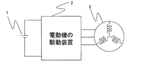
図1は、本発明の実施の形態1に係る電動機の駆動装置の構成を示す図である。
図1において、1は直流電源、2は本実施の形態1に係る電動機の駆動装置、3は電動機である。
FIG. 1 is a diagram showing a configuration of an electric motor drive device according to
In FIG. 1, 1 is a DC power source, 2 is a motor drive device according to the first embodiment, and 3 is an electric motor.
図2は、電動機3の解析モデル図である。図2には、U相、V相、W相の電機子巻線固定軸が示されている。4は、電動機3の回転子を構成する永久磁石である。永久磁石4が作る磁束と同じ速度で回転する回転座標系において、永久磁石4が作る磁束の方向をd軸にとり、d軸に対応する制御上の推定軸をγ軸とする。また、図示していないが、d軸から電気角で90度進んだ位相にq軸をとり、γ軸から電気角で90度進んだ位相に推定軸であるδ軸をとる。d軸とq軸を座標軸に選んだ回転座標系の座標軸をdq軸と呼ぶ。インバータによる制御上の回転座標系はγ軸とδ軸を座標軸に選んだ座標系であり、その座標軸をγδ軸と呼ぶ。
FIG. 2 is an analysis model diagram of the
dq軸は回転しており、その回転速度である電動機3の回転速度を電動機回転速度ω と呼ぶ。γδ軸も回転しており、その回転速度をインバータ回転速度ω1と呼ぶ。また、ある瞬間の回転しているdq軸において、d軸の位相をU相の電機子巻線固定軸を基準として電動機回転位相θにより表す。同様に、ある瞬間の回転しているγδ軸において、γ軸の位相をU相の電機子巻線固定軸を基準としてインバータ回転位相θ1により表す。そうすると、d軸とγ軸との軸誤差Δθは、Δθ=θ−θ1 で表される。
The dq axis is rotating, and the rotation speed of the
γδ軸はdq軸を推定しており、実際の運転では軸誤差Δθが小さい所で運転されることもあり、dq軸とγδ軸は同一と捉えることが可能である。そのため、以下特別なことが無い限り、dq軸として説明を行うが、γδ軸においても同様の構成で実現できることは言うまでもない。 As the γδ axis, the dq axis is estimated. In actual operation, the axis may be operated where the axis error Δθ is small, and the dq axis and the γδ axis can be regarded as the same. For this reason, the following description will be made assuming that the dq axis is used unless otherwise specified. Needless to say, the γδ axis can be realized with the same configuration.
電動機の駆動装置2は、インバータ主回路5、電流検出手段6、直流電圧検出手段7、インバータ制御手段8を有する。
The electric
インバータ主回路5は、IGBTやMOSFET等のスイッチング素子を有し、各スイッチング素子には並列に接続された環流ダイオードを備える。
The inverter
電流検出手段6は電動機3に流入するU相電流、V相電流、W相電流をそれぞれ検出し、インバータ制御手段8へ出力する。
直流電圧検出手段7は、インバータ主回路5に印加される直流電源1の電圧を検出し、インバータ制御手段8に出力する。
インバータ制御手段8は、電流検出手段6、直流電圧手段7の出力に基づいて駆動信号を出力し、インバータ主回路5内のスイッチング素子のオン・オフを制御する。
The current detection means 6 detects U-phase current, V-phase current, and W-phase current flowing into the
The DC voltage detection means 7 detects the voltage of the
The inverter control means 8 outputs a drive signal based on the outputs of the current detection means 6 and the DC voltage means 7 and controls on / off of the switching elements in the inverter
インバータ制御手段8は、電流検出手段6の出力Iu、Iv、Iw、直流電圧検出手段7の出力Vdc、外部から入力した回転数指令ω*及びd軸電流指令Id*に基づいてインバータ主回路5のスイッチング素子をオン・オフするための駆動信号を出力するものであり、座標変換手段9、電圧利用率演算手段10、消費電力演算手段11、印加電圧制御手段12を有する。
The inverter control means 8 is connected to the inverter
座標変換手段9は、電流検出手段6により出力された電流(Iu、Iv、Iw)を、印加電圧制御手段12より得られた電動機回転位相θを用いて、d軸電流Idおよびq軸電流Iqに変換して出力する。 The coordinate conversion means 9 uses the electric motor rotation phase θ obtained from the applied voltage control means 12 to convert the currents (Iu, Iv, Iw) output from the current detection means 6 into the d-axis current Id and the q-axis current Iq. Convert to and output.
電圧利用率演算手段10は、印加電圧制御手段12から得られた変調率Vkに基づいて、電圧利用率Kvを出力する。 The voltage utilization rate calculating means 10 outputs a voltage utilization rate Kv based on the modulation rate Vk obtained from the applied voltage control means 12.
消費電力演算手段11は、座標変換手段9からの出力(Id、Iq)と、印加電圧制御手段12から出力されたdq軸電圧指令値Vd*、Vq*、変調率Vk及び電圧利用率演算手段から出力された電圧利用率Kvに基づいて、電動機の駆動装置の消費電力Pを演算により求める。消費電力Pの演算方法については後述する。 The power consumption calculation means 11 includes outputs (Id, Iq) from the coordinate conversion means 9, dq axis voltage command values Vd * and Vq * output from the applied voltage control means 12, modulation rate Vk, and voltage utilization rate calculation means. Based on the voltage utilization rate Kv output from the motor, the power consumption P of the motor drive device is obtained by calculation. A method for calculating the power consumption P will be described later.
印加電圧制御手段12は、速度補償手段13および、積分手段14、電圧指令演算手段15、変調率・位相指令演算手段16、駆動信号生成手段17を有する。
The applied
速度補償手段13は座標変換手段9より出力されたq軸電流Iqに基づいて、回転数指令ω*を次式(1)により速度補償し、インバータ回転数指令ω1を出力する。 Based on the q-axis current Iq output from the coordinate conversion means 9, the speed compensation means 13 compensates the speed of the rotational speed command ω * by the following equation (1) and outputs an inverter rotational speed command ω1.

積分手段14は速度補償手段13から出力されたω1を積分し、電動機回転位相θを出力する。 The integrating means 14 integrates ω1 output from the speed compensating means 13 and outputs the motor rotation phase θ.
電圧指令演算手段15はインバータ回転数指令ω1及びd軸電流指令値Id*、dq軸の検知電流Id、Iqに基づいて、dq軸の電圧指令値Vd*、Vq*を出力する。
なお、上記の例では回転数指令ω*、およびd軸電流指令値Id*に基づいて電圧指令値Vd*、Vq*を出力したが、巻線抵抗、巻線インダクタンス、誘起電圧定数等のモータパラメータやトルク指令に基づいて電圧指令値Vd*、Vq*を出力してもよい。
The voltage command calculation means 15 outputs the dq axis voltage command values Vd * and Vq * based on the inverter rotation speed command ω1, the d axis current command value Id *, and the dq axis detection currents Id and Iq.
In the above example, the voltage command values Vd * and Vq * are output based on the rotation speed command ω * and the d-axis current command value Id *. However, the motors such as winding resistance, winding inductance, induced voltage constant, etc. Voltage command values Vd * and Vq * may be output based on parameters and torque commands.
変調率・位相指令演算手段16は、直流電圧検出手段7の出力である直流電圧Vdc、およびdq軸電圧指令Vd*、Vq*、電動機回転位相θに基づいて、変調率Vkおよび位相指令θ*を出力する。変調率Vkの演算式については後述する。位相指令θ*については次式(2)に基づいて算出する。 The modulation factor / phase command calculation means 16 is based on the DC voltage Vdc output from the DC voltage detection means 7, the dq axis voltage commands Vd * and Vq *, and the motor rotation phase θ, and the modulation rate Vk and phase command θ *. Is output. An equation for calculating the modulation factor Vk will be described later. The phase command θ * is calculated based on the following equation (2).
駆動信号生成手段17は、変調率・位相指令演算手段16の出力である、変調率Vkおよび位相指令θ*に基づいて、駆動信号を出力し、インバータ主回路5を動作させて、電動機3を駆動する。
The drive
ここで、消費電力演算手段11における消費電力演算方法の一例について説明する。
電動機3の消費電力つまり有効電力は一般に電動機3に印加される電圧の実効値|V|と、流れる電流の実効値|I|と電圧と電流の位相差φを用いて式(3)で表される。
Here, an example of the power consumption calculation method in the power consumption calculation means 11 will be described.
The power consumption, that is, the effective power of the
![]()
![]()
ここで、電圧および電流のベクトルが図4に示すdq座標上に存在したと仮定し、d軸と電圧とがなす角をθv、d軸と電流とがなす角をθiとすると、式(3)は次式(4)にて表すことが可能となる。 Here, assuming that the voltage and current vectors exist on the dq coordinate shown in FIG. 4, assuming that the angle between the d axis and the voltage is θv, and the angle between the d axis and the current is θi, the equation (3 ) Can be expressed by the following equation (4).
式(4)から明らかなように、電動機3の消費電力Pはdq軸の電圧と電流の内積にて求めることが可能となる。つまり、先に説明したγδ軸上の電圧Vγ、Vδおよび電流Iγ、Iδを用いて同様に消費電力を求めた場合においても、消費電力演算手段11は内積により消費電力Pを求めており、この内積には軸誤差Φが介在しないため、軸誤差による影響を受けることはないため、γδ軸上でも何ら問題はないことは言うまでもない。
As is apparent from the equation (4), the power consumption P of the
しかしながら、図5に示すように過変調領域においては、電圧ベクトルが出力電圧の制限値を超過しており、実際に出力される電圧は飽和する。従って、変調率Vkの値は次式(5)から明らかなように1より大きい値となる。 However, as shown in FIG. 5, in the overmodulation region, the voltage vector exceeds the limit value of the output voltage, and the actually output voltage is saturated. Therefore, the value of the modulation factor Vk is larger than 1 as is apparent from the following equation (5).
つまり、過変調領域において従来技術の通り、電圧指令Vd*およびVq*を用いて電力を求めた場合、実際の消費電力と、消費電力演算値は一致しなくなるという問題が発生する。 That is, when power is obtained using voltage commands Vd * and Vq * as in the prior art in the overmodulation region, there is a problem that the actual power consumption does not match the power consumption calculation value.
そこで、消費電力演算手段11は次式(6a)および式(6b)を用いて変調率1相当の電圧指令Vd1、Vq1に変換を行う。
Therefore, the power consumption calculating means 11 converts the voltage commands Vd1 and Vq1 corresponding to the
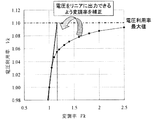
ただし、実際には変調率1を超えても図5中の出力電圧制限値内までは電圧を出力することが可能となる。そこで、電圧利用率演算手段10は変調率1を超えた領域においては、変調率Vkに対する出力電圧の割合である電圧利用率Kvの関係を図6に示すように予め求めて記憶しておき、消費電力演算手段11は式(7a)および式(7b)に示すように電圧利用率演算手段10から出力されたKvを式(6a)および式(6b)に乗ずることで、実際に出力される電圧Vd_realおよびVq_realを求めることが可能となる。 However, actually, even if the modulation factor exceeds 1, the voltage can be output up to the output voltage limit value in FIG. Therefore, in the region where the modulation factor exceeds 1, the voltage utilization factor calculation means 10 obtains and stores in advance the relationship of the voltage utilization factor Kv, which is the ratio of the output voltage to the modulation factor Vk, as shown in FIG. The power consumption calculation means 11 is actually output by multiplying the expression (6a) and the expression (6b) by Kv output from the voltage utilization rate calculation means 10 as shown in the expressions (7a) and (7b). The voltages Vd_real and Vq_real can be obtained.
そして、消費電力演算手段11は式(4)のVdおよびVqに代えて、式(7a)および式(7b)のVd_real、Vq_realを用いることで次式(8)に示す消費電力を得ることができる。 The power consumption calculating means 11 can obtain the power consumption shown in the following equation (8) by using Vd_real and Vq_real in equations (7a) and (7b) instead of Vd and Vq in equation (4). it can.
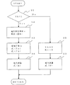
図7に本発明の消費電力を求めるためのフローチャートを示す。次に消費電力算出の動作を図7を参照して説明する。消費電力演算手段11は、変調率Vkが1以下(ステップS1でNo)の場合には、消費電力演算手段11は変調率Vkおよび電圧利用率Kvを1として(ステップS2)、式(8)によって電力を求める(ステップS3)。また、変調率Vkが1を超える過変調領域(ステップS1でYes)においては、消費電力演算手段11は図6の関係に基づき電圧利用率Kvを求め(ステップS4)、式(7a)(7b)によって実電圧を求め(ステップS5)、次に式(8)によって消費電力を求める(ステップS6)。これにより、消費電力を精度良く求めることが可能となる。
FIG. 7 shows a flowchart for obtaining the power consumption of the present invention. Next, the power consumption calculation operation will be described with reference to FIG. When the modulation rate Vk is 1 or less (No in step S1), the power
従って、インバータ制御手段8は、例えば、消費電力演算手段11によって求めた消費電力Pをインバータ制御手段8の外部に設けた液晶等の表示デバイスに表示させてユーザに消費電力Pを知らせ、この消費電力Pが一定の値に達した場合にブザー等の報知手段にその旨の報知情報を出力して報知することで、エネルギーの無駄遣いを知らせることができ、省エネルギーを図ることが可能となる。 Therefore, for example, the inverter control means 8 displays the power consumption P obtained by the power consumption calculation means 11 on a display device such as a liquid crystal provided outside the inverter control means 8 to inform the user of the power consumption P, and this consumption When the electric power P reaches a certain value, the notification information such as a buzzer is output and notified, so that it is possible to notify the waste of energy and to save energy.
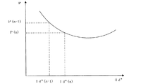
また、インバータ制御手段8は、図3中のd軸電流指令値を、求めた消費電力Pが最小となるように制御することで、省エネルギー性能を高めることができるため、CO2排出量も削減でき、地球温暖化対策が可能な電動機の駆動装置を提供することが可能となる。例えば、図8に示すような消費電力を電動機3の運転中は所定の周期で周期的に次式(9)で示される傾きdを求め、傾きdが負のときはd軸電流指令値Id*を増やし、傾きが正になったらd軸電流指令値Id*を減らすようにする。このような操作を周期的に繰り返すことにより、消費電力Pの最小値を容易に求めることができる。
Further, the inverter control means 8 can improve the energy saving performance by controlling the d-axis current command value in FIG. 3 so that the obtained power consumption P is minimized, so that the CO 2 emission amount is also reduced. It is possible to provide a motor drive device capable of taking measures against global warming. For example, the power consumption as shown in FIG. 8 is obtained periodically during the operation of the
また、消費電力が最小となることにより、発熱等も抑えられるため、熱による経年劣化も少なく、信頼性の高い電動機の駆動装置を提供できるだけでなく、放熱板等も小型化可能となり、低コスト化も図れる。
In addition, since heat generation is suppressed by minimizing power consumption, it is possible not only to provide a highly reliable motor drive device with little deterioration over time due to heat, but also to reduce the size of the heat sink, etc. Can also be achieved.
さらに、インバータ制御手段8は、予め消費電力Pの上限値を記憶しておき、その消費電力の上限値を超えないような最大の回転数で電動機を駆動する。これにより、電動機3は最大限の能力を発揮することが可能となり、例えば冷凍空調装置に適用した場合、冷房や暖房能力を大きく向上させることが可能となる。また、消費電力Pの上限値を低めに設定することにより、消費電力Pを抑えることが可能となり、省エネルギー性の高い電動機の駆動装置を提供することが可能となる。
Furthermore, the inverter control means 8 stores the upper limit value of the power consumption P in advance, and drives the motor at the maximum number of revolutions that does not exceed the upper limit value of the power consumption. Thereby, the
また、消費電力演算手段11の出力の変化に基づいて、電動機3の脱調状態を検出する脱調検出手段(図示せず)を設けてもよい。これにより、電動機3にかかる負荷が急変し、電動機3が脱調状態に陥った場合でも、インバータ制御手段8は脱調検出手段の出力に基づいて電動機3の脱調状態を検出することができ、この電動機3を再起動することで、早急な復帰が可能となり、信頼性および顧客満足度の高い電動機の駆動装置を提供することが可能となる。
Further, step-out detection means (not shown) for detecting the step-out state of the
なお、インバータ制御手段8は、消費電力演算手段11の出力に基づいて料金計算を行い、外部に設けられた表示装置に表示して課金サービスの支援を行うことも可能である。 The inverter control means 8 can also calculate the fee based on the output of the power consumption calculation means 11 and display it on a display device provided outside to support the charging service.
実施の形態2.
実施の形態1では、過変調領域において精度良く消費電力を求める方法について説明した。
本発明の実施の形態2では、出力電圧が飽和する過変調領域において電圧指令と出力電圧が1対1で出力されるように変調率Vkを補正した場合に、精度良く消費電力を求める方法について説明する。
In the first embodiment, the method for accurately obtaining the power consumption in the overmodulation region has been described.
図9は、本発明の実施の形態2に係る電動機の駆動装置の構成を示す図である。
実施の形態2は、変調率補正手段18を備える以外は実施の形態1と何ら変わりはないため、実施の形態1と同じ符号を付して説明を省略する。
FIG. 9 is a diagram showing the configuration of the electric motor drive device according to
Since the second embodiment is the same as the first embodiment except that it includes the modulation rate correction means 18, the same reference numerals as those in the first embodiment are given and the description thereof is omitted.
まず、変調率補正手段18について説明する。変調率補正手段18は変調率・位相指令演算手段16の出力である変調率Vkを入力として、補正変調率Vk'を出力し、駆動信号生成手段17を動作させる。 First, the modulation rate correction means 18 will be described. The modulation rate correction means 18 receives the modulation rate Vk output from the modulation rate / phase command calculation means 16, outputs the correction modulation rate Vk ′, and operates the drive signal generation means 17.
変調率補正手段18は、図10に示すように、変調率Vkが1以下の領域においては、変調率Vkと電圧利用率Kvの関係が線形になっており、電圧指令値に対して出力電圧値は一致する。しかしながら、変調率Vkが1を超える過変調領域においては出力電圧が飽和し、非線形な特性となる。そこで、図11に示すように変調率Vkに対して電圧利用率Kvが線形特性となるように、図12に示すように変調率Vkに対して補正変調率Vk'を用いる。なお、変調率補正手段18は、過変調領域においてはこの補正変調率Vk'を変調率Vkに対する電圧利用率Kvの関数の逆関数により算出してもよい。 As shown in FIG. 10, the modulation factor correction means 18 has a linear relationship between the modulation factor Vk and the voltage utilization factor Kv in the region where the modulation factor Vk is 1 or less. The values match. However, in the overmodulation region where the modulation factor Vk exceeds 1, the output voltage is saturated and becomes a non-linear characteristic. Therefore, as shown in FIG. 11, the correction modulation rate Vk ′ is used for the modulation rate Vk as shown in FIG. 12 so that the voltage utilization rate Kv has a linear characteristic with respect to the modulation rate Vk. Note that the modulation factor correction means 18 may calculate the correction modulation factor Vk ′ in the overmodulation region by an inverse function of a function of the voltage utilization factor Kv with respect to the modulation factor Vk.
しかし、この方法を用いた場合、出力電圧を増加させて効果的に電圧を利用できる反面、実施の形態1の方法では精度良く消費電力を求めることができないという課題がある。 However, when this method is used, the voltage can be effectively used by increasing the output voltage, but the method of the first embodiment has a problem that the power consumption cannot be obtained with high accuracy.
そこで、電圧利用率演算手段10は変調率補正手段18の出力である補正変調率Vk'をもとに電圧利用率Kvを求める。次に、求めた電圧利用率Kvと、変調率Vk、dq軸電圧および電流を用いて消費電力演算手段11にて精度良く消費電力Pを求めることが可能となる。 Therefore, the voltage utilization rate calculation means 10 obtains the voltage utilization rate Kv based on the corrected modulation rate Vk ′ that is the output of the modulation rate correction means 18. Next, the power consumption calculating means 11 can accurately determine the power consumption P using the obtained voltage utilization rate Kv, the modulation rate Vk, the dq axis voltage, and the current.
よって、出力電圧増加による電動機の能力向上及び、精度良く消費電力を演算可能となるため、演算により求めた消費電力に基づいて消費電力が最小となるよう実施の形態1と同様の方法でd軸電流指令値Id*を制御することにより、省エネルギーかつ高性能な電動機の駆動装置を提供可能である。 Therefore, since the capacity of the motor can be improved by increasing the output voltage and the power consumption can be calculated with high accuracy, the d-axis is obtained in the same manner as in the first embodiment so that the power consumption is minimized based on the power consumption obtained by the calculation. By controlling the current command value Id *, an energy-saving and high-performance motor drive device can be provided.
実施の形態3.
実施の形態1および実施の形態2ではデッドタイムによる影響が無い場合の、消費電力の演算方法について説明した。
実施の形態3においては、インバータ主回路を駆動する際に、上下スイッチング素子の短絡防止のために用いる短絡防止時間(デッドタイム)による影響を低減させる方法について説明する。
In the first embodiment and the second embodiment, the calculation method of power consumption when there is no influence by the dead time has been described.
In the third embodiment, a method for reducing the influence of the short-circuit prevention time (dead time) used for preventing the short circuit of the upper and lower switching elements when the inverter main circuit is driven will be described.
図13はインバータ主回路5の一例である。インバータ主回路5はここでは6つのスイッチング素子19aから19fと、6つの環流ダイオード20aから20fで構成される。例えば19aをオフさせた瞬間に、19dをオンさせると、同時にオンする時間が発生する可能性があり、インバータ主回路5が破壊に至ることがある。そこで、図13中に示すようにデッドタイムを設けて同時オンを抑制することで、インバータの破壊を防止する方法が一般的に用いられる。しかし、デッドタイムにより駆動信号が削られることにより、本来出力すべき電圧が出力できない問題があり、電圧指令と実際の出力電圧値が一致しない課題がある。そのため、前述の消費電力計算式にて例えばd軸及びq軸の電圧指令値Vd*およびVq*を用いた場合、正確な消費電力が求まらない恐れがある。
FIG. 13 is an example of the inverter
図14は、本発明の実施の形態3に係る電動機の駆動装置の構成を示す図である。
実施の形態3は、デッドタイム補正手段21を備える以外は実施の形態1と何ら変わりはないため、実施の形態1と同じ符号を付して説明を省略する。
FIG. 14 is a diagram showing the configuration of the electric motor drive device according to
Since the third embodiment is the same as the first embodiment except that the dead
デッドタイム補正手段21はU相、V相、W相の電流Iu、Iv、Iwに基づいてデッドタイム補正量ΔVu、ΔVv、ΔVwを生成して、駆動信号生成手段17に出力することで、デッドタイムにより発生する電圧誤差を補正することで、電圧指令と実際の出力電圧値を一致させることが可能となり、消費電力の計算誤差を低減させることが可能となる。 The dead time correction means 21 generates dead time correction amounts ΔVu, ΔVv, ΔVw based on the U phase, V phase, and W phase currents Iu, Iv, Iw, and outputs the dead time correction amounts to the drive signal generation means 17. By correcting the voltage error caused by the time, the voltage command and the actual output voltage value can be matched, and the power consumption calculation error can be reduced.
図15は一般的なデッドタイム補正の方法を示している。例えばU相のデッドタイム補正量ΔVuはU相電流Iuの極性を用いて次式(10)で得られる。 FIG. 15 shows a general dead time correction method. For example, the U-phase dead time correction amount ΔVu is obtained by the following equation (10) using the polarity of the U-phase current Iu.
![]()
![]()
また、インバータ制御手段8より出力される駆動信号をデッドタイム補正する方法以外に、図16に示すようにdq軸の電圧指令Vd*、Vq*に、電圧誤差推定手段22を用いて、デッドタイムにより発生する電圧誤差を考慮することで、実電圧dq軸の実電圧Vd_realおよびVq_realを推定して、電動機の消費電力を精度良く計算する方法について説明する。Vd_realおよびVq_realはdq軸の電圧誤差ΔVdおよびΔVqを用いて表すと次式(14)となる。 In addition to the method of correcting the dead time of the drive signal output from the inverter control means 8, the dead time is determined by using the voltage error estimating means 22 for the voltage commands Vd * and Vq * on the dq axis as shown in FIG. A method for accurately calculating the power consumption of the motor by estimating the actual voltages Vd_real and Vq_real of the actual voltage dq axis by considering the voltage error generated by the above will be described. Vd_real and Vq_real are expressed by the following equation (14) using voltage errors ΔVd and ΔVq of the dq axis.
次にVd_realおよびVq_realの求め方について説明する。図15によれば、デッドタイムによる電圧誤差分をデッドタイム補正量を用いて、駆動信号生成手段にて駆動信号を補正することで、電圧指令と実際の出力電圧値を一致させることが可能である。つまり、デッドタイム補正量は言い換えれば、デッドタイムにより発生した電圧誤差と見なすことができる。式(10)、(12)、(13)はUVW相の値であるため、式(15)に示すように、直交固定子座標のαβ軸の値ΔVα、ΔVβに変換を行う。 Next, how to obtain Vd_real and Vq_real will be described. According to FIG. 15, it is possible to match the voltage command with the actual output voltage value by correcting the drive signal by the drive signal generation means using the dead time correction amount for the voltage error due to the dead time. is there. In other words, the dead time correction amount can be regarded as a voltage error caused by the dead time. Since the equations (10), (12), and (13) are the values of the UVW phase, as shown in the equation (15), the values are converted into the αβ axis values ΔVα and ΔVβ of the orthogonal stator coordinates.
ただし、この方法を用いた場合に前述のデッドタイム補正を行うと、重複してデッドタイムの補正を行うことになるので、どちらか一方のみを用いる必要があることは言うまでもない。 However, if the above-described dead time correction is performed when this method is used, it is needless to say that only one of them needs to be used because the dead time is corrected.
実施の形態4.
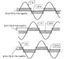
インバータ制御手段8は、通常マイコン等の演算装置にて、ある制御周期毎に電流を検出した後、電圧指令値を演算し、算出された電圧指令値を電圧として電動機に印加する離散的な制御を実施している関係上、図17に示すように電圧指令と実際の出力電圧の位相に誤差(遅れ)が生じる。また、変調率Vkが1を超える過変調領域においては、出力電圧が制限されるため、図18に示すように出力電圧が、台形状となり変調率が無限大となると矩形波状となる。そのため、電圧指令に高調波成分が重畳し、同様に電圧指令と実際の出力電圧の位相に誤差が生じる。
実施の形態4においては、電圧指令と出力電圧の位相に誤差が生じた場合の、補正方法について説明する。
The inverter control means 8 is a discrete control in which an arithmetic unit such as a microcomputer detects a current every certain control cycle, calculates a voltage command value, and applies the calculated voltage command value as a voltage to the motor. Therefore, as shown in FIG. 17, an error (delay) occurs in the phase between the voltage command and the actual output voltage. In addition, in the overmodulation region where the modulation factor Vk exceeds 1, the output voltage is limited, and as shown in FIG. 18, when the output voltage becomes trapezoidal and the modulation factor becomes infinite, a rectangular wave shape is obtained. For this reason, harmonic components are superimposed on the voltage command, and similarly, an error occurs between the phase of the voltage command and the actual output voltage.
In the fourth embodiment, a correction method when an error occurs between the phase of the voltage command and the output voltage will be described.
図19は本発明の実施の形態4に係る電動機の駆動装置の構成を示す図である。
実施の形態4は、電圧補正手段23を備える以外は実施の形態1と何ら変わりはないため、実施の形態1と同じ符号を付して説明を省略する。
FIG. 19 is a diagram showing a configuration of a motor drive device according to
Since the fourth embodiment is the same as the first embodiment except that the voltage correction means 23 is provided, the same reference numerals as those in the first embodiment are given and description thereof is omitted.
電圧補正手段23は、d軸電圧指令Vd*およびq軸電圧指令Vq*を、変調率Vkに応じて補正し、補正電圧VdhおよびVqhを出力する。
The
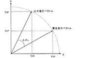
図20は電圧補正手段23の動作を示す図である。電圧補正手段23は電圧位相誤差演算部24を備える。電圧位相誤差演算手段24は変調率Vkに基づいて、電圧位相誤差Δθvを出力する。
FIG. 20 is a diagram illustrating the operation of the
ここで、図21に示すように、電圧ベクトルの長さは変わらず、電圧指令ベクトルと出力電圧ベクトルとの位相がΔθvずれていた場合、回転行列を用いて出力電圧ベクトルのdq軸電圧VdhおよびVqhは図20中に示すように次式(17)で求められる。 Here, as shown in FIG. 21, when the length of the voltage vector is not changed and the phase of the voltage command vector and the output voltage vector is shifted by Δθv, the dq axis voltage Vdh of the output voltage vector and Vqh is obtained by the following equation (17) as shown in FIG.
Δθvについては変調率Vkに依存する傾向にある。そのため、変調率VkとΔθvの関係を予め求めておき、これをテーブルにしメモリなどの記憶手段に格納しておき、必要時にこれを参照することで、マイコン等の処理装置の負荷を増加させることなく、Δθvを得ることができ、式(14)を用いて出力電圧ベクトルのdq軸電圧VdhおよびVqhを求めることが可能となる。式(6)のVd*およびVq*に代えてVdhおよびVqhを用いることで、より精度良く消費電力を求めることが可能となる。 Δθv tends to depend on the modulation rate Vk. Therefore, the relationship between the modulation factor Vk and Δθv is obtained in advance, stored in a storage means such as a memory in a table, and this is referred to when necessary, thereby increasing the load on a processing device such as a microcomputer. Therefore, Δθv can be obtained, and the dq-axis voltages Vdh and Vqh of the output voltage vector can be obtained using the equation (14). By using Vdh and Vqh instead of Vd * and Vq * in Expression (6), it is possible to obtain power consumption with higher accuracy.
つまり、制御周期を小さくできない安価なシステムにおいても、精度良く消費電力を求めることが可能となり、低コスト化が図れる。 That is, even in an inexpensive system in which the control cycle cannot be reduced, it is possible to obtain power consumption with high accuracy, and cost can be reduced.
ここで、実施の形態2に示す構成の場合、電圧補正手段23は変調率Vkに代えて補正変調率Vk'を用いても何ら問題ないことは言うまでもない。 Here, in the configuration shown in the second embodiment, it goes without saying that there is no problem even if the voltage correction means 23 uses the correction modulation rate Vk ′ instead of the modulation rate Vk.
実施の形態5.
以上の実施の形態1〜4で説明した電動機の駆動装置の活用例として、空気調和機や冷蔵庫などの冷凍空調装置などが挙げられる。
As examples of the use of the electric motor drive device described in the first to fourth embodiments, there are refrigeration air conditioners such as an air conditioner and a refrigerator.
冷凍空調装置は外気温度等の動作環境により、電動機の駆動装置にかかる負荷が大きく変化する特徴を有する。負荷が急変すると、電動機は負荷に耐えきれず脱調等の現象を起こす恐れがある。 The refrigerating and air-conditioning apparatus has a feature that the load applied to the driving device of the electric motor varies greatly depending on the operating environment such as the outside air temperature. If the load changes suddenly, the electric motor cannot withstand the load and may cause a phenomenon such as step-out.
そこで、実施の形態1〜4にて説明した消費電力演算手段11により得られた消費電力に基づいて脱調状態を検知することができ、脱調を検知して速やかに再起動することが可能となり、信頼性の高い冷凍空調装置を提供できる。
Therefore, the step-out state can be detected based on the power consumption obtained by the power
また、予め冷凍空調装置の最大消費電力を記憶しておき、その最大消費電力に到達する恐れがある場合、事前に電動機の回転数を低下させるなどの対策を行い、脱調を防止することで運転を継続させることも可能であり、信頼性の高い冷凍空調装置を提供できる。 Also, store the maximum power consumption of the refrigeration air conditioner in advance, and if there is a risk of reaching the maximum power consumption, take measures such as reducing the motor speed in advance to prevent step-out. The operation can be continued and a highly reliable refrigeration air conditioner can be provided.
さらに、予め使用する消費電力を決めておき、決められた消費電力を超えないように電動機を制御することで、消費電力を抑制することができ、CO2排出量も削減し、地球温暖化に考慮した冷凍空調装置を提供できる。 Furthermore, by determining the power consumption to be used in advance and controlling the electric motor so as not to exceed the determined power consumption, it is possible to suppress power consumption, reduce CO 2 emissions and reduce global warming. It is possible to provide a refrigeration air conditioner that takes into account.
本発明の活用例として、圧縮機用インバータや送風機用インバータが挙げられる。また、圧縮機を搭載する活用例として、空気調和機、冷蔵庫、冷凍機、除湿機、給湯機などが挙げられる。さらに、送風機を搭載する活用例として、換気扇、空気清浄機、加湿器などが挙げられる。 Examples of utilization of the present invention include compressor inverters and blower inverters. In addition, examples of utilizing a compressor include an air conditioner, a refrigerator, a refrigerator, a dehumidifier, and a hot water heater. Furthermore, a ventilation fan, an air cleaner, a humidifier, etc. are mentioned as an example of utilization which mounts an air blower.
1 直流電源、2 電動機の駆動装置、3 電動機、4 永久磁石、5 インバータ主回路、6 電流検出手段、7 直流電圧検出手段、8 インバータ制御手段、9 座標変換手段、10 電圧利用率演算手段、11 消費電力演算手段、12 印加電圧制御手段、13 速度補償手段、14 積分手段、15 電圧指令演算手段、16 変調率・位相指令演算手段、17 駆動信号生成手段、18 変調率補正手段、19 スイッチング素子、20 環流ダイオード、21 デッドタイム補正手段、22 電圧誤差推定手段、23 電圧補正手段、24 電圧位相誤差算出手段。
DESCRIPTION OF
Claims (16)
前記電動機に流れる相電流を検出する電流検出手段と、
前記インバータに印加される直流電圧を検出する直流電圧検出手段と、
前記インバータが電動機に印加する電圧を制御する制御手段と、
位相誤差記憶手段と、
を備え、
前記制御手段は、
前記電流検出手段が検出した相電流を直交2軸座標上の電流としてd軸電流Id及びq軸電流Iqに変換する座標変換手段と、
前記座標変換手段の出力と所定の基準値に基づき、前記電動機に印加する前記直交2軸座標上の電圧の指令値としてd軸電圧指令値Vd*及びq軸電圧指令値Vq*を出力する電圧指令値演算手段と、
前記直交2軸座標上の電圧指令値であるd軸電圧指令値Vd*及びq軸電圧指令値Vq*と、前記直流電圧とにより変調率を求める変調率演算手段と、
前記変調率演算手段の出力である前記変調率とその前記変調率に対する出力電圧の割合である電圧利用率を予め求めておき、前記変調率と前記電圧利用率との対応関係を記憶させ、前記電圧利用率を求めるときには、予め記憶させた前記対応関係に基づいて前記変調率から前記電圧利用率を求める電圧利用率演算手段と、
前記直交2軸座標上の電圧指令値であるd軸電圧指令値Vd*及びq軸電圧指令値Vq*と前記直交2軸座標上の電流であるd軸電流Id及びq軸電流Iqとの内積を求め、その求めた内積に対して、前記電圧利用率を乗算すると共に前記変調率を除算することにより、前記電動機の消費電力を求める消費電力演算手段と、
を備え、
前記位相誤差記憶手段は、
前記電動機に印加される電圧と前記電圧の指令値との位相誤差と、前記制御手段が有する変調率演算手段または前記制御手段が有する変調率補正手段の出力との関係を予め記憶し、
前記消費電力演算手段は、前記電動機の消費電力を求める際に前記位相誤差記憶手段に記憶された位相誤差に基づいて前記電圧指令値演算手段の出力を補正する
ことを特徴とする電動機の駆動装置。 An inverter that converts DC voltage to AC voltage and applies it to the motor;
Current detecting means for detecting a phase current flowing in the electric motor;
DC voltage detecting means for detecting a DC voltage applied to the inverter;
Control means for controlling the voltage applied to the electric motor by the inverter;
And phase error storage means,
Equipped with a,
Before Symbol control means,
Coordinate conversion means for converting the phase current detected by the current detection means into a d-axis current Id and a q-axis current Iq as a current on orthogonal two-axis coordinates;
A voltage that outputs a d-axis voltage command value Vd * and a q-axis voltage command value Vq * as a command value of a voltage on the orthogonal two-axis coordinate applied to the electric motor based on the output of the coordinate conversion means and a predetermined reference value. Command value calculation means;
A modulation rate calculation means for obtaining a modulation rate from the d-axis voltage command value Vd * and q-axis voltage command value Vq *, which are voltage command values on the orthogonal two-axis coordinates, and the DC voltage;
The modulation factor that is the output of the modulation factor calculator and a voltage utilization factor that is a ratio of the output voltage to the modulation factor are obtained in advance, and a correspondence relationship between the modulation factor and the voltage utilization factor is stored, When obtaining the voltage utilization factor, voltage utilization factor calculating means for obtaining the voltage utilization factor from the modulation factor based on the correspondence stored in advance,
The inner product of the d-axis voltage command value Vd * and q-axis voltage command value Vq *, which are voltage command values on the orthogonal two-axis coordinates, and the d-axis current Id and q-axis current Iq, which are currents on the orthogonal two-axis coordinates. Power consumption calculating means for determining the power consumption of the motor by multiplying the determined inner product by the voltage utilization factor and dividing the modulation factor;
With
The phase error storage means includes
Preliminarily storing the relationship between the phase error between the voltage applied to the electric motor and the command value of the voltage, and the output of the modulation factor correction unit included in the control unit or the modulation factor correction unit included in the control unit,
The electric power consumption calculation means corrects the output of the voltage command value calculation means based on the phase error stored in the phase error storage means when determining the electric power consumption of the electric motor. .
前記電動機に流れる相電流を検出する電流検出手段と、
前記インバータに印加される直流電圧を検出する直流電圧検出手段と、
前記インバータが電動機に印加する電圧を制御する制御手段と、
位相誤差記憶手段と、
を備え、
前記制御手段は、
前記電流検出手段が検出した相電流を直交2軸座標上の電流としてd軸電流Id及びq軸電流Iqに変換する座標変換手段と、
前記座標変換手段の出力と所定の基準値に基づき、前記電動機に印加する前記直交2軸座標上の電圧の指令値としてd軸電圧指令値Vd*及びq軸電圧指令値Vq*を出力する電圧指令値演算手段と、
前記直交2軸座標上の電圧指令値であるd軸電圧指令値Vd*及びq軸電圧指令値Vq*と、前記直流電圧とにより変調率を求める変調率演算手段と、
前記変調率演算手段の出力である前記変調率とその前記変調率に対する出力電圧の割合である電圧利用率を予め求めておき、前記変調率と前記電圧利用率との対応関係を記憶させ、前記電圧利用率を求めるときには、予め記憶させた前記対応関係に基づいて前記変調率から前記電圧利用率を求める電圧利用率演算手段と、
前記直交2軸座標上の電圧指令値であるd軸電圧指令値Vd*及びq軸電圧指令値Vq*と前記直交2軸座標上の電流であるd軸電流Id及びq軸電流Iqとの内積を求め、その求めた内積に対して、前記電圧利用率を乗算すると共に前記変調率を除算することにより、前記電動機の消費電力を求める消費電力演算手段と、
を備え、
前記位相誤差記憶手段は、
前記電動機に印加される電圧と前記電圧の指令値との位相誤差と、前記制御手段が有する変調率演算手段または前記制御手段が有する変調率補正手段の出力との関係を予め記憶し、
前記消費電力演算手段は、前記電動機の消費電力を求める際に前記位相誤差記憶手段に記憶された位相誤差に基づいて前記電圧指令値演算手段の出力を補正し、
前記消費電力演算手段は、前記変調率が1を超えた場合に、前記電圧指令値演算手段の出力を前記変調率で正規化し、更にこの正規化によって得られた結果に前記電圧利用率演算手段の出力を乗算して新たな電圧指令値に変換し、この変換後の電圧指令値に基づいて消費電力を演算することを特徴とする電動機の駆動装置。 An inverter that converts DC voltage to AC voltage and applies it to the motor;
Current detecting means for detecting a phase current flowing in the electric motor;
DC voltage detecting means for detecting a DC voltage applied to the inverter;
Control means for controlling the voltage applied to the electric motor by the inverter;
And phase error storage means,
Equipped with a,
Before Symbol control means,
Coordinate conversion means for converting the phase current detected by the current detection means into a d-axis current Id and a q-axis current Iq as a current on orthogonal two-axis coordinates;
A voltage that outputs a d-axis voltage command value Vd * and a q-axis voltage command value Vq * as a command value of a voltage on the orthogonal two-axis coordinate applied to the electric motor based on the output of the coordinate conversion means and a predetermined reference value. Command value calculation means;
A modulation rate calculation means for obtaining a modulation rate from the d-axis voltage command value Vd * and q-axis voltage command value Vq *, which are voltage command values on the orthogonal two-axis coordinates, and the DC voltage;
The modulation factor that is the output of the modulation factor calculator and a voltage utilization factor that is a ratio of the output voltage to the modulation factor are obtained in advance, and a correspondence relationship between the modulation factor and the voltage utilization factor is stored, When obtaining the voltage utilization factor, voltage utilization factor calculating means for obtaining the voltage utilization factor from the modulation factor based on the correspondence stored in advance,
The inner product of the d-axis voltage command value Vd * and q-axis voltage command value Vq *, which are voltage command values on the orthogonal two-axis coordinates, and the d-axis current Id and q-axis current Iq, which are currents on the orthogonal two-axis coordinates. Power consumption calculating means for determining the power consumption of the motor by multiplying the determined inner product by the voltage utilization factor and dividing the modulation factor;
With
The phase error storage means includes
Preliminarily storing the relationship between the phase error between the voltage applied to the electric motor and the command value of the voltage, and the output of the modulation factor correction unit included in the control unit or the modulation factor correction unit included in the control unit,
The power consumption calculation means corrects the output of the voltage command value calculation means based on the phase error stored in the phase error storage means when determining the power consumption of the electric motor,
The power consumption calculation means normalizes the output of the voltage command value calculation means with the modulation rate when the modulation rate exceeds 1, and further adds the voltage utilization rate calculation means to the result obtained by this normalization. The motor drive device is characterized in that the output is multiplied to be converted into a new voltage command value, and the power consumption is calculated based on the converted voltage command value.
前記電動機に流れる相電流を検出する電流検出手段と、
前記インバータに印加される直流電圧を検出する直流電圧検出手段と、
前記インバータが電動機に印加する電圧を制御する制御手段と、
位相誤差記憶手段と、
を備え、
前記制御手段は、
前記電流検出手段が検出した相電流を直交2軸座標上の電流としてd軸電流Id及びq軸電流Iqに変換する座標変換手段と、
前記座標変換手段の出力と所定の基準値に基づき、前記電動機に印加する前記直交2軸座標上の電圧の指令値としてd軸電圧指令値Vd*及びq軸電圧指令値Vq*を出力する電圧指令値演算手段と、
前記直交2軸座標上の電圧指令値であるd軸電圧指令値Vd*及びq軸電圧指令値Vq*と、前記直流電圧とにより変調率を求める変調率演算手段と、
前記変調率演算手段によって求められた変調率を補正して出力する変調率補正手段と、
前記変調率補正手段の出力である前記変調率とその前記変調率に対する出力電圧の割合である電圧利用率を予め求めておき、前記変調率と前記電圧利用率との対応関係を記憶させ、前記電圧利用率を求めるときには、予め記憶させた前記対応関係に基づいて前記変調率から前記電圧利用率を求める電圧利用率演算手段と、
前記直交2軸座標上の電圧指令値であるd軸電圧指令値Vd*及びq軸電圧指令値Vq*と前記直交2軸座標上の電流であるd軸電流Id及びq軸電流Iqとの内積を求め、その求めた内積に対して、前記電圧利用率を乗算すると共に前記変調率を除算することにより、前記電動機および前記インバータの消費電力を求める消費電力演算手段と、
を備え、
前記位相誤差記憶手段は、
前記電動機に印加される電圧と前記電圧の指令値との位相誤差と、前記制御手段が有する変調率演算手段または前記制御手段が有する変調率補正手段の出力との関係を予め記憶し、
前記消費電力演算手段は、前記電動機の消費電力を求める際に前記位相誤差記憶手段に記憶された位相誤差に基づいて前記電圧指令値演算手段の出力を補正する
ことを特徴とする電動機の駆動装置。 An inverter that converts DC voltage to AC voltage and applies it to the motor;
Current detecting means for detecting a phase current flowing in the electric motor;
DC voltage detecting means for detecting a DC voltage applied to the inverter;
Control means for controlling the voltage applied to the electric motor by the inverter;
And phase error storage means,
Equipped with a,
Before Symbol control means,
Coordinate conversion means for converting the phase current detected by the current detection means into a d-axis current Id and a q-axis current Iq as a current on orthogonal two-axis coordinates;
A voltage that outputs a d-axis voltage command value Vd * and a q-axis voltage command value Vq * as a command value of a voltage on the orthogonal two-axis coordinate applied to the electric motor based on the output of the coordinate conversion means and a predetermined reference value. Command value calculation means;
A modulation rate calculation means for obtaining a modulation rate from the d-axis voltage command value Vd * and q-axis voltage command value Vq *, which are voltage command values on the orthogonal two-axis coordinates, and the DC voltage;
Modulation rate correction means for correcting and outputting the modulation rate obtained by the modulation rate calculation means;
The modulation factor that is an output of the modulation factor correction means and a voltage utilization factor that is a ratio of an output voltage to the modulation factor are obtained in advance, and a correspondence relationship between the modulation factor and the voltage utilization factor is stored, When obtaining the voltage utilization factor, voltage utilization factor calculating means for obtaining the voltage utilization factor from the modulation factor based on the correspondence stored in advance,
The inner product of the d-axis voltage command value Vd * and q-axis voltage command value Vq *, which are voltage command values on the orthogonal two-axis coordinates, and the d-axis current Id and q-axis current Iq, which are currents on the orthogonal two-axis coordinates. Power consumption calculating means for determining power consumption of the electric motor and the inverter by multiplying the obtained inner product by the voltage utilization factor and dividing the modulation factor;
With
The phase error storage means includes
Preliminarily storing the relationship between the phase error between the voltage applied to the electric motor and the command value of the voltage, and the output of the modulation factor correction unit included in the control unit or the modulation factor correction unit included in the control unit,
The electric power consumption calculation means corrects the output of the voltage command value calculation means based on the phase error stored in the phase error storage means when determining the electric power consumption of the electric motor. .
前記制御手段は、前記デッドタイム電圧誤差推定手段の出力に基づいて前記電圧指令値演算手段の出力を補正することを特徴とする請求項1〜請求項6のいずれかに記載の電動機の駆動装置。 A dead time voltage error estimating means for estimating an error caused by a dead time of the inverter between a voltage applied to the electric motor and a command value of the voltage;
7. The motor drive apparatus according to claim 1, wherein the control unit corrects the output of the voltage command value calculation unit based on the output of the dead time voltage error estimation unit. .
前記制御手段は、前記脱調検出手段が前記電動機の脱調状態を検出すると、前記電動機を再起動することを特徴とする請求項1〜請求項11のいずれかに記載の電動機の駆動装置。 Based on the output of the power consumption calculation means, provided with a step-out detection means for detecting a step-out state of the motor,
The motor drive device according to any one of claims 1 to 11, wherein the control unit restarts the motor when the step-out detection unit detects a step-out state of the motor.
Priority Applications (1)
| Application Number | Priority Date | Filing Date | Title |
|---|---|---|---|
| JP2008233796A JP5116620B2 (en) | 2008-09-11 | 2008-09-11 | Electric motor drive device and refrigeration air conditioner |
Applications Claiming Priority (1)
| Application Number | Priority Date | Filing Date | Title |
|---|---|---|---|
| JP2008233796A JP5116620B2 (en) | 2008-09-11 | 2008-09-11 | Electric motor drive device and refrigeration air conditioner |
Publications (2)
| Publication Number | Publication Date |
|---|---|
| JP2010068662A JP2010068662A (en) | 2010-03-25 |
| JP5116620B2 true JP5116620B2 (en) | 2013-01-09 |
Family
ID=42193748
Family Applications (1)
| Application Number | Title | Priority Date | Filing Date |
|---|---|---|---|
| JP2008233796A Active JP5116620B2 (en) | 2008-09-11 | 2008-09-11 | Electric motor drive device and refrigeration air conditioner |
Country Status (1)
| Country | Link |
|---|---|
| JP (1) | JP5116620B2 (en) |
Families Citing this family (10)
| Publication number | Priority date | Publication date | Assignee | Title |
|---|---|---|---|---|
| JP5171925B2 (en) * | 2010-11-08 | 2013-03-27 | 三菱電機株式会社 | PWM inverter device |
| US9647601B2 (en) | 2013-08-12 | 2017-05-09 | Mitsubishi Electric Corporation | Motor control device |
| JP5983636B2 (en) * | 2014-01-10 | 2016-09-06 | ダイキン工業株式会社 | Electric motor control device |
| JP6667625B2 (en) * | 2016-05-18 | 2020-03-18 | 三菱電機株式会社 | Air conditioner |
| CN109496190B (en) * | 2016-07-20 | 2020-01-21 | 日本精工株式会社 | Electric power steering apparatus |
| CN109451781B (en) * | 2016-07-20 | 2020-01-31 | 日本精工株式会社 | Electric power steering apparatus |
| JP6667407B2 (en) * | 2016-09-12 | 2020-03-18 | ルネサスエレクトロニクス株式会社 | Control device |
| JP6719162B2 (en) * | 2017-06-28 | 2020-07-08 | 東芝三菱電機産業システム株式会社 | Multi-phase motor drive |
| CN111758215A (en) * | 2018-03-16 | 2020-10-09 | 日产自动车株式会社 | Motor control method and motor control device |
| KR102109575B1 (en) * | 2018-05-31 | 2020-05-12 | 엘에스일렉트릭(주) | Apparatus for controlling inverter |
Family Cites Families (9)
| Publication number | Priority date | Publication date | Assignee | Title |
|---|---|---|---|---|
| JP3669831B2 (en) * | 1998-01-14 | 2005-07-13 | 株式会社荏原製作所 | Inverter device |
| JP3951075B2 (en) * | 1998-02-13 | 2007-08-01 | 株式会社安川電機 | Method and apparatus for controlling motor |
| JP3565124B2 (en) * | 2000-01-12 | 2004-09-15 | トヨタ自動車株式会社 | Apparatus and method for determining step-out of synchronous motor |
| JP3644391B2 (en) * | 2001-02-15 | 2005-04-27 | 三菱電機株式会社 | Inverter device, compressor control device, refrigeration / air conditioning device control device, motor control method, compressor, refrigeration / air conditioning device |
| JP4135134B2 (en) * | 2002-04-15 | 2008-08-20 | 日産自動車株式会社 | Motor control device |
| JP2006191721A (en) * | 2005-01-05 | 2006-07-20 | Yaskawa Electric Corp | Motor controller and control method |
| JP4417323B2 (en) * | 2005-11-18 | 2010-02-17 | 三菱電機株式会社 | Motor control device |
| JP2007282367A (en) * | 2006-04-06 | 2007-10-25 | Matsushita Electric Ind Co Ltd | Motor driving controller |
| JP2007306694A (en) * | 2006-05-10 | 2007-11-22 | Yaskawa Electric Corp | Inverter controller of induction motor |
-
2008
- 2008-09-11 JP JP2008233796A patent/JP5116620B2/en active Active
Also Published As
| Publication number | Publication date |
|---|---|
| JP2010068662A (en) | 2010-03-25 |
Similar Documents
| Publication | Publication Date | Title |
|---|---|---|
| JP5116620B2 (en) | Electric motor drive device and refrigeration air conditioner | |
| JP4964209B2 (en) | Electric motor drive device and refrigeration air conditioner | |
| JP4053968B2 (en) | Synchronous motor driving device, refrigerator and air conditioner | |
| JP5222640B2 (en) | Refrigeration equipment | |
| JP3644391B2 (en) | Inverter device, compressor control device, refrigeration / air conditioning device control device, motor control method, compressor, refrigeration / air conditioning device | |
| JP2012228127A (en) | Motor controller | |
| JP6621356B2 (en) | Power conversion device, motor drive device, and refrigeration equipment using the same | |
| WO2015129590A1 (en) | Supercharger and ship | |
| JP2015128355A (en) | Motor controller | |
| KR101514391B1 (en) | Vector controller and motor controller using the same, air-conditioner | |
| TWI355477B (en) | ||
| JP5635032B2 (en) | Synchronous motor drive device and blower using the same | |
| JP4804496B2 (en) | Electric motor drive, air conditioner, washing machine, washing dryer, refrigerator, ventilation fan, heat pump water heater | |
| JP4744505B2 (en) | Motor drive control device, motor drive control method and coordinate conversion method, ventilation fan, liquid pump, blower, refrigerant compressor, air conditioner, and refrigerator | |
| JP6463966B2 (en) | Motor driving device, motor driving module and refrigeration equipment | |
| US20180241336A1 (en) | Power converting apparatus and heat pump device | |
| JP2010068581A (en) | Electric motor drive unit | |
| JP2008148437A (en) | Controller for permanent magnet type synchronous motor | |
| JP2004040861A (en) | Driving-gear of motor | |
| JP6005429B2 (en) | Motor control device and control method | |
| KR102580148B1 (en) | Motor driving apparatus and freezing equipment | |
| JP6309173B2 (en) | Motor drive device, heat pump device using the motor drive device, refrigeration air conditioner, and blower | |
| JP6490540B2 (en) | Rotation position detection device, air conditioner, and rotation position detection method | |
| JP2011147306A (en) | Electric motor control circuit, and air conditioner using the same | |
| JP5078925B2 (en) | Electric motor drive device and equipment |
Legal Events
| Date | Code | Title | Description |
|---|---|---|---|
| A977 | Report on retrieval |
Free format text: JAPANESE INTERMEDIATE CODE: A971007 Effective date: 20110622 |
|
| A131 | Notification of reasons for refusal |
Free format text: JAPANESE INTERMEDIATE CODE: A131 Effective date: 20110628 |
|
| A521 | Request for written amendment filed |
Free format text: JAPANESE INTERMEDIATE CODE: A523 Effective date: 20110822 |
|
| A02 | Decision of refusal |
Free format text: JAPANESE INTERMEDIATE CODE: A02 Effective date: 20120228 |
|
| A521 | Request for written amendment filed |
Free format text: JAPANESE INTERMEDIATE CODE: A523 Effective date: 20120508 |
|
| A911 | Transfer to examiner for re-examination before appeal (zenchi) |
Free format text: JAPANESE INTERMEDIATE CODE: A911 Effective date: 20120515 |
|
| A131 | Notification of reasons for refusal |
Free format text: JAPANESE INTERMEDIATE CODE: A131 Effective date: 20120807 |
|
| A521 | Request for written amendment filed |
Free format text: JAPANESE INTERMEDIATE CODE: A523 Effective date: 20120829 |
|
| TRDD | Decision of grant or rejection written | ||
| A01 | Written decision to grant a patent or to grant a registration (utility model) |
Free format text: JAPANESE INTERMEDIATE CODE: A01 Effective date: 20121009 |
|
| A01 | Written decision to grant a patent or to grant a registration (utility model) |
Free format text: JAPANESE INTERMEDIATE CODE: A01 |
|
| A61 | First payment of annual fees (during grant procedure) |
Free format text: JAPANESE INTERMEDIATE CODE: A61 Effective date: 20121016 |
|
| R150 | Certificate of patent or registration of utility model |
Ref document number: 5116620 Country of ref document: JP Free format text: JAPANESE INTERMEDIATE CODE: R150 Free format text: JAPANESE INTERMEDIATE CODE: R150 |
|
| FPAY | Renewal fee payment (event date is renewal date of database) |
Free format text: PAYMENT UNTIL: 20151026 Year of fee payment: 3 |
|
| R250 | Receipt of annual fees |
Free format text: JAPANESE INTERMEDIATE CODE: R250 |
|
| R250 | Receipt of annual fees |
Free format text: JAPANESE INTERMEDIATE CODE: R250 |
|
| R250 | Receipt of annual fees |
Free format text: JAPANESE INTERMEDIATE CODE: R250 |
|
| R250 | Receipt of annual fees |
Free format text: JAPANESE INTERMEDIATE CODE: R250 |
|
| R250 | Receipt of annual fees |
Free format text: JAPANESE INTERMEDIATE CODE: R250 |
|
| R250 | Receipt of annual fees |
Free format text: JAPANESE INTERMEDIATE CODE: R250 |
|
| R250 | Receipt of annual fees |
Free format text: JAPANESE INTERMEDIATE CODE: R250 |
|
| R250 | Receipt of annual fees |
Free format text: JAPANESE INTERMEDIATE CODE: R250 |
|
| R250 | Receipt of annual fees |
Free format text: JAPANESE INTERMEDIATE CODE: R250 |