JP4854331B2 - Fluid mixing device - Google Patents

Fluid mixing device Download PDF

Info

Publication number
JP4854331B2
JP4854331B2 JP2006055235A JP2006055235A JP4854331B2 JP 4854331 B2 JP4854331 B2 JP 4854331B2 JP 2006055235 A JP2006055235 A JP 2006055235A JP 2006055235 A JP2006055235 A JP 2006055235A JP 4854331 B2 JP4854331 B2 JP 4854331B2
Authority
JP
Japan
Prior art keywords
valve
fluid
diaphragm
flow rate
main body
Prior art date
Legal status (The legal status is an assumption and is not a legal conclusion. Google has not performed a legal analysis and makes no representation as to the accuracy of the status listed.)
Expired - Fee Related
Application number
JP2006055235A
Other languages
Japanese (ja)
Other versions
JP2007175691A5 (en
JP2007175691A (en
Inventor
清志 黒沢
典宏 野田
Current Assignee (The listed assignees may be inaccurate. Google has not performed a legal analysis and makes no representation or warranty as to the accuracy of the list.)
Asahi Yukizai Corp
Original Assignee
Asahi Organic Chemicals Industry Co Ltd
Priority date (The priority date is an assumption and is not a legal conclusion. Google has not performed a legal analysis and makes no representation as to the accuracy of the date listed.)
Filing date
Publication date
Application filed by Asahi Organic Chemicals Industry Co Ltd filed Critical Asahi Organic Chemicals Industry Co Ltd
Priority to JP2006055235A priority Critical patent/JP4854331B2/en
Priority to US11/646,596 priority patent/US20070204914A1/en
Priority to KR1020070007538A priority patent/KR20070090079A/en
Publication of JP2007175691A publication Critical patent/JP2007175691A/en
Publication of JP2007175691A5 publication Critical patent/JP2007175691A5/ja
Priority to US12/899,950 priority patent/US20110044125A1/en
Application granted granted Critical
Publication of JP4854331B2 publication Critical patent/JP4854331B2/en
Expired - Fee Related legal-status Critical Current
Anticipated expiration legal-status Critical

Links

Images

Landscapes

  • Accessories For Mixers (AREA)
  • Flow Control (AREA)
  • Control Of Fluid Pressure (AREA)

Description

本発明は2ライン以上の流体を任意の比率で混合させる流体輸送配管に使用される流体混合装置に関するものである。さらに詳しくは、各ラインの流体の流量を制御して流体を任意の比率で混合させると共に、脈動した流体が流れても問題なく流量制御することができ、コンパクトな構成で狭いスペースに設置可能であり、設置における配管及び配線接続が容易である流体混合装置に関するものである。   The present invention relates to a fluid mixing device used in a fluid transport pipe for mixing two or more lines of fluid at an arbitrary ratio. More specifically, the flow rate of the fluid in each line is controlled to mix the fluid at an arbitrary ratio, and even if the pulsating fluid flows, the flow rate can be controlled without any problem, and it can be installed in a narrow space with a compact configuration. In addition, the present invention relates to a fluid mixing apparatus that facilitates piping and wiring connection in installation.

従来、半導体製造工程の一工程として、フッ酸等の薬液を純水で希釈した洗浄水を用いてウェハ表面をエッチングする湿式エッチングが用いられている。これら湿式エッチングの洗浄水の濃度は高い精度をもって管理する必要があるとされている。近年では、洗浄水の濃度を、純水と薬液の流量比で管理する方法が主流となってきており、そのために、純水や薬液の流量を高い精度をもって管理する流体混合装置が適用されている。   Conventionally, wet etching, in which a wafer surface is etched using cleaning water obtained by diluting a chemical solution such as hydrofluoric acid with pure water, is used as one step of a semiconductor manufacturing process. It is said that the concentration of cleaning water for these wet etching needs to be managed with high accuracy. In recent years, the method of managing the concentration of cleaning water by the flow rate ratio of pure water and chemical liquid has become the mainstream, and for this reason, fluid mixing devices that manage the flow volume of pure water and chemical liquid with high accuracy have been applied. Yes.

流体混合装置として種々提案されているが、図31に示される多系統流量制御装置及びその制御方法があった(例えば、特許文献1参照)。その構成は、複数の流体流入系統601をそれぞれ流量調整する複数のアクチュエータ602に対して、それぞれ、操作信号を出力して制御することで合流流体流量が目標流量となるように制御する流量制御装置において、前記流量制御装置は、前記複数のアクチュエータ602のうちの1つを除いた他のアクチュエータ602b〜602nに流量が略一定となるように操作信号を出力し、前記複数のアクチュエータ602のうちの1つに合流流体流量が目標値となるように操作信号を出力するように構成したものであった。このとき、各々独立した複数の流体流入系統601から合流して流入する合流流体流量を制御する流量制御装置において、各流体流入系統601の検出流量の合算値と目標値との偏差からフィードバック演算して調節信号を出力する演算手段603と、前記演算手段603の調節信号が上下限の値となった場合に流体流入系統601を1系統選択すると共に、他のアクチュエータ602b〜602nから前記選択された1系統のアクチュエータ602aに切替えて前記調節信号を操作信号として出力する制御系統判定手段604を有するものであった。   Although various proposals have been made as fluid mixing devices, there has been a multi-system flow rate control device and a control method thereof shown in FIG. 31 (see, for example, Patent Document 1). The configuration is a flow rate control device that controls the combined fluid flow rate to be the target flow rate by controlling each of the plurality of actuators 602 that respectively adjust the flow rate of the multiple fluid inflow systems 601 by outputting an operation signal. The flow control device outputs an operation signal to the other actuators 602b to 602n excluding one of the plurality of actuators 602 so that the flow rate becomes substantially constant, One is configured to output an operation signal so that the combined fluid flow rate becomes a target value. At this time, in the flow rate control device that controls the flow rate of the combined fluid that flows from the plurality of independent fluid inflow systems 601, feedback calculation is performed from the deviation between the sum of the detected flow rates of the fluid inflow systems 601 and the target value. Calculating means 603 for outputting the adjustment signal, and when the adjustment signal of the calculating means 603 reaches the upper and lower limit values, one fluid inflow system 601 is selected and the other actuators 602b to 602n are selected. Control system determination means 604 that switches to one system of actuators 602a and outputs the adjustment signal as an operation signal is provided.

特開2004−133642号公報JP 2004-133642 A

しかしながら、前記従来の多系統流量制御装置及びその制御方法は、各流体流入系統601の流量の合計を目標流量にするものであり、各々の流体流入系統601が単独で制御されないため、少なくとも二つの流体を任意の比率に混合するための制御を行うことはできない。また、各流体流入系統601に脈動した流体が流れた場合、安定した流体制御が行えなくなる問題や、流量範囲を広くとれない構成なので幅広い流量範囲で流量を制御する用途には使いにくいという問題があった。また、制御装置の構成要素が多く分かれているため制御装置自体が大きくなり設置に場所をとる問題や、各構成要素は部材ごとに分かれており、配管接続作業、電気配線やエア配管作業をそれぞれ行なわなくてはならず、作業が複雑で時間を要し、配管や配線が煩わしくミスが起こる恐れがあるという問題があった。   However, the conventional multi-system flow rate control device and its control method are intended to set the total flow rate of each fluid inflow system 601 to the target flow rate, and each fluid inflow system 601 is not controlled independently, so at least two There is no control to mix the fluid in any ratio. In addition, when a pulsating fluid flows in each fluid inflow system 601, there is a problem that stable fluid control cannot be performed, and a problem that it is difficult to use for controlling the flow rate in a wide flow rate range because the flow rate range cannot be widened. there were. In addition, there are many components of the control device, so the control device itself becomes large and takes up space for installation, and each component is divided by member, and piping connection work, electrical wiring and air piping work are each There is a problem that the work is complicated and time-consuming, and the piping and wiring are troublesome and a mistake may occur.

本発明は、以上のような従来技術の問題点に鑑みなされたものであり、主として各ラインの流体の流量を制御して流体を任意の比率で混合させると共に、脈動した流体が流れても問題なく流量制御することができ、コンパクトな構成で狭いスペースに設置可能であり、設置における配管及び配線接続が容易である流体混合装置を提供することを目的とする。   The present invention has been made in view of the above-described problems of the prior art, and mainly controls the flow rate of fluid in each line to mix the fluid at an arbitrary ratio, and even if pulsating fluid flows. An object of the present invention is to provide a fluid mixing apparatus that can control the flow rate without any problem, can be installed in a narrow space with a compact configuration, and can be easily connected to piping and wiring in the installation.

上記課題を解決するための本発明の流体混合装置の構成を図に基づいて説明すると、少なくとも2つの供給ライン1、2に流れる各々の流体を任意の比率で混合させる流体混合装置であって、前記供給ライン1、2の少なくとも一つが、制御用流体の圧力操作により流体の圧力を制御する第一流体制御弁4と、流体の実流量を計測し該実流量の計測値を電気信号に変換し出力する流量計測器3と、該実流量の計測値と設定流量値との偏差に基づいて、第一流体制御弁4の開口面積を制御するための指令信号を、第一流体制御弁4または第一流体制御弁4を操作する機器へ出力する制御部5とをそれぞれ具備し、且つ前記供給ライン1、2の少なくとも一つが、流路の開口面積を変化させることにより流体の流量を制御する第二流体制御弁10と、流体の実流量を計測し該実流量の計測値を電気信号に変換し出力する流量計測器9と、該実流量の計測値と設定流量値との偏差に基づいて、第二流体制御弁10の開口面積を制御するための指令信号を、第二流体制御弁10または第二流体制御弁10を操作する機器へ出力する制御部11とをそれぞれ具備し、さらに、各々の前記供給ライン1、2の中の任意の一つの供給ラインの最上流側に接続される開閉弁535aが設けられた主ラインと、他の供給ラインの最上流側に接続される開閉弁536aが設けられた少なくとも一つの他のラインとを具備し、主ラインの開閉弁535aの上流側と他のラインの開閉弁536aの下流側とが開閉弁537aを介して連通されてなるフラッシング装置43を具備してなることを第1の特徴とする。
The configuration of the fluid mixing apparatus of the present invention for solving the above problems will be described with reference to the drawings. The fluid mixing apparatus mixes each fluid flowing in at least two supply lines 1 and 2 at an arbitrary ratio. At least one of the supply lines 1 and 2 includes a first fluid control valve 4 that controls the pressure of the fluid by controlling the pressure of the control fluid, and measures the actual flow rate of the fluid and converts the measured value of the actual flow rate into an electrical signal. And a command signal for controlling the opening area of the first fluid control valve 4 based on a deviation between the measured value of the actual flow rate and the set flow rate value, and the first fluid control valve 4 Or a control unit 5 that outputs to the device that operates the first fluid control valve 4, and at least one of the supply lines 1 and 2 controls the flow rate of the fluid by changing the opening area of the flow path. Second fluid control valve 10 A flow rate measuring device 9 that measures the actual flow rate of the fluid, converts the measured value of the actual flow rate into an electrical signal, and outputs it, and a second fluid control valve based on the deviation between the measured value of the actual flow rate and the set flow rate value. And a control unit 11 that outputs a command signal for controlling the opening area of the second fluid control valve 10 or a device that operates the second fluid control valve 10 to each other, and each of the supply lines 1 2, at least a main line provided with an on-off valve 535a connected to the uppermost stream side of any one supply line and an on-off valve 536a connected to the uppermost stream side of another supply line. And a flushing device 43 in which the upstream side of the opening / closing valve 535a of the main line and the downstream side of the opening / closing valve 536a of the other line are communicated via the opening / closing valve 537a. Is the first feature .

また、各々の前記供給ライン1、2が、流体の流れを開放又は遮断するための開閉弁18、22をさらに具備することを第2の特徴とする。   Each of the supply lines 1 and 2 further includes on-off valves 18 and 22 for opening or shutting off the fluid flow.

また、前記第二流体制御弁10を有する供給ライン2が、流体の圧力変動を減衰させる圧力調整弁35をさらに具備することを第3の特徴とする。   A third feature is that the supply line 2 having the second fluid control valve 10 further includes a pressure regulating valve 35 for attenuating the pressure fluctuation of the fluid.

また、前記第一流体制御弁3を有する供給ライン1が、開口面積が調節可能な絞り弁32をさらに具備することを第4の特徴とする。   The supply line 1 having the first fluid control valve 3 further includes a throttle valve 32 having an adjustable opening area.

また、各々の前記供給ライン1、2の最下流側に、該供給ライン1、2の合流部15を有することを第5の特徴とする。   Further, a fifth feature is that a joining portion 15 of the supply lines 1 and 2 is provided on the most downstream side of the supply lines 1 and 2.

また、前記合流部15直前の該供給ライン1、2に、開閉弁40、41がそれぞれ配置されてなることを第6の特徴とする。   A sixth feature is that on-off valves 40 and 41 are respectively arranged in the supply lines 1 and 2 immediately before the junction 15.

また、前記合流部15が、該供給ライン1、2を一つの流路に合流させるマニホールド弁42であることを第7の特徴とする。   Further, a seventh feature is that the merging portion 15 is a manifold valve 42 that merges the supply lines 1 and 2 into one flow path.

また、前記各種弁および前記流量計測器が、独立した接続手段を用いずに直接接続されていることを第の特徴とする。
Further, an eighth feature is that the various valves and the flow rate measuring device are directly connected without using independent connecting means.

また、前記各種弁および前記流量計測器が、一つのベースブロックに配設されていることを第の特徴とする。
The ninth feature is that the various valves and the flow rate measuring device are arranged in one base block.

また、前記各種弁および前記流量計測器が、一つのケーシング内に収納配設されていることを第10の特徴とする。
The tenth feature is that the various valves and the flow rate measuring device are accommodated in one casing.

また、前記第一流体制御弁4が、下部中央に底部まで開放して設けられた第二の空隙209と第二の空隙209に連通する入口流路211と上部に上面が開放して設けられ第二の空隙209の径よりも大きい径を持つ第一の空隙210と第一の空隙210に連通する出口流路212と第一の空隙210と第二の空隙209とを連通し第一の空隙210の径よりも小さい径を有する連通孔213とを有し、第二の空隙209の上面が弁座214とされた本体201と、側面あるいは上面に設けられた給気孔217と排出孔218とに連通した円筒状の空隙215を内部に有し、下端内周面に段差部216が設けられたボンネット202と、ボンネット202の段差部216に嵌挿され中央部に貫通孔219を有するバネ受け203と、下端部にバネ受け203の貫通孔219より小径の第一接合部224を有し上部に鍔部222が設けられボンネット202の空隙215内部に上下動可能に嵌挿されたピストン204と、ピストン204の鍔部222下端面とバネ受け203の上端面で挟持支承されているバネ205と、周縁部が本体201とバネ受け203との間で挟持固定され、本体201の第一の空隙210に蓋する形で第一の弁室231を形成する中央部が肉厚とされた第一ダイヤフラム227と、上面中央にピストン204の第一接合部224にバネ受け203の貫通孔219を貫通して接合固定される第二接合部229と、下面中央に本体201の連通孔213と貫通して設けられた第三接合部230とを有する第一弁機構体206と、本体の第二の空隙209内部に位置し本体の連通孔213より大径に設けられた弁体232と、弁体232上端面に突出して設けられ第一弁機構体206の第三接合部230と接合固定される第四接合部234と、弁体232下端面より突出して設けられたロッド235と、ロッド235下端面より径方向に延出して設けられた第二ダイヤフラム237とを有する第二弁機構体207と、本体201の下方に位置し第二弁機構体207の第二ダイヤフラム237周縁部を本体201との間で挟持固定する突出部239を上部中央に有し、突出部239の上端部に切欠凹部240が設けられると共に切欠凹部240に連通する呼吸孔241が設けられているベースプレート208とを具備し、ピストン204の上下動に伴って第二弁機構体207の弁体232と本体201の弁座214とによって形成される流体制御部242の開口面積が変化するように構成されていることを第11の特徴とする。
Further, the first fluid control valve 4 is provided with a second gap 209 provided at the bottom center and opened to the bottom, an inlet channel 211 communicating with the second gap 209 and an upper face opened at the top. The first gap 210 having a diameter larger than the diameter of the second gap 209, the outlet channel 212 communicating with the first gap 210, the first gap 210, and the second gap 209 are communicated with each other. A main body 201 having a communication hole 213 having a diameter smaller than the diameter of the gap 210, the upper surface of the second gap 209 being the valve seat 214, and an air supply hole 217 and a discharge hole 218 provided on the side surface or the upper face. A bonnet 202 having a cylindrical gap 215 communicated with the inside, a stepped portion 216 provided on the inner peripheral surface of the lower end, and a spring having a through-hole 219 inserted into the stepped portion 216 of the bonnet 202. The receiver 203 and the lower end A piston 204 having a first joint portion 224 having a smaller diameter than the through-hole 219 of the neck support 203 and having a flange portion 222 provided at the upper portion thereof and fitted in the space 215 of the bonnet 202 so as to be movable up and down; 222, a spring 205 sandwiched and supported by the lower end surface of the spring receiver 203 and the upper end surface of the spring receiver 203, and a peripheral portion is clamped and fixed between the main body 201 and the spring receiver 203 so as to cover the first gap 210 of the main body 201. A first diaphragm 227 having a thick central portion forming the first valve chamber 231 and a through hole 219 of the spring receiver 203 are joined and fixed to the first joint portion 224 of the piston 204 at the center of the upper surface. A first valve mechanism 206 having a second joint 229 and a third joint 230 provided through the communication hole 213 of the main body 201 at the center of the lower surface, and a second gap 209 in the main body. A valve body 232 having a larger diameter than the communication hole 213 of the main body, and a fourth joint portion 234 that projects from the upper end surface of the valve body 232 and is joined and fixed to the third joint portion 230 of the first valve mechanism 206. A second valve mechanism 207 having a rod 235 protruding from the lower end surface of the valve body 232, and a second diaphragm 237 extending in the radial direction from the lower end surface of the rod 235; Is located at the center of the upper portion of the second valve mechanism 207 and sandwiches and fixes the peripheral portion of the second diaphragm 237 with the main body 201. A notch recess 240 is provided at the upper end of the protrusion 239. And a base plate 208 provided with a breathing hole 241 communicating with the cutout recess 240, and the valve body 232 of the second valve mechanism 207 and the valve seat of the main body 201 as the piston 204 moves up and down. The eleventh feature is that the opening area of the fluid control unit 242 formed by the control unit 214 is changed.

また、前記第一流体制御弁4が、流体の入口流路145、出口流路152及び、入口流路145と出口流路152が連通するチャンバ127から形成された本体部121と、弁体165と第一ダイヤフラム部137を有する弁部材136と、弁部材136の下部及び上部に位置し第一ダイヤフラム部137より有効受圧面積が小さい第二ダイヤフラム部138及び第三ダイヤフラム部139を有し、弁部材136及び各ダイヤフラム部137、138、139が各ダイヤフラム部137、138、139の外周部が本体部121に固定されることによりチャンバ127内に取りつけられ、かつ各ダイヤフラム部137、138、139によってチャンバ127を第一加圧室128、第二弁室129、第一弁室130、及び第二加圧室131に区分し、第一加圧室128は第二ダイヤフラム部138に対して常時内向きの一定の力を加える手段を有し、第一弁室130は入口流路145と連通しており、第二弁室129は、弁部材136の弁体165に対応する弁座150を有し、また弁座150に対して第一ダイヤフラム部137側に位置し第一ダイヤフラム部137に設けられた連通孔162にて第一弁室130と連通している下部第二弁室132と、第二ダイヤフラム部138側に位置し出口流路152と連通して設けられた上部第二弁室133とに分かれて形成され、弁部材136の上下動により弁体165と弁座150との間の開口面積が変化して下部第二弁室134の流体圧力が制御される流体制御部168を有し、第二加圧室131は、第三ダイヤフラム部139に対して常時内向きの一定の力を加える手段を有することを第12の特徴とする。
Further, the first fluid control valve 4 includes a main body 121 formed of a fluid inlet channel 145, an outlet channel 152, a chamber 127 in which the inlet channel 145 and the outlet channel 152 communicate with each other, and a valve body 165. And a valve member 136 having a first diaphragm portion 137, and a second diaphragm portion 138 and a third diaphragm portion 139 which are located below and above the valve member 136 and have a smaller effective pressure receiving area than the first diaphragm portion 137, The member 136 and the diaphragm portions 137, 138, and 139 are attached to the chamber 127 by fixing the outer peripheral portions of the diaphragm portions 137, 138, and 139 to the main body portion 121, and the diaphragm portions 137, 138, and 139 The chamber 127 is changed to the first pressurizing chamber 128, the second valve chamber 129, the first valve chamber 130, and the second pressurizing chamber 131. The first pressurizing chamber 128 has means for constantly applying a constant inward force to the second diaphragm portion 138, the first valve chamber 130 is in communication with the inlet flow path 145, The valve chamber 129 has a valve seat 150 corresponding to the valve body 165 of the valve member 136, and is located on the first diaphragm portion 137 side with respect to the valve seat 150, and a communication hole 162 provided in the first diaphragm portion 137. Are divided into a lower second valve chamber 132 communicating with the first valve chamber 130 and an upper second valve chamber 133 provided on the second diaphragm portion 138 side and provided in communication with the outlet channel 152. And a fluid control unit 168 in which the opening area between the valve body 165 and the valve seat 150 is changed by the vertical movement of the valve member 136 and the fluid pressure in the lower second valve chamber 134 is controlled. The pressurizing chamber 131 is connected to the third diaphragm portion 139. And twelfth feature of further comprising a means for applying a constant force at all times inward Te.

また、前記第二流体制御弁10が、上部に弁室310と、弁室310に各々が連通している入口流路311および出口流路312とを有し、弁室310底部中央に入口流路311が連通している開口部313が設けられた本体301と、底部中央に貫通孔315と、側面に呼吸口316が設けられ、本体301と第一ダイヤフラム304を挟持固定しているシリンダー302および上部に作動流体連通口317が設けられ、シリンダー302と第二ダイヤフラム306の周縁部を挟持固定しているボンネット303が一体的に固定されており、第一ダイヤフラム304は肩部319と、肩部319の上に位置し後記ロッド307の下部に嵌合固定される取り付け部320、肩部319の下に位置し後記弁体305が固定される接合部332、肩部319から径方向に延出した薄膜部321、薄膜部321に続く厚肉部322および厚肉部322の周縁部に設けられたシール部323が一体的に形成され、接合部332には弁室310の開口部313に後記ロッド307の上下動に伴って出入りする弁体305が固定されており、一方、第二ダイヤフラム306は中央穴324を有し、その周辺の厚肉部325と、厚肉部325から径方向に延出した薄膜部326および薄膜部326の周縁部に設けられたシール部327が一体的に形成され、底部に第一ダイヤフラム304の取り付け部320が固定されているロッド307の上部に位置する肩部329にダイヤフラム押え308により中央穴324を貫通して挟持固定されており、また、ロッド307は、その下方部がシリンダー302底部の貫通孔315内に遊嵌状態に配置され、かつ、シリンダー302の段差部335とロッド307の肩部329下面との間に径方向への移動が防止された状態で嵌合されたスプリング309で支承されていることを第13の特徴とする。
The second fluid control valve 10 has a valve chamber 310 at the top, an inlet channel 311 and an outlet channel 312 each communicating with the valve chamber 310, and an inlet flow at the bottom center of the valve chamber 310. A main body 301 provided with an opening 313 through which a passage 311 communicates, a cylinder 302 provided with a through hole 315 at the center of the bottom, and a breathing port 316 provided on a side surface, and sandwiching and fixing the main body 301 and the first diaphragm 304. Further, a working fluid communication port 317 is provided at the upper portion, and a bonnet 303 that clamps and fixes the peripheral portion of the cylinder 302 and the second diaphragm 306 is integrally fixed. The first diaphragm 304 includes a shoulder portion 319, A mounting portion 320 that is located above the portion 319 and is fitted and fixed to the lower portion of the rod 307, and a joint portion 332 that is located below the shoulder portion 319 and to which the valve body 305 is fixed. A thin film portion 321 extending in the radial direction from the portion 319, a thick portion 322 following the thin film portion 321, and a seal portion 323 provided at a peripheral portion of the thick portion 322 are integrally formed. A valve body 305 that enters and exits as the rod 307 moves up and down is fixed to the opening 313 of the chamber 310, while the second diaphragm 306 has a central hole 324, The thin film portion 326 extending in the radial direction from the thick wall portion 325 and the seal portion 327 provided at the peripheral edge of the thin film portion 326 are integrally formed, and the attachment portion 320 of the first diaphragm 304 is fixed to the bottom portion. The shoulder 329 located at the upper part of the rod 307 is clamped and fixed through the center hole 324 by the diaphragm presser 308, and the lower part of the rod 307 is a cylinder. 02 is placed in a loosely fitted state in the through-hole 315 at the bottom, and is fitted between the stepped portion 335 of the cylinder 302 and the lower surface of the shoulder 329 of the rod 307 in a state where movement in the radial direction is prevented. A thirteenth feature is that it is supported by a spring 309.

また、前記第二流体制御弁10が、上部ボンネット358と下部ボンネット357に内包されたモータ部359とを有する電気式駆動部344と、モータ部359の軸に連結されたステム365により上下動される弁体343を有するダイヤフラム342と、ダイヤフラム342によって電気式駆動部344から隔離された弁室345に各々連通する入口流路346及び出口流路347を有する本体341とを具備する流量制御部からなることを第14の特徴とする。
The second fluid control valve 10 is moved up and down by an electric drive unit 344 having a motor unit 359 included in an upper bonnet 358 and a lower bonnet 357, and a stem 365 connected to the shaft of the motor unit 359. A flow rate control unit including a diaphragm 342 having a valve body 343 and a main body 341 having an inlet channel 346 and an outlet channel 347 respectively communicating with a valve chamber 345 isolated from the electric drive unit 344 by the diaphragm 342. This is the fourteenth feature.

また、前記第二流体制御弁10が、弾性体からなる管体401と、内部シリンダー部408を有し上部にシリンダー蓋409が一体的に設けられたシリンダー本体402と、シリンダー部408内周面に上下動可能且つ密封状態で摺接され且つシリンダー本体402下面中央に設けられた貫通孔410を密封状態で貫通するように中央より垂下して設けられた連結部416を有するピストン403と、ピストン403の連結部416の下端部に固定されシリンダー本体402の底面に流路軸線と直交して設けられた長円状スリット411内に収納される挟圧子404と、シリンダー本体402の下端面に接合固定され、流路軸線上に管体401を受容する第1の溝418と第1の溝418の両端部にさらに連結体受け406を受容する第2の溝419が第1の溝418よりも深く設けられた本体405と、一端に本体405の第2の溝419と嵌合する嵌合部421を有し他端内部に連結体407受口423を有しさらに管体401を受容する貫通孔426を有する一対の連結体受け406と、シリンダー本体402周側面に設けられ、シリンダー部408底面及び内周面とピストン403下端面とで囲まれて形成された第一空間部412と、シリンダー蓋409下端面とシリンダー部408内周面とピストン403上面とで囲まれた第二空間部413とにそれぞれ連通される一対のエアー口414、415を具備することを第15の特徴とする。
The second fluid control valve 10 includes a tubular body 401 made of an elastic body, a cylinder body 402 having an internal cylinder portion 408 and a cylinder lid 409 integrally provided on the upper portion, and an inner peripheral surface of the cylinder portion 408. A piston 403 having a connecting portion 416 provided so as to be vertically movable and slidably contacted in a sealed state and penetrating from the center so as to pass through a through hole 410 provided in the center of the lower surface of the cylinder body 402 in a sealed state; A clamper 404 that is fixed to the lower end of the connecting portion 416 of 403 and is accommodated in an elliptical slit 411 provided on the bottom surface of the cylinder body 402 at right angles to the flow path axis, and joined to the lower end surface of the cylinder body 402 A first groove 418 that is fixed and receives the tube 401 on the flow path axis, and a second groove 418 that receives a connector receiver 406 at both ends of the first groove 418. 419 has a main body 405 provided deeper than the first groove 418, a fitting portion 421 that fits into the second groove 419 of the main body 405 at one end, and a connecting body 407 receiving port 423 inside the other end. In addition, a pair of connecting body receivers 406 having a through hole 426 for receiving the tube body 401, and provided on the peripheral side surface of the cylinder body 402, are formed by being surrounded by the bottom surface and inner peripheral surface of the cylinder portion 408 and the lower end surface of the piston 403. And a pair of air ports 414 and 415 communicated with the second space portion 413 surrounded by the lower end surface of the cylinder lid 409, the inner peripheral surface of the cylinder portion 408, and the upper surface of the piston 403, respectively. This is the fifteenth feature.

また、前記第二流体制御弁10が、上部ボンネット451と下部ボンネット450に内包されたモータ部452とを有する電気式駆動部441と、モータ部452の軸に連結されたステム460により上下動される挟圧子449と、弾性体からなる管体443と、下部ボンネット450の下端面に接合固定され、流路軸線上に管体443を受容する溝445とを具備することを第16の特徴とする。
The second fluid control valve 10 is moved up and down by an electric drive unit 441 having a motor part 452 included in an upper bonnet 451 and a lower bonnet 450, and a stem 460 connected to the shaft of the motor part 452. The sixteenth feature includes: a pincer 449, a tubular body 443 made of an elastic body, and a groove 445 that is joined and fixed to the lower end surface of the lower bonnet 450 and receives the tubular body 443 on the flow path axis. To do.

また、前記圧力調整弁35が、第一流体制御弁4と同じ構成であることを第17の特徴とする。
The seventeenth feature is that the pressure regulating valve 35 has the same configuration as the first fluid control valve 4.

また、前記圧力調整弁35が、内部に第一弁室479、第一弁室479の上部に設けられた段差部482及び第一弁室479と連通する入口流路472を有する本体473と、第二弁室483とそれに連通する出口流路471とを有し本体473上部に接合される蓋体474と、周縁部が第一弁室479の上部周縁部に接合された第一ダイヤフラム475と、周縁部が本体473と蓋体474とによって挟持された第二ダイヤフラム476と、第一及び第二ダイヤフラム475、476の中央に設けられた両環状接合部485、488に接合され軸方向に移動自在となっているスリーブ487と、第一弁室479の底部に固定されスリーブ487の下端との間に流体制御部490を形成しているプラグ477とからなり、また本体473の段差部482の内周面と第一及び第二ダイヤフラム475、476とに包囲された気室478を有し、第二ダイヤフラム476の受圧面積が第一ダイヤフラム475の受圧面積より大きく構成され、前記気室478に連通するエア供給口480が本体に設けられていることを第18の特徴とする。
The pressure regulating valve 35 includes a main body 473 having an inlet channel 472 communicating with the first valve chamber 479, a step 482 provided in the upper portion of the first valve chamber 479, and the first valve chamber 479, A lid 474 having a second valve chamber 483 and an outlet channel 471 communicating with the second valve chamber 483 and joined to the upper portion of the main body 473; a first diaphragm 475 having a peripheral portion joined to an upper peripheral portion of the first valve chamber 479; The peripheral portion is joined to the second diaphragm 476 sandwiched between the main body 473 and the lid body 474 and the two annular joints 485 and 488 provided in the center of the first and second diaphragms 475 and 476 and moved in the axial direction. And a plug 477 which is fixed to the bottom of the first valve chamber 479 and forms a fluid control unit 490 between the lower end of the sleeve 487 and a step of the main body 473. An air chamber 478 surrounded by the inner peripheral surface of the portion 482 and the first and second diaphragms 475 and 476, the pressure receiving area of the second diaphragm 476 being larger than the pressure receiving area of the first diaphragm 475, and An eighteenth feature is that an air supply port 480 communicating with the chamber 478 is provided in the main body.

また、前記絞り弁32が、上部に設けられた弁室253の底面に弁座面252が形成され、弁座面252の中心に設けられた連通口254に連通する入口流路255と弁室253に連通する出口流路256を有する本体251と、ステムの軸方向の進退移動により連通口254に挿入可能で接液面の中心から垂下突設された第一弁体261と弁座面252に接離可能にされ第一弁体261から径方向へ隔離した位置に形成された円環状凸条の第二弁体262と第二弁体262から径方向へ連続して形成された薄膜部263とが一体的に設けられた隔膜260と、上部にハンドル281が固着され下部内周面に雌ネジ部278と外周面に雌ネジ部278のピッチより大きいピッチを有する雄ネジ部279を有する第一ステム277と、内周面に第一ステム277の雄ネジ部279と螺合する雌ネジ部283を有する第一ステム支持体282と、上部外周面に第一ステム277の雌ネジ部278に螺合される雄ネジ部270を有し下端部に隔膜260が接続される第二ステム269と、第一ステム支持体282の下方に位置し第二ステム269を上下移動自在かつ回動不能に支承する隔膜押さえ271と、第一ステム277と隔膜押さえ271を固定するボンネット286とを具備することを第19の特徴とする。
In addition, the throttle valve 32 has a valve seat surface 252 formed on the bottom surface of the valve chamber 253 provided in the upper portion, and an inlet flow channel 255 and a valve chamber communicating with a communication port 254 provided in the center of the valve seat surface 252. A main body 251 having an outlet channel 256 that communicates with H.253, a first valve body 261 that can be inserted into the communication port 254 by axial movement of the stem in the axial direction, and that projects from the center of the wetted surface and a valve seat surface 252. The annular convex second valve body 262 formed at a position separated from the first valve body 261 in the radial direction and the thin film portion formed continuously from the second valve body 262 in the radial direction. And a handle 281 fixed to the upper part, a female screw part 278 on the lower inner peripheral surface, and a male screw part 279 having a pitch larger than the pitch of the female screw part 278 on the outer peripheral surface. On the first stem 277 and the inner peripheral surface A first stem support 282 having a female screw portion 283 screwed with a male screw portion 279 of one stem 277 and a male screw portion 270 screwed to the female screw portion 278 of the first stem 277 are provided on the upper outer peripheral surface. A second stem 269 to which the diaphragm 260 is connected at the lower end, a diaphragm retainer 271 that is positioned below the first stem support 282 and supports the second stem 269 vertically movable and non-rotatably, and the first stem And a bonnet 286 for fixing the diaphragm retainer 271 to the nineteenth feature.

また、前記流量計測器が、超音波流量計、カルマン渦流量計、超音波式渦流量計、羽根車式流量計、電磁流量計、差圧式流量計、容積式流量計、熱線式流量計または質量流量計であることを第20の特徴とする。
Further, the flow meter is an ultrasonic flow meter, Karman vortex flow meter, ultrasonic vortex flow meter, impeller flow meter, electromagnetic flow meter, differential pressure flow meter, positive displacement flow meter, hot wire flow meter or The twentieth feature is the mass flow meter.

また、少なくとも、フッ化水素酸または塩酸と、純水と、の2種の流体が、フッ化水素酸または塩酸が1に対して純水が10〜200の比率で混合されることを第21の特徴とする。
At least, and hydrofluoric acid or hydrochloric acid, and pure water, two fluids is, that the hydrofluoric acid or hydrochloric acid is pure water with respect to 1 are mixed in a ratio of 10 to 200 21 It is characterized by.

また、少なくとも、アンモニア水または塩酸と、過酸化水素水と、純水と、の3種の流体が、アンモニア水または塩酸が1〜3に対して、過酸化水素水が1〜5、純水が10〜200の比率で混合されることを第22の特徴とする。
In addition, at least three types of fluids of ammonia water or hydrochloric acid, hydrogen peroxide water, and pure water are ammonia water or hydrochloric acid 1 to 3, and hydrogen peroxide water 1 to 5, pure water. There is a second 22, characterized in that it is mixed in a ratio of 10 to 200.

また、少なくとも、フッ化水素酸と、フッ化アンモニウムと、純水と、の3種の流体が、フッ化水素酸が1に対して、フッ化アンモニウムが7〜10、純水が50〜100の比率で混合されることを第23の特徴とする。 In addition, at least three types of fluids, hydrofluoric acid, ammonium fluoride, and pure water, hydrofluoric acid is 1, ammonium fluoride is 7-10, and pure water is 50-100. It is a 23rd characteristic to be mixed by this ratio.

本発明において第一流体制御弁4は、制御用流体の操作圧により圧力制御ができるものであれば特に限定されるものではないが、図3に示すような流体の圧力制御を行なう本発明の第一流体制御弁4や、図23に示すような流体の流量制御を行なう本発明の第一流体制御弁4aの構成を有しているものが好ましい。なお、制御用流体とは、例えば作動空気、作動油等を言う。これは安定した流体制御を行なうことができ、脈動した流体が流れたとしても第一流体制御弁4、4aによって圧力または流量を一定圧に安定させることができ、第一流体制御弁4、4aのみで流路の遮断を行うことができ、コンパクトな構成であり流体混合装置を小さく設けることができるため好適である。   In the present invention, the first fluid control valve 4 is not particularly limited as long as the pressure can be controlled by the operation pressure of the control fluid. However, the first fluid control valve 4 of the present invention performs the fluid pressure control as shown in FIG. What has the structure of the 1st fluid control valve 4 and the 1st fluid control valve 4a of this invention which performs flow control of the fluid as shown in FIG. 23 is preferable. The control fluid refers to, for example, working air or working oil. This enables stable fluid control, and even if a pulsating fluid flows, the first fluid control valves 4, 4a can stabilize the pressure or flow rate to a constant pressure, and the first fluid control valves 4, 4a This is preferable because the flow path can be blocked only with a simple structure and a small fluid mixing device can be provided.

また、本発明において第二流体制御弁10は、流路の開口面積を変化させることにより流量制御ができるものであれば特に限定されるものではないが、図4に示すような流体の流量制御を行なう空気式ニードル弁である本発明の第二流体制御弁10の構成を有しているものや、図25に示すような流体の流量制御を行なう電気式ニードル弁である本発明の第二流体制御弁10aの構成を有しているものや、図26に示すような流体の流量制御を行なう空気式ピンチ弁である本発明の第二流体制御弁10bの構成を有しているものや、図27に示すような流体の流量制御を行なう電気式ピンチ弁である本発明の第二流体制御弁10cの構成を有しているものが好ましい。これは安定した流体制御を行なうことができ、第二流体制御弁10、10a、10b、10cのみで流路の遮断を行うことができ、コンパクトな構成であり流体混合装置を小さく設けることができるため好適である。   In the present invention, the second fluid control valve 10 is not particularly limited as long as the flow rate can be controlled by changing the opening area of the flow path, but the fluid flow rate control as shown in FIG. And the second fluid control valve 10 of the present invention, which is a pneumatic needle valve that performs the above, or the second type of the present invention, which is an electric needle valve that controls the flow rate of fluid as shown in FIG. The one having the configuration of the fluid control valve 10a, the one having the configuration of the second fluid control valve 10b of the present invention which is a pneumatic pinch valve for controlling the flow rate of the fluid as shown in FIG. The one having the configuration of the second fluid control valve 10c of the present invention which is an electric pinch valve for controlling the flow rate of fluid as shown in FIG. This can perform stable fluid control, can shut off the flow path only by the second fluid control valves 10, 10a, 10b, and 10c, has a compact configuration, and can provide a small fluid mixing device. Therefore, it is preferable.

また、本発明は図5に示すように、流体混合装置の各供給ライン16、17に開閉弁18、22を設けても良い。これは、開閉弁18、22を設けることにより、開閉弁18、22を遮断することで流体混合装置のメンテナンス等(修理、部品交換)を容易に行なうことができるため好適である。また、流体混合装置に開閉弁18、22を備えておけば、流路を遮断してメンテナンス等のために流体混合装置を分解したときに、流路内に残った流体が分解した部分から漏れ出ることを最小限に抑えることができる、さらに流路内で何らかのトラブルが発生した際に、開閉弁18、22で流体の緊急遮断を行なうことができるので好適である。   In the present invention, as shown in FIG. 5, on-off valves 18 and 22 may be provided in the supply lines 16 and 17 of the fluid mixing device. This is preferable because the on / off valves 18 and 22 are provided so that the on / off valves 18 and 22 can be shut off to easily perform maintenance and the like (repair and replacement of parts) of the fluid mixing device. In addition, if the fluid mixing device is provided with the on-off valves 18 and 22, when the fluid mixing device is disassembled for maintenance or the like by shutting off the flow channel, the fluid remaining in the flow channel leaks from the decomposed portion. It is preferable that the on-off valves 18 and 22 can perform an emergency shutoff of the fluid when any trouble occurs in the flow path.

また、開閉弁18、22は流体の流れを開放又は遮断する機能を有していれば、その構成は特に限定されるものでなく、手動によるものでも良く、エア駆動、電気駆動、磁気駆動などの自動によるものであっても良い。自動の場合、制御回路を設けて流量計測器19、23とリンクさせ計測値に応じて開閉弁18、22を駆動させるようにしても良く、流体混合装置から独立して駆動させても良い。流体混合装置とリンクさせて駆動させる場合、流体混合装置内で一括制御を行なうことができるので好適である。流体混合装置から独立して駆動させる場合、流体混合装置にトラブルが発生した際に、開閉弁18、22で流路を緊急遮断させる場合に流体混合装置のトラブルに影響せずに駆動を行うことができるため好適である。   Further, the configuration of the on-off valves 18 and 22 is not particularly limited as long as it has a function of opening or shutting off the flow of fluid, and may be manually operated, such as air drive, electric drive, magnetic drive, etc. It may be automatic. In the case of automatic, a control circuit may be provided and linked to the flow rate measuring devices 19 and 23 to drive the on-off valves 18 and 22 according to the measured values, or may be driven independently from the fluid mixing device. When driven by being linked to the fluid mixing device, it is preferable because collective control can be performed in the fluid mixing device. When driving independently from the fluid mixing device, when trouble occurs in the fluid mixing device, driving is performed without affecting the trouble of the fluid mixing device when the flow path is urgently shut off by the on-off valves 18 and 22. Is preferable.

また、開閉弁18、22の設置位置は、メンテナンス等を行うためには他の弁および流量計測器より上流側に設置することが望ましい。また、開閉弁18、22は、各供給ライン16、17のうち任意のラインにのみ設けても良く、全てのラインに設けても良い。   Moreover, it is desirable to install the on-off valves 18 and 22 upstream from other valves and flow rate measuring devices in order to perform maintenance or the like. Moreover, the on-off valves 18 and 22 may be provided only on arbitrary lines of the supply lines 16 and 17 or on all lines.

本発明は図7に示すように、流体混合装置の第二供給ライン28に圧力調整弁35を設けても良い。圧力調整弁35は流入する流体の圧力を一定圧に調整して流出させるものであれば特に限定されるものではないが、図3に示すような第一流体制御弁4を圧力調整弁35として用いることが好ましい。これはコンパクトな構造であり、且つ流入した流体が圧力変動周期の早い脈動した流れであっても、圧力調整弁35によって圧力を一定圧に安定させることができ、これにより脈動の影響で流体の計測値が読み取りにくくなることを防止することができるため好適である。また、特に流体がスラリーなどの固着し易い流体の場合、図28に示すような本発明の圧力調整弁35aの構成を有しているものが好ましい。これは流路の構造が簡単であり流体が滞留しにくい構成であるため、流体にスラリーを流してもスラリーが固着しにくいため好適である。   In the present invention, as shown in FIG. 7, a pressure regulating valve 35 may be provided in the second supply line 28 of the fluid mixing device. The pressure regulating valve 35 is not particularly limited as long as the pressure of the fluid flowing in is adjusted to a constant pressure and is allowed to flow out. However, the first fluid control valve 4 as shown in FIG. It is preferable to use it. This is a compact structure, and even if the flowed-in fluid is a pulsating flow with a fast pressure fluctuation cycle, the pressure can be stabilized at a constant pressure by the pressure regulating valve 35. This is preferable because it is possible to prevent measurement values from becoming difficult to read. In particular, when the fluid is a fluid that is easily fixed, such as a slurry, it is preferable to have the pressure regulating valve 35a of the present invention as shown in FIG. This is preferable because the structure of the flow path is simple and the fluid is less likely to stay, so that the slurry is difficult to adhere even if the slurry is flowed to the fluid.

本発明は図7に示すように、流体混合装置の第一供給ライン27に絞り弁32を設けても良い。絞り弁32は、開口面積が調節可能であり流路を絞って流量を安定させる構成であれば特に限定されるものではないが、図8に示すような本発明の絞り弁32の構成を有しているものが好ましい。これは幅広い流量範囲で流量調節を行なうことができ、絞り弁32の微小な開度を容易に且つ精密に調節できるので開度の微調節を短時間で行なうことができると共に、高さ方向の場所を取らずにコンパクトな構造であり流体混合装置を小さく設けることができるため好適である。   In the present invention, as shown in FIG. 7, a throttle valve 32 may be provided in the first supply line 27 of the fluid mixing apparatus. The throttle valve 32 is not particularly limited as long as the opening area can be adjusted and the flow path is throttled to stabilize the flow rate. However, the throttle valve 32 has the configuration of the throttle valve 32 of the present invention as shown in FIG. What is doing is preferable. This is because the flow rate can be adjusted in a wide range of flow rates, and the minute opening of the throttle valve 32 can be adjusted easily and precisely, so that the opening can be finely adjusted in a short time and the height direction can be adjusted. This is preferable because it has a compact structure without taking up space, and a small fluid mixing device can be provided.

また、図8において絞り弁32の第一ステム277の外周面に設けられた雄ネジ部279と下部内周面に設けられた雌ネジ部278のピッチ差は、雄ネジ部279のピッチの6分の1になるように形成されているが、ピッチ差は、雄ネジピッチの20分の1から5分の1の範囲に設けるのが望ましい。弁体は全閉から全開までに一定範囲のリフト量を得るので、ハンドル281のストロークが大きくなり過ぎて弁高が大きくならないようするためにピッチ差を雄ネジピッチの20分の1より大きくすると良く、弁を細かいオーダーで精度の良い調節を行うためにピッチ差を雄ネジピッチの5分の1より小さくすると良い。   In FIG. 8, the pitch difference between the male screw portion 279 provided on the outer peripheral surface of the first stem 277 of the throttle valve 32 and the female screw portion 278 provided on the lower inner peripheral surface is 6 pitches of the male screw portion 279. The pitch difference is preferably set in the range of 1/20 to 1/5 of the male screw pitch. Since the valve body obtains a lift amount within a certain range from fully closed to fully open, the pitch difference should be larger than 1/20 of the male thread pitch in order to prevent the stroke of the handle 281 from becoming too large and the valve height to increase. The pitch difference is preferably smaller than one fifth of the male screw pitch in order to adjust the valve with fine order and high accuracy.

また、図9において第一弁体261の直線部267の外径D1は、連通口254の内径Dに対して0.97Dで設定されているが、直線部267の外径D1は連通口254の内径Dに対して0.95D≦D1≦0.995Dの範囲内であることが望ましい。第一弁体261と連通口254とを摺接させないためにD1≦0.995Dが良く、流量調節をスムースに行うために0.95D≦D1が良い。   In FIG. 9, the outer diameter D1 of the straight portion 267 of the first valve body 261 is set to 0.97 D with respect to the inner diameter D of the communication port 254, but the outer diameter D1 of the straight portion 267 is the communication port 254. It is desirable that the inner diameter D is within a range of 0.95D ≦ D1 ≦ 0.995D. D1 ≦ 0.995D is good so that the first valve body 261 and the communication port 254 are not in sliding contact with each other, and 0.95D ≦ D1 is good so as to smoothly adjust the flow rate.

また、第一弁体261のテーパ部268のテーパ角度は軸線に対して15°で設定されているが、12°〜28°の範囲内であることが望ましい。弁を大きくさせずに広い流量範囲を調節するために12°以上が良く、開度に対して流量を急激に変化させないために28°以下が良い。また、第二弁体262の円環状凸条の径D2は、連通口254の内径Dに対して1.5Dで設定されているが、第二弁体262の円環状凸条の径D2は、連通口254の内径Dに対して1.1D≦D2≦2Dの範囲内であることが望ましい。第一弁体261と第二弁体262の間には環状溝部265を確実に設け環状溝部265に流体の流れを抑制させる空間部分を得るためには1.1D≦D2が良く、開度に対して第二弁体262と弁座面252とで形成される開口面積の増加率を抑えるためにD2≦2Dが良い。   Further, the taper angle of the taper portion 268 of the first valve body 261 is set at 15 ° with respect to the axis, but is preferably in the range of 12 ° to 28 °. In order to adjust a wide flow rate range without increasing the valve, 12 ° or more is good, and in order not to change the flow rate rapidly with respect to the opening degree, 28 ° or less is good. The diameter D2 of the annular ridge of the second valve body 262 is set to 1.5D with respect to the inner diameter D of the communication port 254, but the diameter D2 of the annular ridge of the second valve body 262 is The inner diameter D of the communication port 254 is preferably in the range of 1.1D ≦ D2 ≦ 2D. In order to provide an annular groove portion 265 between the first valve body 261 and the second valve body 262 with certainty and to obtain a space portion that suppresses the flow of fluid in the annular groove portion 265, 1.1D ≦ D2 is good, and the opening degree On the other hand, in order to suppress the increase rate of the opening area formed by the second valve body 262 and the valve seat surface 252, D2 ≦ 2D is good.

本発明において流量計測器3、9は、計測した流量を電気信号に変換して制御部5、11に出力されるものなら特に限定されず、流量計測器が、超音波流量計、カルマン渦流量計、超音波式渦流量計、羽根車式流量計、電磁流量計、差圧式流量計、容積式流量計、熱線式流量計、質量流量計などが好ましい。特に図2や図29に示すような超音波流量計の場合、微小流量に対して精度良く流量測定ができるため、微小流量の流体制御に好適である。また図30に示すような超音波式渦流量計の場合、大流量に対して精度良く流量測定ができるため、大流量の流体制御に好適である。このように、流体の流量に応じて超音波流量計と超音波式渦流量計を使い分けることで精度の良い流体制御を行うことができる。また、本実施例では制御部5、11は各供給ラインにそれぞれ個別に設けられているが、一箇所に集中させて設けても良い。   In the present invention, the flow rate measuring devices 3 and 9 are not particularly limited as long as the measured flow rate is converted into an electrical signal and output to the control units 5 and 11, and the flow rate measuring device is an ultrasonic flow meter, Karman vortex flow rate. A meter, an ultrasonic vortex flow meter, an impeller flow meter, an electromagnetic flow meter, a differential pressure flow meter, a positive displacement flow meter, a hot wire flow meter, a mass flow meter and the like are preferable. In particular, in the case of an ultrasonic flow meter as shown in FIG. 2 or FIG. 29, the flow rate can be accurately measured with respect to a minute flow rate, which is suitable for fluid control of a minute flow rate. Further, in the case of an ultrasonic vortex flow meter as shown in FIG. 30, the flow rate can be measured with high accuracy with respect to a large flow rate, which is suitable for fluid control of a large flow rate. Thus, accurate fluid control can be performed by properly using the ultrasonic flowmeter and the ultrasonic vortex flowmeter according to the flow rate of the fluid. In the present embodiment, the control units 5 and 11 are individually provided in each supply line, but may be provided in a concentrated manner.

各々の供給ライン1、2の最下流側には、各供給ライン1、2の合流部15を有することにより、各供給ライン1、2を流れる流体の混合が行われる。また、図12で示すように、合流部39a直前の各供給ライン27a、28aには開閉弁40、41がそれぞれ配置されていることが好ましい。これは、各々の供給ライン27a、28aにおいて単独の供給ラインでの供給や、各供給ライン27a、28aから流体を選んで混合することができ、各々任意の流量で流出させることができると共に、各供給ライン27a、28aのメンテナンス等を行なうときに、開閉弁40、41を閉状態にすることで流体の逆流などが防止され、メンテナンス等を行うときに流体の漏れが確実に防止されるために好適である。また、図13で示すように合流部がマニホールド弁42であることが好ましい。これは前記合流部39a直前の各供給ライン27a、28aに開閉弁40、41を配置した場合と同様の効果が得られると共に、流体混合装置をコンパクトに形成できるため好適である。また、複数の供給ラインを設けて、開閉弁40、41やマニホールド弁42を開閉することにより、各供給ラインのうち一部の流体を選んで混合することもでき、各供給ラインの流量の設定を変化させることで自由に流体とその混合比率を設定することができるので好適である。なお、各供給ライン27b、28bとマニホールド弁42は、独立した接続手段を用いずに直接接続されても良く、一つのベースブロックに配設されても良く、これにより流体混合装置をよりコンパクトに形成できるため好適である。また、合流部15より下流に弁や計測器などを設けても良く、特に限定されない。   By having the merging portion 15 of each of the supply lines 1 and 2 on the most downstream side of each of the supply lines 1 and 2, the fluid flowing through each of the supply lines 1 and 2 is mixed. Moreover, as shown in FIG. 12, it is preferable that the on-off valves 40 and 41 are respectively arranged in the supply lines 27a and 28a immediately before the junction 39a. This is because each of the supply lines 27a and 28a can be supplied by a single supply line, or fluid can be selected and mixed from each of the supply lines 27a and 28a. When the maintenance of the supply lines 27a and 28a is performed, the on-off valves 40 and 41 are closed to prevent the backflow of the fluid and the like, and the leakage of the fluid is reliably prevented when performing the maintenance and the like. Is preferred. Further, as shown in FIG. 13, the junction is preferably a manifold valve 42. This is preferable because the same effect as the case where the on-off valves 40 and 41 are arranged in the supply lines 27a and 28a immediately before the junction 39a can be obtained and the fluid mixing device can be made compact. In addition, by providing a plurality of supply lines and opening and closing the on-off valves 40 and 41 and the manifold valve 42, it is possible to select and mix some of the fluids in each supply line, and to set the flow rate of each supply line It is preferable that the fluid and its mixing ratio can be freely set by changing The supply lines 27b and 28b and the manifold valve 42 may be directly connected without using independent connection means, or may be arranged in one base block, thereby making the fluid mixing device more compact. It is preferable because it can be formed. Further, a valve, a measuring instrument, or the like may be provided downstream from the merging portion 15 and is not particularly limited.

また、図15で示すように、各々の供給ライン27c、28cの最上流側には、本発明のフラッシング装置43を設けることが好ましい。これにより任意の一つの供給ラインに流入する流体を洗浄に用いることができる。例えば図15でフラッシング装置43の開閉弁535a、536aを閉止させ、開閉弁537aを開放させることで他の供給ライン28cに任意の一つの供給ライン27cに流れる純水を流すことができ、他の供給ライン28cを純水でフラッシングして洗浄を行うことができるため好適である。また、本発明のフラッシング装置43は弁を用いて配設されたものなら構成は特に限定されないが、流路の形成された一つのベースブロックに弁が配設してなる構成であることが好ましく、特に図16、図17で示すように流路が形成された一つのベースブロックである本体531に弁体550、551、552の開閉駆動を行う駆動部532、533、534を本体531の上部と下部にそれぞれ設けられた構成であることがより好ましい。これは、開閉弁を集積させてフラッシング装置43をコンパクトに設けることができ、さらに流体混合装置をコンパクトに設けることができるため好適である。   Further, as shown in FIG. 15, it is preferable to provide the flushing device 43 of the present invention on the most upstream side of the supply lines 27c and 28c. As a result, the fluid flowing into any one supply line can be used for cleaning. For example, by closing the on-off valves 535a and 536a of the flushing device 43 in FIG. 15 and opening the on-off valve 537a, pure water flowing to any one supply line 27c can be flowed to the other supply line 28c. This is preferable because the supply line 28c can be cleaned by flushing with pure water. Further, the configuration of the flushing device 43 of the present invention is not particularly limited as long as the flushing device 43 is provided using a valve, but it is preferable that the valve is provided in one base block in which a flow path is formed. In particular, as shown in FIGS. 16 and 17, the drive units 532, 533, and 534 for opening and closing the valve bodies 550, 551, and 552 are installed on the main body 531 that is one base block in which a flow path is formed. It is more preferable that the configuration is provided at the bottom and the bottom. This is preferable because the flushing device 43 can be provided in a compact manner by integrating the on-off valves and the fluid mixing device can be provided in a compact manner.

本発明の流体混合装置は、第一流体制御弁4で流体制御を行う第一供給ライン1と、第二流体制御弁10で流体制御を行う第二供給ライン2とを有していることにより、各供給ライン1、2に供給する際の流体の状態によって適した流体制御方法を選ぶことができるため好適である。また、本発明の実施例では供給ラインは二本の場合であるが、供給ラインは二本以上設けても良く、二本以上の供給ラインを合流させた後に他の供給ラインと合流させる構成にしても良く、供給ラインの本数に応じて二つ以上の流体を任意の比率で混合させることができる。また、第一制御弁4を有する第一供給ライン1の構成と、第二制御弁10を有する第二供給ライン2の構成のそれぞれ設けるラインの比も特に限定されない。   The fluid mixing apparatus of the present invention has a first supply line 1 that performs fluid control with a first fluid control valve 4 and a second supply line 2 that performs fluid control with a second fluid control valve 10. It is preferable because a fluid control method suitable for the state of fluid supplied to the supply lines 1 and 2 can be selected. In the embodiment of the present invention, there are two supply lines. However, two or more supply lines may be provided, and two or more supply lines may be merged and then merged with other supply lines. Alternatively, two or more fluids can be mixed at an arbitrary ratio according to the number of supply lines. Further, the ratio of the lines provided in the configuration of the first supply line 1 having the first control valve 4 and the configuration of the second supply line 2 having the second control valve 10 is not particularly limited.

本発明の流体混合装置は、図18、図19に示すように、隣り合う弁および流量計測器が、独立した接続手段を用いずに直接接続されていることが好ましい。ここで言う独立した接続手段を用いずに直接接続されているとは、2通りの概念を持っていて、一方の概念は、別体のチューブや管を用いないことを言う。これは、図18のようにチューブや管を設けずに別個の部材を流路のシールおよび流路の方向転換を行なうための接続部材46、47、48、49を介在させて直接接続する方法である。他方の概念は、別体の継手を用いないことを言う。これは、接続する部材の端面や該部材の接続部の端面を、シール部材を介在させることで直接接続する方法である。これにより、流体混合装置をコンパクトにして設置場所のスペースを少なくすることができ、設置作業が容易になり作業時間が短縮でき、流体混合装置内の流路を必要最小限に短くさせることができるので流体抵抗を抑えることができるため好適である。   In the fluid mixing apparatus of the present invention, as shown in FIGS. 18 and 19, it is preferable that adjacent valves and flow rate measuring devices are directly connected without using independent connecting means. Direct connection without using an independent connection means here has two concepts, and one concept means that a separate tube or tube is not used. This is a method in which separate members are directly connected via the connection members 46, 47, 48, and 49 for sealing the flow path and changing the direction of the flow path without providing tubes or tubes as shown in FIG. It is. The other concept refers to not using a separate joint. This is a method of directly connecting the end face of the member to be connected or the end face of the connecting portion of the member by interposing a seal member. As a result, the fluid mixing device can be made compact, the installation space can be reduced, the installation work can be facilitated and the working time can be shortened, and the flow path in the fluid mixing device can be shortened to the minimum necessary. Therefore, it is preferable because the fluid resistance can be suppressed.

本発明の流体混合装置は、図20、図21に示すように、弁および流量計測器が、流路の形成された一つのベースブロック51に配設されていることが好ましい。これは、各構成要素が一つのベースブロック51に配設されることにより、流体混合装置をコンパクトにして設置場所のスペースを少なくすることができ、設置作業が容易になり作業時間が短縮でき、流体混合装置内の流路を必要最小限に短くさせることができるので流体抵抗を抑えることができ、さらに部品点数を少なくすることができるので流体混合装置の組み立てを容易にすることができるため好適である。   In the fluid mixing apparatus of the present invention, as shown in FIGS. 20 and 21, the valve and the flow rate measuring device are preferably disposed in one base block 51 in which a flow path is formed. This is because each component is arranged in one base block 51, the fluid mixing device can be made compact and the installation space can be reduced, the installation work becomes easy and the work time can be shortened, Since the flow path in the fluid mixing device can be shortened to the minimum necessary, the fluid resistance can be suppressed, and the number of parts can be reduced, so that the assembly of the fluid mixing device can be facilitated. It is.

本発明の流体混合装置は、図22に示すように、一つのケーシング53内に設置してなる構成であることが好ましい。これは、一つのケーシング53内に設置してなることにより、流体混合装置が一つのモジュールとなるため、設置が容易になり、設置作業の作業時間が短縮できるため好適である。また、ケーシング53によって弁および流量計測器が保護されると共に、流体混合装置をブラックボックス化することで、本発明のようなフィードバック制御を行なうために調整された流体混合装置を半導体製造装置などに設置したときに、半導体製造装置の利用者が流体混合装置を安易に分解することにより不具合が生じることを防止することができるため好適である。   As shown in FIG. 22, the fluid mixing device of the present invention is preferably configured to be installed in one casing 53. This is preferable because the fluid mixing device is formed as one module by being installed in one casing 53, so that the installation becomes easy and the working time of the installation work can be shortened. Further, the valve 53 and the flow rate measuring device are protected by the casing 53, and the fluid mixing device is made into a black box so that the fluid mixing device adjusted for performing feedback control as in the present invention can be used as a semiconductor manufacturing device or the like. When installed, it is preferable because a user of the semiconductor manufacturing apparatus can prevent the occurrence of problems by easily disassembling the fluid mixing apparatus.

さらに、本発明の流体混合装置は、ケーシング53の外部に絞り弁32のハンドル281が露出していることが望ましく、操作者が手動等によりハンドル281を操作することが容易になるので好適である。また、必要に応じて、ケーシング53から流量計測器3、9をケーシングから露出した構成にしても良い。   Furthermore, the fluid mixing device of the present invention is preferably such that the handle 281 of the throttle valve 32 is exposed to the outside of the casing 53, and the operator can easily operate the handle 281 manually or the like. . Moreover, you may make it the structure which exposed the flow measuring devices 3 and 9 from the casing 53 from the casing as needed.

本発明の流量計測器3、9、第一流体制御弁4、第二流体制御弁10、開閉弁18、22、圧力調整弁35の設置の順番は、どのような順番に設けても良く特に限定されないが、圧力調整弁35が第二流体制御弁10及び流量計測器9の上流側に位置することが、流体が圧力脈動を有する場合に初期段階にて該脈動を減衰させるため好ましい。また、絞り弁32が第一流体制御弁4及び流量計測器3の下流側に位置することが、流量の調整を容易に安定して行えるので好ましい。   The order of installation of the flow rate measuring devices 3, 9, the first fluid control valve 4, the second fluid control valve 10, the on-off valves 18, 22, and the pressure regulating valve 35 of the present invention may be provided in any order. Although not limited, it is preferable that the pressure regulating valve 35 is positioned upstream of the second fluid control valve 10 and the flow rate measuring device 9 in order to attenuate the pulsation in an initial stage when the fluid has pressure pulsation. Further, it is preferable that the throttle valve 32 is positioned on the downstream side of the first fluid control valve 4 and the flow rate measuring device 3 because the flow rate can be adjusted easily and stably.

また、本発明の流体混合装置は、少なくとも二つの供給ラインの流体の流量を任意の値で一定に制御させる必要のある用途であれば、化学などの各種工場、半導体製造分野、医療分野、食品分野など、各種産業に使用しても良いが、半導体製造装置内へ配置されることが好適である。半導体製造工程の前工程では、フォトレジスト工程、パターン露光工程、エッチング工程や平坦化工程などが挙げられ、これらの洗浄水の濃度を、純水と薬液の流量比で管理する際に本発明の流体混合装置を用いることが好適である。   In addition, the fluid mixing device of the present invention can be used in various factories such as chemistry, semiconductor manufacturing field, medical field, food, etc., as long as the flow rate of fluids in at least two supply lines needs to be controlled at an arbitrary value. Although it may be used in various industries such as fields, it is preferable to be placed in a semiconductor manufacturing apparatus. The pre-process of the semiconductor manufacturing process includes a photoresist process, a pattern exposure process, an etching process, a flattening process, etc., and the concentration of these cleaning waters is controlled by the flow rate ratio of pure water and chemicals. It is preferred to use a fluid mixing device.

また、本発明の流体混合装置で混合される流体とその比率は、少なくとも2つ以上の供給ラインを有する流体混合装置において、フッ化水素酸または塩酸と、純水と、の2種の流体が、フッ化水素酸または塩酸が1に対して純水が10〜200の比率で混合されることが好ましい。また、少なくとも3つ以上の供給ラインを有する流体混合装置において、アンモニア水または塩酸と、過酸化水素水と、純水と、の3種の流体が、アンモニア水または塩酸が1〜3に対して、過酸化水素水が1〜5、純水が10〜200の比率で混合されることが好ましく、フッ化水素酸と、フッ化アンモニウムと、純水と、の3種の流体が、フッ化水素酸が1に対して、フッ化アンモニウムが7〜10、純水が50〜100の比率で混合されることが好ましい。これらの流体が上記比率で混合された混合流体は、半導体製造工程の前工程において基板の表面処理などを行う際の薬液として好適に使用される。   In addition, the fluid mixed in the fluid mixing apparatus of the present invention and the ratio of the fluids in the fluid mixing apparatus having at least two or more supply lines include two types of fluids, hydrofluoric acid or hydrochloric acid, and pure water. It is preferable that pure water is mixed at a ratio of 10 to 200 with respect to 1 of hydrofluoric acid or hydrochloric acid. Further, in the fluid mixing device having at least three supply lines, three types of fluids, that is, ammonia water or hydrochloric acid, hydrogen peroxide water, and pure water, in which ammonia water or hydrochloric acid is 1 to 3 In addition, it is preferable that hydrogen peroxide water is mixed at a ratio of 1 to 5 and pure water at a ratio of 10 to 200, and three types of fluids of hydrofluoric acid, ammonium fluoride, and pure water are fluorinated. It is preferable that 1 to 10 of hydrofluoric acid is mixed with 7 to 10 of ammonium fluoride and 50 to 100 of pure water. The mixed fluid in which these fluids are mixed in the above ratio is suitably used as a chemical solution when performing substrate surface treatment or the like in the pre-process of the semiconductor manufacturing process.

フッ化水素酸と純水を混合した混合流体や、塩酸と純水を混合した混合流体は、基板の表面処理における自然酸化膜除去、通常の酸化膜除去、または金属(メタルイオン)除去などに用いる薬液として好適である。フッ化水素酸または塩酸1に対する純水の比率は、薬液の濃度が高くなることで基板にムラが発生することを抑えるために10以上であることが望ましく、薬液の濃度が低くなることで酸化膜除去や金属除去の処理効果が低下することを防止するために200以下であることが望ましい。なお、この混合流体は20℃〜25℃の液温で効果的に使用できる。   A mixed fluid that is a mixture of hydrofluoric acid and pure water, or a mixed fluid that is a mixture of hydrochloric acid and pure water is used to remove natural oxide film, normal oxide film, or metal (metal ion) in substrate surface treatment. It is suitable as a chemical solution to be used. The ratio of pure water to hydrofluoric acid or hydrochloric acid 1 is desirably 10 or more in order to suppress the occurrence of unevenness in the substrate due to an increase in the concentration of the chemical solution, and oxidation is caused by the decrease in the concentration of the chemical solution. In order to prevent a reduction in the treatment effect of film removal or metal removal, it is desirable that it is 200 or less. In addition, this mixed fluid can be effectively used at a liquid temperature of 20 ° C to 25 ° C.

アンモニア水と過酸化水素水と純水を混合した混合流体は、基板の表面処理における異物(パーティクル)除去などに用いる薬液として、塩酸と過酸化水素水と純水を混合した混合流体は、金属除去などに用いる薬液として好適である。アンモニア水または塩酸1〜3に対する過酸化水素水の比率は、異物除去や金属除去を効果的に行うために1〜5の範囲内であることが望ましい。アンモニア水または塩酸1〜3に対する純水の比率は、薬液の濃度が高くなることで基板にムラや表面荒れが発生することを抑えるために10以上であることが望ましく、薬液の濃度が低くなることで異物や金属除去の処理効果が低下することを防止するために200以下であることが望ましい。なお、この混合流体は25℃〜80℃の液温で効果的に使用でき、60℃〜70℃の液温でより効果的に使用できる。   A mixed fluid in which ammonia water, hydrogen peroxide water, and pure water are mixed is used as a chemical solution for removing foreign matters (particles) in the surface treatment of the substrate. A mixed fluid in which hydrochloric acid, hydrogen peroxide water, and pure water is mixed is a metal solution. It is suitable as a chemical solution used for removal and the like. The ratio of aqueous hydrogen peroxide to ammonia water or hydrochloric acid 1 to 3 is preferably in the range of 1 to 5 in order to effectively remove foreign substances and metals. The ratio of pure water to ammonia water or hydrochloric acid 1 to 3 is desirably 10 or more in order to suppress the occurrence of unevenness or surface roughness on the substrate due to an increase in the concentration of the chemical solution, and the concentration of the chemical solution is decreased. In order to prevent the processing effect of removing foreign matters and metals from decreasing, it is desirable that the number is 200 or less. In addition, this mixed fluid can be effectively used at a liquid temperature of 25 ° C. to 80 ° C., and can be used more effectively at a liquid temperature of 60 ° C. to 70 ° C.

フッ化水素酸とフッ化アンモニウムと純水を混合した混合流体は、基板の表面処理における酸化膜エッチングに好適である。フッ化水素酸に対するフッ化アンモニウムの比率は、酸化膜エッチングを効果的に行うために7〜10の範囲内であることが望ましい。フッ化水素酸1に対する純水の比率は、薬液の濃度が高くなることで基板にムラや表面荒れが発生することを抑えるために50以上であることが望ましく、薬液の濃度が低くなることで酸化膜エッチングの処理効果が低下することを防止するために100以下であることが望ましい。なお、この混合流体は20℃〜25℃の液温で効果的に使用できる。   A mixed fluid obtained by mixing hydrofluoric acid, ammonium fluoride and pure water is suitable for oxide film etching in the surface treatment of a substrate. The ratio of ammonium fluoride to hydrofluoric acid is preferably within a range of 7 to 10 in order to effectively perform oxide film etching. The ratio of pure water to hydrofluoric acid 1 is desirably 50 or more in order to suppress the occurrence of unevenness and surface roughness on the substrate due to an increase in the concentration of the chemical solution, and the concentration of the chemical solution is decreased. In order to prevent a reduction in the processing effect of the oxide film etching, it is desirable that it is 100 or less. In addition, this mixed fluid can be effectively used at a liquid temperature of 20 ° C to 25 ° C.

また、本発明の流体混合装置は、同じ流体が流れる供給ラインを複数設けた構成でも良い。これは例えば純水を流す一つの供給ラインと、塩酸を流す二つの供給ラインから構成される流体混合装置などであり、塩酸を一つの供給ラインに流す場合と二つの供給ラインに流す場合とを選択して塩酸の流量を広い範囲で設定できるようにすることで、流体混合装置で混合する純水と塩酸の混合比率を広い範囲で設定することができる。   The fluid mixing device of the present invention may have a configuration in which a plurality of supply lines through which the same fluid flows are provided. This is, for example, a fluid mixing device composed of one supply line for flowing pure water and two supply lines for flowing hydrochloric acid, and the case of flowing hydrochloric acid to one supply line and the case of flowing to two supply lines. By selecting and allowing the flow rate of hydrochloric acid to be set in a wide range, the mixing ratio of pure water and hydrochloric acid mixed by the fluid mixing device can be set in a wide range.

また、本発明の流量計測器3、9、第一流体制御弁4、第二流体制御弁10、開閉弁18、22、圧力調整弁35の各部品の材質は、流体に接液する流路を形成する部品には、特にポリテトラフルオロエチレン(以下、PTFEと記す)、ポリビニリデンフルオロライド(以下、PVDFと記す)、テトラフルオロエチレン・パーフルオロアルキルビニルエーテル共重合樹脂(以下、PFAと記す)などのフッ素樹脂であれば良く、フッ化水素酸、塩酸、過酸化水素水、アンモニア水、フッ化アンモニウムを液温が20℃〜80℃の範囲で流しても問題なく使用することができ、腐食性流体を流して腐食性ガスが透過したとしても弁および流量計測器の腐食の心配なく使用できるので好適である。他の材質では、ポリプロピレン(以下、PPと記す)、ポリエチレン(以下PEと記す)、塩化ビニル樹脂(以下、PVCと記す)などが挙げられ、PPはフッ化水素酸、塩酸、アンモニア水、フッ化アンモニウムを液温が20℃〜80℃の範囲で流しても問題なく使用でき、PEはフッ化水素酸、塩酸、過酸化水素水、アンモニア水、フッ化アンモニウムを液温が20℃〜60℃の範囲で流しても問題なく使用でき、PVCは塩酸やアンモニア水を液温が20℃〜60℃の範囲で、フッ化水素酸、過酸化水素水、フッ化アンモニウムを液温が20℃〜25℃の範囲で流しても問題なく使用できる。接液しない上記各部品の材質は、必要な強度を有しているのであれば特に限定されない。また、流体制御弁4、10に用いられるバネ205は接液しないが、腐食性流体を流す場合にはフッ素樹脂でコーティングすることで腐食性ガスが透過したときに腐食が防止される。   In addition, the materials of the flow rate measuring devices 3, 9, the first fluid control valve 4, the second fluid control valve 10, the on-off valves 18, 22, and the pressure regulating valve 35 of the present invention are flow paths that come into contact with the fluid. In particular, there are parts such as polytetrafluoroethylene (hereinafter referred to as PTFE), polyvinylidene fluoride (hereinafter referred to as PVDF), tetrafluoroethylene / perfluoroalkyl vinyl ether copolymer resin (hereinafter referred to as PFA). It can be used as long as it is a fluororesin such as hydrofluoric acid, hydrochloric acid, hydrogen peroxide water, aqueous ammonia, and ammonium fluoride, and can be used without problems even when the liquid temperature is in the range of 20 ° C to 80 ° C. Even if a corrosive fluid flows and corrosive gas permeates, it can be used without worrying about corrosion of the valve and the flow rate measuring device. Other materials include polypropylene (hereinafter referred to as PP), polyethylene (hereinafter referred to as PE), vinyl chloride resin (hereinafter referred to as PVC), etc. PP is hydrofluoric acid, hydrochloric acid, aqueous ammonia, fluorine. Ammonium fluoride can be used without problems even when the liquid temperature is in the range of 20 ° C. to 80 ° C., and PE is composed of hydrofluoric acid, hydrochloric acid, hydrogen peroxide solution, aqueous ammonia, and ammonium fluoride at a temperature of 20 ° C. to 60 ° C. It can be used without any problem even if it is flowed in the range of ℃, PVC is hydrochloric acid or ammonia water in the liquid temperature range of 20 ℃ ~ 60 ℃, liquid temperature of hydrofluoric acid, hydrogen peroxide solution, ammonium fluoride is 20 ℃ It can be used without problems even if it is flowed in the range of ˜25 ° C. The material of each component that does not come into contact with the liquid is not particularly limited as long as it has a required strength. Further, the spring 205 used for the fluid control valves 4 and 10 does not come into contact with the liquid, but when a corrosive fluid is allowed to flow, coating with a fluororesin prevents corrosion when the corrosive gas permeates.

本発明は以上のような構造をしており、以下の優れた効果が得られる。
(1)流体混合装置の各々の供給ラインがフィードバック制御を行なうことにより、各々の供給ラインで流体の実流量を応答性良く設定流量になるように安定させることができ、設定された比率で混合されると共に、設定流量値を変えることで自動的に流体を任意の比率で混合させることができる。
(2)供給ラインに本発明の第一流体制御弁を用いると、脈動した流体が流れたとしても第一流体制御弁によって圧力または流量を一定圧に安定させることができ、コンパクトな構成であるため流体混合装置を小さく設けることができる。
(3)供給ラインに本発明の第二流体制御弁を用いると、広い流量範囲にわたり流体を所望の流量に調節することができ、コンパクトな構成であるため流体混合装置を小さく設けることができる。
(4)供給ラインにに開閉弁を設けると、開閉弁を閉状態にすることで流体混合装置のメンテナンス等を、流体が漏れ出ることなく容易に行なうことができると共に、流路内で何らかのトラブルが発生した際に、開閉弁で流体の緊急遮断を行なうことができる。
(5)流体混合装置に圧力調整弁を設けることにより、脈動した流体が流れたとしても圧力調整弁によって該脈動を減衰させ、圧力を一定圧に安定させることができ、コンパクトな構成であるため流体混合装置を小さく設けることができる。
(6)流体混合装置に本発明の絞り弁を用いると、広い流量範囲で流量調節を行なうことができ、さらに絞り弁の微小な開度を容易に且つ精密に調節できるので流量の微調節を短時間で行なうことができると共に、高さ方向の場所をとらずにコンパクトな構造であるため流体混合装置を小さく設けることができる。
(7)合流部直前の供給ラインに、開閉弁をそれぞれ配置すると、単独の供給ラインでの流体の供給や、各々の供給ラインから流体を選んで混合することができる。また合流部にマニホールド弁を設けると、さらに流体混合装置をコンパクトに形成することができる。
(8)各々の供給ラインの最上流側にフラッシング装置を配置すると、フラッシング装置の操作により、第一供給ラインに流れる流体で他の供給ラインをフラッシングでき、容易に洗浄を行うことができる。
(9)流体混合装置の各種弁および流量計測器を直接接続すると、流体混合装置をコンパクトにして設置場所のスペースを少なくすることができ、設置作業が容易になり作業時間が短縮でき、流体混合装置内の流路が必要最小限に短くなり流体抵抗を抑えることができる。
(10)流体混合装置を流路の形成された一つのベースブロックに設けると、流体混合装置をコンパクトにして設置場所のスペースを少なくすることができ、設置作業が容易になり作業時間が短縮でき、部品点数を少ないので流体混合装置の組み立てを容易にすることができ、流体混合装置内の流路が必要最小限に短くなり流体抵抗を抑えることができる。
(11)流体混合装置が一つのケーシング内に設置すると、設置作業の作業時間が短縮でき、各弁および流量計測器がケーシングにより保護されると共に、流体混合装置をブラックボックス化することで、不慣れな利用者が流体混合装置を分解することを防ぐため、分解による不具合が生じることを防止することができる。
The present invention has the structure as described above, and the following excellent effects can be obtained.
(1) By performing feedback control for each supply line of the fluid mixing device, it is possible to stabilize the actual flow rate of the fluid in each supply line so that it becomes a set flow rate with good responsiveness, and mixing at a set ratio In addition, the fluid can be automatically mixed at an arbitrary ratio by changing the set flow rate value.
(2) When the first fluid control valve of the present invention is used in the supply line, even if pulsating fluid flows, the pressure or flow rate can be stabilized at a constant pressure by the first fluid control valve, and the structure is compact. Therefore, the fluid mixing device can be provided small.
(3) When the second fluid control valve of the present invention is used in the supply line, the fluid can be adjusted to a desired flow rate over a wide flow rate range, and since the configuration is compact, the fluid mixing device can be provided small.
(4) When an on-off valve is provided in the supply line, maintenance of the fluid mixing device can be easily performed without fluid leaking by closing the on-off valve, and there is some trouble in the flow path. When this occurs, an emergency shutoff of the fluid can be performed with the on-off valve.
(5) By providing a pressure adjustment valve in the fluid mixing device, even if pulsating fluid flows, the pressure adjustment valve can attenuate the pulsation and stabilize the pressure at a constant pressure, and thus has a compact configuration. A fluid mixing device can be provided small.
(6) When the throttle valve of the present invention is used in the fluid mixing device, the flow rate can be adjusted in a wide flow range, and the fine opening of the throttle valve can be adjusted easily and precisely, so that the flow rate can be finely adjusted. In addition to being able to perform in a short time, the fluid mixing device can be made small because of a compact structure without taking up a place in the height direction.
(7) If an on-off valve is arranged in the supply line immediately before the merging portion, fluid can be supplied from a single supply line or fluid can be selected and mixed from each supply line. If a manifold valve is provided at the junction, the fluid mixing device can be made more compact.
(8) When the flushing device is arranged on the most upstream side of each supply line, the other supply lines can be flushed with the fluid flowing through the first supply line by the operation of the flushing device, and cleaning can be easily performed.
(9) By directly connecting the various valves and flow rate measuring device of the fluid mixing device, the fluid mixing device can be made compact and the installation space can be reduced, the installation work can be facilitated and the work time can be shortened. The flow path in the apparatus is shortened to the minimum necessary, and the fluid resistance can be suppressed.
(10) When the fluid mixing device is provided in one base block having a flow path, the fluid mixing device can be made compact and the installation space can be reduced, and the installation work can be facilitated and the work time can be shortened. Since the number of parts is small, the assembly of the fluid mixing device can be facilitated, and the flow path in the fluid mixing device can be shortened to the minimum necessary and the fluid resistance can be suppressed.
(11) When the fluid mixing device is installed in one casing, the installation work time can be shortened, each valve and the flow rate measuring device are protected by the casing, and the fluid mixing device is made into a black box, which is inexperienced. Therefore, it is possible to prevent a trouble caused by the decomposition from occurring.

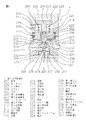
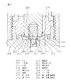
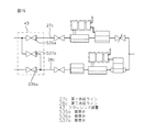
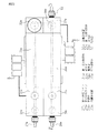
以下、本発明の実施の形態について図面に示す実施例を参照して説明するが、本発明が本実施例に限定されないことは言うまでもない。図1は本発明の流体混合装置の第一の実施例を模式的に示す構成図である。図2は流量計測器の縦断面図である。図3は第一流体制御弁の縦断面図である。図4は第二流体制御弁の縦断面図である。図5は本発明の流体混合装置の第二の実施例を模式的に示す構成図である。図6は開閉弁の縦断面図である。図7は本発明の流体混合装置の第三の実施例を模式的に示す構成図である。図8は絞り弁の縦断面図である。図9は図8の絞り弁が開状態を示す要部拡大図である。図10は図8の絞り弁が閉状態を示す要部拡大図である。図11は図8の絞り弁が半開状態を示す要部拡大図である。図12は本発明の流体混合装置の第四の実施例を模式的に示す構成図である。図13は本発明の流体混合装置の第五の実施例を模式的に示す構成図である。図14はマニホールド弁の断面図である。図15は本発明の流体混合装置の第六の実施例を模式的に示す構成図である。図16は本発明のフラッシング装置の流路を模式的に示す斜視図である。図17は図16のA−A線に沿う縦断面図である。図18は本発明の流体混合装置の第七の実施例を模式的に示す平面図である。図19は図18のB−B線に沿う断面図である。図20は本発明の流体混合装置の第八の実施例を模式的に示す平面図である。図21は図20のC−C線に沿う断面図である。図22は本発明の流体混合装置の第九の実施例を模式的に示す断面図である。図23は本発明の流体混合装置の第十の実施例の他の第一流体制御弁の縦断面図である。図24は図23に他の表示を追加した図23と同一の図である。図25は本発明の流体混合装置の第十一の実施例の他の第二流体制御弁の縦断面図である。図26は本発明の流体混合装置の第十二の実施例の他の第二流体制御弁の縦断面図である。図27は本発明の流体混合装置の第十三の実施例の他の第二流体制御弁の縦断面図である。図28は本発明の流体混合装置の第十四の実施例の他の圧力調整弁の縦断面図である。図29は本発明の流体混合装置の第十五の実施例の他の流量計測器の縦断面図である。図30は本発明の流体混合装置の第十六の実施例の他の流量計測器の縦断面図である。   Hereinafter, embodiments of the present invention will be described with reference to examples shown in the drawings. However, it is needless to say that the present invention is not limited to the examples. FIG. 1 is a block diagram schematically showing a first embodiment of the fluid mixing apparatus of the present invention. FIG. 2 is a longitudinal sectional view of the flow rate measuring device. FIG. 3 is a longitudinal sectional view of the first fluid control valve. FIG. 4 is a longitudinal sectional view of the second fluid control valve. FIG. 5 is a block diagram schematically showing a second embodiment of the fluid mixing apparatus of the present invention. FIG. 6 is a longitudinal sectional view of the on-off valve. FIG. 7 is a block diagram schematically showing a third embodiment of the fluid mixing apparatus of the present invention. FIG. 8 is a longitudinal sectional view of the throttle valve. FIG. 9 is an enlarged view of a main part showing the throttle valve of FIG. 8 in an open state. FIG. 10 is an enlarged view of a main part showing the throttle valve of FIG. 8 in a closed state. FIG. 11 is an enlarged view of a main part showing the throttle valve of FIG. 8 in a half-open state. FIG. 12 is a block diagram schematically showing a fourth embodiment of the fluid mixing apparatus of the present invention. FIG. 13 is a block diagram schematically showing a fifth embodiment of the fluid mixing apparatus of the present invention. FIG. 14 is a sectional view of the manifold valve. FIG. 15 is a block diagram schematically showing a sixth embodiment of the fluid mixing apparatus of the present invention. FIG. 16 is a perspective view schematically showing a flow path of the flushing device of the present invention. FIG. 17 is a longitudinal sectional view taken along line AA of FIG. FIG. 18 is a plan view schematically showing a seventh embodiment of the fluid mixing apparatus of the present invention. FIG. 19 is a sectional view taken along line BB in FIG. FIG. 20 is a plan view schematically showing an eighth embodiment of the fluid mixing apparatus of the present invention. 21 is a cross-sectional view taken along the line CC of FIG. FIG. 22 is a sectional view schematically showing a ninth embodiment of the fluid mixing apparatus of the present invention. FIG. 23 is a longitudinal sectional view of another first fluid control valve of the tenth embodiment of the fluid mixing apparatus of the present invention. FIG. 24 is the same as FIG. 23 with another display added to FIG. FIG. 25 is a longitudinal sectional view of another second fluid control valve of the eleventh embodiment of the fluid mixing apparatus of the present invention. FIG. 26 is a longitudinal sectional view of another second fluid control valve of the twelfth embodiment of the fluid mixing apparatus of the present invention. FIG. 27 is a longitudinal sectional view of another second fluid control valve of the thirteenth embodiment of the fluid mixing apparatus of the present invention. FIG. 28 is a longitudinal sectional view of another pressure regulating valve of the fourteenth embodiment of the fluid mixing apparatus of the present invention. FIG. 29 is a longitudinal sectional view of another flow rate measuring device according to the fifteenth embodiment of the fluid mixing apparatus of the present invention. FIG. 30 is a longitudinal sectional view of another flow rate measuring device according to the sixteenth embodiment of the fluid mixing apparatus of the present invention.

以下、図1乃至図4に基づいて本発明の第一の実施例である流体混合装置について説明する。   Hereinafter, a fluid mixing apparatus according to a first embodiment of the present invention will be described with reference to FIGS.

流体混合装置は二つの供給ライン、すなわち第一供給ライン1と第二供給ライン2から形成されている。第一供給ライン1は流量計測器3、第一流体制御弁4の順で接続され制御部5が設けられ、第二供給ライン2は流量計測器9、第二流体制御弁10の順で接続され制御部11が設けられている。第一、第二供給ライン1、2の最下流側には、該供給ライン1、2の合流部15が設けられている。その各々の構成は以下の通りである。   The fluid mixing device is formed from two supply lines, a first supply line 1 and a second supply line 2. The first supply line 1 is connected in the order of the flow rate measuring device 3 and the first fluid control valve 4, and a control unit 5 is provided. The second supply line 2 is connected in the order of the flow rate measuring device 9 and the second fluid control valve 10. A control unit 11 is provided. A merging portion 15 of the supply lines 1 and 2 is provided on the most downstream side of the first and second supply lines 1 and 2. Each configuration is as follows.

3、9は流体の流量を計測する超音波流量計である流量計測器である。流量計測器3、9は、入口流路371と、入口流路371から垂設された直線流路372と、直線流路372から垂設され入口流路371と同一方向に平行して設けられた出口流路373とを有し、入口、出口流路371、373の側壁の直線流路372の軸線と交わる位置に、超音波振動子374、375が互いに対向して配置されている。超音波振動子374、375はフッ素樹脂で覆われており、該振動子374、375から伸びた配線は後記制御部5、11の演算部6、12に繋がっている。なお、流量計測器3、9の超音波振動子374、375以外はPFA製である。   Reference numerals 3 and 9 denote flow rate measuring devices which are ultrasonic flow meters for measuring the flow rate of the fluid. The flow rate measuring devices 3 and 9 are provided in parallel with the inlet channel 371, the straight channel 372 suspended from the inlet channel 371, and the inlet channel 371 suspended from the straight channel 372. The ultrasonic transducers 374 and 375 are arranged opposite to each other at positions where the side walls of the inlet and outlet channels 371 and 373 intersect with the axis of the straight channel 372. The ultrasonic vibrators 374 and 375 are covered with a fluororesin, and wirings extending from the vibrators 374 and 375 are connected to calculation units 6 and 12 of the control units 5 and 11 described later. The ultrasonic transducers 374 and 375 of the flow rate measuring devices 3 and 9 are made of PFA.

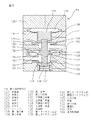
4は操作圧に応じて流体圧力を制御する第一流体制御弁である。第一流体制御弁4は本体201、ボンネット202、バネ受け203、ピストン204、バネ205、第一弁機構体206、第二弁機構体207、ベースプレート208で形成される。   A first fluid control valve 4 controls the fluid pressure according to the operation pressure. The first fluid control valve 4 includes a main body 201, a bonnet 202, a spring receiver 203, a piston 204, a spring 205, a first valve mechanism 206, a second valve mechanism 207, and a base plate 208.

201はPTFE製の本体であり、下部中央に底部まで開放して設けられた第二の空隙209と、上部に上面開放して設けられた第二の空隙209の径よりも大きい径を持つ第一の空隙210を有し、側面には第二の空隙209と連通している入口流路211と、入口流路211と対向する面に第一の空隙210と連通している出口流路212と、さらに、第一の空隙210と第二の空隙209とを連通し第一の空隙210の径よりも小さい径を有する連通孔213とが設けられている。第二の空隙209の上面部は弁座214とされている。   Reference numeral 201 denotes a PTFE main body having a diameter larger than the diameter of the second gap 209 provided open to the bottom at the center of the lower part and the second gap 209 provided open at the top at the upper part. The inlet channel 211 having one gap 210 and communicating with the second gap 209 on the side surface, and the outlet channel 212 communicating with the first gap 210 on the surface facing the inlet channel 211. In addition, a communication hole 213 that communicates the first gap 210 and the second gap 209 and has a diameter smaller than the diameter of the first gap 210 is provided. The upper surface portion of the second gap 209 is a valve seat 214.

202はPVDF製のボンネットであり、内部に円筒状の空隙215と下端内周面に空隙215より拡径された段差部216が設けられ、側面には空隙215内部に圧縮空気を供給するために空隙215と外部とを連通する給気孔217および給気孔217より導入された圧縮空気を微量に排出するための微孔の排出孔218が設けられている。なお、排出孔218は圧縮空気の供給において必要ない場合は設けなくてもかまわない。   202 is a PVDF bonnet, in which a cylindrical gap 215 and a stepped portion 216 having a diameter larger than that of the gap 215 are provided on the inner peripheral surface of the lower end, and in order to supply compressed air to the inside of the gap 215 on the side surface. An air supply hole 217 that communicates between the air gap 215 and the outside, and a microhole discharge hole 218 for discharging a small amount of compressed air introduced from the air supply hole 217 are provided. Note that the discharge hole 218 may be omitted if it is not necessary for supplying compressed air.

203はPVDF製で平面円形状のバネ受けであり、中央部に貫通孔219を有し、略上半分がボンネット202の段差部216に嵌挿されている。バネ受け203の側面部には環状溝220が設けられ、O−リング221を装着することによりボンネット202から外部への圧縮空気の流出を防いでいる。   203 is a flat circular spring receiver made of PVDF, has a through hole 219 in the center, and is fitted into the stepped portion 216 of the bonnet 202 at substantially the upper half. An annular groove 220 is provided on the side surface of the spring receiver 203, and an O-ring 221 is attached to prevent the compressed air from flowing out from the bonnet 202 to the outside.

204はPVDF製のピストンであり、上部に円盤状の鍔部222と、鍔部222の中央下部より円柱状に突出して設けられたピストン軸223と、ピストン軸223の下端に設けられた雌ネジ部からなる第一接合部224を有する。ピストン軸223はバネ受け203の貫通孔219より小径に設けられており、第一接合部224は後記第一弁機構体206の第二接合部229と螺合により接合されている。   Reference numeral 204 denotes a PVDF piston, which has a disk-shaped flange 222 at the top, a piston shaft 223 that protrudes in a cylindrical shape from the center lower portion of the flange 222, and a female screw that is provided at the lower end of the piston shaft 223 The first joint 224 is formed of a portion. The piston shaft 223 is provided with a smaller diameter than the through hole 219 of the spring receiver 203, and the first joint portion 224 is joined to the second joint portion 229 of the first valve mechanism 206 described later by screwing.

205はSUS製のバネであり、ピストン204の鍔部222下端面とバネ受け203の上端面とで挟持されている。ピストン204の上下動にともなってバネ205も伸縮するが、そのときの荷重の変化が少ないよう、自由長の長いものが好適に使用される。   Reference numeral 205 denotes a SUS spring, which is sandwiched between the lower end surface of the flange portion 222 of the piston 204 and the upper end surface of the spring receiver 203. The spring 205 also expands and contracts as the piston 204 moves up and down, but a long free length is preferably used so that the change in load at that time is small.

206はPTFE製の第一弁機構体であり、外周縁部より上方に突出して設けられた筒状部225を有した膜部226と肉厚部を中央部に有する第一ダイヤフラム227と、第一ダイヤフラム227の中央上面より突出して設けられた軸部228の上端部に設けられた小径の雄ネジからなる第二接合部229、および同中央下面より突出して設けられ下端部に形成された雌ネジ部からなる後記第二弁機構体207の第四接合部234と螺合される第三接合部230を有する。第一ダイヤフラム227の筒状部225は、本体201とバネ受け203との間で挟持固定されることで、第一ダイヤフラム227下面より形成される第一の弁室231が密封して形成されている。また、第一ダイヤフラム227上面、ボンネット202の空隙215はO−リング221を介して密封されており、ボンネット202の給気孔217より供給される圧縮空気が充満している気室を形成している。   Reference numeral 206 denotes a PTFE first valve mechanism, which includes a membrane portion 226 having a cylindrical portion 225 provided so as to protrude upward from the outer peripheral edge portion, a first diaphragm 227 having a thick portion at the center portion, A second joint portion 229 made of a small-diameter male screw provided at the upper end portion of the shaft portion 228 provided to protrude from the center upper surface of the diaphragm 227, and a female formed at the lower end portion protruding from the center lower surface. It has the 3rd junction part 230 screwed together with the 4th junction part 234 of the postscript 2nd valve mechanism body 207 which consists of a thread part. The cylindrical portion 225 of the first diaphragm 227 is sandwiched and fixed between the main body 201 and the spring receiver 203 so that the first valve chamber 231 formed from the lower surface of the first diaphragm 227 is hermetically formed. Yes. The upper surface of the first diaphragm 227 and the gap 215 of the bonnet 202 are sealed through an O-ring 221 to form an air chamber filled with compressed air supplied from the air supply hole 217 of the bonnet 202. .

207はPTFE製の第二弁機構体であり、本体201の第二の空隙209内部に配設され連通孔213より大径に設けられた弁体232と、弁体232上端面から突出して設けられた軸部233と、その上端に設けられた第三接合部230と螺合により接合固定される雄ネジ部からなる第四接合部234と、弁体232下端面より突出して設けられたロッド235と、ロッド235下端面より径方向に延出して設けられ周縁部より下方に突出して設けられた筒状突部236を有する第二ダイヤフラム237とから構成されている。第二ダイヤフラム237の筒状突部236は後記ベースプレート208の突出部239と本体201との間で挟持されることにより、本体201の第二の空隙209と第二ダイヤフラム237とで形成される第二の弁室238を密閉している。   Reference numeral 207 denotes a PTFE second valve mechanism body, which is provided inside the second gap 209 of the main body 201 and provided with a larger diameter than the communication hole 213, and protrudes from the upper end surface of the valve body 232. A shaft portion 233, a fourth joint portion 234 comprising a male screw portion that is joined and fixed to the third joint portion 230 provided at the upper end thereof, and a rod provided so as to protrude from the lower end surface of the valve body 232 235, and a second diaphragm 237 having a cylindrical protrusion 236 that extends in the radial direction from the lower end surface of the rod 235 and protrudes downward from the peripheral edge. The cylindrical protrusion 236 of the second diaphragm 237 is sandwiched between a protrusion 239 of the base plate 208 and the main body 201, which will be described later, so that a second gap 209 of the main body 201 and the second diaphragm 237 are formed. The second valve chamber 238 is sealed.

208はPVDF製のベースプレートであり、上部中央に第二弁機構体207の第二ダイヤフラム237の筒状突部236を本体201との間で挟持固定する突出部239を有し、突出部239の上端部に切欠凹部240が設けられると共に、側面に切欠凹部240に連通する呼吸孔241が設けられており、ボンネット202との間で本体201を通しボルト、ナット(図示せず)にて挟持固定している。なお、本実施例ではバネ205がボンネット202の空隙215内に設けてピストン204、第一弁機構体206、第二弁機構体207を上方へ付勢するような構成であるが、バネ205をベースプレート208の切欠凹部240に設けてピストン204、第一弁機構体206、第二弁機構体207を上方へ付勢するような構成にしても良い。   Reference numeral 208 denotes a PVDF base plate having a protruding portion 239 for holding and fixing the cylindrical protruding portion 236 of the second diaphragm 237 of the second valve mechanism 207 between the main body 201 at the upper center. A notch recess 240 is provided at the upper end, and a breathing hole 241 communicating with the notch recess 240 is provided on the side surface. The main body 201 is passed between the bonnet 202 and fixed with bolts and nuts (not shown). is doing. In this embodiment, the spring 205 is provided in the gap 215 of the bonnet 202 to urge the piston 204, the first valve mechanism 206, and the second valve mechanism 207 upward. A configuration may be adopted in which the piston 204, the first valve mechanism 206, and the second valve mechanism 207 are urged upward by being provided in the notch recess 240 of the base plate 208.

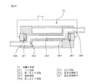
10は操作圧に応じて流路の開口面積を変化させることにより流体の流量を制御する第二流体制御弁(空気式ニードル弁)である。第二流体制御弁10は本体301、シリンダー302、ボンネット303、第一ダイヤフラム304、弁体305、第二ダイヤフラム306、ロッド307、ダイヤフラム押え308、スプリング309で構成される。   Reference numeral 10 denotes a second fluid control valve (pneumatic needle valve) that controls the flow rate of the fluid by changing the opening area of the flow path in accordance with the operation pressure. The second fluid control valve 10 includes a main body 301, a cylinder 302, a bonnet 303, a first diaphragm 304, a valve body 305, a second diaphragm 306, a rod 307, a diaphragm presser 308, and a spring 309.

301はPTFE製の本体であり、上部に円筒状の弁室310が設けられており、その弁室310に連通して入口流路311及び出口流路312が各々下部に設けられている。弁室底部中央には出口流路312に繋がる開口部313が、開口部313の周辺部には入口流路311に繋がる開口部314が設けられている。開口部314の横断面形状は円形であるが、流量を広範囲に亘って制御するために開口部313を大きくした場合は、弁室底部中央に設けられた開口部313を中心とした周辺部に略三日月状に形成されることが望ましい。本体301の上面には第一ダイヤフラム304のシール部が嵌合される環状溝330が設けられている。   A main body 301 made of PTFE is provided with a cylindrical valve chamber 310 in the upper part, and an inlet channel 311 and an outlet channel 312 are provided in the lower part in communication with the valve chamber 310. An opening 313 connected to the outlet channel 312 is provided at the center of the bottom of the valve chamber, and an opening 314 connected to the inlet channel 311 is provided around the opening 313. The cross-sectional shape of the opening 314 is circular, but when the opening 313 is enlarged in order to control the flow rate over a wide range, the opening 314 is formed in the peripheral part centered on the opening 313 provided at the center of the bottom of the valve chamber. It is desirable to form a substantially crescent shape. An annular groove 330 into which the seal portion of the first diaphragm 304 is fitted is provided on the upper surface of the main body 301.

302はPVC製のシリンダーであり、底部中央に貫通孔315と底部内面に段差部335を有し、側面に呼吸口316が設けられている。シリンダー302は、本体1と第一ダイヤフラム304の周縁部を挟持固定し、ボンネット303と第二ダイヤフラム306の周縁部を挟持固定している。シリンダー302の側面に設けられた呼吸口316は、流体がガスとなって第一ダイヤフラム304を透過した場合に、そのガスを排出するために設けられている。   Reference numeral 302 denotes a PVC cylinder, which has a through hole 315 at the center of the bottom, a step 335 on the inner surface of the bottom, and a breathing port 316 on the side. The cylinder 302 sandwiches and fixes the peripheral portions of the main body 1 and the first diaphragm 304 and sandwiches and fixes the peripheral portions of the bonnet 303 and the second diaphragm 306. The breathing port 316 provided on the side surface of the cylinder 302 is provided for discharging the gas when the fluid passes through the first diaphragm 304 as a gas.

303はPVC製のボンネットであり、上部に圧縮空気を導入する作動流体連通口317及び排気口318が設けられている。本実施例では作動流体連通口317はボンネット303の上部に設けられているが、側面に設けても良い。なお、排気口318は圧縮空気の供給において必要ない場合は設けなくてもかまわない。また周側部の下部には第二ダイヤフラム306のシール部327が嵌合される環状溝331が設けられている。以上説明した本体301、シリンダー302およびボンネット303はボルト、ナット(図示しない)によって一体的に固定されている。   303 is a bonnet made of PVC, and is provided with a working fluid communication port 317 and an exhaust port 318 for introducing compressed air at the top. In this embodiment, the working fluid communication port 317 is provided in the upper part of the bonnet 303, but may be provided in the side surface. Note that the exhaust port 318 may be omitted if it is not necessary for supplying compressed air. Further, an annular groove 331 into which the seal portion 327 of the second diaphragm 306 is fitted is provided at the lower portion of the peripheral side portion. The main body 301, cylinder 302, and bonnet 303 described above are integrally fixed by bolts and nuts (not shown).

304はPTFE製の第一ダイヤフラムであり、肩部319を中心に肩部319の上の位置にロッド307に嵌合固定される取り付け部320が、また、下の位置には弁体305が固定される接合部332が一体的にかつ突出して設けられており、また肩部319から径方向に延出した部分には薄膜部321と、薄膜部321に続く厚肉部322および厚肉部322の周縁部にシール部323が設けられており、これらは一体的に形成されている。薄膜部321の膜厚は厚肉部322の厚さの1/10程度にされている。ロッド307と取り付け部320の固定の方法は嵌合だけでなく螺合でも接着でもよい。接合部332と弁体305の固定は螺合が好ましい。第一ダイヤフラム304の外周縁部に位置するシール部323は軸線方向に断面L字状に形成されており、O−リング336を介して本体301の環状溝330に嵌合され、シリンダー302の底部に設けられた環状突部328に押圧されて挟持固定されている。   Reference numeral 304 denotes a PTFE first diaphragm, which has a mounting portion 320 fitted and fixed to the rod 307 at a position above the shoulder 319 with the shoulder 319 as the center, and a valve body 305 at the lower position. The joint portion 332 is provided integrally and projecting, and a thin film portion 321 and a thick portion 322 and a thick portion 322 following the thin film portion 321 are provided in a portion extending in the radial direction from the shoulder portion 319. A seal portion 323 is provided at the peripheral edge of the two, and these are integrally formed. The thickness of the thin film portion 321 is set to about 1/10 of the thickness of the thick portion 322. The method of fixing the rod 307 and the attachment portion 320 may be not only fitting but also screwing or bonding. The joint 332 and the valve body 305 are preferably screwed together. The seal portion 323 located at the outer peripheral edge of the first diaphragm 304 is formed in an L-shaped cross section in the axial direction, and is fitted into the annular groove 330 of the main body 301 via the O-ring 336, and the bottom of the cylinder 302 Is pressed and fixed by an annular protrusion 328 provided on the surface.

305はPTFE製の弁体であり、第一ダイヤフラム306の下部に設けられた接合部332に螺合固定されている。弁体305は本実施例のような形状に限らず所望の流量特性に応じて、球状弁体や円錐形状弁体でも良い。さらには摺動抵抗を極力少なくした状態で全閉を行う為には外周リブ付き弁体が好適に用いられる。   Reference numeral 305 denotes a PTFE valve body, which is screwed and fixed to a joint portion 332 provided at a lower portion of the first diaphragm 306. The valve body 305 is not limited to the shape as in the present embodiment, but may be a spherical valve body or a conical valve body in accordance with a desired flow rate characteristic. Further, a valve body with an outer peripheral rib is preferably used in order to perform full closure with the sliding resistance as low as possible.

306はエチレンプロピレンジエン共重合体(以下、EPDMと記す)製の第二ダイヤフラムであり、中央穴324を有し、その周辺の厚肉部325、厚肉部の上部には環状突部328、厚肉部325から径方向に延出した薄膜部326および薄膜部326の周縁部に設けられたシール部327が一体的に形成され、底部に第一ダイヤフラム304の取り付け部320が固定されているロッド307の上部に位置する肩部329にダイヤフラム押え308により中央穴324を貫通して挟持固定されている。本実施例では材質がEPDM製を用いているが、フッ素系のゴムまたはPTFE製でも良い。   306 is a second diaphragm made of an ethylene propylene diene copolymer (hereinafter referred to as EPDM), has a central hole 324, a thick portion 325 in the periphery thereof, an annular protrusion 328 on the upper portion of the thick portion, The thin film portion 326 extending in the radial direction from the thick wall portion 325 and the seal portion 327 provided at the peripheral edge of the thin film portion 326 are integrally formed, and the attachment portion 320 of the first diaphragm 304 is fixed to the bottom portion. The shoulder 329 located at the upper part of the rod 307 is sandwiched and fixed through the center hole 324 by the diaphragm presser 308. In this embodiment, the material used is EPDM, but fluorine-based rubber or PTFE may be used.

307はPVC製のロッドであり、上部には拡径された肩部329が設けられている。肩部329の中央にはダイヤフラム押え308の接合部334が螺合され、第二ダイヤフラム306を挟持固定している。下方部はシリンダー302底部の貫通孔315内に遊嵌状態に配置され、下端部には第一ダイヤフラム304の取り付け部320が固定されている。また、ロッド307の肩部329の下面とシリンダー302の段差部335との間にはスプリング309が嵌合されている。   Reference numeral 307 denotes a PVC rod, and a shoulder 329 having an enlarged diameter is provided at the top. A joint portion 334 of a diaphragm presser 308 is screwed into the center of the shoulder portion 329, and the second diaphragm 306 is clamped and fixed. The lower part is arranged in a loosely fitted state in the through hole 315 at the bottom of the cylinder 302, and the attachment part 320 of the first diaphragm 304 is fixed to the lower end part. A spring 309 is fitted between the lower surface of the shoulder portion 329 of the rod 307 and the step portion 335 of the cylinder 302.

308はPVC製のダイヤフラム押えであり、下面中央にはロッド307と螺合にて接続される接合部334が設けられている。また、下面には第二ダイヤフラム306の環状突部328と嵌合される環状溝333が設けられている。   Reference numeral 308 denotes a PVC diaphragm presser, and a joint portion 334 connected to the rod 307 by screwing is provided at the center of the lower surface. Further, an annular groove 333 is provided on the lower surface to be fitted with the annular protrusion 328 of the second diaphragm 306.

309はSUS製のスプリングであり、ロッド307の肩部329の下面とシリンダー302の段差部335との間に径方向への移動が阻止された状態で嵌合され支承されている。また、肩部329の下面を常に上方へ付勢している。スプリング309の全表面はフッ素系樹脂で被覆されている。尚、スプリング309は第二流体制御弁10の口径や使用圧力範囲によってバネ定数を変えて適宜使用でき、複数本使用してもよい。   Reference numeral 309 denotes a SUS spring, which is fitted and supported between the lower surface of the shoulder portion 329 of the rod 307 and the stepped portion 335 of the cylinder 302 in a state where movement in the radial direction is prevented. Further, the lower surface of the shoulder portion 329 is always urged upward. The entire surface of the spring 309 is covered with a fluorine resin. The spring 309 can be used as appropriate by changing the spring constant depending on the diameter of the second fluid control valve 10 and the operating pressure range, and a plurality of springs 309 may be used.

5、11は制御部である。制御部5、11は前記流量計測器3、9から出力された信号から流量を演算する演算部6、12と、フィードバック制御を行なうコントロール部7、13を有している。演算部6、12には、送信側の超音波振動子374に一定周期の超音波振動を出力する発信回路と、受信側の超音波振動子375からの超音波振動を受信する受信回路と、各超音波振動の伝搬時間を比較する比較回路と、比較回路から出力された伝搬時間差から流量を演算する演算回路とを備えている。コントロール部7、13には、演算部6、12から出力された流量に対して設定された流量になるように後記電空変換器8、14の操作圧を制御する制御回路を有している。なお、本実施例では制御部5、11は別の場所で集中コントロールを行なうために流体混合装置と別体で設けられた構成であるが、流体混合装置と一体的に設けても良い。   Reference numerals 5 and 11 denote control units. The control units 5 and 11 have calculation units 6 and 12 for calculating a flow rate from signals output from the flow rate measuring devices 3 and 9, and control units 7 and 13 for performing feedback control. The calculation units 6 and 12 include a transmission circuit that outputs ultrasonic vibration of a fixed period to the ultrasonic transducer 374 on the transmission side, a reception circuit that receives ultrasonic vibration from the ultrasonic transducer 375 on the reception side, A comparison circuit that compares the propagation times of the ultrasonic vibrations and an arithmetic circuit that calculates a flow rate from the propagation time difference output from the comparison circuit are provided. The control units 7 and 13 have a control circuit that controls the operation pressure of the electropneumatic converters 8 and 14 to be described later so that the flow rate is set to the flow rate output from the calculation units 6 and 12. . In this embodiment, the control units 5 and 11 are provided separately from the fluid mixing device in order to perform centralized control in another place, but may be provided integrally with the fluid mixing device.

8、14は制御部5、11内に配置されている圧縮空気の操作圧を調整する電空変換器である。電空変換器8、14は操作圧を比例的に調整するために電気的に駆動する電磁弁から構成され、前記制御部5、11からの制御信号に応じて流体制御弁4、10の操作圧を調整する。なお、電空変換器8、14は、制御部5、11内に配置せずに別体で配置してもかまわない。   8 and 14 are electropneumatic converters that adjust the operating pressure of the compressed air disposed in the control units 5 and 11. The electropneumatic converters 8 and 14 are composed of electromagnetic valves that are electrically driven to adjust the operation pressure proportionally, and the operation of the fluid control valves 4 and 10 according to the control signals from the control units 5 and 11. Adjust pressure. Note that the electropneumatic converters 8 and 14 may be disposed separately from the control units 5 and 11 without being disposed therein.

次に、本発明の第一の実施例である流体混合装置の作動について説明する。   Next, the operation of the fluid mixing apparatus according to the first embodiment of the present invention will be described.

ここでは第一供給ライン1に純水を流入させ、第二供給ライン2にフッ化水素酸を流入させ、純水:フッ化水素酸=10:1になるように混合する。まず、第一供給ライン1に流入した純水は、流量計測器3で流量が計測され、計測した流量に応じて制御部5で第一流体制御弁4の操作圧を制御し、第一流体制御弁4で第一供給ライン1の最下流の流量が設定流量(第一供給ライン1と第二供給ライン2の流量の比率が10:1であり、混合流体が設定された流量になるための流量)になるように制御される。また第二供給ライン2に流入したフッ化水素酸は、流量計測器9で流量が計測され、計測した流量に応じて制御部11で第二流体制御弁10の操作圧を制御し、第二流体制御弁10で第二供給ライン2の最下流の流量が設定流量(第一供給ライン1と第二供給ライン2の流量の比率が10:1であり、混合流体が設定された流量になるための流量)になるように制御される。第一、第二供給ライン1、2で流量が制御された純水とフッ化水素酸は合流部15で合流して混合される。混合された混合流体(希フッ酸)は基板の洗浄装置の処理工程で使用され、洗浄装置内で混合流体により基板の酸化膜除去が行なわれる。   Here, pure water is introduced into the first supply line 1, and hydrofluoric acid is introduced into the second supply line 2, and mixing is performed so that pure water: hydrofluoric acid = 10: 1. First, the flow rate of the pure water flowing into the first supply line 1 is measured by the flow rate measuring device 3, and the operation pressure of the first fluid control valve 4 is controlled by the control unit 5 according to the measured flow rate. In the control valve 4, the most downstream flow rate of the first supply line 1 is the set flow rate (the ratio of the flow rates of the first supply line 1 and the second supply line 2 is 10: 1, and the mixed fluid becomes the set flow rate. Of the flow rate). The flow rate of the hydrofluoric acid flowing into the second supply line 2 is measured by the flow rate measuring device 9, and the operation pressure of the second fluid control valve 10 is controlled by the control unit 11 according to the measured flow rate, The most downstream flow rate of the second supply line 2 in the fluid control valve 10 is a set flow rate (the ratio of the flow rates of the first supply line 1 and the second supply line 2 is 10: 1, and the mixed fluid is set to a set flow rate. For the flow rate). Pure water and hydrofluoric acid, the flow rates of which are controlled by the first and second supply lines 1 and 2, are merged and mixed in the merge section 15. The mixed fluid (dilute hydrofluoric acid) mixed is used in the processing step of the substrate cleaning apparatus, and the oxide film of the substrate is removed by the mixed fluid in the cleaning apparatus.

次に、流量計測器3、9、第一流体制御弁4、第二流体制御弁10、制御部5、11のそれぞれの作動について、図1乃至図3を参照しながら説明する。   Next, operations of the flow rate measuring devices 3 and 9, the first fluid control valve 4, the second fluid control valve 10, and the control units 5 and 11 will be described with reference to FIGS.

流量計測器3、9に流入した純水又はフッ化水素酸は、直線流路372で流量が計測される。純水又はフッ化水素酸の流れに対して上流側に位置する超音波振動子374から下流側に位置する超音波振動子375に向かって超音波振動を伝播させる。超音波振動子375で受信された超音波振動は電気信号に変換され、制御部5、11の演算部6、12へ出力される。超音波振動が上流側の超音波振動子374から下流側の超音波振動子375へ伝播して受信されると、瞬時に演算部6、12内で送受信が切換えられて、下流側に位置する超音波振動子375から上流側に位置する超音波振動子374に向かって超音波振動を伝播させる。超音波振動子374で受信された超音波振動は、電気信号に変換され、制御部5、11内の演算部6、12へ出力される。このとき、超音波振動は直線流路372内の流体の流れに逆らって伝播していくので、上流側から下流側へ超音波振動を伝播させるときに比べて流体中での超音波振動の伝播速度が遅れ、伝播時間が長くなる。出力された相互の電気信号は演算部6、12内で伝播時間が各々計測され、伝播時間差から流量が演算される。演算部6、12で演算された流量は電気信号に変換されてコントロール部7、13に出力される。   The flow rate of pure water or hydrofluoric acid that has flowed into the flow rate measuring instruments 3 and 9 is measured in the straight flow path 372. The ultrasonic vibration is propagated from the ultrasonic vibrator 374 located on the upstream side to the ultrasonic vibrator 375 located on the downstream side with respect to the flow of pure water or hydrofluoric acid. The ultrasonic vibration received by the ultrasonic transducer 375 is converted into an electric signal and output to the calculation units 6 and 12 of the control units 5 and 11. When the ultrasonic vibration propagates from the upstream ultrasonic transducer 374 to the downstream ultrasonic transducer 375 and is received, transmission / reception is instantaneously switched in the arithmetic units 6 and 12 and positioned downstream. Ultrasonic vibration is propagated from the ultrasonic transducer 375 toward the ultrasonic transducer 374 located upstream. The ultrasonic vibration received by the ultrasonic transducer 374 is converted into an electric signal and output to the calculation units 6 and 12 in the control units 5 and 11. At this time, since the ultrasonic vibration propagates against the flow of the fluid in the straight flow path 372, the propagation of the ultrasonic vibration in the fluid is greater than when the ultrasonic vibration is propagated from the upstream side to the downstream side. The speed is delayed and the propagation time is increased. The output electrical signals are measured for propagation times in the calculation units 6 and 12, and the flow rate is calculated from the difference in propagation times. The flow rates calculated by the calculation units 6 and 12 are converted into electrical signals and output to the control units 7 and 13.

次に流量計測器3、9を通過した純水又はフッ化水素酸は流体制御弁4、10に流入する。制御部5、11のコントロール部7、13では、任意の設定流量に対して、リアルタイムに計測された流量との偏差から、偏差をゼロにするように信号を電空変換器8、14に出力し、電空変換器8、14はそれに応じた操作圧を流体制御弁4、10に供給し駆動させる。流体制御弁4、10から流出する純水又はフッ化水素酸の流量は、流体制御弁4、10で調圧された圧力と、流体制御弁4、10以降の圧力損失との関係で決定されており、調圧された圧力が高いほど流量は大きくなり、逆に圧力が低いほど流量は小さくなる。このため純水又はフッ化水素酸は、流量を設定流量で一定値となるように、つまり設定流量と計測された流量の偏差がゼロに収束されるように流体制御弁4、10で制御される。   Next, the pure water or hydrofluoric acid that has passed through the flow rate measuring devices 3 and 9 flows into the fluid control valves 4 and 10. The control units 7 and 13 of the control units 5 and 11 output a signal to the electropneumatic converters 8 and 14 so that the deviation is zero from the deviation from the flow rate measured in real time with respect to any set flow rate. Then, the electropneumatic converters 8 and 14 supply the operation pressure corresponding thereto to the fluid control valves 4 and 10 to drive them. The flow rate of pure water or hydrofluoric acid flowing out from the fluid control valves 4 and 10 is determined by the relationship between the pressure adjusted by the fluid control valves 4 and 10 and the pressure loss after the fluid control valves 4 and 10. The higher the regulated pressure, the larger the flow rate. Conversely, the lower the pressure, the smaller the flow rate. Therefore, pure water or hydrofluoric acid is controlled by the fluid control valves 4 and 10 so that the flow rate becomes a constant value at the set flow rate, that is, the deviation between the set flow rate and the measured flow rate is converged to zero. The

ここで、電空変換器8から供給される操作圧に対する第一流体制御弁4の流体(純水又はフッ化水素酸)に対する作動について説明する(図3参照)。   Here, the action | operation with respect to the fluid (pure water or hydrofluoric acid) of the 1st fluid control valve 4 with respect to the operation pressure supplied from the electropneumatic converter 8 is demonstrated (refer FIG. 3).

第二弁機構体207の弁体232は、ピストン204の鍔部222とバネ受け203とに挟持されているバネ205の反発力と、第一弁機構体206の第一ダイヤフラム227下面の流体圧力により上方に付勢する力が働き、第一ダイヤフラム227上面の操作圧の圧力により下方に付勢する力が働いている。さらに厳密には、弁体232下面と第二弁機構体207の第二ダイヤフラム237上面が流体圧力を受けているが、それらの受圧面積はほぼ同等とされているため力はほぼ相殺されている。したがって、第二弁機構体207の弁体232は、前述の3つの力が釣り合う位置にて静止していることとなる。   The valve body 232 of the second valve mechanism 207 includes the repulsive force of the spring 205 sandwiched between the flange 222 of the piston 204 and the spring receiver 203, and the fluid pressure on the lower surface of the first diaphragm 227 of the first valve mechanism 206. Due to this, a force for urging upward acts, and a force for urging downward by the operating pressure on the upper surface of the first diaphragm 227 is exerted. More precisely, although the lower surface of the valve body 232 and the upper surface of the second diaphragm 237 of the second valve mechanism 207 are subjected to fluid pressure, their pressure receiving areas are substantially equal, so the force is almost offset. . Therefore, the valve body 232 of the second valve mechanism 207 is stationary at a position where the above-described three forces are balanced.

電空変換機8から供給される操作圧力を増加させると第一ダイヤフラム227を押し下げる力が増加することにより、第二弁機構体207の弁体232と弁座214との間で形成される流体制御部242の開口面積が増加するため、第一の弁室231の圧力を増加させることができる。逆に、操作圧力を減少させると流体制御部242の開口面積は減少し圧力も減少する。そのため、操作圧力を調整することで任意の圧力に設定することができる。   When the operating pressure supplied from the electropneumatic converter 8 is increased, the force that pushes down the first diaphragm 227 increases, so that the fluid formed between the valve body 232 of the second valve mechanism 207 and the valve seat 214. Since the opening area of the control unit 242 increases, the pressure in the first valve chamber 231 can be increased. Conversely, when the operating pressure is decreased, the opening area of the fluid control unit 242 is decreased and the pressure is also decreased. Therefore, an arbitrary pressure can be set by adjusting the operation pressure.

この状態で、上流側の流体圧力が増加した場合、瞬間的に第一の弁室231内の圧力も増加する。すると、第一ダイヤフラム227の上面が操作圧による圧縮空気から受ける力より、第一ダイヤフラム227の下面が流体から受ける力のほうが大きくなり、第一ダイヤフラム227は上方へと移動する。それにともなって、弁体232の位置も上方へ移動するため、弁座214との間で形成される流体制御部242の開口面積が減少し、第一の弁室231内の圧力を減少させる。最終的に、弁体232の位置が前記3つの力が釣り合う位置まで移動し静止する。このときバネ205の荷重が大きく変わらなければ、空隙215内部の圧力、つまり、第一ダイヤフラム227上面が受ける力は一定であるため、第一ダイヤフラム227下面が受ける圧力はほぼ一定となる。したがって、第一ダイヤフラム227下面の流体圧力、すなわち、第一の弁室231内の圧力は、上流側の圧力が増加する前とほぼもとの圧力と同じになっている。   In this state, when the upstream fluid pressure increases, the pressure in the first valve chamber 231 increases instantaneously. Then, the force that the lower surface of the first diaphragm 227 receives from the fluid is greater than the force that the upper surface of the first diaphragm 227 receives from the compressed air due to the operating pressure, and the first diaphragm 227 moves upward. Accordingly, the position of the valve body 232 also moves upward, so that the opening area of the fluid control unit 242 formed between the valve seat 214 and the pressure in the first valve chamber 231 is reduced. Eventually, the position of the valve body 232 moves to a position where the three forces are balanced and stops. At this time, if the load of the spring 205 does not change significantly, the pressure inside the gap 215, that is, the force received by the upper surface of the first diaphragm 227 is constant, so that the pressure received by the lower surface of the first diaphragm 227 is substantially constant. Therefore, the fluid pressure on the lower surface of the first diaphragm 227, that is, the pressure in the first valve chamber 231 is almost the same as the original pressure before the upstream pressure increases.

上流側の流体圧力が減少した場合、瞬間的に第一の弁室231内の圧力も減少する。すると、第一ダイヤフラム227の上面が操作圧による圧縮空気から受ける力より、第一ダイヤフラム227の下面が流体から受ける力のほうが小さくなり、第一ダイヤフラム227は下方へと移動する。それにともなって、弁体232の位置も下方へ移動するため、弁座214との間で形成される流体制御部242の開口面積が増加し、第一の弁室231の流体圧力を増加させる。最終的に、弁体232の位置が前記3つの力が釣り合う位置まで移動し静止する。したがって、上流側圧力が増加した場合と同様に、第一の弁室231内の流体圧力はほぼもとの圧力と同じになっている。   When the upstream fluid pressure decreases, the pressure in the first valve chamber 231 also decreases instantaneously. Then, the force that the lower surface of the first diaphragm 227 receives from the fluid is smaller than the force that the upper surface of the first diaphragm 227 receives from the compressed air due to the operating pressure, and the first diaphragm 227 moves downward. Accordingly, the position of the valve body 232 also moves downward, so that the opening area of the fluid control unit 242 formed between the valve seat 214 and the fluid pressure in the first valve chamber 231 is increased. Eventually, the position of the valve body 232 moves to a position where the three forces are balanced and stops. Accordingly, the fluid pressure in the first valve chamber 231 is substantially the same as the original pressure, as in the case where the upstream pressure has increased.

これにより、第一流体制御弁4は上記構成によりコンパクトで安定した流体(純水又はフッ化水素酸)の圧力制御が得られ、一定の流体圧力になることにより流体流量も一定となる。また、供給ラインに流入する流体(純水又はフッ化水素酸)の上流側圧力が変動しても第一流体制御弁4の作動により流量は自立的に一定に保たれるためポンプの脈動など瞬間的な圧力変動が発生しても安定して流量を制御することができる。   Thereby, the first fluid control valve 4 can obtain a compact and stable pressure control of the fluid (pure water or hydrofluoric acid) by the above-described configuration, and the fluid flow rate becomes constant when the fluid pressure becomes constant. Further, even if the upstream pressure of the fluid (pure water or hydrofluoric acid) flowing into the supply line fluctuates, the flow rate is independently maintained constant by the operation of the first fluid control valve 4, so that the pump pulsation, etc. Even if instantaneous pressure fluctuations occur, the flow rate can be controlled stably.

ここで、電空変換器14から供給される操作圧に対する第二流体制御弁10の流体(純水又はフッ化水素酸)に対する作動について説明する。   Here, the action | operation with respect to the fluid (pure water or hydrofluoric acid) of the 2nd fluid control valve 10 with respect to the operating pressure supplied from the electropneumatic converter 14 is demonstrated.

第二流体制御弁10は、ボンネット303の上部に設けられた作動流体連通口317から供給される圧縮空気がゼロの状態、すなわち開状態のとき、流体の流量が最大となる。この時、弁体305はシリンダー302の段差部335とロッド307の肩部329の下面との間に嵌合されたスプリング309の付勢力により、ロッド307の上部に接合されているダイヤフラム押え308の上部が、ボンネット302の底面に接する位置で静止している。   The second fluid control valve 10 has a maximum fluid flow rate when the compressed air supplied from the working fluid communication port 317 provided in the upper part of the bonnet 303 is zero, that is, in the open state. At this time, the valve body 305 has a diaphragm retainer 308 joined to the upper portion of the rod 307 by the urging force of the spring 309 fitted between the step portion 335 of the cylinder 302 and the lower surface of the shoulder portion 329 of the rod 307. The upper part is stationary at a position in contact with the bottom surface of the bonnet 302.

この状態において、作動流体連通口317から供給される圧縮空気の圧力を高くしていくと、シール部327がボンネット303に嵌合されている第二ダイヤフラム306の薄膜部326とボンネット303によってボンネット303の内部は密閉されているため、圧縮空気はダイヤフラム押え308と第二ダイヤフラム306を下方に押し下げ、ロッド307と第一ダイヤフラム304を介して弁体305が開口部313の間に挿入されていく。ここで、作動流体連通口317から供給される圧縮空気の圧力を一定にすると弁体305は、スプリング309の付勢力と第一ダイヤフラム304の薄膜部321の下面と弁体305の下面が流体から受ける圧力と釣り合う位置にて静止する。したがって、開口部313は挿入される弁体305により開口面積が減少するため、流体の流量も減少する。   In this state, when the pressure of the compressed air supplied from the working fluid communication port 317 is increased, the bonnet 303 is formed by the thin film portion 326 and the bonnet 303 of the second diaphragm 306 in which the seal portion 327 is fitted to the bonnet 303. Therefore, the compressed air pushes down the diaphragm retainer 308 and the second diaphragm 306 downward, and the valve body 305 is inserted between the opening 313 via the rod 307 and the first diaphragm 304. Here, when the pressure of the compressed air supplied from the working fluid communication port 317 is kept constant, the valve body 305 has the urging force of the spring 309, the lower surface of the thin film portion 321 of the first diaphragm 304, and the lower surface of the valve body 305 from the fluid. It stops at a position that balances the pressure it receives. Accordingly, since the opening area of the opening 313 is reduced by the inserted valve body 305, the flow rate of the fluid is also reduced.

さらに作動流体連通口317から供給される圧縮空気の圧力を高くしていくと、弁体305はさらに押し下げられ、終には開口部313と接触し全閉状態となる(図4の状態)。   When the pressure of the compressed air supplied from the working fluid communication port 317 is further increased, the valve body 305 is further pushed down and finally comes into contact with the opening 313 to be fully closed (state shown in FIG. 4).

また、圧縮空気を排出していくと、シール部327がボンネット303に嵌合されている第二ダイヤフラム306の薄膜部326とボンネット303によって密閉されているボンネット303の内部は圧力が下がり、スプリング309の付勢力の方が大きくなりロッド307を押し上げる。ロッドが上昇することにより、第一ダイヤフラム304を介して固定されている弁体305も上昇し、第二流体制御弁は開状態となる。   Further, when the compressed air is discharged, the pressure in the thin film portion 326 of the second diaphragm 306 in which the seal portion 327 is fitted to the bonnet 303 and the inside of the bonnet 303 sealed by the bonnet 303 decreases, and the spring 309 The urging force becomes larger and pushes up the rod 307. As the rod is raised, the valve body 305 fixed via the first diaphragm 304 is also raised, and the second fluid control valve is opened.

これにより、第二流体制御弁10を用いることで流体混合装置の供給ラインを流れる流体(純水又はフッ化水素酸)は、設定流量で一定になるように制御される。また第二流体制御弁10は上記構成によりコンパクトで安定した流量調節が行うことができる。   Thereby, the fluid (pure water or hydrofluoric acid) which flows through the supply line of the fluid mixing device by using the second fluid control valve 10 is controlled to be constant at the set flow rate. Further, the second fluid control valve 10 can perform a compact and stable flow rate adjustment with the above configuration.

以上の作動により、流体混合装置の第一、第二供給ラインに流入する純水とフッ化水素酸は、各々の流量計測器3、9、第一流体制御弁4、第二流体制御弁10、制御部5、11によって、フィードバック制御により各々の供給ラインで純水やフッ化水素酸の流量を応答性良く設定流量になるように安定させ、合流部15で合流し、設定された比率で混合されて流出される。また、制御部5、11の設定流量値を変えることで第一、第二供給ライン1、2に流れる流量を所望の実流値に変え、自動的に純水及びフッ化水素酸を任意の比率で混合させることができる。   By the above operation, the pure water and hydrofluoric acid flowing into the first and second supply lines of the fluid mixing device are supplied to the flow rate measuring devices 3, 9, the first fluid control valve 4, the second fluid control valve 10, respectively. The control units 5 and 11 stabilize the flow rates of pure water and hydrofluoric acid in each supply line by feedback control so that the flow rates are set with good responsiveness, merge at the merge unit 15, and at a set ratio Mixed and discharged. Moreover, the flow volume which flows into the 1st, 2nd supply lines 1 and 2 is changed into a desired actual flow value by changing the setting flow volume value of the control parts 5 and 11, and pure water and hydrofluoric acid are automatically changed to arbitrary Can be mixed in proportions.

次に、図5、図6に基づいて本発明の第二の実施例である流体混合装置について説明する。   Next, a fluid mixing apparatus according to a second embodiment of the present invention will be described with reference to FIGS.

流体混合装置は二つの供給ライン、すなわち第一供給ライン16と第二供給ライン17から形成されている。第一供給ライン16は開閉弁18、流量計測器19、第一流体制御弁20の順で接続され制御部21が設けられ、第二供給ライン17は開閉弁22、流量計測器23、第二流体制御弁24の順で接続され制御部25が設けられている。第一、第二供給ライン16、17の最下流側には、該供給ライン16、17の合流部26が設けられている。その各々の構成は以下の通りである。   The fluid mixing device is formed by two supply lines, a first supply line 16 and a second supply line 17. The first supply line 16 is connected in the order of an on-off valve 18, a flow rate measuring device 19, and a first fluid control valve 20, and a control unit 21 is provided. The second supply line 17 is an on-off valve 22, a flow rate measuring device 23, and a second flow control device 20. A control unit 25 is provided that is connected in the order of the fluid control valve 24. At the most downstream side of the first and second supply lines 16 and 17, a junction 26 of the supply lines 16 and 17 is provided. Each configuration is as follows.

18、22は開閉弁である。開閉弁18、22は本体101、駆動部102、ピストン103、ダイヤフラム押さえ104、弁体105で形成される。   18 and 22 are on-off valves. The on-off valves 18 and 22 are formed by a main body 101, a drive unit 102, a piston 103, a diaphragm presser 104, and a valve body 105.

101はPTFE製の本体であり、軸線方向上端の中央に弁室106と、弁室106と連通した入口流路107と出口流路108とを有しており、入口流路107は各供給ライン16、17の流入口に連通し、出口流路108は流量計測器19、23に連通している。また、本体101の上面における弁室106の外側には環状溝109が設けられている。   A PTFE main body 101 has a valve chamber 106 at the center of the upper end in the axial direction, and an inlet channel 107 and an outlet channel 108 communicating with the valve chamber 106. The inlet channel 107 is connected to each supply line. The outlet channels 108 communicate with the flow rate measuring devices 19, 23. An annular groove 109 is provided outside the valve chamber 106 on the upper surface of the main body 101.

102はPVDF製の駆動部であり、内部に円筒状のシリンダ部110が設けられ、前記本体101の上部にボルト・ナット(図示せず)で固定されている。駆動部102の側面にはシリンダ部110の上側及び下側にそれぞれ連通された一対の作動流体供給口111、112が設けられている。   Reference numeral 102 denotes a PVDF drive unit, which is provided with a cylindrical cylinder part 110 inside, and is fixed to the upper part of the main body 101 with bolts and nuts (not shown). A pair of working fluid supply ports 111 and 112 communicated with the upper side and the lower side of the cylinder unit 110 are provided on the side surface of the drive unit 102.

103はPVDF製のピストンであり、駆動部102のシリンダ部110内に密封状態且つ軸線方向に上下動自在に嵌挿されており、底面中央にロッド部113が垂下して設けられている。   Reference numeral 103 denotes a PVDF piston, which is fitted into the cylinder portion 110 of the driving portion 102 so as to be sealed and movable up and down in the axial direction, and a rod portion 113 is provided at the center of the bottom surface.

104はPVDF製のダイヤフラム押さえであり、中央部にピストン103のロッド部113が貫通する貫通孔114を有しており、本体101と駆動部102の間に挟持されている。   A PVDF diaphragm retainer 104 has a through-hole 114 through which the rod portion 113 of the piston 103 penetrates at the center, and is sandwiched between the main body 101 and the drive portion 102.

105は弁室106に収容されているPTFE製の弁体であり、ダイヤフラム押さえ104の貫通孔114を貫通し且つダイヤフラム押さえ104の下面から突出した前記ピストン103のロッド部113の先端に螺着されており、ピストン103の上下動に合わせて軸線方向に上下するようになっている。弁体105は外周にダイヤフラム115を有しており、ダイヤフラム115の外周縁は本体101の環状溝109内に嵌挿されており、ダイヤフラム押さえ104と本体101との間に挟持さている。第二の実施例のその他の構成は第一の実施例と同様なので説明を省略する。   Reference numeral 105 denotes a PTFE valve element housed in the valve chamber 106, which is screwed to the tip of the rod portion 113 of the piston 103 that passes through the through hole 114 of the diaphragm retainer 104 and protrudes from the lower surface of the diaphragm retainer 104. In accordance with the vertical movement of the piston 103, it moves up and down in the axial direction. The valve body 105 has a diaphragm 115 on the outer periphery, and the outer peripheral edge of the diaphragm 115 is fitted into the annular groove 109 of the main body 101 and is sandwiched between the diaphragm presser 104 and the main body 101. Since the other structure of the second embodiment is the same as that of the first embodiment, the description thereof is omitted.

次に、本発明の第二の実施例である流体混合装置の作動について説明する。   Next, the operation of the fluid mixing apparatus according to the second embodiment of the present invention will be described.

開閉弁18、22の作動は、作動流体供給口112から外部より作動流体として圧縮空気が注入されると、圧縮空気の圧力でピストン103が押し上げられるためこれと接合されているロッド部113は上方へ引き上げられ、ロッド部113の下端部に接合された弁体105も上方へ引き上げられ弁は開状態となる。   The operation of the on-off valves 18 and 22 is such that when compressed air is injected from the outside as the working fluid from the working fluid supply port 112, the piston 103 is pushed up by the pressure of the compressed air, so the rod portion 113 joined thereto is moved upward. The valve body 105 joined to the lower end of the rod portion 113 is also lifted upward and the valve is opened.

一方、作動流体供給口111から圧縮空気が注入されると、ピストン103が押し下げられるのにともなって、ロッド部113とその下端部に接合された弁体105も下方へ押し下げられ、弁は閉状態となる。第二の実施例のその他の作動は第一の実施例と同様なので説明を省略する。   On the other hand, when compressed air is injected from the working fluid supply port 111, as the piston 103 is pushed down, the rod portion 113 and the valve body 105 joined to the lower end thereof are also pushed down, and the valve is closed. It becomes. Since other operations of the second embodiment are the same as those of the first embodiment, description thereof is omitted.

次に、図7乃至図11に基づいて本発明の第三の実施例である流体混合装置について説明する。   Next, a fluid mixing apparatus according to a third embodiment of the present invention will be described with reference to FIGS.

流体混合装置は二つの供給ライン、すなわち第一供給ライン27と第二供給ライン28から形成されている。第一供給ライン27は開閉弁29、流量計測器30、第一流体制御弁31、絞り弁32の順で接続され制御部33が設けられ、第二供給ライン28は開閉弁34、圧力調整弁35、流量計測器36、第二流体制御弁37の順で接続され制御部38が設けられている。第一、第二供給ライン27、28の最下流側には、該供給ライン27、28の合流部39が設けられている。その各々の構成は以下の通りである。   The fluid mixing device is formed by two supply lines, a first supply line 27 and a second supply line 28. The first supply line 27 is connected in the order of an on-off valve 29, a flow rate measuring device 30, a first fluid control valve 31, and a throttle valve 32, and a control unit 33 is provided. The second supply line 28 is an on-off valve 34, a pressure adjusting valve. 35, a flow rate measuring device 36, and a second fluid control valve 37 are connected in this order, and a control unit 38 is provided. A junction 39 of the supply lines 27 and 28 is provided on the most downstream side of the first and second supply lines 27 and 28. Each configuration is as follows.

第一供給ライン27の絞り弁32について説明する。   The throttle valve 32 of the first supply line 27 will be described.

32は開口面積が調節可能な絞り弁である。絞り弁は本体251、隔膜260、第二ステム269、隔膜押さえ271、第一ステム277、第一ステム支持体282、ボンネット286で形成される。   Reference numeral 32 denotes a throttle valve whose opening area can be adjusted. The throttle valve is formed by a main body 251, a diaphragm 260, a second stem 269, a diaphragm retainer 271, a first stem 277, a first stem support 282, and a bonnet 286.

251はPTFE製の本体である。本体251の上部に後記隔膜260とで形成される略すり鉢形状の弁室253を有しており、弁室253の底面には後記第二弁体262の圧接によって流路の全閉シールを行う弁座面252が形成され、弁座面252の中心に設けられた連通口254に連通する入口流路255と弁室253に連通する出口流路256を有している。弁室253の上方には後記隔膜押さえ271の嵌合部273を受容する凹部258が設けられていて、その底面には後記隔膜260の環状係止部264が嵌合する環状凹部257が設けられている。また本体251の上部外周面には、後記ボンネット286が螺着される雄ネジ部259が設けられている。   Reference numeral 251 denotes a PTFE main body. The main body 251 has a substantially mortar-shaped valve chamber 253 formed by a diaphragm 260 described later, and the bottom of the valve chamber 253 is sealed by a second valve body 262 described later to fully close the flow path. A valve seat surface 252 is formed, and has an inlet channel 255 communicating with a communication port 254 provided at the center of the valve seat surface 252 and an outlet channel 256 communicating with the valve chamber 253. A concave portion 258 for receiving the fitting portion 273 of the post-membrane diaphragm 271 is provided above the valve chamber 253, and an annular concave portion 257 for fitting the annular locking portion 264 of the post-diaphragm 260 is provided on the bottom surface thereof. ing. A male screw part 259 to which a bonnet 286 described later is screwed is provided on the upper outer peripheral surface of the main body 251.

260はPTFE製の隔膜であり、隔膜260の下部に接液面の中心から垂下突設された第一弁体261と、第一弁体261から径方向へ隔離した位置に形成された先端が断面円弧状の円環状凸条の第二弁体262と、第二弁体262から径方向へ連続して形成された薄膜部263と、薄膜部263の外周に断面矩形状の環状係止部264と、隔膜260の上部に後記第二ステム269の下端部に接続される接続部266が一体的に設けられている。第一弁体261は、下方に向かって直線部267とテーパ部268とが連続して設けられており、第一弁体261と第二弁体262の間には環状溝部265が形成されている。環状溝部265は、その空間部で流体の流れを抑制させるために、全閉時に環状溝部265と弁座面252とで形成される空間部分の体積が、全閉時に第一弁体261の直線部267と連通口254とで形成される空間部分の体積の2倍以上に設定される。また、図3に示すように、第一弁体261の直線部267の外径D1は、連通口254の内径Dに対して0.97Dで設定され、第一弁体261のテーパ部268のテーパ角度は軸線に対して15°で設定され、第二弁体262の円環状凸条の径D2は、連通口254の内径Dに対して1.5Dで設定されている。隔膜260は、環状係止部264を本体251の環状凹部257に嵌合された状態で本体251と後記隔膜押さえ271とで挟持固定される。   Reference numeral 260 denotes a PTFE diaphragm having a first valve body 261 projecting from the center of the liquid contact surface at the lower part of the diaphragm 260 and a tip formed at a position separated from the first valve body 261 in the radial direction. An annular convex second valve body 262 having a circular arc cross section, a thin film portion 263 continuously formed in the radial direction from the second valve body 262, and an annular locking portion having a rectangular cross section on the outer periphery of the thin film portion 263 H.264 and a connecting portion 266 connected to the lower end portion of the second stem 269, which will be described later, are integrally provided on the upper portion of the diaphragm 260. The first valve body 261 has a linear portion 267 and a tapered portion 268 continuously provided downward, and an annular groove portion 265 is formed between the first valve body 261 and the second valve body 262. Yes. In order to suppress the flow of fluid in the space portion of the annular groove portion 265, the volume of the space formed by the annular groove portion 265 and the valve seat surface 252 when fully closed is equal to the straight line of the first valve body 261 when fully closed. It is set to at least twice the volume of the space formed by the portion 267 and the communication port 254. Further, as shown in FIG. 3, the outer diameter D1 of the linear portion 267 of the first valve body 261 is set to 0.97D with respect to the inner diameter D of the communication port 254, and the taper portion 268 of the first valve body 261 The taper angle is set to 15 ° with respect to the axis, and the diameter D2 of the annular ridge of the second valve body 262 is set to 1.5D with respect to the inner diameter D of the communication port 254. The diaphragm 260 is sandwiched and fixed between the main body 251 and the diaphragm retainer 271 described below with the annular locking portion 264 fitted in the annular recess 257 of the main body 251.

269はPP製の第二ステムである。第二ステム269の上部外周面には後記第一ステム277の雌ネジ部278に螺合される雄ネジ部270が設けられ、下部外周は六角形状に形成され、下端部には隔膜260の接続部266が螺着により接続されている。   Reference numeral 269 denotes a PP second stem. A male screw portion 270 that is screwed into a female screw portion 278 of the first stem 277, which will be described later, is provided on the upper outer peripheral surface of the second stem 269, the lower outer periphery is formed in a hexagonal shape, and the diaphragm 260 is connected to the lower end portion. The parts 266 are connected by screwing.

271はPP製の隔膜押さえである。隔膜押さえ271の上部には外周が六角形状の挿入部272が、下部には外周が六角形状の嵌合部273がそれぞれ設けられており、中央部外周には鍔部274が設けられている。隔膜押さえ271の内周には六角形状の貫通孔275が設けられ、下端面から貫通孔275に向かって縮径するテーパ部276が設けられている。挿入部272は後記第一ステム支持体282の中空部284に回動不能に嵌合され、嵌合部273は本体251の凹部258に回動不能に嵌合される。貫通孔275には第二ステム269を挿通させ、第二ステム269を上下移動自在かつ回動不能に支承している。   Reference numeral 271 denotes a PP diaphragm presser. An insertion portion 272 having a hexagonal outer periphery is provided on the upper portion of the diaphragm retainer 271, a fitting portion 273 having a hexagonal outer periphery is provided on the lower portion, and a flange portion 274 is provided on the outer periphery of the central portion. A hexagonal through hole 275 is provided on the inner periphery of the diaphragm retainer 271, and a tapered portion 276 that decreases in diameter from the lower end surface toward the through hole 275 is provided. The insertion portion 272 is non-rotatably fitted to a hollow portion 284 of the first stem support 282 described later, and the fitting portion 273 is non-rotatably fitted to the recess 258 of the main body 251. The second stem 269 is inserted into the through hole 275, and the second stem 269 is supported so as to be movable up and down and not rotatable.

277はPP製の第一ステムである。第一ステム277の下部内周面には第二ステム269の雄ネジ部270が螺合するピッチが1.25mmの雌ネジ部278と、外周面にはピッチが1.5mmの雄ネジ部279が設けられており、雄ネジ部279と雌ネジ部278のピッチ差は0.25mmであり、雄ネジ部279のピッチの6分の1になるように形成されている。第一ステム277の下部外周には径方向に突出して設けられたストッパー部280が設けられ、上部にはハンドル281が固着されている。   277 is a first stem made of PP. A female screw portion 278 having a pitch of 1.25 mm and a male screw portion 279 having a pitch of 1.5 mm are arranged on the outer peripheral surface of the first stem 277 at a lower inner peripheral surface thereof. The pitch difference between the male screw portion 279 and the female screw portion 278 is 0.25 mm, and is formed to be one sixth of the pitch of the male screw portion 279. A stopper portion 280 is provided on the outer periphery of the lower portion of the first stem 277 so as to protrude in the radial direction, and a handle 281 is fixed to the upper portion.

282はPP製の第一ステム支持体である。第一ステム支持体282の上部内周面には第一ステム277の雄ネジ部279に螺合される雌ネジ部283が設けられており、下部内周には後記隔膜押さえ271の挿入部272を回動不能に嵌合する六角形状の中空部284が設けられており、下部外周には後記ボンネット286によって固定される鍔部285が設けられている。   Reference numeral 282 denotes a first stem support made of PP. A female screw portion 283 that is screwed into a male screw portion 279 of the first stem 277 is provided on the upper inner peripheral surface of the first stem support 282, and an insertion portion 272 for a post-diaphragm retainer 271 is provided on the lower inner periphery. Is provided with a hexagonal hollow portion 284 that is non-rotatably fitted, and a flange portion 285 that is fixed by a bonnet 286 described later is provided on the outer periphery of the lower portion.

286はPP製のボンネットである。ボンネット286の上部には第一ステム支持体282の鍔部285の外径より小さい内径を有する係止部287が設けられ、下部内周面には本体251の雄ネジ部259に螺着される雌ネジ部288が設けられている。ボンネット286は、第一ステム支持体282の鍔部285と隔膜押さえ271の鍔部274を、係止部287と本体251の間で挟持した状態で本体251に螺着していることで各部品を固定することができる。第二供給ライン28の圧力調整弁35の構成は図3の第一流体制御弁4の構成と同様なので説明を省略する。第三の実施例のその他の構成は第二の実施例と同様なので説明を省略する。   Reference numeral 286 denotes a PP bonnet. A locking portion 287 having an inner diameter smaller than the outer diameter of the flange portion 285 of the first stem support 282 is provided on the upper portion of the bonnet 286, and is screwed to the male screw portion 259 of the main body 251 on the lower inner peripheral surface. A female screw portion 288 is provided. The bonnet 286 is screwed into the main body 251 in such a manner that the flange 285 of the first stem support 282 and the flange 274 of the diaphragm retainer 271 are sandwiched between the locking portion 287 and the main body 251. Can be fixed. The configuration of the pressure regulating valve 35 in the second supply line 28 is the same as the configuration of the first fluid control valve 4 in FIG. Since the other structure of the third embodiment is the same as that of the second embodiment, the description thereof is omitted.

次に、本発明の第三の実施例である流体混合装置の作動について説明する。   Next, the operation of the fluid mixing apparatus according to the third embodiment of the present invention will be described.

第一供給ライン27の絞り弁32について説明する。   The throttle valve 32 of the first supply line 27 will be described.

ここで絞り弁32が微小な開度の調節を行なう作動について説明する。まず、本実施例の絞り弁32が全閉状態(図10の状態)において、入口流路255から流入してきた流体は、弁座面252に圧接された第二弁体262によって閉止される。   Here, the operation in which the throttle valve 32 adjusts the minute opening will be described. First, when the throttle valve 32 of the present embodiment is in the fully closed state (the state shown in FIG. 10), the fluid flowing in from the inlet channel 255 is closed by the second valve body 262 pressed against the valve seat surface 252.

ハンドル281を弁が開放する方向に回動させると、ハンドル281の回動に伴なって第一ステム277が外周面の雄ネジ部279のピッチ分だけ上昇し、逆に第一ステム277の内周面の雌ネジ部278に螺合された第二ステム269は第一ステム277の雌ネジ部278のピッチ分だけ下降する。ただし、第二ステム269は回動不能の状態で隔膜押さえ271の貫通孔275に収容されており上下方向のみに移動可能であるため、第二ステム269は本体251に対して第一ステム277外周面の雄ネジ部279と内周面の雌ネジ部278のピッチ差分、本実施例では第一ステム277の雄ネジ部279のピッチが1.5mm、第一ステム277の雌ネジ部278のピッチが1.25mmにしているので、第一ステム277に連動したハンドル281を1回転させることによって第二ステム269は0.25mm(雄ネジ部279のピッチの6分の1)上昇する。これに伴って、第二ステム269と接続された隔膜260が上昇することで最初に本体251の弁座面252に圧接されていた第二弁体262が弁座面252から離間し、第一弁体261は隔膜の上昇に伴なって上昇し、絞り弁32が半開状態となる(図11の状態)。流体は入口流路255から弁室253へと流れ込み、出口流路256を通過して排出される。   When the handle 281 is rotated in the direction in which the valve is opened, the first stem 277 is raised by the pitch of the external thread portion 279 along with the rotation of the handle 281. The second stem 269 screwed into the female screw portion 278 on the peripheral surface is lowered by the pitch of the female screw portion 278 of the first stem 277. However, since the second stem 269 is accommodated in the through hole 275 of the diaphragm retainer 271 in a non-rotatable state and can move only in the vertical direction, the second stem 269 has an outer periphery of the first stem 277 with respect to the main body 251. The pitch difference between the male screw portion 279 of the surface and the female screw portion 278 of the inner peripheral surface, in this embodiment, the pitch of the male screw portion 279 of the first stem 277 is 1.5 mm, and the pitch of the female screw portion 278 of the first stem 277 Therefore, when the handle 281 interlocked with the first stem 277 is rotated once, the second stem 269 is raised by 0.25 mm (1/6 of the pitch of the male screw portion 279). Along with this, the diaphragm 260 connected to the second stem 269 rises, so that the second valve body 262 initially pressed against the valve seat surface 252 of the main body 251 is separated from the valve seat surface 252, The valve body 261 rises as the diaphragm rises, and the throttle valve 32 is in a half-open state (the state shown in FIG. 11). The fluid flows from the inlet channel 255 into the valve chamber 253, passes through the outlet channel 256, and is discharged.

次に上記絞り弁32が半開状態(図11の状態)から、さらにハンドル281を開方向に回動させると第一ステム277の下部外周のストッパー部280が第一ステム支持体282の天井面に圧接して回動は停止される。ハンドル281、第一ステム277および第二ステム269の回動と連動して隔膜260が上昇し、第一弁体261と第二弁体262は隔膜260の上昇に伴なって上昇し、弁は全開状態となる(図9の状態)。なお、第一弁体261は、全開状態でも連通口254から抜けることはないので、絞り弁32は全閉から全開まで流量調節が行われる。   Next, when the throttle valve 32 is further rotated in the opening direction from the half-open state (the state of FIG. 11), the stopper portion 280 on the outer periphery of the lower portion of the first stem 277 is placed on the ceiling surface of the first stem support 282. The rotation is stopped by pressing. The diaphragm 260 rises in conjunction with the rotation of the handle 281, the first stem 277 and the second stem 269, the first valve body 261 and the second valve body 262 rise as the diaphragm 260 rises, and the valve It will be in a fully open state (state of FIG. 9). Since the first valve body 261 does not come out of the communication port 254 even in the fully opened state, the flow rate of the throttle valve 32 is adjusted from fully closed to fully opened.

上記作用において、絞り弁32が全閉から全開に至るまで、開度によって第一弁体261と連通口254とで形成される第一流量調節部289の開口面積S1と、第二弁体262と弁座面252とで形成される第二流量調節部290の開口面積S2は変化するが、S1とS2の大小関係によって流量を調節する作用がそれぞれ異なる。以下に絞り弁32の開度の全閉から全開に至るまでのS1とS2の関係と流量の調節の仕組みを図9乃至図11に基づいて説明する。   In the above-described operation, the opening area S1 of the first flow rate adjusting unit 289 formed by the first valve body 261 and the communication port 254 according to the opening degree until the throttle valve 32 is fully closed to fully opened, and the second valve body 262. The opening area S2 of the second flow rate adjusting portion 290 formed by the valve seat surface 252 varies, but the action of adjusting the flow rate differs depending on the magnitude relationship between S1 and S2. The relationship between S1 and S2 from the fully closed position of the throttle valve 32 to the fully open position and the mechanism for adjusting the flow rate will be described below with reference to FIGS.

S1>S2の場合、絞り弁32の開度は全閉から微開の時であり、流量は第二流量調節部290によって、つまりS2の大小によって調節される。S1>S2の範囲内では、第一流量調節部289は、第一弁体261の直線部267と連通口254で流量を一定に調節することができ、流体は第一流量調節部289によって流量を一定にされた後、第二流量調節部290に至る前にまず環状溝部265により形成される空間部分に流れ込む。流体は環状溝部265の底面に当たり、径方向へ広がって第二弁体262の内周面に当たり、さらに流れの向きを変えて第二流量調節部290に至るため、空間部分で流体の流れが一旦停滞される。そのため流体は、空間部分で流れが抑制されて急激な流量の増加を抑えることができ、第二流量調節部290で十分制御可能な流れで第二流量調節部290に至り、第二流量調節部290で精度良く流量が調節されるため、絞り弁32が微開時の微小流量の調節が可能となる。このとき、第二弁体262の円環状凸条の径D2は、連通口254の内径Dに対して1.1D≦D2≦2Dの範囲内で設けられているため、流量の増加を抑制するのに効果的な環状溝部265を第一弁体261と第二弁体262の間に形成することができ、環状溝部265により形成される空間部分で第一流量調節部289からの流体の流れを抑制することができる。   In the case of S1> S2, the opening degree of the throttle valve 32 is from the fully closed position to the slightly opened position, and the flow rate is adjusted by the second flow rate adjusting unit 290, that is, by the magnitude of S2. Within the range of S1> S2, the first flow rate adjusting unit 289 can adjust the flow rate to be constant by the straight portion 267 and the communication port 254 of the first valve body 261, and the fluid is flowed by the first flow rate adjusting unit 289. Is made constant and then flows into the space formed by the annular groove 265 before reaching the second flow rate adjusting part 290. The fluid hits the bottom surface of the annular groove portion 265, spreads in the radial direction, hits the inner peripheral surface of the second valve body 262, and further changes the flow direction to reach the second flow rate adjustment portion 290. Stagnated. For this reason, the flow of the fluid is suppressed in the space portion, and a rapid increase in the flow rate can be suppressed. The flow reaches the second flow rate adjustment unit 290 with a flow sufficiently controllable by the second flow rate adjustment unit 290, and the second flow rate adjustment unit Since the flow rate is accurately adjusted at 290, the minute flow rate when the throttle valve 32 is slightly opened can be adjusted. At this time, since the diameter D2 of the annular ridge of the second valve body 262 is provided within the range of 1.1D ≦ D2 ≦ 2D with respect to the inner diameter D of the communication port 254, an increase in flow rate is suppressed. An effective annular groove 265 can be formed between the first valve body 261 and the second valve body 262, and the flow of fluid from the first flow rate adjusting unit 289 in the space formed by the annular groove 265. Can be suppressed.

S1=S2の場合、第一流量調節部289の開口面積S1と第二流量調節部290の開口面積S2が同一となり、この時点を境に流量を調節する部分が第二流量調節部290から第一流量調節部289へと切り替わる。つまりS1の大小によって流量は調節される。   In the case of S1 = S2, the opening area S1 of the first flow rate adjusting unit 289 and the opening area S2 of the second flow rate adjusting unit 290 are the same, and the portion that adjusts the flow rate from this point in time is the second flow rate adjusting unit 290. It switches to one flow rate adjustment part 289. That is, the flow rate is adjusted by the magnitude of S1.

S1<S2の場合、絞り弁32の開度は微開から大きくして全開に至るまでであり、第二流量調節部290では細かい流量調節が困難となり、第一流量調節部289によって、つまりS1の大小によって調節される。S1<S2の範囲内では、第一流量調節部289は第一弁体261のテーパ部268と連通口254で流量を調節しており、第一弁体261のテーパ部268は、絞り弁32の開度に対して開口面積S1が比例して増加するように設定されているため、絞り弁32の開度を大きくするにつれて流量は線形に比例して増加するように調節することができる。   In the case of S1 <S2, the opening degree of the throttle valve 32 is from slightly open to fully open, and it is difficult to finely adjust the flow rate by the second flow rate adjustment unit 290, and the first flow rate adjustment unit 289, that is, S1 Adjusted according to the size of. Within the range of S <b> 1 <S <b> 2, the first flow rate adjusting unit 289 adjusts the flow rate by the tapered portion 268 of the first valve body 261 and the communication port 254, and the tapered portion 268 of the first valve body 261 is controlled by the throttle valve 32. Since the opening area S1 is set so as to increase in proportion to the opening, the flow rate can be adjusted to increase linearly as the opening of the throttle valve 32 is increased.

このことから、本発明の絞り弁32は、開度が微小なときには第二流量調節部290によって流量調節を行い、開度を大きくすると第二流量調節部290から第一流量調節部289に切り替わって流量調節を行うので、全閉から全開に至るまで開度に対して流量が良好な比例関係を得ることができ、微小な流量から大きな流量まで確実な流量の調節が可能となり、幅広い流量範囲で流量調節を行うことができる。   Therefore, the throttle valve 32 of the present invention performs flow rate adjustment by the second flow rate adjustment unit 290 when the opening is small, and switches from the second flow rate adjustment unit 290 to the first flow rate adjustment unit 289 when the opening is increased. Since the flow rate is adjusted, the flow rate can be proportionally proportional to the opening from fully closed to fully open, and the flow rate can be reliably adjusted from minute flow rates to large flow rates. The flow rate can be adjusted with.

次に、絞り弁32が全開状態からハンドル281を逆に閉方向に回動させた場合は、開方向に回動させた場合とは逆の作動で弁体が降下し、絞り弁32の開度に応じて流量調節が行われる。ハンドル281を閉方向に回動させて全閉状態にした時には第二弁体262と弁座面252とが線接触によって確実な全閉シールを行うことができる。絞り弁32が全閉状態のとき、第一弁体261は常に連通口254とは非接触であるため、絞り弁32の長期的な使用により、弁体や弁座面252が摩耗などによって変形することがなく、長期間の使用によって流量調節特性が安定できなくなることを防止できる。   Next, when the throttle valve 32 is rotated from the fully open state, the handle 281 is turned in the closing direction, and the valve body is lowered by the reverse operation of the turning operation in the opening direction. The flow rate is adjusted according to the degree. When the handle 281 is rotated in the closing direction to be in the fully closed state, the second valve body 262 and the valve seat surface 252 can be surely fully sealed by line contact. When the throttle valve 32 is in the fully closed state, the first valve body 261 is always in non-contact with the communication port 254. Therefore, the valve body and the valve seat surface 252 are deformed due to wear or the like due to long-term use of the throttle valve 32. Therefore, it is possible to prevent the flow rate adjustment characteristics from becoming unstable due to long-term use.

以上の作動により、フィードバック制御された流体は絞り弁32で流量の微調節を行なうことにより設定流量になるように安定して制御される。また絞り弁32の開度を変化させることにより、各供給ラインを幅広い流量範囲で流量を制御することができる。さらに、絞り弁は微小な開度の調節を容易に行なうことができる構成であるため、開度の微調節を精密且つ短時間で行なうことができる。   With the above operation, the feedback-controlled fluid is stably controlled to have a set flow rate by finely adjusting the flow rate with the throttle valve 32. Further, by changing the opening degree of the throttle valve 32, the flow rate of each supply line can be controlled in a wide flow rate range. Furthermore, since the throttle valve is configured to easily adjust the fine opening, the fine adjustment of the opening can be performed precisely and in a short time.

第二供給ライン28の圧力調整弁35の作動は図3の第一流体制御弁4の作動と同様なので説明を省略する。圧力調整弁35によって一定の流体圧力されるため、第二供給ラインに流入する流体の上流側圧力が変動しても圧力調整弁35の作動により流量は自立的に一定に保たれるためポンプの脈動など瞬間的な圧力変動が発生しても、脈動の影響で計測値が読み取りにくくなるのを防止し、安定した流体制御を行なうことができる。第三の実施例のその他の作動は第二の実施例と同様なので説明を省略する。   The operation of the pressure adjustment valve 35 in the second supply line 28 is the same as the operation of the first fluid control valve 4 in FIG. Since a constant fluid pressure is applied by the pressure adjustment valve 35, the flow rate is independently maintained constant by the operation of the pressure adjustment valve 35 even if the upstream pressure of the fluid flowing into the second supply line fluctuates. Even if instantaneous pressure fluctuations such as pulsation occur, it is possible to prevent the measurement value from being difficult to read due to the influence of pulsation, and to perform stable fluid control. Since other operations of the third embodiment are the same as those of the second embodiment, description thereof is omitted.

次に、図12に基づいて本発明の第四の実施例である流体混合装置について説明する。   Next, a fluid mixing apparatus according to a fourth embodiment of the present invention will be described with reference to FIG.

本実施例の流体混合装置は、第三の実施例において、第一供給ライン27aの合流部39a直前には開閉弁40が設けられ、第二供給ライン28aの合流部39a直前には開閉弁41が設けられた構成である。開閉弁40、41は図5で示される構成であり、各供給ラインの構成は第三の実施例と同様なので説明を省略する。   In the fluid mixing device of this embodiment, in the third embodiment, an opening / closing valve 40 is provided immediately before the merging portion 39a of the first supply line 27a, and an opening / closing valve 41 is provided immediately before the merging portion 39a of the second supply line 28a. Is provided. The on-off valves 40 and 41 have the configuration shown in FIG. 5, and the configuration of each supply line is the same as that of the third embodiment, so that the description thereof is omitted.

次に、本発明の第四の実施例である流体混合装置の作動について説明する。   Next, the operation of the fluid mixing apparatus according to the fourth embodiment of the present invention will be described.

ここでは第一供給ライン27aに純水を流入させ、第二供給ライン28aにフッ化水素酸を流入させ、純水:フッ化水素酸=10:1になるように混合する。開閉弁40、41が開状態のとき、第一、第二供給ライン27a、28aで流量が制御された純水及びフッ化水素酸は合流部39aで合流し、設定された比率(第一供給ライン27aと第二供給ライン28aの流量の比率が10:1)で混合され、設定された流量で流出される。混合された混合流体は流体混合装置から基板の洗浄装置の洗浄槽内に導入され、基板の酸化膜除去が行なわれる。開閉弁40が開状態で開閉弁41が閉状態のとき、第一供給ライン27aで制御された純水のみが流出される。開閉弁40が閉状態で開閉弁41が開状態のとき、第二供給ライン28aで制御されたフッ化水素酸のみが流出される。各供給ラインの作動は第三の実施例と同様なので説明を省略する。   Here, pure water is allowed to flow into the first supply line 27a, and hydrofluoric acid is allowed to flow into the second supply line 28a, and mixing is performed so that pure water: hydrofluoric acid = 10: 1. When the on-off valves 40 and 41 are in the open state, the pure water and hydrofluoric acid whose flow rates are controlled by the first and second supply lines 27a and 28a are merged at the merge section 39a, and the set ratio (first supply) The ratio of the flow rates of the line 27a and the second supply line 28a is mixed at 10: 1), and the mixture is discharged at the set flow rate. The mixed fluid mixed is introduced into the cleaning tank of the substrate cleaning device from the fluid mixing device, and the oxide film on the substrate is removed. When the on-off valve 40 is open and the on-off valve 41 is closed, only pure water controlled by the first supply line 27a flows out. When the on-off valve 40 is closed and the on-off valve 41 is in an open state, only the hydrofluoric acid controlled by the second supply line 28a flows out. Since the operation of each supply line is the same as in the third embodiment, the description thereof is omitted.

以上の作動により、合流部39a直前に開閉弁40、41を設けることにより、第一供給ライン27aの純水、第二供給ライン28aのフッ化水素酸、各流体の混合流体を選んで供給することができ、また各々任意の流量で流出させることができる。   With the above operation, the opening / closing valves 40 and 41 are provided immediately before the junction 39a, so that the pure water of the first supply line 27a, the hydrofluoric acid of the second supply line 28a, and the mixed fluid of each fluid are selected and supplied. Each can be drained at any flow rate.

次に、図13、図14に基づいて本発明の第五の実施例である流体混合装置について説明する。   Next, a fluid mixing apparatus according to a fifth embodiment of the present invention will be described with reference to FIGS.

本実施例の流体混合装置は、第三の実施例において、第一、第二供給ライン27b、28bの合流部にマニホールド弁42が設けられた構成である。各構成は以下の通りである。   In the third embodiment, the fluid mixing apparatus of the present embodiment has a configuration in which a manifold valve 42 is provided at the junction of the first and second supply lines 27b and 28b. Each configuration is as follows.

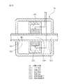
42はマニホールド弁である。マニホールド弁42は本体501、第一弁体510、第二弁体511、駆動部512、513で形成される。   Reference numeral 42 denotes a manifold valve. The manifold valve 42 is formed by a main body 501, a first valve body 510, a second valve body 511, and drive units 512 and 513.

501は本体であり、本体501の上部には連結流路502によって連通されている円筒状の第一弁室503と、第二弁室504が設けられている。第一弁室503の底部中央には第一連通口505が設けられ、第一連通口505には第一供給ライン27bに連通する第一流路507が設けられている。第二弁室504の底部中央には第二連通口506が設けられ、第二連通口506には第二供給ライン28bに連通する第二流路508が設けられている。また第一弁室503にはマニホールド弁内で混合された流体が流出する分岐流路509が連通して設けられている。第一流路507と第二流路508は平行に本体501の同じ側面に設けられ、分岐流路509は該流路507、508に対して直交する方向に設けられている。   Reference numeral 501 denotes a main body, and a cylindrical first valve chamber 503 and a second valve chamber 504 communicated by a connection flow path 502 are provided on the upper portion of the main body 501. A first series opening 505 is provided in the center of the bottom of the first valve chamber 503, and a first flow path 507 communicating with the first supply line 27 b is provided in the first series opening 505. A second communication port 506 is provided at the bottom center of the second valve chamber 504, and a second flow path 508 communicating with the second supply line 28 b is provided at the second communication port 506. The first valve chamber 503 is provided with a branch channel 509 through which fluid mixed in the manifold valve flows out. The first flow path 507 and the second flow path 508 are provided in parallel on the same side surface of the main body 501, and the branch flow path 509 is provided in a direction orthogonal to the flow paths 507 and 508.

510は第一連通口505を開放、遮断を行う第一弁体であり、第一弁室503に収容されている。511は第二連通口506を開放、遮断を行う第二弁体であり、第二弁室504に収容されている。512は第一弁体510の開閉動作を行う駆動部であり、513は第二弁体511の開閉動作を行う駆動部である。駆動部512、513の構成は、図5の開閉弁の駆動部102と同じ構成であるので説明を省略する。各供給ラインの構成は第三の実施例と同様なので説明を省略する。   Reference numeral 510 denotes a first valve body that opens and closes the first series opening 505, and is accommodated in the first valve chamber 503. Reference numeral 511 denotes a second valve body that opens and closes the second communication port 506 and is accommodated in the second valve chamber 504. Reference numeral 512 denotes a drive unit that opens and closes the first valve body 510, and reference numeral 513 denotes a drive unit that opens and closes the second valve body 511. The configuration of the drive units 512 and 513 is the same as that of the drive unit 102 of the on-off valve in FIG. Since the configuration of each supply line is the same as that of the third embodiment, the description thereof is omitted.

次に、本発明の第五の実施例である流体混合装置の作動について説明する。   Next, the operation of the fluid mixing apparatus according to the fifth embodiment of the present invention will be described.

ここでは第一供給ライン27bに純水を流入させ、第二供給ライン28bにフッ化水素酸を流入させ、純水:フッ化水素酸=10:1になるように混合する。マニホールド弁42の駆動部512で第一弁体510を上昇させて第一連通口505を開状態とし、駆動部513で第二弁体511を上昇させて第二連通口506が開状態にした場合(図13の状態)、第一供給ライン27bで制御された純水は第一流路507を通って第一弁室503に流入し、第二供給ライン28bで制御されたフッ化水素酸は第二流路508を通って第二弁室504に流入し、第二弁室504で純水及びフッ化水素酸は合流し、設定された比率(第一供給ライン27bと第二供給ライン28bの流量の比率が10:1)で混合され、設定された流量で分岐流路509から流出される。混合された混合流体は流体混合装置から基板の洗浄装置の洗浄槽内に導入され、基板の酸化膜除去が行なわれる。   Here, pure water is allowed to flow into the first supply line 27b, and hydrofluoric acid is allowed to flow into the second supply line 28b, and mixing is performed so that pure water: hydrofluoric acid = 10: 1. The first valve body 510 is raised by the drive unit 512 of the manifold valve 42 to open the first communication port 505, and the second valve body 511 is raised by the drive unit 513 to open the second communication port 506. In this case (state of FIG. 13), the pure water controlled by the first supply line 27b flows into the first valve chamber 503 through the first flow path 507, and hydrofluoric acid controlled by the second supply line 28b. Flows into the second valve chamber 504 through the second flow path 508, and the pure water and hydrofluoric acid merge in the second valve chamber 504, and set ratio (the first supply line 27b and the second supply line). The ratio of the flow rate of 28b is mixed at 10: 1), and flows out from the branch channel 509 at the set flow rate. The mixed fluid mixed is introduced into the cleaning tank of the substrate cleaning device from the fluid mixing device, and the oxide film on the substrate is removed.

同様に駆動部512、513を駆動させて、第一連通口505を開状態、第二連通口506を閉状態にした場合、第二供給ライン28bは閉止されて流れずに、第一供給ライン27bで制御された純水は第一流路507、第一弁室503、第二弁室504を通って分岐流路509から流出される。   Similarly, when the drive units 512 and 513 are driven to open the first series port 505 and the second communication port 506 to be closed, the second supply line 28b is closed and does not flow, but the first supply The pure water controlled by the line 27 b flows out from the branch flow path 509 through the first flow path 507, the first valve chamber 503, and the second valve chamber 504.

同様に駆動部512、513を駆動させて、第一連通口505を閉状態、第二連通口506を開状態にした場合、第一供給ライン27bは閉止されて流れずに、第二供給ライン28bで制御されたフッ化水素酸は第二流路508、第二弁室504を通って分岐流路509から流出される。各供給ラインの作動は第三の実施例と同様なので説明を省略する。   Similarly, when the drive units 512 and 513 are driven to close the first communication port 505 and the second communication port 506 to the open state, the first supply line 27b is closed and does not flow, and the second supply The hydrofluoric acid controlled by the line 28 b flows out from the branch channel 509 through the second channel 508 and the second valve chamber 504. Since the operation of each supply line is the same as in the third embodiment, the description thereof is omitted.

以上の作動により、マニホールド弁42を設けることにより、第一供給ライン27bの純水、第二供給ライン28bのフッ化水素酸、各流体の混合流体を選んで供給することができ、また各々任意の流量で流出させることができる。また、上記構成により流体混合装置をコンパクトに合流部での流路の切換を行うことができる。   With the above operation, by providing the manifold valve 42, it is possible to selectively supply pure water of the first supply line 27b, hydrofluoric acid of the second supply line 28b, and mixed fluids of the respective fluids. Can be discharged at a flow rate of In addition, with the above configuration, the fluid mixing device can be switched in a compact manner at the junction.

次に、図15乃至図17に基づいて本発明の第六の実施例である流体混合装置について説明する。   Next, a fluid mixing apparatus according to a sixth embodiment of the present invention will be described with reference to FIGS.

本実施例の流体混合装置は、第三の実施例において、第一、第二供給ラインの最上流側にフラッシング装置43が設けられた構成である。フラッシング装置43の構成は以下の通りである。   In the third embodiment, the fluid mixing apparatus of the present embodiment has a configuration in which a flushing device 43 is provided on the most upstream side of the first and second supply lines. The configuration of the flushing device 43 is as follows.

43は二つの供給ラインを有する装置の最上流側に設置されたフラッシング装置である。フラッシング装置43は、流路が形成された本体531と、流路の開閉を行う駆動部A532、駆動部B533、駆動部C534とで形成されている。その各々の構成は以下の通りである。   43 is a flushing device installed on the most upstream side of the device having two supply lines. The flushing device 43 is formed by a main body 531 in which a flow path is formed, and a drive unit A532, a drive unit B533, and a drive unit C534 that open and close the flow path. Each configuration is as follows.

531はPTFE製の本体である。本体531の上部には略すり鉢形状の弁室A535と弁室B536が設けられ、本体531の下部には弁室C537が設けられており、弁室B536と弁室C537は本体531の上部と下部に略同一軸線上に配置されるように設けられている。弁室A535の底面には後記弁体A550の圧接によって流路の全閉シールを行う弁座が形成され、弁座の中心に設けられた連通口に連通する入口流路A538と弁室A535に連通する出口流路A539を有している。弁室B536および弁室C537も、弁室A535と同様に底面に弁座が形成され、弁室B536にそれぞれ連通する入口流路B540と出口流路B541、弁室C537にそれぞれ連通する入口流路C542と出口流路C543が設けられている。   Reference numeral 531 denotes a PTFE main body. A substantially mortar-shaped valve chamber A535 and a valve chamber B536 are provided on the upper portion of the main body 531, and a valve chamber C537 is provided on the lower portion of the main body 531. The valve chamber B536 and the valve chamber C537 are provided on the upper and lower portions of the main body 531. Are arranged on substantially the same axis. A valve seat is formed on the bottom surface of the valve chamber A535 to fully seal the flow path by pressure contact with a valve body A550 described later. The valve passage A538 and the valve chamber A535 communicate with a communication port provided at the center of the valve seat. It has an outlet channel A539 that communicates. Similarly to the valve chamber A535, the valve chamber B536 and the valve chamber C537 are formed with valve seats on the bottom surface, and the inlet channel B540 and the outlet channel B541 that communicate with the valve chamber B536, respectively, and the inlet channel that communicates with the valve chamber C537, respectively. A C542 and an outlet channel C543 are provided.

また、本体531の一方の側の側面には第一流入口544と第二流入口545が設けられ、他方の側の側面には第一流出口546と第二流出口547が設けられている。第一流入口544に連通する流路は、第一分岐部548で二つの流路に分かれ、入口流路A538と入口流路C542とにそれぞれ連通する流路が形成されている。第一流出口546に連通する流路は、出口流路A539に連通している。第二流入口545に連通する流路は、入口流路B540に連通している。第二流出口547に連通する流路は、第二分岐部549で二つの流路に分かれ、出口流路B541と出口流路C543とにそれぞれ連通する流路が形成されている。また、第一流出口546は第一供給ライン27cに連通し、第二流出口547は第二供給ライン28cに連通する。   Further, a first inlet 544 and a second inlet 545 are provided on one side surface of the main body 531, and a first outlet 546 and a second outlet 547 are provided on the other side surface. The flow path communicating with the first inflow port 544 is divided into two flow paths at the first branch portion 548, and the flow paths communicating with the inlet flow path A538 and the inlet flow path C542 are formed. The channel communicating with the first outlet 546 communicates with the outlet channel A539. The channel communicating with the second inlet 545 communicates with the inlet channel B540. The flow path communicating with the second outlet 547 is divided into two flow paths at the second branch portion 549, and the flow paths communicating with the outlet flow path B541 and the outlet flow path C543 are formed. The first outlet 546 communicates with the first supply line 27c, and the second outlet 547 communicates with the second supply line 28c.

このとき、第一流入口544から入口流路A538、弁室A535、出口流路A539を通って第一流出口546に連通して形成される流路を主ラインである第一ラインと称し、第二流入口545から入口流路B540、弁室B536、出口流路B541を通って第二流出口547に連通して形成される流路を第二ラインと称し、第一分岐部548から入口流路C542、弁室C537、出口流路C543を通って第二分岐部549に連通して形成される流路を連結ラインと称する。   At this time, the flow path formed in communication from the first inlet 544 to the first outlet 546 through the inlet flow path A538, the valve chamber A535, and the outlet flow path A539 is referred to as a first line that is a main line. The flow path formed from the inlet 545 to the second outlet 547 through the inlet channel B540, the valve chamber B536, the outlet channel B541, and the second outlet 547 is referred to as a second line. A flow path formed in communication with the second branch portion 549 through C542, the valve chamber C537, and the outlet flow path C543 is referred to as a connection line.

532、533、534はPVDF製の駆動部A、B、Cである。駆動部A532、駆動部B533、駆動部C534には弁室A535、弁室B536、弁室C537の弁座に圧接離間することで弁の開閉を行う弁体A550、弁体B551、弁体C552が設けられている。該駆動部532、533、534の構成は、図5の開閉弁の駆動部102と同じ構成であるので説明を省略する。   Reference numerals 532, 533, and 534 denote PVDF driving units A, B, and C. The drive unit A532, the drive unit B533, and the drive unit C534 include a valve body A550, a valve body B551, and a valve body C552 that open and close the valve by pressing and separating from the valve seats of the valve chamber A535, the valve chamber B536, and the valve chamber C537. Is provided. The configuration of the drive units 532, 533, and 534 is the same as that of the drive unit 102 of the on-off valve in FIG.

ここで、図14における開閉弁535aは図15、図16における弁室A535と駆動部A532の弁体A550によって形成される部分にあたり、開閉弁536aは弁室B536と駆動部B533の弁体B551によって形成される部分にあたり、開閉弁537aは弁室C537と駆動部C534の弁体C552によって形成される部分にあたる。各供給ラインの構成は第三の実施例と同様なので説明を省略する。   Here, the on-off valve 535a in FIG. 14 corresponds to a portion formed by the valve chamber A535 in FIG. 15 and FIG. 16 and the valve body A550 of the drive unit A532, and the on-off valve 536a is formed by the valve body B536 and the valve body B551 of the drive unit B533. In the formed portion, the on-off valve 537a corresponds to a portion formed by the valve chamber C537 and the valve body C552 of the drive unit C534. Since the configuration of each supply line is the same as that of the third embodiment, the description thereof is omitted.

次に、本発明の第六の実施例である流体混合装置の作動について説明する。   Next, the operation of the fluid mixing apparatus according to the sixth embodiment of the present invention will be described.

ここでは第一供給ライン27cに純水を流入させ、第二供給ライン28cに塩酸を流入させ、純水:塩酸=20:1になるように混合する。通常モードにおいては、弁体A550と弁体B551を上方へ引き上げて弁室A535と弁室B536を開状態とし、弁体C552を下方へ押し下げて弁室C537を閉状態とする(図5の状態)。このとき第一ラインと第二ラインに各々独立して純水および塩酸が流れるようになる。ここで第一流入口544に純水を流入させ、第二流入口545に塩酸を流入させると、第一流入口544に流入した純水は入口流路A538、弁室A535、出口流路A539を通過して第一流出口546から第一供給ライン27cに流入し、第二流入口545に流入した塩酸は入口流路B540、弁室B536、出口流路B541を通過して第二流出口547から第二供給ライン28cに流入することになる。各供給ラインの作用は第三の実施例と同様であるので説明を省略する。このとき、第一供給ライン27cと第二供給ライン28cは20:1の流量比率で混合され、設定された流量で流出される。流出された混合流体は流体混合装置から基板の洗浄装置の洗浄槽内に導入され、基板の酸化膜除去が行なわれる。   Here, pure water is introduced into the first supply line 27c, hydrochloric acid is introduced into the second supply line 28c, and mixing is performed so that pure water: hydrochloric acid = 20: 1. In the normal mode, the valve body A550 and the valve body B551 are pulled upward to open the valve chamber A535 and the valve chamber B536, and the valve body C552 is pushed downward to close the valve chamber C537 (the state shown in FIG. 5). ). At this time, pure water and hydrochloric acid flow independently through the first line and the second line. When pure water is introduced into the first inlet 544 and hydrochloric acid is introduced into the second inlet 545, the pure water that has entered the first inlet 544 passes through the inlet channel A538, the valve chamber A535, and the outlet channel A539. Then, the hydrochloric acid flowing into the first supply line 27c from the first outlet 546 and flowing into the second inlet 545 passes through the inlet channel B540, the valve chamber B536, and the outlet channel B541 and passes through the second outlet 547. It will flow into the two supply lines 28c. Since the operation of each supply line is the same as that of the third embodiment, description thereof is omitted. At this time, the first supply line 27c and the second supply line 28c are mixed at a flow rate ratio of 20: 1 and flow out at a set flow rate. The mixed fluid that has flowed out is introduced into the cleaning tank of the substrate cleaning apparatus from the fluid mixing apparatus, and the oxide film on the substrate is removed.

フラッシングモードにおいては、弁体A550と弁体B551を下方へ押し下げて弁室A535と弁室B536を閉状態とし、弁体C552を上方へ引き上げて弁室C537を開状態とする。このとき第一ラインと第二ラインが連結ラインによって繋がり、第一流入口544から第二流出口547に流れる流路が形成される。ここで第一供給ライン27cに流れる純水が、第一流入口544から第一分岐部548、入口流路C542、弁室C537、出口流路C543、第二分岐部549を通過して、第二流出口547から第二供給ライン28cに流れることができ、純水が流し続けられることにより第二供給ライン28cを純水でフラッシングして第二供給ライン28c内の洗浄を行うことができる。   In the flushing mode, the valve body A550 and the valve body B551 are pushed downward to close the valve chamber A535 and the valve chamber B536, and the valve body C552 is lifted upward to open the valve chamber C537. At this time, the first line and the second line are connected by the connecting line, and a flow path that flows from the first inlet 544 to the second outlet 547 is formed. Here, the pure water flowing through the first supply line 27c passes through the first inlet 544 through the first branch 548, the inlet channel C542, the valve chamber C537, the outlet channel C543, and the second branch 549, and then passes through the second branch 549. The pure water can flow from the outlet 547 to the second supply line 28c, whereby the second supply line 28c can be flushed with pure water to clean the second supply line 28c.

以上の作動により、本実施例のフラッシング装置43を設けることにより、通常モードとフラッシングモードを容易に選択でき、フラッシングモードにより各供給ラインをフラッシングすることで洗浄を行うことができる。また、本実施例のフラッシング装置43は本体531である一つのベースブロックに流路が形成されることにより、フラッシング装置43を一つの部材として設けることができ、フラッシング装置43の流路を配管などで設ける必要がないので部品点数が少なくて済み、フラッシング装置43をよりコンパクトに形成でき、流路が短くできるので流体抵抗を抑えることができる。   By providing the flushing device 43 of the present embodiment by the above operation, the normal mode and the flushing mode can be easily selected, and cleaning can be performed by flushing each supply line in the flushing mode. Further, the flushing device 43 of the present embodiment can be provided as a single member by forming a flow path in one base block which is the main body 531, and the flow path of the flushing apparatus 43 is connected to a pipe or the like. Therefore, the number of parts can be reduced, the flushing device 43 can be formed more compactly, and the flow path can be shortened, so that the fluid resistance can be suppressed.

次に、図18、図19に基づいて本発明の第七の実施例の流体混合装置について説明する。   Next, a fluid mixing apparatus according to a seventh embodiment of the present invention will be described with reference to FIGS.

本実施例の流体混合装置は、第三の実施例において(図7参照)、第一供給ライン27の流量計測器30と第一流体制御弁31の位置を逆にして、開閉弁29、第一流体制御弁31、流量計測器30、絞り弁32の順にして形成した装置である。流量計測器30と第一流体制御弁31の位置を逆にしたのは、隣り合う弁同士を一つのベースブロックに配設し易くするためであり、位置を逆にしてもフィードバック制御を問題なく行うことができる。各構成は以下の通りである。これにより、第一、第二供給ライン27d、28dの開閉弁29d、34d、第一流体制御弁31dおよび圧力調整弁35dが一つのベースブロック44に配設され、絞り弁32dと流体制御弁37dが一つのベースブロック45に配設され、流量計測器30d、36dが各ベースブロック44、45にそれぞれ接続部材46、47、48、49を介在させて接続されている。これは別体のチューブや管を用いない場合の直接接続する方法である。各構成は以下の通りである。   In the third embodiment (see FIG. 7), the fluid mixing device of the present embodiment is configured such that the position of the flow rate measuring device 30 and the first fluid control valve 31 in the first supply line 27 are reversed, and the on-off valve 29, It is a device formed by sequentially arranging a single fluid control valve 31, a flow rate measuring device 30, and a throttle valve 32. The reason why the positions of the flow rate measuring device 30 and the first fluid control valve 31 are reversed is to make it easier to arrange adjacent valves in one base block. It can be carried out. Each configuration is as follows. As a result, the on-off valves 29d and 34d of the first and second supply lines 27d and 28d, the first fluid control valve 31d, and the pressure regulating valve 35d are arranged in one base block 44, and the throttle valve 32d and the fluid control valve 37d. Are disposed in one base block 45, and flow rate measuring devices 30d and 36d are connected to the base blocks 44 and 45 with connection members 46, 47, 48 and 49 interposed therebetween, respectively. This is a direct connection method when a separate tube or tube is not used. Each configuration is as follows.

44は第一、第二供給ライン27d、28dの開閉弁29d、34d、第一流体制御弁31dおよび圧力調整弁35dが配設されたベースブロックである。ベースブロック45には、第一供給ライン27dの開閉弁29d、第一流体制御弁31dの流路と、第二供給ライン28dの開閉弁34d、圧力調整弁35dの流路が、この順でそれぞれ連通して形成されている。   44 is a base block in which the on-off valves 29d and 34d, the first fluid control valve 31d and the pressure regulating valve 35d of the first and second supply lines 27d and 28d are arranged. In the base block 45, the on-off valve 29d of the first supply line 27d and the flow path of the first fluid control valve 31d, the on-off valve 34d of the second supply line 28d, and the flow path of the pressure adjustment valve 35d are respectively in this order. It is formed in communication.

45は第一、第二供給ライン27d、28dの絞り弁32dおよび第二流体制御弁37dが配設されたベースブロックである。ベースブロック45には第一供給ライン27dの絞り弁32dの流路と、第二供給ライン28dの第二流体制御弁37dの流路がそれぞれ形成されている。また、第一供給ライン27dの絞り弁32dの出口流路は、第二供給ライン28dの第二流体制御弁37dの出口流路と連通して合流部39dを形成し、合流部39dから流出口50に連通している。なお、合流部39dはベースブロック45内に設けずに、ベースブロック45の各供給ラインから流出した流路を合流するようにしても良い。   Reference numeral 45 denotes a base block in which throttle valves 32d and second fluid control valves 37d of the first and second supply lines 27d and 28d are disposed. In the base block 45, a flow path of the throttle valve 32d of the first supply line 27d and a flow path of the second fluid control valve 37d of the second supply line 28d are formed. Further, the outlet flow path of the throttle valve 32d of the first supply line 27d communicates with the outlet flow path of the second fluid control valve 37d of the second supply line 28d to form a joining portion 39d, and the outlet from the joining portion 39d. 50. Note that the merging portion 39d may not be provided in the base block 45 but may merge the flow paths that have flowed out from the supply lines of the base block 45.

46、47、48、49は流路の方向転換を行う接続部材である。第一流体制御弁31dおよび圧力調整弁35dの出口流路から接続部材46、48を介して流路の方向転換が行なわれて流量計測器30d、36dの入口流路に各々直接接続され、流量計測器30d、36dの出口流路から接続部材47、49を介して流路の方向転換が行なわれて絞り弁32dおよび第二流体制御弁37dの入口流路に各々直接接続されて連通している。各供給ラインの弁および流量計測器の構成と作動は第三の実施例と同様なので説明を省略する。   46, 47, 48, and 49 are connecting members that change the direction of the flow path. The direction of the flow path is changed from the outlet flow path of the first fluid control valve 31d and the pressure regulating valve 35d via the connection members 46 and 48, and the flow paths are directly connected to the inlet flow paths of the flow rate measuring devices 30d and 36d, respectively. The direction of the flow path is changed from the outlet flow paths of the measuring instruments 30d and 36d through the connecting members 47 and 49, and the direct connection is made to the inlet flow paths of the throttle valve 32d and the second fluid control valve 37d. Yes. The configuration and operation of the valves and flow rate measuring instruments of each supply line are the same as those in the third embodiment, and the description thereof is omitted.

これにより、隣り合う弁および流量計測器が独立した接続手段であるチューブや管を用いずに直接接続されているため、流体混合装置をコンパクトにして設置場所のスペースを少なくすることができる。また、設置作業が容易になり作業時間が短縮することができ、流体混合装置内の流路を短くさせることで流体抵抗を抑えることができる。   Thereby, since the adjacent valve and the flow rate measuring device are directly connected without using a tube or pipe which is an independent connecting means, the fluid mixing device can be made compact and the space of the installation place can be reduced. Moreover, installation work becomes easy and working time can be shortened, and fluid resistance can be suppressed by shortening the flow path in the fluid mixing apparatus.

次に、図20、図21に基づいて本発明の第八の実施例の流体混合装置について説明する。   Next, based on FIG. 20, FIG. 21, the fluid mixing apparatus of the 8th Example of this invention is demonstrated.

本実施例の流体混合装置は、第三の実施例において(図7参照)、第一供給ライン27の流量計測器30と第一流体制御弁31の位置を逆にして、開閉弁29、第一流体制御弁31、流量計測器30、絞り弁32の順にして形成した装置である。各構成は以下の通りである。   In the third embodiment (see FIG. 7), the fluid mixing device of the present embodiment is configured such that the position of the flow rate measuring device 30 and the first fluid control valve 31 in the first supply line 27 are reversed, and the on-off valve 29, It is a device formed by sequentially arranging a single fluid control valve 31, a flow rate measuring device 30, and a throttle valve 32. Each configuration is as follows.

51は第一、第二供給ライン27e、28eの開閉弁29e、34e、流量計測器30e、36e、絞り弁32e、圧力調整弁35e、第一流体制御弁31e、第二流体制御弁37eが配設されたベースブロックである。ベースブロック51には第一供給ライン27eの開閉弁29e、第一流体制御弁31e、流量計測器30eおよび絞り弁32eの流路と、第二供給ラインの開閉弁34e、圧力調整弁35e、流量計測器36eおよび第二流体制御弁37eの流路が、この順でそれぞれ連通して形成されている。また、第一供給ライン27eの絞り弁32eの出口流路は、第二供給ライン28eの第二流体制御弁37eの出口流路と連通して合流部39eを形成し、合流部39eから流出口52に連通する。なお、合流部39eはベースブロック51内に設けずに、ベースブロック51の各供給ラインから流出した流路を合流するようにしても良い。各供給ラインの弁および流量計測器の構成と作動は第三の実施例と同様なので説明を省略する。   51 includes on-off valves 29e and 34e of the first and second supply lines 27e and 28e, flow rate measuring devices 30e and 36e, a throttle valve 32e, a pressure adjusting valve 35e, a first fluid control valve 31e, and a second fluid control valve 37e. This is a base block. The base block 51 includes an on-off valve 29e of the first supply line 27e, a first fluid control valve 31e, a flow path of a flow rate measuring device 30e and a throttle valve 32e, an on-off valve 34e of the second supply line, a pressure adjusting valve 35e, a flow rate. The flow paths of the measuring instrument 36e and the second fluid control valve 37e are formed in communication in this order. In addition, the outlet flow path of the throttle valve 32e of the first supply line 27e communicates with the outlet flow path of the second fluid control valve 37e of the second supply line 28e to form a merging portion 39e, and the outlet from the merging portion 39e. 52 communicates. In addition, you may make it join the flow path which flowed out from each supply line of the base block 51, without providing the junction part 39e in the base block 51. FIG. The configuration and operation of the valves and flow rate measuring instruments of each supply line are the same as those in the third embodiment, and the description thereof is omitted.

これにより、流体混合装置が流路の形成された一つのベースブロック51に配設されているため、流体混合装置をコンパクトにして設置場所のスペースを少なくすることができる。また、設置作業が容易になり作業時間が短縮でき、流体混合装置内の流路を短くさせることで流体抵抗を抑えることができ、さらに部品点数を少なくすることができるので流体混合装置の組み立てを容易にすることができる。   Thereby, since the fluid mixing apparatus is disposed in one base block 51 in which the flow path is formed, it is possible to make the fluid mixing apparatus compact and to reduce the installation space. In addition, the installation work becomes easy, the work time can be shortened, the fluid resistance can be suppressed by shortening the flow path in the fluid mixing device, and the number of parts can be reduced, so that the fluid mixing device can be assembled. Can be easily.

次に、図22に基づいて本発明の第九の実施例の流体混合装置について説明する。なお、本実施例では図22で示した第二供給ライン側の縦断面図のみで説明する。   Next, a fluid mixing apparatus according to a ninth embodiment of the present invention will be described with reference to FIG. In the present embodiment, only the longitudinal sectional view on the second supply line side shown in FIG. 22 will be described.

本実施例の流体混合装置は、第三の実施例において、第一、第二供給ライン28fの開閉弁34f、流量計測器36f、第二流体制御弁37f、圧力調整弁35fが一つのケーシング53内に収納配設されている。各構成は以下の通りである。   In the third embodiment, the fluid mixing apparatus of the present embodiment is a casing 53 in which the on-off valve 34f, the flow rate measuring device 36f, the second fluid control valve 37f, and the pressure adjusting valve 35f of the first and second supply lines 28f are one. It is stored and arranged inside. Each configuration is as follows.

53はPVDF製のケーシングである。ケーシング53内には、ケーシング53の底面に開閉弁34f、圧力調整弁35f、流量計測器36f、第二流体制御弁37fがこの順でボルト、ナット(図示せず)にて固定されている。また、制御部は流量計測器36fの上方にケーシング53の上部に固定設置されている。本実施例の弁および流量計測器の接続構造は実施例7と同様であり、各供給ラインの弁および流量計測器の構成と作動は第三の実施例と同様なので説明を省略する。   53 is a PVDF casing. In the casing 53, an opening / closing valve 34f, a pressure adjusting valve 35f, a flow rate measuring device 36f, and a second fluid control valve 37f are fixed to the bottom surface of the casing 53 in this order by bolts and nuts (not shown). The control unit is fixedly installed above the casing 53 above the flow rate measuring device 36f. The connection structure of the valve and the flow rate measuring instrument of the present embodiment is the same as that of the seventh embodiment, and the configuration and operation of the valve and the flow rate measuring instrument of each supply line are the same as those of the third embodiment, so that the description thereof is omitted.

これにより、流体混合装置が一つのケーシング53内に設置されて流体混合装置が一つのモジュールとなるため、設置が容易になり、設置作業の作業時間が短縮でき、各部品がケーシングによって保護されると共に、流体混合装置をブラックボックス化することで安易に流体混合装置を分解させることを防ぎ、不慣れな利用者が流体混合装置を分解することにより不具合が生じることを防止することができる。   Thereby, since the fluid mixing apparatus is installed in one casing 53 and the fluid mixing apparatus becomes one module, the installation becomes easy, the work time of the installation work can be shortened, and each component is protected by the casing. In addition, it is possible to prevent the fluid mixing device from being easily disassembled by making the fluid mixing device into a black box, and it is possible to prevent troubles caused by disassembling the fluid mixing device by an unfamiliar user.

次に、図23、図24に基づいて本発明の第十の実施例について説明する。ここでは第一の実施例の第一流体制御弁4が、他の流体制御弁である本実施例の第一流体制御弁4aである場合で説明する。   Next, a tenth embodiment of the present invention will be described with reference to FIGS. Here, the case where the first fluid control valve 4 of the first embodiment is the first fluid control valve 4a of this embodiment which is another fluid control valve will be described.

4aは第一流体制御弁である。第一流体制御弁4aは本体部121、弁部材136、第一ダイヤフラム部137、第二ダイヤフラム部138、第三ダイヤフラム部139、第四ダイヤフラム部140で形成される。   4a is a first fluid control valve. The first fluid control valve 4 a is formed by a main body 121, a valve member 136, a first diaphragm portion 137, a second diaphragm portion 138, a third diaphragm portion 139, and a fourth diaphragm portion 140.

本体部121は、内部に後記第一加圧室128、第二弁室129、第一弁室130及び第二加圧室131に区切られるチャンバ127と、流体が外部からチャンバ127へ流入するための入口流路145及びチャンバ127から流出するための出口流路152とを有し、上から本体D125、本体C124、本体B123、本体A122、本体E126に分かれており、これらを一体に組みつけて構成されている。   The main body 121 has a chamber 127 that is divided into a first pressurizing chamber 128, a second valve chamber 129, a first valve chamber 130, and a second pressurizing chamber 131, and fluid flows into the chamber 127 from the outside. The inlet channel 145 and the outlet channel 152 for flowing out from the chamber 127 are divided into a main body D125, a main body C124, a main body B123, a main body A122, and a main body E126 from above, and these are assembled together. It is configured.

122は本体部121の内側に位置するPTFE製の本体Aであり、上部に平面円形状の段差部141が設けられ、段差部141の中央には段差部141より小径で、下部第一弁室134となる開孔部142が、また、開孔部142の下には開孔部142の径より大径の平面円形状の下部段差部143が連続して設けられている。本体A122の上面部、すなわち段差部141の周縁部には環状凹溝144が設けられ、また、側面から本体A122の開孔部142に連通する入口流路145が設けられている。   Reference numeral 122 denotes a PTFE main body A located inside the main body 121, and a flat circular stepped portion 141 is provided in the upper portion, and the lower first valve chamber has a smaller diameter than the stepped portion 141 at the center of the stepped portion 141. An opening 142 serving as a hole 134 is provided, and a lower planar step 143 having a planar circular shape having a diameter larger than the diameter of the opening 142 is continuously provided below the opening 142. An annular groove 144 is provided on the upper surface of the main body A122, that is, the peripheral edge of the stepped portion 141, and an inlet channel 145 that communicates with the opening 142 of the main body A122 from the side surface.

123は本体A122の上面に係合固定されているPTFE製の本体Bであり、上部に平面円形状の段差部146が設けられ、段差部146の中央には段差部146より小径の上部第二弁室133となる開孔部147が設けられている。また、開孔部147の下には開孔部147の径より小径の開口部148と、本体A122の段差部141と同じ径の平面円形状の下部段差部149が連続して設けられている。開口部148の下端周囲は弁座150となっている。本体B123の下面部すなわち下部段差部149の周縁部には本体A122の環状凹溝144と相対する位置に環状凹溝151が設けられ、また、本体A122の入口流路145と反対側に位置する本体B123の側面から開孔部147に連通する出口流路152が設けられている。   123 is a PTFE main body B which is engaged and fixed to the upper surface of the main body A122. A flat circular stepped portion 146 is provided on the upper portion, and an upper second portion having a smaller diameter than the stepped portion 146 is provided at the center of the stepped portion 146. An opening 147 serving as the valve chamber 133 is provided. Further, an opening 148 having a diameter smaller than the diameter of the opening 147 and a planar circular lower step 149 having the same diameter as the step 141 of the main body A 122 are provided continuously below the opening 147. . A valve seat 150 is provided around the lower end of the opening 148. An annular groove 151 is provided at a position opposite to the annular groove 144 of the main body A122 on the lower surface of the main body B123, that is, the peripheral edge of the lower step 149, and is located on the opposite side of the main body A122 from the inlet channel 145. An outlet channel 152 communicating with the opening 147 from the side surface of the main body B123 is provided.

124は本体B123の上部に嵌合固定されているPTFE製の本体Cであり、中央に本体C124の上下端面を貫通し上部で拡径した平面円形状のダイヤフラム室153と、ダイヤフラム室153と外部とを連通する呼吸孔154、及び下端面に本体B123の段差部146に嵌合される環状突部155がダイヤフラム室153を中心として設けられている。   A PTFE main body C is fitted and fixed to the upper portion of the main body B123. A flat circular diaphragm chamber 153 that penetrates the upper and lower end surfaces of the main body C124 in the center and expands in diameter at the upper portion, and the diaphragm chamber 153 and the outside And an annular protrusion 155 fitted to the stepped portion 146 of the main body B123 at the lower end surface thereof is provided around the diaphragm chamber 153.

125は本体C124の上部に位置するPTFE製の本体Dであり、下部に気室156と、中央に上面を貫通して設けられ、外部から気室156へと圧縮空気を導入するための給気孔157が設けられている。また、側面を貫通して設けられる微孔の排出孔180が設けられている。なお、排出孔180は圧縮空気の供給において必要ない場合は設けなくてもかまわない。   Reference numeral 125 denotes a PTFE main body D located at the upper part of the main body C124. The lower part is an air chamber 156 provided in the lower part and the upper surface is penetrated through the upper surface, and an air supply hole for introducing compressed air into the air chamber 156 from the outside. 157 is provided. In addition, a minute discharge hole 180 provided through the side surface is provided. The discharge hole 180 may not be provided if it is not necessary for supplying compressed air.

126は本体A122の底部に嵌合固定されるPVDF製の本体Eであり、中央部には上面に開口した、第二加圧室131となる開孔部158が設けられ、開孔部158上面の周囲には、本体A122の下部段差部143に嵌合固定される環状突部159が設けられている。また、本体E126の側面には、そこから開孔部158に連通する小径の呼吸孔160が設けられている。   126 is a PVDF main body E that is fitted and fixed to the bottom of the main body A122. The central portion is provided with an opening portion 158 that opens to the upper surface and serves as the second pressurizing chamber 131, and the upper surface of the opening portion 158. Is provided with an annular protrusion 159 fitted and fixed to the lower step 143 of the main body A122. Further, a small-diameter breathing hole 160 that communicates with the opening 158 from the side surface of the main body E126 is provided.

以上説明した本体部121を構成する5つの本体A122、本体B123、本体C124、本体D125、本体E126はボルト・ナット(図示せず)で挟持固定されている。   The five main bodies A122, main body B123, main body C124, main body D125, and main body E126 constituting the main body 121 described above are clamped and fixed by bolts and nuts (not shown).

136はPTFE製の弁部材であり、中央に鍔状に設けられた肉厚部161と肉厚部161を貫通して設けられた連通孔162、肉厚部161の外周面から径方向に延出して設けられた円形状の薄膜部163及び薄膜部163の外周縁部に上下に突出して設けられた環状リブ部164を有する第一ダイヤフラム部137と、第一ダイヤフラム部137の上部中央に設けられ逆すり鉢状の弁体165と、弁体165の上部より上方に突出して設けられ、上端部が略半球状に形成された上部ロッド166び肉厚部161下端面中央部より下方に突出して設けられ、下端部が略半球状に形成された下部ロッド167有し、かつ、一体的に形成されている。第一ダイヤフラム部137の外周縁部に設けられた環状リブ部164は本体A122と本体B123に設けられた両環状凹溝144、151に嵌合され、本体A122と本体B123に挟持固定されている。また、弁体165の傾斜面と本体B123の開口部148の下端面周縁部との間に形成される空間は流体制御部168になっている。   Reference numeral 136 denotes a PTFE valve member, which extends in the radial direction from the thick part 161 provided in the shape of a bowl at the center, the communication hole 162 provided through the thick part 161, and the outer peripheral surface of the thick part 161. A first thin film portion 137 having a circular thin film portion 163 that is provided and an annular rib portion 164 that protrudes vertically from the outer peripheral edge of the thin film portion 163, and an upper central portion of the first diaphragm portion 137. An inverted mortar-shaped valve body 165 and an upper rod 166 provided to protrude upward from the upper portion of the valve body 165 and having an upper end formed substantially hemispherical and protruded downward from the central portion of the lower end surface of the thick portion 161. The lower rod 167 is provided and the lower end portion is formed in a substantially hemispherical shape, and is integrally formed. An annular rib portion 164 provided at the outer peripheral edge of the first diaphragm portion 137 is fitted into both annular concave grooves 144 and 151 provided in the main body A 122 and the main body B 123, and is sandwiched and fixed between the main body A 122 and the main body B 123. . A space formed between the inclined surface of the valve body 165 and the peripheral edge of the lower end surface of the opening 148 of the main body B123 is a fluid control unit 168.

138はPTFE製の第二ダイヤフラム部であり、中央に円柱状の肉厚部169と肉厚部169の下端面から径方向に延出して設けられた円形状の薄膜部170、及び薄膜部170の外周縁部に設けられた環状シール部171を有し、かつ一体的に形成されている。また、薄膜部170の周縁部の環状シール部171は本体B123の上部の段差部146と、本体C124の環状突部155とに挟持固定されている。なお、第二ダイヤフラム部138の受圧面積は、第一ダイヤフラム部137のそれよりも小さく設ける必要がある。   Reference numeral 138 denotes a PTFE second diaphragm portion, which is a cylindrical thick portion 169 at the center, a circular thin film portion 170 provided in a radial direction from the lower end surface of the thick portion 169, and the thin film portion 170. It has the annular seal part 171 provided in the outer peripheral edge part, and is formed integrally. Further, the annular seal portion 171 at the peripheral edge of the thin film portion 170 is sandwiched and fixed between the stepped portion 146 at the upper portion of the main body B123 and the annular protrusion 155 of the main body C124. The pressure receiving area of the second diaphragm portion 138 needs to be provided smaller than that of the first diaphragm portion 137.

139はPTFE製の第三ダイヤフラム部で、形状は第二ダイヤフラム部138と同一になっており、上下逆にして配置されている。肉厚部172の上端面は弁部材136の下部ロッド167と接触しており、また、薄膜部173の周縁部の環状シール部174は本体A122の下部段差部143と本体E126の環状突部159とに挟持固定されている。なお、第三ダイヤフラム部139の受圧面積も上記と同様に第一ダイヤフラム部137のそれよりも小さく設ける必要がある。   Reference numeral 139 denotes a third diaphragm portion made of PTFE, which has the same shape as the second diaphragm portion 138, and is arranged upside down. The upper end surface of the thick part 172 is in contact with the lower rod 167 of the valve member 136, and the annular seal part 174 at the peripheral part of the thin film part 173 is the lower step part 143 of the main body A122 and the annular protrusion 159 of the main body E126. It is clamped and fixed. In addition, it is necessary to provide the pressure receiving area of the third diaphragm part 139 smaller than that of the first diaphragm part 137 as described above.

140は第四ダイヤフラム部であり、周縁部に外径が本体C124のダイヤフラム室153と略同径の円筒形リブ175と、中央に円柱部176、及び円筒形リブ175の下端面内周と円柱部176の上端面外周とをつないで設けられた膜部177を有する。円筒形リブ175は本体C124のダイヤフラム室153に嵌合固定されるとともに、本体B123と本体C124の間で挟持固定され、円柱部176はダイヤフラム室153の中で上下動自在となっている。また、円柱部176の下部は、第二ダイヤフラム部138の肉厚部169が嵌合されている。   Reference numeral 140 denotes a fourth diaphragm portion, which has a cylindrical rib 175 having an outer diameter substantially the same as that of the diaphragm chamber 153 of the main body C124 at the peripheral portion, a column portion 176 at the center, and an inner periphery of the lower end surface of the cylindrical rib 175 and a column. The film portion 177 is provided so as to be connected to the outer periphery of the upper end surface of the portion 176. The cylindrical rib 175 is fitted and fixed to the diaphragm chamber 153 of the main body C124, and is clamped and fixed between the main body B123 and the main body C124, and the columnar portion 176 is movable up and down in the diaphragm chamber 153. Further, the thick part 169 of the second diaphragm part 138 is fitted to the lower part of the cylindrical part 176.

178および179は本体E126の開孔部158に配置されたPVDF製のバネ受けとSUS製のバネである。両者は第三ダイヤフラム部139を内向き(図では上向き)に加圧している。   Reference numerals 178 and 179 denote a PVDF spring receiver and a SUS spring disposed in the opening 158 of the main body E126. Both pressurize the third diaphragm part 139 inward (in the figure, upward).

以上説明した各構成により本体部121の内部に形成されたチャンバ127は上から、第四ダイヤフラム部140及び本体D125気室156から形成された第一加圧室128、第一ダイヤフラム部137と本体B123の下部段差部149との間に形成された下部第二弁室132と第二ダイヤフラム部138と本体B123の開孔部147とから形成された上部第二弁室133の両者からなる第二弁室129、第三ダイヤフラム部139と本体A122の開孔部142とで形成された下部第一弁室134と第一ダイヤフラム部137と本体A122の段差部141とで形成された上部第一弁室135からなる第一弁室130、及び第三ダイヤフラム部139と本体E126の開孔部158とで形成された第二加圧室131に区分されていることがわかる。   From the top, the chamber 127 formed in the main body 121 by the above-described configuration is arranged from the top to the first pressurizing chamber 128, the first diaphragm portion 137 and the main body formed from the fourth diaphragm portion 140 and the main body D125 air chamber 156. A second second valve chamber 132 formed between the lower second valve chamber 132 formed between the lower step portion 149 of B123, the second diaphragm portion 138, and the opening portion 147 of the main body B123. Upper first valve formed by the lower first valve chamber 134 formed by the valve chamber 129, the third diaphragm portion 139, and the opening 142 of the main body A122, the first diaphragm portion 137, and the step portion 141 of the main body A122. A first valve chamber 130 including a chamber 135, and a second pressurizing chamber 131 formed by a third diaphragm portion 139 and an opening portion 158 of the main body E126. Togawakaru.

次に、本発明の第十の実施例の作動について説明する。   Next, the operation of the tenth embodiment of the present invention will be described.

電空変換器(図示せず)から供給される操作圧に対する第一流体制御弁4aの作動は以下の通りである。第一流体制御弁4aの本体A122の入口流路145より第一弁室130に流入した流体は、弁部材136の連通孔162を通ることで減圧され下部第二弁室132に流入する。さらに、流体は、下部第二弁室132から流体制御部168を通り上部第二弁室133に流入する際に流体制御部168での圧力損失により再度減圧され出口流路152から流出する。ここで、連通孔162の直径は充分小さく設けてあるため、弁を流れる流量は連通孔162前後の圧力差によって決まっている。   The operation of the first fluid control valve 4a with respect to the operating pressure supplied from the electropneumatic converter (not shown) is as follows. The fluid that has flowed into the first valve chamber 130 from the inlet channel 145 of the main body A 122 of the first fluid control valve 4 a is decompressed by passing through the communication hole 162 of the valve member 136 and flows into the lower second valve chamber 132. Furthermore, when the fluid flows from the lower second valve chamber 132 through the fluid control unit 168 and into the upper second valve chamber 133, the fluid is decompressed again by the pressure loss in the fluid control unit 168 and flows out from the outlet channel 152. Here, since the diameter of the communication hole 162 is sufficiently small, the flow rate flowing through the valve is determined by the pressure difference before and after the communication hole 162.

このとき、各ダイヤフラム部137、138、139が流体から受ける力を見ると、第一ダイヤフラム部137は第一弁室130と下部第二弁室132内の流体圧力差により上方向の、第二ダイヤフラム部138は上部第二弁室133の流体圧力により上方向の、第三ダイヤフラム部139は第一弁室130内の流体圧力により下方向の力を受けている。ここで、第一ダイヤフラム部137の受圧面積は、第二ダイヤフラム部138及び第三ダイヤフラム部139の受圧面積よりも充分大きく設けてあるため、第二、第三ダイヤフラム部138、139に働く力は、第一ダイヤフラム部137に働く力に比べてほとんど無視することができる。したがって、弁部材136が、流体から受ける力は、第一弁室130と下部第二弁室132内の流体圧力差による上方向の力となる。   At this time, when the force that each diaphragm portion 137, 138, 139 receives from the fluid is observed, the first diaphragm portion 137 is moved upwardly by the fluid pressure difference between the first valve chamber 130 and the lower second valve chamber 132. Diaphragm portion 138 receives an upward force due to fluid pressure in upper second valve chamber 133, and third diaphragm portion 139 receives a downward force due to fluid pressure in first valve chamber 130. Here, since the pressure receiving area of the first diaphragm portion 137 is sufficiently larger than the pressure receiving areas of the second diaphragm portion 138 and the third diaphragm portion 139, the force acting on the second and third diaphragm portions 138, 139 is The force acting on the first diaphragm portion 137 can be almost ignored. Therefore, the force that the valve member 136 receives from the fluid is an upward force due to a fluid pressure difference in the first valve chamber 130 and the lower second valve chamber 132.

また、弁部材136は、第一加圧室128の加圧手段により下方へ付勢されており、同時に第二加圧室131の加圧手段により上方へ付勢されている。第一加圧室128の加圧手段の力を第二加圧室131の加圧手段の力より大きく調整しておけば、弁部材136が各加圧手段から受ける合力は下方向の力となる。ここで第一加圧室128の加圧手段とは、電空変換器から供給される操作圧によるものであり、第二加圧室131の加圧手段とは、バネ179の反発力によるものである。   Further, the valve member 136 is biased downward by the pressurizing means of the first pressurizing chamber 128 and simultaneously biased upward by the pressurizing means of the second pressurizing chamber 131. If the force of the pressurizing means in the first pressurizing chamber 128 is adjusted to be larger than the force of the pressurizing means in the second pressurizing chamber 131, the resultant force that the valve member 136 receives from each pressurizing means is a downward force. Become. Here, the pressurizing means of the first pressurizing chamber 128 is based on the operating pressure supplied from the electropneumatic converter, and the pressurizing means of the second pressurizing chamber 131 is based on the repulsive force of the spring 179. It is.

したがって、弁部材136は、各加圧手段による下方向の合力と、第一弁室130と下部第二弁室132内の流体圧力差による上方向の力とが釣り合う位置に安定する。つまり、各加圧手段による合力と流体圧力差による力が釣り合うように、下部第二弁室132の圧力が流体制御部168の開口面積により自立的に調整される。そのため、第一弁室130と下部第二弁室132内の流体圧力差は一定となり、連通孔162の前後の差圧は一定と保たれることにより、弁を流れる流量は常に一定に保たれる。   Therefore, the valve member 136 is stabilized at a position where the downward resultant force by each pressurizing means and the upward force due to the fluid pressure difference in the first valve chamber 130 and the lower second valve chamber 132 are balanced. That is, the pressure in the lower second valve chamber 132 is independently adjusted by the opening area of the fluid control unit 168 so that the resultant force by each pressurizing means and the force by the fluid pressure difference are balanced. Therefore, the fluid pressure difference in the first valve chamber 130 and the lower second valve chamber 132 is constant, and the differential pressure before and after the communication hole 162 is kept constant, so that the flow rate through the valve is always kept constant. It is.

ここで、第一流体制御弁4aは、弁部材136に働く各加圧手段の合力と、第一弁室130と下部第二弁室132との圧力差による力とが釣り合って作動するため、弁部材136に働く各加圧手段の合力を調整変更すれば、第一弁室130と下部第二弁室132との流体圧力差はそれに対応した値となる。つまり第一加圧室の加圧手段による下方向への力、すなわち電空変換器から供給される操作圧力を調整することにより、連通孔162前後の差圧を変更調整することができるため、バルブを分解することなく流量を任意の流量に設定することができる。   Here, the first fluid control valve 4a operates by balancing the resultant force of each pressurizing means acting on the valve member 136 and the force due to the pressure difference between the first valve chamber 130 and the lower second valve chamber 132. If the resultant force of each pressurizing means acting on the valve member 136 is adjusted and changed, the fluid pressure difference between the first valve chamber 130 and the lower second valve chamber 132 becomes a value corresponding thereto. That is, by adjusting the downward force by the pressurizing means of the first pressurizing chamber, that is, the operation pressure supplied from the electropneumatic converter, the differential pressure around the communication hole 162 can be changed and adjusted. The flow rate can be set to an arbitrary flow rate without disassembling the valve.

また、第一加圧室128の加圧手段による力を第二加圧室131の加圧手段による力より小さく調整すれば、弁部材136に働く合力は上方向のみとなり、弁部材136の弁体165を本体B123の開口部148の弁座150に押圧するかたちとなり、流体を遮断することができる。すなわち、電空変換器を調整して操作圧をかけなければ第一流体制御弁4aは閉塞状態となる。   Further, if the force by the pressurizing means of the first pressurizing chamber 128 is adjusted to be smaller than the force by the pressurizing means of the second pressurizing chamber 131, the resultant force acting on the valve member 136 is only upward, and the valve of the valve member 136 The body 165 is pressed against the valve seat 150 of the opening 148 of the main body B123, and the fluid can be shut off. That is, if the electropneumatic converter is not adjusted to apply the operating pressure, the first fluid control valve 4a is closed.

これにより、第一流体制御弁4aを用いることで流体混合装置の供給ラインを流れる流体は設定流量で一定になるように制御されされる。さらに、供給ラインに流入する流体の上流側圧力や下流側圧力が変動しても第一流体制御弁4aの作動により流量は自立的に一定に保たれるためポンプの脈動など瞬間的な圧力変動が発生しても安定して流量を制御することができる。また、第一流体制御弁4aは背圧変動の影響を受けない構成であるため、背圧が変動するような用途において好適に使用することができる。また、操作圧の調整により第一流体制御弁4aは開閉弁としても使用することができる。   Thus, the fluid flowing through the supply line of the fluid mixing device is controlled to be constant at the set flow rate by using the first fluid control valve 4a. Further, even if the upstream pressure or downstream pressure of the fluid flowing into the supply line fluctuates, the flow rate is independently maintained constant by the operation of the first fluid control valve 4a, so that instantaneous pressure fluctuations such as pump pulsation occur. Even if this occurs, the flow rate can be controlled stably. Further, since the first fluid control valve 4a is configured not to be affected by back pressure fluctuation, it can be suitably used in applications where the back pressure fluctuates. The first fluid control valve 4a can also be used as an on-off valve by adjusting the operation pressure.

次に、図25に基づいて本発明の第十一の実施例について説明する。ここでは第一の実施例の第二流体制御弁10が、他の流体制御弁である本実施例の第二流体制御弁10aである場合で説明する。また、本実施例の制御部(図示せず)は、第一の実施例の制御部5において、電空変換器8を設けずに、コントロール部7から出力された信号を第二流体制御弁10aの電気式駆動部344に伝達し、電気式駆動部344のモータ部359を作動させる構成である。   Next, an eleventh embodiment of the present invention will be described with reference to FIG. Here, the case where the second fluid control valve 10 of the first embodiment is the second fluid control valve 10a of the present embodiment which is another fluid control valve will be described. In addition, the control unit (not shown) of the present embodiment uses the second fluid control valve to output the signal output from the control unit 7 without providing the electropneumatic converter 8 in the control unit 5 of the first embodiment. 10a is transmitted to the electric drive unit 344, and the motor unit 359 of the electric drive unit 344 is operated.

10aは、後記電気式駆動部344により流路の開口面積を変化させ流体の流量を制御する第二流体制御弁(電気式ニードル弁)である。第二流体制御弁10aは、本体341、ダイヤフラム342、弁体343、電気式駆動部344で形成される。   Reference numeral 10a denotes a second fluid control valve (electric needle valve) that controls the flow rate of the fluid by changing the opening area of the flow path by an electric drive unit 344 described later. The second fluid control valve 10 a is formed by a main body 341, a diaphragm 342, a valve body 343, and an electric drive unit 344.

341はPTFE製の本体であり、上部に略すり鉢形状の弁室345が設けられており、弁室345に各々連通するように入口流路346および出口流路347が設けられ、弁室345の底面には後記弁体343の圧接によって流路を遮断する弁座348が形成され、底部中央には後記弁体343が上下動することにより流量を制御する開口部349が形成されている。また、本体341の上面には後記ダイヤフラム342の環状シール部353が嵌合される環状凹部350が設けられている。   Reference numeral 341 denotes a PTFE main body, which is provided with a substantially mortar-shaped valve chamber 345 at the top, and an inlet channel 346 and an outlet channel 347 are provided to communicate with the valve chamber 345, respectively. A valve seat 348 that shuts off the flow path by pressure contact with a later-described valve body 343 is formed on the bottom surface, and an opening 349 that controls the flow rate is formed at the center of the bottom portion by moving the later-described valve body 343 up and down. Further, an annular recess 350 in which an annular seal portion 353 of a diaphragm 342 described later is fitted is provided on the upper surface of the main body 341.

342はPTFE製のダイヤフラムであり、中央に鍔状に設けられた肉厚部351と肉厚部351の外周面から径方向に延出して設けられた円形状の薄膜部352及び薄膜部352の外周縁部には軸線方向に断面L字状の環状シール部353が設けられており、環状シール部353は前記本体341の環状凹部350に嵌合される。肉厚部351の下方には後記弁体343に螺着される接合部354が設けられており、肉厚部351上方には後記モータ部359の軸に連結されたステム365と螺着される取付部355が設けられている。   Reference numeral 342 denotes a PTFE diaphragm, which includes a thick portion 351 provided in a bowl shape at the center, and a circular thin film portion 352 and a thin film portion 352 provided in a radial direction extending from the outer peripheral surface of the thick portion 351. An annular seal portion 353 having an L-shaped cross section in the axial direction is provided on the outer peripheral edge portion, and the annular seal portion 353 is fitted into the annular recess 350 of the main body 341. Below the thick portion 351, a joint portion 354 is provided that is screwed to the valve body 343, and above the thick portion 351 is screwed to a stem 365 that is connected to the shaft of the motor portion 359. A mounting portion 355 is provided.

343はPTFE製の弁体であり、前記ダイヤフラム342の接合部354に螺着されている。また、弁体343は下方に向かって縮径するテーパ部356が設けられている。   Reference numeral 343 denotes a PTFE valve element, which is screwed to the joint portion 354 of the diaphragm 342. Further, the valve body 343 is provided with a tapered portion 356 whose diameter is reduced downward.

344は弁体343を上下動させる電気式駆動部である。電気式駆動部344は下部ボンネット357、上部ボンネット358で形成され、モータ部359及びギア等が設けられている。   Reference numeral 344 denotes an electric drive unit that moves the valve body 343 up and down. The electric drive unit 344 is formed of a lower bonnet 357 and an upper bonnet 358, and is provided with a motor unit 359, a gear, and the like.

357はPVDF製の下部ボンネットであり、上方に開口された凹部360が設けられ、凹部360底部中央には貫通孔361が設けられている。下部ボンネット357の下面にはダイヤフラム342の環状シール部353が嵌合される嵌合部362が設けられ、前記本体341と下部ボンネット357により前記ダイヤフラム342が挟持固定されている。   A PVDF lower bonnet 357 is provided with a recess 360 opened upward, and a through hole 361 is provided at the center of the bottom of the recess 360. A fitting portion 362 to which an annular seal portion 353 of a diaphragm 342 is fitted is provided on the lower surface of the lower bonnet 357, and the diaphragm 342 is sandwiched and fixed by the main body 341 and the lower bonnet 357.

358はPVDF製の上部ボンネットであり、下方に開口された凹部363が設けられ、下部ボンネット357と上部ボンネット358を接合して両凹部360、363により格納部364が形成され後記モータ部359が設置されている。   358 is an upper bonnet made of PVDF, which is provided with a recessed portion 363 that opens downward, a lower bonnet 357 and an upper bonnet 358 are joined together to form a storage portion 364 by both recessed portions 360 and 363, and a motor portion 359 described later is installed Has been.

359は格納部364に設置されたモータ部である。モータ部359はステッピングモーターを有し、モータ部359下部にはモータの軸に連結されたステム365が設けられている。ステム365は前記下部ボンネット357の貫通孔361に位置し、ステム365の下部には前記ダイヤフラム342の取付部355と螺合される接続部366が設けられている。   Reference numeral 359 denotes a motor unit installed in the storage unit 364. The motor unit 359 has a stepping motor, and a stem 365 connected to the motor shaft is provided below the motor unit 359. The stem 365 is positioned in the through hole 361 of the lower bonnet 357, and a connection portion 366 that is screwed with the attachment portion 355 of the diaphragm 342 is provided at the lower portion of the stem 365.

第二流体制御弁10aの本体341と、電気式駆動部344の下部ボンネット357と上部ボンネット358は、ボルト・ナット(図示せず)によって接合されている。   The main body 341 of the second fluid control valve 10a, the lower bonnet 357 and the upper bonnet 358 of the electric drive unit 344 are joined together by bolts and nuts (not shown).

次に、本発明の第十一の実施例の作動について説明する。   Next, the operation of the eleventh embodiment of the present invention will be described.

電気式駆動部344からの伝達による第二流体制御弁10aの作動は以下の通りである。第二流体制御弁10aは、電気式駆動部344のモータ部359がステム365を上下動させると、ステム365とダイヤフラム342を介して弁体343が上下動され、開口部349と開口部349内へ挿入される弁体343のテーパ部356とで開口面積を変化させることにより、第二流体制御弁10aを流れる流体の流量を調整することができる。また、電気駆動部344を操作して弁体343を下方向へ駆動させ、弁体343を弁座348に着座させることにより弁体343は開口部349を閉止し、流体を遮断することができる。   The operation of the second fluid control valve 10a by transmission from the electric drive unit 344 is as follows. In the second fluid control valve 10a, when the motor unit 359 of the electric drive unit 344 moves the stem 365 up and down, the valve body 343 is moved up and down via the stem 365 and the diaphragm 342, and the opening 349 and the opening 349 are moved. The flow rate of the fluid flowing through the second fluid control valve 10a can be adjusted by changing the opening area with the tapered portion 356 of the valve body 343 inserted into the valve body 343. Further, by operating the electric drive unit 344 to drive the valve body 343 downward and seating the valve body 343 on the valve seat 348, the valve body 343 can close the opening 349 and shut off the fluid. .

これにより、第二流体制御弁10aを用いることで流体混合装置の供給ラインを流れる流体は、設定流量で一定になるように制御される。また第二流体制御弁10aは上記構成によりコンパクトで安定した流量調節が行うことができる。電気式駆動部344は、電気的に駆動するモータ部359を有しており、モータ部359は細かな駆動制御が容易に行なえるため、制御部からの信号に応じて応答性の良い安定した流量制御を行なうことができ、微小流量の流体制御に優れた効果を発揮する。   Thereby, the fluid which flows through the supply line of the fluid mixing apparatus by using the second fluid control valve 10a is controlled to be constant at the set flow rate. Further, the second fluid control valve 10a can perform a compact and stable flow rate adjustment with the above-described configuration. The electric drive unit 344 includes a motor unit 359 that is electrically driven. Since the motor unit 359 can easily perform fine drive control, the response is stable and stable according to the signal from the control unit. Flow rate control can be performed, and an excellent effect is demonstrated for fluid control at a minute flow rate.

次に、図26に基づいて本発明の第十二の実施例について説明する。ここでは第一の実施例の第二流体制御弁10が、他の流体制御弁である本実施例の第二流体制御弁10bである場合で説明する。   Next, a twelfth embodiment of the present invention will be described with reference to FIG. Here, the case where the second fluid control valve 10 of the first embodiment is the second fluid control valve 10b of this embodiment which is another fluid control valve will be described.

10bは操作圧に応じて流路の開口面積を変化させることにより流体の流量を制御する第二流体制御弁(空気式ピンチ弁)である。第二流体制御弁10bは管体401、シリンダー本体402、ピストン403、挟圧子404、本体405、連結体受け406、連結体407で形成される。   Reference numeral 10b denotes a second fluid control valve (pneumatic pinch valve) that controls the flow rate of the fluid by changing the opening area of the flow path according to the operation pressure. The second fluid control valve 10 b is formed of a tube body 401, a cylinder body 402, a piston 403, a pinch element 404, a body 405, a connection body receiver 406, and a connection body 407.

401は内部を流体が流れるフッ素ゴムとシリコンゴムの複合体からなる管体である。管体401は例えばシリコンゴムが含浸されたPTFEシートを何層も積層することにより目的とする肉厚に形成されたものである。なお、本実施形態では管体401の材質はフッ素ゴムとシリコンゴムの複合体になっているがEPDM、シリコンゴム、フッ素ゴム及びこれらの複合体などの弾性体でも良く特に限定されるものではない。   Reference numeral 401 denotes a tube made of a composite of fluoro rubber and silicon rubber through which fluid flows. The tubular body 401 is formed to have a desired thickness by laminating several layers of PTFE sheets impregnated with, for example, silicon rubber. In this embodiment, the material of the tube 401 is a composite of fluororubber and silicon rubber, but it may be an elastic body such as EPDM, silicon rubber, fluororubber, or a composite thereof, and is not particularly limited. .

402はPVDF製のシリンダー本体である。シリンダー本体402は、円筒状空間を持つシリンダー部408を有し、上端部に円盤状のシリンダー蓋409がOリングを介して螺合されている。シリンダー本体402の下面中央部には、後記ピストン403の連結部416が貫通する貫通孔410と、後記挟圧子404を収納する長円状スリット411が連続して設けられている。また、シリンダー本体402の周側面には、シリンダー部408の内周面及び底面と後記ピストン403の下端面とで形成される第一空間部412と、シリンダー部408の内周面とシリンダー蓋409の下端面と後記ピストン403の上端面とで形成される第二空間部413とに、それぞれ圧縮空気を導入するエアー口414、415が設けられている。   Reference numeral 402 denotes a PVDF cylinder body. The cylinder body 402 has a cylinder part 408 having a cylindrical space, and a disk-like cylinder lid 409 is screwed to the upper end part via an O-ring. A through hole 410 through which a connecting portion 416 of a piston 403, which will be described later, and an elliptical slit 411 for storing a pressing element 404, which is described later, are provided continuously at the center of the lower surface of the cylinder body 402. Further, on the peripheral side surface of the cylinder body 402, a first space portion 412 formed by an inner peripheral surface and a bottom surface of the cylinder portion 408 and a lower end surface of the piston 403, an inner peripheral surface of the cylinder portion 408, and a cylinder lid 409 are formed. Air ports 414 and 415 for introducing compressed air are provided in a second space 413 formed by the lower end surface of the piston 403 and the upper end surface of the piston 403, which will be described later.

403はPVDF製のピストンである。ピストン403は円盤状で周側面にOリングが装着され、シリンダー部408の内周面に上下動可能且つ密封状態に嵌合されている。またピストン403の中央より垂下して連結部416が設けられ、前記シリンダー本体402の下面中央部に設けられた貫通孔410を密封状態で貫通しており、その先端部に後記挟圧子404が固定されている。なお、本実施形態では連結部416を貫通して設けられた固定ボルト417の先端部に螺着によって後記挟圧子404が固定されている。また、挟圧子404の固定方法は、連結部416を棒状に形成しその先端部に螺着、接着あるいは溶接などでも良く、特に限定されるものではない。   Reference numeral 403 denotes a PVDF piston. The piston 403 has a disk shape, and an O-ring is mounted on the peripheral side surface thereof. The piston 403 is fitted on the inner peripheral surface of the cylinder portion 408 so as to be vertically movable and sealed. A coupling portion 416 is provided to hang from the center of the piston 403 and penetrates a through-hole 410 provided in the central portion of the lower surface of the cylinder body 402 in a sealed state. Has been. In this embodiment, a post-pressing element 404, which will be described later, is fixed to the front end of a fixing bolt 417 provided through the connecting part 416 by screwing. A method for fixing the pinch element 404 is not particularly limited, and the connecting portion 416 may be formed in a rod shape and screwed, bonded, or welded to the tip portion.

404はPVDF製の挟圧子であり、管体401を押圧する部分の断面がかまぼこ状に形成されている。また、挟圧子404は、流路軸線と直交するようにピストン403の連結部416に固定されており、バルブ開時にはシリンダー本体402の長円状スリット411内に収納されている。   404 is a pinch made of PVDF, and the cross section of the portion that presses the tube body 401 is formed in a semi-cylindrical shape. The sandwiching element 404 is fixed to the connecting portion 416 of the piston 403 so as to be orthogonal to the flow path axis, and is accommodated in an oval slit 411 of the cylinder body 402 when the valve is opened.

405はシリンダー本体402下端面にボルト・ナットなど(図示せず)で接合固定されるPVDF製の本体である。本体405の流路軸線上には管体401を受容する断面矩形状の溝418が設けられている。また、溝418の両端部には後記連結体受け406の嵌合部421を受容する溝419が溝418より深く設けられ、さらに溝419内部には後記連結体受け406の嵌合部421先端に設けられた抜け防止用凸部422を受容する凹溝420が設けられている。   Reference numeral 405 denotes a PVDF main body joined and fixed to the lower end surface of the cylinder main body 402 with bolts and nuts (not shown). On the channel axis of the main body 405, a groove 418 having a rectangular cross section for receiving the tube 401 is provided. A groove 419 for receiving the fitting portion 421 of the post-connector receiver 406 is provided at both ends of the groove 418 deeper than the groove 418, and further, the groove 419 is provided at the tip of the fitting portion 421 of the post-connector receiver 406. A concave groove 420 is provided to receive the provided slip prevention protrusion 422.

406は本体405の両端に設置されたPVDF製の連結体受けである。連結体受け406の一端部に本体405の両端に設けられた溝419に嵌合される断面矩形状の嵌合部421が形成され、さらに嵌合部421の先端底部には本体405の溝419に設けられた凹溝420に嵌合される抜け防止用凸部422が設けられている。一方、他端部には後記連結体407の六角形の鍔部430を受容する断面同形の受口423が設けられ、その外周面には雄ネジ部424が設けられている。雄ネジ部424と嵌合部421との間に位置する外周面には嵌合部421の対角線長と略同一の直径を有する環状の鍔部425が設けられている。鍔部425はシリンダー本体402及び本体405と接触し、連結体受け406が両本体の内部へ移動することを防止している。連結体受け406の内部では、嵌合部421に管体401の外径と略同径を有する貫通孔426が設けられ、またそれに連続して、受口423に通じる後記連結体407の挿入部429に嵌合拡径された管体401の外径と略同径の貫通孔427が設けられている。したがって、連結体受け406の内周面には段差部428が形成されている。この段差部428で管体401が連結体受け406内に挟持固定される。   Reference numeral 406 denotes a PVDF connector receiver installed at both ends of the main body 405. A fitting portion 421 having a rectangular cross section to be fitted into grooves 419 provided at both ends of the main body 405 is formed at one end portion of the coupling body receiver 406, and a groove 419 of the main body 405 is formed at the bottom of the tip of the fitting portion 421. A protrusion 422 for preventing slipping is provided to be fitted into a concave groove 420 provided in the groove. On the other hand, a receiving port 423 having the same cross-section for receiving a hexagonal flange portion 430 of a connection body 407 to be described later is provided at the other end portion, and a male screw portion 424 is provided on the outer peripheral surface thereof. An annular flange 425 having a diameter substantially the same as the diagonal length of the fitting portion 421 is provided on the outer peripheral surface located between the male screw portion 424 and the fitting portion 421. The flange part 425 is in contact with the cylinder main body 402 and the main body 405 and prevents the connecting body receiver 406 from moving into the inside of both main bodies. Inside the connecting body receiver 406, a through hole 426 having substantially the same diameter as the outer diameter of the tube body 401 is provided in the fitting part 421, and the insertion part of the connecting body 407 to be described later that leads to the receiving port 423. A through-hole 427 having a diameter substantially the same as the outer diameter of the tube 401 fitted and expanded to 429 is provided. Therefore, a step portion 428 is formed on the inner peripheral surface of the coupling body receiver 406. The tubular body 401 is sandwiched and fixed in the connecting body receiver 406 by the step portion 428.

407はPTFE製の連結体である。連結体407の一端部には外径が管体401の内径よりも大きく形成され、管体401が拡径して挿入される挿入部429が設けられている。連結体407の外周中央部には両端部よりも拡径して断面六角形状の鍔部430が設けられている。連結体407は鍔部430を連結体受け406の受口423に嵌合させ、鍔部430と係合させたキャップナット431を連結体受け406の外周に設けられた雄ネジ部424に螺合させることにより回動しないように連結体受け406に嵌合固定される。ここで、本体405の両端部に設置された一方の連結体407の内部は入口流路432が形成され、他方の連結体407の内部は出口流路433が形成されている。   Reference numeral 407 denotes a PTFE connector. One end portion of the connecting body 407 is provided with an insertion portion 429 that is formed with an outer diameter larger than the inner diameter of the tube body 401 and into which the tube body 401 is expanded. A flange 430 having a hexagonal cross section is provided at the center of the outer periphery of the coupling body 407 so as to have a larger diameter than both ends. The coupling body 407 has the collar portion 430 fitted into the receiving port 423 of the coupling body receiver 406, and the cap nut 431 engaged with the collar portion 430 is screwed into the male screw portion 424 provided on the outer periphery of the coupling body receiver 406. As a result, the coupling body 406 is fitted and fixed so as not to rotate. Here, an inlet channel 432 is formed inside one of the connecting bodies 407 installed at both ends of the main body 405, and an outlet channel 433 is formed inside the other connecting body 407.

次に、本発明の第十二の実施例の作動について説明する。   Next, the operation of the twelfth embodiment of the present invention will be described.

電空変換器から供給される操作圧に対する第二流体制御弁10bの作動は以下の通りである。 エアー口415から第二空間部413へ圧縮された空気を供給した場合、第一空間部412内の圧縮された空気はエアー口414から排出され、該空気圧により、ピストン403が下降し始め、それに伴ってピストン403より垂下して設けられた連結部416を介して挟圧子404も下降する。エアー口414から第一空間部412圧縮された空気を供給した場合、第二空間部413内の圧縮された空気はエアー口415から排出され、該空気圧により、ピストン403が上昇し始め、それに伴ってピストン403より垂下して設けられた連結部416を介して挟圧子404が上昇する。ピストン403の上下動に伴って挟圧子404も上下動されることにより、挟圧子404が管体401の開口面積を変化させ、第二流体制御弁10bを流れる流体の流量を調整することができる。また、エアー口415から第二空間部413へ圧縮された空気を供給すると、ピストン403下端面がシリンダー部408底面に到達しピストン403及び挟圧子404の下降は止まることで管体401を閉止し、流体を遮断することができる。   The operation of the second fluid control valve 10b with respect to the operating pressure supplied from the electropneumatic converter is as follows. When compressed air is supplied from the air port 415 to the second space portion 413, the compressed air in the first space portion 412 is discharged from the air port 414, and the piston 403 starts to descend due to the air pressure. Along with this, the pinching element 404 also descends via a connecting portion 416 provided below the piston 403. When compressed air is supplied from the air port 414 to the first space portion 412, the compressed air in the second space portion 413 is discharged from the air port 415, and the piston 403 starts to rise due to the air pressure. Thus, the sandwiching element 404 rises through a connecting portion 416 provided below the piston 403. As the piston 403 moves up and down, the pinch 404 is also moved up and down, so that the pinch 404 can change the opening area of the tube body 401 and adjust the flow rate of the fluid flowing through the second fluid control valve 10b. . Further, when compressed air is supplied from the air port 415 to the second space portion 413, the lower end surface of the piston 403 reaches the bottom surface of the cylinder portion 408, and the lowering of the piston 403 and the sandwiching element 404 stops, thereby closing the tube body 401. , The fluid can be shut off.

これにより、第二流体制御弁10bを用いることで流体混合装置の供給ラインを流れる流体は、設定流量で一定になるように制御される。また第二流体制御弁10bは上記構成によりコンパクトで安定した流量調節が行うことができでき、弁の摺動部分が流路と分かれて構成されているため流路内にコンタミやパーティクルを発生することを防止でき、流路が直線的で滞留する部分がないため、スラリーを輸送するラインに使用しても流量を制御する箇所にスラリーが固着しにくいので安定した流体制御を維持することができる。   Thereby, the fluid flowing through the supply line of the fluid mixing device is controlled to be constant at the set flow rate by using the second fluid control valve 10b. Further, the second fluid control valve 10b can perform a compact and stable flow rate adjustment with the above-described configuration, and the sliding portion of the valve is configured to be separated from the flow channel, so that contamination and particles are generated in the flow channel. Since the flow path is straight and there is no part where it stays, stable fluid control can be maintained because the slurry is difficult to adhere to the location where the flow rate is controlled even if it is used in a slurry transport line. .

次に、図27に基づいて本発明の第十三の実施例について説明する。ここでは第一の実施例の第二流体制御弁10が、他の流体制御弁である本実施例の第二流体制御弁10cである場合で説明する。また、本実施例の制御部(図示せず)は、第一の実施例の制御部5において、電空変換器8を設けずに、コントロール部7から出力された信号を第二流体制御弁10cの電気式駆動部441に伝達し、電気式駆動部441のモータ部452を作動させる構成である。   Next, a thirteenth embodiment of the present invention will be described with reference to FIG. Here, the case where the second fluid control valve 10 of the first embodiment is the second fluid control valve 10c of this embodiment which is another fluid control valve will be described. In addition, the control unit (not shown) of the present embodiment uses the second fluid control valve to output the signal output from the control unit 7 without providing the electropneumatic converter 8 in the control unit 5 of the first embodiment. 10c is transmitted to the electric drive unit 441, and the motor unit 452 of the electric drive unit 441 is operated.

10cは、後記電気式駆動部441により流路の開口面積を変化させ流体の流量を制御する第二流体制御弁である。第二流体制御弁10cは電気式駆動部441、本体442、管体443、接続部444で形成される。   Reference numeral 10c denotes a second fluid control valve that controls the flow rate of the fluid by changing the opening area of the flow path by an electric drive unit 441 described later. The second fluid control valve 10 c is formed by an electric drive unit 441, a main body 442, a tube body 443, and a connection unit 444.

442はPTFE製の本体であり、本体442の流路軸線上には後記管体443を受容する断面矩形状の溝445が設けられている。   Reference numeral 442 denotes a PTFE main body, and a groove 445 having a rectangular cross section for receiving a post-described tube body 443 is provided on the flow path axis of the main body 442.

443はPTFEシートとシリコンゴムの複合体からなる管体であり、本体442内に流路を形成している。   Reference numeral 443 denotes a tube body made of a composite of a PTFE sheet and silicon rubber, and a flow path is formed in the main body 442.

444はPTFE製の接続部であり、本体442の溝445と後記電気式駆動部441下部ボンネット450の底部に係合して下部ボンネット450と本体442の各両側側面に固定される連結体受け446と、連結体受け446と係合し、管体443と接続される連結体447と、連結体447を連結体受け446の外周面に螺合することにより連結体受け446固定しているキャップナット448とから形成されている。ここで、本体442の両端部に設置された一方の連結体447の内部は入口流路456が形成され、他方の連結体447の内部は出口流路457が形成されている。   Reference numeral 444 denotes a PTFE connecting portion, which is engaged with a groove 445 of the main body 442 and a bottom portion of the lower bonnet 450 of the electric drive unit 441 described later, and is connected to both side surfaces of the lower bonnet 450 and the main body 442. A coupling body 447 engaged with the coupling body receiver 446 and connected to the tube body 443; and a cap nut fixed to the coupling body receiver 446 by screwing the coupling body 447 to the outer peripheral surface of the coupling body receiver 446. 448. Here, an inlet channel 456 is formed inside one of the connecting bodies 447 installed at both ends of the main body 442, and an outlet channel 457 is formed inside the other connecting body 447.

441は挟圧子449を上下動させる電気式駆動部である。電気式駆動部441は下部ボンネット450、上部ボンネット451で形成され、モータ部452及びギア等が設けられている。   Reference numeral 441 denotes an electric drive unit that moves the pincer 449 up and down. The electric drive unit 441 is formed of a lower bonnet 450 and an upper bonnet 451, and is provided with a motor unit 452, a gear, and the like.

450はPVDF製の下部ボンネットであり、上面に開口された凹部453が設けられ、凹部453底部中央には貫通孔454が設けられている。また下部ボンネット450下端面中央には貫通孔454を中心にして長円状のスリット455が設けられている。   Reference numeral 450 denotes a PVDF lower bonnet having a recess 453 that is open on the upper surface, and a through hole 454 in the center of the bottom of the recess 453. An elliptical slit 455 is provided at the center of the lower end surface of the lower bonnet 450 with the through hole 454 as the center.

451はPVDF製の上部ボンネットであり、下面に開口された凹部458が設けられ、下部ボンネット450と上部ボンネット451を接合して両凹部453、458により格納部459が形成され後記モータ部452が設置されている。   Reference numeral 451 denotes an upper bonnet made of PVDF, which is provided with a recess 458 opened on the lower surface. The lower bonnet 450 and the upper bonnet 451 are joined together to form a storage portion 459 by the both recesses 453 and 458. Has been.

452は格納部459に設置されたモータ部である。モータ部452はステッピングモーターを有し、モータ部452下部にはモータの軸に連結されたステム460が設けられている。ステム460は前記下部ボンネット450の貫通孔454に位置し、ステム460の下部には挟圧子449が接続されていて、モータ部452の駆動によりステム460を上下動させ、挟圧子449が管体443を圧接しまたは管体443から離間する。   Reference numeral 452 denotes a motor unit installed in the storage unit 459. The motor unit 452 has a stepping motor, and a stem 460 connected to the motor shaft is provided below the motor unit 452. The stem 460 is located in the through hole 454 of the lower bonnet 450, and a pinching element 449 is connected to the lower part of the stem 460, and the stem 460 is moved up and down by driving the motor unit 452. Is pressed or separated from the tube 443.

449は管体443を押圧する部分が断面かまぼこ状に形成された挟圧子であり、管体443と直交するようにステム460に固定されており、弁全開時には下部ボンネット450下端面に設けられた長円状のスリット455内に収納されるようになっている。   Reference numeral 449 denotes a pincer whose portion for pressing the tube body 443 is formed in a semi-cylindrical cross section, and is fixed to the stem 460 so as to be orthogonal to the tube body 443, and is provided on the lower end surface of the lower bonnet 450 when the valve is fully opened. It is accommodated in an elliptical slit 455.

第二流体制御弁10cの本体442と、電気式駆動部441の下部ボンネット450と上部ボンネット451は、ボルト・ナット(図示せず)によって接合されている。   The main body 442 of the second fluid control valve 10c, the lower bonnet 450 and the upper bonnet 451 of the electric drive unit 441 are joined together by bolts and nuts (not shown).

次に、本発明の第十三の実施例の作動について説明する。   Next, the operation of the thirteenth embodiment of the present invention will be described.

電気式駆動部441からの伝達による第二流体制御弁10cの作動は以下の通りである。流量制御弁10cは、電気式駆動部441のモータ部452がステム460を上下動させると、ステム460下部に設けられた挟圧子449が上下動され、挟圧子449が管体443を変形させ、管体443の流路の開口面積を変化させることにより、流量制御弁10cを流れる流体の流量を調整することができる。また、ステム460を上方へ駆動させると、ステム460下部に設けられた挟圧子449が上昇し、挟圧子449の上端部が下部ボンネット450の下端部に設けられた長円状のスリットの上端面に到達してステム460および挟圧子449の上昇は止まり全開状態となる。さらに、ステム460を下方へ駆動させると、挟圧子449が下降し管体443を押圧して流路を閉止し全閉状態になる。   The operation of the second fluid control valve 10c by transmission from the electric drive unit 441 is as follows. In the flow control valve 10c, when the motor unit 452 of the electric drive unit 441 moves the stem 460 up and down, the pinch 449 provided at the lower portion of the stem 460 is moved up and down, and the pinch 449 deforms the tube 443, By changing the opening area of the flow path of the tube 443, the flow rate of the fluid flowing through the flow rate control valve 10c can be adjusted. Further, when the stem 460 is driven upward, the pinch 449 provided at the lower portion of the stem 460 is raised, and the upper end of the oval slit provided at the lower end of the lower bonnet 450 is the upper end of the pinch 449. , The stem 460 and the pinch 449 stop rising and are fully opened. Further, when the stem 460 is driven downward, the pincer 449 descends and presses the tube body 443 to close the flow path and enter a fully closed state.

これにより、第二流体制御弁10cを用いることで流体混合装置の供給ラインを流れる流体は、設定流量で一定になるように制御される。また第二流体制御弁10cは上記構成によりコンパクトで安定した流量調節が行うことができでき、弁の摺動部分が流路と分かれて構成されているため流路内にコンタミやパーティクルを発生することを防止でき、流路が直線的で滞留する部分がないため、スラリーを輸送するラインに使用しても流量を制御する箇所にスラリーが固着しにくいので安定した流体制御を維持することができる。電気式駆動部441は、電気的に駆動するモータ部452を有しており、モータ部452は細かな駆動制御が容易に行なえるため、制御部からの信号に応じて応答性の良い安定した流量制御を行なうことができ、微小流量の流体制御に優れた効果を発揮する。   Thereby, the fluid flowing through the supply line of the fluid mixing device is controlled to be constant at the set flow rate by using the second fluid control valve 10c. Further, the second fluid control valve 10c can perform a compact and stable flow rate adjustment with the above-described configuration, and the sliding portion of the valve is configured separately from the flow channel, so that contamination and particles are generated in the flow channel. Since the flow path is straight and there is no part where it stays, stable fluid control can be maintained because the slurry is difficult to adhere to the location where the flow rate is controlled even if it is used in a slurry transport line. . The electric drive unit 441 includes a motor unit 452 that is electrically driven. Since the motor unit 452 can easily perform fine drive control, the response is stable in response to a signal from the control unit. Flow rate control can be performed, and an excellent effect is demonstrated for fluid control at a minute flow rate.

次に、図28に基づいて本発明の第十四の実施例について説明する。ここでは第三の実施例の圧力調整弁35が、他の圧力調整弁である本実施例の圧力調整弁35aである場合で説明する。   Next, a fourteenth embodiment of the present invention will be described with reference to FIG. Here, the case where the pressure regulating valve 35 of the third embodiment is the pressure regulating valve 35a of the present embodiment which is another pressure regulating valve will be described.

35aは流入する流体圧力を一定圧に調整されて流出させる圧力調整弁である。圧力調整弁35aは、本体473、蓋体474、第一ダイヤフラム475、第二ダイヤフラム476、プラグ477とで形成される。   Reference numeral 35a denotes a pressure adjusting valve that adjusts the inflowing fluid pressure to a constant pressure and causes it to flow out. The pressure adjustment valve 35 a is formed by a main body 473, a lid body 474, a first diaphragm 475, a second diaphragm 476, and a plug 477.

473はPVDF製の本体であり、略円筒状を有しており、その側面には本体473の内部に設けられた第一弁室479と連通する入口流路472と後記気室478と連通するエア供給口480とが設けられており、第一弁室479の上部周縁には後記第一ダイヤフラム475の環状突部486が接合される接合部481を有している。また第一弁室479の上部には後記第一及び第二ダイヤフラム475、476と共に後記気室478を形成する段差部482が設けられている。   473 is a main body made of PVDF and has a substantially cylindrical shape, and its side surface communicates with an inlet channel 472 communicating with a first valve chamber 479 provided inside the main body 473 and an air chamber 478 described later. An air supply port 480 is provided, and an upper peripheral edge of the first valve chamber 479 has a joint portion 481 to which an annular projection 486 of a first diaphragm 475 described later is joined. In addition, a step portion 482 that forms a post-described air chamber 478 together with first and second diaphragms 475 and 476, which will be described later, is provided on the upper portion of the first valve chamber 479.

474はPVDF製の蓋体であり、内部に第二弁室483を有し外周側面には第二弁室483と連通する出口流路471を有し、本体473の上端部に接合されている。下端部の第二弁室483の周縁部には後記第二ダイヤフラム476の環状突部489が嵌合される環状溝部484が設けられている。   Reference numeral 474 denotes a PVDF lid, which has a second valve chamber 483 inside, an outlet channel 471 communicating with the second valve chamber 483 on the outer peripheral side surface, and is joined to the upper end of the main body 473. . An annular groove 484 into which an annular protrusion 489 of a second diaphragm 476 described later is fitted is provided at the peripheral edge of the second valve chamber 483 at the lower end.

475はPTFE製の第一ダイヤフラムであり、ドーナツ状に形成されており、中央部には後記第二ダイヤフラム476側に突出して形成された環状接合部485が設けられており、環状接合部485の内周面にはスリーブ487が螺着されている。また、外周縁部には環状突部486が設けられており、環状突部486は本体473の内部に設けられた接合部481に接合されている。   475 is a first diaphragm made of PTFE, which is formed in a donut shape, and an annular joint 485 formed to protrude toward the second diaphragm 476 described later is provided at the center, and the annular joint 485 A sleeve 487 is screwed on the inner peripheral surface. An annular protrusion 486 is provided on the outer peripheral edge, and the annular protrusion 486 is joined to a joint 481 provided inside the main body 473.

476はPTFE製の第二ダイヤフラムであり、中央部には環状接合部488、外周縁部には環状突部489が設けられている。環状突部489は蓋体474の環状溝部484に嵌合され且つ、本体473と蓋体474とによって挟持されている。なお、第二ダイヤフラム476の受圧面積は前記第一ダイヤフラム475よりも十分に大きくなるように形成されている。第一及び第二ダイヤフラム475、476は、スリーブ487と螺着されることによって一体化している。   A second diaphragm 476 is made of PTFE, and has an annular joint 488 at the center and an annular protrusion 489 at the outer peripheral edge. The annular protrusion 489 is fitted in the annular groove 484 of the lid body 474 and is sandwiched between the main body 473 and the lid body 474. The pressure receiving area of the second diaphragm 476 is formed to be sufficiently larger than that of the first diaphragm 475. The first and second diaphragms 475 and 476 are integrated by being screwed to the sleeve 487.

プラグ477は、本体473の第一弁室479の底部に螺着等により固定されている。プラグ477の先端は、スリーブ487の下端面との間で流体制御部490を形成しており、スリーブ487の上下動にともなって流体制御部490の開口面積が変化し、第二弁室483内部の圧力すなわち、二次側の流体圧力を一定に保つように設計されている。   The plug 477 is fixed to the bottom of the first valve chamber 479 of the main body 473 by screwing or the like. The tip of the plug 477 forms a fluid control part 490 with the lower end surface of the sleeve 487, and the opening area of the fluid control part 490 changes with the vertical movement of the sleeve 487, and the inside of the second valve chamber 483 The pressure of the secondary fluid, that is, the fluid pressure on the secondary side is kept constant.

478は本体473の段差部482及び第一、第二ダイヤフラム475、476の三者で囲まれて形成された気室である。気室478の内部にはエア供給口480から圧縮された空気が注入され、常に一定の圧力に保たれている。   Reference numeral 478 denotes an air chamber formed by being surrounded by the stepped portion 482 of the main body 473 and the first and second diaphragms 475 and 476. Compressed air is injected into the air chamber 478 from the air supply port 480 and is always maintained at a constant pressure.

次に、本発明の第十四の実施例の作動について説明する。   Next, the operation of the fourteenth embodiment of the present invention will be described.

圧力調整弁35aの作用は、気室478に圧縮された空気が供給されて一定の内圧がかけられており、第一ダイヤフラム475が第一弁室479内部の圧力、すなわち一次側の流体圧力による上向きの力と、気室478内部の圧力による下向きの力を受けている。一方、第二ダイヤフラム476は第二弁室483内部の圧力すなわち二次側の流体圧力による下向きの力と、気室478内部の圧力による上向きの力を受けており、これら4つの力の釣り合いによって第一及び第二のダイヤフラム475、476と接合されているスリーブ487の位置が決定されている。スリーブ487はプラグ477との間に流体制御部490を形成しており、その面積によって二次側の流体圧力を制御している。   The operation of the pressure adjustment valve 35a is such that compressed air is supplied to the air chamber 478 and a constant internal pressure is applied, and the first diaphragm 475 depends on the pressure inside the first valve chamber 479, that is, the fluid pressure on the primary side. It receives an upward force and a downward force due to the pressure inside the air chamber 478. On the other hand, the second diaphragm 476 receives a downward force due to the pressure inside the second valve chamber 483, that is, the fluid pressure on the secondary side, and an upward force due to the pressure inside the air chamber 478. The position of the sleeve 487 joined to the first and second diaphragms 475, 476 is determined. The sleeve 487 forms a fluid control portion 490 between the sleeve 487 and the plug 477, and the secondary side fluid pressure is controlled by its area.

この状態において一次側の流体圧力が上昇した場合、一時的に二次側の流体圧力及び流量も増大する。このとき流体圧力により第一ダイヤフラム475には上向きの力、第二のダイヤフラム476には下向きの力が働くが、第二ダイヤフラム476の受圧面積は第一ダイヤフラム475に比べ十分に大きく設計されているため、下向きの力の方が大きくなり、結果としてスリーブ487を下方へ押し下げることとなる。これによって、流体制御部490の開口面積は減少し、二次側の流体圧力は瞬時にもとの圧力まで低下し、再び気室478の内圧と流体圧力による力の釣り合いが保たれる。   When the primary fluid pressure rises in this state, the secondary fluid pressure and flow rate also temporarily increase. At this time, an upward force is applied to the first diaphragm 475 and a downward force is applied to the second diaphragm 476 by the fluid pressure, but the pressure receiving area of the second diaphragm 476 is designed to be sufficiently larger than that of the first diaphragm 475. Therefore, the downward force becomes larger, and as a result, the sleeve 487 is pushed downward. As a result, the opening area of the fluid control unit 490 decreases, the fluid pressure on the secondary side instantaneously decreases to the original pressure, and the balance between the internal pressure of the air chamber 478 and the fluid pressure is maintained again.

一方、一次側の流体圧力が低下した場合、一時的に二次側の流体圧力及び流量も低下する。このとき第一及び第二のダイヤフラム475、476には、気室478の内圧によってそれぞれ下向き及び上向きの力が働くが、この場合でも受圧面積は第二ダイヤフラム476の方が大きいため、上向きの力のほうが優勢となって、スリーブ487の位置を上方へ押し上げることとなる。これによって、流体制御部490の開口面積は増大し、二次側の流体圧力は瞬時に元の圧力まで上昇し、再び気室478の内圧と流体圧力による力の釣り合いが保たれ、元の流量も保たれる。   On the other hand, when the primary side fluid pressure decreases, the secondary side fluid pressure and flow rate also temporarily decrease. At this time, downward force and upward force are applied to the first and second diaphragms 475 and 476, respectively, due to the internal pressure of the air chamber 478. Even in this case, the pressure receiving area is larger in the second diaphragm 476. This becomes more dominant, and the position of the sleeve 487 is pushed upward. As a result, the opening area of the fluid control unit 490 increases, the fluid pressure on the secondary side instantaneously rises to the original pressure, the balance between the internal pressure of the air chamber 478 and the force due to the fluid pressure is maintained again, and the original flow rate is maintained. Is also preserved.

これにより、圧力調整弁35aを用いることで流体混合装置の供給ラインに流入する流体の上流側圧力が変動しても圧力調整弁35aの作動により流量は自立的に一定に保たれるためポンプの脈動など瞬間的な圧力変動が発生しても、脈動の影響で計測値が読み取りにくくなるのを防止し、安定した流体制御を行なうことができる。また、流路の構造が簡単であり流体が滞留しにくい構成であるため、流体にスラリーを流してもスラリーが固着しにくく、安定して流入する流体の圧力を一定に保つことができ、スラリーが固着しにくい第十二の実施例や第十三の実施例のピンチ弁と併用することにより、供給ラインはスラリーの固着で詰まることなく使用でき、仮にラインの内壁に僅かにスラリーが付着しても、定期的に純水を流して流路内を洗浄する作業を行なうことでスラリーはきれいに洗浄される。また、圧力調整弁35aは、部品点数が少なく分解や組み立てが容易である。   As a result, even if the upstream pressure of the fluid flowing into the supply line of the fluid mixing device fluctuates by using the pressure regulating valve 35a, the flow rate is independently maintained constant by the operation of the pressure regulating valve 35a. Even if instantaneous pressure fluctuations such as pulsation occur, it is possible to prevent the measurement value from being difficult to read due to the influence of pulsation, and to perform stable fluid control. In addition, since the structure of the flow path is simple and the fluid does not easily stay in the slurry, the slurry is difficult to adhere even if the slurry is flowed to the fluid, and the pressure of the fluid flowing in stably can be kept constant. By using together with the pinch valve of the twelfth embodiment and the thirteenth embodiment, the supply line can be used without clogging due to the sticking of the slurry, and the slurry slightly adheres to the inner wall of the line. However, the slurry is cleaned cleanly by performing an operation of periodically flowing pure water and cleaning the inside of the flow path. Further, the pressure regulating valve 35a has a small number of parts and can be easily disassembled and assembled.

次に、図29に基づいて本発明の第十五の実施例について説明する。ここでは第一の実施例の流量計測器3、9が、他の超音波流量計である本実施例の流量計測器3aである場合で説明する。   Next, a fifteenth embodiment of the present invention will be described with reference to FIG. Here, the case where the flow rate measuring devices 3 and 9 of the first embodiment are the flow rate measuring device 3a of the present embodiment, which is another ultrasonic flow meter, will be described.

3aは流体の流量を計測する流量計測器である。流量計測器3aは、入口流路381と、入口流路381から垂設された第一立上り流路382と、第一立上り流路382に連通し入口流路381軸線に略平行に設けられた直線流路383と、直線流路383から垂設された第二立上り流路384と、第二立上り流路384に連通し入口流路381軸線に略平行に設けられた出口流路385とを有し、第一、第二立上り流路382、384の側壁の直線流路383の軸線と交わる位置に、超音波振動子386、387が互いに対向して配置されている。超音波振動子386、387はフッ素樹脂で覆われており、該振動子386、387から伸びた配線は制御部(図示せず)の演算部(図示せず)に繋がっている。なお、流量計測器3aの超音波振動子386、387以外はPFA製である。   3a is a flow rate measuring device for measuring the flow rate of the fluid. The flow rate measuring device 3a is provided substantially parallel to the axis of the inlet channel 381, the first rising channel 382 extending from the inlet channel 381, the first rising channel 382 extending from the inlet channel 381, and the first rising channel 382. A straight channel 383, a second rising channel 384 extending from the straight channel 383, and an outlet channel 385 communicating with the second rising channel 384 and provided substantially parallel to the axis of the inlet channel 381. The ultrasonic transducers 386 and 387 are arranged so as to face each other at positions intersecting with the axis of the straight flow path 383 on the side walls of the first and second rising flow paths 382 and 384. The ultrasonic transducers 386 and 387 are covered with a fluororesin, and wirings extending from the transducers 386 and 387 are connected to a calculation unit (not shown) of a control unit (not shown). Note that parts other than the ultrasonic transducers 386 and 387 of the flow rate measuring device 3a are made of PFA.

次に、本発明の第十五の実施例である流体混合装置の作動について説明する。   Next, the operation of the fluid mixing apparatus according to the fifteenth embodiment of the present invention will be described.

流体計測器3aに流入した流体は、直線流路383で流量が計測される。流体の流れに対して上流側に位置する超音波振動子386から下流側に位置する超音波振動子387に向かって超音波振動を伝播させる。超音波振動子387で受信された超音波振動は電気信号に変換され、制御部(図示せず)の演算部(図示せず)へ出力される。超音波振動が上流側の超音波振動子386から下流側の超音波振動子387へ伝播して受信されると、瞬時に演算部内で送受信が切換えられて、下流側に位置する超音波振動子387から上流側に位置する超音波振動子386に向かって超音波振動を伝播させる。超音波振動子386で受信された超音波振動は、電気信号に変換され、制御部内の演算部へ出力される。このとき、超音波振動は直線流路383内の流体の流れに逆らって伝播していくので、上流側から下流側へ超音波振動を伝播させるときに比べて流体中での超音波振動の伝播速度が遅れ、伝播時間が長くなる。出力された相互の電気信号は演算部内で伝播時間が各々計測され、伝播時間差から流量が演算される。演算部で演算された流量は電気信号に変換されてコントロール部(図示せず)に出力される。   The flow rate of the fluid that has flowed into the fluid measuring instrument 3a is measured in the straight flow path 383. The ultrasonic vibration is propagated from the ultrasonic transducer 386 positioned on the upstream side to the ultrasonic transducer 387 positioned on the downstream side with respect to the fluid flow. The ultrasonic vibration received by the ultrasonic transducer 387 is converted into an electrical signal and output to a calculation unit (not shown) of a control unit (not shown). When the ultrasonic vibration propagates from the upstream ultrasonic transducer 386 to the downstream ultrasonic transducer 387 and is received, transmission / reception is instantaneously switched in the calculation unit, and the ultrasonic transducer located on the downstream side Ultrasonic vibration is propagated from 387 toward the ultrasonic transducer 386 located on the upstream side. The ultrasonic vibration received by the ultrasonic transducer 386 is converted into an electric signal and output to the calculation unit in the control unit. At this time, since the ultrasonic vibration propagates against the flow of the fluid in the straight flow path 383, the propagation of the ultrasonic vibration in the fluid is greater than when the ultrasonic vibration is propagated from the upstream side to the downstream side. The speed is delayed and the propagation time is increased. The output electrical signals are measured for propagation time in the calculation unit, and the flow rate is calculated from the difference in propagation time. The flow rate calculated by the calculation unit is converted into an electric signal and output to a control unit (not shown).

これにより、超音波流量計である流量計測器3aは、流体の流れ方向に対する伝播時間差から流量を計測するため、微小流量でも正確に流量を計測できる。   Thereby, since the flow rate measuring device 3a which is an ultrasonic flowmeter measures a flow rate from the propagation time difference with respect to the flow direction of the fluid, the flow rate can be accurately measured even with a minute flow rate.

次に、図30に基づいて本発明の第十六の実施例について説明する。ここでは第一の実施例の流量計測器3、9が、超音波式渦流量計である本実施例の流量計測器3bである場合で説明する。   Next, a sixteenth embodiment of the present invention will be described with reference to FIG. Here, a case will be described where the flow rate measuring devices 3 and 9 of the first embodiment are the flow rate measuring device 3b of the present embodiment which is an ultrasonic vortex flowmeter.

3bは流体の流量を計測する流量計測器である。流量計測器3bは、入口流路391と、入口流路391内に垂設されたカルマン渦を発生させる渦発生体392と、出口流路393とを備える直線流路394を有し、直線流路394の渦発生体392の下流側の側壁に、超音波振動子395、396が流路軸線方向に直交する位置に互いに対向して配置されている。超音波振動子395、396はフッ素樹脂で覆われており、該振動子395、396から伸びた配線は制御部(図示せず)の演算部(図示せず)に繋がっている。流量計測器3bの超音波振動子395、396以外はPTFE製である。   3b is a flow rate measuring device for measuring the flow rate of the fluid. The flow rate measuring device 3b includes a linear flow path 394 including an inlet flow path 391, a vortex generator 392 that generates Karman vortex suspended in the inlet flow path 391, and an outlet flow path 393. On the downstream side wall of the vortex generator 392 in the path 394, ultrasonic transducers 395 and 396 are disposed opposite to each other at positions orthogonal to the flow path axis direction. The ultrasonic vibrators 395 and 396 are covered with a fluororesin, and wiring extending from the vibrators 395 and 396 is connected to a calculation unit (not shown) of a control unit (not shown). Except for the ultrasonic transducers 395 and 396 of the flow rate measuring device 3b, they are made of PTFE.

次に、本発明の第十六の実施例の作動について説明する。   Next, the operation of the sixteenth embodiment of the present invention will be described.

流体計測器3bに流入した流体は、直線流路394で流量が計測される。直線流路394内を流れる流体に対して超音波振動子395から超音波振動子396に向かって超音波振動を伝播させる。渦発生体392の下流に発生するカルマン渦は、流体の流速に比例した周期で発生し、渦巻き方向が異なるカルマン渦が交互に発生するため、超音波振動はカルマン渦の渦巻き方向によってカルマン渦を通過する際に進行方向に加速、または減速される。そのため、超音波振動子396で受信される超音波振動は、カルマン渦によって周波数(周期)が変動する。超音波振動子395、396で送受信された超音波振動は、電気信号に変換され、制御部(図示せず)の演算部(図示せず)へ出力される。演算部では、送信側の超音波振動子395から出力された超音波振動と受信側の超音波振動子396から出力された超音波振動との位相差から得られたカルマン渦の周波数に基づいて直線流路394を流れる流体の流量が演算される。演算部で演算された流量は電気信号に変換されてコントロール部(図示せず)に出力される。   The flow rate of the fluid flowing into the fluid measuring instrument 3b is measured by the straight flow path 394. The ultrasonic vibration is propagated from the ultrasonic vibrator 395 toward the ultrasonic vibrator 396 with respect to the fluid flowing in the straight flow path 394. Karman vortices generated downstream of the vortex generator 392 are generated at a period proportional to the flow velocity of the fluid, and Karman vortices with different vortex directions are alternately generated. When passing, it is accelerated or decelerated in the direction of travel. Therefore, the frequency (period) of the ultrasonic vibration received by the ultrasonic vibrator 396 varies due to the Karman vortex. The ultrasonic vibrations transmitted and received by the ultrasonic transducers 395 and 396 are converted into electric signals and output to a calculation unit (not shown) of a control unit (not shown). Based on the Karman vortex frequency obtained from the phase difference between the ultrasonic vibration output from the transmission-side ultrasonic transducer 395 and the ultrasonic vibration output from the reception-side ultrasonic transducer 396, the calculation unit The flow rate of the fluid flowing through the straight flow path 394 is calculated. The flow rate calculated by the calculation unit is converted into an electric signal and output to a control unit (not shown).

これにより、超音波式渦流量計は、流量が大きいほどカルマン渦は多く発生するため大流量でも正確に流量を計測でき、大流量の流体制御に優れた効果を発揮する。   As a result, the ultrasonic vortex flowmeter produces more Karman vortices as the flow rate increases, and therefore can accurately measure the flow rate even at a large flow rate, and exhibits an excellent effect in controlling a large flow rate fluid.

実施例十五、実施例十六の作動により、超音波式渦流量計は、流量が大きいほどカルマン渦は発生するため大流量でも正確に流量を計測でき、大流量の流体制御に優れた効果を発揮する。   With the operation of Examples 15 and 16, the ultrasonic vortex flowmeter generates Karman vortices as the flow rate increases, so it can accurately measure the flow rate even at a large flow rate, and is excellent in controlling fluid at a large flow rate. Demonstrate.

次に、3つの供給ラインを有する本発明の第十七の実施例について説明する。   Next, a seventeenth embodiment of the present invention having three supply lines will be described.

本実施例の流体混合装置は、第三の実施例において、第一、第二供給ラインと同様の構成の第三供給ラインを設け、各々の供給ラインの最下流側に、該供給ラインの合流部を有する構成である(図示せず)。各供給ラインの構成は第三の実施例と同様なので説明を省略する。   In the third embodiment, the fluid mixing apparatus of the present embodiment is provided with a third supply line having the same configuration as the first and second supply lines, and the supply lines merge at the most downstream side of each supply line. It is the structure which has a part (not shown). Since the configuration of each supply line is the same as that of the third embodiment, the description thereof is omitted.

次に、本発明の第十七の実施例の作動について説明する。   Next, the operation of the seventeenth embodiment of the present invention will be described.

ここでは第一供給ラインに純水を流入させ、第二供給ラインに過酸化水素水を流入させ、第三供給ラインにアンモニア水を流入させ、純水:過酸化水素水:アンモニア水=50:2:1になるように混合する。第一供給ラインに流入した純水は第一供給ラインで流量が制御され、第二供給ラインに流入した過酸化水素水は第二供給ラインで流量が制御され、第三供給ラインに流入したアンモニア水は第三供給ラインで流量が制御され、合流部で合流して設定された比率(第一供給ラインと第二供給ラインと第三供給ラインの流量の比率が50:2:1)で混合され、設定された流量で混合流体(アンモニア過水)が流出される。   Here, pure water is introduced into the first supply line, hydrogen peroxide solution is introduced into the second supply line, ammonia water is introduced into the third supply line, and pure water: hydrogen peroxide solution: ammonia solution = 50: Mix to 2: 1. The flow rate of pure water flowing into the first supply line is controlled by the first supply line, and the flow rate of hydrogen peroxide water flowing into the second supply line is controlled by the second supply line, and ammonia flowing into the third supply line The flow rate of water is controlled by the third supply line and mixed at the ratio set by merging at the junction (the ratio of the flow rate of the first supply line, the second supply line, and the third supply line is 50: 2: 1). Then, the mixed fluid (ammonia hydrogen peroxide) flows out at a set flow rate.

同様に、本実施例において第三供給ラインをアンモニア水ではなく塩酸を流入させ、純水:過酸化水素水:塩酸=20:1:1になるように混合する場合についても、設定された比率で混合され、設定された流量で混合流体(塩酸過水)が流出される。   Similarly, in the present embodiment, the ratio is also set in the case where hydrochloric acid is introduced into the third supply line instead of ammonia water and mixing is performed so that pure water: hydrogen peroxide solution: hydrochloric acid = 20: 1: 1. And the mixed fluid (hydrochloric acid overwater) flows out at a set flow rate.

流出された各々の混合流体(アンモニア過水、塩酸過水)は、基板の洗浄装置の処理工程で使用される。洗浄装置内では、まず基板をアンモニア過水により異物除去の処理を行なった後、純水でリンスし、次に基板を塩酸過水により金属除去の処理を行なった後、純水でリンスし、基板を希フッ酸(実施例1記載の混合流体)により酸化膜除去の処理を行なった後、純水でリンスし、最後に基板が乾燥されるという工程が行われる。このとき、本発明の流体混合装置で混合した混合流体を各々の工程の薬液として洗浄槽内に導入することで、薬液を常に一定の混合比率で供給することができ、基板の洗浄処理が安定して行なわれる。   Each of the mixed fluids (ammonia overwater, hydrochloric acid overwater) that has flowed out is used in the processing step of the substrate cleaning apparatus. In the cleaning apparatus, first, the substrate is treated for removing foreign substances with ammonia overwater, then rinsed with pure water, and then the substrate is treated for removal of metal with hydrochloric acid overwater, followed by rinsing with pure water, After the substrate is treated for removing the oxide film with dilute hydrofluoric acid (mixed fluid described in Example 1), the substrate is rinsed with pure water and finally the substrate is dried. At this time, by introducing the mixed fluid mixed by the fluid mixing apparatus of the present invention into the cleaning tank as a chemical solution in each step, the chemical solution can be always supplied at a constant mixing ratio, and the substrate cleaning process is stable. It is done.

次に、3つの供給ラインを有する本発明の第十八の実施例について説明する。   Next, an eighteenth embodiment of the present invention having three supply lines will be described.

本実施例の流体混合装置は、第十七の実施例と同様なので説明を省略する。次に、本発明の第十八の実施例の作動について説明する。   Since the fluid mixing apparatus of this embodiment is the same as that of the seventeenth embodiment, the description thereof is omitted. Next, the operation of the eighteenth embodiment of the present invention will be described.

ここでは第一供給ラインに純水を流入させ、第二供給ラインにフッ化アンモニウムを流入させ、第三供給ラインにフッ化水素酸を流入させ、純水:フッ化アンモニウム:フッ化水素酸=50:2:1になるように混合する。第一供給ラインに流入した純水は第一供給ラインで流量が制御され、第二供給ラインに流入したフッ化アンモニウムは第二供給ラインで流量が制御され、第三供給ラインに流入したフッ化水素酸は第三供給ラインで流量が制御され、合流部で合流して設定された比率(第一供給ラインと第二供給ラインと第三供給ラインの流量の比率が50:2:1)で混合され、設定された流量で流出される。流出された混合流体は基板のエッチング装置の処理工程で使用され、エッチング装置内で混合流体により基板の酸化膜エッチングが行なわれる。   Here, pure water is introduced into the first supply line, ammonium fluoride is introduced into the second supply line, hydrofluoric acid is introduced into the third supply line, and pure water: ammonium fluoride: hydrofluoric acid = Mix to 50: 2: 1. The flow rate of pure water that flows into the first supply line is controlled by the first supply line, and the flow rate of ammonium fluoride that flows into the second supply line is controlled by the second supply line, and the fluoride water that flows into the third supply line. The flow rate of hydrogen acid is controlled by the third supply line, and the ratio is set by merging at the junction (the ratio of the flow rates of the first supply line, the second supply line, and the third supply line is 50: 2: 1). Mixed and discharged at a set flow rate. The mixed fluid that has flowed out is used in a processing step of the substrate etching apparatus, and the oxide film is etched on the substrate by the mixed fluid in the etching apparatus.

本発明の第一、第四、第五、第六、第十七、第十八の実施例の比率で各々の流体を混合した混合流体は、半導体製造工程の前工程における基板の表面処理などを行なう際の薬液として好適に使用され、各々の流体とその混合比率は本発明の範囲内であれば半導体製造工程の前工程における各種処理に適した混合流体を得ることができる。   The mixed fluid obtained by mixing the fluids in the ratios of the first, fourth, fifth, sixth, seventeenth, and eighteenth embodiments of the present invention is the surface treatment of the substrate in the previous process of the semiconductor manufacturing process, etc. As long as each of the fluids and their mixing ratio are within the scope of the present invention, mixed fluids suitable for various processes in the pre-process of the semiconductor manufacturing process can be obtained.

本発明の流体混合装置の第一の実施例を模式的に示す構成図である。It is a block diagram which shows typically the 1st Example of the fluid mixing apparatus of this invention. 流量計測器の縦断面図である。It is a longitudinal cross-sectional view of a flow measuring device. 第一流体制御弁の縦断面図である。It is a longitudinal cross-sectional view of a 1st fluid control valve. 第二流体制御弁の縦断面図である。It is a longitudinal cross-sectional view of a 2nd fluid control valve. 本発明の流体混合装置の第二の実施例を模式的に示す構成図である。It is a block diagram which shows typically the 2nd Example of the fluid mixing apparatus of this invention. 開閉弁の縦断面図である。It is a longitudinal cross-sectional view of an on-off valve. 本発明の流体混合装置の第三の実施例を模式的に示す構成図である。It is a block diagram which shows typically the 3rd Example of the fluid mixing apparatus of this invention. 絞り弁の縦断面図である。It is a longitudinal cross-sectional view of a throttle valve. 図8の絞り弁が開状態を示す要部拡大図である。It is a principal part enlarged view which shows the throttle valve of FIG. 8 in an open state. 図8の絞り弁が閉状態を示す要部拡大図である。It is a principal part enlarged view which shows the throttle valve of FIG. 8 in a closed state. 図8の絞り弁が半開状態を示す要部拡大図である。It is a principal part enlarged view in which the throttle valve of FIG. 8 shows a half-open state. 本発明の流体混合装置の第四の実施例を模式的に示す構成図である。It is a block diagram which shows typically the 4th Example of the fluid mixing apparatus of this invention. 本発明の流体混合装置の第五の実施例を模式的に示す構成図である。It is a block diagram which shows typically the 5th Example of the fluid mixing apparatus of this invention. マニホールド弁の断面図である。It is sectional drawing of a manifold valve. 本発明の流体混合装置の第六の実施例を模式的に示す構成図である。It is a block diagram which shows typically the 6th Example of the fluid mixing apparatus of this invention. 本発明のフラッシング装置の流路を模式的に示す斜視図である。It is a perspective view which shows typically the flow path of the flushing apparatus of this invention. 図16のA−A線に沿う縦断面図である。It is a longitudinal cross-sectional view which follows the AA line of FIG. 本発明の流体混合装置の第七の実施例を模式的に示す平面図である。It is a top view which shows typically the 7th Example of the fluid mixing apparatus of this invention. 図18のB−B線に沿う断面図である。It is sectional drawing which follows the BB line of FIG. 本発明の流体混合装置の第八の実施例を模式的に示す平面図である。It is a top view which shows typically the 8th Example of the fluid mixing apparatus of this invention. 図20のC−C線に沿う断面図である。It is sectional drawing which follows the CC line of FIG. 本発明の流体混合装置の第九の実施例を模式的に示す断面図である。It is sectional drawing which shows typically the 9th Example of the fluid mixing apparatus of this invention. 本発明の流体混合装置の第十の実施例の他の第一流体制御弁の縦断面図である。It is a longitudinal cross-sectional view of the other 1st fluid control valve of the 10th Example of the fluid mixing apparatus of this invention. 図23に他の表示を追加した図23と同一の図である。It is the same figure as FIG. 23 which added another display to FIG. 本発明の流体混合装置の第十一の実施例の他の第二流体制御弁の縦断面図である。It is a longitudinal cross-sectional view of the other 2nd fluid control valve of the 11th Example of the fluid mixing apparatus of this invention. 本発明の流体混合装置の第十二の実施例の他の第二流体制御弁の縦断面図である。It is a longitudinal cross-sectional view of the other 2nd fluid control valve of the 12th Example of the fluid mixing apparatus of this invention. 本発明の流体混合装置の第十三の実施例の他の第二流体制御弁の縦断面図である。It is a longitudinal cross-sectional view of the other 2nd fluid control valve of the 13th Example of the fluid mixing apparatus of this invention. 本発明の流体混合装置の第十四の実施例の他の圧力調整弁の縦断面図である。It is a longitudinal cross-sectional view of the other pressure regulation valve of the 14th Example of the fluid mixing apparatus of this invention. 本発明の流体混合装置の第十五の実施例の他の流量計測器の縦断面図である。It is a longitudinal cross-sectional view of the other flow measuring device of the 15th Example of the fluid mixing apparatus of this invention. 本発明の流体混合装置の第十六の実施例の他の流量計測器の縦断面図である。It is a longitudinal cross-sectional view of the other flow measuring device of the 16th Example of the fluid mixing apparatus of this invention. 従来の流量制御装置の構成図である。It is a block diagram of the conventional flow control apparatus.

符号の説明Explanation of symbols

1 第一供給ライン
2 第二供給ライン
3 流量計測器
4 第一流体制御弁
5 制御部
9 流量計測器
10 第二流体制御弁
11 制御部
15 合流部
16 第一供給ライン
17 第二供給ライン
18 開閉弁
19 流量計測器
20 第一流体制御弁
21 制御部
22 開閉弁
23 流量計測器
24 第二流体制御弁
25 制御部
26 合流部
27 第一供給ライン
28 第二供給ライン
29 開閉弁
30 流量計測器
31 第一流体制御弁
32 絞り弁
33 制御部
34 開閉弁
35 流量計測器
36 第二流体制御弁
37 絞り弁
38 制御部
39 合流部
40 開閉弁
41 開閉弁
42 マニホールド弁
43 フラッシング装置
44 ベースブロック
45 ベースブロック
46 接続部材
47 接続部材
48 接続部材
49 接続部材
51 ベースブロック
53 ケーシング
DESCRIPTION OF SYMBOLS 1 1st supply line 2 2nd supply line 3 Flow rate measuring device 4 1st fluid control valve 5 Control part 9 Flow rate measuring instrument 10 2nd fluid control valve 11 Control part 15 Merging part 16 1st supply line 17 2nd supply line 18 On-off valve 19 Flow rate measuring device 20 First fluid control valve 21 Control unit 22 On-off valve 23 Flow rate measuring device 24 Second fluid control valve 25 Control unit 26 Junction unit 27 First supply line 28 Second supply line 29 On-off valve 30 Flow rate measurement 31 First fluid control valve 32 Throttle valve 33 Control unit 34 On-off valve 35 Flow rate measuring device 36 Second fluid control valve 37 Throttle valve 38 Control unit 39 Junction unit 40 On-off valve 41 On-off valve 42 Manifold valve 43 Flushing device 44 Base block 45 Base block 46 Connection member 47 Connection member 48 Connection member 49 Connection member 51 Base block 53 Case Packaging

Claims (23)

少なくとも2つの供給ラインに流れる各々の流体を任意の比率で混合させる流体混合装置であって、
前記供給ライン(1、2)の少なくとも一つが、
制御用流体の圧力操作により流体の圧力を制御する第一流体制御弁(4)と、
流体の実流量を計測し該実流量の計測値を電気信号に変換し出力する流量計測器(3)と、
該実流量の計測値と設定流量値との偏差に基づいて、第一流体制御弁(4)の開口面積を制御するための指令信号を、第一流体制御弁(4)または第一流体制御弁(4)を操作する機器へ出力する制御部(5)とをそれぞれ具備し、
且つ前記供給ライン(1、2)の少なくとも一つが、
流路の開口面積を変化させることにより流体の流量を制御する第二流体制御弁(10)と、
流体の実流量を計測し該実流量の計測値を電気信号に変換し出力する流量計測器(9)と、
該実流量の計測値と設定流量値との偏差に基づいて、第二流体制御弁(10)の開口面積を制御するための指令信号を、第二流体制御弁(10)または第二流体制御弁(10)を操作する機器へ出力する制御部(11)とをそれぞれ具備し、
さらに、各々の前記供給ラインの中の任意の一つの供給ラインの最上流側に接続される開閉弁(535a)が設けられた主ラインと、
他の供給ラインの最上流側に接続される開閉弁(536a)が設けられた少なくとも一つの他のラインとを具備し、
主ラインの開閉弁(535a)の上流側と他のラインの開閉弁(536a)の下流側とが開閉弁(537a)を介して連通されてなるフラッシング装置(43)を具備してなることを特徴とする流体混合装置。
A fluid mixing device for mixing each fluid flowing in at least two supply lines in an arbitrary ratio,
At least one of the supply lines (1, 2) is
A first fluid control valve (4) for controlling the pressure of the fluid by controlling the pressure of the control fluid;
A flow rate measuring device (3) that measures the actual flow rate of the fluid, converts the measured value of the actual flow rate into an electrical signal, and outputs the electrical signal;
Based on the deviation between the measured value of the actual flow rate and the set flow rate value, a command signal for controlling the opening area of the first fluid control valve (4) is sent to the first fluid control valve (4) or the first fluid control. A control unit (5) for outputting to a device for operating the valve (4),
And at least one of the supply lines (1, 2) is
A second fluid control valve (10) for controlling the flow rate of the fluid by changing the opening area of the flow path;
A flow rate measuring device (9) that measures the actual flow rate of the fluid, converts the measured value of the actual flow rate into an electrical signal, and outputs the electrical signal;
Based on the deviation between the measured value of the actual flow rate and the set flow rate value, a command signal for controlling the opening area of the second fluid control valve (10) is sent to the second fluid control valve (10) or the second fluid control. A control unit (11) for outputting to a device for operating the valve (10) ,
Furthermore, a main line provided with an on-off valve (535a) connected to the most upstream side of any one of the supply lines,
And at least one other line provided with an on-off valve (536a) connected to the most upstream side of the other supply line,
Rukoto such comprises a flushing device and the downstream side is in communication via an on-off valve (537a) on the upstream side and the other line off valve (536a) of the on-off valve in the main line (535a) (43) A fluid mixing device.
各々の前記供給ラインが、流体の流れを開放又は遮断するための開閉弁(18、22)をさらに具備することを特徴とする請求項1記載の流体混合装置。   2. A fluid mixing device according to claim 1, wherein each said supply line further comprises an on-off valve (18, 22) for opening or shutting off the flow of fluid. 前記第二流体制御弁を有する供給ラインが、流体の圧力変動を減衰させる圧力調整弁(35)をさらに具備することを特徴とする請求項1または請求項2に記載の流体混合装置。   The fluid mixing device according to claim 1 or 2, wherein the supply line having the second fluid control valve further includes a pressure regulating valve (35) for attenuating a pressure fluctuation of the fluid. 前記第一流体制御弁を有する供給ラインが、開口面積が調節可能な絞り弁(32)をさらに具備することを特徴とする請求項1乃至請求項3のいずれか1項に記載の流体混合装置。   The fluid mixing device according to any one of claims 1 to 3, wherein the supply line having the first fluid control valve further includes a throttle valve (32) having an adjustable opening area. . 各々の前記供給ライン(1、2)の最下流側に、該供給ライン(1、2)の合流部(15)を有することを特徴とする請求項1乃至請求項4のいずれか1項に記載の流体混合装置。   The merging portion (15) of the supply lines (1, 2) is provided on the most downstream side of each of the supply lines (1, 2). The fluid mixing device as described. 前記合流部直前の該供給ラインに、開閉弁(40、41)がそれぞれ配置されてなることを特徴とする請求項5記載の流体混合装置。   6. The fluid mixing apparatus according to claim 5, wherein on-off valves (40, 41) are respectively arranged in the supply line immediately before the junction. 前記合流部が、該供給ラインを一つの流路に合流させるマニホールド弁(42)であることを特徴とする請求項5記載の流体混合装置。   6. The fluid mixing apparatus according to claim 5, wherein the merging portion is a manifold valve (42) for merging the supply line into one flow path. 前記各種弁および前記流量計測器が、独立した接続手段を用いずに直接接続されていることを特徴とする請求項1乃至請求項7のいずれか1項に記載の流体混合装置。The fluid mixing device according to any one of claims 1 to 7, wherein the various valves and the flow rate measuring device are directly connected without using independent connecting means. 前記各種弁および前記流量計測器が、一つのベースブロックに配設されていることを特徴とする請求項1乃至請求項7のいずれか1項に記載の流体混合装置。The fluid mixing device according to any one of claims 1 to 7, wherein the various valves and the flow rate measuring device are arranged in one base block. 前記各種弁および前記流量計測器が、一つのケーシング内に収納配設されていることを特徴とする請求項1乃至請求項7のいずれか1項に記載の流体混合装置。The fluid mixing device according to any one of claims 1 to 7, wherein the various valves and the flow rate measuring device are accommodated in a single casing. 前記第一流体制御弁(4)が、The first fluid control valve (4) is
下部中央に底部まで開放して設けられた第二の空隙(209)と第二の空隙(209)に連通する入口流路(211)と上部に上面が開放して設けられ第二の空隙(209)の径よりも大きい径を持つ第一の空隙(210)と第一の空隙(210)に連通する出口流路(212)と第一の空隙(210)と第二の空隙(209)とを連通し第一の空隙(210)の径よりも小さい径を有する連通孔(213)とを有し、第二の空隙(209)の上面が弁座(214)とされた本体(201)と、  A second gap (209) provided open to the bottom at the center of the lower part, an inlet channel (211) communicating with the second gap (209), and a second gap ( 209) having a larger diameter than the first gap (210), the outlet channel (212) communicating with the first gap (210), the first gap (210), and the second gap (209). And a communication hole (213) having a diameter smaller than the diameter of the first gap (210), and the upper surface of the second gap (209) is a valve seat (214). )When,
側面あるいは上面に設けられた給気孔(217)と排出孔(218)とに連通した円筒状の空隙(215)を内部に有し、下端内周面に段差部(216)が設けられたボンネット(202)と、  A bonnet having a cylindrical gap (215) communicating with an air supply hole (217) and a discharge hole (218) provided on a side surface or an upper surface, and having a step portion (216) on the inner peripheral surface of the lower end (202)
ボンネット(202)の段差部(216)に嵌挿され中央部に貫通孔(219)を有するバネ受け(203)と、下端部にバネ受け(203)の貫通孔(219)より小径の第一接合部(224)を有し上部に鍔部(222)が設けられボンネット(202)の空隙(215)内部に上下動可能に嵌挿されたピストン(204)と、  A spring receiver (203) fitted into the step (216) of the bonnet (202) and having a through hole (219) at the center, and a first smaller diameter than the through hole (219) of the spring receiver (203) at the lower end. A piston (204) having a joint portion (224) and having a flange portion (222) provided in the upper portion and fitted into the gap (215) of the bonnet (202) so as to be movable up and down;
ピストン(204)の鍔部(222)下端面とバネ受け(203)の上端面で挟持支承されているバネ(205)と、  A spring (205) clamped and supported by the lower end surface of the flange (222) of the piston (204) and the upper end surface of the spring receiver (203);
周縁部が本体(201)とバネ受け(203)との間で挟持固定され、本体(201)の第一の空隙(210)に蓋する形で第一の弁室(231)を形成する中央部が肉厚とされた第一ダイヤフラム(227)と、上面中央にピストン(204)の第一接合部(224)にバネ受け(203)の貫通孔(219)を貫通して接合固定される第二接合部(229)と、下面中央に本体(201)の連通孔(213)と貫通して設けられた第三接合部(230)とを有する第一弁機構体(206)と、  The center where the peripheral portion is sandwiched and fixed between the main body (201) and the spring receiver (203) and covers the first gap (210) of the main body (201) to form the first valve chamber (231). The first diaphragm (227) having a thickened portion and the first joint (224) of the piston (204) through the through hole (219) of the spring receiver (203) are joined and fixed at the center of the upper surface. A first valve mechanism (206) having a second joint (229) and a third joint (230) provided through the communication hole (213) of the main body (201) in the center of the lower surface;
本体の第二の空隙(209)内部に位置し本体の連通孔(213)より大径に設けられた弁体(232)と、弁体(232)上端面に突出して設けられ第一弁機構体(206)の第三接合部(230)と接合固定される第四接合部(234)と、弁体(232)下端面より突出して設けられたロッド(235)と、ロッド(235)下端面より径方向に延出して設けられた第二ダイヤフラム(237)とを有する第二弁機構体(207)と、  A valve body (232) positioned inside the second gap (209) of the main body and having a larger diameter than the communication hole (213) of the main body, and a first valve mechanism protruding from the upper end surface of the valve body (232) A fourth joint (234) to be joined and fixed to the third joint (230) of the body (206), a rod (235) provided protruding from the lower end surface of the valve body (232), and a lower part of the rod (235) A second valve mechanism (207) having a second diaphragm (237) provided extending in the radial direction from the end surface;
本体(201)の下方に位置し第二弁機構体(207)の第二ダイヤフラム(237)周縁部を本体(201)との間で挟持固定する突出部(239)を上部中央に有し、突出部(239)の上端部に切欠凹部(240)が設けられると共に切欠凹部(240)に連通する呼吸孔(241)が設けられているベースプレート(208)とを具備し、ピストン(204)の上下動に伴って第二弁機構体(207)の弁体(232)と本体(201)の弁座(214)とによって形成される流体制御部(242)の開口面積が変化するように構成されていることを特徴とする請求項1乃至請求項10のいずれか1項に記載の流体混合装置。  A protrusion (239) located below the main body (201) and sandwiching and fixing the peripheral edge of the second diaphragm (237) of the second valve mechanism (207) with the main body (201) at the upper center; A base plate (208) provided with a notch recess (240) at the upper end of the protrusion (239) and a breathing hole (241) communicating with the notch recess (240). The opening area of the fluid control unit (242) formed by the valve body (232) of the second valve mechanism (207) and the valve seat (214) of the main body (201) is changed with the vertical movement. The fluid mixing device according to any one of claims 1 to 10, wherein the fluid mixing device is provided.
前記第一流体制御弁が、The first fluid control valve is
流体の入口流路(145)、出口流路(152)及び、入口流路(145)と出口流路(152)が連通するチャンバ(127)から形成された本体部(121)と、弁体(165)と第一ダイヤフラム部(137)を有する弁部材(136)と、弁部材(136)の下部及び上部に位置し第一ダイヤフラム部(137)より有効受圧面積が小さい第二ダイヤフラム部(138)及び第三ダイヤフラム部(139)を有し、弁部材(136)及び各ダイヤフラム部(137、138、139)が各ダイヤフラム部(137、138、139)の外周部が本体部(121)に固定されることによりチャンバ(127)内に取りつけられ、かつ各ダイヤフラム部(137、138、139)によってチャンバ(127)を第一加圧室(128)、第二弁室(129)、第一弁室(130)、及び第二加圧室(131)に区分し、第一加圧室(128)は第二ダイヤフラム部(138)に対して常時内向きの一定の力を加える手段を有し、第一弁室(130)は入口流路(145)と連通しており、第二弁室(129)は、弁部材(136)の弁体(165)に対応する弁座(150)を有し、また弁座(150)に対して第一ダイヤフラム部(137)側に位置し第一ダイヤフラム部(137)に設けられた連通孔(162)にて第一弁室(130)と連通している下部第二弁室(132)と、第二ダイヤフラム部(138)側に位置し出口流路(152)と連通して設けられた上部第二弁室(133)とに分かれて形成され、弁部材(136)の上下動により弁体(165)と弁座(150)との間の開口面積が変化して下部第二弁室(134)の流体圧力が制御される流体制御部(168)を有し、第二加圧室(131)は、第三ダイヤフラム部(139)に対して常時内向きの一定の力を加える手段を有することを特徴とする請求項1乃至請求項10のいずれか1項に記載の流体混合装置。  A main body part (121) formed from an inlet channel (145) of fluid, an outlet channel (152), a chamber (127) in which the inlet channel (145) and the outlet channel (152) communicate with each other, and a valve body (165) and a valve member (136) having a first diaphragm portion (137), and a second diaphragm portion having an effective pressure-receiving area smaller than that of the first diaphragm portion (137) located at the lower and upper portions of the valve member (136) ( 138) and the third diaphragm portion (139), the valve member (136) and the respective diaphragm portions (137, 138, 139) are the outer peripheral portions of the respective diaphragm portions (137, 138, 139), and the main body portion (121). Are fixed in the chamber (127), and the diaphragm portion (137, 138, 139) is attached to the chamber (127) by the first pressurizing chamber (128), It is divided into a two-valve chamber (129), a first valve chamber (130), and a second pressurizing chamber (131), and the first pressurizing chamber (128) is always inward with respect to the second diaphragm portion (138). The first valve chamber (130) is in communication with the inlet channel (145), and the second valve chamber (129) is the valve element (165) of the valve member (136). ) And a communication hole (162) provided on the first diaphragm portion (137) located on the first diaphragm portion (137) side with respect to the valve seat (150). A lower second valve chamber (132) communicating with the first valve chamber (130), and an upper second valve located on the second diaphragm portion (138) side and provided in communication with the outlet channel (152). The valve chamber (133) is formed separately, and the valve body (165) and the valve seat ( 50) and a fluid control part (168) in which the fluid pressure in the lower second valve chamber (134) is controlled by changing the opening area between the second pressurizing chamber (131) and the second diaphragm (131). The fluid mixing device according to any one of claims 1 to 10, further comprising means for constantly applying a constant inward force to the portion (139).
前記第二流体制御弁(10)が、Said second fluid control valve (10),
上部に弁室(310)と、弁室(310)に各々が連通している入口流路(311)および出口流路(312)とを有し、弁室(310)底部中央に入口流路(311)が連通している開口部(313)が設けられた本体(301)と、底部中央に貫通孔(315)と、側面に呼吸口(316)が設けられ、本体(301)と第一ダイヤフラム(304)を挟持固定しているシリンダー(302)および上部に作動流体連通口(317)が設けられ、シリンダー(302)と第二ダイヤフラム(306)の周縁部を挟持固定しているボンネット(303)が一体的に固定されており、第一ダイヤフラム(304)は肩部(319)と、肩部(319)の上に位置し後記ロッド(307)の下部に嵌合固定される取り付け部(320)、肩部(319)の下に位置し後記弁体(305)が固定される接合部(332)、肩部(319)から径方向に延出した薄膜部(321)、薄膜部(321)に続く厚肉部(322)および厚肉部(322)の周縁部に設けられたシール部(323)が一体的に形成され、接合部(332)には弁室(310)の開口部(313)に後記ロッド(307)の上下動に伴って出入りする弁体(305)が固定されており、一方、第二ダイヤフラム(306)は中央穴(324)を有し、その周辺の厚肉部(325)と、厚肉部(325)から径方向に延出した薄膜部(326)および薄膜部(326)の周縁部に設けられたシール部(327)が一体的に形成され、底部に第一ダイヤフラム(304)の取り付け部(320)が固定されているロッド(307)の上部に位置する肩部(329)にダイヤフラム押え(308)により中央穴(324)を貫通して挟持固定されており、また、ロッド(307)は、その下方部がシリンダー(302)底部の貫通孔(315)内に遊嵌状態に配置され、かつ、シリンダー(302)の段差部(335)とロッド(307)の肩部(329)下面との間に径方向への移動が防止された状態で嵌合されたスプリング(309)で支承されていることを特徴とする請求項1乃至請求項12のいずれか1項に記載の流体混合装置。  The upper part has a valve chamber (310), an inlet channel (311) and an outlet channel (312) each communicating with the valve chamber (310), and the inlet channel at the center of the bottom of the valve chamber (310). A main body (301) provided with an opening (313) through which (311) communicates, a through hole (315) in the center of the bottom, and a breathing port (316) on a side surface. A cylinder (302) that clamps and fixes one diaphragm (304) and a bonnet that is provided with a working fluid communication port (317) in the upper portion and clamps and fixes the peripheral portions of the cylinder (302) and the second diaphragm (306) (303) is integrally fixed, and the first diaphragm (304) is located on the shoulder (319) and the shoulder (319) and is fitted and fixed to the lower portion of the rod (307) described later. Part (320), shoulder ( 19) a joint portion (332) to which the post valve body (305) is fixed below, a thin film portion (321) extending radially from the shoulder portion (319), and a thick wall following the thin film portion (321) The seal portion (323) provided at the peripheral portion of the portion (322) and the thick wall portion (322) is integrally formed, and the joint portion (332) is described later in the opening portion (313) of the valve chamber (310). The valve body (305) that enters and exits as the rod (307) moves up and down is fixed. On the other hand, the second diaphragm (306) has a central hole (324), and a thick part (325) around the center hole (324). And a thin film portion (326) extending in the radial direction from the thick wall portion (325) and a seal portion (327) provided at the peripheral edge of the thin film portion (326) are integrally formed, and the first diaphragm is formed at the bottom portion. The rod to which the attachment part (320) of (304) is fixed 307) is fixed to the shoulder (329) located at the top of the center through the central hole (324) by the diaphragm presser (308). The rod (307) has a cylinder (302) below the cylinder (302). There is a loose fit in the bottom through hole (315), and there is radial movement between the step (335) of the cylinder (302) and the lower surface of the shoulder (329) of the rod (307). The fluid mixing device according to any one of claims 1 to 12, wherein the fluid mixing device is supported by a spring (309) fitted in a prevented state.
前記第二流体制御弁が、The second fluid control valve is
上部ボンネット(358)と下部ボンネット(357)に内包されたモータ部(359)とを有する電気式駆動部(344)と、モータ部(359)の軸に連結されたステム(365)により上下動される弁体(343)を有するダイヤフラム(342)と、ダイヤフラム(342)によって電気式駆動部(344)から隔離された弁室(345)に各々連通する入口流路(346)及び出口流路(347)を有する本体(341)とを具備する流量制御部からなることを特徴とする請求項1乃至請求項12のいずれか1項に記載の流体混合装置。  An electric drive part (344) having a motor part (359) contained in an upper bonnet (358) and a lower bonnet (357), and a stem (365) connected to the shaft of the motor part (359) move up and down. Diaphragm (342) having a valve body (343), and an inlet channel (346) and an outlet channel communicating with the valve chamber (345) isolated from the electric drive unit (344) by the diaphragm (342), respectively. The fluid mixing device according to any one of claims 1 to 12, further comprising a flow control unit including a main body (341) having (347).
前記第二流体制御弁が、The second fluid control valve is
弾性体からなる管体(401)と、内部シリンダー部(408)を有し上部にシリンダー蓋(409)が一体的に設けられたシリンダー本体(402)と、シリンダー部(408)内周面に上下動可能且つ密封状態で摺接され且つシリンダー本体(402)下面中央に設けられた貫通孔(410)を密封状態で貫通するように中央より垂下して設けられた連結部(416)を有するピストン(403)と、ピストン(403)の連結部(416)の下端部に固定されシリンダー本体(402)の底面に流路軸線と直交して設けられた長円状スリット(411)内に収納される挟圧子(404)と、シリンダー本体(402)の下端面に接合固定され、流路軸線上に管体(401)を受容する第1の溝(418)と第1の溝(418)の両端部にさらに連結体受け(406)を受容する第2の溝(419)が第1の溝(418)よりも深く設けられた本体(405)と、一端に本体(405)の第2の溝(419)と嵌合する嵌合部(421)を有し他端内部に連結体(407)受口(423)を有しさらに管体(401)を受容する貫通孔(426)を有する一対の連結体受け(406)と、シリンダー本体(402)周側面に設けられ、シリンダー部(408)底面及び内周面とピストン(403)下端面とで囲まれて形成された第一空間部(412)と、シリンダー蓋(409)下端面とシリンダー部(408)内周面とピストン(403)上面とで囲まれた第二空間部(413)とにそれぞれ連通される一対のエアー口(414、415)を具備することを特徴とする請求項1乃至請求項12のいずれか1項に記載の流体混合装置。  A tube body (401) made of an elastic body, a cylinder body (402) having an internal cylinder portion (408) and a cylinder lid (409) integrally provided on the upper portion, and an inner peripheral surface of the cylinder portion (408) It has a connecting portion (416) that is vertically movable and is slidably contacted in a sealed state and is suspended from the center so as to pass through a through hole (410) provided in the center of the bottom surface of the cylinder body (402) in a sealed state. The piston (403) is stored in an elliptical slit (411) which is fixed to the lower end of the connecting portion (416) of the piston (403) and is provided on the bottom surface of the cylinder body (402) perpendicular to the flow path axis. A first groove (418) and a first groove (418) that are joined and fixed to the lower end surface of the sandwiched indenter (404) and the cylinder main body (402) and receive the tube body (401) on the flow path axis. Both ends of Further, the main body (405) in which the second groove (419) for receiving the connector receiver (406) is provided deeper than the first groove (418), and the second groove (419) of the main body (405) at one end. A pair of couplings having a fitting part (421) to be fitted to the other end, a coupling body (407) receiving port (423) inside the other end, and a through hole (426) for receiving the pipe body (401). A first space portion (412) provided on the peripheral side surface of the body receiver (406) and the cylinder body (402) and surrounded by the bottom surface and inner peripheral surface of the cylinder portion (408) and the lower end surface of the piston (403). And a pair of air ports (414, 415) communicating with the second space (413) surrounded by the lower end surface of the cylinder lid (409), the inner peripheral surface of the cylinder portion (408), and the upper surface of the piston (403), respectively. ) Or fluid mixing device according to any one of claims 12.
前記第二流体制御弁が、The second fluid control valve is
上部ボンネット(451)と下部ボンネット(450)に内包されたモータ部(452)とを有する電気式駆動部(441)と、モータ部(452)の軸に連結されたステム(460)により上下動される挟圧子(449)と、弾性体からなる管体(443)と、下部ボンネット(450)の下端面に接合固定され、流路軸線上に管体(443)を受容する溝(445)とを具備することを特徴とする請求項1乃至請求項12のいずれか1項に記載の流体混合装置。  An electric drive part (441) having a motor part (452) enclosed in an upper bonnet (451) and a lower bonnet (450), and a stem (460) connected to the shaft of the motor part (452) move up and down. The sandwiched indenter (449), the tubular body (443) made of an elastic body, and the groove (445) which is bonded and fixed to the lower end surface of the lower bonnet (450) and receives the tubular body (443) on the flow path axis. The fluid mixing device according to any one of claims 1 to 12, wherein the fluid mixing device is provided.
前記圧力調整弁が、請求項11記載の第一流体制御弁(4)と同じ構成であることを特徴とする請求項3に記載の流体混合装置。The fluid mixing device according to claim 3, wherein the pressure regulating valve has the same configuration as the first fluid control valve (4) according to claim 11. 前記圧力調整弁が、The pressure regulating valve,
内部に第一弁室(479)、第一弁室(479)の上部に設けられた段差部(482)及び第一弁室(479)と連通する入口流路(472)を有する本体(473)と、第二弁室(483)とそれに連通する出口流路(471)とを有し本体(473)上部に接合される蓋体(474)と、周縁部が第一弁室(479)の上部周縁部に接合された第一ダイヤフラム(475)と、周縁部が本体(473)と蓋体(474)とによって挟持された第二ダイヤフラム(476)と、第一及び第二ダイヤフラム(475、476)の中央に設けられた両環状接合部(485、488)に接合され軸方向に移動自在となっているスリーブ(487)と、第一弁室(479)の底部に固定されスリーブ(487)の下端との間に流体制御部(490)を形成しているプラグ(477)とからなり、また本体(473)の段差部(482)の内周面と第一及び第二ダイヤフラム(475、476)とに包囲された気室(478)を有し、第二ダイヤフラム(476)の受圧面積が第一ダイヤフラム(475)の受圧面積より大きく構成され、前記気室(478)に連通するエア供給口(480)が本体に設けられていることを特徴とする請求項3に記載の流体混合装置。  A main body (473) having a first valve chamber (479), a stepped portion (482) provided at an upper portion of the first valve chamber (479), and an inlet channel (472) communicating with the first valve chamber (479). ), A second valve chamber (483) and an outlet channel (471) communicating therewith, a lid body (474) joined to the upper portion of the main body (473), and a peripheral portion of the first valve chamber (479) A first diaphragm (475) joined to the upper peripheral edge of the first diaphragm, a second diaphragm (476) having a peripheral edge sandwiched between the main body (473) and the lid (474), and first and second diaphragms (475). 476) and a sleeve (487) joined to both annular joints (485, 488) provided in the center of the shaft 476 and movable in the axial direction, and a sleeve fixed to the bottom of the first valve chamber (479) ( 487) and the lower end of the fluid control unit (490) An air chamber (478) comprising a plug (477) formed and surrounded by the inner peripheral surface of the step portion (482) of the main body (473) and the first and second diaphragms (475, 476). A pressure receiving area of the second diaphragm (476) is larger than a pressure receiving area of the first diaphragm (475), and an air supply port (480) communicating with the air chamber (478) is provided in the main body. The fluid mixing apparatus according to claim 3.
前記絞り弁(32)が、The throttle valve (32)
上部に設けられた弁室(253)の底面に弁座面(252)が形成され、弁座面(252)の中心に設けられた連通口(254)に連通する入口流路(255)と弁室(253)に連通する出口流路(256)を有する本体(251)と、  A valve seat surface (252) is formed on the bottom surface of the valve chamber (253) provided in the upper portion, and an inlet channel (255) communicating with a communication port (254) provided in the center of the valve seat surface (252) A main body (251) having an outlet channel (256) communicating with the valve chamber (253);
ステムの軸方向の進退移動により連通口(254)に挿入可能で接液面の中心から垂下突設された第一弁体(261)と弁座面(252)に接離可能にされ第一弁体(261)から径方向へ隔離した位置に形成された円環状凸条の第二弁体(262)と第二弁体(262)から径方向へ連続して形成された薄膜部(263)とが一体的に設けられた隔膜(260)と、  The stem can be inserted into the communication port (254) by advancing and retreating in the axial direction, and can be contacted and separated from the first valve body (261) and the valve seat surface (252) projecting from the center of the liquid contact surface. A second valve body (262) having an annular ridge formed at a position separated from the valve body (261) in the radial direction and a thin film portion (263) formed continuously from the second valve body (262) in the radial direction. ) And the diaphragm (260) provided integrally,
上部にハンドル(281)が固着され下部内周面に雌ネジ部(278)と外周面に雌ネジ部(278)のピッチより大きいピッチを有する雄ネジ部(279)を有する第一ステム(277)と、  A first stem (277) having a handle (281) fixed to the upper portion and having a female screw portion (278) on the lower inner peripheral surface and a male screw portion (279) having a pitch larger than the pitch of the female screw portion (278) on the outer peripheral surface. )When,
内周面に第一ステム(277)の雄ネジ部(279)と螺合する雌ネジ部(283)を有する第一ステム支持体(282)と、  A first stem support (282) having a female threaded portion (283) threadedly engaged with a male threaded portion (279) of the first stem (277) on the inner peripheral surface;
上部外周面に第一ステム(277)の雌ネジ部(278)に螺合される雄ネジ部(270)を有し下端部に隔膜(260)が接続される第二ステム(269)と、  A second stem (269) having a male screw portion (270) screwed to a female screw portion (278) of the first stem (277) on the upper outer peripheral surface and having a diaphragm (260) connected to the lower end portion;
第一ステム支持体(282)の下方に位置し第二ステム(269)を上下移動自在かつ回動不能に支承する隔膜押さえ(271)と、第一ステム(277)と隔膜押さえ(271)を固定するボンネット(286)とを具備することを特徴とする請求項4乃至請求項18のいずれか1項に記載の流体混合装置。  A diaphragm retainer (271), which is positioned below the first stem support (282) and supports the second stem (269) so as to be movable up and down and not rotatable, and a first stem (277) and a diaphragm retainer (271). The fluid mixing device according to any one of claims 4 to 18, further comprising a bonnet (286) for fixing.
前記流量計測器が、超音波流量計、カルマン渦流量計、超音波式渦流量計、羽根車式流量計、電磁流量計、差圧式流量計、容積式流量計、熱線式流量計または質量流量計であることを特徴とする請求項1乃至請求項19のいずれか1項に記載の流体混合装置。The flow meter is an ultrasonic flow meter, Karman vortex flow meter, ultrasonic vortex flow meter, impeller flow meter, electromagnetic flow meter, differential pressure flow meter, positive displacement flow meter, hot wire flow meter or mass flow rate. The fluid mixing device according to claim 1, wherein the fluid mixing device is a meter. 少なくとも、フッ化水素酸または塩酸と、純水と、の2種の流体が、フッ化水素酸または塩酸が1に対して純水が10〜200の比率で混合されることを特徴とする請求項1乃至請求項20のいずれか1項に記載の流体混合装置。At least two kinds of fluids of hydrofluoric acid or hydrochloric acid and pure water are mixed at a ratio of 10 to 200 of pure water with respect to 1 of hydrofluoric acid or hydrochloric acid. The fluid mixing device according to any one of claims 1 to 20. 少なくとも、アンモニア水または塩酸と、過酸化水素水と、純水と、の3種の流体が、アンモニア水または塩酸が1〜3に対して、過酸化水素水が1〜5、純水が10〜200の比率で混合されることを特徴とする請求項1乃至請求項20のいずれか1項に記載の流体混合装置。At least three kinds of fluids of ammonia water or hydrochloric acid, hydrogen peroxide water, and pure water are ammonia water or hydrochloric acid 1-3, hydrogen peroxide water 1-5, and pure water 10 The fluid mixing device according to any one of claims 1 to 20, wherein the fluid mixing device is mixed at a ratio of ~ 200. 少なくとも、フッ化水素酸と、フッ化アンモニウムと、純水と、の3種の流体が、フッ化水素酸が1に対して、フッ化アンモニウムが7〜10、純水が50〜100の比率で混合されることを特徴とする請求項1乃至請求項20のいずれか1項に記載の流体混合装置。At least three types of fluids of hydrofluoric acid, ammonium fluoride, and pure water have a ratio of 7 to 10 for ammonium fluoride and 50 to 100 for pure water with respect to 1 for hydrofluoric acid. The fluid mixing device according to any one of claims 1 to 20, wherein the fluid mixing device is mixed.
JP2006055235A 2005-12-02 2006-03-01 Fluid mixing device Expired - Fee Related JP4854331B2 (en)

Priority Applications (4)

Application Number Priority Date Filing Date Title
JP2006055235A JP4854331B2 (en) 2005-12-02 2006-03-01 Fluid mixing device
US11/646,596 US20070204914A1 (en) 2006-03-01 2006-12-28 Fluid mixing system
KR1020070007538A KR20070090079A (en) 2006-03-01 2007-01-24 Fluid mixing apparatus
US12/899,950 US20110044125A1 (en) 2006-03-01 2010-10-07 Fluid mixing system

Applications Claiming Priority (3)

Application Number Priority Date Filing Date Title
JP2005349892 2005-12-02
JP2006055235A JP4854331B2 (en) 2005-12-02 2006-03-01 Fluid mixing device

Publications (3)

Publication Number Publication Date
JP2007175691A JP2007175691A (en) 2007-07-12
JP2007175691A5 JP2007175691A5 (en) 2009-04-09
JP4854331B2 true JP4854331B2 (en) 2012-01-18

Family

ID=38301402

Family Applications (1)

Application Number Title Priority Date Filing Date
JP2006055235A Expired - Fee Related JP4854331B2 (en) 2005-12-02 2006-03-01 Fluid mixing device

Country Status (1)

Country Link
JP (1) JP4854331B2 (en)

Families Citing this family (8)

* Cited by examiner, † Cited by third party
Publication number Priority date Publication date Assignee Title
JP5001757B2 (en) 2007-08-31 2012-08-15 シーケーディ株式会社 Fluid mixing system and fluid mixing apparatus
JP2011176125A (en) * 2010-02-24 2011-09-08 Tokyo Electron Ltd Liquid treatment apparatus, liquid treatment method, program, and program recording medium
JP5850565B2 (en) * 2011-10-25 2016-02-03 アイシン機工株式会社 Oil / water mist feed stabilization device and oil / water mist generation system
AT513651B1 (en) * 2012-11-21 2015-06-15 Waizenauer Dietmar Bsc Mixing plant for viscous media
TW201501784A (en) * 2013-04-26 2015-01-16 Graco Minnesota Inc Plural component proportioning system and method
US10146233B2 (en) 2015-04-06 2018-12-04 Horiba Stec, Co., Ltd. Flow rate ratio control apparatus and program for flow rate ratio control apparatus
CN109200929A (en) * 2018-09-18 2019-01-15 四川合众民生新能源科技有限公司 A kind of storage battery production processing acid solution device for formulating
CN113952852A (en) * 2021-11-12 2022-01-21 济南华信流体控制有限公司 Gas mixing proportioning device

Family Cites Families (18)

* Cited by examiner, † Cited by third party
Publication number Priority date Publication date Assignee Title
JPS56119255A (en) * 1981-02-02 1981-09-18 Toray Industries Method and device for preparing mixed liquid of ratio accurately adjusted
JPS61146329A (en) * 1984-12-18 1986-07-04 Cosmo Co Ltd Mixing device
JP4033925B2 (en) * 1996-04-03 2008-01-16 大陽日酸株式会社 Mixed gas supply device
JP3383184B2 (en) * 1997-06-18 2003-03-04 株式会社アグルー・ジャパン Method and apparatus for producing dilute solution
JP2931289B1 (en) * 1998-03-04 1999-08-09 日本酸素株式会社 Gas mixing equipment
JP2000218148A (en) * 1999-01-29 2000-08-08 Tokico Ltd Mixing apparatus
JP3655155B2 (en) * 1999-12-22 2005-06-02 アドバンス電気工業株式会社 Manifold valve structure
JP3741253B2 (en) * 1999-12-24 2006-02-01 富士通株式会社 Chemical manufacturing equipment
JP2002081557A (en) * 2000-09-07 2002-03-22 Advance Denki Kogyo Kk Mixing ratio control valve structure
JP4557413B2 (en) * 2000-12-05 2010-10-06 旭有機材工業株式会社 Pinch valve
US20030098069A1 (en) * 2001-11-26 2003-05-29 Sund Wesley E. High purity fluid delivery system
JP2003329159A (en) * 2002-05-13 2003-11-19 Saginomiya Seisakusho Inc Flow control valve
JP3995543B2 (en) * 2002-07-03 2007-10-24 旭有機材工業株式会社 Fluid control valve
JP2004164033A (en) * 2002-11-08 2004-06-10 Asahi Organic Chem Ind Co Ltd Flow rate controller
JP4222821B2 (en) * 2002-11-27 2009-02-12 旭有機材工業株式会社 Constant flow valve
JP4417642B2 (en) * 2003-03-17 2010-02-17 芝浦メカトロニクス株式会社 Processing liquid manufacturing apparatus, manufacturing method, and substrate processing apparatus
JP4512913B2 (en) * 2003-04-07 2010-07-28 旭有機材工業株式会社 Fluid mixing device
JP4247386B2 (en) * 2003-11-28 2009-04-02 旭有機材工業株式会社 Flow control valve

Also Published As

Publication number Publication date
JP2007175691A (en) 2007-07-12

Similar Documents

Publication Publication Date Title
JP4854331B2 (en) Fluid mixing device
JP2007058337A (en) Fluid controller
KR20070090079A (en) Fluid mixing apparatus
WO2007023972A1 (en) Fluid control apparatus
US7650903B2 (en) Fluid controller
KR101124447B1 (en) Fluid control device
KR101311485B1 (en) Fluid mixing apparatus
KR20070090078A (en) Fluid mixing apparatus
JP2007058343A (en) Fluid control device
KR20150069510A (en) Flow control valve and flow control system using same
JP2007058336A (en) Fluid control device
JP4854330B2 (en) Fluid mixing device
JP4854348B2 (en) Fluid mixing device
JP2007057270A (en) Fluid monitoring apparatus
JP4854329B2 (en) Fluid mixing device
JP4854350B2 (en) Fluid mixing device
JP4854349B2 (en) Fluid mixing device
JP2007058339A (en) Fluid control device
JP4549136B2 (en) Fluid control device
JP2007058348A (en) Fluid control device
JP2006134100A (en) Fluid control apparatus
JP2007253036A5 (en)
JP2006072515A (en) Fluid controller

Legal Events

Date Code Title Description
A521 Written amendment

Free format text: JAPANESE INTERMEDIATE CODE: A523

Effective date: 20090220

A621 Written request for application examination

Free format text: JAPANESE INTERMEDIATE CODE: A621

Effective date: 20090220

A977 Report on retrieval

Free format text: JAPANESE INTERMEDIATE CODE: A971007

Effective date: 20110309

A131 Notification of reasons for refusal

Free format text: JAPANESE INTERMEDIATE CODE: A131

Effective date: 20110426

A521 Written amendment

Free format text: JAPANESE INTERMEDIATE CODE: A523

Effective date: 20110610

TRDD Decision of grant or rejection written
A01 Written decision to grant a patent or to grant a registration (utility model)

Free format text: JAPANESE INTERMEDIATE CODE: A01

Effective date: 20110927

A01 Written decision to grant a patent or to grant a registration (utility model)

Free format text: JAPANESE INTERMEDIATE CODE: A01

A61 First payment of annual fees (during grant procedure)

Free format text: JAPANESE INTERMEDIATE CODE: A61

Effective date: 20111025

FPAY Renewal fee payment (event date is renewal date of database)

Free format text: PAYMENT UNTIL: 20141104

Year of fee payment: 3

R150 Certificate of patent or registration of utility model

Free format text: JAPANESE INTERMEDIATE CODE: R150

R250 Receipt of annual fees

Free format text: JAPANESE INTERMEDIATE CODE: R250

R250 Receipt of annual fees

Free format text: JAPANESE INTERMEDIATE CODE: R250

R250 Receipt of annual fees

Free format text: JAPANESE INTERMEDIATE CODE: R250

LAPS Cancellation because of no payment of annual fees