JP4837863B2 - Apparatus and method for adjusting the power of a power pack that drives a helicopter rotor - Google Patents
Apparatus and method for adjusting the power of a power pack that drives a helicopter rotor Download PDFInfo
- Publication number
- JP4837863B2 JP4837863B2 JP2001549160A JP2001549160A JP4837863B2 JP 4837863 B2 JP4837863 B2 JP 4837863B2 JP 2001549160 A JP2001549160 A JP 2001549160A JP 2001549160 A JP2001549160 A JP 2001549160A JP 4837863 B2 JP4837863 B2 JP 4837863B2
- Authority
- JP
- Japan
- Prior art keywords
- adjusting
- supply amount
- fuel supply
- helicopter
- rotor
- Prior art date
- Legal status (The legal status is an assumption and is not a legal conclusion. Google has not performed a legal analysis and makes no representation as to the accuracy of the status listed.)
- Expired - Lifetime
Links
Images

Classifications
-
- F—MECHANICAL ENGINEERING; LIGHTING; HEATING; WEAPONS; BLASTING
- F02—COMBUSTION ENGINES; HOT-GAS OR COMBUSTION-PRODUCT ENGINE PLANTS
- F02C—GAS-TURBINE PLANTS; AIR INTAKES FOR JET-PROPULSION PLANTS; CONTROLLING FUEL SUPPLY IN AIR-BREATHING JET-PROPULSION PLANTS
- F02C9/00—Controlling gas-turbine plants; Controlling fuel supply in air- breathing jet-propulsion plants
- F02C9/26—Control of fuel supply
- F02C9/28—Regulating systems responsive to plant or ambient parameters, e.g. temperature, pressure, rotor speed
-
- B—PERFORMING OPERATIONS; TRANSPORTING
- B64—AIRCRAFT; AVIATION; COSMONAUTICS
- B64D—EQUIPMENT FOR FITTING IN OR TO AIRCRAFT; FLIGHT SUITS; PARACHUTES; ARRANGEMENTS OR MOUNTING OF POWER PLANTS OR PROPULSION TRANSMISSIONS IN AIRCRAFT
- B64D31/00—Power plant control; Arrangement thereof
- B64D31/02—Initiating means
- B64D31/06—Initiating means actuated automatically
-
- G—PHYSICS
- G05—CONTROLLING; REGULATING
- G05D—SYSTEMS FOR CONTROLLING OR REGULATING NON-ELECTRIC VARIABLES
- G05D13/00—Control of linear speed; Control of angular speed; Control of acceleration or deceleration, e.g. of a prime mover
- G05D13/62—Control of linear speed; Control of angular speed; Control of acceleration or deceleration, e.g. of a prime mover characterised by the use of electric means, e.g. use of a tachometric dynamo, use of a transducer converting an electric value into a displacement
-
- F—MECHANICAL ENGINEERING; LIGHTING; HEATING; WEAPONS; BLASTING
- F05—INDEXING SCHEMES RELATING TO ENGINES OR PUMPS IN VARIOUS SUBCLASSES OF CLASSES F01-F04
- F05D—INDEXING SCHEME FOR ASPECTS RELATING TO NON-POSITIVE-DISPLACEMENT MACHINES OR ENGINES, GAS-TURBINES OR JET-PROPULSION PLANTS
- F05D2270/00—Control
- F05D2270/01—Purpose of the control system
- F05D2270/02—Purpose of the control system to control rotational speed (n)
-
- F—MECHANICAL ENGINEERING; LIGHTING; HEATING; WEAPONS; BLASTING
- F05—INDEXING SCHEMES RELATING TO ENGINES OR PUMPS IN VARIOUS SUBCLASSES OF CLASSES F01-F04
- F05D—INDEXING SCHEME FOR ASPECTS RELATING TO NON-POSITIVE-DISPLACEMENT MACHINES OR ENGINES, GAS-TURBINES OR JET-PROPULSION PLANTS
- F05D2270/00—Control
- F05D2270/01—Purpose of the control system
- F05D2270/09—Purpose of the control system to cope with emergencies
-
- F—MECHANICAL ENGINEERING; LIGHTING; HEATING; WEAPONS; BLASTING
- F05—INDEXING SCHEMES RELATING TO ENGINES OR PUMPS IN VARIOUS SUBCLASSES OF CLASSES F01-F04
- F05D—INDEXING SCHEME FOR ASPECTS RELATING TO NON-POSITIVE-DISPLACEMENT MACHINES OR ENGINES, GAS-TURBINES OR JET-PROPULSION PLANTS
- F05D2270/00—Control
- F05D2270/30—Control parameters, e.g. input parameters
- F05D2270/304—Spool rotational speed
Landscapes
- Engineering & Computer Science (AREA)
- Chemical & Material Sciences (AREA)
- Combustion & Propulsion (AREA)
- Physics & Mathematics (AREA)
- Automation & Control Theory (AREA)
- General Physics & Mathematics (AREA)
- Mechanical Engineering (AREA)
- General Engineering & Computer Science (AREA)
- Aviation & Aerospace Engineering (AREA)
- Control Of Turbines (AREA)
- Electrical Control Of Air Or Fuel Supplied To Internal-Combustion Engine (AREA)
- Toys (AREA)
- Output Control And Ontrol Of Special Type Engine (AREA)
- Control Of Vehicle Engines Or Engines For Specific Uses (AREA)
- Combined Controls Of Internal Combustion Engines (AREA)
- Feedback Control In General (AREA)
Description
【0001】
本発明は、ヘリコプタ・ロータを駆動するパワーパックのパワーを調整するための装置に関し、特に、ヘリコプタのロータの回転速度を調整するための主システムが故障した場合の緊急バックアップ・モードの際に、ヘリコプタの操縦を補助することができる装置に関する。
【0002】
本発明は、また、主調整システムが故障した場合に使用する調整方法に関する。
ヘリコプタのターボエンジンは、複数の幾分複雑な機能を行う調整システムを装備している。しかし、この調整システムの主な機能は、飛行中、ヘリコプタのロータの回転速度をほぼ一定に維持するために、ターボエンジンが供給するパワーを調整することである。
【0003】
現在盛んに使用されている調整システムは、手動緊急バックアップ装置を備える電子調整システムである。
【0004】
通常の運転中、調整は、種々のセンサからの信号を受信して、エンジンが供給するパワーを自動的に調整するために、種々のアクチュエータを制御する電子コンピュータにより管理される。電子調整システムに影響を与え、コンピュータが、エンジンにより供給されるパワーを調整できなくなるような故障が発生した場合には、ヘリコプタのパイロットは、手動緊急バックアップ装置により、手動でヘリコプタを操縦(ピッチの設定、ピッチの低減、着陸等)することにより、発生した要件の関数としてターボエンジンが供給するパワーを変更しなければならない。そのため、ヘリコプタの操縦がかなり難しくなる。より詳細に説明すると、パイロットは、各瞬間に、ターボエンジンに送られる燃料の供給量を手動で調整しなければならない。このような調整は、単発のヘリコプタの場合には、特に大変な作業であり、ヘリコプタのすべての操縦を行うために、燃料の供給量をいちいち手動で変更しなければならない。
【0005】
それ故、この特殊な状況に対応できるように、パイロットを特に訓練する必要がある。しかし、パイロットの不適切な訓練により起こる恐れがある危険を低減するために、ターボエンジンのメーカは、主調整システムの故障率を極度に低くしようとする傾向があり、そのため、システムがより複雑になり、その結果、調整システム全体のコストが高くなる。
【0006】
本発明の目的は、主調整システムが故障した場合のパワーパックのパワーの調整を改善し、緊急バックアップ・モードでの操縦を容易にすることができる、簡単でコストの安い装置を提供することである。
本発明のもう1つの目的は、故障の際の安全性が高く、制作費が比較的安い調整装置を提供することである。
【0007】
本発明のヘリコプタのロータを駆動するパワーパックのパワーを調整するための装置は、燃料の供給量を調整するための手段と、ロータの回転速度に対応する入力信号(NP)を取得するための手段を備える電子制御装置と、微分回路素子及び総和装置素子を備える上記入力信号を処理するための手段と、上記処理手段からの出力信号を受信する、しきい値をベースとするコンパレータとを備える。アクチュエータ装置は、電子制御装置から出力信号を受信し、供給量を増大するために、又は供給量を低減するために、又は供給量をそのままに維持するために燃料供給量を調整する手段を徐々に作動する。
【0008】
手動制御を全然使用していないので、レバーや、リンケージ、ベルクランク等も全然ないために、このような装置は、特に簡単で、容易に設置したり、使用することができる。主調整システムが故障した場合には、ヘリコプタのパイロットは、もはや手動で燃料供給量を制御する必要はなくなる。燃料供給量は自動的に制御される。
【0009】
主調整システムが故障した場合のヘリコプタの操縦は、パワーを手動で変更する緊急バックアップ操縦と比較すると非常に簡単になる。それは、パイロットは、急激な操縦を避けて、ゆっくりと操縦し、エンジンの最大定格、及びヘリコプタのロータのトルク、及び速度に関する制限を守りさえすればよいからである。パイロットは、もはや、燃料供給量に頭を悩ます必要はない。燃料供給量は、本発明の装置により自動的に制御されるからである。より詳細に説明すると、パイロットは、もはや、各瞬間に、例えば、ピッチの設定、ピッチの低減、着陸等のような、ヘリコプタの操縦により発生するパワー要件に適応するために燃料供給量を手動で変更する必要はない。
【0010】
好適な実施形態の場合には、アクチュエータ装置は、電子装置であり、この電子制御装置は、さらに、アクチュエータ装置の電気的供給手段を含む。
入力信号のフィルタリングのために、低域フィルタを設置することができる。
コンパレータは、好適には、所定の高い方のしきい値と所定の低い方のしきい値を持つことが好ましい。
【0011】
アクチュエータ装置は、好適には、比較的低速で動作することが好ましく、できれば、最低位置停止を含むことが好ましい。そうすれば、信号積分効果が自動的に得られる。さらに、それによる燃料供給量の変動速度を制限すれば、ポンピングの危険を全然伴わないでエンジンを加速することができる。同様に、最低位置停止により、運転停止を起こさないでエンジンを減速することができる。
アクチュエータ装置としては、例えば、指定の供給電圧において、その回転速度が一定な直流モータ、又はステッパ・モータを使用することができる。
【0012】
燃料供給量を調整するための手段は、主調整装置と協力して動作する燃料の補助調整装置を備えることができる。補助調整装置は、故障の瞬間の供給量に若干の供給量を加えるために、主調整装置と並列に動作し、若干の供給量を低減するために主調整装置と直列に動作する。別な例について説明すると、調整装置として、2つの入力を持つステッパ・モータにより制御される1台の調整部材を使用することができる。この場合、一方の入力は主調整システムにより作動し、他方の入力は、主調整システムが故障した場合に、本発明の装置により作動する。
【0013】
本発明は、特にパワーパックがターボエンジンである場合に適している。
本発明は、また、もっと一般的な方法で、主調整システムが故障した場合に、ヘリコプタのロータを駆動するパワーパックのパワーを調整するための方法に関する。この場合、パワーパックへの燃料供給量の増減は、故障の瞬間の供給量を基準にして、ロータの回転速度の関数(NP)として自動的に制御される。
ロータの回転速度の1つの入力信号として使用すると、本発明の方法を、非常に簡単に、安いコストで実行することができる。
【0014】
例示としてのものであり、添付の図面に示す特定の実施形態を見れば、本発明をよりよく理解することができるだろう。
【0015】
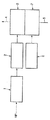
図1に示すような、本発明のヘリコプタのロータを駆動するパワーパックのパワーを調整するための装置は、ロータの回転速度に対応する入力信号NPを受信する電子制御装置1を備える。電子制御装置は、電子制御装置1から出力信号を受信し、燃料供給量を調整するための手段3を徐々に作動するアクチュエータ装置2にリンクしている。次に、この燃料は、参照番号4で概略示すダクトにより、ロータを駆動するパワーパックに送られる。燃料は、タンク(図示せず)から、参照番号5で概略示すダクトを通して供給される。アクチュエータ2により、調整手段3を通して、電子制御装置1から受信する信号により燃料供給量を徐々に増減することができる。
【0016】
電子制御装置1、及び調整手段3に関連するアクチュエータ装置2は、故障が発生した瞬間の燃料供給量を基準にして、燃料供給量を増やしたり、減らしたりする方法で、例えば、ターボエンジンのようなパワーパックへの燃料供給量を制御することができる、本発明の全緊急バックアップ装置を構成する。
【0017】
図1は、同様に、正常な動作中の、すなわち、故障が発生していない場合の、ターボエンジンへ燃料を供給している主調整システムの略図である。この場合、主調整システム6は、ダクト4を通してターボエンジンにヘリコプタの飛行条件の各瞬間に適応する燃料供給量で燃料を供給する主調整手段7に働きかける。
周知のように、主調整システムを使用することにより、飛行中に、ヘリコプタのロータの回転速度をほぼ一定に維持するために、エンジンが供給するパワーを調整することができる。本発明のパワー調整装置を使用すれば、パイロットは、特に面倒な手動による変更をしなくても、主調整システム6が故障した場合、主調整システム6が動作できない状況を補償することができる。
【0018】
図1の実施形態の場合には、燃料調整手段3は、主調整手段7から独立している。調整手段3は、燃料供給量を増やすために主調整手段7と並列に動作し、故障が発生した瞬間の燃料供給量に対して供給量を少なくするために、主調整手段7に対して直列に動作する。
【0019】
図2の実施形態の場合には、この場合も、電子制御装置1が、1つの入力信号としてロータの回転速度に対応する信号NPを受信する。電子装置1は、例えば、低域フィルタの形で濾過装置9の前に位置する、信号NPを取得するための手段8を備える。フィルタ9からの出力信号は、接続部10を通して微分回路素子11に送られ、接続部12を通して総和装置13に送られる。それ故、総和装置13からの出力信号はNP+K.dNP/dtとなる。この信号は、接続部14により、高いしきい値15aを持つコンパレータ素子、及び低いしきい値15bを持つコンパレータ素子を備える、しきい値をベースとするコンパレータ15に送られる。高いしきい値及び低いしきい値の各値は、接続部16a、16bを通してコンパレータ15a及び15bに送られる。
【0020】
それ故、しきい値をベースとするコンパレータ15は、信号NP+K.dNP/dtを高いしきい値及び低いしきい値と比較する。コンパレータ15は、アクチュエータ装置2を制御している電気的供給のための装置18にリンクしているその出力17a、17bの一方上に出力信号を送る。それ故、アクチュエータ2の制御はNP+K.dNP/dtが低いしきい値より低い場合には、燃料供給量を増やすように、NP+K.dNP/dtが高いしきい値より高い場合には、燃料供給量を減らすように、全か無かモードで行われる。コンパレータ15が信号を出力しない場合には、すなわち、信号NP+K.dNP/dtが高いしきい値と低いしきい値との間に位置している場合には、アクチュエータ2は動作しないで、燃料供給量は変化しない。
【0021】
それ故、本発明の装置は、信号NPの値を、所定の低いしきい値と所定の高いしきい値との間に維持するように動作し、その結果、ヘリコプタのロータの回転速度が、2つの同じように所定のしきい値の間に維持される。
微分項「K.dNP/dt」によるパワー要件の変動によりヘリコプタのロータの回転速度が変動し、そのため、信号NPが変動した場合は、すぐに、アクチュエータ装置2の制御を予測することができる。
【0022】
電気アクチュエータ装置2は、好適には、比較的遅い速度で移動することが好ましい。さらに、好適には、最低位置停止を備えることが好ましい。その場合には、すでに説明したように、低い値における燃料の供給量の変動速度に対する制限、及び燃料供給量の制限を行うことができ、そのため、運転中止を起こさないで、またポンピング及び減速を起こさないで、ターボエンジンを加速することができる。
電気アクチュエータ装置2としては、確実に比較的低速で運動する直流モータ又はステッパ・モータを使用することができる。
アクチュエータ装置2の電源用装置18は、一定速度の運動を制御することもできるし、又は信号NP又は運動の方向に従って運動の速度を制御することもできる。
【0023】
電気制御装置1全体は、いくつかの方法で製作することができる。それ故、演算増幅器を使用すれば、アナログ電子装置を構成することができる。また、EPLDタイプのプログラマブル・デジタル構成部材、ASICタイプの特別に開発された構成部材を使用することにより、又はソフトウェアにより制御されているマイクロプロセッサを使用することにより、いま説明した機能を入手することができる。
電子制御装置1は、調整の緊急バックアップ動作に対応する特殊ボックスに内蔵させることもできるし、逆に、ヘリコプタの他の機能を行うボックスに内蔵させることもできる。
【0024】
本発明の調整装置を使用すれば、低い生産オーバーヘッド・コストで、主調整システムが故障した場合に、緊急バックアップ・モードの動作を提供することができる。手動だけの緊急バックアップ装置と比較した場合、パイロットは、遥かに容易にまた安全に、本発明の装置を使用することができる。
【0025】
主調整システムが故障した場合には、本発明の装置は、ヘリコプタのロータの回転速度の単なる関数として、自動的に故障が発生した瞬間の供給量を基準にして、パワーパックへの燃料供給量の増減を命令する。それによる操縦の負担は、従来のタイプの手動緊急バックアップ装置を使用した場合の、操縦の負担と比較すると遥かに軽い。より詳細に説明すると、本発明の調整装置のお陰で、パイロットは、単に、ゆっくりと操縦し、ヘリコプタのエンジン及び飛行の両方に関連する動作制限に従うように注意しさえすればよい。燃料の供給量は、本発明の調整装置により自動的に制御される。
【0026】
ヘリコプタをどのように操縦した場合でも、燃料供給量を手動で変更しなければならない単発のヘリコプタの場合、操縦が、このように簡単になったということは特にメリットがある。
【0027】
それ故、本発明の装置を使用すれば、安全性が向上する。何故なら、パイロットが熟練していなくてもそれほど支障がないからである。さらに、本発明の装置のお陰で、緊急バックアップ・モードに対して、パイロットを特に訓練する必要がなくなり、それにより、オペレータはかなりの経済的利益を受ける。
【0028】
また、本発明の装置を使用すれば、信頼性、安全性、及び主調整システムの利用度に対する制限を軽減することができる。より詳細に説明すると、故障の場合に、信頼性が高く、容易に制御することができる緊急バックアップ・モードの動作を使用することができるので、主調整システムの許容できる故障率を高く設定することができる。
【0029】
本発明の装置は、手動だけの緊急バックアップ装置と比較した場合、パイロットが容易に使用できるという点で利便性が増すために、単発のヘリコプタに搭載されているターボエンジンに特に適している。さらに、この場合、本発明の装置を使用すれば、製造が面倒な回転ハンドル制御装置を必要とする手動緊急バックアップ装置の製造コストを安くすることができる。
【0030】
本発明の装置は、また、双発ヘリコプタに対しても使用することができる。この場合、他方のエンジンが緊急バックアップ・モード運転に切り替えられた場合に、正常に動作しているエンジンを自動的に調整できるように、2つのエンジンの間の負荷の、過度に大きなアンバランスを避ける必要がある場合がある。
本発明の装置は、入力、すなわち、ロータの回転速度として、1つのパラメータを使用しているために、また、必要な計算が簡単なために(速度信号及びその微分項の合計を所定の2つのしきい値と比較するだけ)、また、全又は無モードで、燃料供給量の増大、燃料供給量の低減、燃料供給量のそのままの維持を制御するために、1つの電気アクチュエータを使用しているために、非常に簡単な構造になっている。
【図面の簡単な説明】
【図1】 本発明の装置の一般的な原理を示す機能図である。
【図2】 本発明の装置の例示としての実施形態を示す機能図である。[0001]
The present invention relates to an apparatus for adjusting the power of a power pack that drives a helicopter rotor, and in particular during an emergency backup mode when the main system for adjusting the rotational speed of a helicopter rotor fails. The present invention relates to a device that can assist in the operation of a helicopter.
[0002]
The present invention also relates to an adjustment method used when the main adjustment system fails.
The helicopter turbo engine is equipped with a plurality of adjustment systems that perform several somewhat complex functions. However, the main function of this adjustment system is to adjust the power supplied by the turbo engine in order to keep the rotational speed of the helicopter rotor substantially constant during flight.
[0003]
The adjustment system currently in active use is an electronic adjustment system with a manual emergency backup device.
[0004]
During normal operation, adjustments are managed by an electronic computer that controls the various actuators to receive signals from the various sensors and automatically adjust the power supplied by the engine. In the event of a failure that affects the electronic regulation system and prevents the computer from adjusting the power supplied by the engine, the helicopter pilot can manually maneuver the helicopter with a manual emergency backup device. Setting, pitch reduction, landing, etc.), the power supplied by the turbo engine must be changed as a function of the requirements generated. This makes it very difficult to control the helicopter. More specifically, the pilot must manually adjust the amount of fuel delivered to the turbo engine at each instant. Such adjustment is particularly difficult in the case of a single-shot helicopter, and the fuel supply amount must be changed manually one by one in order to perform all operations of the helicopter.
[0005]
Therefore, pilots need to be specifically trained to handle this special situation. However, in order to reduce the risk that can arise from improper training of pilots, turbo engine manufacturers tend to try to make the main adjustment system failure rate extremely low, which makes the system more complex As a result, the cost of the entire adjustment system increases.
[0006]
It is an object of the present invention to provide a simple and low cost device that can improve power pack power adjustment in the event of a failure of the main adjustment system and facilitate maneuvering in emergency backup mode. is there.
Another object of the present invention is to provide an adjusting device that is highly safe in the event of a failure and that is relatively inexpensive to produce.
[0007]
An apparatus for adjusting the power of a power pack that drives a rotor of a helicopter according to the present invention is a means for adjusting a fuel supply amount and an input signal (NP) corresponding to the rotational speed of the rotor. An electronic control device comprising means, means for processing the input signal comprising a differentiating circuit element and a summation device element, and a threshold-based comparator for receiving an output signal from the processing means. . The actuator device receives an output signal from the electronic control unit and gradually adjusts the fuel supply amount to increase the supply amount, to reduce the supply amount, or to maintain the supply amount as it is. Operates on.
[0008]
Since no manual control is used, there are no levers, linkages, bell cranks, etc., so such a device is particularly simple and can be easily installed and used. If the main adjustment system fails, the helicopter pilot no longer needs to manually control the fuel supply. The fuel supply amount is automatically controlled.
[0009]
Helicopter maneuvering when the main adjustment system fails is very simple compared to emergency backup maneuvers where the power is changed manually. This is because the pilot only needs to avoid abrupt maneuvers and maneuver slowly and observe the maximum engine ratings and helicopter rotor torque and speed limitations. Pilots no longer have to worry about fuel supply. This is because the fuel supply amount is automatically controlled by the apparatus of the present invention. In more detail, the pilot no longer manually adjusts the fuel supply at each moment to accommodate the power requirements generated by helicopter maneuvers, such as pitch setting, pitch reduction, landing, etc. There is no need to change.
[0010]
In a preferred embodiment, the actuator device is an electronic device, the electronic control device further comprising an electrical supply means for the actuator device.
A low-pass filter can be installed for filtering the input signal.
The comparator preferably has a predetermined higher threshold value and a predetermined lower threshold value.
[0011]
The actuator device preferably operates at a relatively low speed and preferably includes a lowest position stop. Then, the signal integration effect is automatically obtained. Furthermore, if the fluctuation speed of the fuel supply amount thereby is limited, the engine can be accelerated without any risk of pumping. Similarly, the engine can be decelerated without stopping operation by stopping at the lowest position.
As the actuator device, for example, a DC motor or a stepper motor whose rotation speed is constant at a specified supply voltage can be used.
[0012]
The means for adjusting the fuel supply amount may comprise a fuel auxiliary adjustment device operating in cooperation with the main adjustment device. The auxiliary adjustment device operates in parallel with the main adjustment device in order to add a slight supply amount to the supply amount at the moment of failure, and operates in series with the main adjustment device in order to reduce the supply amount slightly. To explain another example, a single adjusting member controlled by a stepper motor having two inputs can be used as the adjusting device. In this case, one input is actuated by the main regulating system and the other input is actuated by the device of the present invention in the event that the main regulating system fails.
[0013]
The present invention is particularly suitable when the power pack is a turbo engine.
The present invention also relates to a method for adjusting the power of the power pack that drives the rotor of the helicopter in the more general manner if the main adjustment system fails. In this case, the increase / decrease in the fuel supply amount to the power pack is automatically controlled as a function (NP) of the rotational speed of the rotor with reference to the supply amount at the moment of failure.
When used as one input signal for the rotational speed of the rotor, the method of the invention can be carried out very simply and at low cost.
[0014]
The invention may be better understood by reference to the specific embodiments shown by way of example and shown in the accompanying drawings.
[0015]
The apparatus for adjusting the power of the power pack that drives the rotor of the helicopter of the present invention as shown in FIG. 1 includes an electronic control unit 1 that receives an input signal NP corresponding to the rotational speed of the rotor. The electronic control device receives the output signal from the electronic control device 1 and is linked to the actuator device 2 which gradually operates the
[0016]
The electronic control device 1 and the actuator device 2 related to the adjusting means 3 are a method of increasing or decreasing the fuel supply amount on the basis of the fuel supply amount at the moment when the failure occurs, such as a turbo engine. All the emergency backup devices of the present invention which can control the amount of fuel supplied to the power pack are configured.
[0017]
FIG. 1 is also a schematic diagram of a main regulating system supplying fuel to a turbo engine during normal operation, ie when no failure has occurred. In this case, the main adjustment system 6 acts on the main adjustment means 7 that supplies fuel to the turbo engine through the duct 4 at a fuel supply amount that adapts to each moment of flight conditions of the helicopter.
As is well known, by using the main adjustment system, the power supplied by the engine can be adjusted during flight to maintain the helicopter rotor rotational speed approximately constant. By using the power adjustment device of the present invention, the pilot can compensate for a situation in which the main adjustment system 6 cannot operate when the main adjustment system 6 fails without particularly troublesome manual changes.
[0018]
In the case of the embodiment of FIG. 1, the fuel adjustment means 3 is independent of the main adjustment means 7. The adjusting means 3 operates in parallel with the main adjusting means 7 in order to increase the fuel supply amount, and in series with the main adjusting means 7 in order to reduce the supply amount with respect to the fuel supply amount at the moment when the failure occurs. To work.
[0019]
In the case of the embodiment of FIG. 2, the electronic control unit 1 also receives a signal NP corresponding to the rotational speed of the rotor as one input signal. The electronic device 1 comprises
[0020]
Therefore, the threshold-based
[0021]
Therefore, the device of the present invention operates to maintain the value of the signal NP between a predetermined low threshold and a predetermined high threshold so that the rotational speed of the helicopter rotor is It is maintained between two similarly predetermined thresholds.
The rotation speed of the rotor of the helicopter fluctuates due to the fluctuation of the power requirement due to the differential term “K.dNP/dt”. Therefore, when the signal NP fluctuates, the control of the actuator device 2 can be predicted immediately.
[0022]
The electric actuator device 2 is preferably moved at a relatively slow speed. Furthermore, it is preferable to provide a minimum position stop. In that case, as already explained, it is possible to limit the fluctuation rate of the fuel supply amount at a low value and to limit the fuel supply amount, so that the pumping and deceleration can be performed without stopping the operation. The turbo engine can be accelerated without waking up.
As the electric actuator device 2, a direct current motor or a stepper motor that reliably moves at a relatively low speed can be used.
The
[0023]
The entire electric control device 1 can be manufactured in several ways. Therefore, if an operational amplifier is used, an analog electronic device can be constructed. Obtain the functions just described by using programmable digital components of the EPLD type, specially developed components of the ASIC type, or by using a microprocessor controlled by software. Can do.
The electronic control device 1 can be built in a special box corresponding to the emergency backup operation for adjustment, or conversely, can be built in a box that performs other functions of the helicopter.
[0024]
With the adjustment device of the present invention, it is possible to provide emergency backup mode operation in the event of a failure of the main adjustment system at low production overhead costs. Compared to a manual emergency backup device, the pilot can use the device of the present invention much more easily and safely.
[0025]
In the event of a failure of the main adjustment system, the device according to the present invention provides a fuel supply to the power pack as a function of the rotational speed of the helicopter rotor, based on the supply at the moment of the automatic failure. Command to increase or decrease. The maneuvering burden is much lighter than the maneuvering burden when using a conventional type of manual emergency backup device. In more detail, thanks to the adjustment device of the present invention, the pilot need only be careful to maneuver slowly and to comply with the operational limitations associated with both the helicopter engine and flight. The amount of fuel supplied is automatically controlled by the adjusting device of the present invention.
[0026]
Regardless of how the helicopter is maneuvered, the fact that maneuvering is so simple is particularly advantageous in the case of a single shot helicopter where the fuel supply must be changed manually.
[0027]
Therefore, safety is improved by using the apparatus of the present invention. This is because there is no problem even if the pilot is not skilled. Furthermore, thanks to the device according to the invention, it is not necessary to train the pilot specifically for the emergency backup mode, so that the operator receives considerable economic benefits.
[0028]
In addition, the use of the apparatus of the present invention can alleviate limitations on reliability, safety, and utilization of the main adjustment system. More specifically, in the event of a failure, it is possible to use an emergency backup mode operation that is reliable and easily controllable, so the failure rate of the main adjustment system should be set high. Can do.
[0029]
The device of the present invention is particularly suitable for a turbo engine mounted on a single helicopter because it is more convenient in that the pilot can be easily used when compared to a manual emergency backup device. Furthermore, in this case, if the device of the present invention is used, the manufacturing cost of the manual emergency backup device that requires a troublesome rotating handle control device can be reduced.
[0030]
The device of the present invention can also be used for twin-engine helicopters. In this case, if the other engine is switched to emergency backup mode operation, an excessively large unbalance in the load between the two engines can be adjusted so that the engine operating normally can be adjusted automatically. You may need to avoid it.
The apparatus of the present invention uses a single parameter as the input, i.e., the rotational speed of the rotor, and because of the simplicity of the calculations required (the sum of the speed signal and its derivative term is a predetermined 2). One electric actuator to control the increase of fuel supply, the decrease of fuel supply, and the maintenance of the fuel supply as it is, in all or no mode. Therefore, it has a very simple structure.
[Brief description of the drawings]
FIG. 1 is a functional diagram showing the general principle of the device of the present invention.
FIG. 2 is a functional diagram illustrating an exemplary embodiment of the apparatus of the present invention.
Claims (10)
Applications Claiming Priority (3)
| Application Number | Priority Date | Filing Date | Title |
|---|---|---|---|
| FR99/16392 | 1999-12-23 | ||
| FR9916392A FR2803051B1 (en) | 1999-12-23 | 1999-12-23 | DEVICE AND METHOD FOR CONTROLLING THE POWER OF A HELICOPTER ROTOR DRIVE DRIVE UNIT |
| PCT/FR2000/003571 WO2001048574A2 (en) | 1999-12-23 | 2000-12-18 | Device and method for adjusting the power of a power pack driving a helicopter rotor |
Publications (2)
| Publication Number | Publication Date |
|---|---|
| JP2003518590A JP2003518590A (en) | 2003-06-10 |
| JP4837863B2 true JP4837863B2 (en) | 2011-12-14 |
Family
ID=9553760
Family Applications (1)
| Application Number | Title | Priority Date | Filing Date |
|---|---|---|---|
| JP2001549160A Expired - Lifetime JP4837863B2 (en) | 1999-12-23 | 2000-12-18 | Apparatus and method for adjusting the power of a power pack that drives a helicopter rotor |
Country Status (12)
| Country | Link |
|---|---|
| US (1) | US6729138B2 (en) |
| EP (1) | EP1240417B1 (en) |
| JP (1) | JP4837863B2 (en) |
| KR (1) | KR100721984B1 (en) |
| CN (1) | CN1199005C (en) |
| AU (1) | AU2528001A (en) |
| CA (1) | CA2395307C (en) |
| FR (1) | FR2803051B1 (en) |
| PL (1) | PL198210B1 (en) |
| RU (1) | RU2267020C2 (en) |
| WO (1) | WO2001048574A2 (en) |
| ZA (1) | ZA200204530B (en) |
Families Citing this family (21)
| Publication number | Priority date | Publication date | Assignee | Title |
|---|---|---|---|---|
| FR2827636B1 (en) * | 2001-07-19 | 2003-11-28 | Eurocopter France | SYSTEM FOR REGULATING THE SPEED OF A HELICOPTER ENGINE |
| EP2113922B1 (en) | 2004-03-26 | 2010-09-01 | LG Electronics Inc. | Recording medium and method and apparatus for reproducing and recording text subtitle streams |
| FR2878288B1 (en) * | 2004-11-25 | 2007-01-19 | Eurocopter France | METHOD AND DEVICE FOR OPTIMIZING THE PERFORMANCE ENVELOPE OF A TURBOMOTEUR |
| FR2899640B1 (en) * | 2006-04-05 | 2011-11-25 | Eurocopter France | METHOD AND DEVICE FOR REALIZING A HEALTH CONTROL OF A TURBOMOTOR OF A BIMOTING GIRROR |
| US7931231B2 (en) * | 2007-05-18 | 2011-04-26 | Sikorsky Aircraft Corporation | Engine anticipation for rotary-wing aircraft |
| US8881764B2 (en) | 2008-05-13 | 2014-11-11 | Sikorsky Aircraft Corporation | Offset ambient level fuel feed system |
| WO2010056241A1 (en) | 2008-11-13 | 2010-05-20 | Sikorsky Aircraft Corporation | Adaptive fail-fixed system for fadec controlled gas turbine engines |
| ITTO20090079U1 (en) * | 2009-06-10 | 2010-12-11 | Agusta Spa | SYSTEM FOR THE MANAGEMENT AND CONTROL OF THE SPEED OF ONE OR MORE ROTORS OF AN AIRCRAFT SUITABLE FOR FLYING AT A FIXED POINT |
| RU2444464C2 (en) * | 2010-01-11 | 2012-03-10 | Открытое акционерное общество "СТАР" | Method of controlling helicopter power plant |
| RU2452667C2 (en) * | 2010-05-24 | 2012-06-10 | Открытое акционерное общество "СТАР" | Method of controlling helicopter power plant |
| US8996204B2 (en) * | 2010-06-23 | 2015-03-31 | Honeywell International Inc. | Systems and methods for adjusting target approach speed |
| FR2967132B1 (en) * | 2010-11-04 | 2012-11-09 | Turbomeca | METHOD OF OPTIMIZING THE SPECIFIC CONSUMPTION OF A BIMOTING HELICOPTER AND DISSYMMETRIC BIMOTOR ARCHITECTURE WITH A CONTROL SYSTEM FOR ITS IMPLEMENTATION |
| RU2482024C2 (en) * | 2010-12-29 | 2013-05-20 | Открытое акционерное общество "СТАР" | Method of helicopter power plant control |
| US9856017B2 (en) * | 2013-06-11 | 2018-01-02 | Bell Helicopter Textron Inc. | Torque based method of limiting vertical axis augmentation |
| FR3011587B1 (en) * | 2013-10-09 | 2015-11-06 | Turbomeca | METHOD OF OPTIMIZING THE SPECIFIC CONSUMPTION OF A BIMOTING HELICOPTER |
| FR3018098B1 (en) * | 2014-02-28 | 2019-04-05 | Safran Helicopter Engines | FUEL SUPPLY CONTROL SYSTEM IN A HELICOPTER TURBOMACHINE |
| FR3026438B1 (en) * | 2014-09-26 | 2019-03-15 | Airbus Helicopters | METHOD FOR STOPPING AN OVERSPEED RUNNING MOTOR, SYSTEM AND GIRAVION THEREFOR |
| US10691552B2 (en) * | 2015-10-12 | 2020-06-23 | International Business Machines Corporation | Data protection and recovery system |
| FR3089247B1 (en) * | 2018-11-30 | 2020-12-18 | Airbus Helicopters | Method and system for stopping a gas turbine and vehicle |
| FR3090576B1 (en) * | 2018-12-20 | 2021-09-10 | Airbus Helicopters | Assistance method for single-engine rotary-wing aircraft during engine failure. |
| FR3111668B1 (en) * | 2020-06-17 | 2023-04-07 | Airbus Helicopters | Method for shutting down an overspeeding engine, associated system and rotorcraft |
Citations (6)
| Publication number | Priority date | Publication date | Assignee | Title |
|---|---|---|---|---|
| JPS58190528A (en) * | 1982-04-16 | 1983-11-07 | ユナイテツド・テクノロジ−ズ・コ−ポレイシヨン | Engine control apparatus for free turbine gas engine |
| JPS58191696A (en) * | 1982-04-16 | 1983-11-08 | ユナイテツド・テクノロジ−ズ・コ−ポレイシヨン | Helicopter |
| US4648797A (en) * | 1983-12-19 | 1987-03-10 | United Technologies Corporation | Torque control system |
| US5046923A (en) * | 1989-10-02 | 1991-09-10 | United Technologies Corporation | Helicopter autorotation detection and recovery |
| US5775089A (en) * | 1996-12-23 | 1998-07-07 | Allison Engine Company | Pressure signal synthesis method and system for a gas turbine engine |
| US5812428A (en) * | 1995-09-22 | 1998-09-22 | Rosemount Inc. | Process controller having non-integrating control function and adaptive bias |
Family Cites Families (4)
| Publication number | Priority date | Publication date | Assignee | Title |
|---|---|---|---|---|
| US5029441A (en) * | 1989-09-20 | 1991-07-09 | United Technologies Corporation | Dynamic compensation to n-dot schedules |
| GB9000176D0 (en) * | 1990-01-04 | 1990-03-07 | Lucas Ind Plc | Fuel control system for helicopter engine |
| US5490379A (en) * | 1993-12-20 | 1996-02-13 | Woodward Governor Company | Fuel metering unit |
| US5509265A (en) * | 1995-01-23 | 1996-04-23 | Alliedsignal Inc. | Operational signal stability means for turbine |
-
1999
- 1999-12-23 FR FR9916392A patent/FR2803051B1/en not_active Expired - Lifetime
-
2000
- 2000-12-18 KR KR1020027007938A patent/KR100721984B1/en active IP Right Grant
- 2000-12-18 CN CNB008177449A patent/CN1199005C/en not_active Expired - Lifetime
- 2000-12-18 PL PL356701A patent/PL198210B1/en unknown
- 2000-12-18 JP JP2001549160A patent/JP4837863B2/en not_active Expired - Lifetime
- 2000-12-18 RU RU2002119582/28A patent/RU2267020C2/en active
- 2000-12-18 WO PCT/FR2000/003571 patent/WO2001048574A2/en active IP Right Grant
- 2000-12-18 CA CA2395307A patent/CA2395307C/en not_active Expired - Lifetime
- 2000-12-18 US US10/149,964 patent/US6729138B2/en not_active Expired - Lifetime
- 2000-12-18 AU AU25280/01A patent/AU2528001A/en not_active Abandoned
- 2000-12-18 EP EP00988946A patent/EP1240417B1/en not_active Expired - Lifetime
-
2002
- 2002-06-06 ZA ZA200204530A patent/ZA200204530B/en unknown
Patent Citations (6)
| Publication number | Priority date | Publication date | Assignee | Title |
|---|---|---|---|---|
| JPS58190528A (en) * | 1982-04-16 | 1983-11-07 | ユナイテツド・テクノロジ−ズ・コ−ポレイシヨン | Engine control apparatus for free turbine gas engine |
| JPS58191696A (en) * | 1982-04-16 | 1983-11-08 | ユナイテツド・テクノロジ−ズ・コ−ポレイシヨン | Helicopter |
| US4648797A (en) * | 1983-12-19 | 1987-03-10 | United Technologies Corporation | Torque control system |
| US5046923A (en) * | 1989-10-02 | 1991-09-10 | United Technologies Corporation | Helicopter autorotation detection and recovery |
| US5812428A (en) * | 1995-09-22 | 1998-09-22 | Rosemount Inc. | Process controller having non-integrating control function and adaptive bias |
| US5775089A (en) * | 1996-12-23 | 1998-07-07 | Allison Engine Company | Pressure signal synthesis method and system for a gas turbine engine |
Also Published As
| Publication number | Publication date |
|---|---|
| KR20020088064A (en) | 2002-11-25 |
| WO2001048574A2 (en) | 2001-07-05 |
| PL198210B1 (en) | 2008-06-30 |
| AU2528001A (en) | 2001-07-09 |
| CA2395307A1 (en) | 2001-07-05 |
| CN1199005C (en) | 2005-04-27 |
| CA2395307C (en) | 2010-05-11 |
| CN1413289A (en) | 2003-04-23 |
| US20030059303A1 (en) | 2003-03-27 |
| ZA200204530B (en) | 2004-03-01 |
| FR2803051A1 (en) | 2001-06-29 |
| JP2003518590A (en) | 2003-06-10 |
| EP1240417A2 (en) | 2002-09-18 |
| WO2001048574A3 (en) | 2002-02-14 |
| PL356701A1 (en) | 2004-06-28 |
| RU2267020C2 (en) | 2005-12-27 |
| KR100721984B1 (en) | 2007-05-25 |
| US6729138B2 (en) | 2004-05-04 |
| EP1240417B1 (en) | 2006-03-08 |
| FR2803051B1 (en) | 2002-05-03 |
Similar Documents
| Publication | Publication Date | Title |
|---|---|---|
| JP4837863B2 (en) | Apparatus and method for adjusting the power of a power pack that drives a helicopter rotor | |
| US11027854B2 (en) | Precision operator for an aircraft autothrottle or autopilot system with engine performance adjust | |
| EP2132089B1 (en) | Governor for a rotor with a variable maximum collective pitch and method | |
| US10633105B2 (en) | Precision operator for an aircraft autothrottle or autopilot system with engine performance adjust | |
| US10106268B2 (en) | Method of regulating a three-engined power plant for a rotary wing aircraft | |
| EP0093684B1 (en) | Helicopter engine control with rotor speed decay anticipator | |
| US20020171005A1 (en) | Device and process for regulating the power of the engines of a rotary wing multi-engine aircraft | |
| CN111936385B (en) | System and method for propeller response enhancement during transition of a turboprop from a ground configuration to a flight configuration | |
| EP3693573A1 (en) | System and method for controlling propeller-driven aircraft | |
| EP3936712A1 (en) | Hybrid electric powerplant (hep) control architecture | |
| JPH03105029A (en) | Helicopter controler with a plurality of schedules, predicting reduction of rotter speed | |
| US6792338B2 (en) | System and method for actively limiting the power drawn from a power distribution bus | |
| US9849997B2 (en) | Method for synchronising the engines of an airplane with dual intermediate state | |
| EP3670348A1 (en) | Device for providing power or thrust to an aerospace vehicle and method for controlling a device for providing power to an aerospace vehicle | |
| EP3383738B1 (en) | Method for dynamic command limiting in a distributed control system | |
| JP7439274B2 (en) | Hybrid drive system for helicopters | |
| JPH0414650Y2 (en) | ||
| JPH09184431A (en) | Rotational speed control method of lengthy rotary vane and rotational speed control device | |
| JPS6394058A (en) | Control method for engine |
Legal Events
| Date | Code | Title | Description |
|---|---|---|---|
| A621 | Written request for application examination |
Free format text: JAPANESE INTERMEDIATE CODE: A621 Effective date: 20071026 |
|
| A131 | Notification of reasons for refusal |
Free format text: JAPANESE INTERMEDIATE CODE: A131 Effective date: 20091204 |
|
| A601 | Written request for extension of time |
Free format text: JAPANESE INTERMEDIATE CODE: A601 Effective date: 20100304 |
|
| A602 | Written permission of extension of time |
Free format text: JAPANESE INTERMEDIATE CODE: A602 Effective date: 20100311 |
|
| A601 | Written request for extension of time |
Free format text: JAPANESE INTERMEDIATE CODE: A601 Effective date: 20100402 |
|
| A602 | Written permission of extension of time |
Free format text: JAPANESE INTERMEDIATE CODE: A602 Effective date: 20100409 |
|
| A601 | Written request for extension of time |
Free format text: JAPANESE INTERMEDIATE CODE: A601 Effective date: 20100430 |
|
| A602 | Written permission of extension of time |
Free format text: JAPANESE INTERMEDIATE CODE: A602 Effective date: 20100512 |
|
| A521 | Written amendment |
Free format text: JAPANESE INTERMEDIATE CODE: A523 Effective date: 20100531 |
|
| A131 | Notification of reasons for refusal |
Free format text: JAPANESE INTERMEDIATE CODE: A131 Effective date: 20101029 |
|
| A02 | Decision of refusal |
Free format text: JAPANESE INTERMEDIATE CODE: A02 Effective date: 20110422 |
|
| A521 | Written amendment |
Free format text: JAPANESE INTERMEDIATE CODE: A523 Effective date: 20110719 |
|
| A911 | Transfer to examiner for re-examination before appeal (zenchi) |
Free format text: JAPANESE INTERMEDIATE CODE: A911 Effective date: 20110726 |
|
| TRDD | Decision of grant or rejection written | ||
| A01 | Written decision to grant a patent or to grant a registration (utility model) |
Free format text: JAPANESE INTERMEDIATE CODE: A01 Effective date: 20110920 |
|
| A01 | Written decision to grant a patent or to grant a registration (utility model) |
Free format text: JAPANESE INTERMEDIATE CODE: A01 |
|
| A61 | First payment of annual fees (during grant procedure) |
Free format text: JAPANESE INTERMEDIATE CODE: A61 Effective date: 20110929 |
|
| FPAY | Renewal fee payment (event date is renewal date of database) |
Free format text: PAYMENT UNTIL: 20141007 Year of fee payment: 3 |
|
| R150 | Certificate of patent or registration of utility model |
Ref document number: 4837863 Country of ref document: JP Free format text: JAPANESE INTERMEDIATE CODE: R150 Free format text: JAPANESE INTERMEDIATE CODE: R150 |
|
| R250 | Receipt of annual fees |
Free format text: JAPANESE INTERMEDIATE CODE: R250 |
|
| R250 | Receipt of annual fees |
Free format text: JAPANESE INTERMEDIATE CODE: R250 |
|
| R250 | Receipt of annual fees |
Free format text: JAPANESE INTERMEDIATE CODE: R250 |
|
| R250 | Receipt of annual fees |
Free format text: JAPANESE INTERMEDIATE CODE: R250 |
|
| R250 | Receipt of annual fees |
Free format text: JAPANESE INTERMEDIATE CODE: R250 |
|
| R250 | Receipt of annual fees |
Free format text: JAPANESE INTERMEDIATE CODE: R250 |
|
| R250 | Receipt of annual fees |
Free format text: JAPANESE INTERMEDIATE CODE: R250 |
|
| EXPY | Cancellation because of completion of term |