JP4765178B2 - Three-phase switch - Google Patents
Three-phase switch Download PDFInfo
- Publication number
- JP4765178B2 JP4765178B2 JP2001056810A JP2001056810A JP4765178B2 JP 4765178 B2 JP4765178 B2 JP 4765178B2 JP 2001056810 A JP2001056810 A JP 2001056810A JP 2001056810 A JP2001056810 A JP 2001056810A JP 4765178 B2 JP4765178 B2 JP 4765178B2
- Authority
- JP
- Japan
- Prior art keywords
- phase
- opening
- switch
- predetermined time
- shut
- Prior art date
- Legal status (The legal status is an assumption and is not a legal conclusion. Google has not performed a legal analysis and makes no representation as to the accuracy of the status listed.)
- Expired - Fee Related
Links
Images


Landscapes
- Driving Mechanisms And Operating Circuits Of Arc-Extinguishing High-Tension Switches (AREA)
- Keying Circuit Devices (AREA)
- Control Of Voltage And Current In General (AREA)
Description
【0001】
【発明の属する技術分野】
この発明は電源に変圧器を投入・遮断する三相開閉器の改良に関し、特に、三相変圧器の励磁突入電流を低減させる三相開閉器に関するものである。
【0002】
【従来の技術】
従来の三相開閉器が適用される変電装置を図4によって説明する。図4において、変電装置1は、三相交流電源3に接続されると共に、スイッチS1,S2,S3を同時に投入及び遮断させる三相開閉器5と、該スイッチS1,S2,S3に接続された各端子t1,t2,t3を有する共に、△結線された三相変圧器7とから成っている。
【0003】
上記のように構成された変電装置において、三相開閉器5のスイッチS1,S2,S3を同時投入して三相変圧器7に三相交流電源3の電圧を印加する時、三相変圧器7の残留磁束などによって異なるが、定格電流の数十倍の励磁突入電流が流れ、時間の経過と共に減衰して定常状態になることが知られている。
【0004】
励磁突入電流の最大値I0maxは、電源電圧の瞬時値がゼロの時に投入され、かつ、三相変圧器7の鉄心内の残留磁束と電圧投入直後の磁束の方向とが一致した場合に最大となり下式となる。
I0max=K・(2Bm+Br−BS)・・・・・(1)
ここに、K:比例定数, Bm:定常状態磁束密度(T)
Br:残留磁束密度(T), BS:飽和磁束密度(T)
ここで、飽和磁束密度BSは一般に2テスラ程度が採用されているので、前記(1)式は下式となる。
I0max=K・(2Bm+Br−2)・・・・・(2)
励磁突入電流は、保護装置の誤動作などを生じさせるので、低減対策が図られており、励磁突入電流を減少させるには、前記(2)式より定常状態磁束密度Bm、残留磁束密度Brの低減手段がある。
【0005】
【発明が解決しようとする課題】
しかしながら、定常状態磁束密度Bmを例えば半分にすると、三相変圧器7の鉄心の断面積が2倍になり、該鉄心の外周に巻回されたコイル、コイル等を収納させるタンクなども大型化し、三相変圧器7が大型化すると共に、所定の変圧器特性が得にくいという問題点があった。
【0006】
また、残留磁束密度Brを低減するには、三相変圧器7の鉄心に突き合わせ接合部を設ければ良いが、該接合部のギャップに大きな振動性の力が作用することにより騒音が発生し、しかも、該振動性の力に耐えるために、一般変圧器に比べて極めて強固な鉄心締め付け構造を有する三相変圧器にしなければならないという問題点があった。
【0007】
この発明は、前記問題点を解決するためになされたもので、所謂標準変圧器を三相交流電源へ投入・遮断するタイミングを適切に実行することで、励磁突入電流を減少させる三相開閉器を提供することを目的としている。
【0008】
【課題を解決するための手段、発明の作用及び効果】
第1の発明に係る三相開閉器は、第1から第3の端子を有すると共に、上記第1と第2の端子間に接続された第1相、上記第2と第3の端子間に接続された第2相、上記第1と第3の端子間に接続された第3相を備えた三相変圧器の上記第1から第3の端子に電圧を投入及び遮断するためにそれぞれに接続される第1から第3の開閉部を有すると共に、三相交流電源に接続される三相開閉器であって、上記第1から第3の開閉部が投入された状態において、上記開閉部の遮断指令に基づき上記第1の開閉部を遮断した後に、上記遮断指令から第1の所定の時間後に上記第2の開閉部を遮断すると共に、上記遮断指令から第2の所定時間後に上記第3の開閉部を遮断する遮断制御手段と、上記三相変圧器の第2相が、上記第1相又は上記第3相よりも第3の所定時間遅れて上記三相交流電源を上記第1から上記第3の端子に投入されるように上記開閉部の投入指令に基づいて上記第1から第3の開閉部を投入する投入制御手段と、を備え、上記第1の所定時間および第2の所定時間は、上記三相交流電源の周波数の1周期以上であることを特徴とするものである。
ここで、第1の所定時間は、第2の所定時間よりも長くても短くても良い。かかる三相開閉器によれば、三相変圧器が励磁されている状態において第2及び第3の開閉部よりも先に、第1の開閉部を遮断することにより三相のうち、二つの相の残留磁束を減少させた後、第2の開閉部、第3の開閉部を所定時間後に遮断して三相変圧器を三相交流電源から遮断する。三相変圧器を励磁する時には、前記残留磁束の大きい第2相が、第1相又は第3相よりも第3の所定時間遅れて開閉部を投入して三相変圧器のすべての相に電圧を印加する。したがって、残留磁束密度が減少した三相変圧器の一相に最初に電源投入することにより励磁突入電流が減少するので、一般変圧器を用いながら励磁突入電流を減少させることができるという効果がある。
【0009】
第2の発明に係る三相開閉器は、三相変圧器に接続される第1から第3の開閉部を有すると共に、三相交流電源に接続される三相開閉器であって、上記第1から第3の開閉部が投入された状態において、上記開閉部の遮断指令に基づき上記第1の開閉部を遮断した後に、上記遮断指令から第1の所定の時間後に上記第2の開閉部を遮断すると共に、上記遮断指令から第2の所定時間後に上記第3の開閉部を遮断する遮断制御手段と、上記開閉部の投入指令に基づき上記第1の開閉部を投入後に、上記投入指令の発生から第3の所定時間後に上記第2の開閉部を投入すると共に、上記投入指令の発生から上記第3の所定時間と異なる第4の所定時間後に上記第3の開閉部を投入する投入制御手段と、を備え、上記第1から第4の所定時間は、上記三相交流電源の周波数の1周期以上であることを特徴とするものである。
ここで、第3の所定時間は、第4の所定時間よりも長くても短くても良い。かかる三相開閉器によれば、三相変圧器が励磁されている状態において第2及び第3の開閉部よりも先に、第1の開閉部を遮断することにより三相のうち、二つの相の残留磁束を減少させた後、第2の開閉部、第3の開閉部を所定時間後に遮断して三相変圧器を三相交流電源から遮断する。三相変圧器を励磁する時には、最初に第1の開閉部を投入した後、例えば第3の所定時間後に第2開閉部を投入して前記残留磁束の少ない一相に三相交流電源の単相電圧を印加した後、第3の開閉部を投入して三相交流電圧を三相変圧器に印加する。したがって、残留磁束密度が減少した三相変圧器の一相に最初に電源投入することにより励磁突入電流が減少するので、一般変圧器を用いながら励磁突入電流を減少させることができるという効果がある。
【0010】
第3の発明に係る三相開閉器は、三相変圧器に接続される第1から第3の開閉部を有すると共に、三相交流電源に接続される三相開閉器であって、上記第1から第3の開閉部が投入された状態において、上記開閉部の遮断指令に基づき上記第1の開閉部を遮断した後に、上記遮断指令から第1の所定の時間後に上記第2の開閉部を遮断すると共に、上記遮断指令から第2の所定時間後に上記第3の開閉部を遮断する遮断制御手段と、上記開閉部の投入指令に基づき上記第1の開閉部と、上記第2又は第3の開閉部とを投入後、上記投入指令の発生から第3の所定時間後に投入されていない上記第3又は第2の開閉部を投入する投入制御手段とを備え、上記第1から第3の所定時間は、上記三相交流電源の周波数の1周期以上であることを特徴とするものである。
かかる三相開閉器によれば、三相変圧器が励磁されている状態において第2及び第3の開閉部よりも先に、第1の開閉部を遮断することにより三相のうち、二つの相の残留磁束を減少させた後、第2の開閉部、第3の開閉部を所定時間後に遮断して三相変圧器を三相交流電源から遮断する。三相変圧器を励磁する時には、前記残留磁束の少ない一相に、第1の開閉部と、第2又は第3の開閉部とにより最初に電源電圧を印加した後、投入されていない第3又は第2の開閉部を投入して三相変圧器のすべての相に電圧を印加する。したがって、残留磁束密度が減少した三相変圧器の一相に最初に電源投入することにより励磁突入電流が減少するので、一般変圧器を用いながら励磁突入電流を減少させることができるという効果がある。
【0011】
第4の発明に係る三相開閉器は、第1又は第2の発明において第1及び第2の所定時間が同一である、ことを特徴とするものである。
かかる三相開閉器によれば、第1の開閉部を遮断した後、同一の所定時間後に第2及び第3の開閉部を遮断したので、速やかに三相変圧器を三相交流電源から遮断できるという効果がある。
【0012】
第1乃至第4の発明に係る三相開閉器の何れかにおいて、第1から第4の所定時間が三相交流電源の周波数の1周期以上である、ことを特徴とするものである。かかる三相開閉器によれば、第1から第4の所定時間が三相交流電源の周波数の1周期以上であるので、三相変圧器の各相の磁束が確立されてから、次の開閉部を投入又は遮断できるので、励磁突入電流を確実に減少できるという効果がある。
【0013】
【発明の実施の形態】
実施の形態1.
この発明の一実施の形態を図1及び図2によって説明する。 図1は一実施の形態による変電装置の接続図、図2は、図1に示す三相開閉器及び鉄心とコイルとから成る三相変圧器の接続図であり、以下に三相開閉器を変電装置に適用した実施の形態を説明する。
図1及び図2において、変電装置1は、三相交流電源3を開閉部としてのスイッチS1,S2,S3を独立して投入(閉成)及び遮断(開放)させる三相開閉器100を介して△結線された三相変圧器7の第1の端子t1,第2の端子t2,第3の端子t3に接続されており、三相開閉器100には、第1の開閉部としての第1のスイッチS1,第2の開閉部としての第2のスイッチS2,第3の開閉部としての第3スイッチS3を独立して開閉を制御する制御部105が接続されている。
また、三相変圧器7には、端子t1,t2間に第1相となるU相、端子t2,t3間に第2相となるV相、端子t1,t3間に第3相となるW相の各コイルが接続され、U相を形成する右端の鉄心脚7a、V相を形成する中央の鉄心脚7b、W相を形成する左端の鉄心脚7cが設けられており、該各鉄心脚7a〜7cに巻回されたコイル7nを有している。
【0014】
三相開閉器100は電磁式で、スイッチS1,S2,S3にそれぞれ独立したコイルC1,C2,C3を有しており、制御部105は、遮断制御手段及び投入制御手段の機能を有するもので、三相開閉器100の投入及び遮断指令となる指令スイッチSaを介してコイルC1が直流の制御電源に接続されている。
スイッチS1と同期して開閉する補助常開接点S11の一端が信号電源に接続されると共に、補助常開接点S11の他端がタイマA107の入力に接続されており、タイマA107の出力が抵抗R1を介してトランジスタTr1のベースに接続され、トランジスタTr1のコレクタがコイルC2を介して制御電源に接続されている。
スイッチS2と同期して開閉する補助常開接点S21の一端が信号電源に接続されると共に、補助常開接点S21の他端がタイマB109の入力に接続されており、タイマB109の出力が抵抗R2を介してトランジスタTr2のベースに接続され、トランジスタTr2のコレクタがコイルC3を介して制御電源に接続されている。なお、トランジスタTr1,Tr2のエミッタが接地されている。
【0015】
タイマA107は、補助常開接点S11が閉成されてから即座にオン信号を発生すると共に、補助常開接点S11が閉成されている間はオン信号を継続発生しており、補助常開接点S11が開放されてから時間ta後にオフ信号を発生するものである。
タイマB109は、補助常開接点S21が閉成されてから時間tb後にオン信号を発生し、一旦、オン信号が発生した後で、且つ補助常開接点S21が閉成している間はオン信号を継続発生しており、補助常開接点S21が開放されてから即座にオフ信号を発生するものである。
ここで、時間ta,tbは、好ましくは三相交流電源3の電源周波数の1周期以上に設定されている。これは、スイッチS1,S2,S3の投入、遮断の時間のずれを電源周波数の1周期以上とすることにより、三相変圧器7の鉄心脚7a〜7cにおけるヒステリシスループを1回循環して磁化を確立させるためである。
【0016】
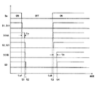
上記のように構成された変電装置の動作を図1乃至図3によって説明する。図3は変電装置の各部の動作を示すタイムチャートである。
三相開閉器100のスイッチS1,S2,S3がすべて投入されていて、三相交流電源3から三相変圧器7に電力が供給されており、各鉄心脚7a〜7cには、大きさは同一で位相が120°ずれた磁束φu,φv,φwが流れている状態において、時間tsfで指令スイッチSaを閉成から開放すると、コイルC1の励磁が解除され、スイッチS1が遮断すると共に、補助常開接点S11が開放する。
【0017】
この状態において、三相交流電源3から三相変圧器7のV相となる端子t2,t3に線間電圧Eが印加されているので、U相となる端子t1,t2、W相となる端子t1,t3の電圧がE/2になる。
したがって、三相変圧器5の各相の磁束の大きさは、V相を|φv|=φmとすれば、U,W相が|φu|=|φw|=φm/2となる。すなわち、中央の鉄心脚7bにおける磁束の大きさ|φv|は、端子t1〜t3の端子が三相交流電源3に接続されていた時の磁束の大きさφmと変わらないが、両端の鉄心脚7a,7cにおける磁束の大きさ|φu|,|φw|はφm/2になる。
【0018】
そして、補助常開接点S11が閉放した後、開放してから時間ta後にタイマA107の出力がオフ信号を発生してトランジスタTr1もオフとなり、コイルC2の励磁が解除されて時間t1でスイッチS2を遮断する。すなわち、遮断指令から第1の所定時間後にスイッチS2が遮断される。
スイッチS2の遮断と同時に補助常開接点S21が開放してタイマB109の出力がオフ信号を発生してトランジスタTr2もオフとなり、コイルC3の励磁が解除されて時間t2でスイッチS3を遮断する。すなわち、遮断指令から第2の所定時間後にスイッチS3が遮断される。
したがって、三相変圧器7の各鉄心脚7a〜7cには遮断前の磁束の大きさに比例した残留磁束が残り、該残留磁束は右端の鉄心脚7a,左端の鉄心脚7bが中央の鉄心脚7cの1/2となる。
【0019】
次に、時間tsNで、指令スイッチSaを開放から閉成すると、コイルC1が励磁され、スイッチS1が投入されると共に、常開補助接点S11が閉成され、タイマA107の出力がオン信号を発生してトランジスタTr1もオンとなり、コイルC2を励磁して時間t3で、スイッチS2を投入する。すなわち、投入指令から第3の所定時間後にスイッチS2が投入される。スイッチS1,S2の投入により、三相変圧器7の端子t1,t2に三相交流電源3の電圧を印加して励磁突入電流I0が生じる。
この端子t1,t2に単相電圧Eが印加された状態において、U相となる左端の鉄心脚7aには、磁束|φu|=φmが生じ、V相となる中央の鉄心脚7b,W相となる右端の鉄心脚7cには、単相電圧の半分E/2の電圧が印加されるので、磁束|φv|,|φw|=φm/2が発生する。
したがって、最大励磁突入電流I1max はU相において生じ、定常状態磁束密度Bmを1.7(T)、残留磁束密度Brを0.9Bm/2とすると前記(2)式より下式となる。
I1max=K(2×1.7+0.9×1.7/2−2)=2.165K
【0020】
次に、スイッチS2の投入と共に、補助常開接点S21が閉成してから時間tb後に、タイマB109の出力がオン信号を発生してトランジスタTr2もオンとなり、コイルC3を励磁して時間t4でスイッチS3を投入する。すなわち、投入指令から第4の所定時間後にスイッチS3を投入することにより、端子t2,t3が端子t1,t2よりも所定時間(請求項1における第3の所定の時間)遅れて三相交流電源3から電圧が印加される。
このスイッチS3の投入時には、大きな励磁突入電流は生じない。これは、すでにスイッチS1,S2の投入によって三相変圧器7の端子t1,t2に三相交流電源3から単相電圧Eが印加され、各鉄心脚7a〜7cに磁束が流れているので、残留磁束がなくなるからである。
【0021】
一方、従来の励磁突入電流I0maxは定常状態磁束密度Bmを1.7(T)、残留磁束密度Brを0.9Bmとすると前記(2)式より下式となる。
I0max=K(2×1.7+0.9×1.7−2)=2.93K
この実施形態の励磁突入電流I1maxと従来の励磁突入電流I0maxとの比nを求める。
n=I1max/I0max=2.165K/2.93K≒0.74
すなわち、従来よりも励磁突入電流が26%減少するものである。
【0022】
前記実施の形態では、三相変圧器7が励磁されている状態、すなわち、スイッチS1〜S3が投入された状態において、スイッチS1を遮断して所定時間経過後にスイッチS2を遮断した後、スイッチS3を遮断したが、スイッチS1を遮断して所定時間経過した後、同時にスイッチS2,S3を遮断しても良い。
さらに、スイッチS1を遮断して所定時間経過後にスイッチS3を遮断した後、スイッチS2を遮断しても良い。
また、同様に、三相変圧器7が無励磁の状態、すなわち、スイッチS1〜S3が遮断された状態において、V相(第2相)がU相(第1相)よりも所定時間(請求項1における第3の所定時間)遅れて三相交流電源3の電圧が印加されるようにスイッチS1〜S3を投入したが、V相(第2相)がW相(第3相)よりも所定時間(請求項1における第3の所定時間)遅れて三相交流電源3の電圧が印加されるようにスイッチS1〜S3を投入しても良い。
また、同様に、三相変圧器7が無励磁の状態において、スイッチS1を投入した後、投入指令から第3の所定時間後にスイッチS2を投入すると共に、投入指令から第4の所定時間後にスイッチS3を投入したが、スイッチS1を投入した後、投入指令から第3の所定時間後にスイッチS3を投入すると共に、投入指令から第4の所定時間後にスイッチS2を投入しても良い。
さらに、最初にスイッチS1,S2を同時に投入して所定時間後に、スイッチS3を投入しても良い。さらに、最初にスイッチS1,S3を同時に投入して所定時間後に、スイッチS2を投入しても良い。
また、前記実施の形態では、三相変圧器7はデルタ結線としたが、スター結線でも励磁突入電流は従来よりも減少する。
なお、スイッチS1〜S3は、半導体素子により構成しても良い。
【図面の簡単な説明】
【図1】 この発明の一実施の形態による変電装置の接続図である。
【図2】 図1に示す三相開閉器及び鉄心とコイルとから成る三相変圧器の接続図である。
【図3】 図1に示す変電装置の各部の動作を示すタイムチャートである。
【図4】 従来の変電装置の接続図である。
【符号の説明】
S1 第1の開閉部、S2 第2の開閉部、S3 第3の開閉部、t1
第1の端子、t2 第2の端子、t3 第3の端子、3 三相交流電源、7 三相変圧器、100 三相開閉器、105 制御部(遮断制御手段,投入制御手段)。[0001]
BACKGROUND OF THE INVENTION
The present invention relates to an improvement of a three-phase switch that turns on and off a transformer in a power source, and more particularly to a three-phase switch that reduces the excitation inrush current of the three-phase transformer.
[0002]
[Prior art]
A substation to which a conventional three-phase switch is applied will be described with reference to FIG. In FIG. 4, the
[0003]
When the switches S1, S2 and S3 of the three-phase switch 5 are simultaneously turned on to apply the voltage of the three-phase
[0004]
The maximum value I 0max of the magnetizing inrush current is applied when the instantaneous value of the power supply voltage is zero and the residual magnetic flux in the iron core of the three-
I 0max = K · (2B m + B r −B S ) (1)
Where, K: proportional constant, B m : steady state magnetic flux density (T)
B r : residual magnetic flux density (T), B S : saturation magnetic flux density (T)
Here, since the saturation magnetic flux density B S is generally about 2 Tesla, the equation (1) becomes the following equation.
I 0max = K · (2B m + B r −2) (2)
Since the magnetizing inrush current causes malfunction of the protective device, a countermeasure is taken to reduce the magnetizing inrush current. In order to reduce the magnetizing inrush current, the steady state magnetic flux density B m and the residual magnetic flux density B r from the above equation (2). There is a reduction means.
[0005]
[Problems to be solved by the invention]
However, if the steady-state magnetic flux density Bm is halved, for example, the cross-sectional area of the iron core of the three-
[0006]
Further, in order to reduce the residual magnetic flux density Br, a butt joint may be provided on the iron core of the three-
[0007]
The present invention has been made to solve the above-described problems, and a three-phase switch that reduces excitation inrush current by appropriately executing a timing at which a so-called standard transformer is turned on / off to a three-phase AC power source. The purpose is to provide.
[0008]
[Means for solving the problems, actions and effects of the invention]
A three-phase switch according to a first invention has first to third terminals, a first phase connected between the first and second terminals, and between the second and third terminals. To turn on and off the voltage to the first to third terminals of the three-phase transformer with the second phase connected, the third phase connected between the first and third terminals, respectively. A three-phase switch connected to a three-phase AC power source, the first and third switchgears being connected to the first and third switchgears; And then shuts off the second opening / closing part after a first predetermined time from the shut-off command and shuts off the second opening / closing part after a second predetermined time from the shut-off command. 3 and the second phase of the three-phase transformer is the first phase or the third phase. The first to third opening / closing sections are turned on based on the opening / closing section turn-on command so that the three-phase AC power supply is turned on to the first to third terminals after a third predetermined time delay. The first predetermined time and the second predetermined time are one period or more of the frequency of the three-phase AC power supply .
Here, the first predetermined time may be longer or shorter than the second predetermined time. According to such a three-phase switch, in the state where the three-phase transformer is excited, two of the three phases are shut off by shutting off the first switch before the second and third switches. After reducing the residual magnetic flux of the phase, the second switching unit and the third switching unit are shut off after a predetermined time to shut off the three-phase transformer from the three-phase AC power source. When exciting a three-phase transformer, the second phase having a large residual magnetic flux is inserted into the three-phase transformer in all phases of the three-phase transformer by turning on and off the switching unit after a third predetermined time from the first phase or the third phase. Apply voltage. Therefore, since the magnetizing inrush current is reduced by first applying power to one phase of the three-phase transformer having a reduced residual magnetic flux density, there is an effect that the magnetizing inrush current can be reduced while using a general transformer. .
[0009]
A three-phase switch according to a second invention is a three-phase switch having first to third switch parts connected to a three-phase transformer and connected to a three-phase AC power source. In a state where the first to third opening / closing parts are turned on, the first opening / closing part is shut off based on the opening / closing part shut-off command, and then the second opening / closing part after a first predetermined time from the shut-off command. And a shutoff control means for shutting off the third opening / closing portion after a second predetermined time from the shutoff command, and after the first opening / closing portion is turned on based on the closing command of the opening / closing portion, The second opening / closing portion is turned on after a third predetermined time from the occurrence of the occurrence, and the third opening / closing portion is turned on after a fourth predetermined time different from the third predetermined time from the occurrence of the making command. and a control unit, the said the first and the fourth predetermined time, the upper It is characterized in that at least one cycle of the frequency of the three-phase AC power source.
Here, the third predetermined time may be longer or shorter than the fourth predetermined time. According to such a three-phase switch, in the state where the three-phase transformer is excited, two of the three phases are shut off by shutting off the first switch before the second and third switches. After reducing the residual magnetic flux of the phase, the second switching unit and the third switching unit are shut off after a predetermined time to shut off the three-phase transformer from the three-phase AC power source. When energizing the three-phase transformer, after the first switching part is first turned on, the second switching part is turned on after a third predetermined time, for example, so that the three-phase AC power After applying the phase voltage, the third switching unit is turned on to apply a three-phase AC voltage to the three-phase transformer. Therefore, since the magnetizing inrush current is reduced by first applying power to one phase of the three-phase transformer having a reduced residual magnetic flux density, there is an effect that the magnetizing inrush current can be reduced while using a general transformer. .
[0010]
A three-phase switch according to a third aspect of the invention is a three-phase switch having first to third switch units connected to a three-phase transformer and connected to a three-phase AC power source. In a state where the first to third opening / closing parts are turned on, the first opening / closing part is shut off based on the opening / closing part shut-off command, and then the second opening / closing part after a first predetermined time from the shut-off command. And a shutoff control means for shutting off the third opening / closing part after a second predetermined time from the shutoff command, the first opening / closing part based on the opening / closing part input command, and the second or second And a closing control means for closing the third or second opening / closing portion that has not been turned on after a third predetermined time from the occurrence of the turning command . wherein the predetermined time is more than one period of the frequency of the three-phase AC power supply It is intended to.
According to such a three-phase switch, in the state where the three-phase transformer is excited, two of the three phases are shut off by shutting off the first switch before the second and third switches. After reducing the residual magnetic flux of the phase, the second switching unit and the third switching unit are shut off after a predetermined time to shut off the three-phase transformer from the three-phase AC power source. When exciting the three-phase transformer, the first voltage is first applied to the one phase with a small residual magnetic flux by the first switching unit and the second or third switching unit, and then the third phase is not turned on. Alternatively, a voltage is applied to all phases of the three-phase transformer by turning on the second switch. Therefore, since the magnetizing inrush current is reduced by first applying power to one phase of the three-phase transformer having a reduced residual magnetic flux density, there is an effect that the magnetizing inrush current can be reduced while using a general transformer. .
[0011]
A three-phase switch according to a fourth invention is characterized in that the first and second predetermined times are the same in the first or second invention.
According to such a three-phase switch, since the second and third switchgears were shut off after the same predetermined time after the first switchgear was shut off, the three-phase transformer was quickly shut off from the three-phase AC power source. There is an effect that can be done.
[0012]
In any one of the three-phase switches according to the first to fourth inventions, the first to fourth predetermined times are one period or more of the frequency of the three-phase AC power supply. According to such a three-phase switch, since the first to fourth predetermined times are one cycle or more of the frequency of the three-phase AC power supply, the next switching is performed after the magnetic flux of each phase of the three-phase transformer is established. Since the portion can be turned on or off, there is an effect that the magnetizing inrush current can be reliably reduced.
[0013]
DETAILED DESCRIPTION OF THE INVENTION
An embodiment of the present invention will be described with reference to FIGS. FIG. 1 is a connection diagram of a substation device according to an embodiment, and FIG. 2 is a connection diagram of a three-phase transformer shown in FIG. 1 and a three-phase transformer composed of an iron core and a coil. An embodiment applied to a substation will be described.
1 and 2, the
Further, the three-
[0014]
The three-
One end of the auxiliary normally open contact S11 that opens and closes in synchronization with the switch S1 is connected to the signal power source, and the other end of the auxiliary normally open contact S11 is connected to the input of the timer A107. through 1 is connected to the base of the transistor Tr 1, the collector of the transistor Tr 1 is connected to the control power supply through the coil C2.
One end of the auxiliary normally open contact S21 that opens and closes in synchronization with the switch S2 is connected to the signal power source, and the other end of the auxiliary normally open contact S21 is connected to the input of the timer B109. is connected to the base of the transistor Tr 2 via the 2, the collector of the transistor Tr 2 is connected to the control power supply through the coil C3. The emitters of the transistors Tr 1 and Tr 2 are grounded.
[0015]
The timer A107 generates an ON signal immediately after the auxiliary normally open contact S11 is closed, and continuously generates an ON signal while the auxiliary normally open contact S11 is closed. An off signal is generated a time ta after S11 is released.
The timer B109 generates an ON signal after a time tb after the auxiliary normally open contact S21 is closed, and once the ON signal is generated and while the auxiliary normally open contact S21 is closed, Is generated, and an off signal is generated immediately after the auxiliary normally open contact S21 is opened.
Here, the times ta and tb are preferably set to one cycle or more of the power supply frequency of the three-phase
[0016]
The operation of the substation apparatus configured as described above will be described with reference to FIGS. FIG. 3 is a time chart showing the operation of each part of the transformer.
The switches S1, S2, S3 of the three-
[0017]
In this state, since the line voltage E is applied from the three-phase
Therefore, the magnitude of the magnetic flux of each phase of the three-phase transformer 5 is such that if the V phase is | φv | = φm, the U and W phases are | φu | = | φw | = φm / 2. That is, the magnitude | φv | of the magnetic flux in the
[0018]
Then, the auxiliary after the normally open contact S11 is the閉放, the output of the timer A107 from the open after time ta the transistor Tr 1 occurring off signal is also turned off, by the excitation is canceled time t 1 of the coil C2 Switch S2 is shut off. That is, the switch S2 is shut off after a first predetermined time from the shutoff command.
Blocking at the same time the auxiliary output of the normally open contact S21 is open timer B109 of switch S2 transistor Tr 2 to generate an OFF signal is also turned off, to cut off the switch S3 exciting coil C3 is released at time t 2 . That is, the switch S3 is turned off after the second predetermined time from the turn-off command.
Therefore, a residual magnetic flux proportional to the magnitude of the magnetic flux before interruption remains in each of the
[0019]
Next, when the command switch Sa is closed from the open state at time tsN , the coil C1 is excited, the switch S1 is turned on, the normally open auxiliary contact S11 is closed, and the output of the timer A107 is turned on. transistor Tr 1 is also turned on occurs, at time t 3 by exciting the coils C2, turning on the switch S2. That is, the switch S2 is turned on after a third predetermined time from the turning-on command. With the introduction of the switches S1, S2, three-
In a state where the single-phase voltage E is applied to the terminals t1 and t2, a magnetic flux | φu | = φm is generated in the leftmost
Therefore, the maximum excitation inrush current I 1max occurs in the U phase, and the following equation is obtained from the above equation (2) when the steady state magnetic flux density B m is 1.7 (T) and the residual magnetic flux density B r is 0.9 B m / 2. It becomes.
I 1max = K (2 × 1.7 + 0.9 × 1.7 / 2-2) = 2.165K
[0020]
Next, the introduction of switch S2, auxiliary to the normally open contact S21 is after time tb from the closing, the output of the timer B109 the transistor Tr 2 to generate an ON signal become on, time by exciting the coil C3 t In step 4 , the switch S3 is turned on. That is, by turning on the switch S3 after a fourth predetermined time from the input command, the terminals t2 and t3 are delayed by a predetermined time (third predetermined time in claim 1) from the terminals t1 and t2, and the three-phase AC power supply A voltage is applied from 3.
When the switch S3 is turned on, a large magnetizing inrush current does not occur. This is because the single-phase voltage E is already applied from the three-phase
[0021]
On the other hand, the conventional magnetizing inrush current I 0max is expressed by the following equation from the above equation (2) when the steady state magnetic flux density B m is 1.7 (T) and the residual magnetic flux density B r is 0.9 B m .
I 0max = K (2 × 1.7 + 0.9 × 1.7-2) = 2.93K
A ratio n between the magnetizing inrush current I 1max of this embodiment and the conventional magnetizing inrush current I 0max is obtained.
n = I 1max / I 0max = 2.165K / 2.93K≈0.74
That is, the magnetizing inrush current is reduced by 26% compared to the conventional case.
[0022]
In the above embodiment, in a state where the three-
Furthermore, the switch S2 may be shut off after the switch S1 is shut off and the switch S3 is shut off after a predetermined time has elapsed.
Similarly, when the three-
Similarly, after the switch S1 is turned on when the three-
Further, the switches S1 and S2 may be turned on simultaneously, and the switch S3 may be turned on after a predetermined time. Further, the switches S1 and S3 may be simultaneously turned on first, and the switch S2 may be turned on after a predetermined time.
Moreover, in the said embodiment, although the three-
Note that the switches S1 to S3 may be composed of semiconductor elements.
[Brief description of the drawings]
FIG. 1 is a connection diagram of a transformer device according to an embodiment of the present invention.
2 is a connection diagram of the three-phase switch shown in FIG. 1 and a three-phase transformer composed of an iron core and a coil. FIG.
FIG. 3 is a time chart showing the operation of each part of the substation apparatus shown in FIG. 1;
FIG. 4 is a connection diagram of a conventional transformer.
[Explanation of symbols]
S1 first opening / closing part, S2 second opening / closing part, S3 third opening / closing part, t1
1st terminal, t2 2nd terminal, t3 3rd terminal, 3 three-phase alternating current power supply, 7 three-phase transformer, 100 three-phase switch, 105 control part (cut-off control means, closing control means).
Claims (4)
Priority Applications (1)
| Application Number | Priority Date | Filing Date | Title |
|---|---|---|---|
| JP2001056810A JP4765178B2 (en) | 2001-03-01 | 2001-03-01 | Three-phase switch |
Applications Claiming Priority (1)
| Application Number | Priority Date | Filing Date | Title |
|---|---|---|---|
| JP2001056810A JP4765178B2 (en) | 2001-03-01 | 2001-03-01 | Three-phase switch |
Publications (2)
| Publication Number | Publication Date |
|---|---|
| JP2002260476A JP2002260476A (en) | 2002-09-13 |
| JP4765178B2 true JP4765178B2 (en) | 2011-09-07 |
Family
ID=18916777
Family Applications (1)
| Application Number | Title | Priority Date | Filing Date |
|---|---|---|---|
| JP2001056810A Expired - Fee Related JP4765178B2 (en) | 2001-03-01 | 2001-03-01 | Three-phase switch |
Country Status (1)
| Country | Link |
|---|---|
| JP (1) | JP4765178B2 (en) |
Families Citing this family (6)
| Publication number | Priority date | Publication date | Assignee | Title |
|---|---|---|---|---|
| JP4721959B2 (en) * | 2006-06-12 | 2011-07-13 | 三菱電機株式会社 | Power switching control device |
| JP4999154B2 (en) * | 2006-11-24 | 2012-08-15 | 学校法人日本大学 | Reduced voltage starting device |
| JP4562747B2 (en) * | 2007-03-29 | 2010-10-13 | 旭化成ケミカルズ株式会社 | Transformer excitation inrush current suppression control method and apparatus |
| JP5208593B2 (en) * | 2008-06-20 | 2013-06-12 | 株式会社東芝 | Inrush current suppressing device for transformer and control method thereof |
| TWI542114B (en) * | 2015-06-17 | 2016-07-11 | 台達電子工業股份有限公司 | Photovoltaic inverter grid-connected system and method for implementing three-phase ac grid-connected transition |
| CN106329561B (en) * | 2015-06-17 | 2018-12-11 | 台达电子工业股份有限公司 | Solar inverter grid-connected system and three-phase grid method |
Family Cites Families (4)
| Publication number | Priority date | Publication date | Assignee | Title |
|---|---|---|---|---|
| JP2602935B2 (en) * | 1988-12-14 | 1997-04-23 | 株式会社東芝 | Gas circuit breaker for reactor opening and closing |
| JPH0471130A (en) * | 1990-07-10 | 1992-03-05 | Toshiba Corp | Three-phase vacuum circuit breaker |
| JPH11345546A (en) * | 1998-06-01 | 1999-12-14 | Kyushu Electric Power Co Inc | Method and device suppressing transformer exciting rush current |
| CN1173377C (en) * | 1998-07-16 | 2004-10-27 | 三菱电机株式会社 | Synchronous switchgear |
-
2001
- 2001-03-01 JP JP2001056810A patent/JP4765178B2/en not_active Expired - Fee Related
Also Published As
| Publication number | Publication date |
|---|---|
| JP2002260476A (en) | 2002-09-13 |
Similar Documents
| Publication | Publication Date | Title |
|---|---|---|
| JP2892717B2 (en) | Power switching controller | |
| US7787228B2 (en) | Switchgear control apparatus | |
| CA2670907A1 (en) | Magnetizing inrush current suppression device and method for transformer | |
| US10615592B2 (en) | Method for reducing the inrush current of an inductive load | |
| WO2011125210A1 (en) | Inrush-current alleviating device and method of alleviating inrush current | |
| JP4765178B2 (en) | Three-phase switch | |
| JP2011120396A (en) | Synchronous input system of transformer | |
| Zhou et al. | Asynchronous modular contactor for intelligent motor control applications | |
| JP2013037767A (en) | Magnetization rush current suppression device | |
| Kotak et al. | Prefluxing technique to mitigate inrush current of three-phase power transformer | |
| JP2006223083A (en) | Device to control magnetic flux of transformer in each iron core using direct current | |
| JP2004088834A (en) | Switch for scott connecting transformer | |
| JP2008043017A (en) | Kondorfer starting device for electric motor | |
| JP4388191B2 (en) | Power switching device | |
| Petrović et al. | Remanent flux measurement and optimal energization instant dertermination of power transformer | |
| JPH077978A (en) | Korndorfer method for starting motor | |
| CN110535110B (en) | Phase selection switching-on and switching-off control method and device for extra-high voltage alternating current transformer | |
| JP4706999B2 (en) | Excitation current suppression device | |
| JP2001231167A (en) | Method and apparatus for opening and closing capacitor equipment for three-phase alternating-current power | |
| JPH11225432A (en) | Transformer rush current reduction method | |
| JPS6055604A (en) | Control system of transformer | |
| JP3000922U (en) | A device that can suppress the generation of inrush current and turn it on and off from one cycle. | |
| KR200306494Y1 (en) | Three-phase power reduced Device using Mutual compensation induction | |
| Chavan et al. | Magnetic Inrush Current of Transformer Reduce By Point Wave Switching Method with MATLAB Simulation Results | |
| CN114123792A (en) | Control method for eliminating direct current offset of transformer in double-active-bridge converter |
Legal Events
| Date | Code | Title | Description |
|---|---|---|---|
| RD01 | Notification of change of attorney |
Free format text: JAPANESE INTERMEDIATE CODE: A7421 Effective date: 20040630 |
|
| A621 | Written request for application examination |
Free format text: JAPANESE INTERMEDIATE CODE: A621 Effective date: 20080125 |
|
| A977 | Report on retrieval |
Free format text: JAPANESE INTERMEDIATE CODE: A971007 Effective date: 20100802 |
|
| A131 | Notification of reasons for refusal |
Free format text: JAPANESE INTERMEDIATE CODE: A131 Effective date: 20100907 |
|
| A521 | Written amendment |
Free format text: JAPANESE INTERMEDIATE CODE: A523 Effective date: 20101101 |
|
| A01 | Written decision to grant a patent or to grant a registration (utility model) |
Free format text: JAPANESE INTERMEDIATE CODE: A01 Effective date: 20110517 |
|
| A61 | First payment of annual fees (during grant procedure) |
Free format text: JAPANESE INTERMEDIATE CODE: A61 Effective date: 20110530 |
|
| FPAY | Renewal fee payment (event date is renewal date of database) |
Free format text: PAYMENT UNTIL: 20140624 Year of fee payment: 3 |
|
| LAPS | Cancellation because of no payment of annual fees |