JP4762513B2 - Industrial two-layer fabric - Google Patents
Industrial two-layer fabric Download PDFInfo
- Publication number
- JP4762513B2 JP4762513B2 JP2004242258A JP2004242258A JP4762513B2 JP 4762513 B2 JP4762513 B2 JP 4762513B2 JP 2004242258 A JP2004242258 A JP 2004242258A JP 2004242258 A JP2004242258 A JP 2004242258A JP 4762513 B2 JP4762513 B2 JP 4762513B2
- Authority
- JP
- Japan
- Prior art keywords
- surface side
- warp
- layer
- weft
- wefts
- Prior art date
- Legal status (The legal status is an assumption and is not a legal conclusion. Google has not performed a legal analysis and makes no representation as to the accuracy of the status listed.)
- Active
Links
Images


Classifications
-
- D—TEXTILES; PAPER
- D21—PAPER-MAKING; PRODUCTION OF CELLULOSE
- D21F—PAPER-MAKING MACHINES; METHODS OF PRODUCING PAPER THEREON
- D21F1/00—Wet end of machines for making continuous webs of paper
- D21F1/0027—Screen-cloths
- D21F1/0036—Multi-layer screen-cloths
-
- Y—GENERAL TAGGING OF NEW TECHNOLOGICAL DEVELOPMENTS; GENERAL TAGGING OF CROSS-SECTIONAL TECHNOLOGIES SPANNING OVER SEVERAL SECTIONS OF THE IPC; TECHNICAL SUBJECTS COVERED BY FORMER USPC CROSS-REFERENCE ART COLLECTIONS [XRACs] AND DIGESTS
- Y10—TECHNICAL SUBJECTS COVERED BY FORMER USPC
- Y10S—TECHNICAL SUBJECTS COVERED BY FORMER USPC CROSS-REFERENCE ART COLLECTIONS [XRACs] AND DIGESTS
- Y10S162/00—Paper making and fiber liberation
- Y10S162/90—Papermaking press felts
-
- Y—GENERAL TAGGING OF NEW TECHNOLOGICAL DEVELOPMENTS; GENERAL TAGGING OF CROSS-SECTIONAL TECHNOLOGIES SPANNING OVER SEVERAL SECTIONS OF THE IPC; TECHNICAL SUBJECTS COVERED BY FORMER USPC CROSS-REFERENCE ART COLLECTIONS [XRACs] AND DIGESTS
- Y10—TECHNICAL SUBJECTS COVERED BY FORMER USPC
- Y10S—TECHNICAL SUBJECTS COVERED BY FORMER USPC CROSS-REFERENCE ART COLLECTIONS [XRACs] AND DIGESTS
- Y10S162/00—Paper making and fiber liberation
- Y10S162/902—Woven fabric for papermaking drier section
-
- Y—GENERAL TAGGING OF NEW TECHNOLOGICAL DEVELOPMENTS; GENERAL TAGGING OF CROSS-SECTIONAL TECHNOLOGIES SPANNING OVER SEVERAL SECTIONS OF THE IPC; TECHNICAL SUBJECTS COVERED BY FORMER USPC CROSS-REFERENCE ART COLLECTIONS [XRACs] AND DIGESTS
- Y10—TECHNICAL SUBJECTS COVERED BY FORMER USPC
- Y10S—TECHNICAL SUBJECTS COVERED BY FORMER USPC CROSS-REFERENCE ART COLLECTIONS [XRACs] AND DIGESTS
- Y10S162/00—Paper making and fiber liberation
- Y10S162/903—Paper forming member, e.g. fourdrinier, sheet forming member
-
- Y—GENERAL TAGGING OF NEW TECHNOLOGICAL DEVELOPMENTS; GENERAL TAGGING OF CROSS-SECTIONAL TECHNOLOGIES SPANNING OVER SEVERAL SECTIONS OF THE IPC; TECHNICAL SUBJECTS COVERED BY FORMER USPC CROSS-REFERENCE ART COLLECTIONS [XRACs] AND DIGESTS
- Y10—TECHNICAL SUBJECTS COVERED BY FORMER USPC
- Y10T—TECHNICAL SUBJECTS COVERED BY FORMER US CLASSIFICATION
- Y10T442/00—Fabric [woven, knitted, or nonwoven textile or cloth, etc.]
- Y10T442/30—Woven fabric [i.e., woven strand or strip material]
- Y10T442/3472—Woven fabric including an additional woven fabric layer
Description
本発明は搬送、脱水等に使用され、特に製紙用に好適に用いられる二層織物に関する。 The present invention relates to a two-layer fabric used for conveyance, dehydration and the like, and particularly suitable for papermaking.
従来から工業用織物としては経糸、緯糸で製織した織物が広く使用されており、例えば抄紙用ワイヤーや搬送用ベルト、ろ布等その他にも多くの分野で使用されており、用途や使用環境に適した織物特性が要求されている。特に織物の網目を利用して原料の脱水等を行う製紙工程で使用される抄紙用ワイヤーでの要求は厳しく、紙に織物のワイヤーマークを転写することのない表面性に優れた織物、また過酷な環境下においても好適に使用できる程度の剛性を持ち合わせたもの、そして良好な紙を製造するために必要な条件を長期間持続することのできる織物等が要求されている。その他にも繊維支持性、製紙の歩留まりの向上、良好なろ水性、耐摩耗性、寸法安定性、走行安定性等が要求されている。さらに近年では抄紙マシンが高速化しているため、それに伴い抄紙用ワイヤーへの要求も一段と厳しいものとなっている。
このように工業用織物の中でも最も要求が厳しい抄紙用織物について説明すればほとんどの工業用織物の要求とその解決について理解できるので、以下抄紙用織物を代表して本発明を説明する。
製紙機械において、抄紙スピードが高速になると必然的に脱水スピードが高速になり、脱水力を強力にする必要がある。脱水性の良い織物としては、上層面側から下層面側にまで貫通する脱水孔が形成される二層織物等がある。特に製紙用織物に要求される表面性、繊維支持性、脱水性を満たすことを目的とした織物として、上層面側緯糸、下層面側緯糸と織り合わされて上層面側表面組織と下層面側表面組織を形成する経地糸接結糸を用いた二層織物等がある。特開2004−36052号公報には経地糸接結糸を用いた二層織物が示されている。該従来発明は経糸が上層面側層と下層面側層を織り合わせる接結糸として機能するものであり、同時に組になった経地糸接結糸が上層面側表面組織と下層面側表面組織の一部を補完し合い、各々の表面組織を形成するため、表面性、接結強度に優れた織物となる。しかし、特開2004−36052号の実施例1〜3にある織物の下層面側組織は下層面側経糸が2本平行に同組織で配置された畝織り組織であり、下層面側緯糸が経糸2本分の短いクリンプであるため耐摩耗性には劣っていた。
また該二層織物は上層面側層から下層面側層まで完全に貫通する脱水孔が全面に配置されているため脱水性は良好ではあるが、強力なバキューム等によりワイヤー上のシート原料が織物に刺さり込んだり、繊維や填料等の抜けが発生し、脱水マークの発生が顕著になることもある。
このように表面性、繊維支持性および耐摩耗性等の全てを満足させる工業用織物は未だ開発されていない。
As described above, the papermaking fabrics, which are the most demanding of industrial fabrics, can be understood to understand the requirements and solutions of most industrial fabrics. Therefore, the present invention will be described below on behalf of papermaking fabrics.
In a papermaking machine, if the papermaking speed is increased, the dewatering speed is inevitably increased, and the dewatering power must be strengthened. Examples of the fabric having good dewaterability include a two-layer fabric in which a dewatering hole penetrating from the upper layer surface side to the lower layer surface side is formed. In particular, weaving the upper layer side weft and the lower layer side weft as a fabric aimed at satisfying the surface properties, fiber support, and dewatering properties required for papermaking fabrics. There are two-layer fabrics using warp binding yarns that form a structure. JP-A-2004-36052 discloses a two-layer fabric using warp binding yarns. In the conventional invention, the warp functions as a binding yarn that interweaves the upper layer side layer and the lower layer side layer, and at the same time, the warp binding yarn that is paired is the upper layer side surface structure and the lower layer side surface. Since a part of the structure is complemented and each surface structure is formed, the woven fabric has excellent surface properties and bonding strength. However, the lower surface side structure of the woven fabric according to Examples 1 to 3 of JP-A-2004-36052 is a woven weave structure in which two lower surface side warps are arranged in parallel in the same structure, and the lower surface side weft is a warp. Since it was a short crimp for two, it was inferior in abrasion resistance.
In addition, the two-layer fabric has good dewaterability because the dewatering holes that completely penetrate from the upper layer side layer to the lower layer side layer are arranged on the entire surface, but the sheet material on the wire is woven by strong vacuum etc. In some cases, the fiber may be pierced or fibers or fillers may fall out, resulting in a marked dehydration mark.
As described above, an industrial fabric satisfying all of the surface property, the fiber support property, the wear resistance and the like has not been developed yet.
本発明は、上記の問題を鑑みて、急激な脱水およびそれによる脱水マークの発生を抑制し、表面性、繊維支持性、耐摩耗性に優れた工業用織物を提供しようとするものである。 In view of the above problems, the present invention is intended to provide an industrial fabric excellent in surface properties, fiber support properties, and abrasion resistance by suppressing rapid dehydration and the resulting dehydration mark.
本発明は、
「1.8本の上層面側経糸と8本の下層面側経糸を上下に配置することによってできる8組の経糸と、複数本の上層面側緯糸と下層面側緯糸から構成され、前記経糸の組のうち、少なくとも1組以上が2本組になった経地糸接結糸、または経地糸接結糸と上層面側経糸の組、または経地糸接結糸と下層面側経糸の組のいずれかによって構成されてなる上層面側層と下層面側層を経方向の糸で接結してなる工業用二層織物において、下層面側層は、経糸が連続する4本の下層面側緯糸の上を通り、次に1本の下層面側緯糸の下を通り、次に2本の下層面側緯糸の上を通った後、1本の下層面側緯糸の下を通る組織を、下層面側緯糸3本分シフトさせて順次配置する繰返しにより構成され、隣り合う2本の下層面側経糸が1本の下層面側緯糸を下層面側から同時に織り込むことで下層面側緯糸が下層面側表面に下層面側経糸6本分の緯糸ロングクリンプを形成すると同時に下層面側経糸が隣り合う左右の下層面側経糸と交互に隣接しながらジグザグ配置されていることを特徴とする工業用二層織物。
2.8組の上下に配置された上層面側経糸と下層面側経糸のうち、1組以上の上層面側経糸と下層面側経糸の両方が、上層面側緯糸および下層面側緯糸と織り合わされて上層面側表面組織の一部と下層面側表面組織の一部を形成する経地糸接結糸であり、上層面側表面は組になった経地糸接結糸がそれぞれ別の上層面側緯糸と織り合わされ、それらが協働して上層面側完全組織を構成する1本の経糸として機能し、且つ下層面側表面では組になった経地糸接結糸が下層面側経糸と同じ下層面側表面組織を形成する、請求項1に記載された工業用二層織物。
3.8組の上下に配置された上層面側経糸と下層面側経糸のうち、1組以上の上層面側経糸が、上層面側緯糸および下層面側緯糸と織り合わされて上層面側表面組織の一部と下層面側表面組織の一部を形成する経地糸接結糸であり、該経地糸接結糸と下層面側経糸の組では、上層面側表面は経地糸接結糸が上層面側緯糸と織り合わされて上層面側完全組織を構成する1本の経糸として機能し、且つ下層面側表面では組になった経地糸接結糸と下層面側経糸が協働して他の下層面側経糸と同じ下層面側表面組織を形成する、請求項1に記載された工業用二層織物。
4.8組の上下に配置された上層面側経糸と下層面側経糸のうち、1組以上の下層面側経糸が、上層面側緯糸および下層面側緯糸と織り合わされて上層面側表面組織の一部と下層面側表面組織の一部を形成する経地糸接結糸であり、該経地糸接結糸と上層面側経糸の組では、上層面側表面は経地糸接結糸と上層面側緯糸がそれぞれ別の上層面側緯糸と織り合わされ、それらが協働して上層面側完全組織を構成する1本の経糸として機能し、且つ下層面側表面では経地糸接結糸が下層面側経糸と同じ下層面側表面組織を形成する、請求項1に記載された工業用二層織物。
5.前記組になった経地糸接結糸が、一方の経地糸接結糸が少なくとも1本の上層面側緯糸と織り合わされ上層面側表面組織を形成しているところの下側で、もう一方の経地糸接結糸が1本の下層面側緯糸と織り合わされ、且つ、一方の経地糸接結糸が1本の下層面側緯糸と織り合わされているところの上側で、もう一方の経地糸接結糸が少なくとも1本の上層面側緯糸と織り合わされ上層面側表面組織を形成し、1組の経地糸接結糸が上層面側表面組織と下層面側表面組織を互いに補完し合って各々の表面組織を形成する、請求項2に記載された工業用二層織物。
6.上層面側完全組織が1種類の経糸完全組織からなる、請求項1ないし5のいずれか1項に記載された工業用二層織物。
7.上層面側完全組織が2種類以上の経糸完全組織からなる、請求項1ないし5のいずれか1項に記載された工業用二層織物。
8.上層面側表面組織が、2シャフトの平織、4シャフトの綾織り、4シャフトの崩し綾織り、8シャフトの綾織り、8シャフトの崩し綾織りのいずれかである、請求項1ないし7のいずれか1項に記載された工業用二層織物。
9.上層面側緯糸間に1本または2本以上の補助緯糸を配置する、請求項1ないし8のいずれか1項に記載された工業用二層織物。
10.上層面側緯糸本数が下層面側緯糸本数の1から2倍の本数である、請求項1ないし9のいずれか1項に記載された工業用二層織物。
11.上層面側経糸の線径と下層面側経糸の線径が等しい、請求項1ないし10のいずれか1項に記載された工業用二層織物。」に関する。
The present invention
“1.8 upper layer side warp and eight lower layer side warp are arranged in an up-down direction and are composed of eight sets of warps, a plurality of upper layer side wefts and lower layer side wefts, Of these pairs, at least one pair of warp binding yarns, or a combination of warp binding yarns and upper surface side warps, or warp binding yarns and lower surface side warps In the industrial two-layer woven fabric formed by joining the upper layer side layer and the lower layer side layer constituted by any of the above-mentioned sets with warp direction yarns, the lower layer side layer is composed of four continuous warp yarns. Passes over the lower surface side weft, then passes under one lower surface side weft, then passes over the two lower surface side wefts, and then passes under one lower surface side weft The structure is formed by repeating the arrangement by shifting the lower surface side wefts by three, and the adjacent two lower surface side warps lower one lower surface side weft. By weaving simultaneously from the surface side, the lower surface side wefts form a weft long crimp for the lower surface side warp on the lower surface side surface, and at the same time the lower surface side warp is alternately adjacent to the adjacent left and right lower surface side warps An industrial two-layer fabric characterized in that it is arranged in a zigzag.
2.8 Of the upper and lower surface side warps and lower surface side warps arranged above and below, both the upper surface side warp and the lower surface warp are woven with the upper surface side weft and the lower surface side weft. The warp binding yarns are combined to form part of the upper surface side surface structure and part of the lower surface side surface structure, and the upper surface side surface has different warp binding yarns in pairs. Interwoven with upper layer side wefts, they work together to function as a single warp constituting the upper layer side complete structure, and the warp binding yarns that form a pair on the lower surface side are the lower surface side The industrial two-layer woven fabric according to
3.8 Of the upper layer side warp and the lower layer side warp arranged above and below, one or more upper layer side warps are interwoven with the upper layer side weft and the lower layer side weft to form the upper layer surface texture A warp binding yarn that forms part of the surface texture and a part of the lower surface side surface structure. In the set of warp binding yarn and lower surface warp, the upper surface side surface is the warp binding surface. The warp yarns interweave with the upper surface side wefts to function as one warp constituting the upper surface side complete structure, and the warp binding yarns and lower surface side warps that are paired together on the lower surface surface cooperate The industrial two-layer woven fabric according to
4.8 Of the upper and lower surface side warps and the lower surface warp arranged in the upper and lower groups, one or more lower surface side warps are interwoven with the upper surface side wefts and the lower surface side wefts to form an upper surface side surface structure. A warp binding yarn that forms part of the surface texture and a part of the lower surface side surface structure, and in the set of warp binding yarn and upper surface side warp, the upper surface side surface is the warp binding surface Yarn and upper surface side weft are interwoven with different upper surface side wefts, and they work together to function as one warp that constitutes the upper layer side complete structure. The industrial two-layer fabric according to
5. The pair of warp binding yarns in the pair is already below the one where one warp binding yarn is interwoven with at least one upper surface side weft to form an upper surface side surface texture. One warp binding yarn is woven with one lower surface side weft and one warp binding yarn is woven with one lower surface side weft, the other The warp binding yarns are interwoven with at least one upper surface side weft to form an upper surface side surface structure, and one set of warp binding yarns forms an upper surface side surface structure and a lower surface side surface structure. The industrial two-layer fabric according to
6). The industrial two-layer woven fabric according to any one of
7). The industrial two-layer fabric according to any one of
8). The upper surface side surface structure is any one of 2-shaft plain weave, 4-shaft twill, 4-shaft twill, 8-shaft twill, and 8-shaft twill. An industrial two-layer fabric described in
9. The industrial two-layer fabric according to any one of
10. The industrial two-layer fabric according to any one of
11. The industrial two-layer fabric according to any one of
8本の上層面側経糸と8本の下層面側経糸を上下に配置することによってできる8組の経糸と、複数本の上層面側緯糸と下層面側緯糸から構成され、上層面側層と下層面側層を経方向の糸で接結してなる工業用二層織物の下層面側層を、経糸が連続する4本の下層面側緯糸の上を通り、次に1本の下層面側緯糸の下を通り、次に2本の下層面側緯糸の上を通った後、1本の下層面側緯糸の下を通る組織を下層面側緯糸3本分シフトさせて順次配置した完全組織とし、隣り合う2本の下層面側経糸が1本の下層面側緯糸を下層面側から同時に織り込むことで下層面側緯糸が下層面側表面に下層面側経糸6本分の緯糸ロングクリンプを形成すると同時に下層面側経糸が隣り合う左右の下層面側経糸と交互に隣接しながらジグザグ配置する織物としたことにより、織物の剛性、斜め剛性、耐摩耗性を向上し、上層面側層を構成する経方向の糸と下層面側層を構成する経方向の糸の重なる部分と重ならない部分が混在し、ろ水性を不均一にすることで脱水が段階的に起きるため、脱水マークの発生、ワイヤー上のシート原料の刺さり込み、繊維や填料等の抜けを抑制することができる。 It is composed of 8 sets of warps which can be arranged by vertically arranging 8 upper surface side warps and 8 lower surface side warps, and a plurality of upper surface side wefts and lower surface side wefts. The lower layer side layer of the industrial two-layer fabric formed by joining the lower layer side layers with warp yarns passes over the four lower layer side wefts where warps continue, and then one lower layer surface Completely placed after passing under the side weft and then over the two lower surface side wefts, shifting the structure passing under one lower surface side weft by three lower surface side wefts Adjacent two lower surface side warps are weaved together and one lower surface side weft is weaved simultaneously from the lower surface side, so that the lower surface side weft is on the lower surface side surface and weft long crimp for the lower surface side warp At the same time, the lower layer side warp is zigzag arranged alternately adjacent to the left and right lower layer side warps. This improves the rigidity, diagonal rigidity, and abrasion resistance of the fabric, and the warp direction yarns that make up the upper layer side layer and the warp direction yarns that make up the lower layer side layer overlap with the overlapping part. Since dewatering occurs stepwise by making the drainage non-uniform, it is possible to suppress the generation of dehydration marks, the penetration of sheet material on the wire, and the loss of fibers and fillers.
本発明は、8本の上層面側経糸と8本の下層面側経糸を上下に配置することによってできる8組の経糸と、複数本の上層面側緯糸と下層面側緯糸から構成され、上層面側層と下層面側層を経方向の糸で接結してなる工業用二層織物であり、下層面側層では、経糸が連続する4本の下層面側緯糸の上側を通り、次いで1本の下層面側緯糸の下側を通り、次いで連続する2本の下層面側緯糸の上側を通り、次いで1本の下層面側緯糸の下側を通る組織であり、次の下層面側経糸を下層面側緯糸3本分ずらして順次配置する繰り返しにより、2本の下層面側経糸が隣り合い、2本の下層面側経糸が1本の下層面側緯糸を下層面側から同時に織り込むことで下層面側表面に下層面側経糸6本分の緯糸ロングクリンプを形成すると同時に、下層面側経糸が左右の下層面側経糸と交互に隣接することで下層面側経糸はジグザグ配置されていることを特徴とする。
隣接する2本の下層面側経糸が下層面側緯糸を強固に織り込むため剛性に優れ、また下層面側表面に下層面側経糸6本分の緯糸ロングクリンプが形成されるため耐摩耗性を向上させることができる。そして、下層面側緯糸は経糸との織り込み回数が少ないため、下層面側緯糸の打込本数を増やしたり、下層面側緯糸の線径を太くしたりすることができる。下層面側経糸を隣り合う左右の下層面側経糸と交互に隣接しながらジグザグに配置する組織としたことで、上層面側層を構成する経方向の糸と下層面側層を構成する経方向の糸が重なる部分と重ならない部分が混在する構造とした。これによりランダムな大きさや形状の網目ができるため、段階的に脱水が進行し、脱水マークの発生、ワイヤー上のシート原料の刺さり込み、繊維や填料等の抜けを抑制することができる。さらに、下層面側経糸がジグザグに配置する組織としたことで織物の斜め方向の剛性も向上できる。
本発明の工業用二層織物は8本の上層面側経糸と8本の下層面側経糸を上下に配置することによってできる8組の経糸と、複数本の上層面側緯糸と下層面側緯糸から構成されており、上層面側層と下層面側層を織り合わせる接結糸には、上層面側緯糸および下層面側緯糸と織り合わされて上層面側表面組織の一部と下層面側表面組織の一部を形成する経地糸接結糸を用いた。
The present invention is composed of eight sets of warps that can be arranged by vertically arranging eight upper surface side warps and eight lower surface side warps, a plurality of upper surface side wefts and lower surface side wefts, It is an industrial two-layer woven fabric in which the layer side layer and the lower layer side layer are joined by warp direction yarns. In the lower layer side layer, the upper side of four lower surface side wefts where warp yarns are continuous, A structure that passes under one lower surface side weft, then passes over two consecutive lower surface side wefts, and then passes under one lower surface side weft. Two lower surface side warps are adjacent to each other, and two lower surface side warps simultaneously weave one lower surface side weft from the lower surface side by repeatedly arranging the warp yarns by shifting by three lower surface side wefts in sequence. By forming a weft long crimp for the lower surface warp on the lower surface, the lower surface warp Lower surface side warp by adjacent alternating left and right lower side warps are characterized by being staggered.
Adjacent two lower surface side warps tightly weave the lower surface side wefts, so it has excellent rigidity, and the lower surface side surface has 6 weft long crimps on the lower surface side to improve wear resistance. Can be made. Further, since the lower surface side wefts are less woven with the warp, the number of lower surface side wefts can be increased, or the wire diameter of the lower surface side wefts can be increased. The warp direction constituting the upper layer side layer and the warp direction constituting the lower layer side layer are made by arranging the lower surface side warp in a zigzag while alternately adjoining the adjacent left and right lower layer side warps The structure where the part where the yarns overlap and the part where it doesn't overlap is mixed. As a result, a mesh having a random size and shape can be formed, so that dehydration proceeds step by step, and the generation of dehydration marks, the penetration of sheet raw material on the wire, and the loss of fibers and fillers can be suppressed. Furthermore, the rigidity of the fabric in the oblique direction can be improved by adopting a structure in which the lower surface warp is arranged in a zigzag manner.
The industrial two-layer fabric of the present invention is composed of 8 sets of warp yarns that can be arranged by vertically arranging 8 upper surface side warps and 8 lower surface side warps, and a plurality of upper surface side wefts and lower surface side wefts. The binding yarn that weaves the upper layer side layer and the lower layer side layer is interwoven with the upper layer side weft and the lower layer side weft to interweave part of the upper layer surface structure and the lower layer surface A warp binding yarn forming part of the tissue was used.
経地糸接結糸の配置としては、8組の上下に配置された上層面側経糸と下層面側経糸の組のうち、1組以上の上層面側経糸と下層面側経糸の両方を経地糸接結糸とした2本の経地糸接結糸が組になっているもの、または8組の上下に配置された上層面側経糸と下層面側経糸のうち、1組以上の上層面側経糸を経地糸接結糸とした経地糸接結糸と下層面側経糸が組になっているもの、または8組の上下に配置された上層面側経糸と下層面側経糸のうち、1組以上の下層面側経糸を経地糸接結糸とした経地糸接結糸と上層面側経糸が組になっているもの、がある。ここで組というのは、上下に配置されている、上層面側緯糸と織り合わされる1本の上層面側経糸と、下層面側緯糸と織り合わされる1本の下層面側経糸を表しており、本発明では、上層面側経糸と下層面側経糸がそれぞれ8本ずつあるので8組あることになる。
2本の経地糸接結糸が組になっているものでは、上層面側表面は組になった経地糸接結糸がそれぞれ別の上層面側緯糸と織り合わされ、それらが協働して上層面側完全組織を構成する1本の経糸として機能し、且つ下層面側表面では組になった経地糸接結糸が下層面側経糸と同じ下層面側表面組織を形成する。特にこの組織では、組になった経地糸接結糸が、一方の経地糸接結糸が少なくとも1本の上層面側緯糸と織り合わされ上層面側表面組織を形成しているところの下側で、もう一方の経地糸接結糸が1本の下層面側緯糸と織り合わされ、且つ、一方の経地糸接結糸が1本の下層面側緯糸と織り合わされているところの上側で、もう一方の経地糸接結糸が少なくとも1本の上層面側緯糸と織り合わされ上層面側表面組織を形成することで、1組の経地糸接結糸が上層面側表面組織と下層面側表面組織を互いに補完し合って各々の表面組織を形成できる。
経地糸接結糸と下層面側経糸が組になっているものでは、上層面側表面は経地糸接結糸が上層面側緯糸と織り合わされて上層面側完全組織を構成する1本の経糸として機能し、且つ下層面側では経地糸接結糸と下層面側経糸が協働して他の下層面側経糸と同じ下層面側表面組織を形成する。
経地糸接結糸と上層面側経糸が組になっているものでは、上層面側表面は経地糸接結糸と上層面側経糸がそれぞれ別の上層面側緯糸と織り合わされ、それらが協働して上層面側完全組織を構成する1本の経糸として機能し、且つ下層面側では経地糸接結糸が下層面側経糸と同じ下層面側表面組織を形成する。
As for the arrangement of warp binding yarns, eight sets of upper layer side warp and lower layer side warp are arranged at the top and bottom, and one or more upper layer side warps and lower layer side warps are warped. A pair of two warp binding yarns that are used as the ground yarn binding yarns, or one or more pairs of upper and lower surface side warps and lower surface side warps arranged vertically A combination of warp binding yarns and lower surface warps that are made of layer surface warps as warp binding yarns, or upper and lower surface side warps and lower surface warps Among them, there are some in which one or more sets of warp binding yarns and lower layer side warps are used as warp binding yarns. Here, the pair represents one upper layer side warp that is woven with the upper layer side weft and one lower layer side warp that is woven with the lower layer side weft, arranged one above the other. In the present invention, since there are eight upper surface side warps and eight lower surface side warps, there are eight pairs.
In the case where two warp binding yarns are paired, the upper surface side surface is woven together with the other upper surface side wefts, and the upper surface side surface is interwoven. The warp binding yarns that function as a single warp constituting the upper surface side complete structure and that form a pair on the lower surface side surface form the same lower surface side surface structure as the lower surface side warp. In particular, in this structure, a pair of warp binding yarns, in which one warp binding yarn is interwoven with at least one upper surface side weft to form an upper surface side surface structure. The upper side where the other warp binding yarn is interwoven with one lower surface side weft and one warp binding yarn is interwoven with one lower surface side weft Then, the other warp binding yarn is interwoven with at least one upper surface side weft to form an upper layer surface texture, so that one set of warp binding yarns and upper surface surface texture Each surface structure can be formed by complementing the lower surface side surface structures.
In the case where the warp binding yarn and the lower surface warp are a pair, the upper surface side surface is composed of the warp binding yarn interwoven with the upper surface side weft to constitute a complete upper layer side structure. The warp binding yarn and the lower surface warp cooperate to form the same lower surface surface texture as the other lower surface warps on the lower surface side.
In the case where the warp binding yarn and the upper surface side warp are combined, the upper surface side surface is woven with the upper surface side weft and the upper surface side warp, respectively, It functions as a single warp constituting the upper surface side complete structure in cooperation, and the warp binding yarn forms the same lower surface side surface structure as the lower surface side warp on the lower surface side.
本発明の織物は、経方向に伸びる経地糸接結糸で接結する構造であり、接結糸として機能する糸が使用中は常にテンションがかかる経方向の糸であるため、従来の細い緯糸接結糸を使用するのと比較し、上層面側層と下層面側層とを結合する接結力が非常に強く、密着性が良好である。従って、接結糸が両層間で揉まれて内部摩耗が発生して接結力が弱くなったり、両層間に隙間が発生したり、分離する等の問題が生じにくい。また、緯糸接結糸のような付加的接結糸が無いため、緯糸の打ち込み本数を増やしたり、緯糸線径を太くしたりすることができ、それにより織物全体として剛性も向上する。
経地糸接結糸と下層面側経糸と下層面側緯糸により形成される下層面側完全組織は、経糸が連続する4本の下層面側緯糸の上を通り、次に1本の下層面側緯糸の下を通り、次に2本の下層面側緯糸の上を通った後、1本の下層面側緯糸の下を通る組織を、下層面側緯糸3本分シフトさせて順次配置する繰り返しにより構成されるものであり、全て同じ経糸組織からなる。つまり、経地糸接結糸の組でも下層面側経糸と同じ下層面側表面組織を形成するということであり、経地糸接結糸と下層面側経糸の組、経地糸接結糸と上層面側経糸の組も同様に下層面側経糸と同じ下層面側表面組織を形成する。
経地糸接結糸と上層面側経糸と上層面側緯糸により形成される上層面側完全組織は、特に限定されていなく、組になった経地糸接結糸がそれぞれ別の上層面側緯糸と織り合わされ、それらが協働して上層面側完全組織を構成する1本の経糸として機能するもの、経地糸接結糸と上層面側経糸の組の場合も同様にそれらが協働して上層面側完全組織を構成する1本の経糸として機能するものであればよい。経地糸接結糸と下層面側経糸の組では、下層面側経糸が上層面側緯糸を織り合わさないため、経地糸接結糸のみが上層面側緯糸と織り合わされて1本の経糸として機能するものであればよい。上層面側完全組織を形成する経糸完全組織が1種類であってもよく2種類以上であってもよい。例えば上層面側経糸が1本の上層面側緯糸の上側を通り、次いで連続する3本の上層面側緯糸の下側を通る1/3組織、その他上層面側経糸が2本の上層面側緯糸の上側を通り、次いで連続する2本の上層面側緯糸の下側を通る2/2組織により形成されているものや、1/3組織と2/2組織が1つの上層面側表面に混在する組織であってもよい。その他適宜選択できる。好ましい例として、2シャフトの平織、4シャフトの綾織り、4シャフトの崩し綾織り、8シャフトの綾織り、8シャフトの崩し綾織り等がある。
The woven fabric of the present invention has a structure that is bound by warp binding yarns extending in the warp direction, and the yarn that functions as the binding yarn is always warped in the warp direction during use. Compared with the use of the weft binding yarn, the binding force for bonding the upper surface side layer and the lower surface side layer is very strong and the adhesion is good. Accordingly, problems such as the binding yarn being squeezed between the two layers to cause internal wear and the binding force weakening, a gap between the two layers being generated, and separation are unlikely to occur. Further, since there is no additional binding yarn like the weft binding yarn, the number of wefts to be driven can be increased or the weft wire diameter can be increased, thereby improving the rigidity of the entire fabric.
The lower surface side complete structure formed by the warp binding yarn, the lower surface side warp and the lower surface side weft passes over the four lower surface side wefts in which the warp is continuous, then one lower surface. After passing under the side wefts and then over the two lower surface side wefts, the structure passing under one lower surface side weft is shifted by three lower surface side wefts and arranged sequentially. It is constituted by repetition, and all consist of the same warp structure. In other words, the warp binding yarn pair also forms the same lower surface side surface structure as the lower surface warp. The warp binding and lower surface warp pair, warp binding yarn The upper surface side warp pair also forms the same lower surface side surface structure as the lower surface side warp.
The upper surface side complete structure formed by the warp binding yarn, the upper surface side warp, and the upper surface side weft is not particularly limited, and the warp binding yarns in the pair are different from each other on the upper layer side. In the case of a set of warp binding yarn and upper layer side warp, which also interweaves with wefts and functions as a single warp that forms the upper layer side complete structure in cooperation with each other. And what is necessary is just to function as one warp which comprises the upper surface side complete structure. In the set of warp binding yarn and lower surface side warp, since the lower surface warp does not interweave the upper surface side weft, only the warp binding yarn is interwoven with the upper surface side weft to make one warp. As long as it functions as The warp complete structure forming the upper layer side complete structure may be one type or two or more types. For example, an upper layer side warp passes over the upper side of one upper surface side weft and then passes through the lower side of three consecutive upper layer side wefts, and the other upper side warp consists of two upper layer sides. One formed by a 2/2 structure passing through the upper side of the weft and then passing under the two continuous upper surface side wefts, or 1/3 structure and 2/2 structure on one upper surface side surface It may be a mixed organization. Others can be selected as appropriate. Preferred examples include 2-shaft plain weave, 4-shaft twill, 4-shaft twill, 8-shaft twill, 8-shaft twill, and the like.
上層面側緯糸間に1本または2本以上の補助緯糸を配置しても構わない。補助緯糸は上層面側緯糸とともに上層面側表面組織を形成し、上層面側緯糸間の空間を埋めることで繊維支持性を向上させ、緯糸ナックルによる凹凸を解消して表面性を向上させるものである。補助緯糸が形成する組織は特に限定されていなく、用途や目的に応じて選択できる。繊維支持性を向上させたい場合には、上層面側緯糸間に補助緯糸がロングクリンプを形成する組織にすればよい。また、補助緯糸の線径は特に限定されていないが、上層面側緯糸よりも小径とするのが好ましい。また、補助緯糸の比率についても特に限定されていなく、上層面側緯糸と補助緯糸の比率は1:1、2:1その他3:2等であってもよい。
経地糸接結糸の配置割合については特に限定されないが、接結糸として機能するものであるため少なくとも1本以上の経地糸接結糸を配置する必要がある。本発明の織物は、8本の上層面側経糸と8本の下層面側経糸が上下に配置され8組の経糸を形成しているため、例えば8組中4組の上層面側経糸と下層面側経糸を経地糸接結糸とし、経地糸接結糸の組と上層面側経糸と下層面側経糸の組を交互に配置したり、経地糸接結糸と下層面側経糸の組と上層面側経糸と下層面側経糸の組を1:3の割合で配置してもよい。接結強度を向上させるためには経地糸接結糸を多く配置すればよい。その他、製織条件や使用目的等により適宜選択できる。
また、上層面側緯糸と下層面側緯糸の比率についても2:1、1:1その他3:2等であってもよい。上層面側緯糸を密、下層面側緯糸を粗とした2:1や3:2では、下層面側緯糸の線径を太くしやすく耐摩耗性を向上させることができる。
One or two or more auxiliary wefts may be arranged between the upper surface side wefts. Auxiliary wefts form an upper surface side surface texture together with upper surface side wefts, improve the fiber support by filling the space between the upper surface side wefts, and improve the surface properties by eliminating irregularities due to the weft knuckle. is there. The structure formed by the auxiliary weft is not particularly limited, and can be selected according to the application and purpose. In order to improve the fiber supportability, the auxiliary wefts may have a structure in which a long crimp is formed between the upper surface side wefts. Further, the wire diameter of the auxiliary weft is not particularly limited, but is preferably smaller than the upper surface side weft. Further, the ratio of the auxiliary weft is not particularly limited, and the ratio of the upper surface side weft to the auxiliary weft may be 1: 1, 2: 1, or 3: 2.
The arrangement ratio of the warp binding yarn is not particularly limited, but since it functions as a binding yarn, it is necessary to dispose at least one warp binding yarn. In the fabric of the present invention, eight upper surface side warps and eight lower surface side warps are arranged one above the other to form 8 sets of warps. For example, 4 out of 8 sets of upper layer side warps and lower warps The warp binding yarn is used as the layer side warp, and the set of warp binding yarn and upper layer side warp and lower layer side warp are alternately arranged, or the warp binding yarn and the lower surface warp And a pair of upper surface side warp and lower surface side warp may be arranged in a ratio of 1: 3. In order to improve the binding strength, a large number of warp binding yarns may be arranged. In addition, it can select suitably according to weaving conditions, a use purpose, etc.
Further, the ratio between the upper surface side weft and the lower surface side weft may be 2: 1, 1: 1, or 3: 2. In 2: 1 or 3: 2 in which the upper surface side wefts are dense and the lower surface side wefts are rough, the wire diameter of the lower surface side wefts can be easily increased and the wear resistance can be improved.
本発明に使用される糸としては、工業用織物に望まれる特性によって自由に選択でき特に限定されない。例えばモノフイラメントの他、マルチフイラメント、スパンヤーン、捲縮加工や嵩高加工等を施した一般的にテクスチャードヤーン、バルキーヤーン、ストレッチヤーンと称される加工糸、モール糸、あるいはこれらをより合わせる等して組み合わせた糸等が使用できる。また、糸の断面形状も円形だけでなく四角形状や星型等の矩形状の糸や楕円形状、中空等の糸が使用できる。また、糸の材質としても自由に選択でき、ポリエステル、ナイロン、ポリフェニレンサルファイド、ポリふっかビニリデン、4ふっかエチレン、ポリプロ、アラミド、ポリエーテルエーテルケトン、ポリエチレンナフタレート、綿、ウール、金属等が使用できる。勿論、共重合体やこれらの材質に目的に応じて色々な物質をブレンドしたり含有させたりした糸を使用しても良い。
一般的には、上層面側経糸、下層面側経糸、上層面側緯糸、経地糸接結糸には剛性があり、寸法安定性が優れているポリエステルモノフイラメントを用いるのが好ましい。また、耐摩耗性が要求される下層面側緯糸は、ポリエステルモノフイラメントとナイロンモノフイラメントを交互に配置する等、交織して剛性を確保しつつ耐摩耗性を向上させることもできる。
また、組織上は本来1本の糸が配置される部分に、同組織で糸を複数本引き揃えて配置することもできる。細い線径の糸を複数本引き揃えて配置することによって、表面性の向上と織物の厚みを薄くすることができる。
The yarn used in the present invention is not particularly limited and can be freely selected depending on the properties desired for the industrial fabric. For example, in addition to monofilament, multifilament, spun yarn, crimped or bulky processed textured yarn, bulky yarn, processed yarn called stretch yarn, mould yarn, or these are combined. Can be used. In addition, the cross-sectional shape of the yarn is not limited to a circle, and a rectangular yarn such as a square shape or a star shape, an elliptical shape, a hollow yarn, or the like can be used. In addition, the material of the yarn can be freely selected, and polyester, nylon, polyphenylene sulfide, polyfluorinated vinylidene, 4 fluoroethylene, polypro, aramid, polyetheretherketone, polyethylene naphthalate, cotton, wool, metal, etc. are used. it can. Of course, you may use the thread | yarn which blended and contained various substances according to the objective to the copolymer and these materials.
In general, it is preferable to use a polyester monofilament having rigidity and excellent dimensional stability for the upper surface warp, the lower surface warp, the upper surface weft and the warp binding yarn. In addition, the lower surface side wefts that require wear resistance can be improved in wear resistance while ensuring rigidity by interweaving polyester monofilaments and nylon monofilaments.
In addition, on the structure, a plurality of yarns can be arranged in the same structure where a single thread is originally arranged. By arranging a plurality of thin wire diameter yarns, the surface property can be improved and the thickness of the fabric can be reduced.
本発明の実施例を図面を参照して説明する。
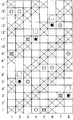
図1,4,7,10,13,16,19,22,25,28,31は、本発明の実施例の完全組織を示す意匠図である。完全組織とは、織物組織の最小の繰り返し単位であって、この完全組織が上下左右につながって織物全体の組織が形成される。意匠図において、経糸はアラビア数字、例えば1,2,3で示し、緯糸はダッシュを付したアラビア数字、例えば1’,2’,3’で示す。
また、×印は上層面側経糸が上層面側緯糸の上側に、または経地糸接結糸が上層面側緯糸の上側に位置していることを示し、○印は下層面側経糸が下層面側緯糸の下側に、または経地糸接結糸が下層面側緯糸の下側に位置していることを示し、□印は経地糸接結糸が上層面側緯糸の上側に位置していることを示し、●印は経地糸接結糸が下層面側緯糸の下側に位置していることを示す。
上層面側と下層面側の経糸、緯糸は上下に重なって配置されている。尚、意匠図では糸が上下に正確に重なって上層面側の経糸、緯糸の真下に下層面側の経糸、緯糸が配置されることになっているが、これは図面の都合上であって実際の織物ではずれて配置されても構わないものである。
Embodiments of the present invention will be described with reference to the drawings.
1, 4, 7, 10, 13, 16, 19, 22, 25, 28, 31 are design diagrams showing the complete organization of the embodiments of the present invention. The complete structure is a minimum repeating unit of the woven structure, and this complete structure is connected vertically and horizontally to form the entire structure of the woven fabric. In the design drawing, warps are indicated by Arabic numerals, for example 1, 2, 3, and wefts are indicated by Arabic numerals with dashes, for example, 1 ′, 2 ′, 3 ′.
The x mark indicates that the upper surface side warp is located above the upper surface side weft, or the warp binding yarn is located above the upper surface side weft, and the ○ mark indicates that the lower surface side warp is below Indicates that the warp binding yarn is located below the layer side weft, or below the lower surface weft, and the □ mark indicates that the warp binding yarn is located above the upper surface weft. The ● mark indicates that the warp binding yarn is located on the lower side of the lower surface side weft.
The upper surface side and lower surface side warps and wefts are arranged one above the other. In the design drawing, the upper and lower warp yarns are arranged so that the yarns are accurately overlapped vertically, and the lower surface warp and the weft yarn are arranged just below the weft yarn. In an actual fabric, it may be displaced.
実施例1
図1は本発明の実施例1の完全組織を示す意匠図である。
図1の意匠図において8組の上下に配置された上層面側経糸と下層面側経糸の組のうち1,3,5,7は上層面側表面を形成する上層面側経糸と、下層面側表面を形成する下層面側経糸が上下に配置された組であり、2,4,6,8は上層面側緯糸および下層面側緯糸と織り合わされて上層面側表面組織の一部と下層面側表面組織の一部を形成する2本の経地糸接結糸の組である。1’,2’,3’・・・16’は上層面側緯糸および下層面側緯糸を示し下層面側緯糸は上層面側緯糸の半分の密度で奇数番号の上層面側緯糸の1’,3’,5’・・・15’の下側に配置している。経地糸接結糸は上層面側層と下層面側層を織り合わせる糸であり、上層面側表面組織と下層面側表面組織を互いに補完し合って各々の表面組織を形成しているため表面組織を崩さない。2本の経地糸接結糸の組と上層面側経糸と下層面側経糸の組が1本交互に配置している。また、下層面側緯糸は上層面側緯糸の半分の比率で配置している。
下層面側経糸は連続する4本の下層面側緯糸の上側を通り、次いで1本の下層面側緯糸の下側を通り、次いで連続する2本の下層面側緯糸の上側を通り、次いで1本の下層面側緯糸の下側を通る4/1-2/1組織であり、下層面側経糸1は連続する4本の下層面側緯糸1’,3’,5’,7’の上側を通り、次いで1本の下層面側緯糸9’の下側を通り、次いで連続する2本の下層面側緯糸11’,13’の上側を通り、次いで1本の下層面側緯糸15’の下側を通る組織であることがわかる。
Example 1
FIG. 1 is a design diagram showing the complete structure of Example 1 of the present invention.
In the design diagram of FIG. 1, among the upper and lower surface side warp and lower surface side warp pairs arranged at the top and bottom, 1, 3, 5, and 7 are the upper surface side warp and the lower surface that form the upper surface side surface. The lower surface warp forming the side surface is a set arranged vertically, and 2, 4, 6, and 8 are interwoven with the upper surface side weft and the lower surface side weft, and a part of the upper surface surface texture and the lower surface It is a set of two warp binding yarns that form a part of the layer side surface texture. 1 ′, 2 ′, 3 ′... 16 ′ indicate upper surface side wefts and lower surface side wefts, and lower surface side wefts are half the density of upper surface side wefts and are 1 ′ of odd number upper surface side wefts. 3 ′, 5 ′... 15 ′ are arranged below. The warp binding yarn is a yarn that interweaves the upper layer side layer and the lower layer side layer, and the upper layer surface structure and the lower layer surface structure complement each other to form each surface structure. Does not disrupt the surface texture. Two warp binding yarn pairs, one upper surface side warp and one lower surface side warp group are alternately arranged. Further, the lower surface side wefts are arranged at a ratio of half of the upper surface side wefts.
The lower surface warp passes through the upper side of four consecutive lower surface side wefts, then passes the lower side of one lower surface side weft, then passes the upper side of two consecutive lower surface side wefts, then 1 The lower
組になった経地糸接結糸が、一方の経地糸接結糸が少なくとも1本の上層面側緯糸と織り合わされ上層面側表面組織を形成しているところの下側で、もう一方の経地糸接結糸が1本の下層面側緯糸と織り合わされ、且つ、一方の経地糸接結糸が1本の下層面側緯糸と織り合わされているところの上側で、もう一方の経地糸接結糸が少なくとも1本の上層面側緯糸と織り合わされ上層面側表面組織を形成し、それらが協働して上層面側完全組織を構成する1本の経糸として機能し、下層面側表面組織は下層面側経糸が形成する4/1−2/1組織と同じ組織となり、組になった経地糸接結糸2が、一方の経地糸接結糸が上層面側緯糸5’,6’と織り合わされているところの下側で、もう一方の経地糸接結糸が1本の下層面側緯糸5’と織り合わされ、且つ、一方の経地糸接結糸が1本の下層面側緯糸15’と織り合わされているところの上側で、もう一方の経地糸接結糸が上層面側緯糸9’,10’,13’,14’,1’,2’と織り合わされる組織とすることで、下層面側表面組織は4/1-2/1組織を、上層面側表面組織は2/2組織を形成し、1組の経地糸接結糸が上層面側表面組織と下層面側表面組織を互いに補完し合って各々の表面組織を形成する。例えば、経地糸接結糸2の一方は、上層面側緯糸1’、2’の上側を通り、次いで上層面側緯糸3’、4’と下層面側緯糸の間を通り、次いで下層面側緯糸5エの下側を通り、次いで上層面側緯糸6’、7’、8’と下層面側緯糸の間を通り、次いで上層面側緯糸9’、10’の上側を通り、次いで上層面側緯糸11’、12’と下層面側緯糸の間を通り、次いで上層面側緯糸13’、14’の上側を通り、次いで上層面側緯糸15’、16’と下層面側緯糸の間を通る組織を形成している。また、もう一方は、上層面側緯糸1’〜4’下層面側緯糸の間を通り、次いで上層面側緯糸5’、6’の上側を通り、次いで上層面側緯糸7’〜14’と下層面側緯糸の間を通り、次いで下層面側緯糸15’の下側を通り、次いで上層面側緯糸16’と下層面側緯糸の間を通る組織を形成している。この組となった2本の経地糸接結糸は協働して、上層面側表面組織は連続する2本の上層面側緯糸の上を通り、次に連続する2本の上層面側緯糸の下側を通る2/2組織を形成し、下層面側表面組織は連続する4本の下層面側緯糸の上側を通り、次いで1本の下層面側緯糸の下側を通り、次いで連続する2本の下層面側緯糸の上側を通り、次いで1本の下層面側緯糸の下側を通る4/1−2/1組織を形成する。上層面側表面組織は他の上層面側経糸と上層面側緯糸が形成する2/2組織と同じであり、また下層面側表面組織は他の下層面側経糸と下層面側緯糸が形成する4/1−2/1組織と同じ組織である。
本実施例では、経地糸接結糸2は、下層面側経糸1を下層面側緯糸3本分シフトして配置している。その隣の下層面側経糸3は、経地糸接結糸2を下層面側緯糸3本分シフトして配置している。これを順次繰り返して配置することにより、隣り合う2本の下層面側経糸と経地糸接結糸が1本の下層面側緯糸を下層面側から同時に織り込むことで織物剛性が向上し、また、下層面側緯糸により下層面側表面に下層面側経糸6本分の緯糸ロングクリンプが形成されるため、耐摩耗性が向上する。
A pair of warp binding yarns in a pair is below the one where one warp binding yarn is interwoven with at least one upper surface side weft to form an upper surface side surface structure. The warp binding yarn is interwoven with one lower surface side weft, and the upper side where one warp binding yarn is interwoven with one lower surface side weft, the other The warp binding yarns are interwoven with at least one upper surface side weft to form an upper surface side surface structure, which function together as one warp to form the upper surface side complete structure, The layer surface side surface structure is the same as the 4 / 1-2 / 1 structure formed by the lower surface side warp, and the
In this embodiment, the
隣接する下層面側経糸1、経地糸接結糸2をそれぞれ下層面側緯糸3本分ずらして順次配置する繰り返しにより、隣り合う2本の下層面側経糸1と経地糸接結糸2が1本の下層面側緯糸15’を下層面側から同時に隣接して織り込むことで、下層面側緯糸15’は2本の下層面側経糸1,経地糸接結糸2の上側を通り、次いで連続する6本の下層面側経糸3,5,7,経地糸接結糸4,6,8の下側を通る組織になることがわかる。
下層面側緯糸が隣り合う下層面側経糸と経地糸接結糸を同時に織り込むことでその下層面側経糸と経地糸接結糸は寄り合う。下層面側経糸および経地糸接結糸は下層面側緯糸に2回織り込まれ、下層面側経糸はそのうち1回ずつ左右の隣り合う経地糸接結糸と同時に織り込まれるため、下層面側経糸は交互に隣接しながらジグザグに配置される。経地糸接結糸も1回ずつ左右の隣り合う下層面側経糸と同時に織り込まれるため、経地糸接結糸は交互に隣接しながらジグザグに配置される。したがって、下層面側層を構成する経方向の糸はジグザグに配置される。
Two adjacent lower surface side warps 1 and warp
When the lower surface warp and the warp binding yarn are woven simultaneously, the lower surface warp and the warp binding yarn come close to each other. Lower surface side warp and warp binding yarn are woven twice into lower surface side weft, and lower surface side warp is woven together with the left and right adjacent warp binding yarns on the lower surface side. The warps are arranged in a zigzag while being alternately adjacent. Since the warp binding yarns are woven simultaneously with the left and right adjacent lower surface side warps one by one, the warp binding yarns are arranged in a zigzag while being alternately adjacent. Accordingly, the warp direction yarns constituting the lower surface side layer are arranged in a zigzag manner.
上記のジグザグ配置について下層面側経糸3と経地糸接結糸4を例に挙げて説明する。
経地糸接結糸2と下層面側経糸3は下層面側緯糸5’により同時に織り込まれることで、経地糸接結糸2と下層面側経糸3は互いに寄り合い、そして、下層面側経糸3と経地糸接結糸4は下層面側緯糸11’により同時に織り込まれることで下層面側経糸3と経地糸接結糸4は互いに寄り合う。そのため下層面側経糸3は下層面側緯糸5´との交点で経地糸接結糸2と寄り合い、下層面側の緯糸11´との交点で経地糸接結糸4と寄り合い、これが繰り返されることによって下層面側経糸はジグザクに配置されることがわかる。
そして、経地糸接結糸4については、経地糸接結糸4と下層面側経糸5は下層面側緯糸1’により同時に織り込まれることで、経地糸接結糸4と下層面側経糸5は互いに寄り合い、そして、下層面側経糸3と経地糸接結糸4は下層面側緯糸11’により同時に織り込まれることで、下層面側経糸3と経地糸接結糸4は互いに寄り合う。そのため経地糸接結糸4は下層面側緯糸1´との交点で下層面側経糸3と寄り合い、下層面側の緯糸11´との交点で下層面側経糸5と寄り合い、これが繰り返されることによって下層面側経糸はジグザクに配置されることがわかる。その他の下層面側経糸、経地糸接結糸も同様に交互に隣接しながらジグザグに配置され、下層面側層を構成する経方向の糸はジグザグに配置されることがわかる。このような配置をすることにより上層面側層を構成する経方向の糸と下層面側層を構成する経方向の糸の重なる部分と重ならない部分が混在し、ろ水性が不均一になり段階的に脱水させることで脱水マークの発生、ワイヤー上のシート原料の刺さり込み、繊維や填料等の抜けを抑制したり、斜め方向の剛性を向上させる。
上層面側層をみてみると、上層面側経糸は、連続する2本の上層面側緯糸の上側を通り、次に連続する2本の上層面側緯糸の下側を通る2/2の組織であり、隣りの経地糸接結糸は上層面側経糸を上層面側緯糸1本分ずらして順次配置する繰り返しにより形成している。上層面側経糸1では連続する2本の上層面側緯糸4’,5’の上側を通り、次に連続する2本の上層面側緯糸6’,7’の下側を通る、これを繰り返した2/2組織であることがわかる。また、組になった経地糸接結糸2により形成される上層面側表面組織は、同様に2/2組織とした。その他の上層面側経糸、経地糸接結糸も同様に2/2組織を形成する。このような上層面側経糸が形成する上層面側表面組織と経地糸接結糸が形成する上層面側表面組織を同じ組織にすることで均一な表面を形成することができる。本実施例では、上層面側層を2/2組織としたが、特に限定されず適宜選択できる。
上記に述べたような本発明の組織とすることで、織物の剛性、斜め剛性、耐摩耗性、表面性を向上し、脱水マークの発生、ワイヤー上のシート原料の刺さり込み、繊維や填料等の抜けを抑制できる織物となる。
The above zigzag arrangement will be described by taking the lower
The
For the
Looking at the upper layer side layer, the upper layer side warp passes through the upper side of two continuous upper layer side wefts and then passes through the lower side of the two consecutive upper layer side wefts. The adjacent warp binding yarns are formed by repeatedly arranging the upper surface side warp by shifting one upper surface side weft. The upper
By using the structure of the present invention as described above, the rigidity, oblique rigidity, abrasion resistance, and surface properties of the fabric are improved, the generation of dehydration marks, the insertion of sheet material on the wire, fibers, fillers, etc. It becomes a woven fabric that can suppress the slipping out.
実施例2
図4は本発明の実施例2の完全組織を示す意匠図である。
図4の意匠図において8組の上下に配置された上層面側経糸と下層面側経糸の組のうち1,3,4,5,7,8を上層面側経糸および下層面側経糸の組とし、2,6を経地糸接結糸の組とした。2本の経地糸接結糸の組と上層面側経糸と下層面側経糸の組が1:3の割合で配置している。上層面側緯糸と下層面側緯糸は3:2の割合で配置している。実施例1と同様に経地糸接結糸は上層面側層と下層面側層を織り合わせる糸であり、1組の経地糸接結糸は上層面側表面組織と下層面側表面組織を互いに補完し合っているために表面組織を崩さない。上層面側層を平織組織としたことで、実施例1に比べると上層面側表面はより緻密になり、織物の剛性、斜め剛性、表面性が向上し、脱水マークの発生、ワイヤー上のシート原料の刺さり込み、繊維や填料等の抜けを抑制することができる。
Example 2
FIG. 4 is a design diagram showing the complete structure of Example 2 of the present invention.
In the design diagram of FIG. 4, eight sets of upper layer side warp and lower layer side warp arranged at the top and bottom are set to 1, 3, 4, 5, 7, 8 as upper layer side warp and lower layer side warp groups. 2 and 6 were set as warp binding yarns. A pair of two warp binding yarns, an upper surface side warp and a lower surface side warp are arranged in a ratio of 1: 3. The upper surface side weft and the lower surface side weft are arranged in a ratio of 3: 2. As in Example 1, the warp binding yarn is a yarn that interweaves the upper layer side layer and the lower layer side layer, and one set of warp binding yarns consists of the upper layer surface texture and the lower layer surface texture. Since they complement each other, the surface texture is not destroyed. By making the upper layer side layer a plain weave structure, the upper layer surface is more dense than in Example 1, and the rigidity, oblique rigidity and surface properties of the fabric are improved, the generation of dehydration marks, the sheet on the wire Raw material stabs, fibers and fillers can be prevented from coming off.
実施例3
図7は本発明の実施例3の完全組織を示す意匠図である。
図7の意匠図において8組の上下に配置された上層面側経糸と下層面側経糸の組のうち1,3,4,5,7,8を上層面側経糸および下層面側経糸の組とし、2,6を経地糸接結糸の組とした。2本の経地糸接結糸の組と上層面側経糸と下層面側経糸の組が1:3の割合で配置している。上層面側緯糸と下層面側緯糸は1:1の割合で配置している。上層面側層を1/3組織にしたことで上層面側の緯方向にロングクリンプができるため、繊維支持性が良好になる。また、崩し綾織りにしたことで上層面側表面組織の斜め方向の規則性を崩し、斜め方向のワイヤーマークの発生を抑制することができる。
Example 3
FIG. 7 is a design diagram showing the complete structure of Example 3 of the present invention.
In the design diagram of FIG. 7, among the upper and lower surface side warp and lower surface side warp groups of eight sets, 1, 3, 4, 5, 7, and 8 are the upper surface side warp and lower surface side warp groups. 2 and 6 were set as warp binding yarns. A pair of two warp binding yarns, an upper surface side warp and a lower surface side warp are arranged in a ratio of 1: 3. The upper surface side weft and the lower surface side weft are arranged at a ratio of 1: 1. Since the upper surface side layer has a 1/3 structure, long crimping can be performed in the weft direction on the upper surface side, so that the fiber support is improved. In addition, the broken twill weave breaks the regularity in the oblique direction of the surface structure on the upper layer surface side, thereby suppressing the occurrence of oblique wire marks.
実施例4
図10は本発明の実施例4の完全組織を示す意匠図である。
図10の意匠図において8組の上下に配置された上層面側経糸と下層面側経糸の組のうち1,3,4,5,7,8を上層面側経糸および下層面側経糸の組とし、2,6を経地糸接結糸の組とした。2本の経地糸接結糸の組と上層面側経糸と下層面側経糸の組が1:3の割合で配置している。上層面側緯糸と下層面側緯糸は2:1の割合で配置している。上層面側層を1/3組織にしたことで上層面側の緯方向にロングクリンプができるため、繊維支持性がよい。
Example 4
FIG. 10 is a design diagram showing the complete structure of Example 4 of the present invention.
In the design diagram of FIG. 10, eight sets of upper layer side warp and lower layer side warp arranged at the top and bottom are set to 1, 3, 4, 5, 7, 8 as upper layer side warp and lower layer side warp groups. 2 and 6 were set as warp binding yarns. A pair of two warp binding yarns, an upper surface side warp and a lower surface side warp are arranged in a ratio of 1: 3. The upper surface side weft and the lower surface side weft are arranged in a ratio of 2: 1. Since the upper surface side layer has a 1/3 texture, long crimping can be performed in the weft direction on the upper surface side, so that the fiber support is good.
実施例5
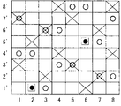
図13は本発明の実施例5の完全組織を示す意匠図である。
図13の意匠図において8組の上下に配置された上層面側経糸と下層面側経糸の組のうち1,3,5,7を上層面側経糸および下層面側経糸の組とし、2,4,6,8を経地糸接結糸の組とした。2本の経地糸接結糸の組と上層面側経糸と下層面側経糸の組が交互に配置している。上層面側緯糸と下層面側緯糸は2:1の割合で配置している。上層面側層を2/2組織にし、さらに崩し綾織りにしたことで上層面側表面組織の斜め方向の規則性を崩し、ワイヤーマークの発生を抑制することができる。
Example 5
FIG. 13 is a design diagram showing the complete structure of Example 5 of the present invention.
In the design diagram of FIG. 13, eight sets of upper and lower surface side warps and lower layer side warp yarns are arranged as upper and lower surface side warps and lower surface side warp pairs, 4, 6, and 8 were used as warp binding yarn pairs. A set of two warp binding yarns, an upper surface side warp and a lower surface side warp are alternately arranged. The upper surface side weft and the lower surface side weft are arranged in a ratio of 2: 1. By making the upper surface side layer into a 2/2 structure and further breaking it into a twill weave, the regularity in the oblique direction of the upper surface surface side surface structure is broken, and the generation of wire marks can be suppressed.
実施例6
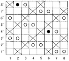
図16は本発明の実施例6の完全組織を示す意匠図である。
図16の意匠図において8組の上下に配置された上層面側経糸と下層面側経糸の組のうち1,3,5,7を上層面側経糸および下層面側経糸の組とし、2,4,6,8を経地糸接結糸の組とした。2本の経地糸接結糸の組と上層面側経糸と下層面側経糸の組が交互に配置している。上層面側緯糸と下層面側緯糸は2:1の割合で配置している。上層面側層の経地糸接結糸は2/2組織を形成し、上層面側経糸は平織組織を形成する、2種類の経糸完全組織からなるものである。経糸完全組織を2種類にすることで上層面側表面組織の斜め方向の規則性を崩し、斜め方向のワイヤーマークの発生を抑制することができる。
Example 6
FIG. 16 is a design diagram showing the complete structure of Example 6 of the present invention.
In the design diagram of FIG. 16, eight sets of upper and lower surface side warps and lower layer side warp yarns are arranged as upper and lower surface side warps and lower surface side warp pairs, 4, 6, and 8 were used as warp binding yarn pairs. A set of two warp binding yarns, an upper surface side warp and a lower surface side warp are alternately arranged. The upper surface side weft and the lower surface side weft are arranged in a ratio of 2: 1. The warp binding yarn of the upper surface side layer forms a 2/2 structure, and the upper surface side warp consists of two types of warp complete structures forming a plain weave structure. By using two types of warp complete structures, the regularity in the oblique direction of the surface structure on the upper layer side can be broken, and the occurrence of wire marks in the oblique direction can be suppressed.
実施例7
図19は本発明の実施例7の完全組織を示す意匠図である。
図19の意匠図において8組の上下に配置された上層面側経糸と下層面側経糸の組のうち1,3,4,5,7,8を上層面側経糸および下層面側経糸の組とし、2,6を経地糸接結糸の組とした。2本の経地糸接結糸の組と上層面側経糸と下層面側経糸の組が1:3の割合で配置している。上層面側緯糸と下層面側緯糸は3:2の割合で配置している。上層面側層を平織組織としたことで、上層面側表面は、実施例1と比べてより緻密になり、織物の剛性、斜め剛性、表面性が向上し、脱水マークの発生、ワイヤー上のシート原料の刺さり込み、繊維や填料等の抜けを抑制することができる。また、本実施例では経地糸接結糸の引き込みが小さく表面性は良好である。例えば、実施例2では経地糸接結糸2は下層面側緯糸1’を下層面側から織り込んでから次の上層面側緯糸3’を織り込むことで上層面側層と下層面側層を接結している。この実施例7では経地糸接結糸2は下層面側緯糸1’を下層面側から織り込んでから次の上層面側緯糸5’を織り込むことで接結しているため、実施例2より上層面側緯糸と下層面側緯糸とを織り込む位置が離れ、緩やかな傾斜で上層面側層と下層面側層を接結しているため、引き込みが実施例2より小さく表面性は良好である。
Example 7
FIG. 19 is a design diagram showing the complete structure of Example 7 of the present invention.
In the design diagram of FIG. 19, eight sets of upper layer side warp and lower layer side warp arranged at the top and bottom are set to 1, 3, 4, 5, 7, 8 as upper layer side warp and lower layer side warp groups. 2 and 6 were set as warp binding yarns. A pair of two warp binding yarns, an upper surface side warp and a lower surface side warp are arranged in a ratio of 1: 3. The upper surface side weft and the lower surface side weft are arranged in a ratio of 3: 2. By making the upper surface side layer into a plain weave structure, the upper surface side surface becomes denser than in Example 1, and the rigidity, oblique rigidity, and surface properties of the fabric are improved, the generation of dehydration marks, It is possible to prevent the sheet raw material from being stabbed and the fibers and fillers from coming off. Further, in this embodiment, the warp binding yarn is not pulled in and the surface property is good. For example, in Example 2, the
実施例8
図22は本発明の実施例8の完全組織を示す意匠図である。
図22の意匠図において8組の上下に配置された上層面側経糸と下層面側経糸の組のうち1,3,4,5,7,8を上層面側経糸および下層面側経糸の組とし、2,6を経地糸接結糸の組とした。2本の経地糸接結糸の組と上層面側経糸と下層面側経糸の組が1:3の割合で配置している。上層面側緯糸と下層面側緯糸は2:1の割合で配置している。上層面側層を3/1組織とし、崩し綾織りにしたことで上層面側表面組織の斜め方向の規則性を崩し、斜め方向のワイヤーマークの発生を抑制することができる。
Example 8
FIG. 22 is a design diagram showing the complete structure of Example 8 of the present invention.
In the design diagram of FIG. 22, eight sets of upper layer side warp and lower layer side warp arranged at the top and bottom are set to 1, 3, 4, 5, 7, 8 as upper layer side warp and lower layer side warp groups. 2 and 6 were set as warp binding yarns. A pair of two warp binding yarns, an upper surface side warp and a lower surface side warp are arranged in a ratio of 1: 3. The upper surface side weft and the lower surface side weft are arranged in a ratio of 2: 1. By making the upper surface side layer a 3/1 structure and making it a twill weave, the regularity in the oblique direction of the upper surface surface side surface structure can be destroyed, and the occurrence of oblique wire marks can be suppressed.
実施例9
図25は本発明の実施例9の完全組織を示す意匠図である。
図25の意匠図において8組の上下に配置された上層面側経糸と下層面側経糸の組のうち1,3,4,5,7,8を上層面側経糸および下層面側経糸の組とし、2,6を経地糸接結糸の組とした。2本の経地糸接結糸の組と上層面側経糸と下層面側経糸の組が1:3の割合で配置している。上層面側緯糸と下層面側緯糸は3:2の割合で配置している。上層面側層を平織組織としたことで、実施例1に比べると上層面側表面はより緻密になり、織物の剛性、斜め剛性、表面性が向上し、脱水マークの発生、ワイヤー上のシート原料の刺さり込み、繊維や填料等の抜けを抑制することができる。
Example 9
FIG. 25 is a design diagram showing the complete structure of Example 9 of the present invention.
In the design diagram of FIG. 25, among the upper and lower surface side warp and lower surface side warp pairs arranged vertically, 1, 3, 4, 5, 7, and 8 are the upper surface side warp and lower surface side warp groups. 2 and 6 were set as warp binding yarns. A pair of two warp binding yarns, an upper surface side warp and a lower surface side warp are arranged in a ratio of 1: 3. The upper surface side weft and the lower surface side weft are arranged in a ratio of 3: 2. By making the upper layer side layer a plain weave structure, the upper layer surface is more dense than in Example 1, and the rigidity, oblique rigidity and surface properties of the fabric are improved, the generation of dehydration marks, the sheet on the wire Raw material stabs, fibers and fillers can be prevented from coming off.
実施例10
図28は本発明の実施例10の完全組織を示す意匠図である。
図28の意匠図において8組の上下に配置された上層面側経糸と下層面側経糸の組のうち、1,3,4,5,7,8を上層面側経糸および下層面側経糸の組とし、2,6を経地糸接結糸と下層面側経糸の組とした。該経地糸接結糸と下層面側経糸の組では、上層面側表面は経地糸接結糸が上層面側緯糸と織り合わされて上層面側完全組織を構成する1本の経糸として機能し、且つ下層面側では経地糸接結糸と下層面側経糸が協働して他の下層面側経糸と同じ下層面側表面組織を形成する。経地糸接結糸と下層面側経糸の組と上層面側経糸と下層面側経糸の組は1:3の割合で配置している。上層面側緯糸と下層面側緯糸は1:1の割合で配置している。実施例1から9まででは、完全組織の中に2本1組にした経地糸接結糸を少なくとも1組配置した織物としたが、本実施例では2本1組にした経地糸接結糸ではなく経地糸接結糸と下層面側経糸の組を2組配置した織物とした。本実施例のような経地糸接結糸と下層面側経糸の配置としても接結力は十分にある。
Example 10
FIG. 28 is a design diagram showing the complete structure of Example 10 of the present invention.
In the design diagram of FIG. 28, among the sets of the upper surface side warp and the lower surface warp arranged in the upper and lower sides, 1, 3, 4, 5, 7, 8 are the upper surface side warp and lower surface side warp. A pair of warp binding yarns and a lower surface warp was used. In the combination of the warp binding yarn and the lower surface warp, the upper surface surface functions as a single warp in which the warp binding yarn is interwoven with the upper surface weft to constitute the upper surface side complete structure. In addition, on the lower surface side, the warp binding yarn and the lower surface warp cooperate to form the same lower surface surface texture as the other lower surface warps. A set of warp binding yarn and lower surface side warp, and upper surface side warp and lower surface side warp are arranged in a ratio of 1: 3. The upper surface side weft and the lower surface side weft are arranged at a ratio of 1: 1. In Examples 1 to 9, a fabric in which at least one pair of warp binding yarns in one set is arranged in a complete structure is used. A woven fabric in which two sets of warp binding yarns and lower surface warp yarns were arranged instead of binding. The binding force is sufficient even when the warp binding yarn and the lower surface warp are arranged as in this embodiment.
実施例11
図31は本発明の実施例12の完全組織を示す意匠図である。
図31の意匠図において8組の上下に配置された上層面側経糸と下層面側経糸の組のうち、1,3,4,5,7,8を上層面側経糸および下層面側経糸の組とし、2,6を経地糸接結糸と上層面側経糸の組とした。該経地糸接結糸と上層面側経糸の組では、上層面側表面は経地糸接結糸と上層面側経糸がそれぞれ別の上層面側緯糸と織り合わされ、それらが協働して上層面側完全組織を構成する1本の経糸として機能し、且つ下層面側では経地糸接結糸が下層面側経糸と同じ下層面側表面組織を形成する。経地糸接結糸と上層面側経糸の組と上層面側経糸と下層面側経糸の組は1:3の割合で配置している。上層面側緯糸と下層面側緯糸は1:1の割合で配置している。本実施例では2本1組にした経地糸接結糸ではなく経地糸接結糸と上層面側経糸の組を2組配置した織物とした。本実施例のような経地糸接結糸と上層面側経糸の配置としても接結力は十分にある。
Example 11
FIG. 31 is a design diagram showing the complete structure of Example 12 of the present invention.
In the design diagram of FIG. 31, among the upper and lower surface side warp and lower surface side warp pairs arranged vertically, 1, 3, 4, 5, 7, and 8 are the upper surface side warp and lower surface side warp. A pair of warp binding yarns and upper surface side warp yarns were used. In the set of warp binding yarn and upper surface side warp, the upper surface side surface is interwoven with warp binding yarn and upper surface side warp with different upper layer side wefts. It functions as a single warp constituting the upper surface side complete structure, and on the lower surface side, the warp binding yarn forms the same lower surface surface structure as the lower surface warp. The set of warp binding yarn and upper surface side warp, and the upper surface side warp and lower surface side warp are arranged in a ratio of 1: 3. The upper surface side weft and the lower surface side weft are arranged at a ratio of 1: 1. In this embodiment, a woven fabric in which two sets of warp binding yarns and upper surface side warp yarns are arranged, not two warp binding yarns. The binding force is sufficient even when the warp binding yarn and the upper surface side warp are arranged as in this embodiment.
本発明は、脱水マークの発生、ワイヤー上の繊維のささり込み、繊維の抜けを防止し、製紙のワイヤーとして優れた利用性を有する。 The present invention prevents the generation of dehydration marks, the fiber on the wire, and the removal of the fiber, and has excellent utility as a papermaking wire.
1,2,3・・・8 上層面側経糸と下層面側経糸の組または経地糸接結糸の組または上層面側経糸と経地糸接結糸の組または下層面側経糸と経地糸接結糸の組
1’,2’・・16’ 上層面側緯糸、下層面側緯糸
1, 2, 3... 8 Upper layer side warp and lower layer side warp pair or warp binding yarn pair or upper layer side warp and warp binding yarn pair or lower surface side warp and warp Ground yarn binding yarn set 1 ', 2', 16 'Upper surface side weft, Lower surface side weft
Claims (11)
Priority Applications (6)
| Application Number | Priority Date | Filing Date | Title |
|---|---|---|---|
| JP2004242258A JP4762513B2 (en) | 2004-08-23 | 2004-08-23 | Industrial two-layer fabric |
| US11/207,942 US7270151B2 (en) | 2004-08-23 | 2005-08-22 | Industrial two-layer fabric |
| EP10182400.1A EP2305865B1 (en) | 2004-08-23 | 2005-08-23 | Industrial two-layer fabric |
| CA 2516882 CA2516882C (en) | 2004-08-23 | 2005-08-23 | Industrial two-layer fabric |
| EP05255174.4A EP1630271B1 (en) | 2004-08-23 | 2005-08-23 | Industrial Two-layer fabric |
| MXPA05008954A MXPA05008954A (en) | 2004-08-23 | 2005-08-23 | Industrial two-layer fabric. |
Applications Claiming Priority (1)
| Application Number | Priority Date | Filing Date | Title |
|---|---|---|---|
| JP2004242258A JP4762513B2 (en) | 2004-08-23 | 2004-08-23 | Industrial two-layer fabric |
Publications (2)
| Publication Number | Publication Date |
|---|---|
| JP2006057217A JP2006057217A (en) | 2006-03-02 |
| JP4762513B2 true JP4762513B2 (en) | 2011-08-31 |
Family
ID=35453491
Family Applications (1)
| Application Number | Title | Priority Date | Filing Date |
|---|---|---|---|
| JP2004242258A Active JP4762513B2 (en) | 2004-08-23 | 2004-08-23 | Industrial two-layer fabric |
Country Status (5)
| Country | Link |
|---|---|
| US (1) | US7270151B2 (en) |
| EP (2) | EP2305865B1 (en) |
| JP (1) | JP4762513B2 (en) |
| CA (1) | CA2516882C (en) |
| MX (1) | MXPA05008954A (en) |
Families Citing this family (24)
| Publication number | Priority date | Publication date | Assignee | Title |
|---|---|---|---|---|
| JP4762529B2 (en) | 2004-11-17 | 2011-08-31 | 日本フイルコン株式会社 | Industrial two-layer fabric |
| JP4440085B2 (en) | 2004-11-26 | 2010-03-24 | 日本フイルコン株式会社 | Industrial two-layer fabric |
| JP4762530B2 (en) | 2004-11-30 | 2011-08-31 | 日本フイルコン株式会社 | Industrial two-layer fabric |
| JP4570090B2 (en) * | 2005-05-19 | 2010-10-27 | 日本フイルコン株式会社 | Industrial two-layer fabric |
| JP4573168B2 (en) * | 2005-05-26 | 2010-11-04 | 日本フイルコン株式会社 | Industrial two-layer fabric |
| JP4684849B2 (en) * | 2005-10-28 | 2011-05-18 | 日本フイルコン株式会社 | Industrial two-layer fabric |
| JP4819477B2 (en) * | 2005-10-31 | 2011-11-24 | 日本フイルコン株式会社 | Industrial two-layer fabric |
| JP4828330B2 (en) * | 2006-07-07 | 2011-11-30 | 日本フイルコン株式会社 | Press fabric for pulp machine |
| JP5281877B2 (en) * | 2008-11-28 | 2013-09-04 | 日本フイルコン株式会社 | Industrial two-layer fabric |
| JP5306788B2 (en) | 2008-11-29 | 2013-10-02 | 日本フイルコン株式会社 | Industrial two-layer fabric |
| EP2230352B1 (en) * | 2009-03-20 | 2012-10-03 | Heimbach GmbH & Co.KG | Woven fabric band for circulation in a machine |
| DE102010031804A1 (en) * | 2010-07-20 | 2012-01-26 | Mahle International Gmbh | Hydraulic filter element and associated manufacturing method |
| JP5777874B2 (en) * | 2010-11-30 | 2015-09-09 | 日本フイルコン株式会社 | Industrial two-layer fabric |
| EP2698458A4 (en) * | 2011-04-11 | 2014-11-12 | Nippon Filcon Kk | Multilayer weave for nonwoven fabric |
| US9150986B2 (en) | 2011-05-04 | 2015-10-06 | Nike, Inc. | Knit component bonding |
| JP2013227701A (en) * | 2012-04-26 | 2013-11-07 | Nippon Filcon Co Ltd | Industrial two-layer fabric |
| JP6280325B2 (en) * | 2013-07-12 | 2018-02-14 | 日本フイルコン株式会社 | Industrial two-layer fabric |
| CA2942562C (en) * | 2015-03-30 | 2023-04-25 | Ikuo Ueda | Industrial two-layer fabric |
| FI128025B (en) * | 2017-03-24 | 2019-08-15 | Valmet Technologies Oy | An industrial textile |
| BR112020009966A2 (en) | 2018-02-12 | 2020-11-03 | Huyck Licensco Inc. | multilayer paper maker training fabric with lower auxiliary md yarns |
| JP7083658B2 (en) * | 2018-02-15 | 2022-06-13 | 日本フイルコン株式会社 | Industrial double-layer woven fabric |
| JP7210785B1 (en) | 2022-01-11 | 2023-01-23 | 日本フイルコン株式会社 | industrial textiles |
| JP7210787B1 (en) | 2022-01-11 | 2023-01-23 | 日本フイルコン株式会社 | industrial textiles |
| JP7210786B1 (en) | 2022-01-11 | 2023-01-23 | 日本フイルコン株式会社 | industrial textiles |
Family Cites Families (19)
| Publication number | Priority date | Publication date | Assignee | Title |
|---|---|---|---|---|
| US4376455A (en) * | 1980-12-29 | 1983-03-15 | Albany International Corp. | Eight harness papermaking fabric |
| DE3301810C2 (en) * | 1983-01-20 | 1986-01-09 | Hermann Wangner Gmbh & Co Kg, 7410 Reutlingen | Composite fabric as a covering for the sheet forming part of a paper machine |
| JP2715097B2 (en) * | 1988-06-09 | 1998-02-16 | 日本フイルコン株式会社 | Weft wear type papermaking fabric |
| CA1320410C (en) * | 1988-06-27 | 1993-07-20 | Takuo Tate | Papermakers' double layer type fabrics |
| US5025839A (en) | 1990-03-29 | 1991-06-25 | Asten Group, Inc. | Two-ply papermakers forming fabric with zig-zagging MD yarns |
| JP3076703B2 (en) * | 1993-09-06 | 2000-08-14 | 日本フイルコン株式会社 | Warp single weft double woven fabric for papermaking |
| JP3444373B2 (en) * | 1994-03-18 | 2003-09-08 | 日本フイルコン株式会社 | Warp double weft double papermaking fabric with auxiliary wefts arranged on the papermaking side fabric |
| JP3883276B2 (en) * | 1997-12-05 | 2007-02-21 | 日本フイルコン株式会社 | Industrial two-layer fabric with auxiliary weft arranged on the upper layer fabric |
| JP2000273740A (en) * | 1999-03-23 | 2000-10-03 | Nippon Filcon Co Ltd | Industrial woven fabric having auxiliary weft yarn arranged in upper layer woven fabric |
| JP3793408B2 (en) * | 2000-09-26 | 2006-07-05 | 日本フイルコン株式会社 | Press fabric for pulp machine |
| DE10123204C2 (en) * | 2001-05-12 | 2003-03-27 | Kufferath Andreas Gmbh | papermaker |
| JP3900037B2 (en) * | 2002-08-01 | 2007-04-04 | 日本フイルコン株式会社 | Industrial two-layer fabric |
| CA2429305C (en) * | 2002-05-24 | 2008-08-05 | Nippon Filcon Co., Ltd. | Industrial two-layer fabric |
| JP3900029B2 (en) * | 2002-07-05 | 2007-04-04 | 日本フイルコン株式会社 | Industrial two-layer fabric |
| JP3938526B2 (en) * | 2002-07-24 | 2007-06-27 | 日本フイルコン株式会社 | Industrial multilayer fabric |
| JP4439977B2 (en) * | 2004-04-09 | 2010-03-24 | 日本フイルコン株式会社 | Industrial two-layer fabric |
| JP4365723B2 (en) * | 2004-04-14 | 2009-11-18 | 日本フイルコン株式会社 | Horizontal belt filter fabric |
| JP4481765B2 (en) * | 2004-08-23 | 2010-06-16 | 日本フイルコン株式会社 | Industrial two-layer fabric |
| JP4400925B2 (en) * | 2004-08-23 | 2010-01-20 | 日本フイルコン株式会社 | Industrial two-layer fabric |
-
2004
- 2004-08-23 JP JP2004242258A patent/JP4762513B2/en active Active
-
2005
- 2005-08-22 US US11/207,942 patent/US7270151B2/en active Active
- 2005-08-23 EP EP10182400.1A patent/EP2305865B1/en active Active
- 2005-08-23 CA CA 2516882 patent/CA2516882C/en active Active
- 2005-08-23 EP EP05255174.4A patent/EP1630271B1/en active Active
- 2005-08-23 MX MXPA05008954A patent/MXPA05008954A/en active IP Right Grant
Also Published As
| Publication number | Publication date |
|---|---|
| EP1630271A2 (en) | 2006-03-01 |
| MXPA05008954A (en) | 2006-02-24 |
| EP2305865A1 (en) | 2011-04-06 |
| US7270151B2 (en) | 2007-09-18 |
| EP1630271A3 (en) | 2006-11-02 |
| CA2516882A1 (en) | 2006-02-23 |
| EP1630271B1 (en) | 2015-12-09 |
| JP2006057217A (en) | 2006-03-02 |
| CA2516882C (en) | 2013-02-19 |
| EP2305865B1 (en) | 2015-12-16 |
| US20060040578A1 (en) | 2006-02-23 |
Similar Documents
| Publication | Publication Date | Title |
|---|---|---|
| JP4762513B2 (en) | Industrial two-layer fabric | |
| JP4762530B2 (en) | Industrial two-layer fabric | |
| JP4819477B2 (en) | Industrial two-layer fabric | |
| JP2006322109A (en) | Industrial two-layered woven fabric | |
| RU2007103770A (en) | THREE-LAYER FORMING FABRICS WITH THE TWIN BASIS AND THE OPTIMAL CHARACTERISTICS OF PAPER SHEET CREATION | |
| JP4739903B2 (en) | Industrial two-layer fabric | |
| JP4762529B2 (en) | Industrial two-layer fabric | |
| JP5777874B2 (en) | Industrial two-layer fabric | |
| JP2006348403A (en) | Double layer woven fabric for industrial use | |
| JP5306788B2 (en) | Industrial two-layer fabric | |
| JP4481765B2 (en) | Industrial two-layer fabric | |
| JP4573168B2 (en) | Industrial two-layer fabric | |
| JP5711946B2 (en) | Industrial two-layer fabric | |
| JP5280160B2 (en) | Industrial multilayer fabric with drawn wefts | |
| JP4570090B2 (en) | Industrial two-layer fabric | |
| JP4684849B2 (en) | Industrial two-layer fabric | |
| JP4896686B2 (en) | Industrial double-layer fabric with longitudinal grooves | |
| JP4841410B2 (en) | Industrial double-layer fabric with longitudinal grooves | |
| US20210148015A1 (en) | Industrial two-layer fabric | |
| MX2009000877A (en) | Dryer fabric. | |
| JP2013501153A (en) | Forming fabric for manufacturing fibrous web materials | |
| CA2733526C (en) | Papermaking fabric, in particular for use in the forming section of a papermaking machine | |
| JP7426304B2 (en) | paper making felt | |
| JP4403058B2 (en) | Method for weaving industrial fabric and endless industrial fabric weaved thereby |
Legal Events
| Date | Code | Title | Description |
|---|---|---|---|
| RD03 | Notification of appointment of power of attorney |
Free format text: JAPANESE INTERMEDIATE CODE: A7423 Effective date: 20060803 |
|
| A621 | Written request for application examination |
Free format text: JAPANESE INTERMEDIATE CODE: A621 Effective date: 20061221 |
|
| A977 | Report on retrieval |
Free format text: JAPANESE INTERMEDIATE CODE: A971007 Effective date: 20090223 |
|
| A131 | Notification of reasons for refusal |
Free format text: JAPANESE INTERMEDIATE CODE: A131 Effective date: 20090309 |
|
| A521 | Request for written amendment filed |
Free format text: JAPANESE INTERMEDIATE CODE: A523 Effective date: 20090507 |
|
| RD01 | Notification of change of attorney |
Free format text: JAPANESE INTERMEDIATE CODE: A7421 Effective date: 20090624 |
|
| A521 | Request for written amendment filed |
Free format text: JAPANESE INTERMEDIATE CODE: A523 Effective date: 20090710 |
|
| A131 | Notification of reasons for refusal |
Free format text: JAPANESE INTERMEDIATE CODE: A131 Effective date: 20100519 |
|
| A521 | Request for written amendment filed |
Free format text: JAPANESE INTERMEDIATE CODE: A523 Effective date: 20100630 |
|
| TRDD | Decision of grant or rejection written | ||
| A01 | Written decision to grant a patent or to grant a registration (utility model) |
Free format text: JAPANESE INTERMEDIATE CODE: A01 Effective date: 20110530 |
|
| A01 | Written decision to grant a patent or to grant a registration (utility model) |
Free format text: JAPANESE INTERMEDIATE CODE: A01 |
|
| A61 | First payment of annual fees (during grant procedure) |
Free format text: JAPANESE INTERMEDIATE CODE: A61 Effective date: 20110608 |
|
| FPAY | Renewal fee payment (event date is renewal date of database) |
Free format text: PAYMENT UNTIL: 20140617 Year of fee payment: 3 |
|
| R150 | Certificate of patent or registration of utility model |
Ref document number: 4762513 Country of ref document: JP Free format text: JAPANESE INTERMEDIATE CODE: R150 Free format text: JAPANESE INTERMEDIATE CODE: R150 |
|
| R250 | Receipt of annual fees |
Free format text: JAPANESE INTERMEDIATE CODE: R250 |
|
| R250 | Receipt of annual fees |
Free format text: JAPANESE INTERMEDIATE CODE: R250 |
|
| R250 | Receipt of annual fees |
Free format text: JAPANESE INTERMEDIATE CODE: R250 |
|
| R250 | Receipt of annual fees |
Free format text: JAPANESE INTERMEDIATE CODE: R250 |
|
| R250 | Receipt of annual fees |
Free format text: JAPANESE INTERMEDIATE CODE: R250 |
|
| R250 | Receipt of annual fees |
Free format text: JAPANESE INTERMEDIATE CODE: R250 |
|
| R250 | Receipt of annual fees |
Free format text: JAPANESE INTERMEDIATE CODE: R250 |
|
| R250 | Receipt of annual fees |
Free format text: JAPANESE INTERMEDIATE CODE: R250 |
|
| R250 | Receipt of annual fees |
Free format text: JAPANESE INTERMEDIATE CODE: R250 |
|
| R250 | Receipt of annual fees |
Free format text: JAPANESE INTERMEDIATE CODE: R250 |