JP4635684B2 - Solar cell abnormality detection device based on vehicle running - Google Patents
Solar cell abnormality detection device based on vehicle running Download PDFInfo
- Publication number
- JP4635684B2 JP4635684B2 JP2005097850A JP2005097850A JP4635684B2 JP 4635684 B2 JP4635684 B2 JP 4635684B2 JP 2005097850 A JP2005097850 A JP 2005097850A JP 2005097850 A JP2005097850 A JP 2005097850A JP 4635684 B2 JP4635684 B2 JP 4635684B2
- Authority
- JP
- Japan
- Prior art keywords
- solar cell
- value
- solar
- illuminance
- abnormality
- Prior art date
- Legal status (The legal status is an assumption and is not a legal conclusion. Google has not performed a legal analysis and makes no representation as to the accuracy of the status listed.)
- Expired - Fee Related
Links
Images


Classifications
-
- Y—GENERAL TAGGING OF NEW TECHNOLOGICAL DEVELOPMENTS; GENERAL TAGGING OF CROSS-SECTIONAL TECHNOLOGIES SPANNING OVER SEVERAL SECTIONS OF THE IPC; TECHNICAL SUBJECTS COVERED BY FORMER USPC CROSS-REFERENCE ART COLLECTIONS [XRACs] AND DIGESTS
- Y02—TECHNOLOGIES OR APPLICATIONS FOR MITIGATION OR ADAPTATION AGAINST CLIMATE CHANGE
- Y02E—REDUCTION OF GREENHOUSE GAS [GHG] EMISSIONS, RELATED TO ENERGY GENERATION, TRANSMISSION OR DISTRIBUTION
- Y02E10/00—Energy generation through renewable energy sources
- Y02E10/50—Photovoltaic [PV] energy
Landscapes
- Photovoltaic Devices (AREA)
Description
本発明は、車輌に搭載される太陽電池の異常を検出する装置に係る。 The present invention relates to an apparatus for detecting an abnormality of a solar cell mounted on a vehicle.
大気環境保全の必要性の高まりに伴って、車輌のエネルギ源として太陽電池を用いることが種々試みられている。太陽電池を車輌のエネルギ源として用いる場合に考慮すべき重要な事項の一つは、太陽電池の発電機能に異常が生じたときには、早急にそれに対処すべく早期にそれを検出することである。このことは、太陽電池が車輌の駆動源に使用される場合には、特に重要である。 With the increasing need for air environment conservation, various attempts have been made to use solar cells as an energy source for vehicles. One of the important matters to be considered when using a solar cell as an energy source of a vehicle is to detect it early in order to deal with it immediately when an abnormality occurs in the power generation function of the solar cell. This is particularly important when solar cells are used as vehicle drive sources.
ところで、太陽電池の出力は、それに当たる太陽光線の強さによって左右されるので、太陽電池の出力に基づいて誤り無くその異常を検出するには、太陽の照り具合が考慮されなければならない。この点に関し、夜間や悪天候時に誤って異常警報が発せられることがないよう、太陽電池の電圧が所定値以下になったとき第一の信号を出力し、外部からの光の受光強度が所定値以下になったとき第二の信号を出力し、第一と第二の信号の出力に応答して警報信号を発するようにすることが下記の特許文献1に記載されている。
太陽電池の発電機能に異常が生じたとき、それを早期に検出するには、太陽電池が昼間の晴天時に直射日光に曝されている状態で、その出力を太陽光線の照射の度合(以下簡単のため太陽照度と云う)に対応した太陽電池の正常時の標準出力に対比させ、その偏差が比較的小さいうちに太陽電池の異常判定を行うことが望まれる。しかし、晴天時の昼間であっても、車輌の場合、その移動性のゆえに、車輌が建物や樹木の陰に駐停車されていたのでは、高い電池出力レベルでの異常判定はできない。 In order to detect an abnormality in the power generation function of a solar cell at an early stage, the solar cell is exposed to direct sunlight when it is sunny in the daytime. Therefore, it is desired to determine whether the solar cell is abnormal or not while the deviation is relatively small. However, even in the daytime in fine weather, in the case of a vehicle, because of its mobility, an abnormality cannot be determined at a high battery output level if the vehicle is parked and parked behind a building or tree.
本発明は、上記の事情に鑑み、発電機能に異常が生じたときにはそれが早期に検出されることが望まれる車輌搭載の太陽電池について、その発電機能の異常を高い電池出力レベルにて早期に検出することができる太陽電池異常検出装置を提供することを課題としている。 In view of the above circumstances, the present invention provides an early detection of abnormality in the power generation function at a high battery output level for a vehicle-mounted solar cell that is desired to be detected at an early stage when an abnormality occurs in the power generation function. It is an object of the present invention to provide a solar cell abnormality detection device that can detect.
上記の課題を解決するものとして、本発明は、車輌に搭載された太陽電池の異常を検出する太陽電池異常検出装置にして、車速が0より大きい所定値以上でないときには前記太陽電池の出力を太陽照度に対比させて前記太陽電池の異常を検出することを行なわないようになっていることを特徴とする太陽電池異常検出装置を提案するものである。 In order to solve the above problems, the present invention provides a solar cell abnormality detection device that detects an abnormality of a solar cell mounted on a vehicle, and outputs the output of the solar cell when the vehicle speed is not equal to or greater than a predetermined value greater than zero. The present invention proposes a solar cell abnormality detection device characterized by not detecting an abnormality of the solar cell in comparison with solar illuminance.
この場合、前記太陽電池の異常検出は太陽照度が所定値以下であるときには行われないようになっていてよい。 In this case, the abnormality detection of the solar cell may not be performed when the solar illuminance is a predetermined value or less.
太陽電池の異常判断は、太陽照度に対応する太陽電池の正常時の標準出力の値に対比して太陽電池の実際の出力の値が所定の偏差以上異なるとき、太陽電池が異常であると判断するものであっていてよい。 A solar cell abnormality is judged to be abnormal when the actual output value of the solar cell differs by more than a predetermined deviation compared to the normal output value of the solar cell corresponding to the solar illuminance. It may be.
前記太陽電池正常時標準出力値と前記太陽電池実際出力値の対比は、所定時間内に於ける各値の平均値について、または所定時間内に於ける各値のピーク値について行われるようになっていていてよい。 The comparison between the standard output value of the normal solar cell and the actual output value of the solar cell is performed with respect to an average value of each value within a predetermined time or a peak value of each value within a predetermined time. It may be.
太陽電池に近接して太陽照度検出手段が配置されているときには、前記太陽電池正常時標準出力値と前記太陽電池実際出力値の対比は同時の値について行われるようになっていてよい。 When the solar illuminance detecting means is disposed in the vicinity of the solar cell, the normal output value at the normal time of the solar cell and the actual output value of the solar cell may be compared with each other at the same time.
車輌に搭載された太陽電池では、昼間の晴天時であっても、車輌が建物や樹木の陰に駐車されていては、太陽電池の出力はさして上がらない。そこで、太陽電池異常検出装置が、車速が0より大きい所定値以上でないときには前記太陽電池出力検出手段により検出された太陽電池の出力を太陽照度に対比させて太陽電池の異常を検出することを行なわないようになっていれば、車輌が建物や樹木の陰に駐車されていている状態に留まることを確実に回避し、太陽電池が昼間の晴天時に直射日光に曝される状態を確保して太陽電池の異常を検出することができる。 In the solar cell mounted on the vehicle, the output of the solar cell does not increase even if the vehicle is parked in the shade of a building or a tree even in fine weather in the daytime. Therefore, the solar cell abnormality detection device, the said output of the solar cell detected by the solar cell output detecting unit in comparison to the solar irradiance to detect an abnormality of the solar cell when the vehicle speed is not larger than 0 or greater than a predetermined value if so as not to take place, the vehicle is reliably avoided that remain in the state that have been parked in the shadow of buildings and trees, to ensure a state in which the solar cell is exposed to direct sunlight during the daytime of fine weather Abnormality of the solar cell can be detected.
太陽電池の異常検出は太陽照度が所定値以下であるときには行われないようにすることにより、太陽電池が昼間の晴天時に直射日光に曝される状態を選んで太陽電池の異常を検出することができる。 By detecting the abnormality of solar cells when the solar illuminance is below a predetermined value, it is possible to detect the abnormality of solar cells by selecting the state in which the solar cells are exposed to direct sunlight during daylight weather. it can.
太陽電池異常検出装置が、太陽照度に対応する太陽電池の正常時の標準出力の値に対比して太陽電池の実際の出力の値が所定の偏差以上異なるとき、太陽電池が異常であると判断することにより、太陽電池の出力異常を太陽電池の正常時の性能に対比して高精度に検出することができる。太陽照度としては、車輌に搭載された光センサの如き太陽照度検出手段により得られる値の他に、多機能カーナビ等により収集された地域天候情報より得られる値が使用されてもよい。自動車等の車輌に従来より既に搭載されているヘッドライトの自動点滅用の光センサを利用することが考えられる。この場合、この種の光センサは、一般にフロントウインドの手前にあるインストルメントパネル上に配置されているので、太陽に対する車輌の向きによっては車輌の屋根の陰になる場合もあるが、車輌が走行していれば、やがては太陽光線の直射を受ける状態となるので、そのような状態を選んで太陽電池の出力を確実にチェックすることができる。 The solar cell abnormality detection device determines that the solar cell is abnormal when the actual output value of the solar cell differs by more than a predetermined deviation from the normal output value of the solar cell corresponding to the solar illuminance. By doing so, the output abnormality of the solar cell can be detected with high accuracy in comparison with the normal performance of the solar cell. As the solar illuminance, a value obtained from local weather information collected by a multifunctional car navigation system may be used in addition to a value obtained by solar illuminance detection means such as an optical sensor mounted on a vehicle. It is conceivable to use a light sensor for automatic blinking of a headlight that has already been mounted on a vehicle such as an automobile. In this case, this type of optical sensor is generally placed on the instrument panel in front of the front window, so depending on the orientation of the vehicle with respect to the sun, it may be behind the roof of the vehicle, but the vehicle is running. If it does, since it will be in the state which receives direct sunlight in time, such a state can be selected and the output of a solar cell can be checked reliably.
太陽電池正常時標準出力値と太陽電池実際出力値の対比が所定時間内に於ける各値の平均値について行われるようになっていれば、車輌の走行に伴って太陽電池対する太陽光線の照射状態が変化しても、それを均して太陽電池の出力性能をチェックすることができる。一方、太陽電池正常時標準出力値と太陽電池実際出力値の対比が所定時間内に於ける各値のピーク値について行われるようになっていれば、車輌が建物の影を横切って走行するよう市街地にて走行しているときにも、建物の陰にならない走行中に太陽電池の性能をチェックすることができる。 If the comparison between the standard output value when the solar cell is normal and the actual output value of the solar cell is performed with respect to the average value of each value within a predetermined time, the solar cell is irradiated with solar rays as the vehicle travels. Even if the state changes, the output performance of the solar cell can be checked by leveling it. On the other hand, if the comparison between the standard output value when the solar cell is normal and the actual output value of the solar cell is performed for the peak value of each value within a predetermined time, the vehicle will run across the shadow of the building. Even when driving in an urban area, the performance of the solar cell can be checked while driving without being hidden behind a building.
上記の如く太陽電池正常時標準出力値と太陽電池実際出力値の対比を所定時間内に於ける各値の平均値について、或いは所定時間内に於ける各値のピーク値について行うことは、太陽照度検出手段としてフロントウインドの手前にあるインストルメントパネル上に配置されているヘッドライトの自動点滅用の光センサを利用するような場合であって、光センサと車輌の天井に配置された太陽電池とが互いに離れて配置されていて、太陽に対する車輌の走行姿勢によっては両者に対する太陽光線の照射状態にかなりの差が出る場合にも有効であるが、太陽電池の異常検出のためにそれ専用の太陽照度検出手段が太陽電池に近接して配置されるような場合には、太陽電池正常時標準出力値と太陽電池実際出力値の対比を同時の値について行うことにより、所定時間内の平均値を求めたりピーク値を選択するような格別の操作を行うことなく太陽電池の状態を随時チェックすることができる。 As described above, the comparison between the standard output value at the normal time of the solar cell and the actual output value of the solar cell is performed on the average value of each value within a predetermined time or on the peak value of each value within the predetermined time. A solar cell disposed on the ceiling of the vehicle in which the light sensor for automatically flashing the headlight disposed on the instrument panel in front of the front window is used as the illuminance detection means. Is effective even when there is a significant difference in the irradiation state of the solar rays depending on the running posture of the vehicle with respect to the sun. When the solar illuminance detection means is placed close to the solar cell, the solar cell normal standard output value and the solar cell actual output value should be compared for the same value. More, it is possible to check at any time the status of the solar cell without performing special operations, such as selecting the peak value or the average value within a predetermined time.
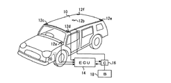
添付の図1は、屋根に太陽電池が搭載され、また太陽照度検出手段として光センサが車輌に搭載されている車輌(自動車)の一例を示す斜視図である。尚、図には光センサがいくつかの設置可能な場所に重複して設置された状態にて示されている。即ち、図に於いて。10は太陽電池であり、12a〜12fはいずれも光センサであるが、光センサ12a〜12fは、いずれか一つが設けられればよいものとする。また、これらの光センサのうち、特に12aはヘッドライトの自動点滅用の光センサとしてインストルメントパネル上に配置されているものであり、本発明による太陽電池異常検出装置に対し利用できるものである。
FIG. 1 attached herewith is a perspective view showing an example of a vehicle (automobile) in which a solar cell is mounted on a roof and an optical sensor is mounted on the vehicle as solar illuminance detection means. In the figure, the optical sensor is shown in a state where it is installed in several places where it can be installed. That is, in the figure. 10 is a solar cell, and 12a to 12f are all optical sensors, but any one of the
14はマイクロコンピュータを組み込んだ車輌の電気式制御装置であり、光センサ12a等により検出された太陽照度に関する情報はこの電気式制御装置へ供給されるようになっている。太陽電池10は充電制御装置16を介してバッテリ18に接続されている。充電制御装置16は電気式制御装置14により制御されるようになっており、また電気式制御装置14は充電制御装置16に於いて太陽電池10の電圧および電流を検出することにより太陽電池の出力を検出するようになっている。また電気式制御装置14には、車速センサ20より車速に関する信号が供給されている。
電気式制御装置14は、車速センサ20からの信号により車輌が0でない或る所定の速度以上にて走行していることが確認されているとき、光センサ12a等からの信号に基づき、マイクロコンピュータによる演算機能によって、太陽照度に対応する太陽電池10の正常時の標準出力の値を算出し,これと充電制御装置16にて検出した太陽電池10の実際の出力の値とを比較し、その間の差が所定の偏差以上であるか否かを検出し、太陽電池10に異常があるか否かを判断する。
When it is confirmed by the signal from the
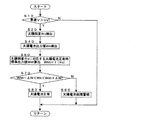
図2はそのような制御プロセスをフローチャートにて表したものである。かかるフローチャートによる制御は、図には示されていない車輌のイグニッションスイッチが閉じられることにより車輌の運転が開始されると、車輌の運転中数10〜数100ミリセカンドの周期にて繰り返される。 FIG. 2 is a flowchart showing such a control process. The control according to the flowchart is repeated at a cycle of several tens to several hundreds of milliseconds during the operation of the vehicle when the vehicle operation is started by closing an ignition switch of the vehicle not shown in the drawing.
制御が開始されると、ステップ10にて車速Vが0でない或る所定の車速Vaより大きいか否かが判断される。答えがノーであれば、この回の制御はこれにて終了するが、答えがイエス(Y)であれば、制御はステップ20へ進み、太陽照度Rsが検出される。太陽照度は、図1に例示したように車輌に搭載された光センサの如き太陽照度検出手段により得られる値の他に、多機能カーナビ等により収集された地域天候情報より得られる値が使用されてよい。尚、太陽照度として後者の値が使用されるときには、後述の下限値Rsmo,Wsmo,Rspo,Wspo,Rsro,Wsroを適切な大きさの値に設定することにより、太陽電池の異常検出が確実に晴天時の直射日光の下で行われるようにし、これによって太陽電池の異常検出を誤り無く行わせることができる。次いで制御はステップ40へ進み、太陽電池の出力値Wsが検出される。次いで制御はステップ60へ進み、太陽照度Rsに対応する太陽電池の正常時の標準出力値WsnがRsの関数f(Rs)として算出される。この演算は予め設定されたRsに対応するWsnをグラフにしたマップをRsの値に基づいて読み取ることにより行われてよい。
When the control is started, it is determined in
次いで制御はステップ70へ進み、Wsの値がWsn+ΔWsとWsn−ΔWsの間にあるか否かが判断される。答はイエスであれば、制御はステップ80へ進み、太陽電池は正常であると判断されるが、答がノー(N)であれば、制御はステップ90へ進み、太陽電池に異常があることを知らせる警報が発生られる。 Control then proceeds to step 70 where it is determined whether the value of Ws is between Wsn + ΔWs and Wsn− ΔWs. If the answer is yes, control proceeds to step 80 and the solar cell is determined to be normal, but if the answer is no (N) , control proceeds to step 90 and the solar cell is abnormal. An alarm is generated to notify you.
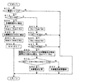
図3は、太陽電池正常時標準出力値と太陽電池実際出力値の対比を所定時間内に於ける各値の平均値について行う場合の一例を示す図2と同様のフローチャートである。図3に於いて、図2に示すステップに対応するステップは図2に於けると同じステップ番号により示されている。 FIG. 3 is a flowchart similar to FIG. 2 showing an example in which the comparison between the standard output value at the normal time of the solar cell and the actual output value of the solar cell is performed for the average value of each value within a predetermined time. In FIG. 3, steps corresponding to the steps shown in FIG. 2 are indicated by the same step numbers as in FIG.
この場合、ステップ10の答がイエスのときには、制御はステップ15へ進み、後述のステップ50に於いて初期値0より始まってアップカウントされるサイクル回数の値Nが上記の平均値を求める所定時間の経過に対応するカウント値Nmを越えたか否かが判断される。答がノーの間、制御はステップ20へ進む。
In this case, when the answer to step 10 is yes, the control proceeds to step 15, and the value N of the number of cycles that starts counting from the initial value 0 in
ステップ20に於いては、各サイクルに於ける太陽照度の値Rsiが検出され、これらの値が、ステップ21に於いて、積算値Rsmとして初期値0から始まって順次積算される。かかる詳細な太陽照度値Rsiとしては、図1に例示したように車輌に搭載された光センサの如き太陽照度検出装置により得られたものが望ましい。ステップ40に於いては、各サイクルに於ける太陽電池出力の値Wsiが検出され、これらの値が、ステップ41に於いて、積算値Wsmとして初期値0から始まって順次積算される。
In
ステップ50に於いては、サイクル回数のカウント値Nが初期値0より始まってアップカウントされる
In
上記の所定時間が経過してステップ15の答がノーからイエスに転ずると、制御はステップ51へ進み、積算値Rsmをカウント値Nmで割って太陽照度の平均値Rsが算出される。次いで、制御はステップ53へ進み、算出された太陽照度の平均値Rsが或る所定の下限値Rsmoより大きいか否かが判断される。この場合、Rsmoは、太陽照度の平均値がこれ以下であるような天候状態では、この制御態様による太陽電池の異常検出は行わないものとするための太陽照度の下限値である。答がイエスであれば、制御はステップ55へ進むが、答がノーであれば、制御はこれよりそのままリターンする。 When the above predetermined time has elapsed and the answer to step 15 turns from no to yes, the control proceeds to step 51, and the integrated value Rsm is divided by the count value Nm to calculate the average value Rs of solar illuminance. Next, control proceeds to step 53, where it is determined whether or not the calculated average value Rs of solar illuminance is greater than a certain predetermined lower limit value Rsmo. In this case, Rsmo is a lower limit value of the solar illuminance for not detecting the abnormality of the solar cell by this control mode in a weather state where the average value of the solar illuminance is less than this. If the answer is yes, control proceeds to step 55, but if the answer is no, control returns directly.
ステップ55に於いては、積算値Wsmをカウント値Nmで割って太陽電池出力の平均値Wsが算出される。次いで、制御はステップ57へ進み、算出された太陽電池出力の平均値Wsが或る所定の下限値Wsmoより大きいか否かが判断される。この場合にも、Wsmoは、太陽電池出力の平均値がこれ以下であるような天候状態では、この制御態様による太陽電池の異常検出は行わないものとするための太陽電池出力の下限値である。答がイエスであれば、制御はステップ60へ進むが、答がノーであれば、制御はこれよりそのままリターンする。以下のステップ60、70、80、90による制御は、図2のフローチャートに於けると同じである。
In
図4は、太陽電池正常時標準出力値と太陽電池実際出力値の対比を所定時間内に於ける各値のピーク値について行う場合の一例を示す図2および図3と同様のフローチャートである。図4に於いても、図2および図3に示すステップに対応するステップは図2および図3に於けると同じステップ番号により示されている。 FIG. 4 is a flowchart similar to FIG. 2 and FIG. 3 showing an example in which the comparison between the solar cell normal standard output value and the solar cell actual output value is performed for the peak value of each value within a predetermined time. In FIG. 4, steps corresponding to the steps shown in FIGS. 2 and 3 are indicated by the same step numbers as in FIGS.
この場合にも、ステップ10の答がイエスのときには、制御はステップ15へ進み、ステップ50に於いて初期値0より始まってアップカウントされるサイクル回数のカウント値Nが上記のピーク値を求める所定時間の経過に対応するカウント値Npを越えたか否かが判断される。答がノーの間、制御はステップ20へ進む。
Also in this case, if the answer to step 10 is yes, the control proceeds to step 15 where the count value N of the number of cycles up-counted starting from the initial value 0 in
ステップ20に於いては、各サイクルに於ける太陽照度の値Rsiが検出され、次いでステップ22に於いて、今回のサイクルに於ける検出値Rsi(N)の値が前回のサイクルに於ける検出値Rsi(N-1)より大きいか否かが判断される。答がイエスであれば、制御はステップ24へ進み、今回の検出値Rsi(N)が太陽照度のピーク値Rsとされ、答がノーの時には、制御はステップ26へ進み、前回の検出値Rsi(N-1)が太陽照度のピーク値Rsとされる。こうして所定期間内に於ける太陽照度のピーク値が求められる。いずれの場合にも制御は次いでステップ40へ進む。
In
ステップ40に於いては、各サイクルに於ける太陽電池出力の値Wsiが検出され、次いでステップ42に於いて、今回のサイクルに於ける検出値Wsi(N)の値が前回のサイクルに於ける検出値Wsi(N-1)より大きいか否かが判断される。答がイエスであれば、制御はステップ44へ進み、今回の検出値Wsi(N)が太陽照度のピーク値Wsとされ、答がノーの時には、制御はステップ46へ進み、前回の検出値Wsi(N-1)が太陽照度のピーク値Wsとされる。こうして所定期間内に於ける太陽電池出力のピーク値が求められる。いずれの場合にも制御は次いでステップ50へ進む。
In
上記の所定時間が経過してステップ15の答がノーからイエスに転ずると、制御はステップ52へ進み、算出された太陽照度のピーク値Rsが或る所定の下限値Rspoより大きいか否かが判断される。この場合にも、Rspoは、太陽照度のピーク値がこれ以下であるような天候状態では、この制御態様による太陽電池の異常検出は行わないものとするための太陽照度の下限値である。答がイエスであれば、制御はステップ54へ進むが、答がノーであれば、制御はこれよりそのままリターンする。 When the above predetermined time has elapsed and the answer to step 15 turns from no to yes, the control proceeds to step 52 where it is determined whether or not the calculated peak value Rs of solar illuminance is greater than a certain predetermined lower limit value Rspo. To be judged. Also in this case, Rspo is a lower limit value of the solar illuminance for not detecting the abnormality of the solar cell by this control mode in a weather state where the peak value of the solar illuminance is lower than this. If the answer is yes, control proceeds to step 54, but if the answer is no, control returns directly.
ステップ54に於いては、算出された太陽電池出力のピーク値Wsが或る所定の下限値Wspoより大きいか否かが判断される。この場合にも、Wspoは、太陽電池出力のピーク値がこれ以下であるような天候状態では、この制御態様による太陽電池の異常検出は行わないものとするための太陽電池出力の下限値である。答がイエスであれば、制御はステップ60へ進むが、答がノーであれば、制御はこれよりそのままリターンする。以下のステップ60、70、80、90による制御は、図2および図3のフローチャートに於けると同じである。
In
図5は、太陽電池に近接して上記の光センサ12b〜12fの如き太陽照度検出手段が配置されている場合に、太陽電池正常時標準出力値と太陽電池実際出力値の対比を同時の値について行う一例を示す図2〜図4と同様のフローチャートである。図5に於いても、図2〜図4に示すステップに対応するステップは図2〜図4に於けると同じステップ番号により示されている。
FIG. 5 shows a comparison between the solar cell normal output value and the solar cell actual output value at the same time when solar illuminance detection means such as the above-described
この場合には、ステップ10の答がイエスのときには、制御はステップ20へ進み、各サイクルに於ける太陽照度の値Rsiが検出され、次いでステップ28に於いて、Rsiの値が或る所定の下限値Rsroより大きいか否かが判断される。この場合にも、Rsroは、各サイクル時点に於ける太陽照度がこれ以下であるような天候状態では、この制御態様による太陽電池の異常検出は行わないものとするための太陽照度の下限値である。答がイエスであれば、制御はステップ40へ進むが、答がノーであれば、制御はこれよりそのままリターンする。 In this case, if the answer to step 10 is yes, control proceeds to step 20 where the solar illuminance value Rsi in each cycle is detected, and then in step 28 the value of Rsi is a predetermined value. It is determined whether or not it is larger than the lower limit value Rsro. Also in this case, Rsro is the lower limit value of the solar illuminance so that the solar cell abnormality detection according to this control mode is not performed in the weather state where the solar illuminance at each cycle time is lower than this. is there. If the answer is yes, control proceeds to step 40, but if the answer is no, control returns directly.
ステップ40に於いては、各サイクルに於ける太陽電池出力の値Wsiが検出され、次いでステップ48に於いて、Wsiの値が或る所定の下限値Wsroより大きいか否かが判断される。この場合にも、Wsroは、各サイクル時点に於ける太陽電池出力がこれ以下であるような天候状態では、この制御態様による太陽電池の異常検出は行わないものとするための太陽電池出力の下限値である。答がイエスであれば、制御はステップ60へ進むが、答がノーであれば、制御はこれよりそのままリターンする。以下のステップ60、70、80、90による制御は、図2〜図4のフローチャートに於けると同じである。
In
以上に於いては本発明をいくつかの実施の形態について詳細に説明したが、これらの実施の形態について本発明の範囲内にて種々の変更が可能であることは当業者にとって明らかであろう。 While the present invention has been described in detail with respect to several embodiments thereof, it will be apparent to those skilled in the art that various modifications can be made to these embodiments within the scope of the present invention. .
10…太陽電池、12a〜12f…光センサ、14…電気式制御装置、16…充電制御装置、18…バッテリ、20…車速センサ
DESCRIPTION OF
Claims (6)
Priority Applications (1)
| Application Number | Priority Date | Filing Date | Title |
|---|---|---|---|
| JP2005097850A JP4635684B2 (en) | 2005-03-30 | 2005-03-30 | Solar cell abnormality detection device based on vehicle running |
Applications Claiming Priority (1)
| Application Number | Priority Date | Filing Date | Title |
|---|---|---|---|
| JP2005097850A JP4635684B2 (en) | 2005-03-30 | 2005-03-30 | Solar cell abnormality detection device based on vehicle running |
Publications (2)
| Publication Number | Publication Date |
|---|---|
| JP2006273211A JP2006273211A (en) | 2006-10-12 |
| JP4635684B2 true JP4635684B2 (en) | 2011-02-23 |
Family
ID=37208355
Family Applications (1)
| Application Number | Title | Priority Date | Filing Date |
|---|---|---|---|
| JP2005097850A Expired - Fee Related JP4635684B2 (en) | 2005-03-30 | 2005-03-30 | Solar cell abnormality detection device based on vehicle running |
Country Status (1)
| Country | Link |
|---|---|
| JP (1) | JP4635684B2 (en) |
Families Citing this family (4)
| Publication number | Priority date | Publication date | Assignee | Title |
|---|---|---|---|---|
| JP5800069B2 (en) * | 2014-07-10 | 2015-10-28 | ダイキン工業株式会社 | Diagnostic device, diagnostic method, and solar power generation system for solar power generation unit |
| JP6408280B2 (en) * | 2014-07-29 | 2018-10-17 | 京セラ株式会社 | Solar cell abnormality detection method and power management apparatus |
| JP6852643B2 (en) * | 2017-10-16 | 2021-03-31 | トヨタ自動車株式会社 | Solar system abnormality judgment device |
| JP2020156135A (en) * | 2019-03-18 | 2020-09-24 | トヨタ自動車株式会社 | vehicle |
Citations (4)
| Publication number | Priority date | Publication date | Assignee | Title |
|---|---|---|---|---|
| JPH01135078A (en) * | 1987-11-20 | 1989-05-26 | Mazda Motor Corp | Function diagnostic apparatus for solar cell |
| JPH11240429A (en) * | 1998-02-24 | 1999-09-07 | Toshiba Corp | Data analysis communication unit, data analysis communication method, and media recorded with data analysis communication program |
| JP2001326375A (en) * | 2000-03-10 | 2001-11-22 | Sanyo Electric Co Ltd | Method and apparatus for diagnosis of solar light power generation system |
| JP2004260015A (en) * | 2003-02-26 | 2004-09-16 | Kyocera Corp | Solar power generator |
-
2005
- 2005-03-30 JP JP2005097850A patent/JP4635684B2/en not_active Expired - Fee Related
Patent Citations (4)
| Publication number | Priority date | Publication date | Assignee | Title |
|---|---|---|---|---|
| JPH01135078A (en) * | 1987-11-20 | 1989-05-26 | Mazda Motor Corp | Function diagnostic apparatus for solar cell |
| JPH11240429A (en) * | 1998-02-24 | 1999-09-07 | Toshiba Corp | Data analysis communication unit, data analysis communication method, and media recorded with data analysis communication program |
| JP2001326375A (en) * | 2000-03-10 | 2001-11-22 | Sanyo Electric Co Ltd | Method and apparatus for diagnosis of solar light power generation system |
| JP2004260015A (en) * | 2003-02-26 | 2004-09-16 | Kyocera Corp | Solar power generator |
Also Published As
| Publication number | Publication date |
|---|---|
| JP2006273211A (en) | 2006-10-12 |
Similar Documents
| Publication | Publication Date | Title |
|---|---|---|
| JP4715846B2 (en) | Power generator | |
| JP3974896B2 (en) | Method for controlling an air conditioner for a vehicle | |
| JP4635684B2 (en) | Solar cell abnormality detection device based on vehicle running | |
| CN102029941A (en) | Headlamp adaptive control method and device | |
| CN104219852B (en) | A kind of underground garage gateway intelligent illuminating system | |
| KR101359032B1 (en) | Street Light Using Sensor | |
| CN110924330A (en) | Intelligent parking spot lock control system | |
| CN1899878B (en) | Auxiliary lamp capable of automatically providing auxiliary turning light | |
| CN106043106A (en) | Self-adaption headlamp system for automobile | |
| CN109854119A (en) | A kind of Intelligent car window control system and its control method | |
| US20150183327A1 (en) | Apparatus and method for controlling power generation type solar shutter | |
| JP2018121395A (en) | On-vehicle solar power generation system | |
| CN205378300U (en) | Vehicle headlamp control device | |
| CN201415638Y (en) | Automatic control device for automobile lights | |
| CN209795315U (en) | Automatic light-off protection system for automobile | |
| KR101526761B1 (en) | Auto light system of automobile and control method thereof | |
| JPS62253543A (en) | Automatic light control device for vehicle | |
| JP2017128214A (en) | Solar panel control system for vehicle | |
| KR102463696B1 (en) | Method for controlling lamp of vehicle | |
| KR102046533B1 (en) | Street light USING vehicle wind power | |
| CN111021877A (en) | Control method of vehicle, and computer-readable storage medium | |
| JP2005313814A (en) | Power-generating device for vehicle | |
| CN107650719A (en) | A kind of charging pile | |
| RU2753831C1 (en) | Autonomous complex of arrangement of pedestrian crossing | |
| JP2003193444A (en) | Car stop |
Legal Events
| Date | Code | Title | Description |
|---|---|---|---|
| A621 | Written request for application examination |
Free format text: JAPANESE INTERMEDIATE CODE: A621 Effective date: 20071108 |
|
| A977 | Report on retrieval |
Free format text: JAPANESE INTERMEDIATE CODE: A971007 Effective date: 20100617 |
|
| A131 | Notification of reasons for refusal |
Free format text: JAPANESE INTERMEDIATE CODE: A131 Effective date: 20100622 |
|
| A521 | Request for written amendment filed |
Free format text: JAPANESE INTERMEDIATE CODE: A523 Effective date: 20100817 |
|
| TRDD | Decision of grant or rejection written | ||
| A01 | Written decision to grant a patent or to grant a registration (utility model) |
Free format text: JAPANESE INTERMEDIATE CODE: A01 Effective date: 20101026 |
|
| A01 | Written decision to grant a patent or to grant a registration (utility model) |
Free format text: JAPANESE INTERMEDIATE CODE: A01 |
|
| A61 | First payment of annual fees (during grant procedure) |
Free format text: JAPANESE INTERMEDIATE CODE: A61 Effective date: 20101108 |
|
| FPAY | Renewal fee payment (event date is renewal date of database) |
Free format text: PAYMENT UNTIL: 20131203 Year of fee payment: 3 |
|
| FPAY | Renewal fee payment (event date is renewal date of database) |
Free format text: PAYMENT UNTIL: 20131203 Year of fee payment: 3 |
|
| LAPS | Cancellation because of no payment of annual fees |