JP4523738B2 - Secondary battery remaining capacity control method and apparatus - Google Patents
Secondary battery remaining capacity control method and apparatus Download PDFInfo
- Publication number
- JP4523738B2 JP4523738B2 JP2001173030A JP2001173030A JP4523738B2 JP 4523738 B2 JP4523738 B2 JP 4523738B2 JP 2001173030 A JP2001173030 A JP 2001173030A JP 2001173030 A JP2001173030 A JP 2001173030A JP 4523738 B2 JP4523738 B2 JP 4523738B2
- Authority
- JP
- Japan
- Prior art keywords
- remaining capacity
- predetermined
- charging efficiency
- voltage value
- average
- Prior art date
- Legal status (The legal status is an assumption and is not a legal conclusion. Google has not performed a legal analysis and makes no representation as to the accuracy of the status listed.)
- Expired - Fee Related
Links
Images


Classifications
-
- G—PHYSICS
- G01—MEASURING; TESTING
- G01R—MEASURING ELECTRIC VARIABLES; MEASURING MAGNETIC VARIABLES
- G01R31/00—Arrangements for testing electric properties; Arrangements for locating electric faults; Arrangements for electrical testing characterised by what is being tested not provided for elsewhere
- G01R31/36—Arrangements for testing, measuring or monitoring the electrical condition of accumulators or electric batteries, e.g. capacity or state of charge [SoC]
- G01R31/382—Arrangements for monitoring battery or accumulator variables, e.g. SoC
- G01R31/3828—Arrangements for monitoring battery or accumulator variables, e.g. SoC using current integration
-
- G—PHYSICS
- G01—MEASURING; TESTING
- G01R—MEASURING ELECTRIC VARIABLES; MEASURING MAGNETIC VARIABLES
- G01R31/00—Arrangements for testing electric properties; Arrangements for locating electric faults; Arrangements for electrical testing characterised by what is being tested not provided for elsewhere
- G01R31/36—Arrangements for testing, measuring or monitoring the electrical condition of accumulators or electric batteries, e.g. capacity or state of charge [SoC]
- G01R31/367—Software therefor, e.g. for battery testing using modelling or look-up tables
Description
【0001】
【発明の属する技術分野】
本発明は、電気自動車(PEV)やハイブリッド車両(HEV)等に搭載されるニッケル−水素二次電池などの二次電池の残存容量を制御して、システムのエネルギー管理を高精度に行なう技術に関する。
【0002】
【従来の技術】
二次電池には、鉛バッテリやニッケル−カドミウム(Ni−Cd)バッテリ、ニッケル−水素(Ni−MH)バッテリ、リチウムイオンバッテリ等がある。これらのバッテリは、電力が消耗されると、外部電源に接続して所定の電流を流すことにより充電することができるという性質がある。かかる性質を利用して、これらのバッテリは、従来より各種の機器に使用されている。
【0003】
たとえば、バッテリは車両に搭載されて、始動時にエンジンの点火プラグへの電力供給を行うというエンジン始動用バッテリとしての役目を果たしている。最近では、Ni−MHバッテリが、電気自動車(PEV)や、エンジンとモータとを備えたいわゆるハイブリッド車両(HEV)において、モータを駆動する際の主電源としても使用されている。
【0004】
HEVでは、走行に必要な動力に対してエンジンからの出力が大きい場合には、余剰の動力で発電機を駆動して二次電池の充電が行われる。逆に、エンジンからの出力が小さい場合には、二次電池の電力を用いてモータを駆動して不足の動力を出力する。この場合、二次電池の放電が行われる。かかる充放電等を制御して適正な動作状態に維持することが、二次電池をハイブリッド車両等に搭載する場合に要求される。
【0005】
そのために、電池の電圧、電流、温度等を検出して電池の残存容量(SOC)を演算により推定し、車両の燃料消費効率が最も良くなるようにSOC制御を行っている。また、その時のSOCレベルは、加速時のモータ駆動によるパワーアシストおよび減速時のエネルギー回収(回生制動)をバランス良く動作させるため、一般的には、例えばSOCが50%から70%の範囲内になるように、SOCが低下して例えば50%になった場合には充電過多の制御を行い、逆に、SOCが上昇して例えば70%になった場合には放電過多の制御を行って、SOCを制御中心に近づけようとするものであった。
【0006】
特に、SOCの変化に対して電圧変化が小さい、正極にニッケル酸化物を活物質として含む二次電池においては、主に、電池の充放電電流を積算してSOCを演算し、電圧変化が大きくなる低SOC領域および高SOC領域では、電圧によるSOC補正などを行なうのが一般的であった。
【0007】
【発明が解決しようとする課題】
しかしながら、低SOC領域および高SOC領域での電圧によるSOC補正は、メモリー効果の影響を受け易く、また補正時に急激なSOC認識値の変化が発生するため、システムのエネルギー管理としては好ましくない。
【0008】
本発明は、かかる問題点に鑑みてなされたものであり、その目的は、システムのエネルギー管理の精度を大幅に向上させた二次電池の残存容量制御方法および装置を提供することにある。
【0009】
【課題を解決するための手段】
前記の目的を達成するため、本発明に係る二次電池の残存容量制御方法は、低SOC領域から高SOC領域の間の中間的なSOC領域を用いるハイブリッド車両用のニッケル−水素二次電池の残存容量制御方法であって、二次電池の出力電圧、電流、及び温度を所定のサンプリング時間毎に検出し、検出した電流に所定の充電効率を乗じて積算することにより、電流積算に基づく残存容量を演算し、所定の期間に検出された前記出力電圧の平均電圧値を算出し、前記所定の期間に演算された残存容量の平均値を算出し、前記算出された電流積算に基づく残存容量の平均値及び検出された前記温度に対応する、メモリーからなる参照テーブルとして予め格納された基準電圧値を参照し、前記参照により求めた基準電圧値と前記平均電圧値とを比較し、前記比較した結果に基づいて、次の所定の期間における前記所定の充電効率を可変設定することを特徴とする。
【0011】
本発明に係る上記方法において、比較した結果、平均電圧値が基準電圧値よりも高い場合は、所定の充電効率を増加させ、平均電圧値が基準電圧値よりも低い場合は、所定の充電効率を減少させ、平均電圧値と基準電圧値が等しい場合は、所定の充電効率を変化させない。
【0012】
この場合、所定の充電効率の増加または減少は、一定値を、または前記平均電圧値と前記基準電圧値との差分値に応じた値を、所定の充電効率に加算または前記所定の充電効率から減算または前記所定の充電効率に乗算することにより行なうことが好ましい。
【0013】
本発明に係る上記方法において、所定の充電効率は、検出した温度と現在演算している残存容量とに基づいて決定することが好ましい。
【0015】
前記の目的を達成するため、本発明に係る二次電池の第1の残存容量制御装置は、低SOC領域から高SOC領域の間の中間的なSOC領域を用いるハイブリッド車両用のニッケル−水素二次電池の残存容量制御装置であって、二次電池に流れる電流を所定のサンプリング時間毎に検出する電流検出部と、前記電流検出部からの電流信号に所定の充電効率を乗じて積算することにより、電流積算に基づく残存容量を演算する残存容量演算部と、二次電池内の温度を前記サンプリング時間毎に検出する温度検出部と、二次電池の出力電圧を前記サンプリング時間毎に検出する電圧検出部と、所定の期間において、前記電圧検出部から出力された電圧信号の平均電圧値を算出する平均電圧算出部と、所定の期間において、前記残存容量演算部で演算された残存容量の平均値を算出する平均残存容量算出部と、前記平均残存容量算出部からの電流積算に基づく残存容量の平均値及び前記温度検出部により検出された温度に対応する基準電圧値をメモリーからなる参照テーブルとして予め格納している基準電圧記憶部と、前記平均電圧算出部からの平均電圧値と前記基準電圧記憶部からの基準電圧値とを比較する比較部と、前記比較部における比較結果に基づいて、前記残存容量演算部に対して次の所定の期間における前記所定の充電効率を可変設定する充電効率設定部とを備えたことを特徴とする。
【0016】
前記の目的を達成するため、本発明に係る二次電池の第2の残存容量制御装置は、低SOC領域から高SOC領域の間の中間的なSOC領域を用いるハイブリッド車両用のニッケル−水素二次電池の残存容量制御装置であって、二次電池である複数個の単電池を組み合わせて成り、中間的充電状態で使用される電池パックと、前記電池パックに流れる電流を所定のサンプリング時間毎に検出する電流検出部と、前記電流検出部からの電流信号に所定の充電効率を乗じて積算することにより、電流積算に基づく残存容量を演算する残存容量演算部と、二次電池内の温度を前記サンプリング時間毎に検出する温度検出部と、前記電池パックの出力電圧を前記サンプリング時間毎に検出する電圧検出部と、所定の期間において、前記電圧検出部から出力された電圧信号の平均電圧値を算出する平均電圧算出部と、所定の期間において、前記残存容量演算部で演算された残存容量の平均値を算出する平均残存容量算出部と、前記平均残存容量算出部からの電流積算に基づく残存容量の平均値及び前記温度検出部により検出された温度に対応する基準電圧値をメモリーからなる参照テーブルとして予め格納している基準電圧記憶部と、前記平均電圧算出部からの平均電圧値と前記基準電圧記憶部からの基準電圧値とを比較する比較部と、前記比較部における比較結果に基づいて、前記残存容量演算部に対して次の所定の期間における前記所定の充電効率を可変設定する充電効率設定部とを備えたことを特徴とする。
【0018】
また、第1および第2の残存容量制御装置において、比較部における比較の結果、平均電圧値が基準電圧値よりも高い場合、充電効率設定部は所定の充電効率を増加させ、平均電圧値が基準電圧値よりも低い場合、充電効率設定部は所定の充電効率を減少させ、平均電圧値と基準電圧値が等しい場合、充電効率設定部は所定の充電効率を変化させない。
【0019】
この場合、充電効率設定部は、一定値を、または前記平均電圧値と前記基準電圧値との差分値に応じた値を、前記所定の充電効率に加算または前記所定の充電効率から減算または前記所定の充電効率に乗算することにより、前記所定の充電効率を増加または減少させることが好ましい。
【0020】
二次電池の第1および第2の残存容量制御装置は、充電効率設定部が、温度検出部からの温度信号と残存容量演算部からの現在の残存容量値とに対応した充電効率を格納している充電効率記憶部を備えることが好ましい。
【0022】
上記の方法および構成によれば、演算により認識しているSOC(認識SOC)が実際のSOC(実SOC)よりも高いと判定された場合、充電効率が減算されることにより、その後の積算時に、認識SOCは以前の積算よりも低下するので、実SOCに近づくことになる。一方、認識SOCが実SOCよりも低いと判定された場合、充電効率が加算されることにより、その後の積算時に、認識SOCは以前の積算よりも上昇するので、やはり実SOCに近づくことになる。したがって、この制御を継続することにより、認識SOCと実SOCは常に一致する方向に管理されるので、システムのエネルギー管理の精度を大幅に向上させることができる。
【0023】
【発明の実施の形態】
以下、本発明の好適な実施の形態について、図面を参照して説明する。
【0024】
図1は、本発明の一実施形態による二次電池の残存容量制御装置の構成を示すブロック図である。
【0025】
図1において、1は、ハイブリッド車両に搭載される、二次電池、例えばニッケル−水素バッテリで構成された電池パックである。この電池パック1は、通常、モータ12に対する所定の出力を得るため、ニッケル−水素バッテリである複数の単電池が電気的に直列接続された電池モジュール(セル)をさらに複数個電気的に直列接続した電池パックで構成される。本実施形態では、電池パック1は10セルを直列接続して構成され10Ahの容量を有する。
【0026】
2は電流検出部であり、電池パック1のマイナス出力端子とモータ12のマイナス入力端子間に配置され、電流センサ(不図示)から出力される電池パック1の充放電電流を所定時間毎にサンプリングして、電流サンプルI(n)を取得して電流の大きさを検出すると共に、その符号により充電であるのか放電であるのかの充放電方向C/Dも検出する。
【0027】
3は温度検出部であり、電池パック1内の所定位置に配置された温度センサ(不図示)から出力される電池温度を所定時間毎にサンプリングして、温度サンプルT(n)を取得する。
【0028】
4は電圧検出部であり、電池パック1の出力電圧を所定時間毎にサンプリングして、電圧サンプルV(n)を取得する。
【0029】
電流検出部2からの電流サンプルI(n)と充放電方向C/D、温度検出部3からの温度サンプルT(n)、および電圧検出部4からの電圧サンプルV(n)は、残存容量(SOC)演算部5に供給され、電池パック1の残存容量SOC(n)が主に電流積算(電流サンプルI(n)・充電効率η)により演算される。このSOC演算については、後ほど詳しく説明する。
【0030】
6は電池入出力制御部であり、残存容量演算部5により演算された現時点のSOCに基づいて、電池パック1に対する充放電のパターンを切り替える。電池入出力制御部6は、残存容量演算部5からのSOC(n)が制御範囲の下限である50%になった場合に、図2(a)に示す充放電電流波形を有する充電過多パターンに切り替え、残存容量演算部5からのSOC(n)が制御範囲の上限である70%になった場合に、図2(b)に示す充放電電流波形を有する放電過多パターンに切り替える。
【0031】
また、電池入出力制御部6は、運転者の電池入出力要求、例えば加速および減速操作に応じて、エンジン13のパワーアシストおよび回生制動を行うべく、電池パック1に対する放電量および充電量の制御を行う。この際に、運転者からの入出力要求が、車両加速や登坂のための電池出力要求であった場合、電池入出力制御部6は、出力要求が解除された後に、電池パック1に対して短時間充電を行うことにより、放電により低下した電池電圧を速やかに上昇させることで、その後の出力性能を向上させることができる。
【0032】
7は平均残存容量算出部であり、残存容量演算部5により演算されたSOC(n)の所定の時間期間(例えば、3分間)にわたる平均残存容量SOCavを算出する。
【0033】
8は平均電圧算出部であり、電圧検出部4からの電圧サンプルV(n)の所定時間期間(例えば、3分間)にわたる平均電圧値Vavを算出する。
【0034】
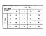
9は基準電圧記憶部であり、平均残存容量算出部7からの平均残存容量SOCavと温度検出部3からの温度サンプルT(n)とに対応した基準電圧値Vstが予め格納されている。基準電圧記憶部9は、図5に示すように、例えばメモリからなる参照テーブル(LUT)として構成される。なお、図5には、特定の温度および残存容量に対する基準電圧値Vstしか記載していないが、特定の温度間および特定の残存容量間に対応する基準電圧値Vstは、例えば補間等により求められる。
【0035】
10は比較部であり、平均電圧算出部8からの平均電圧値Vavと基準電圧記憶部9からの基準電圧値Vstとを比較して、その比較結果を充電効率設定部11に出力する。
【0036】
充電効率設定部11は、図4に示すように、残存容量演算部5で演算しているSOC(n)と温度サンプルT(n)とに対応した初期充電効率η0を格納している記憶部111を有する。充電効率設定部11は、所定の時間期間において比較部10から出力される平均電圧値Vavと基準電圧値Vstとの差分に、所定の補正係数kを乗じて、初期充電効率η0からの増分または減分とし、次の時間期間における充電効率η=η0+k(Vst−Vav)を残存容量演算部5に対して設定する。この充電効率ηに基づいて、残存容量演算部5は、電流サンプルI(n)・充電効率ηの電流積算により、残存容量SOC(n)を演算する。なお、図4には、特定の温度および残存容量に対する初期充電効率η0しか記載していないが、特定の温度間および特定の残存容量間に対応する初期充電効率η0は、例えば補間等により求められる。
【0037】
次に、このように構成された本実施形態における制御プロセスについて、図3を参照して説明する。
【0038】
図3は、本実施形態による残存容量制御ルーチンを示すフローチャートである。
【0039】
図3において、まず、電池電圧V(n)、電流I(n)、および温度T(n)を所定のサンプリング時間毎に取得する(S200)。これら取得した電池電圧V(n)、電流サンプルI(n)、および温度サンプルT(n)に基づいて、主に電流サンプルI(n)・充電効率ηの電流積算により、電池パック1の残存容量SOC(n)を演算する(S201)。ここで、初期状態におけるSOC演算時には、電流検出部2からの充放電方向C/Dに基づき、充電電流については、充電効率ηとして図4の参照テーブルにおける初期充電効率η0を用いる。
【0040】
次に、所定の時間期間、例えば3分間における電池電圧V(n)の平均値Vavを算出する(S202)。また、同じ所定の時間期間、例えば3分間における残存容量(n)の平均値SOCavも算出する(S203)。
【0041】
ステップS203で残存容量の平均値SOCavを算出した後、この残存容量の平均値SOCavと電池温度T(n)に基づき、図5の参照テーブルを用いて、基準電圧値Vstを参照により求める(S204)。
【0042】
次に、ステップS202で算出した平均電圧値VavとステップS204で求めた基準電圧値Vstとを比較し(S205)、その差分に応じて、次の3分間における充電効率ηをη=η0+k(Vst−Vav)として設定する(S206)。その後は、ステップS200、S201に戻って、設定した充電効率ηを用いて電流積算により残存容量SOC(n)を演算し、それ以降のステップが繰り返される。
【0043】
次に、以上のような平均電圧値Vavと基準電圧値Vstとの差分に基づいて充電効率の補正を行なってSOC演算を行なう本実施形態と、かかる充電効率の補正を行なわない場合とにおいて、実際の残容量に対する演算によるSOCの精度について、図7を用いて説明する。
【0044】
図7は、本実施形態による充電効率の補正がある場合とない場合の演算SOCと実際のSOCとの誤差を示す図である。なお、図7は、100時間にわたって連続充放電した後の状態を示している。
【0045】
図7から分かるように、電圧による充電効率の補正を行なわなかった場合には、図4の初期充電効率η0の真値との誤差や電流センサの誤差により積算されたSOCと実際の残容量との間に大きな誤差(21%)が生じた。これに対して、3分毎に積算時に使用する充電効率ηを、3分間における電池電圧の平均値Vavと、その間のSOCの平均値SOCavに基づいて決定される基準電圧値Vstとの差分に応じて補正した場合には、演算されたSOCと実際の残容量は良く一致していた(誤差が3%)。
【0046】
以上のように、本実施形態によれば、積算時に使用する充電効率の値と電池の実際の充電効率の値との誤差や、電流センサの誤差により生じる積算誤差を、容易に修正することができる。
【0047】
なお、本実施形態では、充電効率の補正方法について、η=η0+k(Vst−Vav)と設定したが、平均電圧値と基準電圧値との差分値に応じた値を所定の充電効率から減算したり、所定の充電効率に乗算しても同様の効果が得られる。また、初期充電効率に対して、一定値を加算または減算または乗算したり、別の参照テーブルを用いる補正方法でも同様の効果が得られる。
【0048】
【発明の効果】
以上説明したように、本発明によれば、従来のように電池の電圧変化が大きくなる低SOC領域および高SOC領域でのみSOC補正を行なうのではなく、所定時間毎に検出電圧と基準電圧とを比較し、その比較結果に基づいてSOC演算時の充電効率を可変することで、演算により認識しているSOCと実際のSOCが常に一致する方向に制御されるので、システムのエネルギー管理の精度を大幅に向上させることが可能になる、という格別な効果を奏する。
【図面の簡単な説明】
【図1】 本発明の一実施形態による二次電池の残存容量制御装置の構成を示すブロック図
【図2】 図1の電池入出力制御部6による充電過多パターンを示す波形図(a)および放電過多パターンを示す波形図(b)
【図3】 本発明の一実施形態による残存容量制御ルーチンを示すフローチャート
【図4】 図1の充電効率記憶部111における初期充電効率テーブルを示す図
【図5】 図1の基準電圧記憶部9における基準電圧テーブルを示す図
【図6】 ある温度での実際のSOCと基準電圧値Vstとの関係を示す図
【図7】 本実施形態による充電効率の補正がある場合とない場合の演算SOCと実際のSOCとの誤差を示す図
【符号の説明】
1 電池パック
2 電流検出部
3 温度検出部
4 電圧検出部
5 残存容量演算部
6 電池入出力制御部
7 平均残存容量算出部
8 平均電圧算出部
9 基準電圧記憶部
10 比較部
11 充電効率設定部
111 記憶部
12 モータ
13 エンジン[0001]
BACKGROUND OF THE INVENTION
The present invention relates to a technique for controlling the remaining capacity of a secondary battery such as a nickel-hydrogen secondary battery mounted on an electric vehicle (PEV), a hybrid vehicle (HEV), or the like to perform system energy management with high accuracy. .
[0002]
[Prior art]
Secondary batteries include lead batteries, nickel-cadmium (Ni-Cd) batteries, nickel-hydrogen (Ni-MH) batteries, lithium ion batteries, and the like. These batteries have the property that when power is consumed, they can be charged by connecting to an external power source and flowing a predetermined current. Utilizing this property, these batteries have been used in various devices conventionally.
[0003]
For example, the battery is mounted on a vehicle and serves as an engine starting battery that supplies power to an engine spark plug at the time of starting. Recently, a Ni-MH battery has been used as a main power source for driving a motor in an electric vehicle (PEV) or a so-called hybrid vehicle (HEV) including an engine and a motor.
[0004]
In HEV, when the output from the engine is larger than the power required for traveling, the generator is driven with surplus power to charge the secondary battery. Conversely, when the output from the engine is small, the motor is driven using the power of the secondary battery to output insufficient power. In this case, the secondary battery is discharged. Controlling such charge / discharge and the like to maintain an appropriate operating state is required when a secondary battery is mounted on a hybrid vehicle or the like.
[0005]
For this purpose, the battery voltage, current, temperature, etc. are detected, the remaining capacity (SOC) of the battery is estimated by calculation, and SOC control is performed so that the fuel consumption efficiency of the vehicle is maximized. In addition, the SOC level at that time is generally set within a range of, for example, SOC from 50% to 70% in order to operate the power assist by the motor drive during acceleration and the energy recovery (regenerative braking) during deceleration in a balanced manner. As shown, when the SOC decreases to, for example, 50%, excessive charge control is performed. Conversely, when the SOC increases to, for example, 70%, excessive discharge control is performed. The attempt was made to bring the SOC closer to the control center.
[0006]
In particular, in a secondary battery in which the voltage change is small with respect to the change in SOC and the positive electrode includes nickel oxide as an active material, the SOC is mainly calculated by integrating the charge / discharge current of the battery, and the voltage change is large. In the low SOC region and the high SOC region, the SOC correction by voltage is generally performed.
[0007]
[Problems to be solved by the invention]
However, the SOC correction by the voltage in the low SOC region and the high SOC region is easily influenced by the memory effect, and a sudden change in the SOC recognition value occurs at the time of correction, which is not preferable for the energy management of the system.
[0008]
The present invention has been made in view of such problems, and an object thereof is to provide a secondary battery remaining capacity control method and apparatus in which the accuracy of energy management of the system is greatly improved.
[0009]
[Means for Solving the Problems]
In order to achieve the above object, a secondary battery remaining capacity control method according to the present invention provides a nickel-hydrogen secondary battery for a hybrid vehicle using an intermediate SOC region between a low SOC region and a high SOC region. a remaining capacity control method, the output voltage of the secondary battery, current, and detects the temperature at every predetermined sampling time, by integrating multiplied by a predetermined charge efficiency current it detects, based on the current integrated the remaining capacity is calculated, and calculates an average voltage value of said detected output voltage in the period Jo Tokoro, calculates the average value of the remaining capacity that is calculated on the predetermined period, based on the current integration of the calculated corresponding to the average value and said detected temperature of the remaining capacity, with reference to pre-stored reference voltage value as a reference table of the memory, the ratio between the average voltage value with a reference voltage value obtained by the reference And, based on the result of said comparison, characterized by variably setting the predetermined charge efficiency in the next predetermined period.
[0011]
In the above method according to the present invention, as a result of comparison, when the average voltage value is higher than the reference voltage value, the predetermined charging efficiency is increased, and when the average voltage value is lower than the reference voltage value, the predetermined charging efficiency is increased. When the average voltage value is equal to the reference voltage value, the predetermined charging efficiency is not changed.
[0012]
In this case, the increase or decrease in the predetermined charging efficiency is performed by adding a constant value or a value corresponding to a difference value between the average voltage value and the reference voltage value to the predetermined charging efficiency or from the predetermined charging efficiency. It is preferable to carry out by subtracting or multiplying the predetermined charging efficiency.
[0013]
In the method according to the present invention, the predetermined charge efficiency is preferably determined based on the remaining capacity that the temperature and the current operation it detects.
[0015]
In order to achieve the above object, a first remaining capacity control device for a secondary battery according to the present invention is a nickel-hydrogen secondary battery for a hybrid vehicle that uses an intermediate SOC region between a low SOC region and a high SOC region. A secondary battery remaining capacity control device for detecting a current flowing through a secondary battery at a predetermined sampling time, and multiplying a current signal from the current detection unit by a predetermined charging efficiency and integrating the current signal. A remaining capacity calculation unit that calculates a remaining capacity based on current integration, a temperature detection unit that detects a temperature in the secondary battery at each sampling time, and an output voltage of the secondary battery is detected at each sampling time. The voltage detector, the average voltage calculator for calculating the average voltage value of the voltage signal output from the voltage detector in a predetermined period, and the remaining capacity calculator in the predetermined period. Have been the average remaining capacity calculating unit that calculates an average value of the remaining capacity, the average residual capacity average of the remaining capacity based on current integration from calculator and a reference voltage value corresponding to the temperature detected by said temperature detecting portion A reference voltage storage unit that stores the reference voltage as a reference table in advance, a comparison unit that compares an average voltage value from the average voltage calculation unit with a reference voltage value from the reference voltage storage unit, and the comparison unit And a charging efficiency setting unit that variably sets the predetermined charging efficiency in the next predetermined period with respect to the remaining capacity calculating unit.
[0016]
In order to achieve the above object, a second remaining capacity control device for a secondary battery according to the present invention is a nickel-hydrogen secondary battery for a hybrid vehicle that uses an intermediate SOC region between a low SOC region and a high SOC region. A secondary battery remaining capacity control device comprising a plurality of single cells as secondary batteries, and a battery pack used in an intermediate charge state, and a current flowing through the battery pack at a predetermined sampling time. A current detection unit that detects current, a remaining capacity calculation unit that calculates a remaining capacity based on current integration by multiplying a current signal from the current detection unit by a predetermined charging efficiency, and a temperature in the secondary battery a temperature detection section for detecting for each of the sampling time, a voltage detection unit for detecting an output voltage of the battery pack for each of the sampling time, in a predetermined time period, from the voltage detecting section An average voltage calculation unit that calculates an average voltage value of the applied voltage signal, an average remaining capacity calculation unit that calculates an average value of the remaining capacity calculated by the remaining capacity calculation unit in a predetermined period, and the average remaining value A reference voltage storage unit that stores in advance a reference voltage value corresponding to the temperature detected by the temperature detection unit and the average value of the remaining capacity based on the current integration from the capacity calculation unit, and the average A comparison unit that compares an average voltage value from the voltage calculation unit and a reference voltage value from the reference voltage storage unit, and a predetermined period for the remaining capacity calculation unit based on a comparison result in the comparison unit And a charging efficiency setting unit for variably setting the predetermined charging efficiency.
[0018]
Further, in the first and second remaining capacity control devices, when the average voltage value is higher than the reference voltage value as a result of the comparison in the comparison unit, the charging efficiency setting unit increases the predetermined charging efficiency, and the average voltage value is When the voltage is lower than the reference voltage value, the charging efficiency setting unit decreases the predetermined charging efficiency. When the average voltage value is equal to the reference voltage value, the charging efficiency setting unit does not change the predetermined charging efficiency.
[0019]
In this case, the charging efficiency setting unit adds a constant value or a value corresponding to a difference value between the average voltage value and the reference voltage value to the predetermined charging efficiency, or subtracts from the predetermined charging efficiency, or Preferably, the predetermined charging efficiency is increased or decreased by multiplying the predetermined charging efficiency.
[0020]
First and second remaining capacity control device for a secondary battery, stores charging efficiency setting unit is a charging efficiency corresponding to the current remaining capacity value from the temperature signal and the remaining capacity calculation unit from the temperature detecting portion It is preferable to provide a charging efficiency storage unit.
[0022]
According to the above method and configuration, when it is determined that the SOC recognized by the calculation (recognized SOC) is higher than the actual SOC (actual SOC), the charging efficiency is subtracted, so that during the subsequent integration Since the recognition SOC is lower than the previous integration, it approaches the actual SOC. On the other hand, when it is determined that the recognized SOC is lower than the actual SOC, the charging efficiency is added, so that the recognized SOC rises from the previous accumulated value at the time of the subsequent integration. . Accordingly, by continuing this control, the recognized SOC and the actual SOC are always managed in the same direction, so that the accuracy of energy management of the system can be greatly improved.
[0023]
DETAILED DESCRIPTION OF THE INVENTION
DESCRIPTION OF EXEMPLARY EMBODIMENTS Hereinafter, preferred embodiments of the invention will be described with reference to the drawings.
[0024]
FIG. 1 is a block diagram showing a configuration of a secondary battery remaining capacity control apparatus according to an embodiment of the present invention.
[0025]
In FIG. 1,
[0026]
[0027]
[0028]
A
[0029]
The current sample I (n) and the charge / discharge direction C / D from the
[0030]
A battery input /
[0031]
Further, the battery input /
[0032]
[0033]
An
[0034]
Reference
[0035]
A
[0036]
As shown in FIG. 4, the charging
[0037]
Next, the control process in the present embodiment configured as described above will be described with reference to FIG.
[0038]
FIG. 3 is a flowchart showing a remaining capacity control routine according to the present embodiment.
[0039]
In FIG. 3, first, battery voltage V (n), current I (n), and temperature T (n) are acquired at predetermined sampling times (S200). Based on the acquired battery voltage V (n), current sample I (n), and temperature sample T (n), the remaining
[0040]
Next, an average value Vav of the battery voltage V (n) in a predetermined time period, for example, 3 minutes is calculated (S202). Further, the average value SOCav of the remaining capacity (n) in the same predetermined time period, for example, 3 minutes is calculated (S203).
[0041]
After calculating the average value SOCav of the remaining capacity in step S203, the reference voltage value Vst is obtained by reference using the reference table of FIG. 5 based on the average value SOCav of the remaining capacity and the battery temperature T (n) (S204). ).
[0042]
Next, the average voltage value Vav calculated in step S202 is compared with the reference voltage value Vst obtained in step S204 (S205), and the charging efficiency η for the next three minutes is set to η = η 0 + k according to the difference. It is set as (Vst−Vav) (S206). Thereafter, the process returns to steps S200 and S201, the remaining capacity SOC (n) is calculated by current integration using the set charging efficiency η, and the subsequent steps are repeated.
[0043]
Next, in the present embodiment in which the SOC calculation is performed by correcting the charging efficiency based on the difference between the average voltage value Vav and the reference voltage value Vst as described above, and when the charging efficiency is not corrected, The accuracy of the SOC obtained by calculating the actual remaining capacity will be described with reference to FIG.
[0044]
FIG. 7 is a diagram illustrating an error between the calculated SOC and the actual SOC with and without the charging efficiency correction according to the present embodiment. In addition, FIG. 7 has shown the state after charging / discharging continuously over 100 hours.
[0045]
As can be seen from FIG. 7, when the charging efficiency is not corrected by the voltage, the SOC and the actual remaining capacity integrated by the error from the true value of the initial charging efficiency η 0 in FIG. A large error (21%) occurred between On the other hand, the charging efficiency η used for integration every 3 minutes is the difference between the average value Vav of the battery voltage in 3 minutes and the reference voltage value Vst determined based on the average value SOCav of the SOC therebetween. When corrected accordingly, the calculated SOC and the actual remaining capacity were in good agreement (the error was 3%).
[0046]
As described above, according to the present embodiment, it is possible to easily correct the error between the charging efficiency value used during integration and the actual charging efficiency value of the battery, and the integration error caused by the current sensor error. it can.
[0047]
In this embodiment, the charging efficiency correction method is set as η = η 0 + k (Vst−Vav). However, a value corresponding to the difference value between the average voltage value and the reference voltage value is determined from the predetermined charging efficiency. The same effect can be obtained by subtracting or multiplying a predetermined charging efficiency. The same effect can be obtained by a correction method that adds, subtracts, or multiplies a constant value to the initial charging efficiency or uses another reference table.
[0048]
【The invention's effect】
As described above, according to the present invention, the SOC correction is not performed only in the low SOC region and the high SOC region where the voltage change of the battery is large as in the prior art, but the detection voltage and the reference voltage are set every predetermined time. And the charging efficiency at the time of SOC calculation is varied based on the comparison result, so that the SOC recognized by the calculation and the actual SOC are always controlled to coincide with each other. There is an extraordinary effect that can be greatly improved.
[Brief description of the drawings]
FIG. 1 is a block diagram showing the configuration of a secondary battery remaining capacity control device according to an embodiment of the present invention. FIG. 2 is a waveform diagram (a) showing an overcharge pattern by a battery input /
3 is a flowchart showing a remaining capacity control routine according to an embodiment of the present invention. FIG. 4 is a diagram showing an initial charge efficiency table in the charge
DESCRIPTION OF
Claims (11)
二次電池の出力電圧、電流、及び温度を所定のサンプリング時間毎に検出し、
検出した電流に所定の充電効率を乗じて積算することにより、電流積算に基づく残存容量を演算し、
所定の期間に検出された前記出力電圧の平均電圧値を算出し、
前記所定の期間に演算された残存容量の平均値を算出し、
前記算出された電流積算に基づく残存容量の平均値及び検出された前記温度に対応する、メモリーからなる参照テーブルとして予め格納された基準電圧値を参照し、
前記参照により求めた基準電圧値と前記平均電圧値とを比較し、
前記比較した結果に基づいて、次の所定の期間における前記所定の充電効率を可変設定することを特徴とする二次電池の残存容量制御方法。A method for controlling a remaining capacity of a nickel-hydrogen secondary battery for a hybrid vehicle using an intermediate SOC region between a low SOC region and a high SOC region,
The output voltage, current, and temperature of the secondary battery are detected every predetermined sampling time,
By integrating multiplied by a predetermined charge efficiency test out current, it calculates the remaining capacity based on current integration,
Calculates an average voltage value of said detected output voltage to a predetermined period of constant,
Calculating an average value of the remaining capacity calculated during the predetermined period;
With reference to the reference voltage value stored in advance as a reference table consisting of a memory , corresponding to the average value of the remaining capacity based on the calculated current integration and the detected temperature ,
Compare the reference voltage value obtained by the reference and the average voltage value,
A method for controlling a remaining capacity of a secondary battery, wherein the predetermined charging efficiency in a next predetermined period is variably set based on the comparison result.
二次電池に流れる電流を所定のサンプリング時間毎に検出する電流検出部と、
前記電流検出部からの電流信号に所定の充電効率を乗じて積算することにより、電流積算に基づく残存容量を演算する残存容量演算部と、
二次電池内の温度を前記サンプリング時間毎に検出する温度検出部と、
二次電池の出力電圧を前記サンプリング時間毎に検出する電圧検出部と、
所定の期間において、前記電圧検出部から出力された電圧信号の平均電圧値を算出する平均電圧算出部と、
所定の期間において、前記残存容量演算部で演算された残存容量の平均値を算出する平均残存容量算出部と、
前記平均残存容量算出部からの電流積算に基づく残存容量の平均値及び前記温度検出部により検出された温度に対応する基準電圧値をメモリーからなる参照テーブルとして予め格納している基準電圧記憶部と、
前記平均電圧算出部からの平均電圧値と前記基準電圧記憶部からの基準電圧値とを比較する比較部と、
前記比較部における比較結果に基づいて、前記残存容量演算部に対して次の所定の期間における前記所定の充電効率を可変設定する充電効率設定部とを備えたことを特徴とする二次電池の残存容量制御装置。A remaining capacity control device for a nickel-hydrogen secondary battery for a hybrid vehicle using an intermediate SOC region between a low SOC region and a high SOC region,
A current detector that detects the current flowing through the secondary battery every predetermined sampling time ;
A remaining capacity calculation unit that calculates a remaining capacity based on the current integration by multiplying the current signal from the current detection unit by a predetermined charging efficiency and integrating the current signal;
A temperature detector for detecting the temperature in the secondary battery every sampling time;
A voltage detector that detects the output voltage of the secondary battery every sampling time ;
An average voltage calculator that calculates an average voltage value of the voltage signal output from the voltage detector in a predetermined period;
An average remaining capacity calculation unit that calculates an average value of the remaining capacity calculated by the remaining capacity calculation unit in a predetermined period;
A reference voltage storage unit preliminarily storing a reference voltage value corresponding to the average value of the remaining capacity based on current accumulation from the average remaining capacity calculation unit and the temperature detected by the temperature detection unit as a reference table including a memory; ,
A comparison unit that compares an average voltage value from the average voltage calculation unit and a reference voltage value from the reference voltage storage unit;
A secondary battery comprising: a charge efficiency setting unit configured to variably set the predetermined charge efficiency in a next predetermined period for the remaining capacity calculation unit based on a comparison result in the comparison unit Residual capacity control device.
二次電池である複数個の単電池を組み合わせて成り、中間的充電状態で使用される電池パックと、
前記電池パックに流れる電流を所定のサンプリング時間毎に検出する電流検出部と、
前記電流検出部からの電流信号に所定の充電効率を乗じて積算することにより、電流積算に基づく残存容量を演算する残存容量演算部と、
二次電池内の温度を前記サンプリング時間毎に検出する温度検出部と、
前記電池パックの出力電圧を前記サンプリング時間毎に検出する電圧検出部と、
所定の期間において、前記電圧検出部から出力された電圧信号の平均電圧値を算出する平均電圧算出部と、
所定の期間において、前記残存容量演算部で演算された残存容量の平均値を算出する平均残存容量算出部と、
前記平均残存容量算出部からの電流積算に基づく残存容量の平均値及び前記温度検出部により検出された温度に対応する基準電圧値をメモリーからなる参照テーブルとして予め格納している基準電圧記憶部と、
前記平均電圧算出部からの平均電圧値と前記基準電圧記憶部からの基準電圧値とを比較する比較部と、
前記比較部における比較結果に基づいて、前記残存容量演算部に対して次の所定の期間における前記所定の充電効率を可変設定する充電効率設定部とを備えたことを特徴とする二次電池の残存容量制御装置。A remaining capacity control device for a nickel-hydrogen secondary battery for a hybrid vehicle using an intermediate SOC region between a low SOC region and a high SOC region,
A battery pack composed of a combination of a plurality of single cells as secondary batteries and used in an intermediate charge state;
A current detector that detects the current flowing through the battery pack every predetermined sampling time ;
A remaining capacity calculation unit that calculates a remaining capacity based on the current integration by multiplying the current signal from the current detection unit by a predetermined charging efficiency and integrating the current signal;
A temperature detector for detecting the temperature in the secondary battery every sampling time;
A voltage detector for detecting the output voltage of the battery pack every sampling time ;
An average voltage calculator that calculates an average voltage value of the voltage signal output from the voltage detector in a predetermined period;
An average remaining capacity calculation unit that calculates an average value of the remaining capacity calculated by the remaining capacity calculation unit in a predetermined period;
A reference voltage storage unit preliminarily storing a reference voltage value corresponding to the average value of the remaining capacity based on the current accumulation from the average remaining capacity calculation unit and the temperature detected by the temperature detection unit as a reference table including a memory; ,
A comparison unit that compares an average voltage value from the average voltage calculation unit and a reference voltage value from the reference voltage storage unit;
A secondary battery comprising: a charge efficiency setting unit configured to variably set the predetermined charge efficiency in a next predetermined period for the remaining capacity calculation unit based on a comparison result in the comparison unit Residual capacity control device.
Priority Applications (4)
| Application Number | Priority Date | Filing Date | Title |
|---|---|---|---|
| JP2001173030A JP4523738B2 (en) | 2001-06-07 | 2001-06-07 | Secondary battery remaining capacity control method and apparatus |
| US10/163,807 US6646421B2 (en) | 2001-06-07 | 2002-06-05 | Method and apparatus for controlling residual battery capacity of secondary battery |
| DE60228522T DE60228522D1 (en) | 2001-06-07 | 2002-06-06 | Method and apparatus for battery residual capacity monitoring for secondary battery |
| EP02012621A EP1265335B1 (en) | 2001-06-07 | 2002-06-06 | Method and apparatus for controlling residual battery capacity of secondary battery |
Applications Claiming Priority (1)
| Application Number | Priority Date | Filing Date | Title |
|---|---|---|---|
| JP2001173030A JP4523738B2 (en) | 2001-06-07 | 2001-06-07 | Secondary battery remaining capacity control method and apparatus |
Publications (2)
| Publication Number | Publication Date |
|---|---|
| JP2002369391A JP2002369391A (en) | 2002-12-20 |
| JP4523738B2 true JP4523738B2 (en) | 2010-08-11 |
Family
ID=19014555
Family Applications (1)
| Application Number | Title | Priority Date | Filing Date |
|---|---|---|---|
| JP2001173030A Expired - Fee Related JP4523738B2 (en) | 2001-06-07 | 2001-06-07 | Secondary battery remaining capacity control method and apparatus |
Country Status (4)
| Country | Link |
|---|---|
| US (1) | US6646421B2 (en) |
| EP (1) | EP1265335B1 (en) |
| JP (1) | JP4523738B2 (en) |
| DE (1) | DE60228522D1 (en) |
Families Citing this family (67)
| Publication number | Priority date | Publication date | Assignee | Title |
|---|---|---|---|---|
| US7005830B2 (en) * | 2002-06-17 | 2006-02-28 | Enerdel, Inc. | Rechargeable battery pack with adaptive regenerative energy control and method thereof |
| JP3863092B2 (en) * | 2002-11-20 | 2006-12-27 | 本田技研工業株式会社 | In-vehicle motor regeneration control device |
| JP2004184135A (en) * | 2002-11-29 | 2004-07-02 | Sanyo Electric Co Ltd | Remaining-capacity calculating system of battery |
| JP3933096B2 (en) * | 2003-06-03 | 2007-06-20 | トヨタ自動車株式会社 | Battery control device and control method mounted on vehicle |
| US7321220B2 (en) * | 2003-11-20 | 2008-01-22 | Lg Chem, Ltd. | Method for calculating power capability of battery packs using advanced cell model predictive techniques |
| US7233128B2 (en) * | 2004-07-30 | 2007-06-19 | Ford Global Technologies, Llc | Calculation of state of charge offset using a closed integral method |
| JP4843921B2 (en) * | 2004-09-02 | 2011-12-21 | 日産自動車株式会社 | Battery pack capacity adjustment device and battery pack capacity adjustment method |
| US8103485B2 (en) * | 2004-11-11 | 2012-01-24 | Lg Chem, Ltd. | State and parameter estimation for an electrochemical cell |
| US7723957B2 (en) * | 2005-11-30 | 2010-05-25 | Lg Chem, Ltd. | System, method, and article of manufacture for determining an estimated battery parameter vector |
| JP4967362B2 (en) * | 2006-02-09 | 2012-07-04 | トヨタ自動車株式会社 | Secondary battery remaining capacity estimation device |
| JP2007240182A (en) * | 2006-03-06 | 2007-09-20 | Sony Corp | Battery pack and its residual capacity information providing device |
| US7663342B2 (en) * | 2007-01-26 | 2010-02-16 | Solarbridge Technologies, Inc. | Apparatus, system, and method for controlling multiple power supplies |
| JP5009721B2 (en) * | 2007-08-24 | 2012-08-22 | プライムアースEvエナジー株式会社 | Secondary battery charge state estimation device and program |
| US8346419B2 (en) * | 2007-09-26 | 2013-01-01 | Tesla Motors, Inc. | Operation of a range extended electric vehicle |
| US7755916B2 (en) | 2007-10-11 | 2010-07-13 | Solarbridge Technologies, Inc. | Methods for minimizing double-frequency ripple power in single-phase power conditioners |
| US7994755B2 (en) | 2008-01-30 | 2011-08-09 | Lg Chem, Ltd. | System, method, and article of manufacture for determining an estimated battery cell module state |
| EP2279425B1 (en) * | 2008-05-07 | 2011-09-07 | Commissariat à l'Énergie Atomique et aux Énergies Alternatives | Method of estimation of the state of charge of a battery |
| US8279642B2 (en) | 2009-07-31 | 2012-10-02 | Solarbridge Technologies, Inc. | Apparatus for converting direct current to alternating current using an active filter to reduce double-frequency ripple power of bus waveform |
| WO2011013248A1 (en) * | 2009-07-31 | 2011-02-03 | 富士通株式会社 | Method for indicating remaining capacity, program for indicating remaining capacity, device for indicating remaining capacity, and electronic device |
| US8462518B2 (en) | 2009-10-12 | 2013-06-11 | Solarbridge Technologies, Inc. | Power inverter docking system for photovoltaic modules |
| TWI394972B (en) * | 2009-11-25 | 2013-05-01 | Htc Corp | Method and system for estimating battery percentage |
| US8824178B1 (en) | 2009-12-31 | 2014-09-02 | Solarbridge Technologies, Inc. | Parallel power converter topology |
| KR101356899B1 (en) * | 2010-02-24 | 2014-01-28 | 미츠비시 쥬고교 가부시키가이샤 | Charging-rate computation system |
| US8924057B2 (en) * | 2010-03-19 | 2014-12-30 | GM Global Technology Operations LLC | Method for starting a hybrid vehicle |
| US8341449B2 (en) | 2010-04-16 | 2012-12-25 | Lg Chem, Ltd. | Battery management system and method for transferring data within the battery management system |
| WO2011148214A1 (en) * | 2010-05-27 | 2011-12-01 | Nokia Corporation | Method of evaluating remaining power of a battery for portable devices |
| US8704496B2 (en) | 2010-06-11 | 2014-04-22 | Toyota Jidosha Kabushiki Kaisha | Charge control system |
| US8503200B2 (en) | 2010-10-11 | 2013-08-06 | Solarbridge Technologies, Inc. | Quadrature-corrected feedforward control apparatus and method for DC-AC power conversion |
| US8279649B2 (en) | 2010-10-11 | 2012-10-02 | Solarbridge Technologies, Inc. | Apparatus and method for controlling a power inverter |
| US9160408B2 (en) | 2010-10-11 | 2015-10-13 | Sunpower Corporation | System and method for establishing communication with an array of inverters |
| US9467063B2 (en) | 2010-11-29 | 2016-10-11 | Sunpower Corporation | Technologies for interleaved control of an inverter array |
| US8842454B2 (en) | 2010-11-29 | 2014-09-23 | Solarbridge Technologies, Inc. | Inverter array with localized inverter control |
| AT510802A1 (en) * | 2010-12-07 | 2012-06-15 | Felix Dipl Ing Dr Himmelstoss | BATTERY CHARGING SYSTEM FOR NON-CONSTANT SOURCES |
| JP5741153B2 (en) * | 2011-04-06 | 2015-07-01 | トヨタ自動車株式会社 | Charge control device |
| US8449998B2 (en) | 2011-04-25 | 2013-05-28 | Lg Chem, Ltd. | Battery system and method for increasing an operational life of a battery cell |
| US8611107B2 (en) | 2011-04-27 | 2013-12-17 | Solarbridge Technologies, Inc. | Method and system for controlling a multi-stage power inverter |
| US9065354B2 (en) | 2011-04-27 | 2015-06-23 | Sunpower Corporation | Multi-stage power inverter for power bus communication |
| US8193788B2 (en) | 2011-04-27 | 2012-06-05 | Solarbridge Technologies, Inc. | Method and device for controlling a configurable power supply to provide AC and/or DC power output |
| US8859119B2 (en) | 2011-06-30 | 2014-10-14 | Lg Chem, Ltd. | Heating system for a battery module and method of heating the battery module |
| US8974928B2 (en) | 2011-06-30 | 2015-03-10 | Lg Chem, Ltd. | Heating system for a battery module and method of heating the battery module |
| US8974929B2 (en) | 2011-06-30 | 2015-03-10 | Lg Chem, Ltd. | Heating system for a battery module and method of heating the battery module |
| US8993136B2 (en) | 2011-06-30 | 2015-03-31 | Lg Chem, Ltd. | Heating system for a battery module and method of heating the battery module |
| US8922185B2 (en) | 2011-07-11 | 2014-12-30 | Solarbridge Technologies, Inc. | Device and method for global maximum power point tracking |
| US8284574B2 (en) | 2011-10-17 | 2012-10-09 | Solarbridge Technologies, Inc. | Method and apparatus for controlling an inverter using pulse mode control |
| US8766597B2 (en) * | 2011-10-21 | 2014-07-01 | Linear Technology Corporation | Optimized bi-directional balancing method and system |
| KR101863036B1 (en) * | 2011-11-30 | 2018-06-01 | 주식회사 실리콘웍스 | Method for estimating the state of charge of battery and battery management system |
| US9276635B2 (en) | 2012-06-29 | 2016-03-01 | Sunpower Corporation | Device, system, and method for communicating with a power inverter using power line communications |
| AT513335B1 (en) | 2012-09-13 | 2017-10-15 | Fronius Int Gmbh | Method and device for charging batteries |
| DE102012224417A1 (en) * | 2012-12-27 | 2014-07-17 | Robert Bosch Gmbh | Method for determining a state of charge |
| US9952288B2 (en) | 2013-02-05 | 2018-04-24 | Hitachi Automotive Systems, Ltd. | Battery controller |
| US10031185B2 (en) | 2013-02-13 | 2018-07-24 | Exide Technologies | Method for determining a state of charge and remaining operation life of a battery |
| US10664562B2 (en) * | 2013-02-24 | 2020-05-26 | Fairchild Semiconductor Corporation and University of Connecticut | Battery state of charge tracking, equivalent circuit selection and benchmarking |
| US9584044B2 (en) | 2013-03-15 | 2017-02-28 | Sunpower Corporation | Technologies for converter topologies |
| US9564835B2 (en) | 2013-03-15 | 2017-02-07 | Sunpower Corporation | Inverter communications using output signal |
| FR3009389B1 (en) * | 2013-08-02 | 2017-02-10 | Commissariat Energie Atomique | ENERGY MANAGEMENT IN A BATTERY |
| US10250861B2 (en) * | 2013-11-22 | 2019-04-02 | North Inc. | Methods and devices for detecting open and/or shorts circuits in MEMS micro-mirror devices |
| US20170210596A1 (en) * | 2014-01-27 | 2017-07-27 | Otis Elevator Company | Charge algorithm for battery propelled elevator |
| JP6220904B2 (en) * | 2016-01-14 | 2017-10-25 | 本田技研工業株式会社 | Power storage device |
| JP6500795B2 (en) * | 2016-02-01 | 2019-04-17 | トヨタ自動車株式会社 | Vehicle battery SOC management system |
| JP6851734B2 (en) * | 2016-06-27 | 2021-03-31 | ダイハツ工業株式会社 | Charge amount calculation device |
| JP6790931B2 (en) * | 2017-03-14 | 2020-11-25 | 株式会社デンソー | Battery state estimator |
| US10921381B2 (en) * | 2017-07-28 | 2021-02-16 | Northstar Battery Company, Llc | Systems and methods for monitoring and presenting battery information |
| US11018512B2 (en) | 2018-12-06 | 2021-05-25 | Hitachi Automotive Systems Americas, Inc. | Energy storage device charge balancing |
| JP7151570B2 (en) * | 2019-03-15 | 2022-10-12 | 株式会社デンソー | power controller |
| KR20210031336A (en) * | 2019-09-11 | 2021-03-19 | 주식회사 엘지화학 | Apparatus and method for diagnosing battery |
| CN113611902B (en) * | 2021-07-09 | 2023-01-06 | 东风柳州汽车有限公司 | Method and device for calculating total residual energy of hydrogen fuel cell vehicle |
| CN116094016B (en) * | 2023-04-11 | 2023-06-27 | 深圳市德兰明海新能源股份有限公司 | Energy storage equipment alternating current multiphase system and electric quantity balance control method thereof |
Family Cites Families (7)
| Publication number | Priority date | Publication date | Assignee | Title |
|---|---|---|---|---|
| GB1437025A (en) * | 1972-08-30 | 1976-05-26 | Deutsche Automobilgesellsch | Method and device for determining the state of charge of galvanic energy sources |
| JP3178315B2 (en) | 1994-11-21 | 2001-06-18 | セイコーエプソン株式会社 | Battery remaining capacity meter and remaining capacity calculation method |
| TW300957B (en) | 1994-11-21 | 1997-03-21 | Seiko Epson Corp | |
| FR2740877B1 (en) * | 1995-11-06 | 1998-01-09 | Renault | METHOD FOR DETERMINING THE CHARGING STATE OF A BATTERY |
| WO1998002933A1 (en) * | 1996-07-17 | 1998-01-22 | Duracell Inc. | Battery operating system |
| US6025695A (en) * | 1997-07-09 | 2000-02-15 | Friel; Daniel D. | Battery operating system |
| JP3864590B2 (en) | 1998-11-25 | 2007-01-10 | トヨタ自動車株式会社 | Battery charge state detection device |
-
2001
- 2001-06-07 JP JP2001173030A patent/JP4523738B2/en not_active Expired - Fee Related
-
2002
- 2002-06-05 US US10/163,807 patent/US6646421B2/en not_active Expired - Fee Related
- 2002-06-06 EP EP02012621A patent/EP1265335B1/en not_active Expired - Lifetime
- 2002-06-06 DE DE60228522T patent/DE60228522D1/en not_active Expired - Lifetime
Also Published As
| Publication number | Publication date |
|---|---|
| EP1265335A2 (en) | 2002-12-11 |
| US20020196026A1 (en) | 2002-12-26 |
| US6646421B2 (en) | 2003-11-11 |
| EP1265335A3 (en) | 2006-08-16 |
| EP1265335B1 (en) | 2008-08-27 |
| DE60228522D1 (en) | 2008-10-09 |
| JP2002369391A (en) | 2002-12-20 |
Similar Documents
| Publication | Publication Date | Title |
|---|---|---|
| JP4523738B2 (en) | Secondary battery remaining capacity control method and apparatus | |
| JP3964635B2 (en) | Memory effect detection method and solution | |
| EP1460709B1 (en) | Method and device for estimating remaining capacity of secondary cell, battery pack system, and electric vehicle | |
| US6356083B1 (en) | State of charge algorithm for a battery | |
| EP3664247B1 (en) | Charging time computation method and charge control device | |
| US9649950B2 (en) | Power supply apparatus | |
| JP4308408B2 (en) | Secondary battery input / output controller | |
| JP3870577B2 (en) | Variation determination method for battery pack and battery device | |
| US8674659B2 (en) | Charge control device and vehicle equipped with the same | |
| US6359419B1 (en) | Quasi-adaptive method for determining a battery's state of charge | |
| CN108819731B (en) | Charge rate estimation method and vehicle-mounted battery system | |
| US6608482B2 (en) | Battery control method for hybrid vehicle | |
| JP5379672B2 (en) | Secondary battery polarization voltage calculation device and charging state estimation device | |
| JP5009223B2 (en) | Secondary battery remaining capacity estimation method and apparatus | |
| US20120161709A1 (en) | Secondary-battery control apparatus | |
| JP3808367B2 (en) | Secondary battery output control device and method, and battery pack system | |
| JP2000134805A (en) | Battery assembly charge/discharge state deciding method and battery assembly charge/discharge state deciding device | |
| JP2001086604A (en) | Set-battery and remaining capacity detector | |
| JP4121098B2 (en) | Rechargeable battery residual capacity detection method using nickel hydroxide positive electrode | |
| JP2001314041A (en) | Charging/discharging control apparatus and method | |
| JP2001186682A (en) | Method of controlling discharge of battery | |
| CN115864559A (en) | Method for charging battery | |
| JP2003339124A (en) | Power supply unit for vehicle | |
| JP3628912B2 (en) | Battery charge state detection device | |
| JP2002027681A (en) | Method of recharging battery set including plural electric cells |
Legal Events
| Date | Code | Title | Description |
|---|---|---|---|
| A621 | Written request for application examination |
Free format text: JAPANESE INTERMEDIATE CODE: A621 Effective date: 20050208 |
|
| A977 | Report on retrieval |
Free format text: JAPANESE INTERMEDIATE CODE: A971007 Effective date: 20060914 |
|
| A131 | Notification of reasons for refusal |
Free format text: JAPANESE INTERMEDIATE CODE: A131 Effective date: 20061026 |
|
| A521 | Request for written amendment filed |
Free format text: JAPANESE INTERMEDIATE CODE: A523 Effective date: 20061221 |
|
| A02 | Decision of refusal |
Free format text: JAPANESE INTERMEDIATE CODE: A02 Effective date: 20070508 |
|
| A521 | Request for written amendment filed |
Free format text: JAPANESE INTERMEDIATE CODE: A523 Effective date: 20070709 |
|
| A521 | Request for written amendment filed |
Free format text: JAPANESE INTERMEDIATE CODE: A523 Effective date: 20070713 |
|
| A911 | Transfer to examiner for re-examination before appeal (zenchi) |
Free format text: JAPANESE INTERMEDIATE CODE: A911 Effective date: 20070815 |
|
| A912 | Re-examination (zenchi) completed and case transferred to appeal board |
Free format text: JAPANESE INTERMEDIATE CODE: A912 Effective date: 20071026 |
|
| A521 | Request for written amendment filed |
Free format text: JAPANESE INTERMEDIATE CODE: A523 Effective date: 20090804 |
|
| A01 | Written decision to grant a patent or to grant a registration (utility model) |
Free format text: JAPANESE INTERMEDIATE CODE: A01 |
|
| A61 | First payment of annual fees (during grant procedure) |
Free format text: JAPANESE INTERMEDIATE CODE: A61 Effective date: 20100528 |
|
| R150 | Certificate of patent or registration of utility model |
Free format text: JAPANESE INTERMEDIATE CODE: R150 Ref document number: 4523738 Country of ref document: JP Free format text: JAPANESE INTERMEDIATE CODE: R150 |
|
| FPAY | Renewal fee payment (event date is renewal date of database) |
Free format text: PAYMENT UNTIL: 20130604 Year of fee payment: 3 |
|
| FPAY | Renewal fee payment (event date is renewal date of database) |
Free format text: PAYMENT UNTIL: 20130604 Year of fee payment: 3 |
|
| R250 | Receipt of annual fees |
Free format text: JAPANESE INTERMEDIATE CODE: R250 |
|
| R250 | Receipt of annual fees |
Free format text: JAPANESE INTERMEDIATE CODE: R250 |
|
| R250 | Receipt of annual fees |
Free format text: JAPANESE INTERMEDIATE CODE: R250 |
|
| R250 | Receipt of annual fees |
Free format text: JAPANESE INTERMEDIATE CODE: R250 |
|
| R250 | Receipt of annual fees |
Free format text: JAPANESE INTERMEDIATE CODE: R250 |
|
| R250 | Receipt of annual fees |
Free format text: JAPANESE INTERMEDIATE CODE: R250 |
|
| R250 | Receipt of annual fees |
Free format text: JAPANESE INTERMEDIATE CODE: R250 |
|
| R250 | Receipt of annual fees |
Free format text: JAPANESE INTERMEDIATE CODE: R250 |
|
| LAPS | Cancellation because of no payment of annual fees |