JP4320743B2 - Rotating machine control device - Google Patents
Rotating machine control device Download PDFInfo
- Publication number
- JP4320743B2 JP4320743B2 JP2007053232A JP2007053232A JP4320743B2 JP 4320743 B2 JP4320743 B2 JP 4320743B2 JP 2007053232 A JP2007053232 A JP 2007053232A JP 2007053232 A JP2007053232 A JP 2007053232A JP 4320743 B2 JP4320743 B2 JP 4320743B2
- Authority
- JP
- Japan
- Prior art keywords
- current
- value
- control
- timing
- rotating machine
- Prior art date
- Legal status (The legal status is an assumption and is not a legal conclusion. Google has not performed a legal analysis and makes no representation as to the accuracy of the status listed.)
- Active
Links
Images


Classifications
-
- H—ELECTRICITY
- H02—GENERATION; CONVERSION OR DISTRIBUTION OF ELECTRIC POWER
- H02P—CONTROL OR REGULATION OF ELECTRIC MOTORS, ELECTRIC GENERATORS OR DYNAMO-ELECTRIC CONVERTERS; CONTROLLING TRANSFORMERS, REACTORS OR CHOKE COILS
- H02P27/00—Arrangements or methods for the control of AC motors characterised by the kind of supply voltage
- H02P27/04—Arrangements or methods for the control of AC motors characterised by the kind of supply voltage using variable-frequency supply voltage, e.g. inverter or converter supply voltage
- H02P27/06—Arrangements or methods for the control of AC motors characterised by the kind of supply voltage using variable-frequency supply voltage, e.g. inverter or converter supply voltage using dc to ac converters or inverters
-
- H—ELECTRICITY
- H02—GENERATION; CONVERSION OR DISTRIBUTION OF ELECTRIC POWER
- H02P—CONTROL OR REGULATION OF ELECTRIC MOTORS, ELECTRIC GENERATORS OR DYNAMO-ELECTRIC CONVERTERS; CONTROLLING TRANSFORMERS, REACTORS OR CHOKE COILS
- H02P23/00—Arrangements or methods for the control of AC motors characterised by a control method other than vector control
- H02P23/0004—Control strategies in general, e.g. linear type, e.g. P, PI, PID, using robust control
- H02P23/0027—Control strategies in general, e.g. linear type, e.g. P, PI, PID, using robust control using different modes of control depending on a parameter, e.g. the speed
-
- H—ELECTRICITY
- H02—GENERATION; CONVERSION OR DISTRIBUTION OF ELECTRIC POWER
- H02P—CONTROL OR REGULATION OF ELECTRIC MOTORS, ELECTRIC GENERATORS OR DYNAMO-ELECTRIC CONVERTERS; CONTROLLING TRANSFORMERS, REACTORS OR CHOKE COILS
- H02P27/00—Arrangements or methods for the control of AC motors characterised by the kind of supply voltage
- H02P27/04—Arrangements or methods for the control of AC motors characterised by the kind of supply voltage using variable-frequency supply voltage, e.g. inverter or converter supply voltage
- H02P27/06—Arrangements or methods for the control of AC motors characterised by the kind of supply voltage using variable-frequency supply voltage, e.g. inverter or converter supply voltage using dc to ac converters or inverters
- H02P27/08—Arrangements or methods for the control of AC motors characterised by the kind of supply voltage using variable-frequency supply voltage, e.g. inverter or converter supply voltage using dc to ac converters or inverters with pulse width modulation
- H02P27/10—Arrangements or methods for the control of AC motors characterised by the kind of supply voltage using variable-frequency supply voltage, e.g. inverter or converter supply voltage using dc to ac converters or inverters with pulse width modulation using bang-bang controllers
-
- H—ELECTRICITY
- H02—GENERATION; CONVERSION OR DISTRIBUTION OF ELECTRIC POWER
- H02P—CONTROL OR REGULATION OF ELECTRIC MOTORS, ELECTRIC GENERATORS OR DYNAMO-ELECTRIC CONVERTERS; CONTROLLING TRANSFORMERS, REACTORS OR CHOKE COILS
- H02P29/00—Arrangements for regulating or controlling electric motors, appropriate for both AC and DC motors
- H02P29/02—Providing protection against overload without automatic interruption of supply
- H02P29/024—Detecting a fault condition, e.g. short circuit, locked rotor, open circuit or loss of load
- H02P29/027—Detecting a fault condition, e.g. short circuit, locked rotor, open circuit or loss of load the fault being an over-current
Landscapes
- Engineering & Computer Science (AREA)
- Power Engineering (AREA)
- Control Of Motors That Do Not Use Commutators (AREA)
- Inverter Devices (AREA)
- Control Of Ac Motors In General (AREA)
Description
本発明は、回転機に電力を供給するインバータのスイッチング素子を操作することで該回転機の回転に関する物理量を制御する回転機の制御装置に関する。 The present invention relates to a control device for a rotating machine that controls a physical quantity related to the rotation of the rotating machine by operating a switching element of an inverter that supplies electric power to the rotating machine.
例えば下記特許文献1に見られるように、3相回転機に対する指令電流によって定まる所定のヒステリシス領域の上限及び下限と実電流との大小に基づきインバータのスイッチング素子を操作することで、実電流を、要求トルクを生成するための要求電流にフィードバック制御する瞬時電流値制御を行う制御装置が周知である。
For example, as seen in the following
また、回転機の出力トルクや回転速度が大きい領域においては、回転機の電気角の1周期内にオン状態及びオフ状態が1度ずつとなるようにスイッチング素子を操作するいわゆる矩形波制御を行う制御装置も周知である。矩形波制御によれば、高出力、高回転領域において電力損失の増大を抑制することができるのみならず、インバータの入力電圧に対する相間電圧の1次成分の実効値によって定義される電圧利用率を向上させることもできる。 Also, in a region where the output torque and the rotation speed of the rotating machine are large, so-called rectangular wave control is performed in which the switching element is operated so that the on state and the off state become 1 degree each within one cycle of the electrical angle of the rotating machine. Control devices are also well known. According to the rectangular wave control, not only can an increase in power loss be suppressed in a high output and high rotation range, but also a voltage utilization factor defined by an effective value of a primary component of an interphase voltage with respect to an input voltage of an inverter. It can also be improved.
なお、上記以外にも、下記特許文献2に見られる制御装置もある。
ただし、上記瞬時電流値制御では、高回転速度に移行するにつれて、実電流が指令電流からずれ、ひいては、要求トルクを生成することが困難となるおそれがある。すなわち、通常運転時には、インバータの入力電圧が3相回転機の逆起電力よりも大きいために、実電流の変化速度が指令電流の変化速度よりも十分大きい。このため、実電流がヒステリシス領域内で小刻みに変化しつつも指令電流への追従が可能となる。これに対し、高回転速度領域では、3相回転機を流れる実電流と指令電流との位相ずれが顕著となる。これは、高回転速度領域ではインバータの入力電圧と3相回転機の逆起電力との差が小さくなるために、3相回転機を流れる実電流の変化速度が指令電流の変化速度と同程度となるためである。 However, in the instantaneous current value control, the actual current may deviate from the command current as it shifts to a higher rotational speed, and it may be difficult to generate the required torque. That is, during normal operation, since the input voltage of the inverter is larger than the back electromotive force of the three-phase rotating machine, the actual current changing speed is sufficiently larger than the command current changing speed. For this reason, it is possible to follow the command current while the actual current changes little by little in the hysteresis region. On the other hand, in the high rotation speed region, the phase shift between the actual current flowing through the three-phase rotating machine and the command current becomes significant. This is because, in the high rotation speed region, the difference between the input voltage of the inverter and the back electromotive force of the three-phase rotating machine is small, so the change rate of the actual current flowing through the three-phase rotating machine is about the same as the change rate of the command current It is because it becomes.
そして、指令電流と実電流との間に位相ずれが生じると、要求トルクに対して実際に3相回転機が出力するトルクがずれたものとなる。 When a phase shift occurs between the command current and the actual current, the torque actually output from the three-phase rotating machine is shifted from the required torque.
これに対し、矩形波制御では、高回転速度、高出力トルク領域において回転機の出力トルクを要求トルクに適切に制御することができる。ただし、矩形波制御では、回転機を流れる電流がオープン制御されることとなるため、電流が過度に大きくなる等の可能性を否定できない。そして回転機に過度に大きい電流が流れると、インバータのスイッチング素子の信頼性を低下させる等の不都合が生じることとなる。 On the other hand, in the rectangular wave control, the output torque of the rotating machine can be appropriately controlled to the required torque in a high rotation speed and high output torque region. However, in the rectangular wave control, since the current flowing through the rotating machine is open-controlled, the possibility that the current becomes excessively large cannot be denied. When an excessively large current flows through the rotating machine, problems such as a decrease in the reliability of the switching element of the inverter occur.
本発明は、上記課題を解決するためになされたものであり、その目的は、回転機の出力トルクを要求トルクにより適切に制御することのできる回転機の制御装置を提供することにある。 The present invention has been made to solve the above-described problems, and an object of the present invention is to provide a control device for a rotating machine that can appropriately control the output torque of the rotating machine based on the required torque.
以下、上記課題を解決するための手段、及びその作用効果について記載する。 Hereinafter, means for solving the above-described problems and the operation and effects thereof will be described.
請求項1記載の発明は、前記回転機の電気角の1回転周期内にオン状態及びオフ状態が1度ずつとなるように前記スイッチング素子を操作することで、前記回転機の出力トルクを要求トルクに制御する矩形波制御手段と、前記回転機に対する指令電流よりも大きい値を上限値として且つ前記指令電流よりも小さい値を下限値とするヒステリシス領域内に実電流を制御すべく、前記ヒステリシス領域の上限及び下限と前記実電流との大小関係に基づき前記インバータのスイッチング素子を操作する瞬時電流値制御手段と、前記矩形波制御手段による制御がなされているときに前記回転機を流れる電流が前記ヒステリシス領域から外れる場合、前記瞬時電流値制御手段による制御に切り替える切替手段とを備えることを特徴とする。 According to the first aspect of the present invention, the output torque of the rotating machine is requested by operating the switching element so that the ON state and the OFF state become 1 degree each within one rotation cycle of the electrical angle of the rotating machine. A rectangular wave control means for controlling torque, and the hysteresis to control an actual current in a hysteresis region having a value larger than a command current for the rotating machine as an upper limit and a value smaller than the command current as a lower limit. The instantaneous current value control means for operating the switching element of the inverter based on the magnitude relationship between the upper and lower limits of the region and the actual current, and the current flowing through the rotating machine when controlled by the rectangular wave control means And switching means for switching to the control by the instantaneous current value control means when it is out of the hysteresis region.
上記発明では、矩形波制御手段による制御を行うことで、インバータの入力電圧に対する相電圧の1次成分の実効値で定義される電圧利用率を理論上最大とすることができる。このため、高回転速度領域や、高出力トルク領域においても、回転機の出力トルクを、要求トルクに好適に制御することができる。ただし、矩形波制御手段による制御では、回転機を流れる実電流をフィードバック制御することができない。このため、例えば回転速度が急激に低下することで回転機の誘起電圧が急減する際には、実電流が過度に多くなる等の問題を生じる。この点、上記発明では、切替手段を備えることで、回転機の実電流を適切にフィードバック制御することができるため、実電流の制御性の低下を好適に回避することができる。 In the above invention, the voltage utilization rate defined by the effective value of the primary component of the phase voltage with respect to the input voltage of the inverter can be theoretically maximized by performing the control by the rectangular wave control means. For this reason, the output torque of the rotating machine can be suitably controlled to the required torque even in the high rotation speed region and the high output torque region. However, the control by the rectangular wave control means cannot feedback control the actual current flowing through the rotating machine. For this reason, for example, when the induced voltage of the rotating machine rapidly decreases due to a rapid decrease in the rotational speed, there arises a problem that the actual current is excessively increased. In this regard, in the above-described invention, since the switching unit is provided, the actual current of the rotating machine can be appropriately feedback controlled, so that a decrease in the controllability of the actual current can be suitably avoided.
請求項2記載の発明は、請求項1記載の発明において、前記矩形波制御手段は、前記瞬時電流値制御手段の前記指令電流を、前記要求トルクを生成するための要求電流と同周期且つ該要求電流よりも振幅の大きい大振幅指令電流とする手段と、前記大振幅指令電流の値が前記要求電流の値と交わるタイミングを予測する交点予測手段と、該交わるタイミングにおいて前記瞬時電流値制御手段による前記スイッチング素子の操作状態の切り替えが未だなされていないときに前記操作状態を強制的に切り替える強制手段とを備えることを特徴とする。 According to a second aspect of the present invention, in the first aspect of the invention, the rectangular wave control unit has the same period of the command current of the instantaneous current value control unit as the required current for generating the required torque, and Means for setting a large amplitude command current having a larger amplitude than the requested current; intersection prediction means for predicting the timing at which the value of the large amplitude command current intersects the value of the requested current; and the instantaneous current value control means at the timing of the intersection And a forcing means for forcibly switching the operation state when the operation state of the switching element is not yet switched.
指令電流を、要求電流と同周期且つ要求電流よりも大きな振幅として瞬時電流値制御を行うと、指令電流の振幅が大きいために、指令電流と実電流が交差するタイミング近傍において、実電流が上記ヒステリシス領域をはみ出す。このため、指令電流と実電流が交差するタイミング近傍において、スイッチング素子の操作状態が切り替わることとなる。このため、瞬時電流値制御手段による制御によって、回転機の電気角の1回転周期内にオン状態及びオフ状態が1度ずつとなるようにスイッチング素子を操作することができる。しかも、大振幅指令電流の位相を適合することで、大振幅指令電流と実電流とが交わる際の位相を調節することができ、ひいてはスイッチングの切り替えの位相を調節することができる。これにより、回転機の実電流を要求電流に適切にフィードバック制御することができる。 When instantaneous current value control is performed with the command current in the same cycle as the request current and with an amplitude larger than the request current, since the amplitude of the command current is large, the actual current is near the timing at which the command current and the actual current intersect. It protrudes from the hysteresis area. For this reason, the operation state of the switching element is switched near the timing at which the command current and the actual current intersect. For this reason, by the control by the instantaneous current value control means, the switching element can be operated so that the on state and the off state become 1 degree each within one rotation cycle of the electrical angle of the rotating machine. In addition, by adapting the phase of the large amplitude command current, it is possible to adjust the phase when the large amplitude command current and the actual current intersect, and thus to adjust the switching phase of switching. As a result, the actual current of the rotating machine can be appropriately feedback controlled to the required current.
ただし、この場合、実電流がヒステリシス領域をはみ出してから瞬時電流値制御手段による次の制御タイミングまでの間は、瞬時電流値制御手段によってはスイッチング素子の操作状態が切り替えられることはない。このため、大振幅指令電流を用いた瞬時電流値制御手段によるスイッチング素子の操作状態の切り替えタイミングは、矩形波制御によって要求トルクを生成するための切り替えタイミングに対して遅延するおそれがある。この点、上記発明では、大振幅指令電流と要求電流とが交わるタイミングにおいてスイッチング素子の操作状態を切り替えることで、瞬時電流値制御手段に矩形波制御の一端を担わせつつも、これによっては矩形波制御を適切に行うことができないときにこれを補償することができる。 However, in this case, the operation state of the switching element is not switched by the instantaneous current value control means until the actual current protrudes from the hysteresis region until the next control timing by the instantaneous current value control means. For this reason, the switching timing of the operation state of the switching element by the instantaneous current value control means using the large amplitude command current may be delayed with respect to the switching timing for generating the required torque by the rectangular wave control. In this regard, in the above-described invention, by switching the operation state of the switching element at the timing at which the large amplitude command current and the required current cross, the instantaneous current value control means is responsible for one end of the rectangular wave control, This can be compensated when the wave control cannot be performed properly.
請求項3記載の発明は、回転機の実電流を要求トルクを生成するための要求電流にフィードバック制御すべく、前記回転機に対する指令電流よりも大きい値を上限値として且つ前記指令電流よりも小さい値を下限値とする所定のヒステリシス領域の上限及び下限と前記実電流との大小関係に基づきインバータのスイッチング素子を操作する瞬時電流値制御手段と、前記指令電流を、前記要求電流と同周期且つ前記要求電流よりも大きい振幅を有する大振幅指令電流に設定する設定手段と、前記大振幅指令電流が前記要求電流と交わるタイミングを予測する交点予測手段と、該交わるタイミングにおいて前記瞬時電流値制御手段によって前記スイッチング素子の操作状態が未だ切り替えられていないときに前記操作状態を強制的に切り替える強制手段とを備えることを特徴とする。 According to a third aspect of the invention, in order to feedback control the required current for generating the required torque actual current times turning point, smaller than and the command current value greater than the command current to the rotating machine as an upper limit value Instantaneous current value control means for operating the switching element of the inverter based on the magnitude relationship between the upper limit and lower limit of a predetermined hysteresis region whose value is the lower limit value and the actual current, and the command current is in the same cycle as the required current and Setting means for setting a large-amplitude command current having an amplitude larger than the required current, intersection prediction means for predicting a timing at which the large-amplitude command current intersects the requested current, and the instantaneous current value control means at the intersection timing The operation state of the switching element is forcibly switched when the operation state of the switching element has not been switched yet. Characterized in that it comprises a means.
指令電流を、要求電流と同周期且つ要求電流よりも大きな振幅として瞬時電流値制御を行うと、指令電流の振幅が大きいために、指令電流と実電流が交差するタイミング近傍において、実電流が上記ヒステリシス領域をはみ出す。このため、指令電流と実電流が交差するタイミング近傍において、スイッチング素子の操作状態が切り替わることとなる。このため、回転機の電気角の1回転周期内にオン状態及びオフ状態が1度ずつとなるようにスイッチング素子を操作することができる。しかも、大振幅指令電流の位相を適合することで、スイッチングの切り替えの位相を調節することができ、ひいては、回転機の実電流を要求電流に適切にフィードバック制御することができる。 When instantaneous current value control is performed with the command current in the same cycle as the request current and with an amplitude larger than the request current, since the amplitude of the command current is large, the actual current is near the timing at which the command current and the actual current intersect. It protrudes from the hysteresis area. For this reason, the operation state of the switching element is switched near the timing at which the command current and the actual current intersect. For this reason, a switching element can be operated so that an ON state and an OFF state may become 1 degree | times within one rotation period of the electrical angle of a rotary machine. Moreover, by adapting the phase of the large-amplitude command current, the switching switching phase can be adjusted, and as a result, the actual current of the rotating machine can be appropriately feedback-controlled to the required current.
ただし、この場合、実電流がヒステリシス領域をはみ出してから瞬時電流値制御手段による次の制御タイミングまでの間は、瞬時電流値制御手段によってはスイッチング素子の操作状態が切り替えられることはない。このため、大振幅指令電流を用いた瞬時電流値制御手段によるスイッチング素子の操作状態の切り替えタイミングは、矩形波制御によって要求トルクを生成するための切り替えタイミングに対して遅延するおそれがある。この点、上記発明では、強制手段を備えることで、こうした問題を回避することができる。 However, in this case, the operation state of the switching element is not switched by the instantaneous current value control means until the actual current protrudes from the hysteresis region until the next control timing by the instantaneous current value control means. For this reason, the switching timing of the operation state of the switching element by the instantaneous current value control means using the large amplitude command current may be delayed with respect to the switching timing for generating the required torque by the rectangular wave control. In this regard, in the above invention, such a problem can be avoided by providing the forcing means.
請求項4記載の発明は、請求項2又は3記載の発明において、前記強制手段による切り替えがなされた時点から予め定められた期間、前記瞬時電流値制御手段による前記スイッチング素子の操作状態の切り替えを禁止する禁止手段を更に備えることを特徴とする。 According to a fourth aspect of the present invention, in the invention according to the second or third aspect, the operation state of the switching element is switched by the instantaneous current value control unit for a predetermined period from the time when the switching by the forcing unit is performed. It further comprises a prohibiting means for prohibiting.
強制手段によるスイッチング素子の操作状態の切り替えがなされた直後においては、瞬時電流値制御手段によるスイッチング素子の操作指令が強制手段による操作指令と相違すると考えられる。このため、強制手段による切り替え直後から瞬時電流値制御手段によるスイッチング素子の操作を許可する場合には、要求トルクを生成するために適切な位相でスイッチング素子が切り替えられているにもかかわらず、これが妨げられるおそれがある。この点、上記発明では、禁止手段を備えることで、こうした問題を回避することができる。 Immediately after the operation state of the switching element is switched by the forcing means, it is considered that the operation command for the switching element by the instantaneous current value control means is different from the operation command by the forcing means. For this reason, when the operation of the switching element by the instantaneous current value control means is permitted immediately after switching by the forcing means, this is done even though the switching element is switched at an appropriate phase to generate the required torque. May be disturbed. In this regard, in the above invention, such a problem can be avoided by providing the prohibiting means.
なお、禁止手段によって切り替えを禁止する所定期間は、回転機の回転に伴う電気角の半回転(指令電流の半周期)よりも短い期間とすることが望ましい。特に所定期間は、瞬時電流値制御手段によるスイッチング素子の操作指令と強制手段による操作指令とが一致するまでに要すると想定される期間以上であって且つ極力短い期間とすることが望ましい。 Incidentally, between the periodic place you prohibit switching the inhibiting means, it is desirable that the period shorter than the (half period of the command current) half turn of an electrical angle according to the rotation of the rotating machine. In particular, the predetermined period is preferably a period that is longer than a period that is assumed to be required until the operation command of the switching element by the instantaneous current value control unit and the operation command of the forcing unit coincide with each other and is as short as possible.
請求項5記載の発明は、請求項2〜4のいずれかに記載の発明において、前記交点予測手段は、前記瞬時電流値制御の次回の制御タイミングにおける前記大振幅指令電流の値及び前記要求電流の値を予測する電流値予測手段と、前記大振幅指令電流及び前記要求電流についての今回の制御タイミングの値及び前記予測される次回の制御タイミングの値の大小関係の変化に基づき前記次回の制御タイミングまでに前記交わるタイミングが生じるか否かを判断する判断手段と、前記交わるタイミングが生じると判断されるとき、前記交わるタイミングまでの所要時間を算出する所要時間算出手段とを備えることを特徴とする。 According to a fifth aspect of the present invention, in the invention according to any one of the second to fourth aspects, the intersection predicting means includes the value of the large amplitude command current and the required current at the next control timing of the instantaneous current value control. Current value predicting means for predicting the value of the current control, and the next control based on a change in the magnitude relationship between the current control timing value and the predicted next control timing value for the large amplitude command current and the required current. A determination means for determining whether or not the intersection timing occurs before the timing; and a required time calculation means for calculating a required time until the intersection timing when the intersection timing is determined to occur. To do.
今回の制御タイミングから次回の制御タイミングまでの期間において大振幅指令電流が要求電流と交わる場合、大振幅指令電流と要求電流との大小関係は、今回の制御タイミングと次回の制御タイミングとで逆転すると考えられる。上記判断手段は、この点に着目し、交わるタイミングが生じるか否かを適切に判断することができる。そして交わるタイミングが生じるとの判断がなされるときに所要時間を算出することで、所要時間を適切に算出することもできる。 If the large amplitude command current intersects with the required current during the period from the current control timing to the next control timing, the magnitude relationship between the large amplitude command current and the required current is reversed between the current control timing and the next control timing. Conceivable. The determination means pays attention to this point and can appropriately determine whether or not the timing of crossing occurs. The required time can be calculated appropriately by calculating the required time when it is determined that the timing of crossing will occur.
請求項6記載の発明は、請求項5記載の発明において、前記強制手段は、更に、前記大振幅指令電流及び前記要求電流の大小関係が前回の制御タイミングと今回の制御タイミングとで互いに相違して且つ、前記前回の制御タイミングから前記今回の制御タイミングまでに前記スイッチング素子の操作状態が切り替えられていないとき、前記操作状態を強制的に切り替えることを特徴とする。 According to a sixth aspect of the present invention, in the fifth aspect of the present invention, the forcing means is further configured so that the magnitude relationship between the large amplitude command current and the required current is different between the previous control timing and the current control timing. In addition, when the operation state of the switching element is not switched from the previous control timing to the current control timing, the operation state is forcibly switched.
上記電流値予測手段による予測に誤差が生じると、今回の制御タイミングから次回の制御タイミングまでの間に大振幅指令電流と要求電流とが交わるタイミングがあるにもかかわらず、判断手段によって交わるタイミングがないと誤判断されるおそれがある。この場合には、瞬時電流値制御によってスイッチング素子の操作状態の切り替えがなされない限り、スイッチング素子の操作状態の切り替えがなされないおそれがある。こうした事態が生じる場合、次回の制御タイミングとなるときには、大振幅指令電流と要求電流との大小関係が逆転している。上記発明では、この点に着目し、上記電流値予測手段の予測誤差に起因するスイッチング素子の操作状態の切り替えに遅延が生じることを上記大小関係の逆転に基づき判断し、遅延が生じているときには直ちにスイッチング素子の操作状態を切り替えることで、遅延時間を極力低減することができる。 If an error occurs in the prediction by the current value predicting means, there is a timing at which the large amplitude command current and the requested current intersect between the current control timing and the next control timing, but the timing at which the judgment means intersects. Otherwise, it may be misjudged. In this case, the operation state of the switching element may not be switched unless the operation state of the switching element is switched by the instantaneous current value control. When such a situation occurs, the magnitude relationship between the large amplitude command current and the required current is reversed at the next control timing. In the above invention, paying attention to this point, it is determined based on the reversal of the magnitude relationship that there is a delay in switching the operation state of the switching element due to the prediction error of the current value predicting means. The delay time can be reduced as much as possible by immediately switching the operation state of the switching element.
請求項7記載の発明は、請求項1記載の発明において、前記瞬時電流値制御手段は、前記要求トルクを生成するための要求電流を指令電流とするものであって且つ、前記ヒステリシス領域の上限よりも前記実電流の方が大きいとき、前記ヒステリシス領域内に前記実電流が包含されているとき、及び前記ヒステリシス領域の下限よりも前記実電流が小さいときのそれぞれで各別の論理値を出力する出力手段を備え、前記切替手段は、前記出力手段の論理値に基づき前記切り替えを行うことを特徴とする。 According to a seventh aspect of the present invention, in the first aspect of the invention, the instantaneous current value control means uses a required current for generating the required torque as a command current, and the upper limit of the hysteresis region. the gas and the larger actual current than when the actual current is included in said hysteresis region, and each different logical values at each time the actual current is smaller than the lower limit of the hysteresis region An output means for outputting is provided, wherein the switching means performs the switching based on a logical value of the output means.
上記発明では、矩形波制御手段による制御がなされつつも、要求電流に応じて定まるヒステリシス領域から実電流が外れるときには、出力手段の論理値に基づきこれを把握することができる。このため、こうした状況下には瞬時電流値制御を行うことができるため、矩形波制御を行いつつも、実電流を要求電流に適切にフィードバック制御することができる。 In the above invention, when the actual current deviates from the hysteresis region determined according to the required current while being controlled by the rectangular wave control means, this can be grasped based on the logical value of the output means. For this reason, since instantaneous current value control can be performed under such circumstances, the actual current can be appropriately feedback-controlled to the required current while performing rectangular wave control.
請求項8記載の発明は、請求項7記載の発明において、前記ヒステリシス領域を、前記回転機の回転速度及び前記回転機のトルクに応じて可変設定することを特徴とする。
The invention according to claim 8 is the invention according to
ヒステリシス領域の上限及び下限間の幅(ヒステリシス幅)を狭くするほど、実電流が要求電流からずれるずれ量を小さくすることができる。ただし、ヒステリシス幅を過度に小さくすると矩形波制御が正常になされているにもかかわらず実電流がヒステリシス領域からはみ出す。そして、この場合には、矩形波制御が妨げられ、電圧利用率が低下する。ここで、矩形波制御が正常になされているときの実電流と要求電流とのずれ量の最大値は、回転速度や要求トルクに応じて変化する。この点、上記発明では、回転速度やトルクに応じてヒステリシス領域(ヒステリシス幅)を可変設定することで、矩形波制御が正常になされているときにこれが妨げられることを回避しつつも、実電流を要求電流に極力追従させることができる。 As the width between the upper limit and the lower limit of the hysteresis region (hysteresis width) is narrowed, the amount of deviation of the actual current from the required current can be reduced. However, when the hysteresis width is excessively reduced, the actual current protrudes from the hysteresis region even though the rectangular wave control is normally performed. In this case, the rectangular wave control is hindered and the voltage utilization rate is reduced. Here, the maximum value of the deviation amount between the actual current and the required current when the rectangular wave control is normally performed changes according to the rotation speed and the required torque. In this respect, in the above-described invention, the hysteresis region (hysteresis width) is variably set according to the rotation speed and torque, so that the obstruction of the rectangular wave control is prevented while the normal current is being prevented. Can follow the required current as much as possible.
請求項9記載の発明は、請求項7又は8記載の発明において、前記ヒステリシス領域は、矩形波制御が正常になされているときにおける前記指令電流及び前記実電流のずれ量が最大値となるときの前記実電流を包含するように設定されてなることを特徴とする。
The invention according to
上記発明では、矩形波制御が正常になされているときにこれが妨げられることを回避することができる。 In the said invention, when rectangular wave control is made normally, it can avoid preventing this.
請求項10記載の発明は、請求項7〜9のいずれかに記載の発明において、前記矩形波制御手段は、前記要求電流と同周期且つ該要求電流よりも振幅の大きい大振幅指令電流が前記要求電流と交わるタイミングを予測する交点予測手段と、該交点予測手段によって予測されるタイミングで前記スイッチング素子の操作状態の切り替えを行う手段とを備えることを特徴とする。 According to a tenth aspect of the present invention, in the invention according to any one of the seventh to ninth aspects, the rectangular wave control means has a large-amplitude command current having the same period as the required current and a larger amplitude than the required current. An intersection prediction unit that predicts a timing of intersecting with the required current, and a unit that switches the operation state of the switching element at a timing predicted by the intersection prediction unit.
上記発明では、大振幅指令電流が要求電流となるタイミングによって、矩形波制御によるスイッチング素子の操作状態の切り替えタイミングを規定することができる。 In the above invention, the switching timing of the operation state of the switching element by the rectangular wave control can be defined by the timing at which the large amplitude command current becomes the required current.
請求項11記載の発明は、請求項10記載の発明において、前記交点予測手段は、前記矩形波制御の次回の制御タイミングにおける前記大振幅指令電流及び前記要求電流を予測する電流値予測手段と、前記大振幅指令電流及び前記要求電流についての今回の制御タイミングの値及び前記予測される次回の制御タイミングの値の大小関係の変化に基づき前記次回の制御タイミングまでの間に前記交わるタイミングが生じるか否かを判断する判断手段と、前記交わるタイミングが生じると判断されるとき、前記交わるタイミングまでの所要時間を算出する所要時間算出手段とを備えることを特徴とする。
The invention according to claim 11 is the invention according to
今回の制御タイミングから次回の制御タイミングまでの期間において大振幅指令電流が要求電流と交わる場合、大振幅指令電流と要求電流との大小関係は、今回の制御タイミングと次回の制御タイミングとで逆転すると考えられる。上記判断手段は、この点に着目し、交わるタイミングが生じるか否かを適切に判断することができる。そして交わるタイミングが生じるとの判断がなされるときに所要時間を算出することで、所要時間を適切に算出することもできる。 If the large amplitude command current intersects with the required current during the period from the current control timing to the next control timing, the magnitude relationship between the large amplitude command current and the required current is reversed between the current control timing and the next control timing. Conceivable. The determination means pays attention to this point and can appropriately determine whether or not the timing of crossing occurs. The required time can be calculated appropriately by calculating the required time when it is determined that the timing of crossing will occur.
請求項12記載の発明は、請求項5,6,11のいずれかに記載の発明において、前記大振幅指令電流及び前記要求電流についての静止座標系での値を設定する手段と、該静止座標系での値を回転座標系での値に変換する変換手段とを更に備え、前記電流値予測手段は、前記静止座標系での値を入力信号とする前記変換手段の出力信号に基づき前記大振幅指令電流及び前記要求電流の時間微分演算を行う手段と、該時間微分演算結果に基づき、前記次回の制御タイミングにおける前記大振幅指令電流及び前記要求電流をテイラー級数によって算出する手段とを備えることを特徴とする。 A twelfth aspect of the invention is the invention according to any one of the fifth, sixth, and eleventh aspects, wherein means for setting values in the stationary coordinate system for the large amplitude command current and the required current, and the stationary coordinates Conversion means for converting a value in the system into a value in the rotating coordinate system, and the current value predicting means is configured to output the large value based on an output signal of the conversion means using a value in the stationary coordinate system as an input signal. and means for performing time differentiation calculation of the amplitude command current and the required current, on the basis of said time differential calculation result, and means for calculating the in the next control timing large amplitude command current and the required current by Taylor series It is characterized by that.
静止座標系での値を回転座標系にて変換することで大振幅指令電流や要求電流を算出する場合、この変換は、通常、三角関数にて定義される。このため、大振幅指令電流や要求電流は微分可能な曲線となり、その所定時間後の値は、テイラー級数によって近似することができる。ここで、大振幅指令電流や要求電流の時間微分演算は、静止座標系でのこれらの値に基づき、上記変換手段を用いて行うことができる。換言すれば、静止座標系での値を回転座標系での値に変換する変換手段の変換処理によって、上記微分演算をするのと等価の演算をすることができる。上記発明では、この点に着目し、所定次数のテイラー級数を簡易に算出することができ、ひいては次回の制御タイミングにおける大振幅指令電流や要求電流を簡易に予測することができる。 When a large amplitude command current or a required current is calculated by converting a value in a stationary coordinate system in a rotating coordinate system, this conversion is usually defined by a trigonometric function. For this reason, the large amplitude command current and the required current are differentiable curves, and the values after the predetermined time can be approximated by a Taylor series. Here, the time differential calculation of the large amplitude command current and the required current can be performed using the conversion means based on these values in the stationary coordinate system. In other words, an operation equivalent to the above-described differential operation can be performed by the conversion process of the conversion means for converting the value in the stationary coordinate system into the value in the rotating coordinate system. In the above invention, focusing on this point, a Taylor series of a predetermined order can be easily calculated, and as a result, a large amplitude command current and a required current at the next control timing can be easily predicted.
なお、請求項12記載の発明は、請求項13記載の発明によるように、前記電流値予測手段は、1次又は2次までのテイラー級数によって前記算出を行うことを特徴としてもよい。 According to a twelfth aspect of the invention, as in the thirteenth aspect of the invention, the current value predicting means may perform the calculation by a Taylor series up to the first order or the second order .
請求項14記載の発明は、請求項5,6,11のいずれかに記載の発明において、前記大振幅指令電流及び前記要求電流についての静止座標系での値を設定する手段と、該静止座標系での値を回転座標系での値に変換する変換手段とを更に備え、前記電流値予測手段は、前記制御タイミング間の時間間隔と前記回転機の現在の電気角速度との乗算値を算出する手段と、前記現在の制御タイミングにおける前記大振幅指令電流及び前記要求電流についての静止座標系での値をそれぞれ、現在の電気角度を前記乗算値だけ進角させた電気角度を用いて前記変換手段により変換することで前記次回の制御タイミングにおける前記大振幅指令電流及び前記要求電流を予測することを特徴とする。 According to a fourteenth aspect of the present invention, in the invention according to any one of the fifth, sixth and eleventh aspects, means for setting values in the stationary coordinate system for the large amplitude command current and the required current, and the stationary coordinates Conversion means for converting a value in the system into a value in the rotating coordinate system, and the current value prediction means calculates a multiplication value of a time interval between the control timings and a current electrical angular velocity of the rotating machine. And converting the values of the large amplitude command current and the required current in the stationary coordinate system at the current control timing using an electrical angle obtained by advancing the current electrical angle by the multiplication value, respectively. The large-amplitude command current and the required current at the next control timing are predicted by conversion by means.
上記発明では、大振幅指令電流及び要求電流の静止座標系での値を回転座標系での値に変換するに際し、変換に用いる電気角を現在の値に対し上記乗算値だけ進角させることで、次回の制御タイミングにおける大振幅指令電流及び要求電流を算出することができる。 In the above invention, when the value of the large amplitude command current and the required current in the stationary coordinate system is converted to the value in the rotating coordinate system, the electrical angle used for the conversion is advanced by the multiplication value with respect to the current value. The large amplitude command current and the required current at the next control timing can be calculated.
なお、請求項5及び6及び11〜14のいずれかに記載の発明は、請求項15記載の発明によるように、前記矩形波制御手段は、前記所要時間算出手段によって所要時間が算出されてからの時刻を計時する計時手段と、該計時手段によって計時される時間が前記所要時間と一致するときに前記切り替えを行う手段とを備えることを特徴としてもよい。
In the invention according to any one of
請求項16記載の発明は、請求項15記載の発明において、前記大振幅指令電流の振幅は、前記計時手段の計時動作の周期Tc、前記大振幅指令電流の最小単位量Ad、前記大振幅指令電流を用いる際の前記回転機の最小電気角速度ωminを用いて、「Ad/(ωmin×Tc)」以上となるように設定されてなることを特徴とする。 According to a sixteenth aspect of the invention, in the fifteenth aspect of the invention, the amplitude of the large amplitude command current includes a period Tc of the time measuring operation of the time measuring means, a minimum unit amount Ad of the large amplitude command current, and the large amplitude command. The minimum electrical angular velocity ωmin of the rotating machine when using current is set to be equal to or higher than “Ad / (ωmin × Tc)”.
制御タイミング間の時間間隔Tと計時動作の周期Tcとによって、時間間隔Tの間の計時動作回数を、「T/Tc」と表すことができる。一方、時間間隔Tの間に、大振幅指令電流が増加する増加回数を、制御装置による大振幅指令電流の表現の最小単位量Adと、電気角速度ωと、大振幅指令電流の変化速度dA2とによって表現すると、「ω×A2×T/Ad」となる。時間間隔T内では要求電流の変化は無視できるとものとすると、大振幅指令電流が要求電流と交わるタイミングの算出精度を計時動作の精度と同程度以上とするためには、「ω×A2×T/Ad≧T/Tc」とする必要がある。これから、「A2≧Ad/(ω×Tc)」が求まる。ここで、右辺はωが小さいほど大きくなる。このため、大振幅指令電流を用いる際の回転機の最小電気角速度ωminを用いると、振幅A2が満たすべき式は、「A2≧Ad/(ωmin×Tc)」となる。 By the time interval T between the control timings and the period Tc of the time measuring operation, the number of times of the time measuring operation during the time interval T can be expressed as “T / Tc”. On the other hand, during the time interval T, the number of increases in which the large amplitude command current increases is expressed as the minimum unit amount Ad of the large amplitude command current expressed by the control device, the electrical angular velocity ω, and the change rate dA2 of the large amplitude command current. Is expressed as “ω × A2 × T / Ad”. Assuming that the change in the required current is negligible within the time interval T, in order to make the calculation accuracy of the timing at which the large amplitude command current intersects the required current be equal to or higher than the accuracy of the timing operation, “ω × A2 × It is necessary to satisfy “T / Ad ≧ T / Tc”. From this, “A2 ≧ Ad / (ω × Tc)” is obtained. Here, the right side becomes larger as ω is smaller. For this reason, when the minimum electrical angular velocity ωmin of the rotating machine when using the large amplitude command current is used, the equation that the amplitude A2 should satisfy is “A2 ≧ Ad / (ωmin × Tc)”.
請求項17記載の発明は、請求項5,6,11〜16記載の発明において、前記所要時間算出手段は、前記大振幅指令電流及び前記要求電流についてのそれぞれの時間微分値の差に対する前記大振幅指令電流及び前記要求電流の差に基づき前記所要時間を算出することを特徴とする。 According to a seventeenth aspect of the present invention, in the inventions of the fifth, sixth, and eleventh to sixteenth aspects, the required time calculation means is configured to calculate the large difference with respect to a difference between time differential values of the large amplitude command current and the required current. The required time is calculated based on a difference between an amplitude command current and the required current.
上記発明では、今回の制御タイミングから次回の制御タイミングまでの短い時間間隔において大振幅指令電流と要求電流とを線形近似することで所要時間を簡易に算出することができる。特に、静止座標系での値を回転座標系での値に変換する変換手段を備えて大振幅指令電流及び要求電流を算出する場合には、変換手段を流用することで時間微分値を簡易に算出可能である。 In the above invention, the required time can be easily calculated by linearly approximating the large amplitude command current and the required current in a short time interval from the current control timing to the next control timing. In particular, when calculating a large-amplitude command current and required current with conversion means for converting a value in a stationary coordinate system into a value in a rotating coordinate system, the time differential value can be easily obtained by diverting the conversion means. It can be calculated.
請求項18記載の発明は、請求項2〜6のいずれかに記載の発明において、前記大振幅指令電流の振幅は、前記インバータの最大定格電流値に2の平方根を乗算した値以下に設定されてなることを特徴とする。
The invention according to
上記発明では、大振幅指令電流の振幅を最大定格電流に2の平方根を乗算した値以下に設定するために、インバータを流れる電流の絶対値が最大定格電流を越えて大きくなるときには、大振幅指令電流によって定まるヒステリシス領域から実電流がはみ出す。このため、上記実電流の絶対値を減少させるようフィードバック制御がなされることとなる。このため、上記発明では、インバータを流れる電流が最大定格電流を越えることを好適に抑制することができる。 In the above invention, since the amplitude of the large amplitude command current is set to be equal to or less than the value obtained by multiplying the maximum rated current by the square root of 2, when the absolute value of the current flowing through the inverter becomes larger than the maximum rated current, the large amplitude command current is set. The actual current protrudes from the hysteresis region determined by the current. For this reason, feedback control is performed so as to reduce the absolute value of the actual current. For this reason, in the said invention, it can suppress suitably that the electric current which flows through an inverter exceeds a maximum rated current.
請求項19記載の発明は、請求項2〜6、10〜18のいずれかに記載の発明において、前記電気角度の1回転周期内にオン状態及びオフ状態が1度ずつとなるように前記スイッチング素子を操作することで前記要求トルクを実現するための前記スイッチング素子の操作状態の切り替えタイミングにおいて、前記大振幅指令電流が前記要求電流と交わるように適合されてなることを特徴とする。 According to a nineteenth aspect of the present invention, in the invention according to any one of the second to sixth and tenth to eighteenth aspects, the switching is performed so that the on state and the off state become one degree within one rotation period of the electrical angle. The large-amplitude command current is adapted to intersect the required current at the switching timing of the operation state of the switching element for realizing the required torque by operating the element.
上記発明では、大振幅指令電流と実電流が交わるタイミング近傍において瞬時電流値制御によりスイッチング素子の操作が切り替えられる。ここで、上記発明では、大振幅指令電流と実電流が交わるタイミングを、要求電流を実現するための矩形波制御によるスイッチング素子の操作状態の切り替えタイミングとすることで、瞬時電流値制御によって、矩形波制御によるスイッチング素子の操作状態の切り替えタイミング近傍において切り替えを行うことができる。 In the above invention, the operation of the switching element is switched by the instantaneous current value control in the vicinity of the timing at which the large amplitude command current and the actual current cross. In the above invention, the timing at which the large-amplitude command current and the actual current cross is set as the switching timing of the operation state of the switching element by the rectangular wave control for realizing the required current. Switching can be performed in the vicinity of the switching timing of the operating state of the switching element by wave control.
請求項20記載の発明は、請求項2〜6、10〜19のいずれかに記載の発明において、前記大振幅指令電流の振幅A2は、前記要求電流の振幅A1よりも大きな値に設定されて且つ、前記大振幅指令電流の位相T2は、前記要求電流の一周期内にオン状態及びオフ状態が1度ずつとなるように前記スイッチング素子を操作することで前記要求トルクを実現するために想定される前記操作状態の切り替え位相T3と前記要求電流の位相T1とによって、
T2=T3−arcsin{(A1/A2)×sin(T3−T1)}
に設定することを特徴とする。
The invention according to
T2 = T3-arcsin {(A1 / A2) × sin (T3-T1)}
It is characterized by setting to.
上記発明において、回転機の電気角速度wを用いると、要求電流は、「A1×sin(wt−T1)」と、また、大振幅指令電流は、「A2×sin(wt−T2)」とそれぞれ表現される。ここで、要求電流と大振幅指令電流とが位相T3において交差すると仮定すると、以下の関係が成立する。 In the above invention, when the electrical angular velocity w of the rotating machine is used, the required current is “A1 × sin (wt−T1)”, and the large amplitude command current is “A2 × sin (wt−T2)”. Expressed. Here, assuming that the required current and the large amplitude command current intersect at the phase T3, the following relationship is established.
A1×sin(T3−T1)=A2×sin(T3−T2)
上記関係から、位相T2は、上記式によって表現されたものとなる。このため、上記発明によれば、位相T3近傍においてスイッチング操作状態の切り替えを行うことができる。
A1 * sin (T3-T1) = A2 * sin (T3-T2)
From the above relationship, the phase T2 is expressed by the above formula. For this reason, according to the said invention, switching operation state can be switched in the phase T3 vicinity.
請求項21記載の発明は、請求項1、2、7〜11のいずれかに記載の発明において、前記矩形波制御手段による制御は、前記回転機の高回転速度領域及び高出力トルク領域の少なくとも一方においてなされるものであることを特徴とする。 According to a twenty- first aspect of the invention, in the invention according to any one of the first , second , and seventh to eleventh aspects , the control by the rectangular wave control means is performed at least in a high rotation speed region and a high output torque region of the rotating machine. It is made on one side.
上記発明では、高回転速度領域や高出力トルク領域において矩形波制御を行うことで、電力損失の増大を抑制することや、電圧利用率を向上させることができる。 In the said invention, by performing rectangular wave control in a high rotational speed area | region and a high output torque area | region, the increase in a power loss can be suppressed and a voltage utilization factor can be improved.
(第1の実施形態)
以下、本発明にかかる回転機の制御装置を、ハイブリッド車に搭載される3相電動機の制御装置に適用した一実施形態を図面を参照しつつ説明する。
(First embodiment)
Hereinafter, an embodiment in which a control device for a rotating machine according to the present invention is applied to a control device for a three-phase motor mounted on a hybrid vehicle will be described with reference to the drawings.
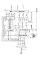
図1に、上記3相電動機及びその制御装置の全体構成を示す。 FIG. 1 shows the overall configuration of the three-phase motor and its control device.
図示されるように、3相電動機であるDCブラシレスモータ(モータ2)の3つの相(U相、V相、W相)には、インバータ10が接続されている。このインバータ10は、3相インバータであり、3つの相のそれぞれに対応したスイッチング素子12,14とスイッチング素子16,18とスイッチング素子20,22との並列接続体を備えて構成されている。更に、インバータ10は、各スイッチング素子12〜22に逆並列に接続されたダイオード24〜34を備えている。そして、スイッチング素子12及びスイッチング素子14を直列接続する接続点がモータ2のU相と接続されている。また、スイッチング素子16及びスイッチング素子18を直列接続する接続点がモータ2のV相と接続されている。更に、スイッチング素子20及びスイッチング素子22を直列接続する接続点がモータ2のW相と接続されている。ちなみに、これらスイッチング素子12〜22は、本実施形態では、絶縁ゲートバイポーラトランジスタ(IGBT)によって構成されている。
As illustrated, an
インバータ10の各1組のスイッチング素子12,14とスイッチング素子16,18とスイッチング素子20,22との両端には、平滑コンデンサ40を介してバッテリ42の電圧が印加されている。
The voltage of the
一方、マイクロコンピュータ(マイコン50)は、中央処理装置(CPU50a)や、読み出し専用メモリ(ROM)やランダムアクセスメモリ(RAM)等からなるメモリ50b、タイマ50c、レジスタ50d、一致検出器50e、出力ポート50f等を備えて構成されている。ここで、CPU50aは、定期的な演算周期に加えて、一致検出器50eの立ち上がりエッジをトリガとして、メモリ50b内のROMに記憶されているプログラムを実行する。このプログラムの実行は、各種演算パラメータ値をメモリ50b内のRAMに一時的に記憶させつつ行われる。一致検出器50eは、CPU50aによって任意の値に設定されるレジスタ50dの値と、所定周期で増加していくタイマ50cの値とを入力として、これらが一致するときに論理「1」のパルス信号を出力する。
On the other hand, the microcomputer (microcomputer 50) includes a central processing unit (
上記マイコン50は、モータ2の出力軸の回転角度を検出する位置センサ52や、U相及びV相に流れる電流を検出する電流センサ54,56の検出結果を取り込む。そして、マイコン50は、W相に流れる電流を、キルヒホッフの法則に基づき、U相を流れる電流とV相を流れる電流とから算出する。そして、マイコン50は、上記モータ2の出力軸の回転角度や3つの相を流れるそれぞれの電流等に基づき、ゲート駆動回路58a〜58cを介してスイッチング素子12〜22を操作することで、モータ2の回転に関する物理量(出力軸から出力されるトルク等)を制御する。
The
図2に、マイコン50の行なう処理のうち、特にスイッチング素子12〜22を操作するための操作信号の生成に関する処理の機能ブロック図を示す。
FIG. 2 shows a functional block diagram of processing related to generation of an operation signal for operating the switching
図2において、回転速度算出部60は、位置センサ52によって検出されるモータ2の回転角度θに基づき、モータ2の回転速度を算出する部分である。一方、dq軸電流指令値算出部62は、回転速度算出部60によって算出される回転速度と外部から取り込まれる要求トルクとに基づき、要求トルクを生成するためのdq軸上の要求電流である第1指令値id1,iq1を算出する部分である。また、dq軸電流指令値算出部62は、回転速度算出部60によって算出される回転速度と外部から取り込まれる要求トルクとに基づき、dq軸上での第2指令値id2,iq2をも算出する。
In FIG. 2, the rotation
電流指令値切替部64は、上記第1指令値id1,iq1又は第2指令値id2,iq2のいずれかを選択して出力する部分である。2相3相変換部66は、上記電流指令値切替部64によって選択される最終的なdq軸上の指令値idc,iqcを3相の指令電流iuc,ivc,iwcに変換する部分である。この際、位置センサ52によって検出される回転角度θに、モータ2の極対数pを乗算することで算出される電気角度を用いる。
The current command
上記指令電流iuc,ivc,iwcは、それぞれヒステリシスコンパレータ70,72,74に入力される。また、ヒステリシスコンパレータ70,72,74には、電流センサ54によって検出される実電流iu、電流センサ56によって検出される実電流iv、減算部76において実電流iu,ivの和の「−1」倍として算出される実電流iwがそれぞれ取り込まれる。
The command currents iuc, ivc, iwc are input to
そして、ヒステリシスコンパレータ70では、指令電流iucによって定まるヒステリシス領域の上限及び下限と実電流iuとの大小に基づき、駆動パルスgucを出力する。最終スイッチング信号決定部80では、所定の条件下、駆動パルスgucを、上記パワースイッチング素子12,14をスイッチングする操作信号guとする。ヒステリシスコンパレータ72では、指令電流ivcによって定まるヒステリシス領域の上限及び下限と実電流ivとの大小に基づき、駆動パルスgvcを出力する。最終スイッチング信号決定部80では、所定の条件下、駆動パルスgvcを、上記パワースイッチング素子16,18をスイッチングする操作信号gvとする。ヒステリシスコンパレータ74では、指令電流iwcによって定まるヒステリシス領域の上限及び下限と実電流iwとの大小に基づき、駆動パルスgwcを出力する。最終スイッチング信号決定部80では、所定の条件下、駆動パルスgwcを、上記パワースイッチング素子20,22をスイッチングする操作信号gwとする。なお、これら操作信号gu,gv,gwが論理「H」であるとき、先の図1に示したゲート駆動回路58a〜58cでは、上側アームのスイッチング素子SW12,SW16,SW20をオンとして且つ下側アームのスイッチング素子SW14,SW18,SW22をオフとする。また、操作信号gu,gv,gwが論理「L」であるとき、先の図1に示したゲート駆動回路58a〜58cでは、上側アームのスイッチング素子SW12,SW16,SW20をオフとして且つ下側アームのスイッチング素子SW14,SW18,SW22をオンとする
これにより、図3にU相について示すように、指令電流iucよりもヒステリシス幅hysの「1/2」だけ大きい値と指令電流iucよりもヒステリシス幅hysの「1/2」だけ小さい値との間の領域(ヒステリシス領域)内に入るように、実電流iuが制御される。
The
ところで、実電流iu,iv,iwを指令電流iuc,ivc,iwcによって定まるヒステリシス領域内となるようにフィードバック制御する瞬時電流値制御をする場合、モータ2の回転速度が高い領域では、モータ2を流れる電流(より正確には、指令電流iuc,ivc,iwc)の一周期と駆動パルスgu,gv,gwの周期とが一致するいわゆる矩形波制御となる傾向にある。矩形波制御は、インバータ10の入力電圧(バッテリ42の電圧)に対するモータ2に印加される相間電圧の1次成分の実効値の比である電圧利用率が理論上最大となる制御である。しかし、モータ2の回転速度が高い領域では、モータ2の逆起電力がインバータ10の入力電圧と近似する。このため、実電流iu,iv,iwと指令電流iuc,ivc,iwcとの間に位相ずれを生じ、ひいてはモータ2のトルクを要求トルクとすることができなくなることについては上述したとおりである。
By the way, in the case of instantaneous current value control that performs feedback control so that the actual currents iu, iv, iw are within the hysteresis region determined by the command currents iuc, ivc, iwc, the
そこで、本実施形態では、回転速度が高い領域において、要求トルクを生成するための第1指令値id1,iq1に代えて、第2指令値id2,iq2を用いて瞬時電流値制御を行う。ここではまず、第2指令値id2,iq2に基づく3相の指令電流iuc2,ivc2,iwc2を、図4にU相について例示する態様にて生成する。 Therefore, in the present embodiment, instantaneous current value control is performed using the second command values id2 and iq2 instead of the first command values id1 and iq1 for generating the required torque in a region where the rotational speed is high. Here, first, the three-phase command currents iuc2, ivc2, and iwc2 based on the second command values id2 and iq2 are generated in the manner illustrated for the U-phase in FIG.
すなわち、3相の第2指令電流iuc2,ivc2,iwc2は、3相の第1指令電流iuc1,ivc1,iwc1よりもその振幅が大きく、且つ位相がずれたものとなっている。この第2指令電流iuc2,ivc2,iwc2は、第1指令電流iuc1,ivc1,iwc1と、矩形波制御により要求トルクを生成するための適切な駆動パルスguaとによって算出される。 That is, the three-phase second command currents iuc2, ivc2, and iwc2 are larger in amplitude and out of phase than the three-phase first command currents iuc1, ivc1, and iwc1. The second command currents iuc2, ivc2, iwc2 are calculated by the first command currents iuc1, ivc1, iwc1 and an appropriate drive pulse gua for generating the required torque by rectangular wave control.
すなわち、第2指令電流iuc2,ivc2,iwc2と第1指令電流iuc1,ivc1,iwc1との交差タイミングが、矩形波制御により要求トルクを生成するための適切な駆動パルスgua,guva,gwaの反転タイミングと一致するように、第2指令電流iuc2,ivc2,iwc2を生成する。これにより、瞬時電流値制御により生成される駆動パルスguc,gvc,gwcは、矩形波制御によって要求トルクを生成することのできる駆動パルスgua,gva,gwaと近似する。これは、以下の理由による。 That is, the inversion timing of the drive pulses gua, gua, and gwa suitable for generating the required torque based on the rectangular wave control based on the intersection timing of the second command currents iuc2, ivc2, and iwc2 and the first command currents iuc1, ivc1, and iwc1. The second command currents iuc2, ivc2, and iwc2 are generated so as to match. Thus, the drive pulses guc, gvc, gwc generated by the instantaneous current value control approximate to the drive pulses gua, gva, gwa that can generate the required torque by the rectangular wave control. This is due to the following reason.
時刻t1においては、第1指令電流iuc1よりも第2指令電流iuc2の方が小さい。このため、実電流が要求トルクを生成するための要求電流(すなわち、第1指令電流iuc1)に追従しているとすると、第2指令電流iuc2を用いたときのヒステリシスコンパレータ72の出力する駆動パルスgucは、論理「L」となる。その後、第2指令電流iuc2が第1指令電流iuc1と交差するときには、実電流iuと第2指令電流iuc2との大小関係が逆転する。ここで、第2指令電流iuc2の振幅を大きく取ることにより、ヒステリシスコンパレータ72の出力する駆動パルスgucも、時刻t2近傍で論理反転する。このため、駆動パルスgucを、矩形波制御によって要求トルクを生成するためのパルス信号とすることができる。 At time t1, the second command current iuc2 is smaller than the first command current iuc1. Therefore, assuming that the actual current follows the required current for generating the required torque (that is, the first command current iuc1), the drive pulse output from the hysteresis comparator 72 when the second command current iuc2 is used. guc is logical “L”. Thereafter, when the second command current iuc2 intersects the first command current iuc1, the magnitude relationship between the actual current iu and the second command current iuc2 is reversed. Here, by increasing the amplitude of the second command current iuc2, the drive pulse guc output from the hysteresis comparator 72 is also logically inverted in the vicinity of time t2. For this reason, the drive pulse guc can be used as a pulse signal for generating the required torque by the rectangular wave control.
なお、図中、駆動パルスguaは、その波高値が第2指令電流iuc2と一致しているが、駆動パルスguの電圧の基準と第2指令電流iuc2の電流の基準とを調整することで便宜上一致させているに過ぎない。 In the figure, the peak value of the drive pulse gua coincides with the second command current iuc2, but for convenience, the voltage reference of the drive pulse gu and the current reference of the second command current iuc2 are adjusted. It just matches.
以下、マイコン50における第2指令電流に基づく瞬時電流値制御の処理手法について説明する。
Hereinafter, a processing method of instantaneous current value control based on the second command current in the
図5に、上記電流指令値切替部64による処理の手順を示す。この処理は、例えば所定周期で繰り返し実行される。
FIG. 5 shows a processing procedure by the current command
この一連の処理では、まずステップS10において、要求トルクが規定トルクαより大きく且つ回転速度が規定回転速度βよりも大きいか否かを判断する。この判断は、モータ2の逆起電力とインバータ10の入力電圧とが近似するか否かを判断するためのものである。そして、大きくないと判断されるときには、ステップS12において第1指令値id1,iq1が選択され、大きいと判断されるときには、ステップS14において第2指令値id2,iq2が選択される。
In this series of processes, first, in step S10, it is determined whether or not the required torque is larger than the prescribed torque α and the rotational speed is larger than the prescribed rotational speed β. This determination is for determining whether the back electromotive force of the
図6に、dq軸電流指令値算出部62による第1指令値id1,iq1及び第2指令値id2,iq2の算出処理の手順を示す。この処理は、例えば先の図5のステップS10において肯定判断されているときに所定周期で繰り返し実行される。
FIG. 6 shows the procedure for calculating the first command values id1, iq1 and the second command values id2, iq2 by the dq-axis current command
この一連の処理では、まずステップS20において、要求トルクと回転速度とから矩形波制御におけるスイッチング素子12〜22のオン操作のタイミング(スイッチング位相T3)と、3相における第2指令電流の振幅A2とを算出する。ここで、矩形波制御のスイッチング位相T3は、要求トルク及び回転速度とスイッチング位相T3との関係を、予めシミュレーションや実験等によって求めておく。また、第2指令電流の振幅A2は、インバータ10の最大定格電流に「2」の平方根を乗算した値Amax以下とすることが望ましい。すなわち、モータ2を流れる電流が値Amaxとなるときにインバータ10を流れる電流が最大定格電流と等しくなる。このため、振幅A2を値Amax以下とすることで、モータ2を流れる電流がインバータ10の最大定格電流を越えるときには、瞬時電流値制御により電流を減少させる側にフィードバック制御される。このため、モータ2を流れる電流がインバータ10の最大定格電流を越えることを抑制することができる。この第2指令電流の振幅A2は固定値としてもよいが、第1指令電流A1の振幅が大きいほど大きくなるようにすることが望ましい。これにより、実電流iu,iv,iwが、要求トルクを生成するための要求電流値(第1指令電流)から大きく離間することを回避することができる。
In this series of processes, first, in step S20, the ON operation timing (switching phase T3) of the switching
続くステップS22では、第1指令電流iuc1の位相T1と、第1指令電流iuc1,ivc1,iwc1の振幅A1とを算出する。ここで、第1指令電流iuc1は、電気角速度wを用いて以下の式によって表現される。なお、電気角速度wは、モータ2の極対数pと回転速度ω(rpm)とを用いて「w=2πpω/60」にて定義される。
In the subsequent step S22, the phase T1 of the first command current iuc1 and the amplitude A1 of the first command currents iuc1, ivc1, iwc1 are calculated. Here, the first command current iuc1 is expressed by the following equation using the electrical angular velocity w. The electrical angular velocity w is defined as “w = 2πpω / 60” using the number of pole pairs p of the
A1×sin(w×t−T1) …(c1)
また、位相T1は、「arctan(−id1/−iq1)」によって定義される。また、振幅A1は、第1指令値id1,iq1のそれぞれの2乗の和の「2/3」倍の平方根である。
A1 × sin (w × t−T1) (c1)
The phase T1 is defined by “arctan (−id1 / −iq1)”. The amplitude A1 is a square root of “2/3” times the sum of the squares of the first command values id1 and iq1.
続くステップS24では、第2指令電流iuc2の位相T2を算出する。 In the subsequent step S24, the phase T2 of the second command current iuc2 is calculated.
ここで、第2指令電流iuc2は、下記の式によって表現される。 Here, the second command current iuc2 is expressed by the following equation.
A2×sin(w×t−T2) …(c2)
このため、上記の式(c1)と式(c2)とが等しくなるときの位相がスイッチング位相T3であるとして下記の式が成立する。
A2 × sin (w × t−T2) (c2)
Therefore, the following equation is established assuming that the phase when the above equation (c1) and equation (c2) are equal is the switching phase T3.
A1×sin(T3−T1)=A2×sin(T3−T2)
したがって、位相T2は、下記の式(c3)によって算出することができる。
T2=T3−arcsin{(A1/A2)×sin(T3−T1)}…(c3)
続くステップS26においては、第2指令値id2,iq2を以下の式によって算出する。
A1 * sin (T3-T1) = A2 * sin (T3-T2)
Therefore, the phase T2 can be calculated by the following equation (c3).
T2 = T3-arcsin {(A1 / A2) × sin (T3-T1)} (c3)
In the subsequent step S26, the second command values id2, iq2 are calculated by the following formula.
id2=−A2×sin(T2)
iq2=−A2×cos(T2)
図7に、上記第2指令値id2,iq2を用いた瞬時電流値制御による実電流の挙動のシミュレーション結果を示す。図7では、便宜上、U相についてのシミュレーション結果を示している。図示されるように、実電流iuは、要求トルクを生成するための要求電流である第1指令電流iuc1に好適に追従している。これに対し、高回転速度において第1指令電流による瞬時電流値制御をする場合のシミュレーション結果を図8に示す。この場合、実電流iuの第1指令電流iuc1に対する追従性が悪いため、モータ2の出力トルクが要求トルクからずれたものとなる。
id2 = −A2 × sin (T2)
iq2 = −A2 × cos (T2)
FIG. 7 shows a simulation result of the actual current behavior by the instantaneous current value control using the second command values id2 and iq2. In FIG. 7, the simulation result about the U phase is shown for convenience. As shown in the figure, the actual current iu preferably follows the first command current iuc1 that is a required current for generating the required torque. On the other hand, FIG. 8 shows a simulation result when instantaneous current value control is performed with the first command current at a high rotational speed. In this case, since the followability of the actual current iu to the first command current iuc1 is poor, the output torque of the
このように、第2指令電流iuc,ivc2,iwc2を用いて瞬時電流値制御を行うことで、瞬時電流値制御によって矩形波制御を模擬することができる。ただし、瞬時電流値制御を用いた場合には、スイッチング操作状態の切り替えタイミングが、制御タイミング間の時間間隔(制御周期)に依存するため、切り替えタイミングが矩形波制御によって要求されるタイミングから遅延するおそれがある。以下、これについて詳述する。 Thus, by performing the instantaneous current value control using the second command currents iuc, ivc2, and iwc2, the rectangular wave control can be simulated by the instantaneous current value control. However, when the instantaneous current value control is used, the switching timing of the switching operation state depends on the time interval (control cycle) between the control timings, so the switching timing is delayed from the timing required by the rectangular wave control. There is a fear. This will be described in detail below.
図9に、第2指令電流iuc2,ivc2,iwc2を用いた瞬時電流制御によるスイッチング素子12〜22の操作状態の切り替えのうちU相を例示する。図示されるように、制御タイミングt11においては、図中太線にて示す実電流iuは、1点鎖線にて示す第2指令電流iuc2に応じて定まるヒステリシス領域(図中、細線内)よりも上側にある。そして、次の制御タイミングt12においては、実電流iuがヒステリシス領域内に入っている。このため、この段階では、ヒステリシスコンパレータ70の出力する駆動パルスgucは未だ論理反転しない。これに対し、その次の制御タイミングt13においては、実電流iuがヒステリシス領域よりも下側となる。このため、この制御タイミングt13において、ヒステリシスコンパレータ70の駆動パルスgucが論理反転し、スイッチング操作が切り替えられる。このため、要求トルクを生成するためのスイッチング操作状態の切り替えタイミングTPに対して実際のタイミングRPが遅延したものとなり、出力トルクと要求トルクとの間に誤差が生じる。
FIG. 9 illustrates the U phase among the switching of the operation states of the switching
この問題を回避するためにヒステリシス領域の上限及び下限間の幅(ヒステリシス幅)を狭めることも考えられるが、ヒステリシス幅を狭めると、要求トルクを生成するためのスイッチング操作状態の切り替えタイミングTPよりも実際のタイミングが進角側となりやすい。このため、こうした手法によっても、やはり出力トルクと要求トルクとの間に誤差が生じる。 In order to avoid this problem, the width between the upper limit and the lower limit of the hysteresis region (hysteresis width) may be narrowed. However, when the hysteresis width is narrowed, the switching operation state switching timing TP for generating the required torque is reduced. The actual timing tends to be on the advance side. For this reason, even with such a method, an error still occurs between the output torque and the required torque.
そこで本実施形態では、第1指令電流iuc1,ivc1,iwc1と第2指令電流iuc2,ivc2,iwc2との交点となるタイミング、すなわち矩形波制御によって要求トルクを生成するためのスイッチング操作状態の切り替えタイミングにおいて、瞬時電流値制御によって未だ切り替えがなされていないときには、強制的に切り替えを行う。こうした処理を行うべく、本実施形態では、先の図2に示すように、第2指令値id2,iq2が用いられているときに第1指令値id1,iq1を3相の第1指令電流iuc1,ivc1,iwc1に変換する2相3相変換部82を備えている。そして、スイッチングタイミング算出部84では、第2指令値id2,iq2が用いられているときに、第1指令電流iuc1,ivc1,iwc1と第2指令電流iuc2,ivc2,iwc2とが交わるタイミングを算出する。そして、交わるタイミングにおいて、スイッチング操作状態の切り替えをさせるべく、交わるタイミングまでの所要時間Tu,Tv,Twとスイッチング状態の指示信号Su,Sv,Swとを最終スイッチング信号決定部80に出力する。これにより、最終スイッチング信号決定部80では、所要時間Tu,Tv,Twの経過時において瞬時電流値制御によってスイッチング操作状態の切り替えが未だなされていないときには、指示信号Su,Sv,Swに基づきスイッチング操作状態の切り替えを行う。
Therefore, in the present embodiment, the timing at which the first command currents iuc1, ivc1, iwc1 and the second command currents iuc2, ivc2, iwc2 intersect, that is, the switching timing of the switching operation state for generating the required torque by the rectangular wave control. When the switching is not yet performed by the instantaneous current value control, the switching is forcibly performed. In order to perform such processing, in the present embodiment, as shown in FIG. 2, when the second command values id2 and iq2 are used, the first command values id1 and iq1 are converted into the three-phase first command current iuc1. , Ivc1, iwc1 is provided with a two-phase / three-
図10に、スイッチングタイミング算出部84等の行う処理のうち、特にU相のスイッチングタイミングの算出にかかる処理の手順を示す。この処理は、マイコン50により、例えば所定周期で繰り返し実行される。なお、V相、W相の処理についても、図10に示す処理と同様であるため、その説明を割愛する。
FIG. 10 shows a procedure of processing related to calculation of the switching timing of the U phase, among processing performed by the switching
この一連の処理では、まずステップS30において、第2指令値id2,iq2による瞬時電流値制御がなされているときであるか否かを判断する。ここでは、先の図2に示した電流指令値切替部64から第2指令値id2,iq2を選択している旨の信号が出力されているか否かを判断する。そして、ステップS30において第2指令値id2,iq2が選択されていると判断されるときには、ステップS32において、U相の第1指令電流iuc1と、制御周期内でのその増加量Δiuc1とを算出する。ここで、U相の第1指令電流iuc1は、dq軸上(静止座標系)での第1指令値id1,iq1を上記2相3相変換部82によって3相(回転座標系)での第1指令電流iuc1,ivc1,iwc1に変換することで行うことができる。また、増加量Δiuc1については、テイラー級数の1次の項にて近似的に算出する。以下、これについて説明する。
In this series of processes, first, in step S30, it is determined whether or not the instantaneous current value control is performed by the second command values id2 and iq2. Here, it is determined whether or not a signal indicating that the second command values id2 and iq2 are selected is output from the current command
dq軸上での電流id,iqを、3相の電流iu,iv,iw(ここでは、実電流iu,iv,iwと同一の符号を用いているが、実電流iu,iv,iwに限らない)に変換する2相3相変換は、以下の態様にて行われる。
iu=sqrt(2/3){cos(w×t) ×id −sin(w×t) ×iq}
iv=sqrt(2/3){cos(w×t−2π/3) ×id −sin(w×t-2π/3) ×iq}
iw=sqrt(2/3){cos(w×t) ×id −sin(w×t+2π/3) ×iq}
上記各式の両辺を時間微分すると、下記の式となる。
d(iu)/dt=w×sqrt(2/3){cos(w×t) ×(-iq) −sin(w×t) ×id}
d(iv)/dt=w×sqrt(2/3){cos(w×t−2π/3) ×(-iq) −sin(w×t-2π/3) ×id}
d(iw)/dt=w×sqrt(2/3){cos(w×t) ×(-iq) −sin(w×t+2π/3) ×id}
上記の式からわかるように、時間微分演算は、2相3相変換において、電流ベクトル(id,iq)を変換対象とする代わりに、電流ベクトル(−iq,id)を変換対象とすることで行うことができる。図11に、第1指令電流iuc1,ivc1,iwc1及び後述する第2指令電流iuc2,ivc2,iwc2の増加量Δiu,Δiv,Δiwの算出手法を示す。図示されるように、電流ベクトル(−iq,id)を2相3相変換部90にて変換した後、その出力に、乗算器92,94,96によって電気角速度wと制御周期Tとの乗算値を乗算することで、増加量Δiuc1,Δivc1,Δiwc1を算出することができる。
The currents id and iq on the dq axis are represented by three-phase currents iu, iv, and iw (here, the same signs as the actual currents iu, iv, and iw are used, but are limited to the actual currents iu, iv, and iw). 2 phase to 3 phase conversion is performed in the following manner.
iu = sqrt (2/3) {cos (w × t) × id−sin (w × t) × iq}
iv = sqrt (2/3) {cos (w × t−2π / 3) × id−sin (w × t−2π / 3) × iq}
iw = sqrt (2/3) {cos (w × t) × id−sin (w × t + 2π / 3) × iq}
When both sides of the above equations are differentiated with respect to time, the following equation is obtained.
d (iu) / dt = w × sqrt (2/3) {cos (w × t) × (−iq) −sin (w × t) × id}
d (iv) / dt = w × sqrt (2/3) {cos (w × t−2π / 3) × (−iq) −sin (w × t−2π / 3) × id}
d (iw) / dt = w × sqrt (2/3) {cos (w × t) × (−iq) −sin (w × t + 2π / 3) × id}
As can be seen from the above equation, the time differentiation operation is performed by using the current vector (−iq, id) as the conversion target instead of the current vector (id, iq) as the conversion target in the two-phase / three-phase conversion. It can be carried out. FIG. 11 shows a method of calculating the increments Δiu, Δiv, Δiw of the first command currents iuc1, ivc1, iwc1 and second command currents iuc2, ivc2, iwc2, which will be described later. As shown in the figure, after the current vector (−iq, id) is converted by the two-phase / three-
先の図10のステップS32の処理が完了すると、ステップS34において、U相の第2指令電流iuc2と、制御周期内でのその増加量Δiu2とを算出する。ここで、U相の第2指令電流iuc2については、先の図2に示した2相3相変換部66によって算出する。また、増加量Δiu2については、先の図11に示した手法により算出する。
When the process of step S32 of FIG. 10 is completed, in step S34, the U-phase second command current iuc2 and the amount of increase Δiu2 within the control cycle are calculated. Here, the U-phase second command current iuc2 is calculated by the two-phase / three-
続くステップS36においては、次回の第1指令電流の予測値iuc1^と第2指令電流の予測値iuc2^とを算出する。ここでは、今回の第1指令電流iuc1に増加量Δiuc1を加算することで予測値iuc1^を算出し、今回の第2指令電流iuc2に増加量Δiu2を加算することで予測値iuc2^を算出する。そして、ステップS38では、今回の第1指令電流iuc1及び第2指令電流iuc2の大小関係に対し、予測値iuc1^及び予測値iuc2^の大小関係が逆転しているか否かを判断する。この処理は、次回の制御タイミングまでの期間に、第1指令電流iuc1と第2指令電流iuc2とが交わるか否かを判断するものである。すなわち、図12に示すように、今回の制御タイミングt21と次回の制御タイミングt23との間のタイミングt22で第1指令電流iuc1と第2指令電流iuc2とが交わる場合、上記大小関係の逆転が生じる。このため、逆転に基づき交わるか否かを判断することができる。 In the subsequent step S36, the next predicted value iuc1 ^ of the first command current and the predicted value iuc2 ^ of the second command current are calculated. Here, the predicted value iuc1 ^ is calculated by adding the amount of increase Δiuc1 to the current first command current iuc1, and the predicted value iuc2 ^ is calculated by adding the amount of increase Δiu2 to the current second command current iuc2. . In step S38, it is determined whether the magnitude relationship between the predicted value iuc1 ^ and the predicted value iuc2 ^ is reversed with respect to the magnitude relationship between the first command current iuc1 and the second command current iuc2. This process is to determine whether or not the first command current iuc1 and the second command current iuc2 intersect during the period up to the next control timing. That is, as shown in FIG. 12, when the first command current iuc1 and the second command current iuc2 intersect at a timing t22 between the current control timing t21 and the next control timing t23, the magnitude relationship is reversed. . For this reason, it is possible to determine whether or not to intersect based on the reverse rotation.
そしてステップS38において逆転が生じると判断されるときには、ステップS40において現在の制御タイミングから上記交わるタイミングまでの所要時間Tuを算出する。ここでは、第2指令電流iuc2の時間微分値「d(iuc2)/dt」に対する第1指令電流iuc1の時間微分値「d(iuc1)/dt」の差で、現在の第1指令電流iuc1に対する第2指令電流iuc2の差を除算することで、所要時間Tuを算出する。 If it is determined in step S38 that reverse rotation will occur, the required time Tu from the current control timing to the above intersection timing is calculated in step S40. Here, the difference between the time differential value “d (iuc1) / dt” of the first command current iuc1 with respect to the time differential value “d (iuc2) / dt” of the second command current iuc2 and the current first command current iuc1 The required time Tu is calculated by dividing the difference of the second command current iuc2.
続くステップS42においては、今回の第1指令電流iuc1が今回の第2指令電流iuc2よりも大きく且つ、第1指令電流の予測値iuc1^が第2指令電流の予測値iuc2^よりも小さいか否かを判断する。この処理は、U相のスイッチング素子12,14のいずれをオン状態とする操作に切り替えるかを判断するものである。そして、ステップS42において肯定判断されるときにはステップS44において指示信号Suを「1」とすることで、スイッチング素子12がオン且つスイッチング素子14がオフとなるように切り替える旨指示する。また、ステップS42において否定判断されるときには、ステップS46において指示信号Suを「0」とすることで、スイッチング素子12がオフ且つスイッチング素子14がオンとなるように切り替える旨指示する。
In subsequent step S42, whether or not the current first command current iuc1 is larger than the current second command current iuc2 and the predicted value iuc1 ^ of the first command current is smaller than the predicted value iuc2 ^ of the second command current. Determine whether. This process is to determine which of the
これに対し、上記ステップS30において第2指令電流が選択されていないと判断されるときには、ステップS48において、所要時間Tuを「−1」にセットする。なお、ステップS44〜S48の処理が完了するときには、この一連の処理を一旦終了する。 On the other hand, when it is determined in step S30 that the second command current is not selected, the required time Tu is set to “−1” in step S48. When the processes in steps S44 to S48 are completed, this series of processes is temporarily terminated.
図13に、最終スイッチング信号決定部80の行う処理のうち、特にU相のスイッチング制御に関する処理の手順を示す。詳しくは、図13(a)には、U相のスイッチング制御に関する処理のうち先の図10に示した処理に引き続いて実行される処理を示し、また、図13(b)には、一致検出器50eによって一致が検出されるタイミングでなされる割り込み処理を示す。なお、V相、W相の処理についても、U相と同様にして行うことができるため、その説明を割愛する。
FIG. 13 shows a procedure of processing related to U-phase switching control among the processing performed by the final switching
図13(a)に示す一連の処理では、まずステップS50において、所要時間Tuが「0」以上であるか否かを判断する。この処理は、先の図10に示した処理によって、指示信号Su及び所要時間Tuが設定されることにより、指示信号Suに基づくスイッチング操作を優先させる状況か否かを判断するものである。そして、所要時間Tuが「0」以上であると判断されるときには、ステップS52において、先の図1に示したタイマ50cの現在の値に所要時間Tuを加算した値をレジスタ50dにセットする。これにより、所要時間Tu経過時にタイマ50cの値とレジスタ50dの値との一致が一致検出器50eによって検出されるため、図13(b)に示す割り込み処理が実行される。すなわち、ステップS64において指示信号Suを出力ポート50fにセットする。これにより、指示信号Suが強制的に出力されるため、瞬時電流値制御による駆動パルスgucが論理反転していない場合、スイッチング素子12、14の操作が強制的に切り替えられることとなる。そして、ステップS66においては、指示信号Suによる強制的な切り替えがなされた旨を示す割り込み履歴フラグをセットする。
In the series of processes shown in FIG. 13A, first, in step S50, it is determined whether or not the required time Tu is “0” or more. This process is to determine whether or not the switching operation based on the instruction signal Su is prioritized by setting the instruction signal Su and the required time Tu by the process shown in FIG. Then, when it is determined that the required time Tu is “0” or more, in step S52, a value obtained by adding the required time Tu to the current value of the
図13(a)に示すステップS54では、割り込み履歴フラグがセットされているか否かを判断する。この処理は、瞬時電流値制御による駆動パルスgucを無効化する処理を行うか否かを判断するためのものである。これは、「第1指令電流iuc1と第2指令電流iuc2とが交わるタイミングで強制的にスイッチング操作状態の切り替えがなされるのは、指示信号Suと駆動パルスgucとが互いに矛盾する指令信号となっているときである」ことに鑑みてなされる処理である。このため、駆動パルスgucを無効としないと、矩形波制御のための適切なタイミングにてスイッチング操作状態を切り替えたにもかかわらず瞬時電流値制御によってスイッチング操作状態が再度切り替えられるおそれがある。 In step S54 shown in FIG. 13A, it is determined whether or not an interrupt history flag is set. This process is for determining whether or not to invalidate the drive pulse guc by the instantaneous current value control. This is because “the switching operation state is forcibly switched at the timing at which the first command current iuc1 and the second command current iuc2 cross each other is a command signal in which the instruction signal Su and the drive pulse guc are inconsistent with each other. This is a process that is performed in view of “when it is.” For this reason, if the drive pulse guc is not invalidated, the switching operation state may be switched again by the instantaneous current value control even though the switching operation state is switched at an appropriate timing for the rectangular wave control.
すなわち、割り込み履歴フラグがオンとされていると判断されるときには、駆動パルスgucを無効化すべく、ステップS56に移行する。ステップS56では、割り込み発生後の制御タイミングの発生回数をカウントする発生回数カウンタの値が所定値γ以上であるか否かを判断する。この処理は、駆動パルスgucの無効化を解除してもよいか否かを判断するものである。ここで、所定値γは、駆動パルスgucと指示信号Suとの指示内容が互いに異なり得ると想定される期間にわたって駆動パルスgucを無効化することのできる値であって、且つ極力小さい値に設定されている。これは、実電流iuが第1指令電流iuc1から過度に離間することのないようにするための設定である。すなわち、駆動パルスgucを極力早期に有効化することで、瞬時電流値制御による電流のフィードバック制御を開始することができ、ひいては実電流iuが第1指令電流iuc1から過度に離間する状況を回避することができる。ここでは、特に、無効化の期間が第1指令電流iuc1の半周期「2π/w」よりも極力短い時間とする。この期間は、ヒステリシス幅の設定に依存するが、概ね「20〜200μs」でよい。 That is, when it is determined that the interrupt history flag is turned on, the process proceeds to step S56 to invalidate the drive pulse guc. In step S56, it is determined whether or not the value of the occurrence count counter that counts the occurrence count of the control timing after the occurrence of the interrupt is equal to or greater than a predetermined value γ. This process is to determine whether or not the invalidation of the drive pulse guc may be cancelled. Here, the predetermined value γ is a value that can invalidate the drive pulse guc over a period in which the instruction contents of the drive pulse guc and the instruction signal Su can be different from each other, and is set to a value that is as small as possible. Has been. This is a setting for preventing the actual current iu from being excessively separated from the first command current iuc1. That is, by enabling the drive pulse guc as early as possible, current feedback control by instantaneous current value control can be started, and as a result, a situation where the actual current iu is excessively separated from the first command current iuc1 is avoided. be able to. Here, in particular, the invalidation period is set to a time shorter than the half cycle “2π / w” of the first command current iuc1. Although this period depends on the setting of the hysteresis width, it may be approximately “20 to 200 μs”.
そして発生回数カウンタが所定値γ未満であると判断されるときには、ステップS58において、発生回数カウンタをインクリメントする。これに対し、発生回数カウンタが所定値γ以上であると判断されるときには、割り込み履歴フラグ及び発生回数カウンタをリセットする。 If it is determined that the occurrence counter is less than the predetermined value γ, the occurrence counter is incremented in step S58. On the other hand, when it is determined that the occurrence counter is greater than or equal to the predetermined value γ, the interrupt history flag and the occurrence counter are reset.
これに対し、上記ステップS54において割り込み履歴フラグがセットされていないと判断されるときには、ステップS62において、駆動パルスgucを出力ポート50fにセットすることで、駆動パルスgucを有効とする。このため、瞬時電流値制御として第1指令電流iuc1が用いられているときと、第2指令電流iuc2が用いられているときであって且つ割り込み履歴フラグがリセットされているときには、駆動パルスgucが有効化されることとなる。
On the other hand, when it is determined in step S54 that the interrupt history flag is not set, the drive pulse guc is validated by setting the drive pulse guc to the
なお、ステップS58,S60,S62の処理が完了するときには、この一連の処理を一旦終了する。 When the processes in steps S58, S60, and S62 are completed, this series of processes is temporarily terminated.
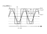
上記第2指令電流iuc2の振幅A2は、タイマ50cの計時周期Tc、ディジタル処理に伴う第2指令電流iuc2の最小単位量Ad、第2指令電流iuc2が選択される際の最小の電気角速度ωmin(先の図5のステップS10の規定回転速度βに極対数pを乗算した値)を用いて、「Ad/(ωmin×Tc)」以上となるように設定する。これは、以下の理由による。図14に示すように、制御タイミング間の時間間隔(制御周期T)とタイマの計時周期Tcとによって、制御周期Tの間の計時動作回数を、「T/Tc」と表すことができる。一方、制御周期Tの間に、第2指令電流iuc2が増加する回数を、最小単位量Adと、電気角速度ωと、第2指令電流iuc2の振幅A2とによって表現すると、「ω×A2×T/Ad」となる。ここでは、第1指令電流iuc1及び第2指令電流iuc2の交点近傍における第2指令電流の変化速度が「ω×A2」で近似できることを用いている。制御周期T内では第1指令電流iuc1の変化は無視できるとものとすると、第2指令電流iuc2が第1指令電流iuc1と交わるタイミングの算出精度を計時動作の精度と同程度以上とするためには、「ω×A2×T/Ad≧T/Tc」とする必要がある。これから、「A2≧Ad/(ω×Tc)」が求まる。この式から明らかなように、右辺はωが小さいほど大きくなる。よって、第2指令電流iuc2が選択される際の最小の電気角速度ωminを用いて、振幅A2が満たすべき条件は、「Ad/(ωmin×Tc)」以上であることとなる。
The amplitude A2 of the second command current iuc2 includes the timing period Tc of the
図15に、本実施形態にかかるトルク制御のシミュレーション結果を示す。図示されるように、指示信号Suによる強制的な切り替え処理を用いることで、平均トルクと要求トルクとが一致し、要求トルクへの制御を高精度に行うことができている。これに対し、図16に、指示信号Suによる強制的な切り替えを行わず、第2指令電流iuc2による瞬時電流値制御を行った場合を示す。この場合、瞬時トルクが、実電流iuの2周期程度を周期として脈動し、トルク平均も要求トルクからずれたものとなる。 FIG. 15 shows a simulation result of torque control according to the present embodiment. As shown in the figure, by using the forced switching process based on the instruction signal Su, the average torque matches the required torque, and the control to the required torque can be performed with high accuracy. On the other hand, FIG. 16 shows a case where the instantaneous current value control by the second command current iuc2 is performed without the forced switching by the instruction signal Su. In this case, the instantaneous torque pulsates with a cycle of about two cycles of the actual current iu, and the torque average also deviates from the required torque.
以上詳述した本実施形態によれば、以下の効果が得られるようになる。 According to the embodiment described in detail above, the following effects can be obtained.
(1)第2指令電流iuc2,ivc2,iwc2(大振幅指令電流)が第1指令電流iuc1,ivc1,iwc1(要求電流)と交わるタイミングにおいて、瞬時電流値制御によってスイッチング操作状態の切り替えが未だなされていないとき、強制的に切り替えを行った。これにより、瞬時電流値制御によって矩形波制御の一端を担わせつつも、瞬時電流値制御によるスイッチング操作状態の切り替えタイミングが矩形波制御によって要求電流を生成するための切り替えタイミングに対して遅延することを回避することができる。 (1) At the timing when the second command currents iuc2, ivc2, iwc2 (large amplitude command current) intersect with the first command currents iuc1, ivc1, iwc1 (request current), switching of the switching operation state is not yet performed by instantaneous current value control. Forcibly switched when not. As a result, while switching one end of the rectangular wave control by the instantaneous current value control, the switching timing of the switching operation state by the instantaneous current value control is delayed with respect to the switching timing for generating the required current by the rectangular wave control. Can be avoided.
(2)強制的な切り替えがなされてから所定期間、瞬時電流値制御によるスイッチング操作状態の切り替えを禁止した。これにより、強制的な切り替えによって要求トルクを生成するために適切な位相で切り替えがなされているにもかかわらず、これが妨げられることを回避することができる。 (2) Switching of the switching operation state by the instantaneous current value control is prohibited for a predetermined period after the forced switching is performed. Accordingly, it is possible to avoid that this is hindered even though switching is performed at an appropriate phase in order to generate the required torque by forced switching.
(3)第2指令電流iuc2,ivc2,iwc2及び第1指令電流iuc1,ivc1,iwc1についての今回の制御タイミングの大小関係と次回の制御タイミングの大小関係の変化に基づき、第2指令電流iuc2,ivc2,iwc2と第1指令電流iuc1,ivc1,iwc1が次回の制御タイミングまでに交わるか否かを判断した。これにより、次回の制御タイミングまでの期間に交わるタイミングが生じるか否かを適切に判断することができる。 (3) Based on the change in the magnitude relationship between the current control timing and the next control timing with respect to the second command current iuc2, ivc2, iwc2 and the first command current iuc1, ivc1, iwc1, the second command current iuc2, It was determined whether ivc2, iwc2 and the first command currents iuc1, ivc1, iwc1 intersected by the next control timing. As a result, it is possible to appropriately determine whether or not a timing that intersects the period until the next control timing occurs.
(4)dq軸上での指令値id1,iq1,id2,iq2を2相3相変換部90によって変換することで第2指令電流iuc2,ivc2,iwc2及び第1指令電流iuc1,ivc1,iwc1の時間微分演算を行いつつ、次回の制御タイミングにおけるこれら第2指令電流iuc2,ivc2,iwc2及び第1指令電流iuc1,ivc1,iwc1をテイラー級数によって算出した。このように、2相3相変換部90を用いることで、テイラー級数を簡易に算出することができ、ひいては次回の制御タイミングにおける第2指令電流iuc2,ivc2,iwc2及び第1指令電流iuc1,ivc1,iwc1を簡易に予測することができる。
(4) The command values id1, iq1, id2, iq2 on the dq axis are converted by the two-phase / three-
(5)次回の制御タイミングにおける第2指令電流iuc2,ivc2,iwc2及び第1指令電流iuc1,ivc1,iwc1を、テイラー級数の1次の項までで近似した。これにより、次回の制御タイミングにおける第2指令電流iuc2,ivc2,iwc2及び第1指令電流iuc1,ivc1,iwc1をより簡易な処理にて算出することができる。 (5) The second command currents iuc2, ivc2, iwc2 and the first command currents iuc1, ivc1, iwc1 at the next control timing are approximated to the first order term of the Taylor series. Thereby, the second command currents iuc2, ivc2, iwc2 and the first command currents iuc1, ivc1, iwc1 at the next control timing can be calculated by a simpler process.
(6)第2指令電流iucの振幅A2を、タイマ50cの計時周期Tc、ディジタル処理に伴う第2指令電流iuc2の最小単位量Ad、第2指令電流iuc2が選択されるとき(矩形波制御がなされるとき)の最小電気角速度ωminを用いて、「Ad/(ωmin×Tc)」以上となるように設定した。これにより、第2指令電流iuc2が第1指令電流iuc1と交わるタイミングの算出精度を計時動作の精度と同程度以上とすることができる。
(6) When the amplitude A2 of the second command current iuc is selected from the timing period Tc of the
(7)所要時間Tuを、第2指令電流iuc2,ivc2,iwc2の時間微分値に対する第1指令電流iuc1,ivc1,iwc1の時間微分値の差によって第1指令電流iuc1,ivc1,iwc1に対する第2指令電流iuc2,ivc2,iwc2の差を除算した値として算出した。これにより、所要時間Tu,Tv,Twを簡易に算出することができる。 (7) The required time Tu is set to a second value for the first command currents iuc1, ivc1, iwc1 according to the difference of the time differential values of the first command currents iuc1, ivc1, iwc1 with respect to the time differential values of the second command currents iuc2, ivc2, iwc2. The difference was calculated as the difference between the command currents iuc2, ivc2, and iwc2. Thereby, the required times Tu, Tv, and Tw can be easily calculated.
(8)第2指令電流iuc2,ivc2,iwc2の振幅を、インバータ10の最大定格電流値に2の平方根を乗算した値以下とした。これにより、インバータ10を流れる電流の絶対値が最大定格電流を越えて大きくなることを好適に抑制することができる。
(8) The amplitude of the second command currents iuc2, ivc2, and iwc2 is set to be equal to or smaller than the value obtained by multiplying the maximum rated current value of the
(9)矩形波制御によって要求トルクを実現するためのスイッチング操作状態の切り替えタイミングにおいて、第2指令電流iuc2,ivc2,iwc2が第1指令電流iuc1,ivc1,iwc1と交わるように、第2指令電流iuc2,ivc2,iwc2を適合した。これにより、上記交わるタイミング近傍において瞬時電流値制御によりスイッチング操作状態を切り替えることができる。 (9) The second command current so that the second command currents iuc2, ivc2, and iwc2 intersect the first command currents iuc1, ivc1, and iwc1 at the switching timing of the switching operation state for realizing the required torque by the rectangular wave control. iuc2, ivc2, and iwc2 were matched. Thereby, the switching operation state can be switched by the instantaneous current value control in the vicinity of the intersecting timing.
(第2の実施形態)
以下、第2の実施形態について、先の第1の実施形態との相違点を中心に図面を参照しつつ説明する。
(Second Embodiment)
Hereinafter, the second embodiment will be described with reference to the drawings with a focus on differences from the first embodiment.
本実施形態では、次回の制御タイミングでの第2指令電流iuc2,ivc2,iwc2や第1指令電流iuc1,ivc1,iwc1を、テイラー級数の2次の項までを用いて近似する。この際、これらの2階微分値が、電流ベクトル(id,iq)を2相3相変換して且つ「−w×w」を乗算することで得られることに着目する。図17に、本実施形態にかかる第2指令電流iuc2,ivc2,iwc2の増加量Δiu2,Δiv2,Δiw2や第1指令電流iuc1,ivc1,iwc1の増加量Δiuc1,Δivc1,Δiwc1の算出処理を示す。 In the present embodiment, the second command currents iuc2, ivc2, iwc2 and the first command currents iuc1, ivc1, iwc1 at the next control timing are approximated using up to the second order terms of the Taylor series. At this time, it is noted that these second-order differential values are obtained by performing two-phase three-phase conversion on the current vector (id, iq) and multiplying by “−w × w”. FIG. 17 shows a calculation process of the increase amounts Δiu2, Δiv2, Δiw2 of the second command currents iuc2, ivc2, iwc2 and the increase amounts Δiuc1, Δivc1, Δiwc1 of the first command currents iuc1, ivc1, iwc1 according to the present embodiment.
図示されるように、dq軸上の電流ベクトル(id,iq)のq軸成分を乗算器100によって符号を反転させた後、成分を入れ替えることで電流ベクトル(−iq,id)を生成する。そして、これを2相3相変換部102にて3相の電流ベクトルに変換した後、乗算器104,106,108にて「wT」を乗算することで、テイラー級数の1次の項を算出する。一方、dq軸上の電流ベクトル(id,iq)を、2相3相変換部110にて3相の電流ベクトルに変換した後、乗算器112,114,116にて「(−1/2)w×w×T×T」を乗算することで、テイラー級数の2次の項を算出する。そして、加算器118,120,122にて、1次の項と2次の項とを加算することで、第2指令電流iuc2,ivc2,iwc2の増加量Δiu2,Δiv2,Δiw2や第1指令電流iuc1,ivc1,iwc1の増加量Δiuc1,Δivc1,Δiwc1を算出する。
As shown in the figure, the sign of the q-axis component of the current vector (id, iq) on the dq axis is inverted by the
以上説明した本実施形態によれば、先の第1の実施形態の上記(1)〜(4)、(6)〜(9)の効果に加えて、更に以下の効果が得られるようになる。 According to this embodiment described above, in addition to the effects (1) to (4) and (6) to (9) of the first embodiment, the following effects can be obtained. .
(10)次回の制御タイミングにおける第2指令電流iuc2,ivc2,iwc2及び第1指令電流iuc1,ivc1,iwc1を、テイラー級数の2次の項までで近似した。これにより、次回の制御タイミングにおける第2指令電流iuc2,ivc2,iwc2及び第1指令電流iuc1,ivc1,iwc1をより高精度に算出することができる。 (10) The second command currents iuc2, ivc2, iwc2 and the first command currents iuc1, ivc1, iwc1 at the next control timing are approximated up to the second order term of the Taylor series. Thus, the second command currents iuc2, ivc2, iwc2 and the first command currents iuc1, ivc1, iwc1 at the next control timing can be calculated with higher accuracy.
(第3の実施形態)
以下、第3の実施形態について、先の第1の実施形態との相違点を中心に図面を参照しつつ説明する。
(Third embodiment)
Hereinafter, the third embodiment will be described with reference to the drawings with a focus on differences from the first embodiment.
図18に、本実施形態にかかる次回の制御タイミングにおける第2指令電流iuc2,ivc2,iwc2や第1指令電流iuc1,ivc1,iwc1の算出処理を示す。 FIG. 18 shows a calculation process of the second command currents iuc2, ivc2, iwc2 and the first command currents iuc1, ivc1, iwc1 at the next control timing according to the present embodiment.
図示されるように、電流ベクトル(id,iq)を2相3相変換部130にて3相の電流ベクトルに変換する際、電気角度として、次回の制御タイミングまでの回転角度間隔「wT」だけ現在の電気角度「θ×p」を進角させた角度を用いる。これにより、テイラー級数を用いることなく、次回の制御タイミングにおける第2指令電流の予測値iuc2^,ivc2^,iwc2^や第1指令電流の予測値iuc1^,ivc1^,iwc1^を算出することができる。
As shown in the figure, when the current vector (id, iq) is converted into a three-phase current vector by the two-phase / three-
以上説明した本実施形態によれば、先の第1の実施形態の上記(1)〜(3)、(6)〜(9)の効果に加えて、更に以下の効果が得られるようになる。 According to this embodiment described above, in addition to the effects (1) to (3) and (6) to (9) of the first embodiment, the following effects can be obtained. .
(11)次回の制御タイミングまでの回転角度間隔「wT」だけ現在の電気角度「θ×p」を進角させた角度を用いて2相3相変換を行うことで、次回の制御タイミングにおける第2指令電流の予測値iuc2^,ivc2^,iwc2^や第1指令電流の予測値iuc1^,ivc1^,iwc1^を算出した。これにより、次回の制御タイミングにおける第2指令電流の予測値iuc2^,ivc2^,iwc2^や第1指令電流の予測値iuc1^,ivc1^,iwc1^を簡易に算出することができる。 (11) Two-phase three-phase conversion is performed using an angle obtained by advancing the current electrical angle “θ × p” by the rotation angle interval “wT” until the next control timing, so that Predicted values iuc2 ^, ivc2 ^, iwc2 ^ of the two command currents and predicted values iuc1 ^, ivc1 ^, iwc1 ^ of the first command current were calculated. As a result, the predicted values iuc2 ^, ivc2 ^, iwc2 ^ of the second command current and the predicted values iuc1 ^, ivc1 ^, iwc1 ^ of the first command current at the next control timing can be easily calculated.
(第4の実施形態)
以下、第4の実施形態について、先の第1の実施形態との相違点を中心に図面を参照しつつ説明する。
(Fourth embodiment)
Hereinafter, the fourth embodiment will be described with reference to the drawings with a focus on differences from the first embodiment.
先の第1の実施形態では、線形近似によって、次回の制御タイミングにおける第2指令電流iuc2,ivc2,iwc2や第1指令電流iuc1,ivc1,iwc1を予測した。しかし、この場合、次回の制御タイミングにおける第2指令電流iuc2,ivc2,iwc2や第1指令電流iuc1,ivc1,iwc1の真の値に対して予測値が遅延するおそれがある。そしてこの場合には、矩形波制御によって要求トルクを生成するための適切なタイミングにてスイッチング操作状態の切り替えがなされないおそれがある。以下、これについて図19を用いて詳述する。 In the first embodiment, the second command currents iuc2, ivc2, iwc2 and the first command currents iuc1, ivc1, iwc1 at the next control timing are predicted by linear approximation. However, in this case, the predicted value may be delayed with respect to the true values of the second command currents iuc2, ivc2, iwc2 and the first command currents iuc1, ivc1, iwc1 at the next control timing. In this case, the switching operation state may not be switched at an appropriate timing for generating the required torque by the rectangular wave control. Hereinafter, this will be described in detail with reference to FIG.
図示されるように、制御タイミングt31においては、1点鎖線にて示される第2指令電流iuc2の方が2点鎖線にて示される第1指令電流iuc1より小さい。そして、このときに線形近似にて予測される次回の制御タイミングt32における第2指令電流iuc2の予測値も第1指令電流iuc1の予測値より小さい。このため、先の図10のステップS38において逆転が生じないと判断されるために、指示信号Su等の設定がなされない。しかし、図の例では、制御タイミングt32においては、第2指令電流iuc2が第1指令電流iuc1よりも大きくなっている。そして、この時点において次回の制御タイミングt33での第2指令電流iuc2や第1指令電流iuc1の予測値を算出すると、次回の制御タイミングt33までの間に、第2指令電流iuc2と第1指令電流iuc1とが交わらないと判断されることとなる。このため、矩形波制御によるスイッチング操作状態の切り替えに処理抜けが生じ、瞬時電流値制御の駆動パルスgucが論理反転するまでスイッチング操作状態の切り替えがなされないこととなり、切り替えに遅延が生じる。 As illustrated, at the control timing t31, the second command current iuc2 indicated by the one-dot chain line is smaller than the first command current iuc1 indicated by the two-dot chain line. At this time, the predicted value of the second command current iuc2 at the next control timing t32 predicted by the linear approximation is also smaller than the predicted value of the first command current iuc1. For this reason, since it is determined that the reverse rotation does not occur in step S38 of FIG. 10, the instruction signal Su or the like is not set. However, in the example of the figure, at the control timing t32, the second command current iuc2 is larger than the first command current iuc1. At this time, when the predicted values of the second command current iuc2 and the first command current iuc1 at the next control timing t33 are calculated, the second command current iuc2 and the first command current are calculated until the next control timing t33. It will be determined that iuc1 does not intersect. For this reason, a process omission occurs in switching of the switching operation state by the rectangular wave control, and the switching operation state is not switched until the drive pulse guc of the instantaneous current value control is logically inverted, and the switching is delayed.
そこで本実施形態では、都度の制御タイミングにおいて、前回の制御タイミングと今回の制御タイミングとで、第2指令電流iuc2,ivc2,iwc2及び第1指令電流iuc1,ivc1,iwc1の大小関係が逆転していて且つ、未だスイッチング操作状態の切り替えがなされていないときには、今回の制御タイミングにおいて強制的にスイッチング操作状態の切り替えを行う。 Therefore, in this embodiment, the magnitude relationship between the second command currents iuc2, ivc2, and iwc2 and the first command currents iuc1, ivc1, and iwc1 is reversed between the previous control timing and the current control timing. If the switching operation state has not yet been switched, the switching operation state is forcibly switched at the current control timing.
図20に、上記スイッチング操作状態の切り替えの処理抜けの補償処理のうち、特にU相の補償処理の手順を示す。この処理は、マイコン50によって、例えば所定周期で繰り返し実行される。なお、V相、W相の処理についても同様に行うことができるため、その説明を割愛する。
FIG. 20 shows the procedure of the compensation process for the U phase in particular among the compensation process for the missing process for switching the switching operation state. This process is repeatedly executed by the
この一連の処理では、まずステップS80において、前回の第1指令電流iuc1old及び前回の第2指令電流iuc2oldの大小関係と、今回の第1指令電流iuc1及び今回の第2指令電流iuc2の大小関係とが逆転して且つ、割り込み履歴フラグがオフとなっているか否かを判断する。この処理は、上記スイッチング操作状態の切り替え処理の処理抜けが生じたか否かを判断するものである。そして、ステップS80において肯定判断されると、ステップS82において、所要時間Tuをゼロとする。そして、ステップS84においては、第1指令電流iuc1よりも第2指令電流iuc2の方が大きいか否かを判断する。この処理は、矩形波制御によるスイッチング状態を定めるための処理である。すなわち、第1指令電流iuc1よりも第2指令電流iuc2の方が大きい場合には、ステップS86において、スイッチング素子12をオンとして且つスイッチング素子14をオフとすべく、指示信号Suを「1」とする。一方、第1指令電流iuc1の方が第2指令電流iuc2よりも大きい場合には、ステップS88において、スイッチング素子12をオフとして且つスイッチング素子14をオンとすべく、指示信号Suを「0」とする。これにより、瞬時電流値制御によってスイッチング操作状態の切り替えがなされていない場合、先の図13に示した処理によって、強制的にスイッチング操作が切り替えられることとなる。
In this series of processes, first, in step S80, the magnitude relationship between the previous first command current iuc1old and the previous second command current iuc2old, and the magnitude relationship between the current first command current iuc1 and the current second command current iuc2; Is reversed and it is determined whether or not the interrupt history flag is off. This process is to determine whether or not the switching operation state switching process has been lost. If a positive determination is made in step S80, the required time Tu is set to zero in step S82. In step S84, it is determined whether or not the second command current iuc2 is larger than the first command current iuc1. This process is a process for determining the switching state by the rectangular wave control. That is, when the second command current iuc2 is larger than the first command current iuc1, in step S86, the instruction signal Su is set to “1” to turn on the switching
そして、ステップS86、S88の処理が完了するときや、上記ステップS80において否定判断されるときには、ステップS90において、前回の第1指令電流iuc1oldに今回の第1指令電流iuc1を代入するとともに、前回の第1指令電流iuc2oldに今回の第2指令電流iuc2を代入する。なお、ステップS90の処理が完了するときには、この一連の処理を一旦終了する。 When the processes of steps S86 and S88 are completed, or when a negative determination is made in step S80, in step S90, the current first command current iuc1 is substituted for the previous first command current iuc1old, and the previous time. The current second command current iuc2 is substituted into the first command current iuc2old. In addition, when the process of step S90 is completed, this series of processes is once complete | finished.
以上説明した本実施形態によれば、先の第1の実施形態の上記(1)〜(9)の効果に加えて、更に以下の効果が得られるようになる。 According to this embodiment described above, the following effects can be obtained in addition to the effects (1) to (9) of the first embodiment.
(12)第2指令電流iuc2,ivc2,iwc2及び第1指令電流iuc1,ivc1,iwc1についての前回の制御タイミングにおける値と今回の制御タイミングにおける値との大小関係が逆転して且つ、前回の制御タイミングから今回の制御タイミングまでにスイッチング操作状態が切り替えられていないとき、強制的な切り替えを行った。これにより、矩形波制御によって要求トルクを生成するための適切なスイッチング操作状態の切り替えタイミングに対する実際のタイミングの遅延の発生を極力抑制することができる。 (12) The magnitude relationship between the value at the previous control timing and the value at the current control timing for the second command current iuc2, ivc2, iwc2 and the first command current iuc1, ivc1, iwc1 is reversed and the previous control Forcible switching was performed when the switching operation state was not switched from the timing to the current control timing. As a result, it is possible to suppress the occurrence of a delay of the actual timing with respect to the switching timing of the appropriate switching operation state for generating the required torque by the rectangular wave control as much as possible.
(第5の実施形態)
以下、第5の実施形態について、先の第1の実施形態との相違点を中心に図面を参照しつつ説明する。
(Fifth embodiment)
Hereinafter, a fifth embodiment will be described with reference to the drawings, focusing on differences from the first embodiment.
図21に、本実施形態にかかるマイコン50の行う処理のうち、特にスイッチング素子12〜22を操作するための操作信号の生成に関する処理の機能ブロック図を示す。なお、図21において、先の図2に示した処理と対応する処理については、便宜上同一の符号を付している。
FIG. 21 shows a functional block diagram of processing related to generation of an operation signal for operating the switching
本実施形態では、要求電流に応じた第1指令値id1,iq1を2相3相変換部66にて変換することで、瞬時電流値制御の指令電流iuc,ivc,iwcを生成する。換言すれば、回転速度やトルクの大小にかかわらず、第1指令電流iuc1,ivc1,iwc1によって瞬時電流値制御を行う。ただし、ヒステリシスコンパレータ140,142,144を、図22に示すように、その出力信号が3つの値を取り得るものとする。すなわち、中心値(第1指令電流iuc1,ivc1,iwc1)によって定義されるヒステリシス領域の下限よりも小さいときには論理値「−1」をとり、ヒステリシス領域内にあるときには論理値「0」をとり、ヒステリシス領域の上限よりも大きいときには論理値「1」を取る。
In the present embodiment, the first command values id1, iq1 corresponding to the requested current are converted by the two-phase / three-
そして、ヒステリシスコンパレータ140,142,144の出力が論理値「0」であるときには、上記スイッチングタイミング算出部84によって算出される所要時間Tu,Tv、Tw及び指示信号Su,Sv,Swによってスイッチング操作状態の切り替えを行う。これに対し、ヒステリシスコンパレータ140,142,144の出力が論理値「0」でないとき、換言すれば、実電流iu,iv,iwがヒステリシス領域から外れるときには、瞬時電流値制御によってスイッチング操作状態を強制的に切り替える。
When the outputs of the
ここでヒステリシス幅は、図23に示すように、矩形波制御が正常になされているときに、瞬時電流値制御によってスイッチング操作状態の切り替えがなされないように設定する。これは、矩形波制御がなされているときのスイッチング操作状態の切り替え直前の第1指令電流iuc1,ivc1,iwc1と実電流iu,iv,iwとの差として想定される値に基づきヒステリシス幅を設定することで行うことができる。これは、第1指令電流iuc1,ivc1,iwc1と実電流iu,iv,iwとの差がスイッチング操作状態の切り替え直前において最大となることによる。なお、実際には、上記想定される値に、モータ2の個体差や電流センサ54,56の誤差、ノイズの影響を考慮したマージンを加算することでヒステリシス幅を設定することが望ましい。
Here, as shown in FIG. 23, the hysteresis width is set so that the switching operation state is not switched by the instantaneous current value control when the rectangular wave control is normally performed. This is because the hysteresis width is set based on the value assumed as the difference between the first command currents iuc1, ivc1, iwc1 and the actual currents iu, iv, iw immediately before switching of the switching operation state when the rectangular wave control is performed. Can be done. This is because the difference between the first command currents iuc1, ivc1, iwc1 and the actual currents iu, iv, iw is maximized immediately before switching the switching operation state. Actually, it is desirable to set the hysteresis width by adding a margin considering the individual difference of the
本実施形態では、上記ヒステリシス幅を、回転速度及び要求トルクに応じて可変設定する。すなわち、図21に示されるように、ヒステリシス幅算出部150を備え、回転速度及び要求トルクに応じて、ヒステリシスコンパレータ140,142,144のヒステリシス幅を可変設定する。ヒステリシス幅算出部150では、図24に示すマップを用いてヒステリシス幅を可変設定する。このマップは、正常に矩形波制御がなされているときに実電流iu,iv,iwがヒステリシス領域を外れないように、予め実験やシミュレーションによって適合しておく。
In the present embodiment, the hysteresis width is variably set according to the rotation speed and the required torque. That is, as shown in FIG. 21, a hysteresis
図25に、本実施形態にかかる最終スイッチング信号決定部80の行う処理のうち、特にU相の処理の手順を示す。詳しくは、図25(a)には、U相のスイッチング制御に関する処理のうち先の図10に示した処理に引き続いて実行される処理を示し、また、図25(b)には、一致検出器50eによって一致が検出されるタイミングでなされる割り込み処理を示す。なお、図25において、先の図13の処理と対応する処理については、便宜上同一のステップ番号を付している。また、V相、W相の処理についても同様に行うことができるため、ここではその説明を割愛する。
FIG. 25 shows the procedure of the U-phase process among the processes performed by the final switching
この一連の処理では、まずステップS100において、ヒステリシスコンパレータ140の出力する駆動パルスgucが「0」であるか否かを判断する。この処理は、実電流iuがヒステリシス領域内にあるか否かを判断するものである。そして、同領域内にあると判断されるときには、ステップS50にて、所要時間Tuがゼロ以上か否かを判断し、ゼロ以上であると判断されるときには、先の図13に示したステップS52の処理を行った後、この一連の処理を一旦終了する。これに対し、ステップS100においてヒステリシスコンパレータ140の出力する駆動パルスgucが論理「0」でないときには、駆動パルスgucに基づき、スイッチング素子12及びスイッチング素子14を操作する。すなわち、ステップS102において駆動パルスgucが「−1」であると判断されるときには、ステップS104において出力ポート50fに「1」を出力する。これにより、スイッチング素子12をオンとして且つスイッチング素子14をオフとする操作に切り替えられる。また、ステップS102において駆動パルスgucが「1」であると判断されるときには、ステップS106において、出力ポート50fに「0」を出力する。これにより、スイッチング素子12をオフとして且つ、スイッチング素子14をオンとする操作に切り替えられる。
In this series of processing, first, in step S100, it is determined whether or not the drive pulse guc output from the
図26に、モータ2の回転速度が低下する過渡時における本実施形態の出力トルクの制御態様を示す。詳しくは、モータ2の回転速度ωを、変化率「500rpm/ms」にて、「15000rpm」から「5000rpm」まで変化させたときの電流及びトルクのシミュレーション結果を示す。図示されるように、図中実線にて示す実電流iuは、2点鎖線にて示す第1指令電流iuc1に追従している。このため、過渡時であってもモータ2の出力トルクの変動はほとんどない。これに対し、先の第1の実施形態による同一条件下での制御態様を図27に示す。この場合、過渡時において実電流iuが第2指令電流iuc2に追従するため、出力トルクが上昇している。一方、この場合には、モータ2の出力トルクが上昇するため、過渡時のモータ2の出力(回転速度及びトルクの乗算値)の変化を、本実施形態と比較して緩和することができる。
FIG. 26 shows a control mode of the output torque of the present embodiment at the time of transition in which the rotation speed of the
なお、図28に、上記過渡条件下において従来の矩形波制御を行う場合を示す。この場合、スイッチング素子12〜24を流れる電流が過度に上昇し、これらスイッチング素子12〜24の信頼性の低下を招く。
FIG. 28 shows a case where the conventional rectangular wave control is performed under the above transient condition. In this case, the current flowing through the switching
以上説明した本実施形態によれば、先の第1の実施形態の上記(1)、(3)〜(7)の効果に加えて、更に以下の効果が得られるようになる。 According to this embodiment described above, the following effects can be obtained in addition to the effects (1) and (3) to (7) of the first embodiment.
(13)ヒステリシス領域の上限よりも実電流の方が大きいときと、ヒステリシス領域内に実電流が包含されているときと、ヒステリシス領域の下限よりも実電流が小さいときとで、各別の論理値を出力するヒステリシスコンパレータ140,142,144を用いた。これらヒステリシスコンパレータ140,142,144の出力を用いることで、矩形波制御を行いつつも、実電流iu,iv,iwを第1指令電流iuc1,ivc1,iwc1に適切にフィードバック制御することができる。
(13) When the actual current is larger than the upper limit of the hysteresis region, when the actual current is included in the hysteresis region, and when the actual current is smaller than the lower limit of the hysteresis region,
(14)ヒステリシス領域を、回転速度及び要求トルクに応じて可変設定した。これにより、矩形波制御が正常になされているときにこれが妨げられることを回避しつつも、実電流を第1指令電流iuc1,ivc1,iwc1に極力追従させることができる。 (14) The hysteresis region was variably set according to the rotation speed and the required torque. As a result, it is possible to make the actual current follow the first command currents iuc1, ivc1, and iwc1 as much as possible while avoiding that the rectangular wave control is normally prevented.
(15)ヒステリシス幅を、矩形波制御が正常になされているときにおいて実電流iuがヒステリシス領域から外れないように設定した。これにより、矩形波制御が正常になされているときにこれが妨げられることを回避することができる。 (15) The hysteresis width is set so that the actual current iu does not deviate from the hysteresis region when the rectangular wave control is normally performed. Thereby, it can be avoided that the rectangular wave control is hindered when it is normally performed.
(第6の実施形態)
以下、第6の実施形態について、先の第5の実施形態との相違点を中心に図面を参照しつつ説明する。
(Sixth embodiment)
Hereinafter, the sixth embodiment will be described with reference to the drawings with a focus on differences from the fifth embodiment.
図29に、本実施形態にかかるマイコン50の行う処理のうち、特にスイッチング素子12〜22を操作するための操作信号の生成に関する処理の機能ブロック図を示す。なお、図29において、先の図21に示した処理と対応する処理については、便宜上同一の符号を付している。
FIG. 29 shows a functional block diagram of processing related to generation of an operation signal for operating the switching
本実施形態では、3相2相変換部160において実電流iu,iv,iwをdq軸上の実電流に変換し、これに基づきトルク推定部162にてモータ2の出力トルクを推定する。そして、偏差算出部164において、要求トルクと推定トルクとの差を算出する。矩形波制御部166では、偏差算出部164の出力に基づき、矩形波制御によって要求トルクを生成するためのスイッチング操作状態の切り替えタイミング(位相φu,φv,φw)と上記指示信号Su,Sv,Swとを設定する。なお、この際の位相φu,φv,φwは、先の図6のステップS20における位相T3と同様、予め適合等によって求めておく。
In the present embodiment, the three-phase to two-
以上説明した本実施形態によっても、先の第6の実施形態の効果に準じた効果を得ることができる。特に、本実施形態によれば、矩形波制御の処理抜けが生じないため、矩形波制御をより確実に行うことができる。 Also according to the present embodiment described above, an effect according to the effect of the sixth embodiment can be obtained. In particular, according to the present embodiment, the rectangular wave control process is not lost, and thus the rectangular wave control can be performed more reliably.
(その他の実施形態)
なお、上記各実施形態は、以下のように変更して実施してもよい。
(Other embodiments)
Each of the above embodiments may be modified as follows.
・先の第2、第3、第5の実施形態において、第4の実施形態における処理抜けの補償処理(図20)を行ってもよい。 In the previous second, third, and fifth embodiments, the process omission compensation process (FIG. 20) in the fourth embodiment may be performed.
・先の第4及び第5の実施形態において、次回の制御タイミングにおける第1指令電流や第2指令電流を、第2、第3の実施形態の処理によって算出してもよい。 In the previous fourth and fifth embodiments, the first command current and the second command current at the next control timing may be calculated by the processing of the second and third embodiments.
・第5、第6の実施形態におけるヒステリシス幅の設定は、実験やシミュレーションによる適合によって行うものに限らない。例えば電圧及び電流についての微分方程式を解析的に解くことで、実電流と指令電流との差の最大値を算出することで設定してもよい。 The setting of the hysteresis width in the fifth and sixth embodiments is not limited to that performed by experiment or simulation. For example, it may be set by calculating the maximum value of the difference between the actual current and the command current by analytically solving the differential equations for voltage and current.
・第2の実施形態において、第1指令電流と第2指令電流とが交わるタイミングまでの所要時間の算出手法は、先の第1の実施形態におけるものに限らない。第2の実施形態では、次回の制御タイミングにおける第1指令電流や第2指令電流をテイラー級数の2次の項まで用いて近似していることに鑑み、第1指令電流や第2指令電流の2階微分値を加味して所要時間を算出するようにしてもよい。 -In 2nd Embodiment, the calculation method of the required time until the timing where 1st command current and 2nd command current cross is not restricted to the thing in previous 1st Embodiment. In the second embodiment, the first command current and the second command current are approximated by using the first command current and the second command current at the next control timing up to the second order term of the Taylor series. The required time may be calculated in consideration of the second-order differential value.
・上記各実施形態では、3相電動機としてのモータ2に本発明を適用する場合を想定したが、これに限らず、3相発電機に本発明を適用してもよい。この場合、モータ2の出力トルクが大きいときを、発電機のトルクが負で大きいとき(負荷トルクが大きいとき)と読み替えればよい。
In each of the above embodiments, it is assumed that the present invention is applied to the
・上記各実施形態では、インバータ10のスイッチング手法として、矩形波制御及び瞬時電流値制御を採用したがこれに限らない。例えばモータ2の低回転速度、小トルク領域においては、三角波を搬送波とするPWM制御を採用してもよい。
In each of the above embodiments, the rectangular wave control and the instantaneous current value control are employed as the switching method of the
・回転機の制御装置としては、ハイブリッド車に搭載されるものに限らず、例えば電気自動車に搭載されるものであってもよい。 The control device for the rotating machine is not limited to that mounted on the hybrid vehicle, but may be mounted on an electric vehicle, for example.
・上記各実施形態において、制御処理の実装は、マイコンに限らない。例えばFPGAや専用LSI等のハードデバイスでもよい。 In the above embodiments, the control processing is not limited to the microcomputer. For example, a hard device such as an FPGA or a dedicated LSI may be used.
2…モータ、10…インバータ、50…マイクロコンピュータ(回転機の制御装置の一実施形態)。
DESCRIPTION OF
Claims (21)
前記回転機の電気角の1回転周期内にオン状態及びオフ状態が1度ずつとなるように前記スイッチング素子を操作することで、前記回転機の出力トルクを要求トルクに制御する矩形波制御手段と、
前記回転機に対する指令電流よりも大きい値を上限値として且つ前記指令電流よりも小さい値を下限値とするヒステリシス領域内に実電流を制御すべく、前記ヒステリシス領域の上限及び下限と前記実電流との大小関係に基づき前記インバータのスイッチング素子を操作する瞬時電流値制御手段と、
前記矩形波制御手段による制御がなされているときに前記回転機を流れる電流が前記ヒステリシス領域から外れる場合、前記瞬時電流値制御手段による制御に切り替える切替手段とを備えることを特徴とする回転機の制御装置。 In a control device for a rotating machine that controls a physical quantity related to rotation of the rotating machine by operating a switching element of an inverter that supplies electric power to the rotating machine,
A rectangular wave control means for controlling the output torque of the rotating machine to a required torque by operating the switching element so that the ON state and the OFF state are set to 1 degree each within one rotation cycle of the electrical angle of the rotating machine. When,
In order to control the actual current in a hysteresis region having a value larger than the command current for the rotating machine as an upper limit value and a value smaller than the command current as a lower limit value, the upper and lower limits of the hysteresis region, the actual current, Instantaneous current value control means for operating the switching element of the inverter based on the magnitude relationship of
And a switching means for switching to the control by the instantaneous current value control means when the current flowing through the rotary machine deviates from the hysteresis region when the control by the rectangular wave control means is being performed. Control device.
前記指令電流を、前記要求電流と同周期且つ前記要求電流よりも大きい振幅を有する大振幅指令電流に設定する設定手段と、
前記大振幅指令電流が前記要求電流と交わるタイミングを予測する交点予測手段と、
該交わるタイミングにおいて前記瞬時電流値制御手段によって前記スイッチング素子の操作状態が未だ切り替えられていないときに前記操作状態を強制的に切り替える強制手段とを備えることを特徴とする回転機の制御装置。 In order to feedback control the required current for generating the required torque actual current times turning point, given that the lower limit value smaller than and the command current as the upper limit value greater than the command current to the rotating machine Instantaneous current value control means for operating the switching element of the inverter based on the magnitude relationship between the upper limit and lower limit of the hysteresis region and the actual current;
Setting means for setting the command current to a large amplitude command current having the same period as the request current and an amplitude larger than the request current;
Intersecting point predicting means for predicting the timing at which the large amplitude command current intersects with the required current;
And a forcing means for forcibly switching the operating state when the operating state of the switching element has not yet been switched by the instantaneous current value control means at the crossing timing.
前記切替手段は、前記出力手段の論理値に基づき前記切り替えを行うことを特徴とする請求項1記載の回転機の制御装置。 The instantaneous current value control means, and the required current for generating the required torque been made to the command current, can and is larger the actual current than the upper limit of the hysteresis region, the hysteresis region wherein when the actual current is included, and an output means for outputting a respective different logic values in each case than the lower limit of the hysteresis region the actual current is small,
The control device for a rotating machine according to claim 1, wherein the switching means performs the switching based on a logical value of the output means.
該静止座標系での値を回転座標系での値に変換する変換手段とを更に備え、
前記電流値予測手段は、前記静止座標系での値を入力信号とする前記変換手段の出力信号に基づき前記大振幅指令電流及び前記要求電流の時間微分演算を行う手段と、該時間微分演算結果に基づき、前記次回の制御タイミングにおける前記大振幅指令電流及び前記要求電流をテイラー級数によって算出する手段とを備えることを特徴とする請求項5,6,11のいずれかに記載の回転機の制御装置。 Means for setting values in a stationary coordinate system for the large amplitude command current and the required current;
Conversion means for converting a value in the stationary coordinate system into a value in the rotating coordinate system;
The current value predicting means includes means for performing time differential operation of the large amplitude command current and the required current based on an output signal of the converting means having a value in the stationary coordinate system as an input signal, and the time differential calculation result the basis of the rotational machine according to any of claims 5, 6, 11, characterized in that it comprises a means for calculating said at the next control timing large amplitude command current and the required current by Taylor series Control device.
該静止座標系での値を回転座標系での値に変換する変換手段とを更に備え、
前記電流値予測手段は、前記制御タイミング間の時間間隔と前記回転機の現在の電気角速度との乗算値を算出する手段と、前記現在の制御タイミングにおける前記大振幅指令電流及び前記要求電流についての静止座標系での値をそれぞれ、現在の電気角度を前記乗算値だけ進角させた電気角度を用いて前記変換手段により変換することで前記次回の制御タイミングにおける前記大振幅指令電流及び前記要求電流を予測することを特徴とする請求項5,6,11のいずれかに記載の回転機の制御装置。 Means for setting values in a stationary coordinate system for the large amplitude command current and the required current;
Conversion means for converting a value in the stationary coordinate system into a value in the rotating coordinate system;
The current value predicting means calculates a multiplication value of a time interval between the control timings and a current electrical angular velocity of the rotating machine, and relates to the large amplitude command current and the required current at the current control timing. The large amplitude command current and the required current at the next control timing are converted by the conversion means using the electrical angle obtained by advancing the current electrical angle by the multiplication value, respectively, in the stationary coordinate system. The control device for a rotating machine according to any one of claims 5, 6 and 11, wherein the controller is predicted.
T2=T3−arcsin{(A1/A2)×sin(T3−T1)}
に設定することを特徴とする請求項2〜6、10〜19のいずれかに記載の回転機の制御装置。 The amplitude A2 of the large-amplitude command current is set to a value larger than the amplitude A1 of the required current, and the phase T2 of the large-amplitude command current has an ON state and an OFF state within one cycle of the required current. The operation state switching phase T3 and the required current phase T1 which are assumed to realize the required torque by operating the switching element to be once each,
T2 = T3-arcsin {(A1 / A2) × sin (T3-T1)}
The control device for a rotating machine according to any one of claims 2 to 6 and 10 to 19, wherein
Priority Applications (2)
| Application Number | Priority Date | Filing Date | Title |
|---|---|---|---|
| JP2007053232A JP4320743B2 (en) | 2007-03-02 | 2007-03-02 | Rotating machine control device |
| US12/041,220 US7750595B2 (en) | 2007-03-02 | 2008-03-03 | Rotating machinery controller |
Applications Claiming Priority (1)
| Application Number | Priority Date | Filing Date | Title |
|---|---|---|---|
| JP2007053232A JP4320743B2 (en) | 2007-03-02 | 2007-03-02 | Rotating machine control device |
Publications (2)
| Publication Number | Publication Date |
|---|---|
| JP2008220034A JP2008220034A (en) | 2008-09-18 |
| JP4320743B2 true JP4320743B2 (en) | 2009-08-26 |
Family
ID=39732631
Family Applications (1)
| Application Number | Title | Priority Date | Filing Date |
|---|---|---|---|
| JP2007053232A Active JP4320743B2 (en) | 2007-03-02 | 2007-03-02 | Rotating machine control device |
Country Status (2)
| Country | Link |
|---|---|
| US (1) | US7750595B2 (en) |
| JP (1) | JP4320743B2 (en) |
Families Citing this family (54)
| Publication number | Priority date | Publication date | Assignee | Title |
|---|---|---|---|---|
| US7965053B2 (en) * | 2007-03-02 | 2011-06-21 | International Rectifier Corporation | Measurement of speed and direction of coasting permanent magnet synchronous motor |
| JP4770883B2 (en) * | 2008-06-25 | 2011-09-14 | 株式会社デンソー | Rotating machine control device and rotating machine control system |
| JP4512671B1 (en) * | 2008-12-17 | 2010-07-28 | パナソニック株式会社 | Power conversion circuit |
| US8797279B2 (en) | 2010-05-25 | 2014-08-05 | MCube Inc. | Analog touchscreen methods and apparatus |
| US8486723B1 (en) | 2010-08-19 | 2013-07-16 | MCube Inc. | Three axis magnetic sensor device and method |
| US8928602B1 (en) | 2009-03-03 | 2015-01-06 | MCube Inc. | Methods and apparatus for object tracking on a hand-held device |
| US8710597B1 (en) | 2010-04-21 | 2014-04-29 | MCube Inc. | Method and structure for adding mass with stress isolation to MEMS structures |
| US8823007B2 (en) | 2009-10-28 | 2014-09-02 | MCube Inc. | Integrated system on chip using multiple MEMS and CMOS devices |
| US8477473B1 (en) | 2010-08-19 | 2013-07-02 | MCube Inc. | Transducer structure and method for MEMS devices |
| US8553389B1 (en) | 2010-08-19 | 2013-10-08 | MCube Inc. | Anchor design and method for MEMS transducer apparatuses |
| US8476129B1 (en) | 2010-05-24 | 2013-07-02 | MCube Inc. | Method and structure of sensors and MEMS devices using vertical mounting with interconnections |
| US9709509B1 (en) | 2009-11-13 | 2017-07-18 | MCube Inc. | System configured for integrated communication, MEMS, Processor, and applications using a foundry compatible semiconductor process |
| US8637943B1 (en) | 2010-01-04 | 2014-01-28 | MCube Inc. | Multi-axis integrated MEMS devices with CMOS circuits and method therefor |
| US8794065B1 (en) | 2010-02-27 | 2014-08-05 | MCube Inc. | Integrated inertial sensing apparatus using MEMS and quartz configured on crystallographic planes |
| US8936959B1 (en) | 2010-02-27 | 2015-01-20 | MCube Inc. | Integrated rf MEMS, control systems and methods |
| GB201006386D0 (en) | 2010-04-16 | 2010-06-02 | Dyson Technology Ltd | Control of a brushless motor |
| GB201006390D0 (en) | 2010-04-16 | 2010-06-02 | Dyson Technology Ltd | Control of a brushless motor |
| GB201006392D0 (en) * | 2010-04-16 | 2010-06-02 | Dyson Technology Ltd | Controller for a brushless motor |
| GB201006396D0 (en) | 2010-04-16 | 2010-06-02 | Dyson Technology Ltd | Control of a brushless motor |
| GB201006388D0 (en) | 2010-04-16 | 2010-06-02 | Dyson Technology Ltd | Control of brushless motor |
| GB201006387D0 (en) * | 2010-04-16 | 2010-06-02 | Dyson Technology Ltd | Control of a brushless motor |
| GB201006395D0 (en) | 2010-04-16 | 2010-06-02 | Dyson Technology Ltd | Control of a brushless motor |
| GB201006398D0 (en) | 2010-04-16 | 2010-06-02 | Dyson Technology Ltd | Control of a brushless motor |
| GB201006397D0 (en) | 2010-04-16 | 2010-06-02 | Dyson Technology Ltd | Control of a brushless motor |
| GB201006391D0 (en) | 2010-04-16 | 2010-06-02 | Dyson Technology Ltd | Control of a brushless permanent-magnet motor |
| US8476084B1 (en) | 2010-05-24 | 2013-07-02 | MCube Inc. | Method and structure of sensors or electronic devices using vertical mounting |
| US8643612B2 (en) | 2010-05-25 | 2014-02-04 | MCube Inc. | Touchscreen operation threshold methods and apparatus |
| US8928696B1 (en) * | 2010-05-25 | 2015-01-06 | MCube Inc. | Methods and apparatus for operating hysteresis on a hand held device |
| US8869616B1 (en) | 2010-06-18 | 2014-10-28 | MCube Inc. | Method and structure of an inertial sensor using tilt conversion |
| US8652961B1 (en) | 2010-06-18 | 2014-02-18 | MCube Inc. | Methods and structure for adapting MEMS structures to form electrical interconnections for integrated circuits |
| JP5481286B2 (en) * | 2010-06-30 | 2014-04-23 | 日立オートモティブシステムズ株式会社 | Power conversion system and power conversion device |
| GB2484289B (en) | 2010-10-04 | 2013-11-20 | Dyson Technology Ltd | Control of an electrical machine |
| US8723986B1 (en) | 2010-11-04 | 2014-05-13 | MCube Inc. | Methods and apparatus for initiating image capture on a hand-held device |
| US8969101B1 (en) | 2011-08-17 | 2015-03-03 | MCube Inc. | Three axis magnetic sensor device and method using flex cables |
| GB2501129A (en) * | 2012-04-13 | 2013-10-16 | Melexis Technologies Nv | Determining rotor position in sensorless switched reluctance motors |
| GB2503217B (en) * | 2012-06-18 | 2014-12-10 | Protean Electric Ltd | A method and control unit for an electric motor or generator |
| FR3005539B1 (en) * | 2013-05-13 | 2016-09-16 | Valeo Equip Electr Moteur | METHOD FOR ESTIMATING THE ANGULAR POSITION OF THE ROTOR OF A POLYPHASE ELECTRIC ROTARY MACHINE AND APPLICATION TO THE CONTROL OF A POLYPHASE-INVERTER FOR SUCH A MACHINE |
| JP5910583B2 (en) * | 2013-08-20 | 2016-04-27 | 株式会社デンソー | AC motor control device |
| JP5920635B2 (en) * | 2013-08-20 | 2016-05-18 | 株式会社デンソー | AC motor control device |
| CN104953907B (en) * | 2014-03-24 | 2018-07-13 | 晶豪科技股份有限公司 | D.c. motor the number of turns switching method and its device |
| US9876442B2 (en) * | 2014-10-10 | 2018-01-23 | The Regents Of The University Of California | Robust single-phase DC/AC inverter for highly varying DC voltages |
| JP6300371B2 (en) * | 2014-11-20 | 2018-03-28 | ミネベアミツミ株式会社 | Motor drive control device and motor drive control method |
| US10320322B2 (en) | 2016-04-15 | 2019-06-11 | Emerson Climate Technologies, Inc. | Switch actuation measurement circuit for voltage converter |
| US9933842B2 (en) | 2016-04-15 | 2018-04-03 | Emerson Climate Technologies, Inc. | Microcontroller architecture for power factor correction converter |
| US10656026B2 (en) | 2016-04-15 | 2020-05-19 | Emerson Climate Technologies, Inc. | Temperature sensing circuit for transmitting data across isolation barrier |
| US11387729B2 (en) | 2016-04-15 | 2022-07-12 | Emerson Climate Technologies, Inc. | Buck-converter-based drive circuits for driving motors of compressors and condenser fans |
| US10277115B2 (en) | 2016-04-15 | 2019-04-30 | Emerson Climate Technologies, Inc. | Filtering systems and methods for voltage control |
| US10305373B2 (en) | 2016-04-15 | 2019-05-28 | Emerson Climate Technologies, Inc. | Input reference signal generation systems and methods |
| US10763740B2 (en) | 2016-04-15 | 2020-09-01 | Emerson Climate Technologies, Inc. | Switch off time control systems and methods |
| DK3488520T3 (en) * | 2016-07-20 | 2020-06-29 | Sew Eurodrive Gmbh & Co | Inverter system and method of operating an inverter system |
| JP2018107996A (en) * | 2016-12-28 | 2018-07-05 | ルネサスエレクトロニクス株式会社 | Semiconductor device and power conversion device |
| JP6305605B1 (en) * | 2017-05-22 | 2018-04-04 | 三菱電機株式会社 | Motor control device |
| CN108037403B (en) * | 2017-12-05 | 2020-02-18 | 中南大学 | Current hysteresis controlled inverter open-circuit fault diagnosis method and device |
| JP6815346B2 (en) | 2018-03-21 | 2021-01-20 | 株式会社東芝 | Control methods for semiconductor devices, power converters, electronic circuits, drive devices, vehicles, elevators, and semiconductor devices |
Family Cites Families (6)
| Publication number | Priority date | Publication date | Assignee | Title |
|---|---|---|---|---|
| JPS5944975A (en) * | 1982-09-03 | 1984-03-13 | Hitachi Ltd | Controlling method and device for pwm inverter |
| JPH08340691A (en) * | 1995-06-08 | 1996-12-24 | Nippondenso Co Ltd | Inverter controller |
| JP3267524B2 (en) | 1996-12-13 | 2002-03-18 | 株式会社東芝 | Inverter control device |
| JP4149709B2 (en) | 2002-02-06 | 2008-09-17 | 株式会社東芝 | Control device for voltage source inverter |
| TWI342663B (en) * | 2004-02-25 | 2011-05-21 | Rohm Co Ltd | Phase adjustment circuit, motor driving control circuit, and motor apparatus |
| JP4697017B2 (en) | 2006-04-14 | 2011-06-08 | 株式会社デンソー | Control device for multiphase rotating electrical machine |
-
2007
- 2007-03-02 JP JP2007053232A patent/JP4320743B2/en active Active
-
2008
- 2008-03-03 US US12/041,220 patent/US7750595B2/en active Active
Also Published As
| Publication number | Publication date |
|---|---|
| JP2008220034A (en) | 2008-09-18 |
| US7750595B2 (en) | 2010-07-06 |
| US20080211450A1 (en) | 2008-09-04 |
Similar Documents
| Publication | Publication Date | Title |
|---|---|---|
| JP4320743B2 (en) | Rotating machine control device | |
| JP4697017B2 (en) | Control device for multiphase rotating electrical machine | |
| US8373380B2 (en) | Device and method for controlling alternating-current motor | |
| JP5741966B2 (en) | AC motor control device | |
| US9093936B2 (en) | Control apparatus for AC motor | |
| JP5794274B2 (en) | Matrix converter | |
| JP2007282297A (en) | Controller polyphase rotating-electric machine | |
| US20140225540A1 (en) | Control apparatus for ac motor | |
| JP5910583B2 (en) | AC motor control device | |
| JP5483218B2 (en) | AC motor control device | |
| JP2013034334A (en) | Controller for rotary machine | |
| JP2012147520A (en) | Control apparatus for rotary machine | |
| JP5577714B2 (en) | AC motor control device | |
| JP2012253943A (en) | Rotary machine controller | |
| JP5515787B2 (en) | Rotating electrical machine control system | |
| JP5549537B2 (en) | Rotating machine control device | |
| JP7062084B2 (en) | Control device for AC rotary electric machine | |
| WO2021229703A1 (en) | Device that controls alternating-current rotating machine | |
| US9209723B2 (en) | Control device of AC motor | |
| JP2014068417A (en) | Inverter controller | |
| JP5910582B2 (en) | AC motor control device | |
| JP2019103315A (en) | Driving unit | |
| JP6818929B1 (en) | Rotating electric machine control device and electric power steering device | |
| JP4697016B2 (en) | Control device for multiphase rotating electrical machine | |
| JP6447207B2 (en) | Driving device for switching element |
Legal Events
| Date | Code | Title | Description |
|---|---|---|---|
| A621 | Written request for application examination |
Free format text: JAPANESE INTERMEDIATE CODE: A621 Effective date: 20080618 |
|
| A977 | Report on retrieval |
Free format text: JAPANESE INTERMEDIATE CODE: A971007 Effective date: 20090127 |
|
| A131 | Notification of reasons for refusal |
Free format text: JAPANESE INTERMEDIATE CODE: A131 Effective date: 20090210 |
|
| A521 | Request for written amendment filed |
Free format text: JAPANESE INTERMEDIATE CODE: A523 Effective date: 20090407 |
|
| TRDD | Decision of grant or rejection written | ||
| A01 | Written decision to grant a patent or to grant a registration (utility model) |
Free format text: JAPANESE INTERMEDIATE CODE: A01 Effective date: 20090508 |
|
| A01 | Written decision to grant a patent or to grant a registration (utility model) |
Free format text: JAPANESE INTERMEDIATE CODE: A01 |
|
| A61 | First payment of annual fees (during grant procedure) |
Free format text: JAPANESE INTERMEDIATE CODE: A61 Effective date: 20090521 |
|
| R150 | Certificate of patent or registration of utility model |
Ref document number: 4320743 Country of ref document: JP Free format text: JAPANESE INTERMEDIATE CODE: R150 Free format text: JAPANESE INTERMEDIATE CODE: R150 |
|
| FPAY | Renewal fee payment (event date is renewal date of database) |
Free format text: PAYMENT UNTIL: 20120612 Year of fee payment: 3 |
|
| FPAY | Renewal fee payment (event date is renewal date of database) |
Free format text: PAYMENT UNTIL: 20120612 Year of fee payment: 3 |
|
| FPAY | Renewal fee payment (event date is renewal date of database) |
Free format text: PAYMENT UNTIL: 20130612 Year of fee payment: 4 |
|
| FPAY | Renewal fee payment (event date is renewal date of database) |
Free format text: PAYMENT UNTIL: 20140612 Year of fee payment: 5 |
|
| R250 | Receipt of annual fees |
Free format text: JAPANESE INTERMEDIATE CODE: R250 |
|
| R250 | Receipt of annual fees |
Free format text: JAPANESE INTERMEDIATE CODE: R250 |
|
| R250 | Receipt of annual fees |
Free format text: JAPANESE INTERMEDIATE CODE: R250 |
|
| R250 | Receipt of annual fees |
Free format text: JAPANESE INTERMEDIATE CODE: R250 |
|
| R250 | Receipt of annual fees |
Free format text: JAPANESE INTERMEDIATE CODE: R250 |
|
| R250 | Receipt of annual fees |
Free format text: JAPANESE INTERMEDIATE CODE: R250 |
|
| R250 | Receipt of annual fees |
Free format text: JAPANESE INTERMEDIATE CODE: R250 |
|
| R250 | Receipt of annual fees |
Free format text: JAPANESE INTERMEDIATE CODE: R250 |
|
| R250 | Receipt of annual fees |
Free format text: JAPANESE INTERMEDIATE CODE: R250 |
|
| R250 | Receipt of annual fees |
Free format text: JAPANESE INTERMEDIATE CODE: R250 |